

Page 1

R&S®IQR
I/Q Data Recorder
User Manual
(;ÙÍJ2)
1175.6326.02 ─ 12
User Manual
Test & Measurement
Page 2

This manual describes the I/Q Data Recorder models R&S®IQR20, order no. 1513.4600K02 and
R&S®IQR100, order no. 1513.4600K10, including the following options:
●
R&S®IQR-B010, "HDD Module 1 TB, 80 MByte/s", order number 1513.4700.10
●
R&S®IQR-B020, "HDD Module 2 TB, 80 MByte/s", order number 1513.4700.20
●
R&S®IQR-B110, "SSD Module 1 TB, 300 MByte/s", order number 1513.4717.10
●
R&S®IQR-B109F, "SSD Module 0.9 TB, 400 MByte/s", order number 1513.4723.09
●
R&S®IQR-B119F, "SSD Module 1.9 TB, 400 MByte/s", order number 1513.4723.19
●
R&S®IQR-B138F, "SSD Module 3.8 TB, 400 MByte/s", order number 1513.4723.38
●
R&S®IQR-K1, "TSMW Control", order number 1513.4730.02
●
R&S®IQR-K101, "Import/Export of Waveform Files and Meta Data Files", order number 1517.5001.02
●
R&S®IQR-K102, "GPS Data Recording", order number 1517.5018.02
●
R&S®IQR-K103, "GPS Map", order number 1517.5024.02
●
R&S®IQR-K104, "Ref. level controlled recording and replay of RF signals for AGC", order number
1517.5182.02
●
R&S®IQR-K105, "Multiplexing I/Q Data", order number 1517.5047.02
●
R&S®IQR-K107, "2nd Dig IQ Out", order number 1517.5060.02
●
R&S®IQR-K108, "Network Attached Streaming", order number 1517.5076.02
●
R&S®IQR-K2, "Generator Control", order number 1513.4752.02
The software contained in this product makes use of several valuable open source software packages. For information, see the
"Open Source Acknowledgment" on the user documentation CD-ROM (included in delivery).
Rohde & Schwarz would like to thank the open source community for their valuable contribution to embedded computing.
© 2016 Rohde & Schwarz GmbH & Co. KG
Mühldorfstr. 15, 81671 München, Germany
Phone: +49 89 41 29 - 0
Fax: +49 89 41 29 12 164
Email: info@rohde-schwarz.com
Internet: www.rohde-schwarz.com
Subject to change – Data without tolerance limits is not binding.
R&S® is a registered trademark of Rohde & Schwarz GmbH & Co. KG.
Trade names are trademarks of the owners.
The following abbreviations are used throughout this guide: R&S® is abbreviated as R&S. R&S IQR denotes both the R&S®IQR20
and the R&S®IQR100.
Page 3

R&S®IQR
Contents
Contents
1 Preparing the I/Q Data Recorder for Use............................................. 9
1.1 Putting the I/Q Data Recorder into Operation............................................................ 9
1.1.1 Unpacking and Checking the I/Q Data Recorder.......................................................... 10
1.1.2 Positioning the Instrument.............................................................................................11
1.1.3 Bench Top Operation.................................................................................................... 11
1.1.4 EMI Suppression...........................................................................................................12
1.1.5 Connecting the R&S IQR to the AC Supply.................................................................. 12
1.1.6 Power on and off........................................................................................................... 13
1.1.7 Standby and Ready State............................................................................................. 13
1.2 Front Panel Tour......................................................................................................... 13
1.2.1 Display.......................................................................................................................... 14
1.2.2 Standby Key..................................................................................................................15
1.2.3 USB Connectors........................................................................................................... 15
1.2.4 Memory Pack................................................................................................................ 15
1.3 Rear Panel Tour...........................................................................................................16
1.4 Starting and Shutting Down the Instrument.............................................................18
1.5 Instrument Control......................................................................................................20
1.6 Connecting External Accessories............................................................................. 20
1.6.1 Connecting a Mouse..................................................................................................... 20
1.6.2 Connecting a Keyboard.................................................................................................21
1.6.3 Connecting a Monitor.................................................................................................... 21
1.6.4 Connecting a LAN Cable...............................................................................................22
1.6.5 Test Setups with Two LAN Connections.......................................................................22
2 Basic R&S IQR Operation....................................................................24
2.1 Required Equipment................................................................................................... 24
2.2 Recording Data............................................................................................................24
2.2.1 Basic Operating Sequence........................................................................................... 25
2.2.2 Possible Extensions...................................................................................................... 30
2.3 Recording Data Using TSMW Control.......................................................................30
2.3.1 Basic Operating Sequence........................................................................................... 31
2.4 Replaying Data............................................................................................................ 36
3User Manual 1175.6326.02 ─ 12
Page 4

R&S®IQR
Contents
2.4.1 Basic Operating Sequence........................................................................................... 36
2.4.2 Possible Extensions...................................................................................................... 38
2.5 Replaying Data Using Generator Control................................................................. 39
3 Data Recording.....................................................................................40
3.1 General Description.................................................................................................... 40
3.1.1 Trigger System..............................................................................................................40
3.1.2 Streaming Files............................................................................................................. 43
3.1.3 General Purpose Signals.............................................................................................. 43
3.2 GUI Reference............................................................................................................. 43
3.2.1 Main Application Window (Recorder)............................................................................44
3.2.2 Source Instruments....................................................................................................... 47
3.2.3 Input Configuration........................................................................................................49
3.2.4 Formatting Settings....................................................................................................... 53
3.2.5 Storage Settings............................................................................................................54
3.2.6 Spectrum Display.......................................................................................................... 55
3.2.7 Bookmarks.................................................................................................................... 57
4 Data Replay...........................................................................................59
4.1 General Description.................................................................................................... 59
4.1.1 Trigger System..............................................................................................................60
4.1.2 Streaming Mode............................................................................................................64
4.2 GUI Reference............................................................................................................. 64
4.2.1 Main Application Window (Player)................................................................................ 65
4.2.2 Trigger Settings.............................................................................................................68
4.2.3 Mass Storage Settings.................................................................................................. 71
4.2.4 Output Configuration..................................................................................................... 72
4.2.5 Destination Instruments................................................................................................ 76
4.2.6 Selective Replay (GoTo)............................................................................................... 77
5 General and Administrative Tasks..................................................... 79
5.1 Main Application Window (General)..........................................................................79
5.2 Setup............................................................................................................................ 79
5.3 Configuration File....................................................................................................... 83
5.4 File Manager................................................................................................................ 83
4User Manual 1175.6326.02 ─ 12
Page 5

R&S®IQR
Contents
5.5 Tools.............................................................................................................................84
5.5.1 I/Q Data Export/Archiving..............................................................................................85
5.5.2 I/Q Data Import .............................................................................................................86
5.5.3 Supported Data Formats...............................................................................................87
5.5.4 Partial Raw Export........................................................................................................ 90
5.5.5 Notes.............................................................................................................................90
5.6 Help.............................................................................................................................. 91
6 Software Options................................................................................. 92
6.1 R&S TSMW Control (R&S IQR-K1).............................................................................92
6.1.1 R&S TSMW Automatic Gain Control.............................................................................94
6.2 R&S Generator Control (R&S IQR-K2)...................................................................... 96
6.3 Import/Export of Waveform Files and Meta Data Files (R&S IQR-K101)................99
6.4 GPS Data Recording (R&S IQR-K102).......................................................................99
6.5 GPS Map (R&S IQR-K103)........................................................................................ 100
6.5.1 Replacing the Map...................................................................................................... 101
6.5.2 R&S IQR-K103 Downloader........................................................................................102
6.6 Ref. level controlled recording and replay of RF signals for AGC (R&S IQR-K104)
.................................................................................................................................... 103
6.7 Network Attached Streaming (R&S IQR-K108).......................................................104
7 Remote Control – Basics...................................................................106
7.1 Remote Control Operation....................................................................................... 106
7.1.1 Activating Remote Control Mode................................................................................ 106
7.2 Status Reporting System......................................................................................... 106
7.3 Block Data Format.................................................................................................... 107
8 Programming Examples....................................................................109
8.1 Key Features..............................................................................................................109
8.2 Recording Data..........................................................................................................109
8.3 Replaying Data.......................................................................................................... 111
8.4 Bookmarks and "Go To".......................................................................................... 113
8.5 Additional and Optional Tasks................................................................................ 116
9 Command Reference......................................................................... 120
9.1 Common Commands................................................................................................ 120
5User Manual 1175.6326.02 ─ 12
Page 6

R&S®IQR
Contents
9.2 General Instrument Settings.................................................................................... 122
9.3 Recorder Commands................................................................................................122
9.3.1 Controlling and Monitoring Data Recording................................................................ 122
9.3.2 Input Configuration > Trigger...................................................................................... 125
9.3.3 Storage Configuration................................................................................................. 130
9.3.4 Source Instrument Configuration................................................................................ 132
9.3.5 Bookmarks.................................................................................................................. 135
9.3.6 Channels..................................................................................................................... 135
9.3.7 Spectrum Mode...........................................................................................................138
9.4 Player Commands.....................................................................................................139
9.4.1 Controlling and Monitoring Data Replay..................................................................... 139
9.4.2 File Properties and "Go To" Functionality................................................................... 143
9.4.3 Trigger Configuration.................................................................................................. 149
9.4.4 Output Configuration................................................................................................... 153
9.4.5 Spectrum Mode...........................................................................................................156
9.4.6 Commands for Option R&S IQR-K108........................................................................157
9.5 General Tasks............................................................................................................158
9.5.1 Selftest........................................................................................................................ 158
9.5.2 Instrument Configurations and File Management....................................................... 161
9.5.3 Data Export and Archiving.......................................................................................... 166
9.5.4 SYSTem Commands.................................................................................................. 171
10 Annexes.............................................................................................. 177
10.1 On-Screen Keyboard................................................................................................ 177
10.2 Remote Operation in a LAN..................................................................................... 177
10.2.1 Assigning IP Addresses.............................................................................................. 178
10.2.2 Remote Desktop Connection...................................................................................... 179
10.2.3
10.3
Windows® Firewall Settings.........................................................................................180
Windows® XP Embedded..........................................................................................181
10.4 Firmware Recovery to Delivery State......................................................................182
10.5 Firmware Update....................................................................................................... 183
10.6 Maintenance.............................................................................................................. 185
10.6.1 Storing and Packing the Instrument............................................................................ 185
11 File Extensions...................................................................................186
6User Manual 1175.6326.02 ─ 12
Page 7

R&S®IQR
Contents
Glossary: I/Q Data Recorder............................................................. 187
List of Commands..............................................................................189
Index....................................................................................................194
7User Manual 1175.6326.02 ─ 12
Page 8

R&S®IQR
Contents
8User Manual 1175.6326.02 ─ 12
Page 9

R&S®IQR
Preparing the I/Q Data Recorder for Use
Putting the I/Q Data Recorder into Operation
1 Preparing the I/Q Data Recorder for Use
The R&S IQR is a fast recording and replay device for digital I/Q data which is transferred over the R&S Digital I/Q Interface. The R&S Digital I/Q Interface is supported by
many Rohde & Schwarz instruments. A typical application scenario is a drive test
where an R&S TSMW "Universal Radio Network Analyzer" is used as a network scanner, providing an I/Q baseband data stream which is recorded by the R&S IQR. The
subsequent analysis (e.g. using an R&S FSV spectrum analyzer) is based on the raw
I/Q data with no loss of information. You can also feed the recorded I/Q data stream to
an appropriate signal generator (e.g. an R&S SMU200A) in order to re-generate the
modulated RF signal.
Rohde & Schwarz provides two different I/Q Data Recorder models which essentially
differ in the recording and data transmission speed.
●
The R&S IQR20 supports data rates up to 20 megasamples per second (MSa/s),
corresponding to 80 MByte/s.
●
The R&S IQR100 supports data rates up to approx. 99.5 MSa/s (with R&S IQRB110 up to 75 MSa/s), corresponding to 400 MByte/s.
Both instruments can be combined with the following memory pack options:
●
R&S IQR-B010, "HDD Module 1 TB, 80 MByte/s"
●
R&S IQR-B020, "HDD Module 2 TB, 80 MByte/s"
●
R&S IQR-B110, "SSD Module 1 TB, 300 MByte/s"
●
R&S IQR-B109F, "SSD Module 0.9 TB, 400 MByte/s"
●
R&S IQR-B119F, "SSD Module 1.9 TB, 400 MByte/s"
●
R&S IQR-B138F, "SSD Module 3.8 TB, 400 MByte/s"
To use the full data rate of the R&S IQR100, one of the SSD options R&S IQR-B109F,
R&S IQR-B119F or R&S IQR-B138F is required.
The present chapter gives all information that is necessary to put the instrument into
operation and presents an overview of the front panel controls and connectors of the
R&S IQR.
Chapter 2, Basic R&S IQR Operation outlines typical application examples for the I/Q
Data Recorder. The following chapters provide reference and background information
about the use of the Graphical User Interface (GUI) and about remote control.
1.1 Putting the I/Q Data Recorder into Operation
This section describes the basic steps to be taken when setting up the I/Q Data
Recorder for the first time.
9User Manual 1175.6326.02 ─ 12
Page 10
R&S®IQR
Preparing the I/Q Data Recorder for Use
Putting the I/Q Data Recorder into Operation
Risk of injury and instrument damage
The instrument must be used in an appropriate manner to prevent electric shock, fire,
personal injury, or damage.
●
Do not use an isolating transformer to connect the instrument to the AC power supply.
●
Do not open the instrument casing.
●
Read and observe the "Basic Safety Instructions" at the beginning of this manual,
in addition to the safety instructions in the following sections. Notice that the data
sheet may specify additional operating conditions.
Risk of instrument damage during operation
An unsuitable operating site or test setup can damage the instrument and connected
devices. Ensure the following operating conditions before you switch on the instrument:
●
All fan openings are unobstructed and the airflow perforations are unimpeded. The
minimum distance from the wall is 10 cm.
●
The instrument is dry and shows no sign of condensation.
●
The instrument is positioned as described in the following sections.
●
The ambient temperature does not exceed the range specified in the data sheet.
●
Signal levels at the input connectors are all within the specified ranges.
●
Signal outputs are correctly connected and are not overloaded.
1.1.1 Unpacking and Checking the I/Q Data Recorder
Check the equipment for completeness using the delivery note and the accessory lists
for the various items. Should you notice any damage, immediately contact the carrier
who delivered the instrument.
Packing material
Retain the original packing material. If the instrument needs to be transported or shipped at a later date, you can use the material to protect the control elements and connectors.
10User Manual 1175.6326.02 ─ 12
Page 11

R&S®IQR
Preparing the I/Q Data Recorder for Use
Putting the I/Q Data Recorder into Operation
Risk of instrument damage during transportation and shipment
Insufficient protection against mechanical and electrostatic effects during transportation
and shipment can damage the instrument.
●
Always make sure that sufficient mechanical and electrostatic protection is provided.
●
When shipping an instrument, use the original packaging. If it is not available, allow
for sufficient padding to prevent the instrument from moving around inside the box.
Pack the instrument in antistatic wrap to protect it from electrostatic charging.
●
Secure the instrument to prevent any movement and other mechanical effects during transportation.
The carrying handles at the front are designed to lift or carry the instrument. Do not
apply an excessive external force to the handles.
1.1.2 Positioning the Instrument
The I/Q Data Recorder is designed for use under laboratory conditions, preferably on a
bench top. For test drives, it is also possible to use the instrument in a vehicle. Notice
the general ambient conditions at the operating site described under "Risk of instru-
ment damage during operation" on page 10.
1.1.3 Bench Top Operation
If the I/Q Data Recorder is operated on a bench top, the surface should be flat. The
instrument can be used in horizontal or vertical position, standing on its feet, or with the
support feet on the bottom expanded.
11User Manual 1175.6326.02 ─ 12
Page 12
R&S®IQR
Preparing the I/Q Data Recorder for Use
Putting the I/Q Data Recorder into Operation
Risk of injury if feet are folded out
The feet may fold in if they are not folded out completely or if the instrument is shifted.
This may cause damage or injury.
●
Fold the feet completely in or completely out to ensure stability of the instrument.
Never shift the instrument when the feet are folded out.
●
When the feet are folded out, do not work under the instrument or place anything
underneath.
●
The feet can break if they are overloaded. The overall load on the folded-out feet
must not exceed 500 N.
F < 500 N
1.1.4 EMI Suppression
To suppress generated Electromagnetic Interference (EMI), operate the instrument
only while it is closed, with all shielding covers fitted. Note the EMC classification in the
data sheet.
Use appropriate shielded cables to ensure successful control of electromagnetic radiation during operation, especially for the following connector types:
●
Output connectors for reference signals (rear panel, REF IN / OUT): Use doubleshielded RF cables and terminate open cable ends with 50 Ω.
●
USB: Use double-shielded USB cables and ensure that external USB devices comply with EMC regulations.
●
LAN: Use CAT6 or CAT7 cables.
Observe the additional connector, cable, and cable length requirements in Chapter 1.2,
"Front Panel Tour", on page 13 and Chapter 1.3, "Rear Panel Tour", on page 16.
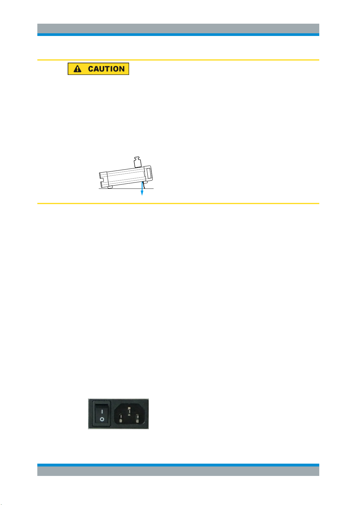
1.1.5 Connecting the R&S IQR to the AC Supply
The I/Q Data Recorder is automatically adapted to the AC supply voltage. The supply
voltage must be in the range 100 V to 240 V; 50 Hz to 60 Hz. The mains connector and
power switch are located at the rear panel.
12User Manual 1175.6326.02 ─ 12
Page 13
R&S®IQR
Preparing the I/Q Data Recorder for Use
Front Panel Tour
Connect the I/Q Data Recorder to the AC power source using the AC power cable
delivered with the unit. The maximum and typical power consumption of the I/Q Data
Recorder is listed in the data sheet.
1.1.6 Power on and off
The mains connector and power switch are located at the rear panel.
To turn the power on or off, press the AC power switch to position I (On) or 0 (Off).
After power-on, the I/Q Data Recorder is in standby or ready state, depending on the
state of the standby key at the front panel.
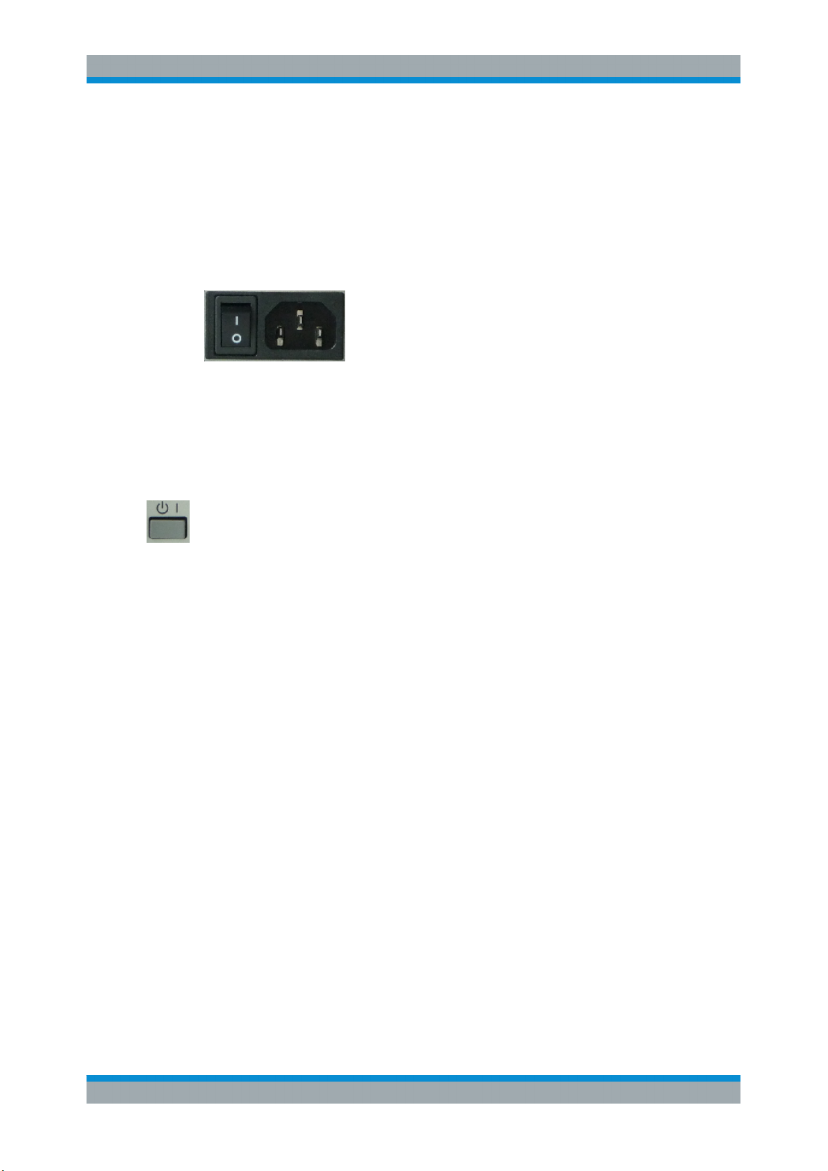
1.1.7 Standby and Ready State
The standby key connects/disconnects all internal modules of the I/Q Data Recorder
to/from the DC supply voltage generated by its internal power supply. In standby state
(orange PWR LED) the power consumption of the I/Q Data Recorder is very small,
however, the internal power supply is still connected to the AC mains power as long as
the mains power switch at the rear panel is on.
In ready state (green PWR LED) all modules are power-supplied and the I/Q Data
Recorder can be used as described in Chapter 2, "Basic R&S IQR Operation",
on page 24.
It is recommendable to switch the I/Q Data Recorder to standby state or switch it off by
the rear panel AC power switch if it is not used for some time. Observe the instructions
for startup and shutdown in Chapter 1.4, "Starting and Shutting Down the Instrument",
on page 18.
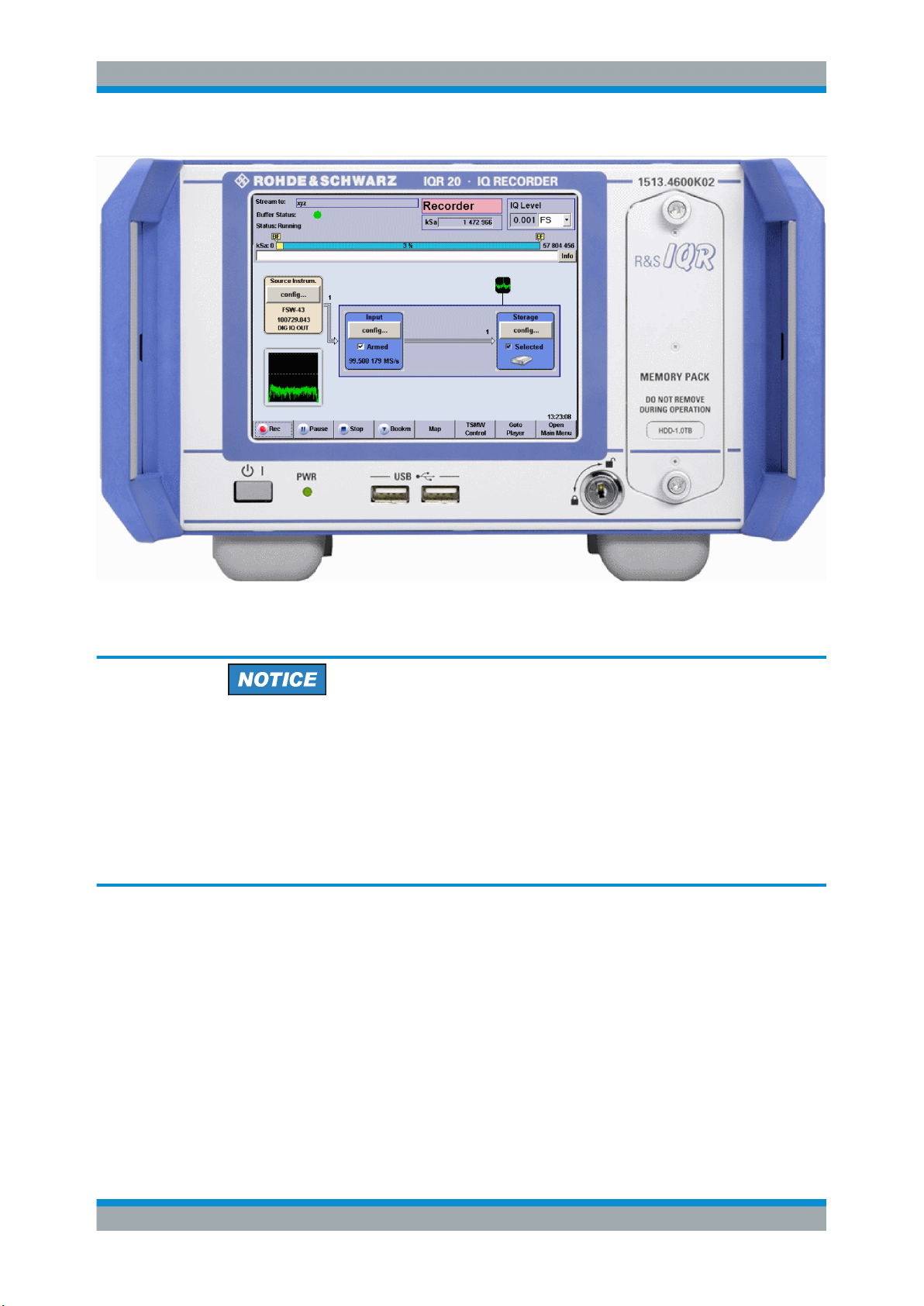
1.2 Front Panel Tour
The front panel of the I/Q Data Recorder provides the touchscreen display, the standby
key with a power status LED (PWR), two type A USB connectors, and the removable
memory pack, to be locked by a key.
13User Manual 1175.6326.02 ─ 12
Page 14
R&S®IQR
Preparing the I/Q Data Recorder for Use
Front Panel Tour
In the following sections the front panel elements are described from top left to bottom
right.
Instrument damage caused by cleaning agents
Cleaning agents contain substances that may damage the instrument. For example,
cleaning agents that contain a solvent may damage the front panel labeling, plastic
parts, or the display.
Never use cleaning agents such as solvents (thinners, acetone, etc), acids, bases, or
other substances.
The outside of the instrument can be cleaned sufficiently using a soft, lint-free dust
cloth.
1.2.1 Display
The I/Q Data Recorder is equipped with a touchscreen display. It is also possible to
control the instrument via mouse and/or keyboard. Both can be connected to the USB
connectors on the front panel.
The GUI elements are described in Chapter 5, "General and Administrative Tasks",
on page 79.
14User Manual 1175.6326.02 ─ 12
Page 15

R&S®IQR
Preparing the I/Q Data Recorder for Use
Front Panel Tour
1.2.2 Standby Key
The standby key connects/disconnects all internal modules of the I/Q Data Recorder
to/from the DC supply voltages generated by its internal power supply.
See Chapter 1.1.7, "Standby and Ready State", on page 13.
The PWR LED indicates whether the I/Q Data Recorder is ready to operate (LED
green) or in standby state (LED is orange).
The LED does not light when the AC power switch on the rear panel is in position 0
(Off).
1.2.3 USB Connectors
The USB connectors of type A (master USB) may be used to connect e.g. a keyboard,
mouse or other pointing devices or an external storage device (USB stick, CD-ROM
drive etc.).
Additional USB connectors are located on the rear panel of the I/Q Data Recorder.
The length of the connecting USB cables should not exceed 1 m. The maximum current per USB port is 500 mA. See also Chapter 1.1.4, "EMI Suppression", on page 12.
To avoid disturbances, do not connect or disconnect USB devices while data is being
recorded or replayed.
1.2.4 Memory Pack
The removable memory pack contains two hard disk drives or two solid state drives.
Additional memory packs are available as options R&S IQR-B020, "HDD Module 2 TB,
80 MByte/s", R&S IQR-B109F, "SSD Module 0.9 TB, 400 MByte/s", R&S IQR-B119F,
"SSD Module 1.9 TB, 400 MByte/s" and R&S IQR-B138F, "SSD Module 3.8 TB,
400 MByte/s".
15User Manual 1175.6326.02 ─ 12
Page 16

R&S®IQR
Preparing the I/Q Data Recorder for Use
Rear Panel Tour
The data rates and maximum recording times of the memory packs depend on the
operating mode of the source instrument; refer to the data sheet for details.
The memory pack is secured by a key. You can replace the pack while the key is in its
vertical (unlocked) position: Turn the two screws on the top and bottom counterclockwise off the threads, then pull out the memory pack in horizontal direction. Insert the
new memory pack in reverse order.
Risk of data loss
The memory pack must not be removed while the R&S IQR is in ready state, or while
data is recorded or replayed. Always switch the instrument to standby (or turn the
power off) before you remove the memory pack. See Chapter 1.2.2, "Standby Key",
on page 15.
Backups of recorded data
The hard disk and solid state drives in the memory packs have a limited useful life,
depending on the number of recording cycles and their repetition rate. For details refer
to the R&S IQR data sheet. To prevent loss of valuable data, perform regular backups
using the archiving function; see Chapter 5.5, "Tools", on page 84.
1.3 Rear Panel Tour
The rear panel contains the mains connector with the AC power switch and several
connectors for instrument control and digital I/Q data transfer.
16User Manual 1175.6326.02 ─ 12
Page 17

R&S®IQR
Preparing the I/Q Data Recorder for Use
Rear Panel Tour
From top to bottom, the different connectors serve the following purpose.
LAN 1 / LAN 2
Two 8-pin RJ-45 connectors to integrate the I/Q Data Recorder into a Local Area Network (LAN), e.g. for remote control (LAN 1) or for control of an R&S TSMW or an
Rohde & Schwarz Signal Generator using option R&S IQR-K1 or R&S IQR-K2 (LAN
2). The pin assignment of the RF-45 connectors supports category 6 / 7 UTP/STP
(Unshielded/Shielded Twisted Pair) cables. See also Chapter 1.1.4, "EMI Suppres-
sion", on page 12 and Chapter 1.6.4, "Connecting a LAN Cable", on page 22.
Mains connector and switch
The mains connector and power switch is located in the upper part of the rear panel;
see also Chapter 1.1.6, "Power on and off", on page 13.
I/O 1 to I/O 8 connectors
Configurable BNC connectors for the following input or output control signals.
●
External sampling clock input signal (fixed input I/O 1, player mode; see Chap-
ter 4.2.4.1, "Clock", on page 72)
●
External trigger input signals (I/O 1 to I/O 8, player or recorder mode; see "Control
Line Setup" on page 71)
17User Manual 1175.6326.02 ─ 12
Page 18

R&S®IQR
Preparing the I/Q Data Recorder for Use
Starting and Shutting Down the Instrument
DVI
External monitor connector; see Chapter 1.6.3, "Connecting a Monitor", on page 21.
Master USB Connectors
Four type A USB connectors (master USB), equivalent to the master USB connectors
on the front panel; see Chapter 1.2.3, "USB Connectors", on page 15.
DIGITAL IQ IN / DIGITAL IQ OUT 1/2
Input and output connectors for digital signals. Use DIGITAL IQ IN for data recording,
DIGITAL IQ OUT 1/2 for replay. An appropriate cable is supplied with the R&S IQR.
Note: It is not possible to use the two I/Q connectors simultaneously except for running
the "DIG I/Q Interface" selftest.
REF IN / REF OUT
Two BNC connectors for external/internal 10 MHz reference frequency signals; see
Chapter 4.2.4.1, "Clock", on page 72.
●
Use REF IN to synchronize the R&S IQR to another device.
●
Use REF OUT to synchronize another device to the R&S IQR.
Additional Connectors
The type B USB connector (slave USB) labeled USB DEVICE and the DISPLAY PORT
connector are intended for future extensions.
1.4 Starting and Shutting Down the Instrument
To start the R&S IQR, proceed as follows:
1. Make sure that the I/Q Data Recorder is connected to the AC power supply and the
power switch on the rear panel is in position I (On).
2. If necessary, press the standby toggle switch on the front panel to switch the
instrument to ready state (the PWR LED is green).
See also Chapter 1.1.7, "Standby and Ready State", on page 13
In ready state, the R&S IQR automatically performs a system check, boots the Windows® XP Embedded operating system ("Booting Windows®, please wait...") and then
starts the R&S IQR application, showing its startup screen.
18User Manual 1175.6326.02 ─ 12
Page 19

R&S®IQR
Preparing the I/Q Data Recorder for Use
Starting and Shutting Down the Instrument
Figure 1-1: R&S IQR startup screen
If the previous session was terminated regularly, the R&S IQR application uses the last
instrument configuration.
Once the startup procedure has been terminated, the "Player" main dialog is displayed.
See Chapter 2.4, "Replaying Data", on page 36.
To shut down the R&S IQR, proceed as follows:
1. Press the standby toggle switch to save the current instrument configuration, close
the R&S IQR application, shut down the Windows® XP Embedded operating system and set the instrument to standby state. You can also perform this procedure
step by step like in any Windows® session.
2. If desired, set the AC power switch to position 0 (Off).
Standby state
It is strongly recommended to switch the R&S IQR to standby state before disconnecting it from the AC supply. If you set the power switch to 0 while the R&S IQR application is still running, you will lose the current settings. Moreover, loss of program data
cannot be excluded if the application is terminated improperly.
19User Manual 1175.6326.02 ─ 12
Page 20

R&S®IQR
Preparing the I/Q Data Recorder for Use
Connecting External Accessories
1.5 Instrument Control
The R&S IQR can be controlled in the following ways:
●
Using the touchscreen display. The functions of the Graphical User Interface (GUI)
are described in Chapter 5, "General and Administrative Tasks", on page 79.
●
With a remote desktop connection through a Local Area Network, see Chap-
ter 10.2, "Remote Operation in a LAN", on page 177
●
With an external monitor in combination with a mouse and/or keyboard, see Chap-
ter 1.6.3, "Connecting a Monitor", on page 21.
1.6 Connecting External Accessories
The equivalent USB ports on the front and rear panel of the R&S IQR can be used to
connect a variety of accessories:
●
A mouse simplifies operation of the instrument using the controls and dialogs of the
Graphical User Interface (GUI).
●
A keyboard simplifies the entry of data.
In addition the R&S IQR provides interfaces for monitor connection and network integration:
●
An external monitor shows the magnified Graphical User Interface (GUI) with all
diagram areas and controls.
●
A LAN connection can be established in order to access the hard disk or control
the tester from an external PC.
1.6.1 Connecting a Mouse
A USB mouse can be connected to one of the Universal Serial Bus (USB) connectors
on the front panel or on the rear panel.
The mouse is detected automatically when it is connected. It is safe to connect or disconnect the mouse while the R&S IQR is in ready state.
Risk of data loss
Do not connect or disconnect the mouse while data is being recorded or replayed.
20User Manual 1175.6326.02 ─ 12
Page 21

R&S®IQR
Preparing the I/Q Data Recorder for Use
Connecting External Accessories
Mouse configuration
Use the "Start - Control Panel - Mouse" menu of Windows® XP Embedded to configure
the mouse properties. To access Windows® XP Embedded, use the on-screen keyboard or connect an external keyboard to your R&S IQR and press the Windows key +
D.
Operating an R&S IQR does not require a mouse. You can access all essential functions using the keys on the front panel.
1.6.2 Connecting a Keyboard
A keyboard can be connected to one of the Universal Serial Bus (USB) connectors on
the front panel or on the rear panel.
The keyboard is detected automatically when it is connected. The default input language is English - US. It is safe to connect or disconnect the external keyboard while
the R&S IQR is in ready state.
Risk of data loss
Do not connect or disconnect the keyboard while data is being recorded or replayed.
Keyboard configuration
Use the "Start - Control Panel - Keyboard" or "Regional and Language Options" menu
of Windows® XP Embedded to configure the keyboard properties. To access Windows® XP Embedded, use the on-screen keyboard or connect an external keyboard to
your R&S IQR and press the Windows key + D.
Operating the R&S IQR does not require a keyboard. You can access all functions
using the touchscreen display.
1.6.3 Connecting a Monitor
A standard monitor can be connected to the DVI-D connector of the R&S IQR.
Monitor connection
The monitor must be connected while the instrument is switched off (in standby mode).
Otherwise correct operation cannot be guaranteed.
The monitor displays the magnified Graphical User Interface (GUI) with all dialogs and
control elements. No extra configuration is required.
21User Manual 1175.6326.02 ─ 12
Page 22

R&S®IQR
Preparing the I/Q Data Recorder for Use
Connecting External Accessories
Instrument control from the monitor
With an additional mouse or keyboard connected to the tester, you can control the
measurement from the external monitor.
You may also connect a VGA monitor using an appropriate adapter.
1.6.4 Connecting a LAN Cable
A LAN cable can be connected to any of the LAN connectorsof the R&S IQR. Refer to
Chapter 10.2, "Remote Operation in a LAN", on page 177 and learn how to avoid con-
nection errors before you establish a LAN connection.
Connect a CAT6 or CAT7 RJ-45 (LAN, Ethernet) cable to one of the LAN ports LAN 1
or LAN 2 on the rear panel of the R&S IQR. See also Chapter 1.1.4, "EMI Suppres-
sion", on page 12.
Direct Ethernet connection
The LAN ports of the R&S IQR are auto-crossover Ethernet ports. You can connect
them to a network that is equipped with Ethernet hardware (hub, switch, router), but
you can also set up a direct connection to a computer or another test instrument. For
both connection types, you can use either crossover or standard straight-through
Ethernet cables.
The LAN connectors LAN 1 and LAN 2 are configured independently. See also Chap-
ter 10.2.1, "Assigning IP Addresses", on page 178.
1.6.5 Test Setups with Two LAN Connections
Two LAN connectors LAN 1 and LAN 2 are located on the rear panel of the R&S IQR.
With one LAN connector used to establish a connection to a home/company network,
the other one can be used to connect an additional instrument, e.g. an R&S TSMW
"Universal Radio Network Analyzer".
With two LAN connections, it is possible to use the R&S IQR in two alternative ways:
●
As a client participating in two independent networks, one comprising the company
network including the tester, the second consisting of the additional test instrument
plus the tester. The default IP address settings of the R&S IQR are optimized for
this kind of network topology; LAN 1 is the preferred connector for the company
LAN.
●
As a data router between the additional test instrument and the company network.
This configuration means that the tester and the additional test instrument are integrated into a single network.
22User Manual 1175.6326.02 ─ 12
Page 23

R&S®IQR
Preparing the I/Q Data Recorder for Use
Connecting External Accessories
The network topology is defined in Windows® XP's "Control Panel - Network Connections - Local Area Connection Status - Local Area Connection Properties - Internet Protocol (TCP/IP) Properties - Advanced TCP/IP Settings" dialog. Both LAN interfaces
must have independent IP addresses; see Chapter 10.2.1, "Assigning IP Addresses",
on page 178. Contact your LAN administrator for details.
Avoid parallel connections
Never use both LAN connectors to connect the R&S IQR in parallel to the same network as this will result in connection errors.
23User Manual 1175.6326.02 ─ 12
Page 24

R&S®IQR
Basic R&S IQR Operation
Recording Data
2 Basic R&S IQR Operation
This chapter describes the use of an R&S IQR I/Q Data Recorder for data recording
and replay. For a detailed description of the complete functionality of the instrument
refer to the subsequent chapters.
Instrument setup and safety instructions
Please notice the instructions in chapter "Preparing the I/Q Data Recorder for Use"
before working with your I/Q Data Recorder.
To avoid disturbances, do not run other applications, connect or disconnect USB devices, or configure the Windows® operating system while data is being recorded or
replayed.
2.1 Required Equipment
The measurement examples in this chapter require a R&S IQR20 or R&S IQR100 I/Q
Data Recorder. Control of both instruments is analogous.
In principle, any Rohde & Schwarz instrument which is equipped with an R&S Digital
I/Q Interface can serve as a source instrument for recording and/or a destination instrument for data replay. In the examples below, an R&S AMU200A Digital Baseband
Generator and Fading Simulator is used. The R&S AMU200A serves as a I/Q data
source for recording. In a replay session, data can be transferred to the R&S
AMU200A; a typical task is fading of the replayed baseband data.
Touchscreen operation
The functionality of the R&S IQR is accessible by tapping on the touchscreen elements. No mouse or external keyboard is required to perform any of the tasks described in this chapter.
2.2 Recording Data
Data recording requires a connection to a suitable I/Q data "Source Instrument":
Recording will start only if the source instrument transmits data to the DIGITAL IQ IN
connector at the rear panel of the R&S IQR.
To establish the test setup and prepare the instruments,
1. Connect the R&S IQR to the source instrument (here: the R&S AMU200A) as
shown below. Use the I/Q data cable which you received with your R&S IQR to
establish the digital I/Q data connection. No additional cabling is needed; the R&S
24User Manual 1175.6326.02 ─ 12
Page 25

R&S®IQR
Basic R&S IQR Operation
Recording Data
Digital I/Q Interface ensures all the necessary communication between the two
instruments.
Figure 2-1: Basic test setup for data recording
2. Switch on both instruments and make sure the R&S AMU200A is configured to
transmit data at BASEBAND DIGITAL OUT. Refer to the R&S AMU200A operating
manual for details.
See also Chapter 1.4, "Starting and Shutting Down the Instrument", on page 18.
Checking the connection
After the R&S IQR has completed its startup procedure, the "Source Instrum." control
block of the "Recorder" window shows the connected instrument with its serial number
and digital output connector.
2.2.1 Basic Operating Sequence
In the following example, the I/Q data stream from the R&S AMU200A is stored to a
data file 2june16. The maximum file size is restricted to 100 megasamples; manual
trigger mode is used.
25User Manual 1175.6326.02 ─ 12
Page 26

R&S®IQR
Basic R&S IQR Operation
Recording Data
After startup, the R&S IQR shows its main window in "Recorder" mode.
1.
2. Tap "Open Main Menu" and "Configuration File > Set to default..." to preset your
R&S IQR. This ensures that the behavior of the instrument is as described in this
section.
26User Manual 1175.6326.02 ─ 12
Page 27

R&S®IQR
Basic R&S IQR Operation
Recording Data
3. Tap "Goto Recorder" to return to the GUI for I/Q data recording.
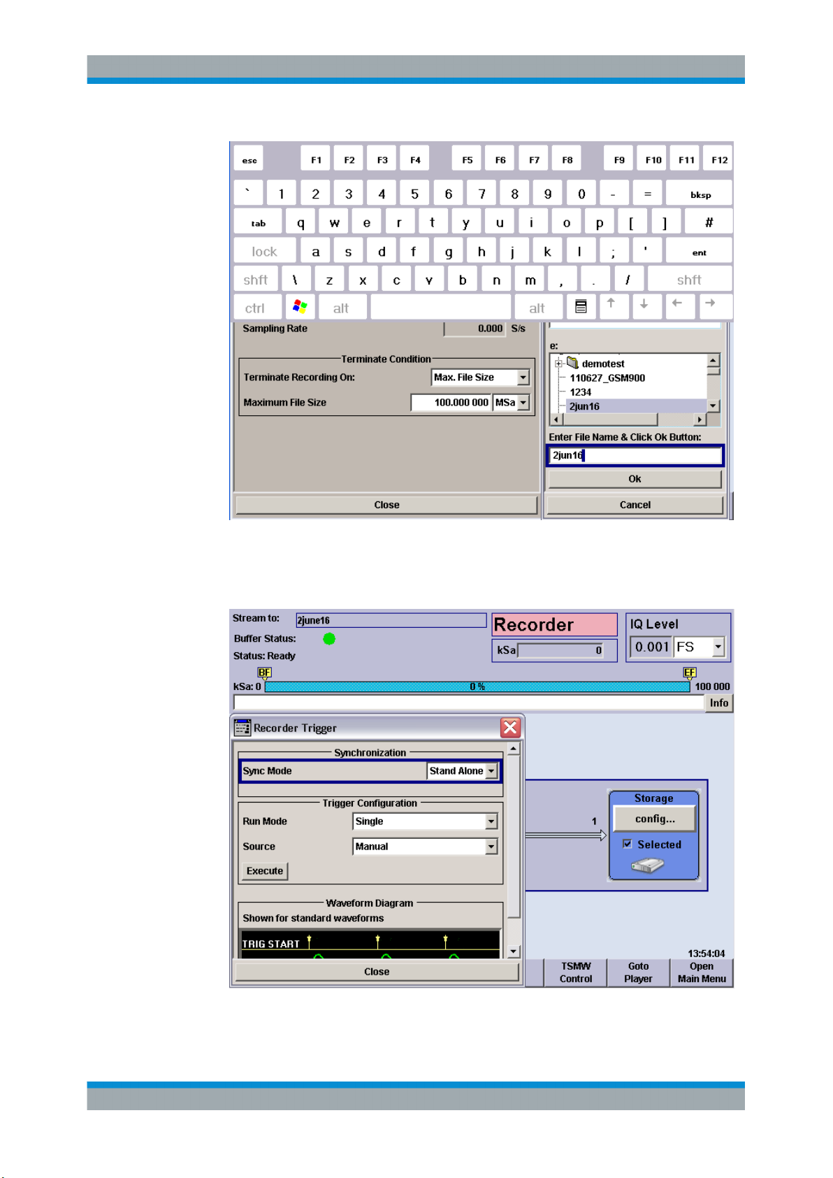
4. Tap "Storage > config..." and use the on-screen keyboard to define a "Maximum
File Size" of 100 MSa (megasamples). See also Chapter 10.1, "On-Screen Key-
board", on page 177.
The R&S IQR will stop recording when the recorded file has reached the size of
approx. 100 MSa. For more information refer to "Terminate Condition"
on page 55.
5. Tap "Save Stream Data..." and use the on-screen keyboard to enter the file name,
e.g. 2june16, in the "Save Stream Data" dialog. Tap the "Ok" button below the
entry field.
The I/Q data file 2june16.ws1 will be written to partition e:\ of the removable
memory pack; a second file 2june16.ws2 will be stored in partition f:\. See also
Chapter 4.1, "General Description", on page 59.
27User Manual 1175.6326.02 ─ 12
Page 28
R&S®IQR
Basic R&S IQR Operation
Recording Data
6. Close the mass storage dialogs and the on-screen keyboard.
7. Tap "Input > config..." to open the "Trigger" dialog. Ensure that "Manual" trigger
source is selected.
28User Manual 1175.6326.02 ─ 12
Page 29

R&S®IQR
Basic R&S IQR Operation
Recording Data
8. Tap "Execute" to configure the R&S IQR and the memory according to your settings.
Configuration is finished when the box with the progress bar is closed and the status message "Please wait..." has disappeared.
9. Close the "Recorder Trigger" dialog.
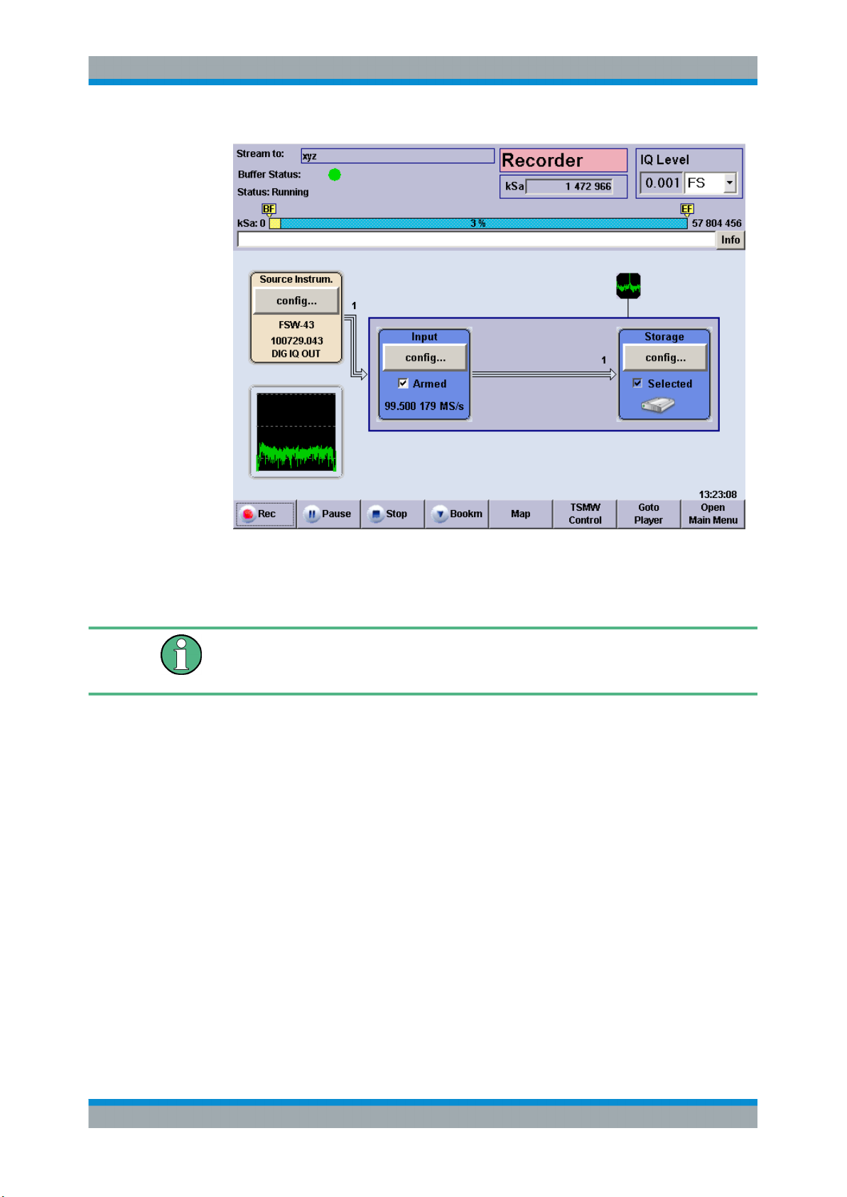
Both the "Input" and "Storage" configuration blocks must be blue. The used sample
rate is shown in the "Input" box.
10. Tap the "Rec" control button in the lower left corner of the dialog to start recording.
Tap "Stop" or "Pause" if you wish to stop or interrupt recording.
The progress bar and the "kSa:" output field in the upper part of the main window
show the progress of data recording. Recording is terminated, and a message is
displayed, when the maximum file size has been reached.
29User Manual 1175.6326.02 ─ 12
Page 30
R&S®IQR
Basic R&S IQR Operation
Recording Data Using TSMW Control
11. If you wish to repeat data recording using the same data file, you can simply tap
"Rec" again.
A message box prompts you to confirm that the stored data can be overwritten.
Recorded data is stored in blocks with a 10 MByte block size. When recording is stopped, the currently recorded data block is discarded; only complete 10 MByte blocks are
stored. See also "Terminate Condition" on page 55.
2.2.2 Possible Extensions
You can modify the trigger settings to refine the amount of recorded data; see Chap-
ter 3.1.1, "Trigger System", on page 40. Moreover, you can include bookmarks in the
recorded file. For an example refer to Chapter 2.3, "Recording Data Using TSMW Con-
trol", on page 30.
2.3 Recording Data Using TSMW Control
An R&S TSMW "Universal Radio Network Analyzer" with a digital I/Q interface can be
used for data recording as outlined in the previous example (see Chapter 2.2, "Record-
ing Data", on page 24). If the R&S IQR is equipped with option R&S IQR-K1, "TSMW
Control", you can configure the R&S TSMW from the R&S IQR, control measurements,
and record the measured I/Q data. No additional control device is required.
30User Manual 1175.6326.02 ─ 12
Page 31

R&S®IQR
Basic R&S IQR Operation
Recording Data Using TSMW Control
To establish the test setup and prepare the instruments,
1. Connect the R&S IQR to the R&S TSMW as shown below. Use the I/Q data cable
which you received with your R&S IQR to establish the digital I/Q data connection.
Use a LAN cable to enable control of the R&S TSMW by R&S IQR-K1. If you wish
to record additional GPS meta data using the built-in GPS receiver of the R&S
TSMW, connect a USB cable between the "GPS" USB type B connector of the
R&S TSMW and any of the master USB connectors of the R&S IQR.
Figure 2-2: Basic test setup for TSMW control
2. Switch on both instruments.
LAN connection
In the factory configuration, the LAN 2 interface of the R&S IQR and the R&S TSMW
have fixed IP addresses; the IP address of R&S IQR-K1 matches the R&S TSMW
address. It is recommended to use LAN 2 for the connection to the R&S TSMW and to
leave all IP address settings unchanged. For more information refer to Chapter 10.2,
"Remote Operation in a LAN", on page 177.
2.3.1 Basic Operating Sequence
The following example simulates a test drive with an R&S TSMW. R&S IQR-K1 is used
to record a WCDMA downlink signal at 2120 MHz. During the test drive, bookmarks
are used to label the beginning and the end of a tunnel.
If option R&S IQR-K1 is unlocked and enabled, the "Recorder" window of the R&S IQR
contains a "TSMW Control" button.
31User Manual 1175.6326.02 ─ 12
Page 32

R&S®IQR
Basic R&S IQR Operation
Recording Data Using TSMW Control
1. Preset your R&S IQR as described in Chapter 2.2.1, "Basic Operating Sequence",
on page 25. This ensures that the behavior of the instrument is as described in this
and in the following sections.
2. Proceed as described in Chapter 2.2.1, "Basic Operating Sequence", on page 25
to define the maximum file size of the recorded data file (e.g. 10 GSa) and select a
file name (e.g. 2june16).
3. Tap "TSMW Control" to load the control interface.
After a startup screen, the R&S IQR displays the "Workspace" tab of the control
interface.
32User Manual 1175.6326.02 ─ 12
Page 33

R&S®IQR
Basic R&S IQR Operation
Recording Data Using TSMW Control
4. Tap "Filter Design" to open the associated tab. Select an appropriate bandwidth
and tap "*1.25" to obtain the recommended sample rate. Tap "Generate" to terminate your settings.
33User Manual 1175.6326.02 ─ 12
Page 34

R&S®IQR
Basic R&S IQR Operation
Recording Data Using TSMW Control
5. Tap "Save As" and store your filter configuration to a file, e.g. "WCDMA.flt".
6. Open the "Front Ends" tab, select the created filter file and enter a "Center Frequency" of 2120 MHz.
7.
Tap the start button in the control bar at the bottom of the R&S IQR-K1 interface
to start recording. For two frontends two arrows are blinking.
As recording starts, the control interface indicates that the LAN and Digital I/Q connections are established
8. Tap the "IQR" button to return to the "Recorder" window.
9. At the beginning of the tunnel, press "Bookm". Enter an appropriate "Comment" as
shown below.
.
34User Manual 1175.6326.02 ─ 12
Page 35

R&S®IQR
Basic R&S IQR Operation
Recording Data Using TSMW Control
10. Click "Ok" to close the dialog. At the end of the tunnel, set a second bookmark.
The toolbar shows the percentage of recorded data, relative to the selected maximum file size, and the positions of the bookmarks.
11. Use the control buttons "Recorder" window if you wish to pause or stop recording.
Recorded data is stored in blocks with a 10 MByte block size. When recording is stopped, the currently recorded data block is discarded; only complete 10 MByte blocks are
stored. See also "Terminate Condition" on page 55.
35User Manual 1175.6326.02 ─ 12
Page 36

R&S®IQR
Basic R&S IQR Operation
Replaying Data
2.4 Replaying Data
In a replay session, the recorded I/Q data is transferred to a destination instrument with
an R&S Digital I/Q Interface where it can be analyzed or further processed. For the following example we assume that a I/Q data file 2june16 has been stored on the
removable memory pack of the R&S IQR following the procedure in Chapter 2.2,
"Recording Data", on page 24.
To adjust the previous test setup for data replay,
1. Change the I/Q data connection as shown below: Connect the DIGITAL IQ OUT
connector of the R&S IQR to the BASEBAND DIGITAL IN connector of the R&S
AMU200A. For accurate sampling rates of the replayed data, use one of the four
delivered BNC cables for a reference frequency connection. No additional cabling
is needed; the R&S Digital I/Q Interface ensures all the necessary communication
between the two instruments.
Figure 2-3: Basic test setup for data replay
2. Ensure that both instruments are switched on and that the R&S AMU200A is configured to use an external reference frequency and receive data at BASEBAND
DIGITAL IN. Refer to the R&S AMU200A operating manual for details.
Checking the connection
After the R&S IQR has completed its startup procedure, the "Dest. Instrum." control
block of the "Player" window shows the connected instrument with its serial number
and digital output connector.
2.4.1 Basic Operating Sequence
In the following example, the data file 2june16 recorded in section Recording Data is
replayed using manual trigger mode.
1. If the R&S IQR is still in "Recorder" mode, tap "Goto Player".
36User Manual 1175.6326.02 ─ 12
Page 37

R&S®IQR
Basic R&S IQR Operation
Replaying Data
2. Tap "Mass Storage > config...".
3. In the dialog opened, select the data file 2june16 on drive e:\. See also Chap-
ter 4.1, "General Description", on page 59.
4. Tap "OK" to close the "Load Waveform" dialog.
37User Manual 1175.6326.02 ─ 12
Page 38

R&S®IQR
Basic R&S IQR Operation
Replaying Data
Configuration is finished when the box with the progress bar is closed and the status message "Please wait..." has disappeared.
5. Tap the "Play" control button in the lower left corner of the dialog to start the replay.
Tap "Stop" or "Pause" if you wish to stop or interrupt replay.
The progress bar and the "kSa:" output field in the upper part of the main window
show the replay progress. Data replay is terminated, and a message is displayed,
when the entire file has been replayed.
6. If you wish to repeat data replay using the same data file, you can simply tap "Play"
again.
Data replayed in "Streaming" mode is transferred in blocks with a 10 MByte block size.
When replay is stopped, the currently replayed data block is discarded; only complete
10 MByte blocks are transferred.
2.4.2 Possible Extensions
If you want to replay part of the stored samples only, you can tap "GoTo" and define
the start and stop sample numbers. If the replayed file contains bookmarks, you can
use these bookmarks to define the start and stop samples.
You can modify the trigger settings to refine the amount of recorded data; you can also
replay waveform (ARB) files and modify the replayed data. For an overview of replay
features refer to Chapter 3.1.1, "Trigger System", on page 40.
38User Manual 1175.6326.02 ─ 12
Page 39

R&S®IQR
Basic R&S IQR Operation
Replaying Data Using Generator Control
You can also feed the replayed I/Q data stream to an appropriate signal generator (e.g.
an R&S SMU200A) in order to re-generate and analyze the modulated RF signal under
laboratory conditions.
2.5 Replaying Data Using Generator Control
An Rohde & Schwarz signal generator (like R&S SMBV100A, R&S SMU, R&S SFC,
R&S SFE) with a digital I/Q interface can be used for data replay. If the R&S IQR is
equipped with option R&S IQR-K2, "Generator Control", you can configure the Rohde
& Schwarz signal generator from the R&S IQR, preset the device, control measurement parameters, and replay the measured I/Q data. No additional control device is
required.
To establish the test setup and prepare the instruments
1. Connect the R&S IQR to the signal generator as shown below. Use the I/Q data
cable which you received with your R&S IQR to establish the digital I/Q data connection. Use a LAN cable to enable control of the signal generator by R&S IQR-K2.
For accurate sampling rates of the replayed data, use one of the four delivered
BNC cables for a reference frequency connection.
Figure 2-4: Test setup for data replay using Generator Control
2. Switch on both instruments.
If option R&S IQR-K2 is unlocked and enabled, the "Player" window of the
R&S IQR contains a "Generator Control" button. Tap the "Generator Control" to
load the control interface.
For further details on R&S IQR-K2, see Chapter 6.2, "R&S Generator Control
(R&S IQR-K2)", on page 96 .
39User Manual 1175.6326.02 ─ 12
Page 40

R&S®IQR
Data Recording
General Description
3 Data Recording
This chapter describes the use of the R&S IQR in "Recorder" mode, where it can
record an I/Q data stream and store it in a file on its internal disk.
● General Description................................................................................................ 40
● GUI Reference........................................................................................................ 43
3.1 General Description
In "Recorder" mode, the R&S IQR records the digital data stream that it receives via
the DIGITAL IQ IN connector. The essential stages of data recording are shown below,
together with the corresponding configuration blocks and controls of the R&S IQR. The
light brown configuration blocks can be activated in arbitrary order. Perform the necessary settings, then arm the trigger system before you start recording.
Figure 3-1: Basic data recording stages
The data is usually provided by a source instrument with a compatible R&S Digital I/Q
Interface, e.g a signal generator or a network scanner. A typical test setup with an R&S
AMU200A Baseband Signal Generator and Fading Simulator is shown in Chapter 2.2,
"Recording Data", on page 24.
Related information
●
Measurement example, including necessary preparations; see Chapter 2.2,
"Recording Data", on page 24
●
GUI reference, see Chapter 3.2, "GUI Reference", on page 43
●
Programming example, see Chapter 8.2, "Recording Data", on page 109
●
Remote control command reference, see Chapter 9.3, "Recorder Commands",
on page 122
The following sections give a general description of the essential concepts and data
transfer settings.
3.1.1 Trigger System
The trigger system starts and stops data recording. With a suitable combination of trigger settings, an exact control of the amount of recorded data and their timing is possi-
40User Manual 1175.6326.02 ─ 12
Page 41

R&S®IQR
Data Recording
General Description
ble. The recorder trigger system is very similar to the trigger system for "Player" mode,
however, the settings do not overwrite each other. Refer to Chapter 4.1.1, "Trigger
System", on page 60 for a detailed description of the trigger modes, observing the
information in the remainder of this section.
Note the following differences compared to "Player" mode.
●
In "Recorder" mode, the trigger system controls data recording.
●
The amount of recorded data is defined by the "Terminate Condition" in the "Mass
Storage" dialog. Recording stops when a maximum file size or recording duration
has been reached, or when the disk is full.
●
Recording stops when the "Terminate Condition" is satisfied. No continuous
recording is supported.
●
Data recording may be triggered by the recorded data stream itself; see Chap-
ter 3.1.1.2, "Additional Trigger Sources for Recording", on page 42.
●
Different synchronized operation; see Chapter 3.1.1.1, "Standalone and Synchron-
ized Operation", on page 41
Trigger system and recorder control buttons
Data recording is controlled using the "Rec", "Pause", and "Stop" buttons across the
bottom of the GUI. The trigger settings are effective after you check the "Input >
Armed" box and tap "Rec". "Pause" and "Stop" discontinue recording, irrespective of
the trigger settings.
While data recording is "Running", all control elements of the GUI except "Pause",
"Stop" and spectrum display handling are disabled.
3.1.1.1 Standalone and Synchronized Operation
The R&S IQR may operate as an independent unit or in combination with a second
instrument.
The following "Synchronization Modes" are available:
●
Stand Alone: The R&S IQR operates as an independent unit, recording a single
data stream. The full range of "Recorder Trigger" settings is available. If an external trigger source is selected, the trigger signal must be applied to the I/O connectors selected via "Control Line Setup > Trigger Start / Gate On" and "Trigger Stop".
●
Master: The R&S IQR acts as a master for a second R&S IQR; both instruments
can record two I/Q data streams, starting at the same time. The recording times of
the master and slave R&S IQR may differ from one another, depending on the
sampling rates of the source instruments and the "Terminate Condition" settings.
The "Recorder Trigger" settings can be used without restriction, however, I/O 7 is
reserved for the external trigger signal destined for the slave instrument.
Establish a trigger connection to the slave instrument as shown in the drawing. The
sample clock connection is not needed; the sampling rates for master and slave
are determined by the source instruments.
41User Manual 1175.6326.02 ─ 12
Page 42

R&S®IQR
Data Recording
General Description
Possible master configuration: External trigger from a third instrument. "Trigger
Start / Gate On: I/O 2", "Trigger Stop: Off".
Slave configuration: "Sync Mode: Slave". This means that the slave instrument
uses the "Trigger Start / Gate On" signal fed in at I/O 7. No "Trigger Stop" signal is
used.
●
Slave: Data recording of the R&S IQR is controlled by a second, master R&S IQR.
The master instrument can use arbitrary trigger and clock source settings; see
above. The slave instruments enables recording typically 100ns after the master
instrument. Note that on low sample rates it can take considerable time until the
first sample is received after recording has been enabled. The slave R&S IQR is
set to external trigger mode; the trigger signal is fed in via I/O 7.
Establish a trigger connection to the master instrument as shown in the drawing.
The sample clock connection is not needed; the sampling rates for master and
slave are determined by the source instruments.
3.1.1.2 Additional Trigger Sources for Recording
In "Recorder" mode, the R&S IQR supports all trigger sources described in Chap-
ter 4.1.1, "Trigger System", on page 60. In addition, recording may be triggered by
the information in the received I/Q data stream.
●
I/Q Level: The R&S IQR evaluates the level of each data sample and starts record-
ing as soon as a specific threshold value ("Level") is exceeded.
42User Manual 1175.6326.02 ─ 12
Page 43

R&S®IQR
Data Recording
GUI Reference
●
DIG IQ GP: One of the digital general purpose signals GP1 to GP4 provides the
trigger events. The GP signals must be included in the recorded data stream; they
are fed in via the DIGITAL IQ IN connector; along with the I and Q samples.
Most of the trigger settings described in Chapter 3.2.3.1, "Trigger Settings",
on page 49 are valid for the "DIG IQ GP" trigger source. The GP trigger signals
can be used in two different ways: In "Edge Trigger" mode each rising or falling
edge of the selected GP signal provides a single trigger event. In "Gated Trigger"
mode, recording is restricted to the high periods of the GP signals.
3.1.2 Streaming Files
When recording data, the R&S IQR creates a pair of I/Q data files of equal size. The
files have the extensions *.ws1 and *ws2; they are stored to drives e:\ and f:\ of
the removable memory. It is sufficient to specify the *.ws1 file on drive e:\; the
R&S IQR will automatically create the associated *.ws2 file. See also Chapter 4.1.2,
"Streaming Mode", on page 64.
The R&S IQR inserts a tagged waveform header at the beginning of each I/Q data file.
3.1.3 General Purpose Signals
General purpose (GP) signals are digital control signals which are included in the
recorded I/Q data stream: Each I/Q sample transmitted over the R&S Digital I/Q Interface is extended by 6 GP bits. The R&S IQR can use the general purpose signals GP1
to GP4 as trigger signals (trigger source "DIG IQ GP"; see Chapter 3.1.1.2, "Additional
Trigger Sources for Recording", on page 42).
In a typical application scenario, a source instrument generates a GP signal to label
different points in time or time intervals within the transmitted I/Q data stream. The
R&S IQR uses the "DIG IQ GP" trigger in order to restrict recording to the time intervals of interest.
For the time being there are no source instruments generating GP signals.
3.2 GUI Reference
The following sections provide reference information about the elements of the Graphical User Interface (GUI) which control the R&S IQR in "Recorder" mode. For an introduction and general features refer to Chapter 3, "Data Recording", on page 40.
43User Manual 1175.6326.02 ─ 12
Page 44

R&S®IQR
Data Recording
GUI Reference
3.2.1 Main Application Window (Recorder)
The main window is divided into three parts:
●
The upper part shows the current configuration of the R&S IQR in "Recorder" mode
and information concerning the instrument status and the current recording session.
●
The center part shows the four main configuration blocks for data recording
("Source Instrum.", "Input", "Formatting", "Storage"). Additionally a Spectrum Display is provided, see Chapter 3.2.6, "Spectrum Display", on page 55. These
blocks are described in the following sections.
The "Input" control block turns blue as soon as the trigger system is "Armed"
(ready to receive trigger events in order to start recording).
Note that in "Armed" state the R&S IQR ignores messages from the source instrument (other sample rate, reference level, added channels). Also the DIG IQ cable
must not be removed or plugged in while the R&S IQR is armed, else the source
instrument will not be detected reliably.
The "Storage" block turns blue as soon as a file for the recorded data has been
selected. Recording can be started as soon as both configuration blocks are blue;
see Chapter 2.2, "Recording Data", on page 24.
Input connectors for external trigger signals are also shown in the central part (see
green symbols in the figure below). The connectors are assigned in the "Input" configuration block.
The current time is displayed in the lower right corner; this information is relevant
e.g. for the time trigger (see Chapter 4.1.1.5, "Time Trigger", on page 63).
●
The lower part provides buttons to control recording and access the main windows
for replay, optional extensions, and administrative tasks.
44User Manual 1175.6326.02 ─ 12
Page 45

R&S®IQR
Data Recording
GUI Reference
Figure 3-2: Main application window in recorder mode
Instrument status
The upper part of the main application window provides the following information.
"Stream to"
Name of the selected storage file. See Chapter 3.2.5, "Storage Set-
tings", on page 54.
"Buffer Status"
A green dot indicates normal operation (no error). A red dot indicates
that recording was stopped, most likely because the input buffer was
empty (no data available, error).
"(Trigger)ᅟ
Status"
Trigger status message. All messages are self-explanatory. "Running" indicates that data is being recorded. "Ready" means that the
trigger system has paused or stopped recording.
45User Manual 1175.6326.02 ─ 12
Page 46

R&S®IQR
Data Recording
GUI Reference
"kSa"
"Info"
Remote command:
STATus:RECorder?
TRIGger:RECorder:STATe?
MEASure:IQ:SAMPles?
Sample counter and progress bar. The default bookmark labels "BF"
and "EF" (beginning and end of file) appear in yellow boxes at the
beginning and the end of the progress bar. Additional, user-defined
bookmarks are displayed with their index numbers; see Chap-
ter 3.2.7, "Bookmarks", on page 57. Click on a bookmark label to
retrieve detailed information and to switch between all bookmarks in
the file.
The unit of the progress bar is configurable; see "GUI Configura-
tion..." on page 80.
Opens a dialog with a record of error messages. "Static" error messages are still pending (i.e. they refer to the current state of the
R&S IQR). The error "History" also contains messages from the past.
"Volatile" messages are not stored when the R&S IQR is shut down,
so they are no longer visible in later sessions. Non-volatile messages
persist. You can delete some or all of the messages from the history
list.
The "History" dialog is also used for remote control error messages;
see Chapter 7.1.1, "Activating Remote Control Mode", on page 106.
I/Q Level
Level of the recorded I/Q samples. The R&S IQR subdivides the recorded data into
groups of 32 consecutive samples. The average level is calculated for each group. The
reported "I/Q Level" is the peak value of these average levels within a time interval of
1/2 s. The result is updated every 1/2 s.
"I/Q Level" can be retrieved as a ratio relative to full scale (FS) level ("FS"), as a percentage ("% FS"), or as a logarithmic value ("dBFS"). The three units are related as
follows:
x %FS = (0.01*x) FS; x dBFS = 20 * log(x FS)
The R&S IQR uses the scaling convention where is RMS value of a full-scale sine
wave is designated 100 %FS (0 dBFS). Consequently, the I/Q levels can range up to
141.4 % FS (+3.010 dBFS).
Remote command:
MEASure:IQ:AMPLitude?
46User Manual 1175.6326.02 ─ 12
Page 47

R&S®IQR
Data Recording
GUI Reference
Control buttons
The control bar across the bottom of the screen is filled with buttons:
●
"Rec" / "Pause" / "Stop" control data recording, together with the trigger settings.
See Chapter 3.1.1, "Trigger System", on page 40.
To record data, a file must be loaded, and the trigger must be armed. Check the
trigger status information in the upper part of the dialog in case the "Rec" button
does not work. The control elements of the GUI (except "Pause" and "Stop") are
disabled while recording is in progress.
●
"Bookm" allows you to add bookmarks to the recorded file which you can later use
for replay control; see Chapter 3.2.7, "Bookmarks", on page 57.
●
"Map" is available if option R&S IQR-K102, "GPS Data Recording", and option
R&S IQR-K103, "GPS Map", is installed. The button opens a map view of the measurement track; see Chapter 6.5, "GPS Map (R&S IQR-K103)", on page 100.
●
The remaining buttons switch to other main windows and are self-explanatory. In
general, switchover is disabled while the trigger system is armed.
Tip: You can add buttons to the bar in order to start executable programs (such as
"TSMW Control" shown in the figure above); see Chapter 3.2.2, "Source Instruments",
on page 47.
Remote command:
TRIGger:RECorder:STARt
TRIGger:RECorder:PAUSe
TRIGger:RECorder:STOP
TRIGger:RECorder:EXECute
3.2.2 Source Instruments
The "Source Instrum." control block shows the intrument at the DIGITAL IQ IN connector with its serial number and digital output connector name. "Digital IQ In Disconnected" is displayed if no compatible source instrument is detected. Refer to the data
sheet for a list of compatible source instruments.
The "Config..." button in the "Dest. Instrum." configuration block opens a context menu
with two entries:
●
"Rem. Control" opens a configuration dialog where you can install control software
for destination instruments; see below.
The "Browse..." buttons in the "Configure Source Instruments" dialog open a selection dialog for the executable programs (*.exe) which are accessible from the
R&S IQR. If a program is selected, a button with its symbolic name appears in the
"Recorder" main application window. The button starts the program. The "TSMW
Control" application desribed in Chapter 6, "Software Options", on page 92 is
entered automatically when the option is unlocked.
47User Manual 1175.6326.02 ─ 12
Page 48

R&S®IQR
Data Recording
GUI Reference
Figure 3-3: Configure source instruments
●
"Dig. I/Q Info" shows detailed information about the connected source instrument.
"Mappping" indicates the number of data streams the device is able to transmit.
MAP3 means multiple streams and MAP1 means only one stream is possible.
Figure 3-4: Digital IQ Information e.g for an R&S IQR
SCPI command:
SYSTem:INSTrument:SOURce:IDENtification?
SYSTem:APPLication:SOURce:SELect<ch>
SYSTem:APPLication:SOURce:SYMBolic<ch>
SYSTem:APPLication:SOURce:FILename<ch>
SYSTem:APPLication:SOURce:RUNNing?
48User Manual 1175.6326.02 ─ 12
Page 49

R&S®IQR
Data Recording
GUI Reference
3.2.3 Input Configuration
The "Config..." button in the "Dest. Instrum." configuration block opens a context menu
with two entries:
●
The "Trigger..." button in the "Input" configuration block (see Figure 3-2) gives
access to the trigger system for data recording.
●
The "IQ Channels..." button in the "Input" configuration block (see Figure 3-2) gives
access to the IQ channel settings, see Chapter 3.2.3.2, "IQ Channel Settings",
on page 52.
3.2.3.1 Trigger Settings
The "Trigger" dialog gives access to the recorder trigger settings. The contents of the
trigger dialog depend on the trigger source; an example is shown below.
Figure 3-5: Trigger settings (external trigger)
49User Manual 1175.6326.02 ─ 12
Page 50

R&S®IQR
Data Recording
GUI Reference
General description
The recorder trigger system is similar to the trigger system for replay. For detailed
information, including the dependencies between the different settings, refer to Chap-
ter 3, "Data Recording", on page 40 and Chapter 4.1.1, "Trigger System",
on page 60.
Synchronization
Configures the R&S IQR for stand-alone operation or for simultaneous data recording
with a second, interconnected R&S IQR; see Chapter 3.1.1.1, "Standalone and
Synchronized Operation", on page 41.
Remote command:
TRIGger:RECorder:SYNC
Trigger Configuration
Basic trigger settings as described in Trigger System. In "Recorder" mode, "Run Mode:
Single" is supported only.
"Source"
"Execute"
"General Purpose Signal"
"Level"
"Start Time /
Stop Time"
Remote command:
TRIGger:RECorder:MODE
TRIGger:RECorder:SOURce
TRIGger:RECorder[:IQ]:GPSignal
TRIGger:RECorder[:IQ]:LEVel
TRIGger:RECorder[:STARt]:TIME
TRIGger:RECorder:STOP:TIME
TRIGger:RECorder:ARM
Source of the trigger events as described in Chapter 4.1.1.3, "Man-
ual / SCPI via LAN Trigger ", on page 62 and in Chapter 3.1.1.2,
"Additional Trigger Sources for Recording", on page 42.
The settings in the "Trigger" dialog are adjusted to the selected trigger source. The following "Trigger Configuration" settings are available for a particular trigger source only.
Arms the "Manual" trigger.
Selects one of the general purpose signals GP1 to GP4 to create
"DIG IQ GP" trigger events. See Chapter 3.1.3, "General Purpose
Signals", on page 43.
Threshold level for the "IQ Level" trigger. Recording starts as soon as
the I/Q level of a recorded sample exceeds the threshold.
Start and stop time for "Time" trigger. Recording is enabled in the
period between the start and the stop time.
Trigger Signal Waveform
Defines how an "External" trigger signal or an "DIG IQ GP" trigger signal controls data
recording; see Chapter 4.1.1.4, "External Trigger", on page 63.
"Edge Trigger"
Each trigger pulse generates a single trigger event.
50User Manual 1175.6326.02 ─ 12
Page 51

R&S®IQR
Data Recording
GUI Reference
"Gated Trigger"
Remote command:
TRIGger:RECorder:TYPE
Trigger Signal Behavior
Defines the relationship between an "External" or "DIG IQ GP" trigger signal and the
actual start of recording.
"Delay"
"Inhibit"
"Slope"
"Gate Polarity"
Remote command:
TRIGger:RECorder:DELay
TRIGger:RECorder:HOLDoff
TRIGger:RECorder:SLOPe
TRIGger:RECorder:POLarity
Recording is restricted to the active high or active low periods of the
trigger signal, depending on the "Trigger Signal Behavior > Gate
Polarity" setting.
Time offset between the trigger event and the start of recording.
Recording starts <Delay> s after the R&S IQR receives a trigger
event.
Holdoff time after each detected trigger event during which the
R&S IQR is inhibited from acting on any new trigger.
Qualifies whether the event occurs on the rising or falling edge of the
"Edge Trigger" signal. In "Gated Trigger" mode, this setting is
replaced by the "Gate Polarity".
Qualifies whether recording is enabled during the active high or active
low periods of the "Gated Trigger" signal. In "Edge Trigger" mode,
this setting is replaced by the "Slope".
Control Line Setup
Selects and configures the input connectors for the "External" trigger signal (see specification in Chapter 4.1.1.4, "External Trigger", on page 63).
"Threshold"
"Impedance"
"Trigger Start/
Gate on and
Trigger Stop"
Threshold voltage of the trigger inputs (rear panel connectors I/O 1 to
I/O 8). Trigger events are generated when the voltage at the selected
"Trigger Start/Gate On" and "Trigger Stop" connectors reaches the
threshold. A low threshold may be required to ensure that the
R&S IQR actually detects all trigger pulses. A higher threshold can
prevent unintentional trigger events.
Input impedance of the trigger inputs (rear panel connectors I/O 1 to
I/O 8). Select the impedance in accordance with the output impedance of your trigger source and the impedance of the connecting
cable to avoid reflections.
Input connector for the trigger signals, one of the rear panel connectors I/O 1 to I/O 8. If an external clock source is selected for replay,
I/O 1 is reserved for the external sampling clock signal (see Chap-
ter 4.2.4.1, "Clock", on page 72. "Off" means that no external trigger
signal is used.
In "Edge Trigger" mode, it is possible to use two different external
trigger signals to start and stop recording. In "Gated Trigger" mode, a
single "Gate on" signal is used.
51User Manual 1175.6326.02 ─ 12
Page 52

R&S®IQR
Data Recording
GUI Reference
Remote command:
TRIGger:RECorder:THReshold
TRIGger:RECorder:IMPedance
TRIGger:RECorder[:STARt]:INPut
TRIGger:RECorder:STOP:INPut
Waveform Diagram
The waveform diagram visualizes the effect of the current trigger settings; see Chap-
ter 4.1.1.2, "Waveform Diagrams", on page 62.
3.2.3.2 IQ Channel Settings
The "IQ Channels..." dialog is used to configure which channels should be recorded.
Channel
The channel numbers received by the R&S IQR
Signal name
The signal name for each channel as advertised by the source instrument.
Sampling rate
The sampling rate as advertised by the source instrument.
Record
Check this box to record the corresponding channel. To record more than one channel
the R&S IQR-K105 option is required.
Details
Opens the following dialog box that shows the reference level for the corresponding
channel and the time at which this reference level was received. Note that the level can
shift due to variations in temperature in the source instrument. These changes are not
registered.
52User Manual 1175.6326.02 ─ 12
Page 53

R&S®IQR
Data Recording
GUI Reference
Resolution
The IQ data resolution the R&S IQR will store. The resolution for a multi channel
recording is 14 bits instead of 16 bits for one channel. Every single data value will be
rounded to the next integer value
Aggregated Sample Rate
The aggregated sample rate is the sample rate sum of all selected channels. If this
value exceeds the capability of the R&S IQR the value becomes red. Note that this
value is not measured by the R&S IQR but calculated from the individual channel sample rates as advertised by the source instrument.
IQ Level and IQ Trigger
Defines which channel is used for the trigger system and the IQ level display in the
upper right corner.
3.2.4 Formatting Settings
Formatting Settings are not supported within this version.
The "Config..." button in the "Formatting" configuration block opens a dialog which
shows the basic format of the recorded data.
53User Manual 1175.6326.02 ─ 12
Page 54

R&S®IQR
Data Recording
GUI Reference
Figure 3-6: Formatting settings
Digital I/Q Interface
Shows the basic format of the recorded I/Q data. All settings are fixed.
"I/Q Data Res-
Each single recorded I or Q sample comprises 16 bits.
olution"
"I/Q Data"
The R&S IQR records the complete I/Q data.
General Purpose Signals
For future extensions.
3.2.5 Storage Settings
The "Config..." button in the "Storage" configuration block gives access to the storage
file settings; see Figure 3-2.
Figure 3-7: Storage settings
54User Manual 1175.6326.02 ─ 12
Page 55

R&S®IQR
Data Recording
GUI Reference
Save Stream Data
Opens a dialog for the selection of a destination file for the recorded I/Q data. See
Chapter 3.1.2, "Streaming Files", on page 43.
The expected sampling rate (i.e. the number of I/Q samples recorded per second) is
displayed for information. The sampling rate is reported by the source instrument using
the control lines of the R&S Digital I/Q Interface; it does not depend on any R&S IQR
settings.
Remote command:
INPut:RECorder:WAVeform:SELect
MEASure:IQ:CLOCk?
Terminate Condition
Defines the criteria for the end of the recording process. If no other criterion is met,
recording is terminated when the disk is full.
"Max. File
Size"
Terminate recording when the amount of data specified by the "Maximum File Size" has been recorded. This generates a storage file of
definite size.
Note: Recorded data is stored in blocks with a 10 MByte (10 * 2
20
Byte = 10,485,760 Byte) block size. The entered "Max. File Size" is
rounded up to the next integer multiple of 10 MByte. The recorded
data is always stored in a pair of files, each with a size of <header
size> + n * 5 MByte (n = 1, 2, 3...); <header size> ≪ 5 MByte. This
means that the recorded file sizes are 2 * <header size> +
10,485,760 Byte, 2 * <header size> + 2 * 10,485,760 Byte, 2 *
<header size> + 3 * 10,485,760 Byte...
"Max. Rec.
Duration"
Terminate recording when the specified "Maximum Record Duration"
has elapsed. This generates a storage file with data from a definite
period of time.
"Full Disk"
Terminate recording when the removable disk is full - store the maximum amount of data.
Remote command:
INPut:RECorder:LIMits:CONDition
INPut:RECorder:LIMits:DURation
INPut:RECorder:LIMits:FILesize
3.2.6 Spectrum Display
The block "Spectrum Display" shows the spectrum of the input signal in the left lower
corner. The small Spectrum Icon indicates where the spectrum is taken from. Before
the start of the measurement the icon is connected to "Input".
During record the spectrum icon is connected to "Storage". The values for the calculation of the spectrum are read from main memory shortly before saving data on the hard
disk. Because of large data buffers the displayed spectrum will not match the actual
spectrum at the moment.
55User Manual 1175.6326.02 ─ 12
Page 56

R&S®IQR
Data Recording
GUI Reference
Figure 3-8: Spectrum Display - Before recording
Figure 3-9: Spectrum Display - Recording running
Baseband Spectrum
Double clicking the spectrum preview will open the "Baseband Spectrum" window
where a rectangle zoom can be performed in the following way. First choose a corner
point with the cursor, hold the left button on the cursor down and move to the opposite
corner point after that release the button.
●
Ref.Level
Shows the reference level at record start time. If "AGC" is enabled in the IQ Data
Source (requires option R&S IQR-K104), the reference level is changed according
to the signal strength.
●
Mode
Possibility for the change between Power Spectrum and I/Q values.
●
Channel
Selection of the displayed channel in case of a multi channel source.
●
Undo Zoom
The view will go back to the last zoom level.
56User Manual 1175.6326.02 ─ 12
Page 57

R&S®IQR
Data Recording
GUI Reference
Figure 3-10: Baseband Spectrum - Mode: Power Spectrum
Figure 3-11: Baseband Spectrum - Mode: I/Q
Note: R&S IQR is not used to be an analyzer, thats why no accuracy is assured.
3.2.7 Bookmarks
The "Bookm" button in the control bar opens a dialog which allows you to add bookmarks to the recorded file. The "Bookm" button is enabled while a data set is recorded
(after "Rec").
57User Manual 1175.6326.02 ─ 12
Page 58

R&S®IQR
Data Recording
GUI Reference
A bookmark is an identification mark for events that occurred during recording (and
may have an impact on the recorded data). For instance, suppose you encountered a
tunnel during a test drive and you want to label this in your recorded data stream. Simply tap the bookmark button and enter an appropriate "Comment" as shown above.
The following R&S IQR functionality is related to bookmarks:
●
"Bookm" button: Define up to ten bookmarks while recording I/Q data.
●
Progress bars: Show the position of the default bookmarks ("BF" or "BF/OD" for
"beginning of file / oldest data" and "EF" or "EF/ND" for "end of file / newest data")
and of all user-defined bookmarks within the recorded or replayed file.
●
"GoTo" button: Select a sample range around a particular bookmark for replay; see
Chapter 4.2.6, "Selective Replay (GoTo)", on page 77.
Non-editable fields
The fields in the upper part of the dialog are automatically filled at the time when the
"Bookm" button is tapped. They determine the position of the bookmark within the file,
irrespective of the additional time you need to enter your comment and close the dialog
("OK").
The "Index No." is automatically incremented whenever a new bookmark is created. A
maximum of 10 user-defined bookmarks can be defined, in addition to the default
bookmarks "BF" and "EF". The "Recording Time" is the time since the start of the
recording session. After "Pause", this time information is lost.
Remote command:
INPut:RECorder:BOOKmark:SET
INPut:RECorder:BOOKmark:RESet
Comment
The bookmark labels above the toolbar contain the index numbers. The "Comment"
appears in the detailed info box when you tap a bookmark label; see "Instrument sta-
tus" on page 45.
Remote command:
INPut:RECorder:BOOKmark<ch>:COMMent
58User Manual 1175.6326.02 ─ 12
Page 59

R&S®IQR
Data Replay
General Description
4 Data Replay
This chapter describes the use of the R&S IQR in "Player" mode, where it can replay
recorded I/Q data ("streaming" mode) or act as an arbitrary waveform generator. The
chapter is divided into the following main parts.
● General Description................................................................................................ 59
● GUI Reference........................................................................................................ 64
4.1 General Description
In "Player" mode, the R&S IQR transmits data from a file or from the Random Access
Memory (RAM) at its DIGITAL IQ OUT connector. The data may be modified prior to
transmission. The essential stages of data replay are shown below, together with the
corresponding configuration blocks and controls of the R&S IQR. The light brown configuration blocks can be activated in arbitrary order.
Figure 4-1: Basic data replay stages
The data can be routed to a destination instrument with a compatible R&S Digital I/Q
Interface where it is analyzed or further processed. R&S IQR and destination instrument should be synchronized using the 10 MHz reference signal. A typical test setup
with an R&S AMU200A Baseband Signal Generator and Fading Simulator is shown in
Chapter 2.4, "Replaying Data", on page 36.
Related information
●
Measurement example, including necessary preparations; see Chapter 2.4,
"Replaying Data", on page 36
●
GUI reference, see Chapter 4.2, "GUI Reference", on page 64
●
Programming example, see Chapter 8.3, "Replaying Data", on page 111
●
Remote control command reference, see Chapter 9.4, "Player Commands",
on page 139
The following sections give a general description of the essential concepts and data
transfer settings.
59User Manual 1175.6326.02 ─ 12
Page 60

R&S®IQR
Data Replay
General Description
4.1.1 Trigger System
The trigger system starts and stops the replayed data stream. With a suitable combination of trigger settings, an exact control of the amount of replayed data, their timing and
repetition is possible.
The following basic trigger settings define the replay mechanism in principle:
●
Run Mode: Single or continuous data transmission. Single transmission means
that data replay stops after one replay cycle, i.e. after all selected data (typically,
the contents of a waveform file) has been transmitted. Continuous transmission
means that the data is transmitted repeatedly without delay (the R&S IQR cycles
through the data set/file).
●
Source: Source of the trigger events, as described in the following sections.
For most combinations of the basic settings, the R&S IQR provides additional parameters to specify the trigger mode in detail. This yields a large number of possible scenarios, however, the "Waveform Diagrams" in the "Trigger" dialog will help you find the
settings that are best suited to your needs (see Waveform Diagrams).
Trigger system and replay control buttons
Data replay is controlled using the "Play", "Pause", and "Stop" buttons across the bottom of the GUI. The trigger settings are effective after you check the "Trigger > Armed"
box and tap "Play". "Pause" and "Stop" discontinue the replay, irrespective of the trigger settings.
While a data replay is "Running", all control elements of the GUI except "Pause",
"Stop" and spectrum display handling are disabled.
4.1.1.1 Standalone and Synchronized Operation
The R&S IQR may operate as an independent unit or in combination with a second
instrument.
The following "Synchronization Modes" are available:
●
Stand Alone: The R&S IQR operates as an independent unit, providing a single
data stream. The full range of "Player Trigger" settings is available. If an external
trigger source is selected, the trigger signal must be applied to the I/O connectors
selected via "Control Line Setup > Trigger Start / Gate On" and "Trigger Stop". If an
external clock source is selected, the external clock signal must be applied to I/O 1.
●
Master: The R&S IQR acts as a master for a second R&S IQR; both instruments
can provide two synchronized I/Q data streams. The "Player Trigger" settings can
be used without restriction, however, I/O 7 and I/O 8 are reserved for the external
trigger and sample clock signals destined for the slave instrument.
Connect the R&S IQR to the slave instrument as shown in the drawing:
60User Manual 1175.6326.02 ─ 12
Page 61

R&S®IQR
Data Replay
General Description
Possible master configuration: External trigger from a third instrument. "Trigger
Start / Gate On: I/O 2", "Trigger Stop: Off". External clock from the third instrument
at input connector I/O 1.
Slave configuration: "Sync Mode: Slave". This means that the slave instrument
uses the external sampling clock and "Trigger Start / Gate On" signals fed in at I/Q
1 and I/O 7, respectively. No "Trigger Stop" signal is used.
●
Slave: Data replay of the R&S IQR is controlled by a second, master R&S IQR.
The slave R&S IQR is set to external clock source and external trigger mode; the
external sample clock and trigger signals are fed in via I/O 1 and I/O 7, respectively.
Connect the R&S IQR to the master instrument as shown in the drawing:
The master instrument can use arbitrary trigger and clock source settings; see
above. The slave instruments start replay typically 100ns after the master instrument.
The setup and cabling shown above is useful if during record the source instruments
were synchronised and sent the same sample rates to the R&S IQRs. If the source
instruments had different sample rates during recording, but still were synchronised,
change the master / slave setup as follows:
●
Remove the cable for sampling clock from IO8 (master) and IO1 (slave)
●
Connect REFOUT at the master to REFIN at the slave
●
Set the slave to internal sample clock and external reference clock
●
check the sample rate on master and slave. For maximum sample rate precision,
enter exactly the sample rates that were present during recording.
Also see Chapter 4.2.4.1, "Clock", on page 72.
61User Manual 1175.6326.02 ─ 12
Page 62

R&S®IQR
Data Replay
General Description
4.1.1.2 Waveform Diagrams
The waveform diagrams in the "Trigger" dialog provide a graphical representation of
the different trigger scenarios. They comprise the following graphical elements:
●
A narrow rectangular pulse with an arrow denotes a trigger event (edge trigger),
e.g. a an external TTL signal fed in at one of the rear panel BNC connectors I/O 1
to I/O 8. A positive/negative pulse with an arrow pointing up/down indicates that the
trigger event occurs on the rising/falling edge of the trigger signal.
●
A rectangular pulse signal with variable low and high periods indicates a gate signal. Depending on the "Gate Polarity" setting, replay is enabled as long as the gate
signal is high or low.
●
For "Time" trigger, two pins indicate the start and stop times.
Some additional waveform diagrams occur in "Recorder" mode; see Chapter 3.1.1.2,
"Additional Trigger Sources for Recording", on page 42.
4.1.1.3 Manual / SCPI via LAN Trigger
The following trigger sources provide simple trigger mechanisms, with no need for
additional trigger settings.
●
SCPI via LAN: After data transmission is enabled (check the "Trigger > Armed"
box and tap "Play"), a TRIGger:PLAYer:EXECute command from a controller
PC provides the trigger event. The data is transmitted in accordance with the "Run
Mode" and "Enable Retrigger" settings.
●
Manual: The hotkeys across the bottom of the GUI start, pause, or stop the replay;
other trigger events are ignored. The data is transmitted in accordance with the
"Run Mode". "Execute" arms the trigger system (and thus enables manual trigger
mode), provided that a storage file has been loaded.
The waveform diagrams for the trigger sources are similar. In single mode, each trigger
event starts a complete replay cycle.
62User Manual 1175.6326.02 ─ 12
Page 63

R&S®IQR
Data Replay
General Description
In continuous mode, the replay cycle is repeated continuously.
4.1.1.4 External Trigger
If the "External" trigger source is active, one or two digital signals, to be fed in at the
BNC connectors I/O 1 to I/O 8, provide the trigger events for the start and stop of the
data transmission.
Specification of external trigger signals
The external trigger signals must be low-level TTL signals with a minimum pulse length
of 10 ns.
The data is transmitted in accordance with the "Run Mode" settings (see Manual /
SCPI via LAN Trigger ). Most of the trigger settings described in Chapter 4.2.2, "Trigger Settings", on page 68 are valid for the "External" trigger source. The trigger sig-
nals can be used in two different ways: In "Edge Trigger" mode each trigger pulse generates a single trigger event. In "Gated Trigger" mode, replay is restricted to the gate
high periods.
4.1.1.5 Time Trigger
Time trigger means that data transmission is restricted to the interval between the
"Start Time" and the "Stop Time". Single and continuous transmission is supported
within this interval; the waveform diagram for single transmission is shown below.
63User Manual 1175.6326.02 ─ 12
Page 64

R&S®IQR
Data Replay
GUI Reference
Time settings
The "Start Time" and "Stop Time" definition depends on the "Date and Time" settings
of your R&S IQR. To change the date and time or the time zone, open the "Start >
Control Panel > Date and Time" menu of Windows® XP Embedded. To access Windows® XP Embedded, use the on-screen keyboard or connect an external keyboard to
your R&S IQR and press the Windows key + D.
You can also use the remote control commands SYSTem:DATE and SYSTem:TIME) to
change the date and time.
4.1.2 Streaming Mode
An I/Q data file (streaming file) is replayed at a selectable sampling rate (no. of
replayed data samples per second). The file must be stored on the removable memory
pack; see Chapter 4.1, "General Description", on page 59. File sizes can reach up to
the size of the memory pack.
Mapping of network drives
The data partition of the internal hard disk is mapped to drive d:\. The data partitions of
the removable memory are mapped to drives e:\ and f:\. Additional mass storage devices (e.g. a USB stick which is connected to one of the front or rear panel connectors)
are assigned to drives i:\, j:\...
Streaming files must be located on drives e:\ and f:\ (see Chapter 4.1, "General
Description", on page 59).
Streaming Files
Streaming data is stored in pairs of I/Q data files of equal size. The files have the
extensions *.ws1 and *.ws2; they must be stored to drives e:\ and f:\ of the
removable memory.
When preparing a replay session, make sure that an appropriate pair of streaming files
is available. It is sufficient to select the *.ws1 file on drive e:\ for replay; the R&S IQR
will automatically include the associated *.ws2 file. An error message is displayed if a
streaming file is corrupt (or empty), or if no valid *.ws2 partner file is available on drive
f:\.
4.2 GUI Reference
The following sections provide reference information about the elements of the Graphical User Interface (GUI) which control the R&S IQR in "Player" mode. For an introduction and general features refer to Chapter 4.1, "General Description", on page 59.
64User Manual 1175.6326.02 ─ 12
Page 65

R&S®IQR
Data Replay
GUI Reference
4.2.1 Main Application Window (Player)
The main window is divided into three parts:
●
The upper part shows the current configuration of the R&S IQR in "Player" mode
and information concerning the instrument status and the current replay session. .
●
The center part shows the four main configuration blocks for data replay ("Trigger",
"Mass Storage", "Output", "Dest. Instrum."). These blocks are described in the following sections. Additionally a Spectrum Display is provided in the lower right corner. fot details of the "Spectrum Display" refer to Chapter 3.2, "GUI Reference",
on page 43.
The "Trigger" control block turns blue as soon as the trigger system is "Armed"
(ready to receive trigger events in order to start the replay).
Note that in "Armed" state the DIG IQ cable must not be removed or plugged in,
else the destination instrument will not be detected reliably.
The "Mass Storage" block turns blue as soon as a file for replay has been selected.
Data replay can be started as soon as both configuration blocks are blue; see
Chapter 2.4, "Replaying Data", on page 36.
Input connectors for external trigger signals are also shown in the central part (see
green symbols in the figure below). The connectors are assigned in the corresponding configuration blocks. The current time is displayed in the lower right corner; this information is relevant e.g. for the time trigger (see Chapter 4.1.1.5, "Time
Trigger", on page 63).
The current time is displayed in the lower right corner; this information is relevant
e.g. for the time trigger (see Chapter 4.1.1.5, "Time Trigger", on page 63).
●
The lower part provides buttons to control the replay and access the main windows
for recording and administrative tasks.
65User Manual 1175.6326.02 ─ 12
Page 66

R&S®IQR
Data Replay
GUI Reference
Figure 4-2: Main application window in player mode
Instrument status
The upper part of the main application window provides the following information.
"Stream from /
Waveform "
Indication of streaming or arbitrary waveform generator (ARB generator) mode. The frame shows the name of the selected waveform file.
See Chapter 4.2.3, "Mass Storage Settings", on page 71.
"Buffer Status"
A green dot indicates normal operation (no error). A red dot indicates
that data replay was stopped, most likely because the output buffer
was empty (no data for replay available, error).
"(Trigger)ᅟ
Status"
Trigger status message. All messages are self-explanatory. "Running" indicates that data is being replayed. "Ready" means that the
trigger system has paused or stopped the replay.
66User Manual 1175.6326.02 ─ 12
Page 67

R&S®IQR
Data Replay
GUI Reference
"kSa"
"Info"
Remote command:
STATus:PLAYer?
TRIGger:PLAYer:STATe?
[OUTPut:]IQ:SAMPles?
Sample counter and progress bar. The default bookmark labels
"BF/OD" and "EF/ND" (beginning of file / oldest data and end of file /
newest data) appear in yellow boxes at the beginning and the end of
the progress bar. Additional, user-defined bookmarks are displayed
with their numbers; see Chapter 3.2.7, "Bookmarks", on page 57.
Click on a bookmark label to retrieve detailed information and to
switch between all bookmarks in the file.
The unit of the progress bar is configurable; see "GUI Configura-
tion..." on page 80. Moreover, the progress bar changes its appear-
ance if only a subrange of samples within a file is displayed; see
Chapter 4.2.6, "Selective Replay (GoTo)", on page 77.
Opens a dialog providing a record of error messages. "Static" error
messages are still pending (i.e. they refer to the current state of the
R&S IQR). The error "History" also contains messages from the past.
"Volatile" messages are not stored when the R&S IQR is shut down,
so they are no longer visible in later sessions. Non-volatile messages
persist. You can delete some or all of the messages from the history
list.
The "History" dialog is also used for remote control error messages;
see Chapter 7.1.1, "Activating Remote Control Mode", on page 106.
I/Q Level
Level of the replayed I/Q samples, measured and averaged over 32 samples (moving
average). While the R&S IQR operates in "Streaming" or "ARB" mode, the values are
updated in regular time intervals. When data replay is paused or stopped, the last
value is maintained.
The "Output > Impairments > Gain" setting adjusts the average I/Q level for data
replay: If a constant envelope signal (e.g. a CW signal) with a level of 1.0 FS is
replayed, the I/Q level is equal to the selected gain.
"I/Q Level" can be displayed as a ratio relative to full scale (FS) level ("FS"), as a percentage ("% FS"), or as a logarithmic value ("dBFS"). The three units are related as
follows:
x %FS = (0.01*x) FS; x dBFS = 20 * log(x FS)
The R&S IQR uses the scaling convention where is RMS value of a full-scale sine
wave is designated 100 %FS (0 dBFS). Consequently, the I/Q levels can range up to
141.4 % FS (+3.010 dBFS).
67User Manual 1175.6326.02 ─ 12
Page 68

R&S®IQR
Data Replay
GUI Reference
Remote command:
[OUTPut:]IQ:LEVel?
Control buttons
The "Play" / "Pause" / "Stop" buttons control data replay, together with the trigger settings. See Chapter 4.1.1, "Trigger System", on page 60.
To replay data, a file must be loaded, and the trigger must be armed. Check the trigger
status information in the upper part of the dialog in case that the "Play" button does not
work. The control elements of the GUI (except "Pause" and "Stop" are disabled while a
replay is in progress.
"GoTo" opens a dialog where you can select a sub-range of samples within the file for
replay; see Chapter 4.2.6, "Selective Replay (GoTo)", on page 77.
The remaining buttons switch to other main windows and are self-explanatory. In general, switchover is disabled while the trigger system is armed.
Tip: You can add buttons to the bar in order to start executable programs; see Chap-
ter 4.2.5, "Destination Instruments", on page 76.
Remote command:
TRIGger:PLAYer:STARt
TRIGger:PLAYer:PAUSe
TRIGger:PLAYer:STOP
TRIGger:PLAYer:EXECute
4.2.2 Trigger Settings
The "Config..." button in the "Trigger" configuration block gives access to the replay
trigger settings; see Figure 4-2. The contents of the trigger dialog depend on the trigger
source; an example is shown below.
68User Manual 1175.6326.02 ─ 12
Page 69

R&S®IQR
Data Replay
GUI Reference
Figure 4-3: Trigger settings (external trigger)
General description
For detailed information about the trigger system, including the dependencies between
the different settings, refer to Chapter 4.1.1, "Trigger System", on page 60.
Synchronization
Configures the R&S IQR for stand-alone operation or for simultaneous data replay with
a second, interconnected R&S IQR. See Chapter 4.1.1.1, "Standalone and Synchron-
ized Operation", on page 60.
Remote command:
TRIGger:PLAYer:SYNC
Trigger Configuration
Basic trigger settings as described in Trigger System.
69User Manual 1175.6326.02 ─ 12
Page 70

R&S®IQR
Data Replay
GUI Reference
"Run Mode"
"Source"
"Execute"
"Start Time /
Stop Time"
Remote command:
TRIGger:PLAYer:MODE
TRIGger:PLAYer:SOURce
TRIGger:PLAYer[:STAR]:TIME
TRIGger:PLAYer:STOP:TIME
TRIGger:PLAYer:ARM
Trigger Signal Waveform
Defines how an "External" trigger signal controls the replay process; see Chap-
ter 4.1.1.4, "External Trigger", on page 63.
"Edge Trigger"
"Gated Trigger"
Remote command:
TRIGger:PLAYer:TYPE
Single data transmission (one replay cycle) or continuous data transmission.
Source of the trigger events as described in Chapter 4.1.1.3, "Man-
ual / SCPI via LAN Trigger ", on page 62 and in the subsequent sec-
tions.
The settings in the "Trigger" dialog are adjusted to the selected trigger source. The following "Trigger Configuration" settings are available for a particular trigger source only.
Arms the "Manual" trigger.
Start and stop time for "Time" trigger. Replay is enabled in the period
between the start and the stop time.
Each trigger pulse generates a single trigger event.
Replay is restricted to the active high or active low periods of the trigger signal, depending on the "Trigger Signal Behavior > Gate Polarity" setting.
Trigger Signal Behavior
Defines the relationship between an "External" trigger signal and the actual start of the
replay.
"Delay"
"Inhibit"
"Slope"
"Gate Polarity"
Remote command:
TRIGger:PLAYer:DELay
TRIGger:PLAYer:HOLDoff
TRIGger:PLAYer:SLOPe
TRIGger:PLAYer:POLarity
Time offset between the trigger event and the start of the replay. The
replay starts <Delay> s after the R&S IQR receives a trigger event.
Holdoff time after each detected trigger event during which the
R&S IQR is inhibited from acting on any new trigger.
Qualifies whether the event occurs on the rising or falling edge of the
"Edge Trigger" signal. In "Gated Trigger" mode, this setting is
replaced by the "Gate Polarity".
Qualifies whether data transmission is enabled during the active high
or active low periods of the "Gated Trigger" signal. In "Edge Trigger"
mode, this setting is replaced by the "Slope".
70User Manual 1175.6326.02 ─ 12
Page 71

R&S®IQR
Data Replay
GUI Reference
Control Line Setup
Selects and configures the input connectors for the "External" trigger signal (see specification in Chapter 4.1.1.4, "External Trigger", on page 63). The settings are also valid
for the external clock signal connectors and overwrite the settings in the "Clock" dialog;
see "Input Line Setup" on page 74.
"Threshold"
Threshold voltage of the trigger and external sample clock inputs
(rear panel connectors I/O 1 to I/O 8). Trigger events are generated
when the voltage at the selected "Trigger Start/Gate On" and "Trigger
Stop" connectors reaches the threshold. A low threshold may be
required to ensure that the R&S IQR actually detects all trigger pulses. A higher threshold can prevent unintended trigger events.
"Impedance"
Input impedance of the trigger and external sample clock inputs (rear
panel connectors I/O 1 to I/O 8). Select the impedance in accordance
with the output impedance of your trigger source and the impedance
of the connecting cable to avoid reflections.
"Trigger Start/
Gate on and
Trigger Stop"
Input connector for the trigger signals. The rear panel connectors I/O
1 to I/O 8 are available. If an external clock source is selected, I/O 1
is reserved for the external sampling clock signal (see Chap-
ter 4.2.4.1, "Clock", on page 72. "Off" means that no external trigger
signal is used.
In "Edge Trigger" mode, it is possible to use two different external
trigger signals to start and stop data transmission. In "Gated Trigger"
mode, a single "Gate on" signal is used.
Remote command:
TRIGger:PLAYer:THReshold
TRIGger:PLAYer:IMPedance
TRIGger:PLAYer[:STAR]:INPut
TRIGger:PLAYer:STOP:INPut
Waveform Diagram
The waveform diagram visualizes the effect of the current trigger settings; see Chap-
ter 4.1.1.2, "Waveform Diagrams", on page 62.
4.2.3 Mass Storage Settings
The "Config..." button in the "Mass Storage" configuration block gives access to the
data selection settings; see Figure 4-2.
The "Streaming" dialog selects the I/Q data file for replay and enables streaming
mode.
71User Manual 1175.6326.02 ─ 12
Page 72

R&S®IQR
Data Replay
GUI Reference
Figure 4-4: Streaming settings
File Streaming
"Load Waveform" opens a streaming file selection dialog. "State > On / Off" enables /
disables streaming mode; this corresponds to the "Armed" checkbox in the "Trigger"
configuration block. You must select a *.ws1 file from network drive e:\ before you
can enable streaming mode. For more information refer to Chapter 4.1.2, "Streaming
Mode", on page 64 and the subsection on streaming files.
4.2.4 Output Configuration
The "Config..." button in the "Output" configuration block (see Figure 4-2) gives access
to several dialogs. These dialogs control and modify the I/Q data stream and configure
additional signals which the R&S IQR can generate when replaying data.
4.2.4.1 Clock
The "Clock" dialog selects the sampling and reference clock signals and configures the
input connectors for a possible external clock signal.
Sampling rates in "Recorder" mode
The settings in the "Clock" dialog are relevant for data replay. The clock rate for data
recording is controlled by the source instrument through the R&S Digital I/Q interface.
72User Manual 1175.6326.02 ─ 12
Page 73

R&S®IQR
Data Replay
GUI Reference
Figure 4-5: Sampling and reference clock settings
Sampling Clock
Selects an internal or external signal as a "Sampling Clock" signal. The sampling clock
signal defines the number of samples that the R&S IQR replays per unit of time ("Sampling Rate").
In basic configuration mode the internal sampling clock source is used. The I/Q data
file is replayed at the sampling rate at which it was recorded. The recorder sampling
rate is measured and stored in the file header of any I/Q data file; its inaccuracy is better than ±10 ppm.
Note: To obtain sampling rates with maximum accuracy, establish a reference clock
connection as shown in Figure 2-1 and adjust the "Sampling Rate" to exactly the value
that was present during recording. Note that the value read from the data file header
probably has not enough resolution. This test setup is necessary e.g. for OFDM(A),
GPS, and DVB-T signals.
Example: An R&S AMU200A transmits I/Q data at 10 MSa/s. During recording the
R&S IQR measures and stores a sampling rate of 10.0001 MSa/s. In the basic configuration mode, this (inaccurate) sampling rate is also used for replay. To replay the data
at the exact sampling rate of 10 MSa/s, establish an reference clock connection and
select "Sampling Rate: 10.000 000 000 MSa/s".
It is also possible to use an external sampling clock signal. The external clock signal
must be applied to the I/O 1 input connector. The R&S IQR measures the external
clock frequency and displays it for information. The "Input Line Setup" settings are
valid for external clock source only.
Remote command:
INPut:CLOCk:SOURce
[OUTPut:]IQ:CLOCk
INPut:CLOCk:FREQuency?
73User Manual 1175.6326.02 ─ 12
Page 74

R&S®IQR
Data Replay
GUI Reference
Input Line Setup
Selects and configures the input connectors for the external clock signal. The settings
are also valid for the external trigger signal in replay mode and overwrite the settings in
the "Trigger" dialog; see Chapter 4.2.2, "Trigger Settings", on page 68.
"Threshold"
Threshold voltage of the external sample clock and trigger inputs
(rear panel connectors I/O 1 to I/O 8). For correct operation in replay
mode, the sample clock level that the R&S IQR detects at the I/O 1
input connector must exceed the threshold. A low threshold may be
required to ensure that the R&S IQR actually detects all clock pulses.
A higher threshold can prevent unintentional detections.
"Impedance"
Input impedance of the external sample clock and trigger inputs (rear
panel connectors I/O 1 to I/O 8). Select the impedance in accordance
with the output impedance of your external clock source and the
impedance of the connecting cable to avoid reflections.
"Connector"
The fixed input connector I/O 1 for the external clock signal is displayed for information.
Remote command:
TRIGger:PLAYer:THReshold
TRIGger:PLAYer:IMPedance
Reference Clock (10 MHz)
Selects an internal or external 10 MHz reference signal. A common reference clock
improves the accuracy of the sampling rate in replay mode; see "Sampling Clock"
on page 73.
In "Recorder" mode the R&S IQR adjusts its sampling rate to the sampling rate of the
source instrument through the R&S Digital I/Q interface. No reference clock connection
is needed.
"Internal"
The reference frequency signal is generated by the R&S IQR and can
be tapped at the REF OUT rear panel connector to synchronize
external devices.
"External"
The R&S IQR uses a 10 MHz reference frequency signal from an
external device which is fed to its REF IN rear panel connector. The
external reference frequency signal is also routed to REF OUT for
synchronization of additional devices.
Remote command:
SYSTem:REFerence:FREQuency:SOURce
4.2.4.2 IQ Channel Settings
The "IQ Channels..." dialog is used to configure which channels should be played and
shows informations about the IQ data channel.
74User Manual 1175.6326.02 ─ 12
Page 75

R&S®IQR
Data Replay
GUI Reference
Channel
The channel numbers stored in the file.
Signal name
The signal name for each channel as stored in the file.
Sampling rate
The sampling rate as stored in the file. Note that this value was advertised by the
source instrument before recording started.
Port1/Port2
Check this box to play the corresponding channel to the selected digital IQ Out Port(s).
To play more than one channel option R&S IQR-K105 is required.
Details
Opens the following dialog box that shows the reference level for the corresponding
channel at record start as advertised by the source instrument. Note that the level
probably has shifted due to variations in temperature in the source instrument during
the recording session. These changes are not registered.
75User Manual 1175.6326.02 ─ 12
Page 76

R&S®IQR
Data Replay
GUI Reference
Resolution
The IQ data resolution as stored in the file. The resolution for a multi channel recording
is 14 bits instead of 16 bits for one channel.
Aggregated Sample Rate
Shows the sampling rate which the R&S IQR has measured during the recording session for that file. If the user changes the value via "Output"→"Clock" it will become red.
"Output"→"Clock"always describes the reading speed of the hard disk. This must be
the sum of all sample rates.
Remote command:
[OUTPut<hw>:]IQ:AGGRate? on page 141
4.2.5 Destination Instruments
The "Dest. Instrum." control block shows the instrument at the DIGITAL IQ OUT connector with its serial number and digital input connector name. "Digital IQ Out Disconnected" is displayed if no compatible destination instrument is detected. Refer to the
data sheet for a list of compatible destination instruments.
The "Config..." button in the "Dest. Instrum." configuration block opens a context menu
with two entries:
●
"Rem. Control" is analogous to the Rem. Control option in the recorder window
(see ). This feature is intended for future control software for destination instruments.
●
"Dig. I/Q Info"is analogous to the Digital I/Q Info in the recorder window (see Chap-
ter 3.2.2, "Source Instruments", on page 47).
76User Manual 1175.6326.02 ─ 12
Page 77

R&S®IQR
Data Replay
GUI Reference
SCPI command:
SYSTem:INSTrument:DESTination:IDENtification?
4.2.6 Selective Replay (GoTo)
The "GoTo" button in the control bar opens a dialog where you can select a sub-range
of samples within the file for replay. The dialog also indicates the number and the positions of the default bookmarks at the beginning and the end of the file and all userdefined bookmarks. By default, the entire file is replayed.
"GoTo" is available as long as the player is not armed.
●
Use the "Prev" and "Next" buttons in the dialog to select a sample range between
two bookmarks for replay.
●
Enter a recording time or sample number to modify the current replay range. Sample numbers are rounded down ("Start/Jump to") and up ("Stop") to the next 10
MByte block boundary; see "Terminate Condition" on page 55.
Simplified "Go To" dialog
If the replayed file contains no user-defined bookmarks, a simplified version of the "Go
To" dialog without the "File" (bookmark) panel is displayed. This dialog also contains a
"Start" and a "Stop" field to define the replay range.
77User Manual 1175.6326.02 ─ 12
Page 78

R&S®IQR
Data Replay
GUI Reference
The non-editable fields in the dialog show information about the replayed file and the
bookmarks:
●
The "File" panel shows the total number of bookmarks, the date and time when
recording was started and stopped, the recording time and number of recorded
samples.
●
The "Start/Jump" and "Stop" panels show the properties of the bookmarks that you
select to in order to define the replay range.
SCPI commands:
The OUTPut:PLAYer:WAVEform... and the OUTPut:PLAYer:JUMP... commands correspond to the "Go To" functionality; see Controlling and Monitoring Data
Replay.
Go To
When you tap "Go To" to close the dialog, the progress bar shows the selected replay
range within the entire file length. "Play" initiates a replay of the sub-range instead of
the entire file contents. In the example below, a replay range between the user-defined
bookmarks no. 1 and no. 5 is active. 41 % of the samples in the replay range have
been replayed already. The sample ranges between the beginning of the file and bookmark no. 1 and from bookmark no. 5 to the end of the file are not replayed.
Remote command:
[OUTPut:]PLAYer:JUMP:ACTivate
78User Manual 1175.6326.02 ─ 12
Page 79

R&S®IQR
General and Administrative Tasks
5 General and Administrative Tasks
The dialogs described in this chapter complement the functionality of the "Player" and
"Recorder" control blocks. They are accessible via the toggle buttons across the bottom of the R&S IQR main window.
Setup
5.1 Main Application Window (General)
The main window is divided into three parts:
●
The "Status" line and the "Info" dialog in the upper part contain the selftest error
messages.
●
The center part shows the four bottons to access the dialogs for general tasks.
These dialogs are described in the following sections.
●
The lower part provides softkeys to access the main windows for replay and
recording.
Figure 5-1: Buttons for general tasks
5.2 Setup
"Setup" opens a context menu from where you can access the dialogs for system
administration, GUI configuration, selftest, and password protection.
79User Manual 1175.6326.02 ─ 12
Page 80

R&S®IQR
General and Administrative Tasks
Setup
Figure 5-2: Context menu of the Setup button
Hardware Config...
Opens a dialog that gives you an overview of the hardware assemblies of your instrument, together with their part number, serial number, and revision. If needed, you can
use this information to obtain assistance from a Rohde & Schwarz service representative.
Software/Options
Opens a dialog that gives you an overview of the software installed on your instrument.
The software version information is important to decide whether an update is useful. It
can be important for service purposes, too. See also Chapter 10.4, "Firmware Recov-
ery to Delivery State", on page 182.
The "Software/Options" information is divided into the following sections:
●
Firmware: The R&S IQR application software installed on your instrument, consist-
ing of the R&S COMPASS software platform plus the STREAM base software and
the currently active FPGA version. Both software packages can be installed/updated independently.
●
Software: List of software options and licenses. The software options are described in Software Options.
●
Loaded Modules: List of all software modules of the firmware, together with their
version no. and a short description. Mainly for service purposes.
Remote command:
SYSTem:OPTion:EXPT?
SYSTem:OPTion:GPSM?
SYSTem:OPTion:GPSR?
SYSTem:OPTion:TSMW?
GUI Configuration...
Opens a dialog where you can ...
●
... select the unit (scale) of the progress bar in the "Player"
●
... observe and change the IP address of the LAN interfaces. Note that for chaning
the mode (DHCP on/off) you still have to enter Windows
80User Manual 1175.6326.02 ─ 12
Page 81

R&S®IQR
General and Administrative Tasks
Setup
"Samples"
"Percent"
"Time"
Install SW Option
Entry of an option key for activating pre-installed R&S IQR software options; see Chap-
ter 6, "Software Options", on page 92.
Update FPGA
Opens a dialog box to initiate an update of the "PCI-FPGA" software. Use this function
after a firmware update, if you receive a notification during the boot process.
Important note: Impairment of instrument functions
To avoid problems, the update of the "PCI-FPGA" must not be cancelled, and the
R&S IQR must not be switched off during the update.
The first and last recorded or replayed kilosample (kSa) of data is displayed at the beginning and at the end of the progress bar. The sample count always starts at 0 kSa.
The last recorded kSa depends on the "Max. File Size" selected in
the "Mass Storage" dialog. The last replayed kSa is given by the size
of the replayed file.
The progress bar is scaled between 0 % and 100 %.
The start and stop time of data recording or replay is displayed at the
beginning and at the end of the progress bar. The stop time depends
on the "Max. Rec. Duration" selected in the "Mass Storage" dialog.
"--:--:--" denotes an unknown stop time, this is displayed e.g. before
recording is started.
Selftest
Opens a dialog box from where you can initiate selftests and read the results. A selftest checks whether a particular module of the R&S IQR is fully functional. "Running"
indicates that the selftest is still ongoing; "Succeeded" or "Failed" characterize the
result. If an error occurs, a more detailed error message appears in the "Status" line in
the upper part of the main window; see Figure 5-1.
Note: Some of the selftests, e.g. the "Disk Performance" test, take some time. Others,
e.g. the "I/O Connector Test", require external cabling.
81User Manual 1175.6326.02 ─ 12
Page 82

R&S®IQR
General and Administrative Tasks
Setup
Figure 5-3: Selftest dialog
The R&S IQR provides selftests for the following modules:
●
Memory Test: hardware test of the DDR2 memory module mounted on the I/Q
Stream Board
●
Voltage Test: limit check of voltages on the I/Q Stream Board
●
LED Test: RUN and ERR LEDs at the rear panel will blink for several seconds.
The test involves a visual check of the LEDs.
●
I/O Connector Test: I/O rear panel connectors. To perform the test, connect 4
BNC cables from I/O 1 to I/O 5, I/O 2 to I/O 6, I/O 3 to I/O 7, I/O 4 to I/O 8.
●
Digital I/Q Interface Test: loopback test on digital interfaces DIGITAL IQ IN / OUT
on the rear panel. Connect DIGITAL IQ IN to DIGITAL IQ OUT using the cable supplied with the R&S IQR.
●
Reference Clock Test: internal or external reference clock signal, depending on
the "Player > Output > Clock" setting
●
LVDS Test: only used for production
●
Temperature Test: internal temperature limit check
●
Fan Test: internal fan, is driven to full speed for a couple of seconds
●
Disk Access: verifies that Windows® can access all disk partitions of the memory
pack R&S IQR-Bxxx
●
Disk Performance: checks the read and write performance of the memory pack
disks and reports the slower of the read/write data rate values
Remote command:
TEST:MEMory?
TEST:VOLTage?
TEST:LEDS?
TEST:NOPRompt:LEDS?
TEST:BNC?
82User Manual 1175.6326.02 ─ 12
Page 83

R&S®IQR
General and Administrative Tasks
File Manager
TEST:IQIO<hw>?
TEST:NOPRompt:IQIO<hw>?
TEST:REFClk?
TEST:TEMPerature?
TEST:FAN?
TEST:NOPRompt:FAN?
TEST:DRIVe:PRESence?
TEST:DRIVe:PERForm?
5.3 Configuration File
"Configuration File" opens a context menu from where you can reset the configuration
of your instrument, re-load and save configurations. A configuration comprises all
instrument settings in "Player" and "Recorder" mode.
Set to Default
Resets the current configuration of the R&S IQR to the preset (factory) state. The destination instrument settings in "Player" mode and the source instrument settings in
"Recorder" mode are not affected.
Remote command:
SYSTem:PRESet
*RST; see Common Commands
Open / Save / Save As
Opens file selection dialogs to load and activate a configuration stored previously, and
to save the current settings to a file. Configurations are stored in "Save/Recall Files"
with the file extension *.savrcl.
Remote command:
MMEMory:STORe:STATe
MMEMory:LOAD:STATe
*SAV, *RCL; see Common Commands
5.4 File Manager
Opens the "File Manager" dialog. Use this dialog to manage the files on the internal
hard disk, the removable memory packs, and additional drives for external storage
devices. Network drive e:\ is the location for streaming files; see Chapter 4.1.2,
"Streaming Mode", on page 64.
83User Manual 1175.6326.02 ─ 12
Page 84

R&S®IQR
General and Administrative Tasks
Tools
Streaming files
When a streaming file (*.ws1 or *.ws2) is deleted, renamed, cut, or copied, the
R&S IQR prompts for confirmation to delete, rename, cut, or copy the partner file as
well. See Chapter 4.1, "General Description", on page 59.
Figure 5-4: File Manager dialog
Control Elements
"File Type" selects either all files or frequently used file types (e.g. configuration files
*.savrcl, waveform files *.wv) for display in the directory overview. The control buttons at the bottom of the dialog are self-explanatory.
Remote command:
All file manager commands belong to the SCPI system MMEMory:... see Chap-
ter 9.5.2, "Instrument Configurations and File Management", on page 161.
5.5 Tools
"Tools" opens a menu where you can select to archive/export or import data.
"Import/Export/Archiving" opens a dialog for transferring I/Q data from/to an USB mass
storage device or a network share (mounted in Windows as a drive letter) via LAN.
84User Manual 1175.6326.02 ─ 12
Page 85

R&S®IQR
General and Administrative Tasks
Tools
Data Transfer via USB Media
If a USB mass storage device is used for this purpose, it is recommended to have this
media formatted in the NTFS file system, as the data volume to be exported or
archived is typically big.
Data Transfer via Network Share
Working with a network share requires a PC connected to the R&S IQR via a network.
On that PC, a folder has to be shared with full privileges (read/write, see PC operating
system help for details, especially if the access should be restricted to a defined user
group).
For mounting the network share on the R&S IQR, follow this procedure:
1. Open Windows Explorer on the R&S IQR
2. From the "Tools" menu, click "Map Network Drive...".
The "Map Network Drive" window opens.
3. Choose an available drive letter from the dropdown list located next to the "Drive:"
option.
4. Enter the path including the name of the folder to map the drive. Alternatively, click
the "Browse…" button to find the correct folder by browsing available network
shares.
5. Click the "Reconnect at login" checkbox if this network drive should be mapped
permanently. Otherwise, this drive will un-map when the user logs out of this computer.
6. Click "Finish".
7. Return to R&S IQR firmware.
5.5.1 I/Q Data Export/Archiving
"I/Q Data Export/Archiving" opens a dialog for archiving or exporting raw data.
85User Manual 1175.6326.02 ─ 12
Page 86

R&S®IQR
General and Administrative Tasks
Tools
1. Select source file
2. Select destination file
3. Select format
4. Press Start
SCPI commands:
The SYSTem:ARCHive... commands control data export or archiving. See Chap-
ter 9.5.3, "Data Export and Archiving", on page 166.
5.5.2 I/Q Data Import
"I/Q Data Import" opens a dialog for importing raw or archieved data.
For details on the supported data formats, see Chapter 5.5.3, "Supported Data For-
mats", on page 87.
86User Manual 1175.6326.02 ─ 12
Page 87

R&S®IQR
General and Administrative Tasks
Tools
Source Files
All *.wva archive files and *.wvh header for raw data files are listed in the source file
selection dialog.
SCPI commands:
The SYSTem:IMPort... commands control data import. See Chapter 9.5.3, "Data
Export and Archiving", on page 166.
5.5.3 Supported Data Formats
5.5.3.1 WV-Archive
I/Q data is stored as an encrypted *.wva backup file for later re-import.
5.5.3.2 Raw Data
Raw I/Q data is stored in a *.wvd data file (e.g. for analysis with MATLAB®) in combination with a corresponding *.wvh header file (giving necessary information about
sample rate etc.)
WVD Data Files
*.wvd data files contain raw (unencrypted) alternating I/Q samples as 16-bit two’s
complement signed integers in little-endian byte-order (the least significant byte precedes the most significant byte; see example below) .
87User Manual 1175.6326.02 ─ 12
Page 88

R&S®IQR
General and Administrative Tasks
Tools
Raw data is only available if option R&S IQR-K101 is unlocked, refer to Chapter 6,
"Software Options", on page 92.
Example:
Recorded I/Q samples
I[0] = 0xAABB Q[0] = 0xCCDD
I[1] = 0x1122 Q[1] = 0x3344
I[2] = 0xBEEF Q[2] = 0xCAFE
...
Hexadecimal storage dump of the resulting *.wvd file
<address><byte 0..3>
00000000 BB AA DD CC
00000004 22 11 44 33
00000008 EF BE FE CA
...
WVH Header Files
*.wvh header files contain tags in the following format: {TAGNAME:VALUE}. The tags
TYPE, COMPONENTS and CLOCK are mandatory.
Example:
Mandatory tags of a *.wvh header file
{TYPE:RAW16LE}
{COMPONENTS:IQ}
{CLOCK:10249995.000000}
Optional tags of a *.wvh header file
{RESOLUTION:14}
{COMMENT:FE1_CH0}
{FWVERSION:3.10.02}
{SAMPLES:16917463039}
{REFLEVEL:-5.789000}
{FREQUENCY:2159700000.000000}
{DATE:2013-12-18;08:52:19}
{COPYRIGHT:2009 Rohde&Schwarz IQR}
The example file contains the following information:
●
TYPE defines the I/Q data file format: raw data in 16-bit little-endian data format.
TYPE must be RAW16LE.
●
COMPONENTS states the created *.wvd files contains alternating I and Q samples.
COMPONENTS must be IQ.
●
CLOCK is the sampling clock rate in Sa/s.
●
RESOLUTION defines the significant bits in the 16 bit word. For multi channel
recordings, the R&S IQR exports 14 significant bits left aligned, so the 2 LSBs are
set to 00. This tag is ignored for import, as import will always read 16 bits.
88User Manual 1175.6326.02 ─ 12
Page 89

R&S®IQR
General and Administrative Tasks
●
FWVERSION is the information about the IQR firmware with which the file was created.
●
SAMPLES is the number of samples in the file. The R&S IQR file format has an
internal granularity of 2,621,440 IQ samples. That means any number of samples
not matching this boundary will be rounded to the next larger multiple of 2,621,440.
Additional samples are set to I=Q=0.
●
REFLEVEL is the initial reference level in dBm. It is a seeting from the IQ data
source.
●
FREQUENCY is the center frequency of the signal, reported by the TVR290 interface
based on IQ Data signal source information.
●
DATE is the date and time of the I/Q sample file creation.
●
COPYRIGHT specifies current year and Rohde & Schwarz product type.
Tools
5.5.3.3 Multichannel Files
By default all channels of a multichannel recording are exported. For raw data export
individual channels may be selected through the “IQ Channels” button
For each channel separate *_CH<nn>.wvd data files and *_CH<nn>.wvh header files
will be saved (<nn>= channel number 00…15).
Raw data import only supports single files.
Archive files always contain all recorded channels.
89User Manual 1175.6326.02 ─ 12
Page 90

R&S®IQR
General and Administrative Tasks
Tools
5.5.3.4 GPS Data Files
If a *.wsm GPS data file with a corresponding name is found, it will automatically be
imported/exported from/to the selected source/destination.
5.5.4 Partial Raw Export
Partial export, which is available for RAW export format, allows the export of a specific
portion of a file. "Begin" and "End" of that portion are based either on a bookmark, time
or sample number.
Partial raw export ‐ based on time stamps ‐ is available via SCPI commands.
5.5.5 Notes
Limitations for raw export
I/Q data recorded from the following instruments can be exported as raw data:
●
Spectrum analyzers R&S FSV, R&S FSVR, R&S FSQ, R&S FSG, R&S FMU36,
R&S FSW
●
Universal Radio Network Analyzer R&S TSMW
Recordings from other instruments can only be exported if the source instrument indicated during recording that raw data export is allowed.
Data transfer times
The transfer rate is limited by the speed of the external storage medium and the LAN
or USB interface. In view of the large capacity of the memory disks, data transfer may
90User Manual 1175.6326.02 ─ 12
Page 91

R&S®IQR
General and Administrative Tasks
Help
take some time. With a transfer rate of 25MBytes/s, exporting 100GBytes of data takes
a little more than 1 hour.
Additional network traffic, firewalls, or virus scanners may reduce the transfer rate and
performance.
5.6 Help
Gives access to the help system of the R&S IQR. The contents of the help system are
identical to the operating manual. Navigation in the help system is self-explanatory.
91User Manual 1175.6326.02 ─ 12
Page 92

R&S®IQR
Software Options
R&S TSMW Control (R&S IQR-K1)
6 Software Options
The functionality of the R&S IQR can be extended by additional software options. For a
complete list of options and ordering information refer to the R&S IQR product brochure. The purpose and use of the software options is described below.
Unlocking software options
All software options are integrated in the R&S IQR firmware. If you purchase an additional option for your instrument, you will receive an option key. Select "Setup > Install
SW-Option..." and enter the option key in the dialog box opened. The software option
is ready for use after you close the "Install SW Option" dialog.
If your R&S IQR is equipped with an older firmware version, a software upgrade may
be required before you can activate the option. Proceed as described in Chapter 10.5,
"Firmware Update", on page 183.
6.1 R&S TSMW Control (R&S IQR-K1)
The option R&S IQR-K1 provides a control interface for the "Universal Radio Network
Analyzer" R&S TSMW. The TSMW control interface allows you to configure the R&S
TSMW from the R&S IQR, start a measurement, and record the measured I/Q data. A
detailed measurement example is reported in Chapter 2.3, "Recording Data Using
TSMW Control", on page 30.
If option R&S IQR-K1 is unlocked, the "TSMW Control" softkey appears in the control
bar of the "Recorder" dialog.
"TSMW Control" starts the R&S TSMW control interface.
92User Manual 1175.6326.02 ─ 12
Page 93

R&S®IQR
Software Options
R&S TSMW Control (R&S IQR-K1)
The interface provides detailed embedded help; simply tap the softkey in the control
bar and then a control element. The following table describes the concepts in brief.
Table 6-1: Concepts of R&S TSMW Control
Control element Description
Workspace A workspace file (*.wks) stores a R&S IQR-K1 configuration including all settings in the "General"
and "Front Ends" tabs.
Workspace files are stored to the directory
C:\Program Files\Rohde&Schwarz\IQRFirmware\Options\K1\Workspace on the internal
hard disk of the R&S IQR; this directory is shown when the control interface is opened. "Save As"
opens a file manager where you can view the file properties, create subdirectories, rename files, and
navigate in the directory tree.
Interface Status
General The R&S TSMW is identified by its IP address. The "General" tab shows the factory-set IP address of
The R&S IQR and the R&S TSMW are connected as follows:
●
A LAN connection is required to control the R&S TSMW via R&S IQR-K1.
●
A "Digital I/Q" connection is required to transfer the acquired data from the R&S TSMW to the
R&S IQR.
●
GPS Server is for future extensions. Use the USB interface to transfer GPS meta data from the
R&S TSMW to the R&S IQR; see Figure 2-2.
A standard connection via LAN and Digital I/Q is shown in Figure 2-2. The icons in the "Interface Status" bar visualize the status of each of the connections. "System" denotes the R&S IQR-K1 software.
the R&S TSMW. Change this number only when required (e.g. after a change of the IP address of the
R&S TSMW).
93User Manual 1175.6326.02 ─ 12
Page 94

R&S®IQR
Software Options
R&S TSMW Control (R&S IQR-K1)
Control element Description
Front Ends The R&S TSMW can be equipped with two front ends numbered 1 and 2 for parallel measurements.
The two front ends provide independent RF analyzer settings; activate and configure them according
to your requirements.
Filters are selected from a file list (*.flt). The filter bandwidth and sample rate are read from the filter file. If no_filter.flt is selected, the R&S TSMW uses the full bandwidth of 20 MHz and its
maximum sample rate.
Open the "Filter Design" tab to create new filter files with your own settings.
Note that with R&S IQR-K104 (Ref. level controlled recording and replay of RF signals for AGC) "Simple AGC" can be enabled for "RF Mode". For more details, refer to Chapter 6.6, "Ref. level controlled
recording and replay of RF signals for AGC (R&S IQR-K104)", on page 103 and Chapter 6.1.1, "R&S
TSMW Automatic Gain Control", on page 94.
Filter Design R&S IQR-K1 allows you to define new filter configurations and store them to filter files (tap "Save As").
According to the Nyquist-Shannon sampling theorem, the condition for a uniquely recoverable signal
(no aliasing) is that the sample rate exceeds the bandwidth. A factor 1.25 between the bandwidth and
the sample rate is recommended. At its full bandwidth of 20 MHz, the R&S TSMW achieves a slightly
smaller sample rate.
Control bar The control buttons across the bottom of the R&S IQR-K1 dialog provide information about the
R&S IQR-K1 application, start and stop streaming, hide the on-screen keyboard (opened when an
input field is active), provide embedded help, hide the R&S IQR-K1 control interface behind the
R&S IQR application window (tap "TSMW Control" to return to the TSMW control interface), and close
R&S IQR-K1.
Note that the start and stop icons replace the recorder trigger system.
6.1.1 R&S TSMW Automatic Gain Control
The R&S IQR-K104 option includes an Automatic Gain Control (AGC) feature, which
was introduced with TSMW firmware 1.15. AGC can be activated in R&S IQR-K1 by
selecting "Simple AGC" for "RF Mode" in the "Front Ends" control element.
This feature can be used to prevent RF level overflows and maintain good signal quality in case of low signal strength.
The R&S TSMW is constantly evaluating the strength of the received RF signal and is
able to react on too low and too high signal strength by:
●
activate/deactivate the preamplifier
●
adjust the attenuation
The target value range for the signal is between -30 dBFS and -60 dBFS for IQ data.
The adjustment takes place in seven steps of 4 dB each.
94User Manual 1175.6326.02 ─ 12
Page 95

R&S®IQR
Software Options
R&S TSMW Control (R&S IQR-K1)
Figure 6-1: AGC compensates for too high (Overflow) or too low RF signal levels. After a given detec-
tion time, the gain is adjusted, resulting in IQ data levels in the target value range.
These changes are reported to R&S IQR firmware and stored together with the IQ
data. This information can be used for accurate RF level replay by using the R&S IQRK2 option for generator control.
95User Manual 1175.6326.02 ─ 12
Page 96

R&S®IQR
Software Options
R&S Generator Control (R&S IQR-K2)
Option R&S TSMW-K1 can also be controlled via SCPI commands. The R&S IQR is
switched to remote control as soon as it receives a command from the controller.
Return to manual control is performed via the "Switch to Local" button.
6.2 R&S Generator Control (R&S IQR-K2)
Option R&S IQR-K2 provides a control interface for the Rohde & Schwarz signal generators like R&S SMBV100A, R&S SMU, R&S SFC or R&S SFE. The signal generator
control interface allows you to configure the R&S signal generators from the R&S IQR.
If option R&S IQR-K2 is unlocked, the "Generator Control" softkey appears in the control bar of the "Player" dialog.
"Generator Control" starts the signal generator control interface.
96User Manual 1175.6326.02 ─ 12
Page 97

R&S®IQR
Software Options
R&S Generator Control (R&S IQR-K2)
The interface provides detailed embedded help; simply tap the softkey in the control
bar and then a control element. The following table describes the concepts in brief.
Table 6-2: Concepts of R&S Generator Control
Control element Description
●
Status Bar
Generator Status
Workspace "Workspace": A workspace file (*.wk2) stores a R&S IQR-K2 configuration including all settings in the
"Workspace Loaded": File name of the loaded workspace
●
"IQR" information on R&S IQR status:
– "Rec | Play": R&S IQR usage mode (recorder or player)
– "IDLE | ARM | RUN | PAUSE": Trigger system information
●
"LAN ": LAN connection status (Unknown , Connected , Disconnected )
●
"Type": Type of connected signal generator
●
"SerNo": Serial number of connected signal generator
●
"I/Q In": Default input, CH1 or CH2
●
"RF Out": Default output, CH1 or CH2
●
"Ref": Reference frequency source, internal or external (INT or EX)
"LAN Config", "Init Config" and "Playback" tabs.
Workspace files are stored to the following directory, on the internal hard disk of the R&S IQR; this directory is shown when the control interface is opened.
C:\Program Files\Rohde&Schwarz\IQRFirmware\Options\K2\Workspace
There are the following tabs in the "Workspace" view:
●
"Load" opens the selected workspace.
●
"Close" discards the changes currently made in a workspace.
●
"Save": Changes loaded in the workspace will be saved in this workspace.
●
"Save As" saves the current settings to a new workspace.
97User Manual 1175.6326.02 ─ 12
Page 98

R&S®IQR
Control element Description
Software Options
R&S Generator Control (R&S IQR-K2)
LAN Config
Init Config
Playback
The "LAN Config" control element enables settings of the attached generator(s)
●
"IP Address": IP Address of the signal generator attached to R&S IQR
●
"Initial Reset": The device is set to preset before applying the settings of "Init Config"
There are the following tabs in the "LAN Config" view:
●
"Set To Default": Resets settings for "LAN Config", "Init Config" and "Playback".
●
Connect to device : Connect to generator
●
Disconnect from device
●
"IQR LAN Info": Detailed R&S IQR LAN Information
The "Init Config" control element enables connected generator(s) initialization:
●
"Reference Frequency Input": Internal or external
●
"Dig. I/Q Input": Default, CH1 or CH2
There are the following tabs in the "Init Config" view:
●
"Set To Default": Resets settings for "LAN Config", "Init Config" and "Playback".
●
Connect to device
●
Disconnect from device : Disconnect from generator
: Disconnect from generator
: Connect to generator
The "Playback" control element enables connected generator(s) playback configuration:
●
"RF Output": Default, CH1 or CH2
●
"Center Frequency": the center frequency can be taken from IQ data file or set by customer.
●
" RF Offset": Usually an IQ data file contains a reference level - dynamic (in case of IQR-K104 Automatic Gain Control) or initial (obtained at the beginning of recording). A specific offset can be added to
this level.
The tabs in the "Playback" view are the same as in the "Init Config" view.
98User Manual 1175.6326.02 ─ 12
Page 99

R&S®IQR
Software Options
GPS Data Recording (R&S IQR-K102)
6.3 Import/Export of Waveform Files and Meta Data Files
(R&S IQR-K101)
R&S IQR-K101 enables RAW file format for import and export see Chapter 5.5,
"Tools", on page 84.
6.4 GPS Data Recording (R&S IQR-K102)
With option R&S IQR-K102, the R&S IQR can record Global Positioning System (GPS)
information along with the I/Q data. A typical application is a test drive where a network
scanner is combined with a GPS receiver in order to trace back the geographical position of the recorded I/Q data (e.g. network coverage) measurements. The GPS information appears in the "Info" bar as long as an I/Q data file is recorded or replayed.
If option R&S IQR-K103 is unlocked in addition, you can load a map into the I/Q Data
Recorder in order to view the measurement track; see Chapter 6.5, "GPS Map
(R&S IQR-K103)", on page 100.
GPS info during I/Q recorder configuration
The GPS information is shown in the "Info" bar as soon as the recorder trigger system
is armed. You can check the position before you actually start recording I/Q data. The
GPS information is written to a *.wsm file (see below) as soon as I/Q data recording is
started.
In a replay session, the display of GPS information is always synchronous to the
replayed I/Q data stream.
Option R&S IQR-K102 is compatible with the following GPS data sources:
●
R&S® TSMW Universal Radio Network Analyzer (with integrated GPS)
●
R&S® TSMX-PPS GPS Module (GPS receiver module with PPS output)
To record GPS data with the R&S® TSMX-PPS:
1. Connect an I/Q data source instrument to the DIGITAL IQ IN connector on the rear
panel of the R&S IQR.
2.
Connect the R&S® TSMX-PPS to one of the master USB connectors on the front or
rear panel.
The driver software is loaded automatically so that the R&S IQR is ready to record
the GPS data.
99User Manual 1175.6326.02 ─ 12
Page 100

R&S®IQR
Software Options
GPS Map (R&S IQR-K103)
3. Start data recording and observe the display of metadata in the "Info" bar.
File format for GPS data
The GPS information does not modify the I/Q data files. When a file
e:\<file_name>.ws1 is recorded and a GPS source instrument is active, the GPS
information is written to an additional file e:\<file_name>.wsm. The *.wsm file is
created automatically. A sample counter in each GPS record line relates the GPS information to the I/Q data samples. The following figure shows the contents of a sample
*.wsm file.
The file starts with a header line (RMH...). The header information is used internally
for data replay; it can be ignored by other applications. The header is followed by the
GPS record lines, listed in chronological order. Each line consists of the following elements, separated by tabulators:
●
GPS identifier (fixed string)
●
R&S IQR sample counter (kSa)
●
GPS data in NMEA 0183 Recommended Minimum Sentence C (RMC) data format.
The numbers in the GPS record denote the UTC time, the geographical latitude
and longitude, the speed over the ground in knots, the track angle in deg, the date,
and a checksum.
In the example above the first GPS record was acquired at the sample counter 46863
kSa and at 12:14:13 UTC. The measured geographical latitude was 48 deg 07.61737'
North, the longitude 11 deg 36.69596' East. A speed of 0.045 knots at an angle of 38.5
deg was recorded. The recording date of all GPS data is June 8th, 2011.
GPS information in the "Info" bar
The recording rate of the GPS source instruments is generally larger than the update
rate of the "Info" bar. Only part of the recorded GPS information is displayed.
6.5 GPS Map (R&S IQR-K103)
With option R&S IQR-K103, "GPS Map for GPS Meta Data", you can display a measurement track on a map or load your own map into the R&S IQR. Option R&S IQRK103 is an ideal complement to option R&S IQR-K102, "GPS Data Recording"; see
Chapter 6.4, "GPS Data Recording (R&S IQR-K102)", on page 99.
The map view is available during recording and during replay. It is based on the *.wsm
file containing the GPS information that the R&S IQR records along with the I/Q data.
In a replay session, you can view I/Q data files with an associated *.wsm file.
100User Manual 1175.6326.02 ─ 12
 Loading...