

Page 1
R&S®HO740
IEEE-488 (GPIB) Interface
Installationsanleitung
Installation Guide
*5800548202*
5800548202
Version 01
Installation Guide
Test & Measurement
Installationsanleitung
Page 2

Inhalt
Inhalt
1 Allgemeine Hinweise 3
1.1 Sicherheitshinweise 3
1.2 Schnittstellenbeschreibung 3
1.3 Firmware CombiScope 3
1.4 Firmware andere Geräte 3
2 Einbau der Schnittstellenkarte 4
3 Schnittstellen-Funktionen und Einstellungen 4
3.1 Flusssteuerung (SH1, AH1) 4
3.2 Senden und Empfangen von Daten (T6, L4) 4
3.3 Statusinformationen (SR1, PP1) 4
3.4 Initialisierung der Kommunikation (DC1) 4
3.5 Nicht unterstützte Funktionen (RL0, DT0, C0, CF0) 5
3.6 Bustreiber (E1) 5
3.7 Adressierung von IEEE-488-Geräten 5
3.8 Einstellung der primären Geräteadresse 5
4 Anwendungen 6
4.1 Hameg CombiScopes 6
4.2 R&S®HMO Serie 6
4.3 R&S®HMS(-X) Serie 6
4.4 R&S®HMF / R&S®HMP Serie 6
2
Page 3

1 Allgemeine Hin-
weise
Allgemeine Hinweise
sender Steckadapter erforderlich. Die R&S®HO740 Schnittstelle arbeitet im Device-Betrieb, d.h. es werden Befehle
vom Controller empfangen, an das Messgerät übermittelt
und die Signaldaten ggf. zum Controller gesendet. Die
Datenübertragung erfolgt bidirektional in paralleler Form.
1.1 Sicherheitshinweise
Der Aus- und Einbau einer Schnittstelle darf nur erfolgen, wenn
das Netzkabel nicht mit dem Hameg Gerät verbunden ist und alle
Leitungen von den Messeingängen entfernt sind.
Die Schnittstellenöffnung muss im Betrieb immer geschlossen
sein.
Die Schnittstellenbuchse mit allen Anschlüssen ist galvanisch
vom Messgerät getrennt und vermeidet damit sogenannte
Brummschleifen, die durch mehrere Erdverbindungen des Gerätes
(in diesem Falle durch den PC) entstehen.
Messungen an hochliegendem Messbezugspotential sind nicht
zulässig und gefährden das R&S Gerät, die Schnittstelle und
daran angeschlossene Geräte.
Bei Nichtbeachtung der Sicherheitshinweise unterliegen
Schäden an Rohde & Schwarz-Produkten nicht der Gewährleistung. Auch haftet die Rohde & Schwarz GmbH &
Co. KG nicht für Personen und/oder Sachschäden.
1.2 Schnittstellenbeschreibung
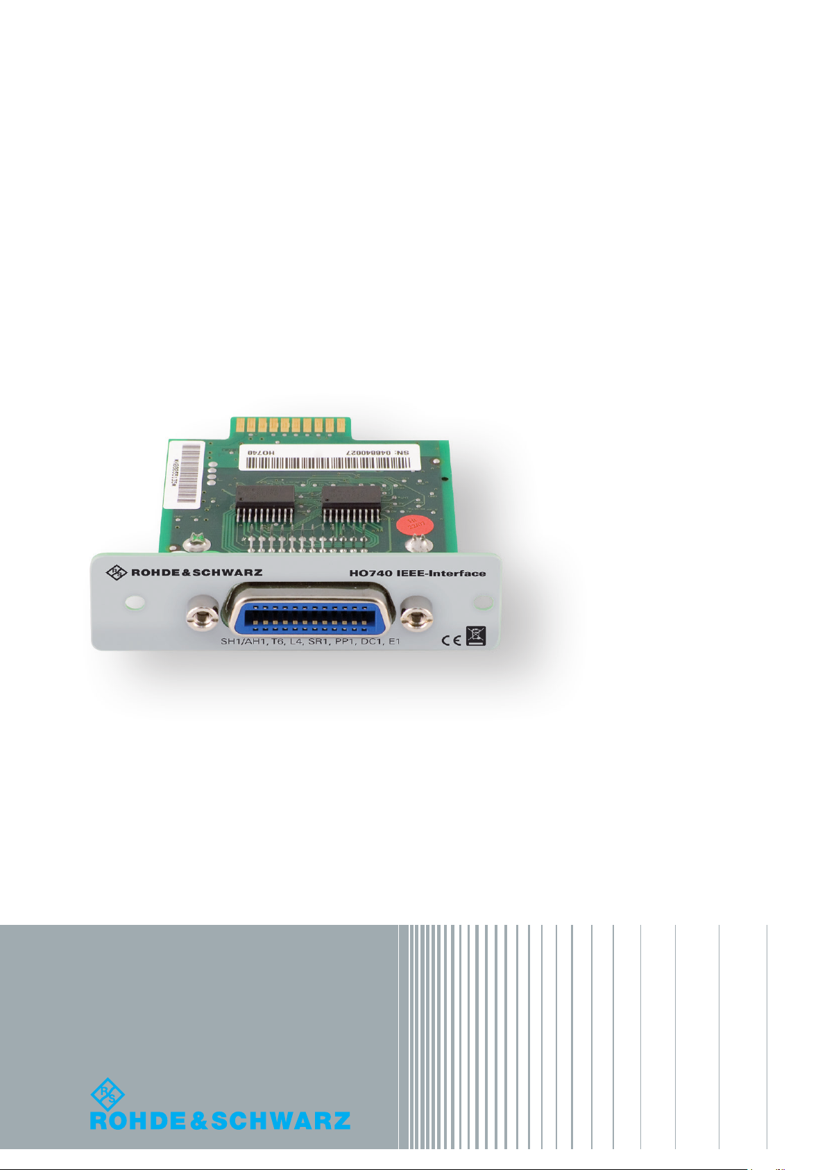
R&S®HO740 ist eine IEEE-488.2 (GPIB) Schnittstelle, die
die Einbindung von HAMEG Combi-Oszilloskopen HM1008
(-2), HM1508 (-2), HM2008, den Mixed Signal Oszilloskopen der R&S®HMO Serie, den Arbitrary-Funktionsgeneratoren der R&S®HMF Serie, den Netzgeräten der R&S®HMP
Serie, sowie den Spektrumanalysatoren der R&S®HMS(-X)
Serie in automatische Testsysteme ermöglicht.
Als GPIB-USB Adapter empfehlen wir die Verwendung eines
National Instruments Adapters (NI-USB-GPIB HS).
1.3 Firmware CombiScope
Vor dem Einbau der R&S®HO740 Schnittstelle muss
unbedingt geprüft werden, welche Firmwareversion das
Combi-Oszilloskop aufweist. Sie wird beim Einschalten des
Combi-Oszilloskops angezeigt (Version: .....), wenn Kurz-
start Aus vorliegt. Zur Kurzstart-Einstellung gelangt man
mit Betätigen der SETTINGS-Taste, wenn im Menü Einstellungen die Funktions-Taste Allgemeines betätigt wird.
Mit der Funktions-Taste Kurzstart kann von An auf Aus
geschaltet werden, so dass beim nächsten Einschalten die
Firmwareversion anzeigt wird.
Wird als Firmwareversion 05.105-yy.yyy oder eine höhere
Version angezeigt, kann mit dem Einbau der R&S®HO740
Schnittstelle fortgefahren werden. Liegt eine Firmwareversion unter 05.105-yy.yyy vor, muss erst ein Firmware-Update erfolgen, da andernfalls die R&S®HO740 Schnittstellenkarte nicht erkannt wird. Im Falle einer Firmwareversion
kleiner als 05.105-yy.yyy, laden Sie bitte die aktuelle Firmware von www.hameg.com herunter und aktualisieren das
Combi-Oszilloskop. Die Installation der Oszilloskop-Firmware erfolgt über die Schnittstellen HO710, R&S®HO720
oder R&S®HO730.
1.4 Firmware andere Geräte
Bei allen anderen Geräten (Serie R&S®HMO, R&S®HMS(-X),
R&S®HMF, R&S®HMP) wird die Schnittstelle von der Firmware erkannt.
An der Schnittstelle bendet sich eine IEEE-488-Buchse,
in das ein IEEE-488-Verbindungskabel eingesteckt werden
kann. Über das Kabel wird die Verbindung zu einem IEEE488-Controller (Steuereinheit eines IEEE-488-Bussystems)
hergestellt. Als IEEE-488-Controller kann ein PC dienen,
der mit einer entsprechenden Steckkarte ausgerüstet ist.
Soll ein IEC-625-Kabel verwendet werden, ist ein pas-
Abb. 1.1: HO740 Schnittstelle
Wie die GPIB Schnittstelle im Messgerät aktiviert und welche
Parameter ggf. eingestellt werden müssen, entnehmen Sie bitte
dem Handbuch des jeweiligen Messgeräts.
3
Page 4
Allgemeine Hinweise
2 Einbau der
Schnittstellenkarte
Die folgende Einbaubeschreibung ist beispeilhaft an einem
CombiScope beschrieben, gilt aber prinzipiell für alle kompatiblen Geräte.
Die im Folgenden beschriebenen Arbeiten dürfen nur ausgeführt
werden, wenn das Netzkabel nicht mit dem Messgerät verbunden
ist und alle Leitungen von den Messeingängen entfernt sind.
Um Beschädigungen der Schnittstelle beim Aus- und Einbau zu
vermeiden, sollten Sie zuerst das Messgerät mit einer Hand an
einer Rückwandbefestigungsmutter berühren, um damit einen
Potentialausgleich zwischen Ihrem Körper und dem Messgerät
durchzuführen. Halten Sie diese Verbindung aufrecht, während
Sie die Schnittstelle aus- oder einbauen.
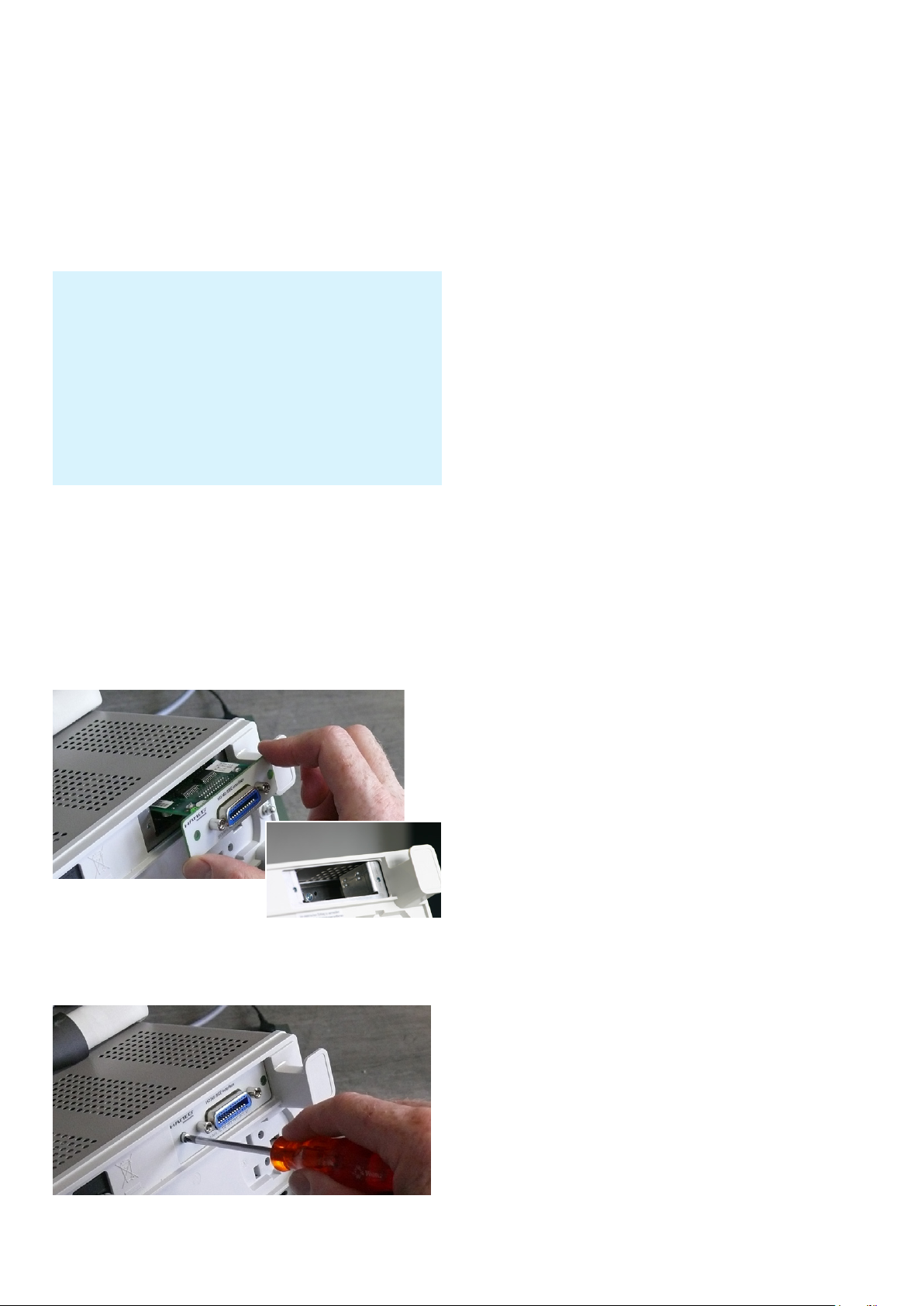
Berühren Sie die Schnittstelle nur an dem Befestigungsblech und entfernen Sie die beiden Befestigungsschrauben. Ziehen Sie die Schnittstelle am Befestigungsblech
oder via angeschlossenem Kabel heraus.
Führen Sie die Schnittstellenkarte in die dafür vorgesehene
Öffnung ein, damit die Leiterplatte in die auf beiden Seiten
erkennbare Führung geschoben wird und drücken diese
ganz hinein.
Abb. 2.1: Einsetzen der neuen
Schnittstellenkarte
Befestigen Sie die Schnittstellenkarte mit den vorher entfernten Befestigungsschrauben.
3 Schnittstellen-
Funktionen und
Einstellungen
3.1 Flusssteuerung (SH1, AH1)
Die Flusssteuerung auf der Sende- und Empfangsseite
(SH = Source Handshake / AH = Acceptor Handshake) ist
für alle weiteren Funktionen, inklusive der Übermittlung
von busspezischen Steuerungsdaten, notwendig und
wird deshalb unterstützt. Eine erweiterte Flusssteuerung
mit der Möglichkeit der vereinfachten Signalisierung ist
nicht implementiert.
3.2 Senden und Empfangen von Daten (T6, L4)
Das Gerät ist in der Lage, Daten zu senden bzw. zu empfangen, wenn die entsprechende Funktion (T = Talker /
L = Listener) vom steuernden Gerät aktiviert wurde. Zur
Adressierung beider Funktionen des Gerätes wird die gleiche primäre Basisadresse verwendet. Sekundäre Adressen werden nicht unterstützt. Die Modi TAL K ONLY und
LISTEN ONLY sind nicht aktivierbar.
3.3 Statusinformationen (SR1, PP1)
Statusinformationen der Schnittstelle sind sowohl nacheinander (Serial Poll) als auch gleichzeitig von mehreren
Geräten (PP = Parallel Poll) am BUS abfragbar. Für die parallele Abfrage werden alle notwendigen Einstellungen der
Schnittstelle vom steuernden Gerät über den IEEE-488BUS vorgenommen. Bei entsprechender Konguration der
interne Registermasken des Gerätes (siehe SCPI-Programmierbefehle) signalisiert die Schnittstelle dem steuerndem
Gerät interne Statusänderungen (SR – Service Request).
Damit entfällt das Warten auf die Antwort des Gerätes
oder aber das wiederholte Abfragen des Gerätestatus.
Die entsprechenden Einstellungen des Gerätes sind nach
jedem Einschalten erneut vorzunehmen.
3.4 Initialisierung der Kommunikation (DC1)
Die busspezischen Steuerkommandos DCL (Device Clear)
und SDC (Selected Device Clear) werden vom internen
Management unabhängig von anderen, eventuell noch abzuarbeitenden SCPI-Kommandos, bearbeitet (DC = Device
Clear). Innerhalb des Gerätes wird die SCPI-Befehlsbearbeitung entsprechendend dem Standard IEEE-488 neu
initialisiert, die Ausführung der aktuellen Kommandos wird
unterbrochen und die Datenpuffer werden gelöscht. Die
Flusssteuerung signalisiert erst nach vollständiger Abarbeitung dieser Kommandos die Bereitschaft zur Übertragung
neuer Daten.
Abb. 2.2: Festschrauben der Schnittstellenkarte
4
Page 5

Allgemeine Hinweise
3.5 Nicht unterstützte Funktionen (RL0, DT0, C0, CF0)
Die folgenden Funktionen werden nicht unterstützt:
❙ Umschaltung zwischen lokaler und Fernbedienung mit
der Möglichkeit zur Sperrung der lokalen Bedienelemente
(RL = Remote Local)
❙ Externer Start der Basisfunktion des Gerätes
(DT = Device Trigger)
❙ Einsatz als steuerndes Gerät am BUS (C = Controller)
❙ Berücksichtigung der vom steuernden Gerät
angegebenen Kabellänge am IEEE488-BUS
(CF = Conguration)
Die Sperrung der lokalen Bedienelemente ist je nach Gerätetyp
mittels SCPI-Befehl (siehe SCPI-Programmierbefehle) möglich.
3.6 Bustreiber (E1)
Die Daten- und Steuerleitungen des IEEE-488-Busses werden durch Treiber mit Open Collector-Ausgängen gesteuert. Damit sind laut Standard IEEE488.1 eine Datenrate von
bis zu 250000 Bytes pro Sekunde möglich.
3.7 Adressierung von IEEE-488-Geräten
Der Standard IEEE-488 speziziert den Aufbau der Adressen für Sende- und Empfangsfunktionen eines Gerätes.
Dabei können für unterschiedliche Gerätefunktionen wie
zum Beispiel Sende- und Empfangsfunktion oder mehrere
unterschiedliche Sende- bzw. Empfangsfunktionen jeweils
separate Adressen vergeben werden. Diese Adressen
können sich aus dem primären und dem sekundären Anteil
zusammensetzen. Beide Teile besitzen einen variablen
Anteil (5 Bit) für die eigentliche Adresse und eine feste
Gruppenzuordnung (2 Bit). Das 8. Bit wird nicht benutzt.
Damit ist für die Geräteadressen ein Bereich von 0 bis
30 (00h bis 1Eh) verfügbar. Die Adresse 31 (1Fh) hat eine
spezielle Bedeutung. Sie wird verwendet, um die Funktion
der jeweils adressierten Gruppe für alle Geräte am BUS zu
deaktivieren (UNL = Unlisten / UNT = Untalk).
mit dem INTENS-Knopf von 0 bis 30 wählbar. Es ist darauf
zu achten, dass diese Adresse von keinem anderen Gerät
benutzt wird.
Serie R&S®HMS(-X), R&S®HMP, R&S®HMF, R&S®HMO
Nach dem Bestätigen der Taste SETUP bzw. MENU und
der Menütaste SCHNITTSTELLE bzw. Auswahl des Menüpunktes INTERFACE mit dem Drehgeber wird das Schnittstellenmenü aufgerufen. Die Schnittstelle IEEE-488 ist bereits aktiviert. Unter PARAMETER (bzw. SETTINGS bei der
R&S®HMP Serie) kann nun die Adresse mit dem Drehgeber
(bei Serie HMO im CURSOR/MENU Bereich) von 0 bis 30
ausgewählt werden. Es ist darauf zu achten, dass diese
Adresse von keinem anderen Gerät benutzt wird.
Folgende Adressgruppen sind speziziert:
❙ Primäre Adressen für Empfangsfunktionen (Kodierung: 20h)
❙ Primäre Adressen für Sendefunktionen (Kodierung: 40h)
❙ Sekundäre Adressen (Kodierung: 60h).
Damit ergibt sich zum Beispiel die vollständige primäre
Adresse der Empfangsfunktion eines Gerätes mit der Basisadresse 8 zu 40 (28h).
3.8 Einstellung der primären Geräteadresse
Combi-Oszilloskope
Die Wahl der Adresse ist nur möglich, wenn, wie unter
Kap. 1.3 Firmware Combi-Oszilloskope beschrieben, das
Oszilloskop mit der Firmwareversion 05.105-yy.yyy oder
höher arbeitet und die Schnittstelle R&S®HO740 eingebaut
ist. Nach dem Betätigen der Taste SETTINGS, zeigt das
Oszilloskop das Menü Einstellungen an. Mit der Funktionstaste Schnittstelle wird das Menü Einstellungen Schnittstelle aufgerufen. Daraus resultiert die Anzeige IEEE-488
und mit höherer Helligkeit Adresse x. Die Adresse (x) ist
5
Page 6

Anwendungen
4 Anwendungen
4.1 Hameg CombiScopes
Die Schnittstelle R&S®HO740 kann in Verbindung mit der
Anwendersoftware HMExplorer zur Übertragung von
Einstellungen, Daten und Bildschirmausdrucken sowie der
Eingabe von Fernsteuerbefehlen genutzt werden (nur im
Digitalbetrieb der CombiScopes).
4.2 R&S®HMO Serie
Für die R&S®HMO Serie steht die Software HMExplorer
zum kostenlosen Download auf der Rohde & Schwarz
Webseite zur Verfügung. Die genauen Funktionen (Übertragen von Einstellungen, Daten und Bildschirmausdrucken, Eingabe von Fernsteuerbefehlen in eine Kommandozeile) und die notwendigen Einstellungen entnehmen Sie
bitte dem Software-Manual. Eine Liste der SCPI Program-
mierbefehle nden Sie ebnfalls auf der Rohde & Schwarz
Homepage.
4.3 R&S®HMS(-X) Serie
Für die R&S®HMS(-X) Serie steht auf der Rohde & Schwarz
Webseite die HMExplorer Software für PreCompliance
EMV Messungen und Datenübertragung zum kostenlosen
Download zur Verfügung. Die genauen Möglichkeiten
(EMV PreCompliance Test, Übertragen von Einstellungen,
Daten und Bildschirmausdrucken, Eingabe von Fernsteuerbefehlen in eine Kommandozeile) und die notwendigen
Einstellungen entnehmen Sie bitte dem Software-Manual.
4.4 R&S®HMF / R&S®HMP Serie
Für die R&S®HMF- und R&S®HMP Serie steht auf der
Rohde & Schwarz Webseite die HMExplorer Software
für die Erstellung und Übertragung von Arbiträrkurven
zum kostenlosen Download zur Verfügung. Die genauen
Möglichkeiten (Erstellen und Anpassen von Arbiträrkurven,
Übertragen von Einstellungen, Daten und Bildschirmausdrucken, Eingabe von Fernsteuerbefehlen in eine Kommandozeile) und notwendigen Einstellungen entnehmen
Sie bitte dem Software-Manual.
6
Page 7

Content
1 General Information 8
1.1 Safety hints 8
1.2 Interface Description 8
1.3 Firmware CombiScope 8
1.4 Firmware for other instruments 8
2 Fitting Instruction 9
3 Interface Functions and Settings 9
3.1 Flow control (SH1, AH1) 9
3.2 Transmission and reception of data (T6, L4) 9
3.3 State information (SR1, PP1) 9
3.4 Communication initialisation (DC1) 9
3.5 Not supported functions (RL0, DT0, C0, CF0) 9
3.6 BUS driver (E1) 10
3.7 Addressing of IEEE-488 devices 10
3.8 Selection of Primary Address 10
Content
4 Applications 10
4.1 CombiScopes 10
4.2 R&S®HMO series 10
4.3 R&S®HMS(-X) series 10
4.4 R&S®HMF / R&S®HMP Serie 10
7
Page 8

General Information
1 General Informa-
tion
1.1 Safety hints
Fitting or exchanging of an interface must not be made unless the
instrument is switched off and not connected to line (mains).
During operation the interface opening must be closed.
All interface connections are galvanically isolated from the
instrument to avoid so called “hum” loops by multiple earthing (in
this case by the PC).
Measurement at high potentials is prohibited and endangers the
instrument, the interface and all equipment connected to the
interface.
If the safety rules are disregarded, any damage to we will
not take any responsibility for damage to people or equipment of other make.
The NI-USB-GPIB HS adapter from National Instruments is
recommended as GPIB-USB adapter.
1.3 Firmware CombiScope
For CombiScopes [HM1008 (-2), HM1508 (-2), HM2008] it
is absolutely necessary to check the oscilloscope rmware version before tting the Interface R&S®HO740. The
rmware version already on the scope is displayed after
switching on if Quick Start is off. The Quick Start function
can be changed after pressing the SETTINGS pushbutton
and calling Misc..
If the rmware version is 05.105-yy.yyy or higher, continue
the interface tting as described under item 2 (HO740 tting instruction). In case rmware versions below 05.105yy.yyy, R&S®HO740 will not be recognized and a rmware
update is required. If the rmware version is below 05.105yy.yyy, please download the latest rmware at www.
hameg.com and update the oscilloscope.
1.4 Firmware for other instruments
With the other instruments (R&S®HMO, R&S®HMS(-X),
R&S®HMP, R&S®HMF series) the interface will be reco-
gnized by the rmware.
1.2 Interface Description
The R&S®HO740 is an IEEE-488.2 (GPIB) interface enabling
the integration of HAMEG CombiScopes HM1008(-2),
HM1508(-2), HM2008, the Mixed Signal Oscilloscopes
of the R&S®HMO series, the Arbitrary Function Generators of the R&S®HMF series, the Power Supplies of the
R&S®HMP series, as well as the spectrum analyzer series
R&S®HMS(-X) into automatic test systems.
The interface has an IEEE-488 socket. To establish a connection to an IEEE-488 controller (control unit of an IEEE488 bus system) a IEEE-488 cable is required. A PC can
be used as IEEE-488 controller, which is equipped with a
corresponding plug-in card. If an IEC-625 cable is used, a
suitable plug adapter is required.
The R&S®HO740 interface operates in „device“ mode. It
receives commands from a controller, delivers them to the
instrument and transmits signal data to the controller. The
data is transferred bidirectionally in parallel form.
Please refer to the instrument user manual for detailed information about activating the GPIB interface and interface parameters.
Fig. 1.1: HO740 Interface
8
Page 9

General Information
2 Fitting Instruction
The following tting instruction shows a CombiScope, but
the interface tting is also the same for the other compati-
ble instruments.
The following procedure has only to be carried out, if the mains
(line) power cable is not connected to the instrument. All test
leads have be removed from the measuring inputs.
To avoid interface damage during removing and tting by elec-
trostatic discharge, please link a metal part of the instrument to
equalise potentials between instrument and your body. Maintain
this connection during the tting/removing.
Only touch the interface at its mounting panel and remove
the fastening screws. Pull out the interface via mounting
panel or connected interface cable. Insert the interface
card via the visible guide bars into the interface card slot
and push it in completely.
Fig. 2.1: Fitting the interface card
3 Interface Functions
and Settings
3.1 Flow control (SH1, AH1)
The ow control is for both transmitter and receiver (SH =
Source Handshake / AH = Acceptor Handshake) is required for all further functions incl. the transmission of bus
specic control data and therefore supported. Extended
ow control with the possibility of a simplied indication is
not implemented.
3.2 Transmission and reception of data (T6, L4)
The instrument is able to transmit and receive data if the
corres-ponding function (T = Talker / L = Listener) has
been activated by the control device. For addressing of
both functions the same primary basic address has to be
used. Secondary addresses are not supported. The modes
Talk Only and Listen Only cannot be activated.
3.3 State information (SR1, PP1)
Interface state information can be polled in sequential
mode (Serial Poll) as well as simultaneously from several
devices (PP = Parallel Poll) from the bus. All required interface settings for parallel polling are made by the control
device via the IEEE488-BUS. If the conguration of the
device enable register is applicable (note SCPI programming commands) the interface indicates the control device
internal state changes (SR = Service Request). This avoids
waiting time for the instrument’s reply or the recurrent
query for the instrument state. The required device settings must be made each time the device is switched on.
Fit the interface with the fastening screws previously
removed.
Fig. 2.2: Fastening screws
3.4 Communication initialisation (DC1)
Bus specic control commands DCL (Device Clear) and
SDC (Selected Device Clear) will be processed by the
internal management, independent of other SCPI commands still to be processed (DC = Device Clear). Within
the instrument the SCPI command processing will be
newly initiated, the execution of current commands will be
interrupted, and the data buffer will be deleted. The ow
control cannot indicate the acceptance for new data transmission until these data have been completely processed.
3.5 Not supported functions (RL0, DT0, C0, CF0)
The following functions are not supported:
❙ Switch over between local and remote with the
opportunity to lock local controls (RL = Remote Local)
❙ External start of the instruments basic functions
(DT = Device Trigger)
❙ Bus controller operation (C = Controller)
❙ Considering the control device IEEE-488 BUS cable
length (CF = Conguration)
Local controls can be locked by SCPI commands depending on
the instrument type (please refer to the SCPI commands).
9
Page 10

Applications
3.6 BUS driver (E1)
The IEEE-488 BUS data and control lines are controlled by
drivers with open collector outputs. As to be seen in IEEE-
488.1 standard, this enables a data rate of up to 250000
Bytes per second.
3.7 Addressing of IEEE-488 devices
The IEEE-488 standard species the address structure for
transmitter and receiver functions of a device. It allows you
to assign separate addresses for different device functions such as transmission and receiving functions or for
several different transmission and receiving functions as
appropriate. These addresses can consist of a primary and
a secondary part. Both have a variable part (5 bit) for the
real address and a xed group allocation (2 bit). The 8th bit
is not used. Thus instrument addresses in the range from
0 to 30 (00h to 1Eh) are available. The address 31 (1Fh) has
a special function. It is used to deactivate the function of
an addressed group on the bus (UNL = Unlisten / UNT =
Untalk).
The following address groups are specied:
❙ Primary addresses for receiver function (coding: 20h)
❙ Primary addresses for transmitter function (coding: 40h)
❙ Secondary addresses (coding: 60h).
4 Applications
4.1 C omb i S c op e s
The interface R&S®HO740 can be used with the application
software HMExplorer in oder to transfer data, setups and
screenshots (in digital mode of the combiscope only).
4.2 R&S®HMO series
For the R&S®HMO series the HMExplorer software is
available for free on the Rohde & Schwarz website. Please
refer to the software manual concerning the necessary
settings and the offered feature. (e.g. transfer of settings,
data and screenshots, command line for sending remote
commands). The SCPI remote commands manual you can
nd on www.hameg.com.
4.3 R&S®HMS(-X) series
For the R&S®HMS(-X) series the HMExplorer software is
available for free on the Rohde & Schwarz website. Please
refer to the software manual concerning the necessary
settings and the offered feature. (e.g. EMC PreCompliance
measurements, transfer of screenshots, command line for
sending remote commands). The SCPI remote commands
manual you can nd on the Rohde & Schwarz homepage.
E.g. the complete primary address of the receiver function
of a device with the basic address 8 will be 40 (28h).
3.8 Selection of Primary Address
CombiScopes
The selection of an address is only possible if, as described
under Chap. 1.3: Firmware CombiScope a rmware version
05.105-yy.yyy or higher is present in the scope and the
interface HO740 is tted. Pressing the SETTINGS pushbutton calls the Settings menu. The function key Interface
opens the submenu Settings Interface, which displays
IEEE-488 and highlights Address x. The address (x) can
be selected from 0 to 30 by turning the INTENS knob. It
is important to ensure that this address is not used by any
other device on the bus.
R&S®HMS, R&S®HMP, R&S®HMF, R&S®HMO series
After pressing the SETUP resp. MENU button and choosing the menu item INTERFACE the interface menu is
displayed. The interface IEEE 488 is already selected. With
the menu PARAMETER (resp. SETTINGS with R&S®HMP
series) the GPIB adress can be selected from 0 to 30 with
the knob (R&S®HMO series with the knob in the CURSOR/
MENU area) on the front panel. It is important to ensure
that this address is not used by any other device.
4.4 R&S®HMF / R&S®HMP Serie
For the R&S®HMF / R&S®HMP series the HMExplorer software is available for free on the Rohde & Schwarz website.
Please refer to the software manual concerning the necessary settings and the offered feature. (e.g. generate and
transfer of arbitrary waveforms, transfer of screenshots,
command line for sending remote commands). The SCPI
remote commands manual you can also nd on the Rohde
& Schwarz homepage.
10
Page 11

General Information
© 2015 Rohde & Schwarz GmbH & Co. KG
Mühldorfstr. 15, 81671 München, Germany
Phone: +49 89 41 29 - 0
Fax: +49 89 41 29 12 164
E-mail: info@rohde-schwarz.com
Internet: www.rohde-schwarz.com
Customer Support: www.customersupport.rohde-schwarz.com
Service: www.service.rohde-schwarz.com
Subject to change – Data without tolerance limits is not binding.
®
is a registered trademark of Rohde & Schwarz GmbH & Co. KG.
R&S
Trade names are trademarks of the owners.
5800.5482.02 │ Version 01 │HO740
11
 Loading...