

Page 1

HZ 115
Differential probe for oscilloscopes
1500 V input voltage max.
30 MHz bandwidth
x 100 and x 1000 attenuation
> 50 dB CMRR (1MHz)
User-friendliness through a
Automatic Switch-off
Beep appears when overrange
Low battery indication
Battery operation with external
microcontroller
supply option
C E
IEC 1010 Cat IIIIEC 1010 Cat III
IEC 1010 Cat III
IEC 1010 Cat IIIIEC 1010 Cat III
Page 2
ContentsContents
Contents
ContentsContents
Symbols usedSymbols used
Symbols used
Symbols usedSymbols used
1. Safety precautions
2. Items supplied with the probe
3. Introduction to the differential probe
4. Technical features.
5. Using the probe
6. Maintenance and repair
7. Examples of differential probe applications
1.Saf1.Saf
ety prety pr
1.Saf
ety pr
1.Saf1.Saf
ety prety pr
Prior to using the differential probe for the first time, read the following carefully :
The probe must only be used by qualified personnel.
Earthing the probe : This probe is designed to be Class 1 (connected to a protective conductor) so, apply carefully the
following
Use only high quality accessories which conform to safety standards.
Never open the probe whilst the input leads are connected.
Never exceed the maximum input voltage of 1500 V (DC + AC peak), (IEC 1010-1 Cat. III). When using equipment with a reted of
Do not expose the probe to humidity, steam or an aggressive or explosive environment.
Keep the case and the connection leads in a clean condition and prevent humidity or liquid from being able to penetrate inside
Do not use the probe if there is any reason to think that it is not operating properly or that it is faulty.
The mains power supply must conform to the standards in force.
If the probe is not to be used for a prolonged period, remove the battery, so that it will not damage the battery compartment.
2. Items supplied with the pr2. Items supplied with the pr
2. Items supplied with the pr
2. Items supplied with the pr2. Items supplied with the pr
connecting procedure: By means of the BNC output socket, connect the probe to the oscilloscope in order to earth it. It is
therefore necessary to check that the oscilloscope itself is connected to earth via a lead which conforms to regulations.
Then connect the probe to the oscilloscope, prior to connecting the leads to the item to be tested.
It is imperative not to disconnect the probe from the oscilloscope until after the test leads have been disconnected.
1000 V CAT III they never exceed the maximum input voltage of 1400 V (DC + AC peak).
the probe or its component parts.
The differential probe is supplied with the following : 1 Differential probe 1 9 V monobloc battery 6LF22
ecautionsecautions
ecautions
ecautionsecautions
obeobe
obe
obeobe
The following safety signs are used on the probe
and in these instructions:
Caution, dang Caution, dang
Caution, dang
Caution, dang Caution, dang
2 safety test tips 1 operating instructions
Caution, dangCaution, dang
Caution, dang
Caution, dangCaution, dang
R R
ead instread instr
R
ead instr
R R
ead instread instr
erer
ous vous v
er
ous v
erer
ous vous v
er !er !
er !
er !er !
uctions !uctions !
uctions !
uctions !uctions !
oltaolta
olta
oltaolta
gg
e!e!
g
e!
gg
e!e!
Page 3
3. Introduction to the differntial probe
4. T4. T
4. T
4. T4. T
ecec
hnical chnical c
ec
hnical c
ecec
hnical chnical c
harhar
acteristicsacteristics
har
acteristics
harhar
acteristicsacteristics
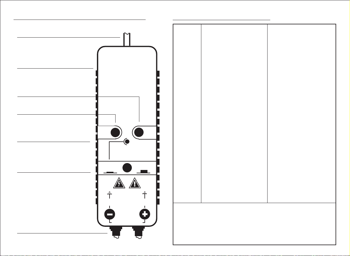
OUTPUT
max. ± 1,5 V
Socket for external supply
12 V DC / 30 mA
OFF button
ON button
LED
yellow - x 100
red - x 1000
flashes- U batt < 6 V
Attenuation switch
pressed - x 100
not pressed - x 1000
The srews for opening the
probe are located on the rear
face.
Differential input
(Safety leads)
>
DIFFERENTIAL PROBE
>
HZ 115HZ 115
HZ 115
HZ 115HZ 115
>
>
POWER
X 100 X1000
>
1500Vpeak
max 1500Vpeak
>
>
OFFON
1500Vpeak
Input Differential input voltage max. ± 1500V (DC+AC
Common mode input voltage ± 1500V (DC+AC
to earth. Warning: both above
conditions must be respected
simultaneously.
When using equipment to 1000V ± 1400V (DC+AC
Safety IEC1010-2-031, Insulation: class1
Degree of pollution 2, Indoor use, altitude < 2000m
Installation category of input CAT III (*); 1500V max. to earth
Operating temperature 0°C to +40°C
Storage temperature -10°C to +60°C
Relative humidity 80 % RH at 40°C
Input impedance 60MΩ ||1.5 pF
Attenuation x 100 and x 1000
Accuracy after 1 min. ± 3% (18°C - 30°C) I
Frequency Bandwidth at x 100 20 MHz
Bandwidth at x 1000 30 MHz
Rise time at x 100 17.5 nsec
Rise time at x 1000 12 nsec
Output Output voltage max. ± 1.5 V (1MΩ)
Output impedance 50 Ω
Noise max. 1.5 mV
Common mode rejection ratio DC: 70 dB AC: >50dB (at 1 MHz)
Supply Battery 9V block
Low battery indication LED flashes at U batt < 6 V
Optional power supply 12V DC / 35 mA
Operating time on one battery approx. 16 hours
Battery switch-off automatic, after 10 minutes
Accessories 2 safty test tips red and black
Dimensions Case (LxWxH) 157 x 60 x 26 mm
Weight 300 g with battery
Material ABS, internal screening
Output cable length 50 cm
EMC:
This instrument has been designed in conformity with EMC standards in use and the
compatibility has been tested regarding the following standards - EN 61326
(IEC 1326). The product herewith complies with the requirements of the low voltage
directive 73/23/EEC and the EMC directive 89/336/EEC amended by 93/687EEC.
(*) Overvoltage category III is defined as follow: Fixed installation equipment
(Examples: Industrial apparatus permanently connected to a fixed installation)
peak
peak
peak
)
)
)
Page 4

5. Using the pr5. Using the pr
5. Using the pr
5. Using the pr5. Using the pr
BefBef
oror
Bef
or
BefBef
oror
prpr
ecautionary measurecautionary measur
pr
ecautionary measur
prpr
ecautionary measurecautionary measur
obeobe
obe
obeobe
e using the dife using the dif
e using the dif
e using the dife using the dif
ff
erer
ential prential pr
f
er
ential pr
ff
erer
ential prential pr
es aes a
es a
es aes a
obe fobe f
obe f
obe fobe f
t the bet the be
t the be
t the bet the be
or the for the f
or the f
or the for the f
ginning ofginning of
ginning of
ginning ofginning of
irir
st timest time
ir
st time
irir
st timest time
these instr these instr
these instr
these instr these instr
, r, r
, r
, r, r
ead caread car
ead car
ead caread car
uctionsuctions
uctions
uctionsuctions
efully the section on theefully the section on the
efully the section on the
efully the section on theefully the section on the
..
.
..
Inser Inser
Inser
Inser Inser
Before using the differential probe for the first time, the battery supplied with the device must be inserted in
the battery compartment and connected up by means of the clip.
If the LED lamp (battery indicator) flashes during operation, the voltage of the battery has dropped to
approximately 6 V. In order to ensure that the probe is operating correctly, it will then be necessary to
replace the battery.
To insert or replace the battery, remove the three screws on the rear face of the case and then open the
probe. If necessary, the old 9 V battery can then be removed and insert the new one in the compartment.
Always ensure not to damage or move the electronic components, in particular the control device.
After inserting the new battery, close the case and tighten the three fastening screws.
Usign an eUsign an e
Usign an e
Usign an eUsign an e
Using the socket on the side of the probe, it is possible to connect the device to an external power supply.
The internal battery is then disconnected and the battery saving automatic switch-off does not operate,
indicated by a beep .
A A
A mains transformer, for example, can be used for the external power supply. The power supply voltage must
A A
lie within the range of 9 - 16 V DC. The current consumption will be approximately 35 mA. Take into account
the fact that the output voltage of some supplies considerably exceeds their nominal value !
Only use on external power supply that conforms with all the safety and EMC standards in force.
ting or rting or r
ting or r
ting or rting or r
At the time of inserting or replacing the battery, the input leads must not be connected to an
item to be tested! Never operate the probe with the case open.
ee
placing the 9 V baplacing the 9 V ba
e
placing the 9 V ba
ee
placing the 9 V baplacing the 9 V ba
xternal powxternal pow
xternal pow
xternal powxternal pow
er supplyer supply
er supply
er supplyer supply
tteryttery
ttery
tteryttery
Page 5

Connecting the pr Connecting the pr
Connecting the pr
Connecting the pr Connecting the pr
Prior to connecting the probe, read the section on the safety precautions at the beginning of these
instructions! Connect the output of the probe to the input of the oscilloscope, with the coaxial lead inserted
into the BNC socket. The input impedance of the oscilloscope must be 1 M
connection it is not advisable to extend the cable considerably.
In the case of using an oscilloscope incorporating a 50
by half. It should also be taken into account the fact that consumption may also increase. In the case of a
low impedance connection, it is possible to extend the cable without difficulty.
Use of the safety leads ensures reliable measurements up to a maximum voltage of ±1500V DC + peak AC.
Should accessories be used which were not supplied with the probe, it is essential to check that they
conform to safety standards!
T T
est equipment risk assesmentest equipment risk assesment
T
est equipment risk assesment
T T
est equipment risk assesmentest equipment risk assesment
Users of this equipment and or their employers are reminded than Health and Safety Legislation require
them to carry out a valid risk assesment of all electrical work so as to identify the potential sources of
electrical danger and risk of electrical injury such as from inadvertent short circuits. Where the assesment
show that the risk is significant then the use of fused test leads constructed in accordance to the HSE
guidance note GS38 „Electrical Test Equipment for use by Electricians“ should be used.
obeobe
obe
obeobe
ΩΩ
Ω. In view of the high impedance
ΩΩ
ΩΩ
Ω input, the output voltage of the probe is reduced
ΩΩ
Switc Switc
Switc
Switc Switc
hing the prhing the pr
hing the pr
hing the prhing the pr
The probe is switched on by pressing briefly on the ON button. The operating condition is indicated by the
LED LED
LED lamp lighting up and a short beep. Colour of the LED indicats attenuation: yellow - x100, and red - x1000.
LED LED
The device can be switched off by pressing briefly on the OFF button.
In order to increase the life of the battery, the device switches itself off automatically after an operating time
of 10 minutes. The automatically switch off is independent of the input signal. If the ON button is pressed
again before the end of this period, the operating time is again reset to 10 minutes. It is possible, to switch
off the automatic shutoff timer by pressing the ON button longer then 1 sec. The automatic shutoff facility is
cancelled when an external supply is connected.
obe on and ofobe on and of
obe on and of
obe on and ofobe on and of
ff
f
ff
Page 6

Button or operation result beep
ON briefly device on 1 x (2 x when ext. supply is indicated)
ON briefly, when divice is on auto off reset 1 x
ON longer then 1 sec auto off off 2 x
external supply on auto off off 2 x
external supply off auto off on and reset 1x
auto off after 10 min device off 3 x 2
OFF briefly device off 1 x
input voltage >150V at x100 continual
input voltage >1500V at x1000 continual
Choice ofChoice of
Choice of
Choice ofChoice of
The probe offers the choice of two attenuation factors : x 100 and x1000.
For an attenuation factor of x 100 (selector depressed, LED is lighting yellow), the voltage at the inputs is
equal to the voltage displayed on the oscilloscope x 100.
For an attenuation factor of x 1000 (selector not depressed, LED is lighting red), the voltage at the inputs is
equal to the voltage displayed on the oscilloscope x 1000.
PrPr
ocedurocedur
Pr
ocedur
PrPr
ocedurocedur
- Check the mains earth connection to the oscilloscope
- Connect the probe to the oscilloscope.
- Adjust the vertical sensitivity on the oscilloscope (V/div.).
- Select the attenuation factor on the probe (x 100 or x 1000).
- Switch the probe ON.
- If necessary, adjust the reference line on the oscilloscope.
- Connect the test leads to the item to be tested.
6. Maintenance and r6. Maintenance and r
6. Maintenance and r
6. Maintenance and r6. Maintenance and r
The differential probe does not require any special maintenance. If necessary, clean the case with a damp
cloth. Ensure that no moisture enters inside the device.
Do not use the probe if there is any reason to think that it is not operating properly or that it is faulty.
In the case of repair, send the device to the distributor. Do not attempt to service or repair the probe yourself.
a a
ttentten
uaua
ua
uaua
tiontion
tion
tiontion
ee
e
ee
pairpair
pair
pairpair
a
tten
a a
ttentten
e fe f
or using the difor using the dif
e f
or using the dif
e fe f
or using the difor using the dif
ff
erer
ential prential pr
f
er
ential pr
ff
erer
ential prential pr
obeobe
obe
obeobe
Page 7

7. Examples of7. Examples of
7. Examples of
7. Examples of7. Examples of
RR
efef
erer
ence potential and safence potential and saf
R
ef
er
ence potential and saf
RR
efef
erer
ence potential and safence potential and saf
The measuring inputs of a normal mains operated oscilloscope are referenced to mains earth potential because
they are connected, via the oscilloscope power cord, to the mains earth. Also, other exposed metal parts of the
oscilloscope are connected to earth. Therefore, if an oscilloscope is connected to measure live mains circuits
such as switching controllers, thyristors or power MOSFETs then this can cause short circuits damaging the
system components and extreme user safety hazards.
These safety hazards still exist if the oscilloscope earth is
disconnected or if it is powered through a mains isolating
transformer because the oscilloscope input and other metal
parts will be raised to the test circuit voltage.
However, the use of differential probes provides safe single or
multi-channel measuring connections.
Differential probe for safe measurements
dif dif
dif
dif dif
ff
erer
ential prential pr
f
er
ential pr
ff
erer
ential prential pr
etyety
ety
etyety
obe aobe a
obe a
obe aobe a
pplicapplica
pplica
pplicapplica
tionstions
tions
tionstions
The oscilloscope casing may carry lethal voltages
when the ground Iead is detached.
Apart from the danger which exists when taking measurements
with floating potential, further problems arise in multi-channel
measurements because ground connections still exist between
the oscilloscope inputs. Using a differential probe ensures safety.
This probe allows measurements between any two points of a
circuit without a reference point. However, since the output is
related to ground, it can be easily connected to the input of the
earthed oscilloscope.
Page 8

EarEar
th loop cirth loop cir
Ear
th loop cir
EarEar
th loop cirth loop cir
Whilst the ground potential can in principle be used as a common reference point in many cases, it is often
impossible to make reference connections to the same common point. This may create earth loops which means
that a voltage may build up between the ground potential of the investigated circuit and the ground potential of the
oscilloscope. It can be greater than the signal voltage and falsify the measuring result. The use of a differential
probe is frequently the only solution in such cases or when a high common-mode voltage is present.
Highly accurate measurements largely unaffected by
interference voltages can be made thanks to the high
degree of common-mode rejection offered by the differential probe and the possibility of tapping the
measuring voltage direct at the signal source.
cuits and common mode vcuits and common mode v
cuits and common mode v
cuits and common mode vcuits and common mode v
oltaolta
olta
oltaolta
gg
eses
g
es
gg
eses
Example: Voltage at the motor series resistor is
only a fraction of the common-mode voltage which
is superimposed on the measuring voltage.
Differential probe principle
The differential probe expands each oscilloscope input to provide differential input connections
for safe measuring on floating potential circuits. The probe also provides rejection of common
mode signals.
 Loading...