


R&S®ESU
EMI Test Receiver
Test & Measurement
Quick Start Guide
Quick Start Guide
1302.6163.62 – 07

The Operating Manual describes the following R&S®ESU models and options:
● R&S ESU8 (1302.6005K08)
● R&S ESU26 (1302.6005K26)
● R&S ESU40 (1302.6005K40)
● R&S FSU-B9 (1142.8994.02)
● R&S FSP-B10 (1129.7246.03)
The contents of this manual correspond to firmware version 5.74 or higher.
The firmware of the instrument makes use of several valuable open source software packages. For information, see the "Open
Source Acknowledgement" on the user documentation CD-ROM (included in delivery).
Rohde & Schwarz would like to thank the open source community for their valuable contribution to embedded computing.
©
2015 Rohde & Schwarz GmbH & Co. KG
81671 Munich, Germany
Subject to change – Data without tolerance limits is not binding.
®
R&S
is a registered trademark of Rohde & Schwarz GmbH & Co. KG.
Trade names are trademarks of the owners.
The following abbreviations are used throughout this manual:
®
R&S
ESU is abbreviated as R&S ESU.
Basic Safety Instructions
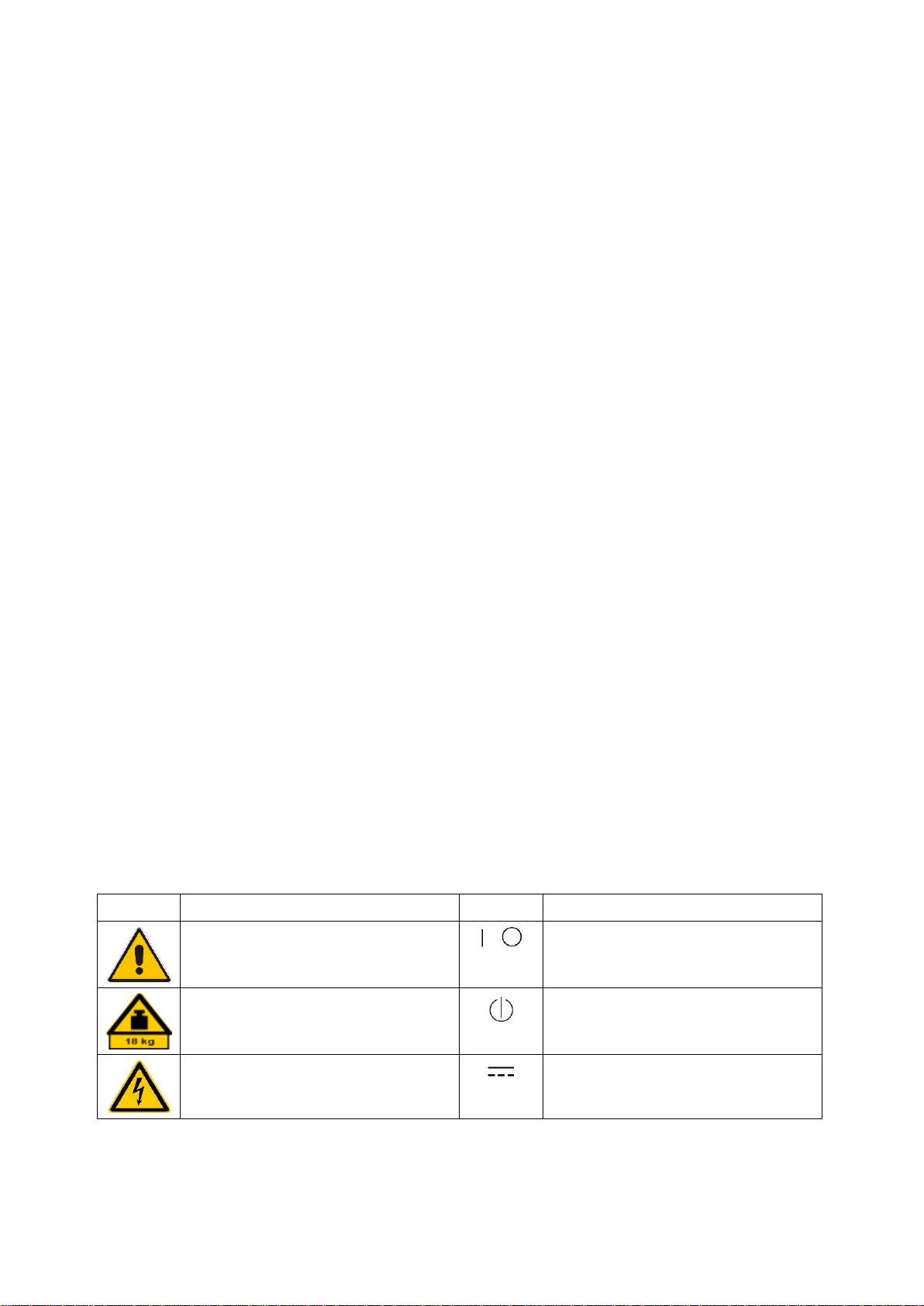
Symbol
Meaning
Symbol
Meaning
Notice, general danger location
Observe product documentation
ON/OFF Power
Caution when handling heavy equipment
Standby indication
Danger of electric shock
Direct current (DC)
Always read through and comply with the following safety instructions!
All plants and locations of the Rohde & Schwarz group of companies make every effort to keep the safety
standards of our products up to date and to offer our customers the highest possible degree of safety. Our
products and the auxiliary equipment they require are designed, built and tested in accordance with the
safety standards that apply in each case. Compliance with these standards is continuously monitored by
our quality assurance system. The product described here has been designed, built and tested in
accordance with the EC Certificate of Conformity and has left the manufacturer’s plant in a condition fully
complying with safety standards. To maintain this condition and to ensure safe operation, you must
observe all instructions and warnings provided in this manual. If you have any questions regarding these
safety instructions, the Rohde & Schwarz group of companies will be happy to answer them.
Furthermore, it is your responsibility to use the product in an appropriate manner. This product is designed
for use solely in industrial and laboratory environments or, if expressly permitted, also in the field and must
not be used in any way that may cause personal injury or property damage. You are responsible if the
product is used for any purpose other than its designated purpose or in disregard of the manufacturer's
instructions. The manufacturer shall assume no responsibility for such use of the product.
The product is used for its designated purpose if it is used in accordance with its product documentation
and within its performance limits (see data sheet, documentation, the following safety instructions). Using
the product requires technical skills and, in some cases, a basic knowledge of English. It is therefore
essential that only skilled and specialized staff or thoroughly trained personnel with the required skills be
allowed to use the product. If personal safety gear is required for using Rohde & Schwarz products, this
will be indicated at the appropriate place in the product documentation. Keep the basic safety instructions
and the product documentation in a safe place and pass them on to the subsequent users.
Observing the safety instructions will help prevent personal injury or damage of any kind caused by
dangerous situations. Therefore, carefully read through and adhere to the following safety instructions
before and when using the product. It is also absolutely essential to observe the additional safety
instructions on personal safety, for example, that appear in relevant parts of the product documentation. In
these safety instructions, the word "product" refers to all merchandise sold and distributed by the Rohde &
Schwarz group of companies, including instruments, systems and all accessories. For product-specific
information, see the data sheet and the product documentation.
Safety labels on products
The following safety labels are used on products to warn against risks and dangers.
1171.0000.42 - 08 Page 1
Basic Safety Instructions
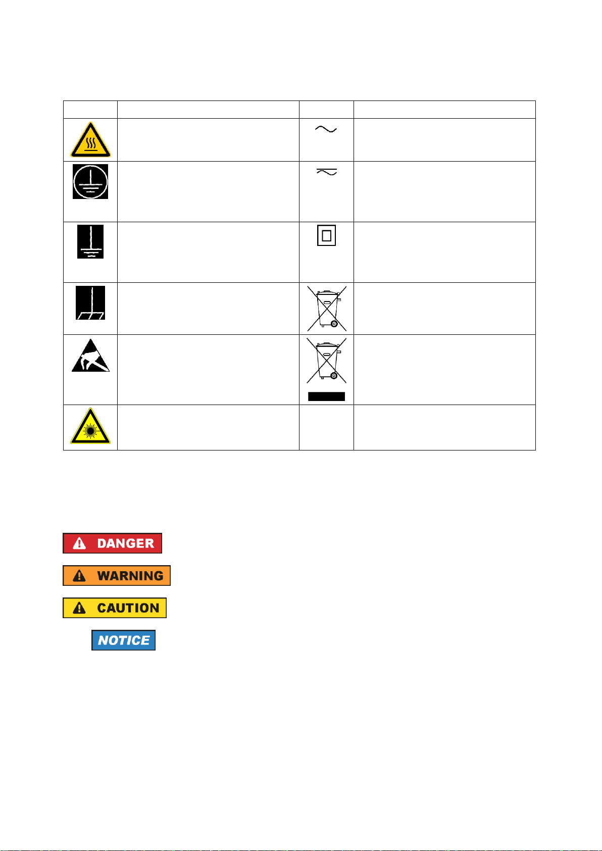
Symbol
Meaning
Symbol
Meaning
Caution ! Hot surface
Alternating current (AC)
Protective conductor terminal
To identify any terminal which is intended for
connection to an external conductor for
protection against electric shock in case of a
fault, or the terminal of a protective earth
Direct/alternating current (DC/AC)
Earth (Ground)
Class II Equipment
to identify equipment meeting the safety
requirements specified for Class II equipment
(device protected by double or reinforced
insulation)
Frame or chassis Ground terminal
EU labeling for batteries and accumulators
For additional information, see section "Waste
disposal/Environmental protection", item 1.
Be careful when handling electrostatic sensitive
devices
EU labeling for separate collection of electrical
and electronic devices
For additional information, see section "Waste
disposal/Environmental protection", item 2.
Warning! Laser radiation
For additional information, see section
"Operation", item 7.
Indicates a hazardous situation which, if not avoided, will result in death or
serious injury.
Indicates a hazardous situation which, if not avoided, could result in death or
serious injury.
Indicates a hazardous situation which, if not avoided, could result in minor or
moderate injury.
Indicates information considered important, but not hazard-related, e.g.
messages relating to property damage.
In the product documentation, the word ATTENTION is used synonymously.
Signal words and their meaning
The following signal words are used in the product documentation in order to warn the reader about risks
and dangers.
These signal words are in accordance with the standard definition for civil applications in the European
Economic Area. Definitions that deviate from the standard definition may also exist in other economic
areas or military applications. It is therefore essential to make sure that the signal words described here
are always used only in connection with the related product documentation and the related product. The
use of signal words in connection with unrelated products or documentation can result in misinterpretation
and in personal injury or material damage.
1171.0000.42 - 08 Page 2

Basic Safety Instructions
Operating states and operating positions
The product may be operated only under the operating conditions and in the positions specified by the
manufacturer, without the product's ventilation being obstructed. If the manufacturer's specifications are
not observed, this can result in electric shock, fire and/or serious personal injury or death. Applicable local
or national safety regulations and rules for the prevention of accidents must be observed in all work
performed.
1. Unless otherwise specified, the following requirements apply to Rohde & Schwarz products:
predefined operating position is always with the housing floor facing down, IP protection 2X, use only
indoors, max. operating altitude 2000 m above sea level, max. transport altitude 4500 m above sea
level. A tolerance of ±10 % shall apply to the nominal voltage and ±5 % to the nominal frequency,
overvoltage category 2, pollution degree 2.
2. Do not place the product on surfaces, vehicles, cabinets or tables that for reasons of weight or stability
are unsuitable for this purpose. Always follow the manufacturer's installation instructions when
installing the product and fastening it to objects or structures (e.g. walls and shelves). An installation
that is not carried out as described in the product documentation could result in personal injury or
even death.
3. Do not place the product on heat-generating devices such as radiators or fan heaters. The ambient
temperature must not exceed the maximum temperature specified in the product documentation or in
the data sheet. Product overheating can cause electric shock, fire and/or serious personal injury or
even death.
Electrical safety
If the information on electrical safety is not observed either at all or to the extent necessary, electric shock,
fire and/or serious personal injury or death may occur.
1. Prior to switching on the product, always ensure that the nominal voltage setting on the product
matches the nominal voltage of the mains-supply network. If a different voltage is to be set, the power
fuse of the product may have to be changed accordingly.
2. In the case of products of safety class I with movable power cord and connector, operation is
permitted only on sockets with a protective conductor contact and protective conductor.
3. Intentionally breaking the protective conductor either in the feed line or in the product itself is not
permitted. Doing so can result in the danger of an electric shock from the product. If extension cords
or connector strips are implemented, they must be checked on a regular basis to ensure that they are
safe to use.
4. If there is no power switch for disconnecting the product from the mains, or if the power switch is not
suitable for this purpose, use the plug of the connecting cable to disconnect the product from the
mains. In such cases, always ensure that the power plug is easily reachable and accessible at all
times. For example, if the power plug is the disconnecting device, the length of the connecting cable
must not exceed 3 m. Functional or electronic switches are not suitable for providing disconnection
from the AC supply network. If products without power switches are integrated into racks or systems,
the disconnecting device must be provided at the system level.
5. Never use the product if the power cable is damaged. Check the power cables on a regular basis to
ensure that they are in proper operating condition. By taking appropriate safety measures and
carefully laying the power cable, ensure that the cable cannot be damaged and that no one can be
hurt by, for example, tripping over the cable or suffering an electric shock.
1171.0000.42 - 08 Page 3

Basic Safety Instructions
6. The product may be operated only from TN/TT supply networks fuse-protected with max. 16 A (higher
fuse only after consulting with the Rohde & Schwarz group of companies).
7. Do not insert the plug into sockets that are dusty or dirty. Insert the plug firmly and all the way into the
socket provided for this purpose. Otherwise, sparks that result in fire and/or injuries may occur.
8. Do not overload any sockets, extension cords or connector strips; doing so can cause fire or electric
shocks.
9. For measurements in circuits with voltages V
> 30 V, suitable measures (e.g. appropriate
rms
measuring equipment, fuse protection, current limiting, electrical separation, insulation) should be
taken to avoid any hazards.
10. Ensure that the connections with information technology equipment, e.g. PCs or other industrial
computers, comply with the IEC 60950-1 / EN 60950-1 or IEC 61010-1 / EN 61010-1 standards that
apply in each case.
11. Unless expressly permitted, never remove the cover or any part of the housing while the product is in
operation. Doing so will expose circuits and components and can lead to injuries, fire or damage to the
product.
12. If a product is to be permanently installed, the connection between the protective conductor terminal
on site and the product's protective conductor must be made first before any other connection is
made. The product may be installed and connected only by a licensed electrician.
13. For permanently installed equipment without built-in fuses, circuit breakers or similar protective
devices, the supply circuit must be fuse-protected in such a way that anyone who has access to the
product, as well as the product itself, is adequately protected from injury or damage.
14. Use suitable overvoltage protection to ensure that no overvoltage (such as that caused by a bolt of
lightning) can reach the product. Otherwise, the person operating the product will be exposed to the
danger of an electric shock.
15. Any object that is not designed to be placed in the openings of the housing must not be used for this
purpose. Doing so can cause short circuits inside the product and/or electric shocks, fire or injuries.
16. Unless specified otherwise, products are not liquid-proof (see also section "Operating states and
operating positions", item 1). Therefore, the equipment must be protected against penetration by
liquids. If the necessary precautions are not taken, the user may suffer electric shock or the product
itself may be damaged, which can also lead to personal injury.
17. Never use the product under conditions in which condensation has formed or can form in or on the
product, e.g. if the product has been moved from a cold to a warm environment. Penetration by water
increases the risk of electric shock.
18. Prior to cleaning the product, disconnect it completely from the power supply (e.g. AC supply network
or battery). Use a soft, non-linting cloth to clean the product. Never use chemical cleaning agents such
as alcohol, acetone or diluents for cellulose lacquers.
Operation
1. Operating the products requires special training and intense concentration. Make sure that persons
who use the products are physically, mentally and emotionally fit enough to do so; otherwise, injuries
or material damage may occur. It is the responsibility of the employer/operator to select suitable
personnel for operating the products.
1171.0000.42 - 08 Page 4

Basic Safety Instructions
2. Before you move or transport the product, read and observe the section titled "Transport".
3. As with all industrially manufactured goods, the use of substances that induce an allergic reaction
(allergens) such as nickel cannot be generally excluded. If you develop an allergic reaction (such as a
skin rash, frequent sneezing, red eyes or respiratory difficulties) when using a Rohde & Schwarz
product, consult a physician immediately to determine the cause and to prevent health problems or
stress.
4. Before you start processing the product mechanically and/or thermally, or before you take it apart, be
sure to read and pay special attention to the section titled "Waste disposal/Environmental protection",
item 1.
5. Depending on the function, certain products such as RF radio equipment can produce an elevated
level of electromagnetic radiation. Considering that unborn babies require increased protection,
pregnant women must be protected by appropriate measures. Persons with pacemakers may also be
exposed to risks from electromagnetic radiation. The employer/operator must evaluate workplaces
where there is a special risk of exposure to radiation and, if necessary, take measures to avert the
potential danger.
6. Should a fire occur, the product may release hazardous substances (gases, fluids, etc.) that can
cause health problems. Therefore, suitable measures must be taken, e.g. protective masks and
protective clothing must be worn.
7. Laser products are given warning labels that are standardized according to their laser class. Lasers
can cause biological harm due to the properties of their radiation and due to their extremely
concentrated electromagnetic power. If a laser product (e.g. a CD/DVD drive) is integrated into a
Rohde & Schwarz product, absolutely no other settings or functions may be used as described in the
product documentation. The objective is to prevent personal injury (e.g. due to laser beams).
8. EMC classes (in line with EN 55011/CISPR 11, and analogously with EN 55022/CISPR 22,
EN 55032/CISPR 32)
Class A equipment:
Equipment suitable for use in all environments except residential environments and environments
that are directly connected to a low-voltage supply network that supplies residential buildings
Note: Class A equipment is intended for use in an industrial environment. This equipment may
cause radio disturbances in residential environments, due to possible conducted as well as
radiated disturbances. In this case, the operator may be required to take appropriate measures to
eliminate these disturbances.
Class B equipment:
Equipment suitable for use in residential environments and environments that are directly
connected to a low-voltage supply network that supplies residential buildings
Repair and service
1. The product may be opened only by authorized, specially trained personnel. Before any work is
performed on the product or before the product is opened, it must be disconnected from the AC supply
network. Otherwise, personnel will be exposed to the risk of an electric shock.
1171.0000.42 - 08 Page 5

Basic Safety Instructions
2. Adjustments, replacement of parts, maintenance and repair may be performed only by electrical
experts authorized by Rohde & Schwarz. Only original parts may be used for replacing parts relevant
to safety (e.g. power switches, power transformers, fuses). A safety test must always be performed
after parts relevant to safety have been replaced (visual inspection, protective conductor test,
insulation resistance measurement, leakage current measurement, functional test). This helps ensure
the continued safety of the product.
Batteries and rechargeable batteries/cells
If the information regarding batteries and rechargeable batteries/cells is not observed either at all or to the
extent necessary, product users may be exposed to the risk of explosions, fire and/or serious personal
injury, and, in some cases, death. Batteries and rechargeable batteries with alkaline electrolytes (e.g.
lithium cells) must be handled in accordance with the EN 62133 standard.
1. Cells must not be taken apart or crushed.
2. Cells or batteries must not be exposed to heat or fire. Storage in direct sunlight must be avoided.
Keep cells and batteries clean and dry. Clean soiled connectors using a dry, clean cloth.
3. Cells or batteries must not be short-circuited. Cells or batteries must not be stored in a box or in a
drawer where they can short-circuit each other, or where they can be short-circuited by other
conductive materials. Cells and batteries must not be removed from their original packaging until they
are ready to be used.
4. Cells and batteries must not be exposed to any mechanical shocks that are stronger than permitted.
5. If a cell develops a leak, the fluid must not be allowed to come into contact with the skin or eyes. If
contact occurs, wash the affected area with plenty of water and seek medical aid.
6. Improperly replacing or charging cells or batteries that contain alkaline electrolytes (e.g. lithium cells)
can cause explosions. Replace cells or batteries only with the matching Rohde & Schwarz type (see
parts list) in order to ensure the safety of the product.
7. Cells and batteries must be recycled and kept separate from residual waste. Rechargeable batteries
and normal batteries that contain lead, mercury or cadmium are hazardous waste. Observe the
national regulations regarding waste disposal and recycling.
Transport
1. The product may be very heavy. Therefore, the product must be handled with care. In some cases,
the user may require a suitable means of lifting or moving the product (e.g. with a lift-truck) to avoid
back or other physical injuries.
2. Handles on the products are designed exclusively to enable personnel to transport the product. It is
therefore not permissible to use handles to fasten the product to or on transport equipment such as
cranes, fork lifts, wagons, etc. The user is responsible for securely fastening the products to or on the
means of transport or lifting. Observe the safety regulations of the manufacturer of the means of
transport or lifting. Noncompliance can result in personal injury or material damage.
3. If you use the product in a vehicle, it is the sole responsibility of the driver to drive the vehicle safely
and properly. The manufacturer assumes no responsibility for accidents or collisions. Never use the
product in a moving vehicle if doing so could distract the driver of the vehicle. Adequately secure the
product in the vehicle to prevent injuries or other damage in the event of an accident.
1171.0000.42 - 08 Page 6

Instrucciones de seguridad elementales
Waste disposal/Environmental protection
1. Specially marked equipment has a battery or accumulator that must not be disposed of with unsorted
municipal waste, but must be collected separately. It may only be disposed of at a suitable collection
point or via a Rohde & Schwarz customer service center.
2. Waste electrical and electronic equipment must not be disposed of with unsorted municipal waste, but
must be collected separately.
Rohde & Schwarz GmbH & Co. KG has developed a disposal concept and takes full responsibility for
take-back obligations and disposal obligations for manufacturers within the EU. Contact your
Rohde & Schwarz customer service center for environmentally responsible disposal of the product.
3. If products or their components are mechanically and/or thermally processed in a manner that goes
beyond their intended use, hazardous substances (heavy-metal dust such as lead, beryllium, nickel)
may be released. For this reason, the product may only be disassembled by specially trained
personnel. Improper disassembly may be hazardous to your health. National waste disposal
regulations must be observed.
4. If handling the product releases hazardous substances or fuels that must be disposed of in a special
way, e.g. coolants or engine oils that must be replenished regularly, the safety instructions of the
manufacturer of the hazardous substances or fuels and the applicable regional waste disposal
regulations must be observed. Also observe the relevant safety instructions in the product
documentation. The improper disposal of hazardous substances or fuels can cause health problems
and lead to environmental damage.
For additional information about environmental protection, visit the Rohde & Schwarz website.
Instrucciones de seguridad elementales
¡Es imprescindible leer y cumplir las siguientes instrucciones e informaciones de seguridad!
El principio del grupo de empresas Rohde & Schwarz consiste en tener nuestros productos siempre al día
con los estándares de seguridad y de ofrecer a nuestros clientes el máximo grado de seguridad. Nuestros
productos y todos los equipos adicionales son siempre fabricados y examinados según las normas de
seguridad vigentes. Nuestro sistema de garantía de calidad controla constantemente que sean cumplidas
estas normas. El presente producto ha sido fabricado y examinado según el certificado de conformidad
de la UE y ha salido de nuestra planta en estado impecable según los estándares técnicos de seguridad.
Para poder preservar este estado y garantizar un funcionamiento libre de peligros, el usuario deberá
atenerse a todas las indicaciones, informaciones de seguridad y notas de alerta. El grupo de empresas
Rohde & Schwarz está siempre a su disposición en caso de que tengan preguntas referentes a estas
informaciones de seguridad.
Además queda en la responsabilidad del usuario utilizar el producto en la forma debida. Este producto
está destinado exclusivamente al uso en la industria y el laboratorio o, si ha sido expresamente
autorizado, para aplicaciones de campo y de ninguna manera deberá ser utilizado de modo que alguna
persona/cosa pueda sufrir daño. El uso del producto fuera de sus fines definidos o sin tener en cuenta las
instrucciones del fabricante queda en la responsabilidad del usuario. El fabricante no se hace en ninguna
forma responsable de consecuencias a causa del mal uso del producto.
1171.0000.42 - 08 Page 7
Instrucciones de seguridad elementales
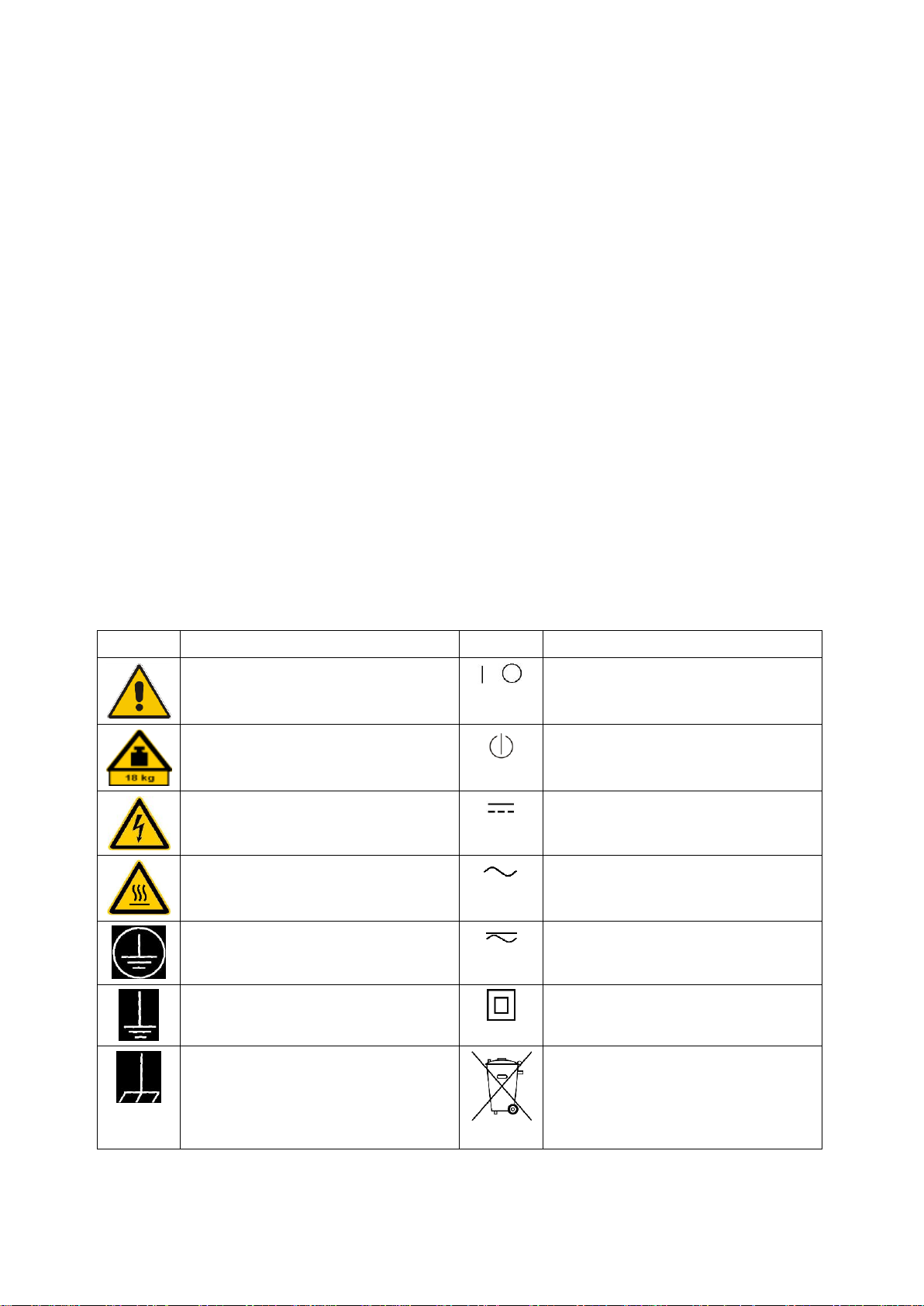
Símbolo
Significado
Símbolo
Significado
Aviso: punto de peligro general
Observar la documentación del producto
Tensión de alimentación de PUESTA EN
MARCHA / PARADA
Atención en el manejo de dispositivos de peso
elevado
Indicación de estado de espera (standby)
Peligro de choque eléctrico
Corriente continua (DC)
Advertencia: superficie caliente
Corriente alterna (AC)
Conexión a conductor de protección
Corriente continua / Corriente alterna (DC/AC)
Conexión a tierra
El aparato está protegido en su totalidad por un
aislamiento doble (reforzado)
Conexión a masa
Distintivo de la UE para baterías y
acumuladores
Más información en la sección
"Eliminación/protección del medio ambiente",
punto 1.
Se parte del uso correcto del producto para los fines definidos si el producto es utilizado conforme a las
indicaciones de la correspondiente documentación del producto y dentro del margen de rendimiento
definido (ver hoja de datos, documentación, informaciones de seguridad que siguen). El uso del producto
hace necesarios conocimientos técnicos y ciertos conocimientos del idioma inglés. Por eso se debe tener
en cuenta que el producto solo pueda ser operado por personal especializado o personas instruidas en
profundidad con las capacidades correspondientes. Si fuera necesaria indumentaria de seguridad para el
uso de productos de Rohde & Schwarz, encontraría la información debida en la documentación del
producto en el capítulo correspondiente. Guarde bien las informaciones de seguridad elementales, así
como la documentación del producto, y entréguelas a usuarios posteriores.
Tener en cuenta las informaciones de seguridad sirve para evitar en lo posible lesiones o daños por
peligros de toda clase. Por eso es imprescindible leer detalladamente y comprender por completo las
siguientes informaciones de seguridad antes de usar el producto, y respetarlas durante el uso del
producto. Deberán tenerse en cuenta todas las demás informaciones de seguridad, como p. ej. las
referentes a la protección de personas, que encontrarán en el capítulo correspondiente de la
documentación del producto y que también son de obligado cumplimiento. En las presentes
informaciones de seguridad se recogen todos los objetos que distribuye el grupo de empresas
Rohde & Schwarz bajo la denominación de "producto", entre ellos también aparatos, instalaciones así
como toda clase de accesorios. Los datos específicos del producto figuran en la hoja de datos y en la
documentación del producto.
Señalización de seguridad de los productos
Las siguientes señales de seguridad se utilizan en los productos para advertir sobre riesgos y peligros.
1171.0000.42 - 08 Page 8
Instrucciones de seguridad elementales
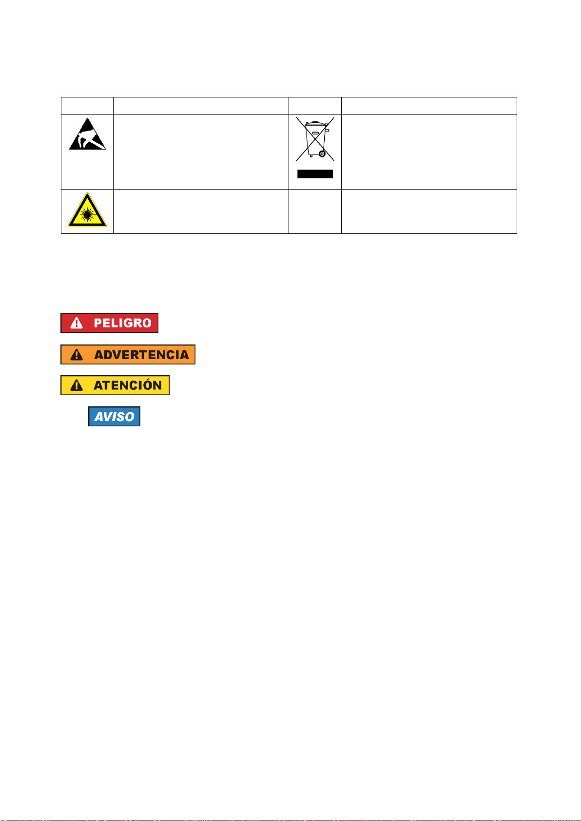
Símbolo
Significado
Símbolo
Significado
Aviso: Cuidado en el manejo de dispositivos
sensibles a la electrostática (ESD)
Distintivo de la UE para la eliminación por
separado de dispositivos eléctricos y
electrónicos
Más información en la sección
"Eliminación/protección del medio ambiente",
punto 2.
Advertencia: rayo láser
Más información en la sección
"Funcionamiento", punto 7.
Indica una situación de peligro que, si no se evita, causa lesiones
graves o incluso la muerte.
Indica una situación de peligro que, si no se evita, puede causar
lesiones graves o incluso la muerte.
Indica una situación de peligro que, si no se evita, puede causar
lesiones leves o moderadas.
Indica información que se considera importante, pero no en relación
con situaciones de peligro; p. ej., avisos sobre posibles daños
materiales.
En la documentación del producto se emplea de forma sinónima el
término CUIDADO.
Palabras de señal y su significado
En la documentación del producto se utilizan las siguientes palabras de señal con el fin de advertir contra
riesgos y peligros.
Las palabras de señal corresponden a la definición habitual para aplicaciones civiles en el área
económica europea. Pueden existir definiciones diferentes a esta definición en otras áreas económicas o
en aplicaciones militares. Por eso se deberá tener en cuenta que las palabras de señal aquí descritas
sean utilizadas siempre solamente en combinación con la correspondiente documentación del producto y
solamente en combinación con el producto correspondiente. La utilización de las palabras de señal en
combinación con productos o documentaciones que no les correspondan puede llevar a interpretaciones
equivocadas y tener por consecuencia daños en personas u objetos.
Estados operativos y posiciones de funcionamiento
El producto solamente debe ser utilizado según lo indicado por el fabricante respecto a los estados
operativos y posiciones de funcionamiento sin que se obstruya la ventilación. Si no se siguen las
indicaciones del fabricante, pueden producirse choques eléctricos, incendios y/o lesiones graves con
posible consecuencia de muerte. En todos los trabajos deberán ser tenidas en cuenta las normas
nacionales y locales de seguridad del trabajo y de prevención de accidentes.
1171.0000.42 - 08 Page 9

Instrucciones de seguridad elementales
1. Si no se convino de otra manera, es para los productos Rohde & Schwarz válido lo que sigue:
como posición de funcionamiento se define por principio la posición con el suelo de la caja para
abajo, modo de protección IP 2X, uso solamente en estancias interiores, utilización hasta 2000 m
sobre el nivel del mar, transporte hasta 4500 m sobre el nivel del mar. Se aplicará una tolerancia de
±10 % sobre el voltaje nominal y de ±5 % sobre la frecuencia nominal. Categoría de sobrecarga
eléctrica 2, índice de suciedad 2.
2. No sitúe el producto encima de superficies, vehículos, estantes o mesas, que por sus características
de peso o de estabilidad no sean aptos para él. Siga siempre las instrucciones de instalación del
fabricante cuando instale y asegure el producto en objetos o estructuras (p. ej. paredes y estantes). Si
se realiza la instalación de modo distinto al indicado en la documentación del producto, se pueden
causar lesiones o, en determinadas circunstancias, incluso la muerte.
3. No ponga el producto sobre aparatos que generen calor (p. ej. radiadores o calefactores). La
temperatura ambiente no debe superar la temperatura máxima especificada en la documentación del
producto o en la hoja de datos. En caso de sobrecalentamiento del producto, pueden producirse
choques eléctricos, incendios y/o lesiones graves con posible consecuencia de muerte.
Seguridad eléctrica
Si no se siguen (o se siguen de modo insuficiente) las indicaciones del fabricante en cuanto a seguridad
eléctrica, pueden producirse choques eléctricos, incendios y/o lesiones graves con posible consecuencia
de muerte.
1. Antes de la puesta en marcha del producto se deberá comprobar siempre que la tensión
preseleccionada en el producto coincida con la de la red de alimentación eléctrica. Si es necesario
modificar el ajuste de tensión, también se deberán cambiar en caso dado los fusibles
correspondientes del producto.
2. Los productos de la clase de protección I con alimentación móvil y enchufe individual solamente
podrán enchufarse a tomas de corriente con contacto de seguridad y con conductor de protección
conectado.
3. Queda prohibida la interrupción intencionada del conductor de protección, tanto en la toma de
corriente como en el mismo producto. La interrupción puede tener como consecuencia el riesgo de
que el producto sea fuente de choques eléctricos. Si se utilizan cables alargadores o regletas de
enchufe, deberá garantizarse la realización de un examen regular de los mismos en cuanto a su
estado técnico de seguridad.
4. Si el producto no está equipado con un interruptor para desconectarlo de la red, o bien si el
interruptor existente no resulta apropiado para la desconexión de la red, el enchufe del cable de
conexión se deberá considerar como un dispositivo de desconexión.
El dispositivo de desconexión se debe poder alcanzar fácilmente y debe estar siempre bien accesible.
Si, p. ej., el enchufe de conexión a la red es el dispositivo de desconexión, la longitud del cable de
conexión no debe superar 3 m).
Los interruptores selectores o electrónicos no son aptos para el corte de la red eléctrica. Si se
integran productos sin interruptor en bastidores o instalaciones, se deberá colocar el interruptor en el
nivel de la instalación.
5. No utilice nunca el producto si está dañado el cable de conexión a red. Compruebe regularmente el
correcto estado de los cables de conexión a red. Asegúrese, mediante las medidas de protección y
de instalación adecuadas, de que el cable de conexión a red no pueda ser dañado o de que nadie
pueda ser dañado por él, p. ej. al tropezar o por un choque eléctrico.
1171.0000.42 - 08 Page 10

Instrucciones de seguridad elementales
6. Solamente está permitido el funcionamiento en redes de alimentación TN/TT aseguradas con fusibles
de 16 A como máximo (utilización de fusibles de mayor amperaje solo previa consulta con el grupo de
empresas Rohde & Schwarz).
7. Nunca conecte el enchufe en tomas de corriente sucias o llenas de polvo. Introduzca el enchufe por
completo y fuertemente en la toma de corriente. La no observación de estas medidas puede provocar
chispas, fuego y/o lesiones.
8. No sobrecargue las tomas de corriente, los cables alargadores o las regletas de enchufe ya que esto
podría causar fuego o choques eléctricos.
9. En las mediciones en circuitos de corriente con una tensión U
> 30 V se deberán tomar las medidas
eff
apropiadas para impedir cualquier peligro (p. ej. medios de medición adecuados, seguros, limitación
de tensión, corte protector, aislamiento etc.).
10. Para la conexión con dispositivos informáticos como un PC o un ordenador industrial, debe
comprobarse que éstos cumplan los estándares IEC60950-1/EN60950-1 o IEC61010-1/EN 61010-1
válidos en cada caso.
11. A menos que esté permitido expresamente, no retire nunca la tapa ni componentes de la carcasa
mientras el producto esté en servicio. Esto pone a descubierto los cables y componentes eléctricos y
puede causar lesiones, fuego o daños en el producto.
12. Si un producto se instala en un lugar fijo, se deberá primero conectar el conductor de protección fijo
con el conductor de protección del producto antes de hacer cualquier otra conexión. La instalación y
la conexión deberán ser efectuadas por un electricista especializado.
13. En el caso de dispositivos fijos que no estén provistos de fusibles, interruptor automático ni otros
mecanismos de seguridad similares, el circuito de alimentación debe estar protegido de modo que
todas las personas que puedan acceder al producto, así como el producto mismo, estén a salvo de
posibles daños.
14. Todo producto debe estar protegido contra sobretensión (debida p. ej. a una caída del rayo) mediante
los correspondientes sistemas de protección. Si no, el personal que lo utilice quedará expuesto al
peligro de choque eléctrico.
15. No debe introducirse en los orificios de la caja del aparato ningún objeto que no esté destinado a ello.
Esto puede producir cortocircuitos en el producto y/o puede causar choques eléctricos, fuego o
lesiones.
16. Salvo indicación contraria, los productos no están impermeabilizados (ver también el capítulo
"Estados operativos y posiciones de funcionamiento", punto 1). Por eso es necesario tomar las
medidas necesarias para evitar la entrada de líquidos. En caso contrario, existe peligro de choque
eléctrico para el usuario o de daños en el producto, que también pueden redundar en peligro para las
personas.
17. No utilice el producto en condiciones en las que pueda producirse o ya se hayan producido
condensaciones sobre el producto o en el interior de éste, como p. ej. al desplazarlo de un lugar frío a
otro caliente. La entrada de agua aumenta el riesgo de choque eléctrico.
18. Antes de la limpieza, desconecte por completo el producto de la alimentación de tensión (p. ej. red de
alimentación o batería). Realice la limpieza de los aparatos con un paño suave, que no se deshilache.
No utilice bajo ningún concepto productos de limpieza químicos como alcohol, acetona o diluyentes
para lacas nitrocelulósicas.
1171.0000.42 - 08 Page 11

Instrucciones de seguridad elementales
Funcionamiento
1. El uso del producto requiere instrucciones especiales y una alta concentración durante el manejo.
Debe asegurarse que las personas que manejen el producto estén a la altura de los requerimientos
necesarios en cuanto a aptitudes físicas, psíquicas y emocionales, ya que de otra manera no se
pueden excluir lesiones o daños de objetos. El empresario u operador es responsable de seleccionar
el personal usuario apto para el manejo del producto.
2. Antes de desplazar o transportar el producto, lea y tenga en cuenta el capítulo "Transporte".
3. Como con todo producto de fabricación industrial no puede quedar excluida en general la posibilidad
de que se produzcan alergias provocadas por algunos materiales empleados ―los llamados
alérgenos (p. ej. el níquel)―. Si durante el manejo de productos Rohde & Schwarz se producen
reacciones alérgicas, como p. ej. irritaciones cutáneas, estornudos continuos, enrojecimiento de la
conjuntiva o dificultades respiratorias, debe avisarse inmediatamente a un médico para investigar las
causas y evitar cualquier molestia o daño a la salud.
4. Antes de la manipulación mecánica y/o térmica o el desmontaje del producto, debe tenerse en cuenta
imprescindiblemente el capítulo "Eliminación/protección del medio ambiente", punto 1.
5. Ciertos productos, como p. ej. las instalaciones de radiocomunicación RF, pueden a causa de su
función natural, emitir una radiación electromagnética aumentada. Deben tomarse todas las medidas
necesarias para la protección de las mujeres embarazadas. También las personas con marcapasos
pueden correr peligro a causa de la radiación electromagnética. El empresario/operador tiene la
obligación de evaluar y señalizar las áreas de trabajo en las que exista un riesgo elevado de
exposición a radiaciones.
6. Tenga en cuenta que en caso de incendio pueden desprenderse del producto sustancias tóxicas
(gases, líquidos etc.) que pueden generar daños a la salud. Por eso, en caso de incendio deben
usarse medidas adecuadas, como p. ej. máscaras antigás e indumentaria de protección.
7. Los productos con láser están provistos de indicaciones de advertencia normalizadas en función de la
clase de láser del que se trate. Los rayos láser pueden provocar daños de tipo biológico a causa de
las propiedades de su radiación y debido a su concentración extrema de potencia electromagnética.
En caso de que un producto Rohde & Schwarz contenga un producto láser (p. ej. un lector de
CD/DVD), no debe usarse ninguna otra configuración o función aparte de las descritas en la
documentación del producto, a fin de evitar lesiones (p. ej. debidas a irradiación láser).
8. Clases de compatibilidad electromagnética (conforme a EN 55011 / CISPR 11; y en analogía con EN
55022 / CISPR 22, EN 55032 / CISPR 32)
Aparato de clase A:
Aparato adecuado para su uso en todos los entornos excepto en los residenciales y en aquellos
conectados directamente a una red de distribución de baja tensión que suministra corriente a
edificios residenciales.
Nota: Los aparatos de clase A están destinados al uso en entornos industriales. Estos aparatos
pueden causar perturbaciones radioeléctricas en entornos residenciales debido a posibles
perturbaciones guiadas o radiadas. En este caso, se le podrá solicitar al operador que tome las
medidas adecuadas para eliminar estas perturbaciones.
Aparato de clase B:
Aparato adecuado para su uso en entornos residenciales, así como en aquellos conectados
directamente a una red de distribución de baja tensión que suministra corriente a edificios
residenciales.
1171.0000.42 - 08 Page 12

Instrucciones de seguridad elementales
Reparación y mantenimiento
1. El producto solamente debe ser abierto por personal especializado con autorización para ello. Antes
de manipular el producto o abrirlo, es obligatorio desconectarlo de la tensión de alimentación, para
evitar toda posibilidad de choque eléctrico.
2. El ajuste, el cambio de partes, el mantenimiento y la reparación deberán ser efectuadas solamente
por electricistas autorizados por Rohde & Schwarz. Si se reponen partes con importancia para los
aspectos de seguridad (p. ej. el enchufe, los transformadores o los fusibles), solamente podrán ser
sustituidos por partes originales. Después de cada cambio de partes relevantes para la seguridad
deberá realizarse un control de seguridad (control a primera vista, control del conductor de
protección, medición de resistencia de aislamiento, medición de la corriente de fuga, control de
funcionamiento). Con esto queda garantizada la seguridad del producto.
Baterías y acumuladores o celdas
Si no se siguen (o se siguen de modo insuficiente) las indicaciones en cuanto a las baterías y
acumuladores o celdas, pueden producirse explosiones, incendios y/o lesiones graves con posible
consecuencia de muerte. El manejo de baterías y acumuladores con electrolitos alcalinos (p. ej. celdas de
litio) debe seguir el estándar EN 62133.
1. No deben desmontarse, abrirse ni triturarse las celdas.
2. Las celdas o baterías no deben someterse a calor ni fuego. Debe evitarse el almacenamiento a la luz
directa del sol. Las celdas y baterías deben mantenerse limpias y secas. Limpiar las conexiones
sucias con un paño seco y limpio.
3. Las celdas o baterías no deben cortocircuitarse. Es peligroso almacenar las celdas o baterías en
estuches o cajones en cuyo interior puedan cortocircuitarse por contacto recíproco o por contacto con
otros materiales conductores. No deben extraerse las celdas o baterías de sus embalajes originales
hasta el momento en que vayan a utilizarse.
4. Las celdas o baterías no deben someterse a impactos mecánicos fuertes indebidos.
5. En caso de falta de estanqueidad de una celda, el líquido vertido no debe entrar en contacto con la
piel ni los ojos. Si se produce contacto, lavar con agua abundante la zona afectada y avisar a un
médico.
6. En caso de cambio o recarga inadecuados, las celdas o baterías que contienen electrolitos alcalinos
(p. ej. las celdas de litio) pueden explotar. Para garantizar la seguridad del producto, las celdas o
baterías solo deben ser sustituidas por el tipo Rohde & Schwarz correspondiente (ver lista de
recambios).
7. Las baterías y celdas deben reciclarse y no deben tirarse a la basura doméstica. Las baterías o
acumuladores que contienen plomo, mercurio o cadmio deben tratarse como residuos especiales.
Respete en esta relación las normas nacionales de eliminación y reciclaje.
Transporte
1. El producto puede tener un peso elevado. Por eso es necesario desplazarlo o transportarlo con
precaución y, si es necesario, usando un sistema de elevación adecuado (p. ej. una carretilla
elevadora), a fin de evitar lesiones en la espalda u otros daños personales.
1171.0000.42 - 08 Page 13

Instrucciones de seguridad elementales
2. Las asas instaladas en los productos sirven solamente de ayuda para el transporte del producto por
personas. Por eso no está permitido utilizar las asas para la sujeción en o sobre medios de transporte
como p. ej. grúas, carretillas elevadoras de horquilla, carros etc. Es responsabilidad suya fijar los
productos de manera segura a los medios de transporte o elevación. Para evitar daños personales o
daños en el producto, siga las instrucciones de seguridad del fabricante del medio de transporte o
elevación utilizado.
3. Si se utiliza el producto dentro de un vehículo, recae de manera exclusiva en el conductor la
responsabilidad de conducir el vehículo de manera segura y adecuada. El fabricante no asumirá
ninguna responsabilidad por accidentes o colisiones. No utilice nunca el producto dentro de un
vehículo en movimiento si esto pudiera distraer al conductor. Asegure el producto dentro del vehículo
debidamente para evitar, en caso de un accidente, lesiones u otra clase de daños.
Eliminación/protección del medio ambiente
1. Los dispositivos marcados contienen una batería o un acumulador que no se debe desechar con los
residuos domésticos sin clasificar, sino que debe ser recogido por separado. La eliminación se debe
efectuar exclusivamente a través de un punto de recogida apropiado o del servicio de atención al
cliente de Rohde & Schwarz.
2. Los dispositivos eléctricos usados no se deben desechar con los residuos domésticos sin clasificar,
sino que deben ser recogidos por separado.
Rohde & Schwarz GmbH & Co.KG ha elaborado un concepto de eliminación de residuos y asume
plenamente los deberes de recogida y eliminación para los fabricantes dentro de la UE. Para
desechar el producto de manera respetuosa con el medio ambiente, diríjase a su servicio de atención
al cliente de Rohde & Schwarz.
3. Si se trabaja de manera mecánica y/o térmica cualquier producto o componente más allá del
funcionamiento previsto, pueden liberarse sustancias peligrosas (polvos con contenido de metales
pesados como p. ej. plomo, berilio o níquel). Por eso el producto solo debe ser desmontado por
personal especializado con formación adecuada. Un desmontaje inadecuado puede ocasionar daños
para la salud. Se deben tener en cuenta las directivas nacionales referentes a la eliminación de
residuos.
4. En caso de que durante el trato del producto se formen sustancias peligrosas o combustibles que
deban tratarse como residuos especiales (p. ej. refrigerantes o aceites de motor con intervalos de
cambio definidos), deben tenerse en cuenta las indicaciones de seguridad del fabricante de dichas
sustancias y las normas regionales de eliminación de residuos. Tenga en cuenta también en caso
necesario las indicaciones de seguridad especiales contenidas en la documentación del producto. La
eliminación incorrecta de sustancias peligrosas o combustibles puede causar daños a la salud o
daños al medio ambiente.
Se puede encontrar más información sobre la protección del medio ambiente en la página web de
Rohde & Schwarz.
1171.0000.42 - 08 Page 14

Quality management
Certied Quality System
ISO 9001
and environmental
management
Sehr geehrter Kunde,
Sie haben sich für den Kauf
eines Rohde & Schwarz Produktes entschieden. Sie erhalten
damit ein nach modernsten Fertigungsmethoden hergestelltes
Produkt. Es wurde nach den
Regeln unserer Qualitäts- und
Umweltmanagementsysteme
entwickelt, gefertigt und geprüft.
Rohde & Schwarz ist unter anderem nach den Managementsystemen ISO 9001 und ISO 14001
zertifiziert.
Der Umwelt verpflichtet
❙ Energie-efziente,
RoHS-konforme Produkte
❙ Kontinuierliche
Weiterentwicklung nachhaltiger
Umweltkonzepte
❙ ISO 14001-zertiziertes
Umweltmanagementsystem
Dear customer,
You have decided to buy a
Rohde & Schwarz product. This
product has been manufactured
using the most advanced methods. It was developed, manufactured and tested in compliance
with our quality management
and environmental management systems. Rohde & Schwarz
has been certified, for example, according to the ISO 9001
and ISO 14001 management
systems.
Environmental commitment
❙ Energy-efcient products
❙ Continuous improvement in
environmental sustainability
❙ ISO 14001-certied
environmental management
system
Certied Environmental System
ISO 14001
Cher client,
Vous avez choisi d’acheter un
produit Rohde & Schwarz. Vous
disposez donc d’un produit
fabriqué d’après les méthodes
les plus avancées. Le développement, la fabrication et les
tests de ce produit ont été effectués selon nos systèmes de
management de qualité et de
management environnemental.
La société Rohde & Schwarz a
été homologuée, entre autres,
conformément aux systèmes
de management ISO 9001 et
ISO 14001.
Engagement écologique
❙ Produits à efcience
énergétique
❙ Amélioration continue de la
durabilité environnementale
❙ Système de management
environnemental certié selon
ISO 14001
1171.0200.11 V 05.01
1171020011

Customer Support
Technical support – where and when you need it
For quick, expert help with any Rohde & Schwarz equipment, contact one of our Customer Support
Centers. A team of highly qualified engineers provides telephone support and will work with you to find a
solution to your query on any aspect of the operation, programming or applications of Rohde & Schwarz
equipment.
Up-to-date information and upgrades
To keep your instrument up-to-date and to be informed about new application notes related to your
instrument, please send an e-mail to the Customer Support Center stating your instrument and your wish.
We will take care that you will get the right information.
Europe, Africa, Middle East
North America
Latin America
Asia/Pacific
China
Phone +49 89 4129 12345
customersupport@rohde-schwarz.com
Phone 1-888-TEST-RSA (1-888-837-8772)
customer.support@rsa.rohde-schwarz.com
Phone +1-410-910-7988
customersupport.la@rohde-schwarz.com
Phone +65 65 13 04 88
customersupport.asia@rohde-schwarz.com
Phone +86-800-810-8228 /
+86-400-650-5896
customersupport.china@rohde-schwarz.com
1171.0200.22-06.00

R&S ESU Contents
Contents
1 Front and Rear Panel . . . . . . . . . . . . . . . . . . . . . . . . . . . . . . . . . 1.1
1.1 Front View . . . . . . . . . . . . . . . . . . . . . . . . . . . . . . . . . . . . . . . . . . . . . . . . . . . 1.2
1.2 Function Keys on the Front Panel . . . . . . . . . . . . . . . . . . . . . . . . . . . . . . . 1.4
1.3 Front Panel Connections . . . . . . . . . . . . . . . . . . . . . . . . . . . . . . . . . . . . . . 1.6
1.4 Rear View . . . . . . . . . . . . . . . . . . . . . . . . . . . . . . . . . . . . . . . . . . . . . . . . . . 1.10
1.5 Rear Panel Connections . . . . . . . . . . . . . . . . . . . . . . . . . . . . . . . . . . . . . . 1.12
2 Preparing for Use . . . . . . . . . . . . . . . . . . . . . . . . . . . . . . . . . . . . 2.1
2.1 Preparing for Operation . . . . . . . . . . . . . . . . . . . . . . . . . . . . . . . . . . . . . . . . 2.4
2.1.1 Unpacking the Instrument . . . . . . . . . . . . . . . . . . . . . . . . . . . . . . . . . . . 2.4
2.1.2 Setting Up the Instrument . . . . . . . . . . . . . . . . . . . . . . . . . . . . . . . . . . . . 2.5
2.1.3 Installation in a 19" Rack . . . . . . . . . . . . . . . . . . . . . . . . . . . . . . . . . . . . 2.6
2.1.4 Connecting the Instrument to the AC Power Supply . . . . . . . . . . . . . . . 2.6
2.1.5 Switching On the R&S FSP . . . . . . . . . . . . . . . . . . . . . . . . . . . . . . . . . . 2.6
2.1.6 Functional Test . . . . . . . . . . . . . . . . . . . . . . . . . . . . . . . . . . . . . . . . . . . . 2.7
2.1.7 Switching Off the R&S FSP . . . . . . . . . . . . . . . . . . . . . . . . . . . . . . . . . . 2.8
2.1.8 Cleaning the Outside . . . . . . . . . . . . . . . . . . . . . . . . . . . . . . . . . . . . . . . 2.8
2.2 Instrument Drive Usage . . . . . . . . . . . . . . . . . . . . . . . . . . . . . . . . . . . . . . . . 2.9
2.3 Connecting External Devices . . . . . . . . . . . . . . . . . . . . . . . . . . . . . . . . . . 2.10
2.3.1 Connecting an External Keyboard . . . . . . . . . . . . . . . . . . . . . . . . . . . . 2.10
2.3.2 Connecting a Mouse . . . . . . . . . . . . . . . . . . . . . . . . . . . . . . . . . . . . . . 2.14
2.3.3 Connecting an External Monitor . . . . . . . . . . . . . . . . . . . . . . . . . . . . . . 2.15
2.3.4 Connecting a Printer . . . . . . . . . . . . . . . . . . . . . . . . . . . . . . . . . . . . . . . 2.16
2.3.5 Connecting USB Devices (e.g. a Power Meter) . . . . . . . . . . . . . . . . . . 2.18
2.3.6 Connecting External Generators . . . . . . . . . . . . . . . . . . . . . . . . . . . . . 2.21
2.3.7 Connecting External Generators . . . . . . . . . . . . . . . . . . . . . . . . . . . . . . 2.21
2.3.7.1 Connecting the R&S FSP to the Generator . . . . . . . . . . . . . . . . . 2.24
2.3.7.2 Connecting the R&S FSP to the Generator . . . . . . . . . . . . . . . . . 2.24
2.3.7.3 Configuring the Generator on the R&S FSP . . . . . . . . . . . . . . . . 2.25
2.3.7.4 Configuring the Generator on the R&S FSP . . . . . . . . . . . . . . . . . 2.25
2.3.7.5 Activating the Generator Configuration and Setting the Output
Level . . . . . . . . . . . . . . . . . . . . . . . . . . . . . . . . . . . . . . . . . . . . . . . . . . . . . 2.27
2.3.7.6 Activating the Generator Configuration and Setting the Output
Level . . . . . . . . . . . . . . . . . . . . . . . . . . . . . . . . . . . . . . . . . . . . . . . . . . . . . 2.27
2.3.7.7 Using an External Generator as a Tracking Generator . . . . . . . . 2.29
2.3.7.8 Using an External Generator as a Tracking Generator . . . . . . . . . 2.29
2.4 Setup . . . . . . . . . . . . . . . . . . . . . . . . . . . . . . . . . . . . . . . . . . . . . . . . . . . . . . 2.31
2.4.1 Selecting the Frequency Reference . . . . . . . . . . . . . . . . . . . . . . . . . . . 2.31
Quick Start Guide 1302.6163.62 - 05 1

R&S ESU Contents
2.4.2 Setting the Date and Time . . . . . . . . . . . . . . . . . . . . . . . . . . . . . . . . . . . 2.31
2.4.3 Setting the GPIB Interface . . . . . . . . . . . . . . . . . . . . . . . . . . . . . . . . . . . 2.33
2.4.3.1 GPIB Address . . . . . . . . . . . . . . . . . . . . . . . . . . . . . . . . . . . . . . . . 2.33
2.4.3.2 GPIB Language . . . . . . . . . . . . . . . . . . . . . . . . . . . . . . . . . . . . . . . 2.33
2.4.3.3 GPIB Language . . . . . . . . . . . . . . . . . . . . . . . . . . . . . . . . . . . . . . . 2.34
2.4.3.4 ID Response String . . . . . . . . . . . . . . . . . . . . . . . . . . . . . . . . . . . . 2.38
2.4.4 Setting the Screen Colors . . . . . . . . . . . . . . . . . . . . . . . . . . . . . . . . . . . 2.39
2.4.5 Automatically Switching Off the Internal Screen . . . . . . . . . . . . . . . . . . 2.40
2.4.6 File and Path Selection Using the Front Panel Keys . . . . . . . . . . . . . . . 2.41
2.4.7 Selecting and Configuring Printers . . . . . . . . . . . . . . . . . . . . . . . . . . . . 2.43
2.4.7.1 Selecting Alternative Printer Configurations . . . . . . . . . . . . . . . . . 2.44
2.4.7.2 Selecting Printer Colors . . . . . . . . . . . . . . . . . . . . . . . . . . . . . . . . . 2.44
2.4.8 Installing Plug&Play Printers . . . . . . . . . . . . . . . . . . . . . . . . . . . . . . . . . 2.46
2.4.9 Installing Non-Plug&Play Printers . . . . . . . . . . . . . . . . . . . . . . . . . . . . . 2.47
2.5 Configuring the LAN Interface (Option R&S FSP-B16 only) . . . . . . . . . . 2.47
2.6 Configuring the LAN Interface (Option R&S FSP-B16 only) . . . . . . . . . . . 2.47
2.7 Configuring the LAN Interface . . . . . . . . . . . . . . . . . . . . . . . . . . . . . . . . . . 2.48
2.8 Configuring the LAN Interface . . . . . . . . . . . . . . . . . . . . . . . . . . . . . . . . . . 2.48
2.9 Configuring the LAN Interface . . . . . . . . . . . . . . . . . . . . . . . . . . . . . . . . . . 2.48
2.10 Configuring the LAN Interface . . . . . . . . . . . . . . . . . . . . . . . . . . . . . . . . . 2.49
2.10.1 Connecting the Instrument to the Network . . . . . . . . . . . . . . . . . . . . . 2.49
2.10.2 Configuring the Network Card . . . . . . . . . . . . . . . . . . . . . . . . . . . . . . . 2.50
2.10.2.1 Driver Installation . . . . . . . . . . . . . . . . . . . . . . . . . . . . . . . . . . . . . 2.50
2.10.2.2 Configuring the Interface . . . . . . . . . . . . . . . . . . . . . . . . . . . . . . . 2.50
2.10.2.3 Configuring Existing Network Protocols (TCP/IP Protocol) . . . . . 2.51
2.10.2.4 Installing Additional Network Protocols and Services . . . . . . . . . 2.57
2.10.3 Login . . . . . . . . . . . . . . . . . . . . . . . . . . . . . . . . . . . . . . . . . . . . . . . . . . 2.58
2.11 LXI Configuration . . . . . . . . . . . . . . . . . . . . . . . . . . . . . . . . . . . . . . . . . . . . 2.59
2.11.1 LXI Configuration Dialog . . . . . . . . . . . . . . . . . . . . . . . . . . . . . . . . . . . 2.60
2.11.2 LXI Browser Interface . . . . . . . . . . . . . . . . . . . . . . . . . . . . . . . . . . . . . 2.60
2.11.3 LAN Configuration website . . . . . . . . . . . . . . . . . . . . . . . . . . . . . . . . . 2.61
2.11.4 Ping . . . . . . . . . . . . . . . . . . . . . . . . . . . . . . . . . . . . . . . . . . . . . . . . . . . . 2.62
2.12 Operating System Properties . . . . . . . . . . . . . . . . . . . . . . . . . . . . . . . . . . 2.63
2.12.0.1 Windows Service Packs . . . . . . . . . . . . . . . . . . . . . . . . . . . . . . . 2.63
2.12.0.2 Opening the Windows Start Menu . . . . . . . . . . . . . . . . . . . . . . . . 2.64
2.12.0.3 Windows Software Approved for the Instrument . . . . . . . . . . . . . 2.65
3 Firmware Update and Installation of Firmware Options . . . . .3.1
3.1 Firmware Update . . . . . . . . . . . . . . . . . . . . . . . . . . . . . . . . . . . . . . . . . . . . . . 3.2
3.2 Activating Firmware Options . . . . . . . . . . . . . . . . . . . . . . . . . . . . . . . . . . . . 3.4
2 Quick Start Guide 1302.6163.62 - 05

R&S ESU Contents
4 Basic Operation . . . . . . . . . . . . . . . . . . . . . . . . . . . . . . . . . . . . . 4.1
4.1 Diagram Layout . . . . . . . . . . . . . . . . . . . . . . . . . . . . . . . . . . . . . . . . . . . . . . 4.2
4.1.1 Displays in the Diagram Area . . . . . . . . . . . . . . . . . . . . . . . . . . . . . . . . . 4.3
4.2 Setting Parameters . . . . . . . . . . . . . . . . . . . . . . . . . . . . . . . . . . . . . . . . . . . . 4.7
4.2.1 The Keypad . . . . . . . . . . . . . . . . . . . . . . . . . . . . . . . . . . . . . . . . . . . . . . 4.7
4.2.2 The Rotary Knob and Arrow Keys . . . . . . . . . . . . . . . . . . . . . . . . . . . . . 4.8
4.2.3 Editing Numeric Parameters . . . . . . . . . . . . . . . . . . . . . . . . . . . . . . . . . 4.8
4.2.4 Editing Alphanumeric Parameters . . . . . . . . . . . . . . . . . . . . . . . . . . . . . 4.9
4.2.4.1 Alphanumeric Editor Type 1: . . . . . . . . . . . . . . . . . . . . . . . . . . . . . 4.9
4.2.4.2 Alphanumeric Editor Type 2: . . . . . . . . . . . . . . . . . . . . . . . . . . . . 4.10
5 Basic Measurement Examples . . . . . . . . . . . . . . . . . . . . . . . . . 5.1
5.1 Introduction . . . . . . . . . . . . . . . . . . . . . . . . . . . . . . . . . . . . . . . . . . . . . . . . . . 5.3
5.2 Performing a Level and Frequency Measurement . . . . . . . . . . . . . . . . . . 5.4
5.3 Measuring a Sinusoidal Signal . . . . . . . . . . . . . . . . . . . . . . . . . . . . . . . . . 5.16
5.3.1 Measuring the Level and Frequency with Markers . . . . . . . . . . . . . . . . 5.16
5.3.1.1 Procedure . . . . . . . . . . . . . . . . . . . . . . . . . . . . . . . . . . . . . . . . . . . 5.16
5.3.1.2 Increasing the Frequency Resolution . . . . . . . . . . . . . . . . . . . . . . 5.17
5.3.1.3 Setting the Reference Level . . . . . . . . . . . . . . . . . . . . . . . . . . . . . 5.18
5.3.2 Measuring the Signal Frequency using the Frequency Counter . . . . . 5.19
5.4 Measuring Harmonics of Sinusoidal Signals . . . . . . . . . . . . . . . . . . . . . . 5.21
5.4.1 Measuring the Suppression of the First and Second Harmonic of
an Input Signal . . . . . . . . . . . . . . . . . . . . . . . . . . . . . . . . . . . . . . . . . . . . . . . . 5.21
5.4.2 Reducing Noise . . . . . . . . . . . . . . . . . . . . . . . . . . . . . . . . . . . . . . . . . . 5.23
5.5 Measuring Harmonics with Frequency Sweeps . . . . . . . . . . . . . . . . . . . 5.25
5.5.1 High-Sensitivity Harmonics Measurements . . . . . . . . . . . . . . . . . . . . . 5.25
5.6 Measuring Signal Spectra with Multiple Signals . . . . . . . . . . . . . . . . . . . 5.28
5.6.1 Separating Signals by Selecting the Resolution Bandwidth . . . . . . . . . 5.28
5.6.1.1 Separating Two Signals with a Level of –30 dBm each at a
Frequency Spacing of 30 kHz . . . . . . . . . . . . . . . . . . . . . . . . . . . . . . . . . . 5.28
5.6.1.2 Measuring the Modulation Depth of an AM-Modulated Carrier
in the Frequency Domain . . . . . . . . . . . . . . . . . . . . . . . . . . . . . . . . . . . . . 5.34
5.7 Storing and Loading Instrument Settings . . . . . . . . . . . . . . . . . . . . . . . . 5.36
5.7.1 Storing an Instrument Configuration (without Traces) . . . . . . . . . . . . . 5.36
5.7.1.1 Storing Traces . . . . . . . . . . . . . . . . . . . . . . . . . . . . . . . . . . . . . . . 5.37
5.7.2 Loading an Instrument Configuration . . . . . . . . . . . . . . . . . . . . . . . . . . 5.38
5.7.2.1 Automatic Loading of a Data Record during Booting . . . . . . . . . . 5.39
5.8 Printing Out the Measurement Results . . . . . . . . . . . . . . . . . . . . . . . . . . 5.40
5.8.1 Selecting the Color Setting for the Printout . . . . . . . . . . . . . . . . . . . . . 5.40
5.9 Additional Measurement Examples . . . . . . . . . . . . . . . . . . . . . . . . . . . . . 5.41
Quick Start Guide 1302.6163.62 - 05 3

R&S ESU Contents
6 LAN Interface . . . . . . . . . . . . . . . . . . . . . . . . . . . . . . . . . . . . . . . .6.1
6.1 Installing Additional Network Protocols & Services . . . . . . . . . . . . . . . . . 6.3
6.2 Configuration Examples . . . . . . . . . . . . . . . . . . . . . . . . . . . . . . . . . . . . . . . . 6.8
6.3 Subsequent Changes to the Network Configuration . . . . . . . . . . . . . . . . . 6.8
6.4 Configuring the Windows Firewall . . . . . . . . . . . . . . . . . . . . . . . . . . . . . . . 6.13
6.5 Operating the Instrument without a Network . . . . . . . . . . . . . . . . . . . . . . 6.15
6.6 Operating the Instrument in a Network . . . . . . . . . . . . . . . . . . . . . . . . . . . 6.16
6.6.1 Creating Users . . . . . . . . . . . . . . . . . . . . . . . . . . . . . . . . . . . . . . . . . . . 6.16
6.6.2 Changing the User Password . . . . . . . . . . . . . . . . . . . . . . . . . . . . . . . . 6.19
6.6.3 NOVELL Network only: Configure NOVELL Client . . . . . . . . . . . . . . . . 6.22
6.6.4 Logging On to the Network . . . . . . . . . . . . . . . . . . . . . . . . . . . . . . . . . . 6.23
6.6.5 Deactivating the Automatic Login Mechanism . . . . . . . . . . . . . . . . . . . 6.23
6.6.6 Reactivating the Automatic Login Mechanism . . . . . . . . . . . . . . . . . . . 6.23
6.6.7 Using Network Drives . . . . . . . . . . . . . . . . . . . . . . . . . . . . . . . . . . . . . . 6.24
6.6.8 Installing a Network Printer . . . . . . . . . . . . . . . . . . . . . . . . . . . . . . . . . . 6.29
6.6.9 Sharing Directories (only with Microsoft Networks) . . . . . . . . . . . . . . . . 6.33
6.7 Manual Operation of the R&S FSP with Remote Desktop . . . . . . . . . . . . 6.40
6.7.1 Introduction . . . . . . . . . . . . . . . . . . . . . . . . . . . . . . . . . . . . . . . . . . . . . . 6.40
6.7.2 Configuring the R&S FSP for Use of Remote Desktop . . . . . . . . . . . . . 6.41
6.7.3 Configuring the Controller . . . . . . . . . . . . . . . . . . . . . . . . . . . . . . . . . . . 6.44
6.7.4 Connection Setup with the R&S FSP . . . . . . . . . . . . . . . . . . . . . . . . . . 6.49
6.7.5 Interrupting and Restoring the Remote Desktop Connection with
the R&S FSP . . . . . . . . . . . . . . . . . . . . . . . . . . . . . . . . . . . . . . . . . . . . . . . . . . 6.55
6.7.6 Deactivating the R&S FSP from the Controller . . . . . . . . . . . . . . . . . . . 6.55
6.8 LXI - LAN Extension for Instrumentation . . . . . . . . . . . . . . . . . . . . . . . . . . 6.55
7 Brief Introduction to Remote Control . . . . . . . . . . . . . . . . . . . .7.1
7.1 Basic Steps in Programming using the VISA Interface . . . . . . . . . . . . . . . 7.3
7.1.1 Linking the VISA Library for Visual Basic . . . . . . . . . . . . . . . . . . . . . . . . 7.3
7.1.1.1 Programming notes: . . . . . . . . . . . . . . . . . . . . . . . . . . . . . . . . . . . . 7.3
7.1.2 Initialization and Default State . . . . . . . . . . . . . . . . . . . . . . . . . . . . . . . . . 7.5
7.1.2.1 Creating Global Variables . . . . . . . . . . . . . . . . . . . . . . . . . . . . . . . . 7.5
7.1.2.2 Initializing the Controller . . . . . . . . . . . . . . . . . . . . . . . . . . . . . . . . . 7.5
7.1.2.3 Initializing the Instrument . . . . . . . . . . . . . . . . . . . . . . . . . . . . . . . . . 7.6
7.1.2.4 Switching the Screen Display On and Off . . . . . . . . . . . . . . . . . . . . 7.6
7.1.2.5 Configuring the Power Save Function for the Display . . . . . . . . . . . 7.7
7.1.3 Sending Simple Instrument Setting Commands . . . . . . . . . . . . . . . . . . . 7.8
7.1.4 Reading Out Instrument Settings . . . . . . . . . . . . . . . . . . . . . . . . . . . . . . 7.9
7.1.5 Marker Positioning and Readout . . . . . . . . . . . . . . . . . . . . . . . . . . . . . . 7.10
4 Quick Start Guide 1302.6163.62 - 05

R&S ESU Contents
7.1.6 Command Synchronization . . . . . . . . . . . . . . . . . . . . . . . . . . . . . . . . . 7.11
7.1.6.1 Reading Output Buffers . . . . . . . . . . . . . . . . . . . . . . . . . . . . . . . . 7.12
7.1.6.2 Reading Error Messages . . . . . . . . . . . . . . . . . . . . . . . . . . . . . . . 7.12
7.2 Detailed Programming Examples . . . . . . . . . . . . . . . . . . . . . . . . . . . . . . . 7.13
7.2.1 Default Settings of the R&S ESU . . . . . . . . . . . . . . . . . . . . . . . . . . . . . 7.13
7.2.1.1 Setting the IEC Bus Status Registers . . . . . . . . . . . . . . . . . . . . . . 7.13
7.2.1.2 Default Settings for Measurements . . . . . . . . . . . . . . . . . . . . . . . 7.14
7.2.2 Using Markers and Delta Markers . . . . . . . . . . . . . . . . . . . . . . . . . . . . 7.16
7.2.2.1 Marker Search Functions, Restricting the Search Range . . . . . . 7.16
7.2.2.2 Frequency Counting . . . . . . . . . . . . . . . . . . . . . . . . . . . . . . . . . . . 7.17
7.2.2.3 Working with a Fixed Reference Point (Reference Fixed) . . . . . . 7.18
7.2.2.4 Measuring Noise and Phase Noise . . . . . . . . . . . . . . . . . . . . . . . 7.19
7.2.3 Reading Out Trace Data . . . . . . . . . . . . . . . . . . . . . . . . . . . . . . . . . . . . 7.21
7.2.4 Storing and Loading Instrument Settings . . . . . . . . . . . . . . . . . . . . . . . 7.24
7.2.4.1 Storing Instrument Settings . . . . . . . . . . . . . . . . . . . . . . . . . . . . . 7.24
7.2.4.2 Loading Instrument Settings . . . . . . . . . . . . . . . . . . . . . . . . . . . . 7.25
7.2.4.3 Setting the Data Record for Startup Recall . . . . . . . . . . . . . . . . . 7.25
7.2.5 Configuring and Starting a Printout . . . . . . . . . . . . . . . . . . . . . . . . . . . 7.26
Appendix
Appendix B: External Generator Control . . . . . . . . . . . . . . . . . . . . . . . . . . . . . . . . B.1
B.1 List of Generator Types Supported by the R&S ESU . . . . . . . . . . . . . . . . B.1
1 Index
Quick Start Guide 1302.6163.62 - 05 5

R&S ESU Contents
6 Quick Start Guide 1302.6163.62 - 05

R&S ESU
Documentation Overview
The documentation of the R&S ESU consists of base unit manuals and option manuals. All
manuals are provided in PDF format on the CD-ROM delivered with the instrument. Each
software option available for the instrument is described in a separate software manual.
The base unit documentation comprises the following manuals and documents:
• Quick Start Guide
• Operating Manual
• Service Manual
• Internet Site
• Release Notes
Apart from the base unit, these manuals describe the models and options of the R&S ESU EMI
Test Receiver that are listed in the documentation overview of the Operating Manual. All other
options are described in separate manuals. These manuals are provided on the CD-ROM. For
an overview of all options available for the R&S ESU visit the R&S ESU EMI Test Receiver
Internet site.
Quick Start Guide
This manual is delivered with the instrument in printed form and in PDF format on the CDROM. It provides the information needed to set up and start working with the instrument. Basic
operations and basic measurements are described. Also a brief introduction to remote control
is given. More detailed descriptions are provided in the Operating Manual. The Quick Start
Guide includes general information (e.g. Safety Instructions) and the following chapters:
Chapter 1 Front and Rear Panel
Chapter 2 Preparing for Use
Chapter 3 Firmware-Update and Installation of Firmware Options
Chapter 4 Basic Operation
Chapter 5 Basic Measurement Examples
Chapter 6 LAN Interface
Chapter 7 Brief Introduction to Remote Control
Appendix A Printer Interface
Appendix B External Generator Control
Quick Start Guide 1302.6163.62 - 05 0.1

R&S ESU
Operating Manual
This manual is a supplement to the Quick Start Guide and is available in PDF format on the
CD-ROM delivered with the instrument. To retain the familiar structure that applies to all
Operating Manuals of Rohde&Schwarz Test & Measurement instruments, the chapters 1 and
3 exist, but only in form of references to the corresponding Quick Start Guide chapters.
The Operating Manual is subdivided into the following chapters:
Chapter 1 Putting into Operation
see Quick Start Guide chapters 1 and 2.
Chapter 2 Getting Started
see Quick Start Guide chapter 5.
Chapter 3 Manual Operation
see Quick Start Guide chapter 4
Chapter 4 Instrument Functions
forms a reference for manual operation of the R&S ESU and contains a
detailed description of all instrument functions and their application.
Chapter 5 Remote Control - Basics
describes the basics for programming the R&S ESU, command processing
and the status reporting system.
Chapter 6 Remote Control - Description of Commands
lists all the remote-control commands defined for the instrument.
Chapter 7 Remote Control - Programming Examples
contains program examples for a number of typical applications of the
R&S ESU.
Chapter 8 Maintenance and Instrument Interfaces
describes preventive maintenance and the characteristics of the instrument’s
interfaces.
Chapter 9 Error Messages
gives a list of error messages that the R&S ESU may generate.
Index contains an index for the chapters 1 to 9 of the Operating Manual.
Service Manual
This manual is available in PDF format on the CD-ROM delivered with the instrument. It
informs on how to check compliance with rated specifications, on instrument function, repair,
troubleshooting and fault elimination. It contains all information required for repairing the
R&S ESU by the replacement of modules. The manual includes the following chapters:
Chapter 1 Performance Test
Chapter 2 Adjustment
Chapter 3 Repair
Chapter 4 Software Update / Installing Options
Chapter 5 Documents
0.2 Quick Start Guide 1302.6163.62 - 05

R&S ESU
Internet Site
The Internet site at: http://www.rohde-schwarz.com/product/esu.html provides the most up to
date information on the R&S FSUP. The current operating manual at a time is available as
printable PDF file in the download area. Also provided for download are firmware updates
including the associated release notes, instrument drivers, current data sheets and application
notes.
Release Notes
The release notes describe the installation of the firmware, new and modified functions,
eliminated problems, and last minute changes to the documentation. The corresponding
firmware version is indicated on the title page of the release notes. The current release notes
are provided in the Internet.
Quick Start Guide 1302.6163.62 - 05 0.3

R&S ESU
0.4 Quick Start Guide 1302.6163.62 - 05

R&S ESU Front and Rear Panel
1 Front and Rear Panel
1.1 Front View . . . . . . . . . . . . . . . . . . . . . . . . . . . . . . . . . . . . . . . . . . . . . . . . . . . 1.2
1.2 Function Keys on the Front Panel . . . . . . . . . . . . . . . . . . . . . . . . . . . . . . . 1.4
1.3 Front Panel Connections . . . . . . . . . . . . . . . . . . . . . . . . . . . . . . . . . . . . . . . 1.6
1.4 Rear View . . . . . . . . . . . . . . . . . . . . . . . . . . . . . . . . . . . . . . . . . . . . . . . . . . 1.10
1.5 Rear Panel Connections . . . . . . . . . . . . . . . . . . . . . . . . . . . . . . . . . . . . . . 1.12
Quick Start Guide 1302.6163.62 - 05 1.1

R&S ESU Front and Rear Panel
Front View
1.1Front View
Fig. 1-1
Number
in Fig. 1-1
1 PRESET key (see “ Function Keys on the Front Panel”)
2 Calibration key (see “ Function Keys on the Front Panel”)
3 SETUP key (see “ Function Keys on the Front Panel”)
4 HCOPY key (see “ Function Keys on the Front Panel”)
5 screen
6 ON/standby switch (see “ Function Keys on the Front Panel”)
7 hotkeys
8 softkeys
9 function keys for frequency, level, and markers (see “ Function Keys on the Front Panel”)
10 numeric keypad, units and entry keys
11 function keys for bandwidth, sweep, trigger, and measurement functions
Front view
Description
(see “ Function Keys on the Front Panel”)
1.2 Quick Start Guide 1302.6163.62 - 05

R&S ESU Front and Rear Panel
Front View
Number
in Fig. 1-1
12 rotary knob with enter function and arrow keys
13 noise source supply voltage (see page 9)
14 CF card, option R&S ESU-B18 (see page 8)
15 USB interfaces (see page 8)
16 RF input 1/2 (see page 6)
17 probe power connector - supply voltage for measurement accessories (see page 7)
18 AF output with volume control (see page 6)
19 generator output, option R&S FSU-B9 (see page 22)
20 TRACE key, LINES key, DISP key, FILE key
21 PREVIOUS key, NEXT key (softkey side menus)
Description
(see “ Function Keys on the Front Panel”)
Quick Start Guide 1302.6163.62 - 05 1.3

R&S ESU Front and Rear Panel
Function Keys on the Front Panel
1.2 Function Keys on the Front Panel
A detailed description of the corresponding menus and the other function keys is provided in
the Operating Manual on CD-ROM.
Function key Assigned functions
ON/STANDBY Switches the instrument on and off.
PRESET Resets the instrument to the default state.
FREQ Sets the center frequency as well as the start and stop frequencies for the
frequency band under consideration. This key is also used to set the frequency
offset and the signal track function.
SPAN Sets the frequency span to be analyzed.
AMPT Sets the reference level, the displayed dynamic range, the RF attenuation and
the unit for the level display. This key is also used to set the level offset and the
input impedance.
MKR Sets and positions the absolute and relative measurement markers (markers
and delta markers). In addition, the following measurement functions are
assigned under this key:
• Frequency counter (SIGNAL COUNT)
• Fixed reference point for relative measurement markers (REFERENCE
FIXED)
• Enlargement of the measurement area (MARKER ZOOM)
MKR-> Used for search functions of the measurement markers (maximum/minimum of
the trace).
Assigns the marker frequency to the center frequency, and the marker level to
the reference level.
Restricts the search area (SEARCH LIMITS) and characterizes the maximum
points and minimum points (PEAK EXCURSION).
MKR FCTN Provides additional analysis functions of the measurement markers:
• Noise marker (NOISE MEAS)
• Phase noise (PHASE NOISE)
• n dB down function
• AM/FM audio demodulation (analyzer)
• Peak list
BW Sets resolution bandwidth, video bandwidth and the two ratios "resolution
bandwidth/video bandwidth" and "span/resolution bandwidth" in the case of
automatic coupling.
SWEEP Sets the scan parameters.
Sets the sweep time and the number of measurement points.
Selects continuous measurement or single measurement.
1.4 Quick Start Guide 1302.6163.62 - 05

R&S ESU Front and Rear Panel
Function Keys on the Front Panel
Function key Assigned functions
MEAS Selects the measurement function (receiver mode):
• Detector and the measurement time selection
• AF demodulator (receiver mode)
• Data reduction and peak list
• Threshold scan
• Final measurement functions
Used to perform complex measurement functions (analyzer mode):
• Measurement of time domain power (TIME DOM POWER)
• Measurement of channel and adjacent channel power (CHAN PWR ACP)
• Measurement of multicarrier adjacent channel power (MULT CARR ACP)
• Occupied bandwidth (OCCUPIED BANDWIDTH)
• Signal statistics (SIGNAL STATISTIC): amplitude probability distribution
(APD) and cumulative complementary distribution function (CCDF)
• Carrier to noise spacing (C/N C/No)
• AM modulation depth (MODULATION DEPTH)
• Spurious emissions (SPURIOUS EMISSIONS)
• Third-order intercept point (TOI)
TRIG Sets trigger source, trigger threshold, trigger delay, and gate configuration in the
case of gated sweep.
TRACE Configures measured data acquisition (CLR/WRITE; AVERAGE, MAXHOLD;
MINHOLD, VIEW). Configures the analysis of the measurement data
(DETECTOR) and the mathematical linking of traces (TRACE MATH).
LINES Configures display lines and limit lines.
DISP Configures the screen layout (one/two diagrams) and the diagram contents. This
key can also be used to configure the screen colors.
FILE Provides the functions for storing/loading instrument settings and for managing
stored files.
CAL Used to perform instrument self-calibration.
SETUP Used to set or display the following the default settings of the instrument:
• Reference frequency, noise source, preamplifier, preselector, level correction
alues (TRANSDUCER), date, time, GPIB, LAN interface
v
• Firmware update and enabling of options
• Information about instrument configuration (SYSTEM INFO) incl. firmware
version, module data and system error messages
• Service support functions
HCOPY Configures the screen printout, and selects and configures the printer.
Quick Start Guide 1302.6163.62 - 05 1.5

R&S ESU Front and Rear Panel
Front Panel Connections
1.3 Front Panel Connections
This section describes the front connectors and interfaces of the R&S ESU. Optional
connectors and interfaces are indicated by the option name in brackets.
RF INPUT 50Ω 1/2
The RF input 1 (20 Hz ... f
N connector (R&S ESU8) or with a male PC3.5/K (R&S ESU26/40). Be sure not to overload
the input. The maximum continuous power at the RF input is +30 dBm (1 W).
The RF input 2 (20 Hz ... 1 GHz) is to be connected to the DUT via a cable equipped with a
male N connector. Be sure not to overload the input. The RF input 2 is pulse protected, the
maximum continuous power is +30 dBm (1 W).
Both RF inputs of the R&S ESU are selectable AC- or DC-coupled.
For AC-coupling, a DC input voltage of 50 V must never be exceeded. For DC-coupling,
DC voltage must not be applied at the input.
In both cases, noncompliance will destroy the input mixers.
) is to be connected to the DUT via a cable equipped with a male
max
Tracking Generator Output (GEN OUTPUT 50Ω, Option R&S FSU-B9)
The output of the tracking generator is to be connected to the DUT via a cable equipped with
a male N connector.
The female connector is available only with the tracking generator option (R&S FSU-B9).
In the case of DUTs with sensitive HF characteristics with regard to
matching (VSWR) at the input, insert a 20 dB attenuator between the
DUT and the tracking generator.
AF OUTPUT
Headphones equipped with a miniature jack plug can be connected at the AF OUTPUT female
connector.
The internal impedance is 10 Ω. The output voltage can be set by using the volume control to
the left of the female connector. If a plug is connected, the internal loudspeaker will
automatically be switched off.
1.6 Quick Start Guide 1302.6163.62 - 05

R&S ESU Front and Rear Panel
Front Panel Connections
Check the volume setting carefully before putting on the headphones in order to protect
your hearing.
PROBE POWER
To allow you to connect transducers, the R&S ESU provides two PROBE POWER supply
connectors.
The left-hand connector supplies the ±10 V supply voltages and ground, making it suitable for
attaching R&S transducers.
Pin Signal
1GND
2 -10 V, max. 200 mA
3-
4 +10 V, max. 200 mA
5-
Fig. 1-2 Pin assignments of left-hand PROBE POWER connector
The right-hand connector supplies the +15 V and –12.6 V supply voltages and ground. This
connector is suitable for supplying high-impedance probes from Agilent.
1
23
Pin Signal
1GND
2 -12.6 V; max. 150 mA
3 +15 V; max. 150 mA
Fig. 1-3 Pin assignments of right-hand PROBE POWER connector
Quick Start Guide 1302.6163.62 - 05 1.7

R&S ESU Front and Rear Panel
Front Panel Connections
USB Interfaces
The R&S ESU provides a USB female connector at the front panel for connecting two USB
devices (USB 2.0). For pin assignment see page 14.
Use suitable double shielded cables.
Use only USB devices that keep the permissible EMI limits.
Removable Hard Disk (CF CARD, Option R&S ESU-B18)
The compact flash card inserted into the card slot at the front panel replaces the internal hard
disk with option R&S ESU-B18. The R&S ESU-B19 provides a spare flash card.
To ensure failure-free operation, it is recommended to avoid placing external cables close
to the compact flash card.
Switch off the instrument before removing the compact flash card to avoid malfunctions.
Fig. 1-4 Compact flash card drive, option R&S ESU-B18
1.8 Quick Start Guide 1302.6163.62 - 05

R&S ESU Front and Rear Panel
Front Panel Connections
Noise Source Control (NOISE SOURCE)
The NOISE SOURCE female connector is used to switch an external noise source on and off
in order, for example, to measure the noise figure of DUTs.
Conventional noise sources require a voltage of +28 V in order to be switched on. They are
switched off at 0 V. The female connector supplies these switching voltages. The output
supports a maximum load of 100 mA.
Quick Start Guide 1302.6163.62 - 05 1.9

R&S ESU Front and Rear Panel
Rear View
1.4 Rear View
Fig. 1-5 Rear view
Number in
Fig. 1-5
1 second GPIB interface for external generator control, option R&S FSP-B10 (see page 17)
2 LAN interface (see page 17)
3 IF output 20.4 MHz (see page 16)
4 I/Q input for tracking generator, option R&S FSU-B9 (see page 16)
5 video output (see page 16)
6 reference input and output (see page 15)
7 user port (see page 14)
8 external generator control, option R&S FSP-B10 (see page 18)
9 voltage output (see page 14)
Description
1.10 Quick Start Guide 1302.6163.62 - 05

R&S ESU Front and Rear Panel
Rear View
Number in
Fig. 1-5
10 trigger/gate interface (see page 14)
11 double USB interface (see page 14)
12 mouse interface (see page 13)
13 VGA interface for external monitor (see page 13)
14
15 LPT printer interface (see page 12)
16 GPIB interface for remote control (see page 12)
17 AC power supply connector with on/off switch (see page 12)
Description
RS232-C interface (not supported)
Quick Start Guide 1302.6163.62 - 05 1.11

R&S ESU Front and Rear Panel
Rear Panel Connections
1.5 Rear Panel Connections
This section describes the rear connectors and interfaces of the R&S ESU. Optional
connectors and interfaces are indicated by the option name in brackets.
AC Power Supply Connection and Main Power Switch
An AC power supply connector and main power switch are located in a unit on the rear panel
of the instrument.
Main power switch function:
Position I After being switched on, the instrument will be either in standby mode or in
operation depending on the setting of the ON/STANDBY switch on the front
panel of the instrument.
Position O Switching the instrument off disconnects the entire instrument from the AC
power supply.
The main power switch also interrupts the power supply of the OCXO
located in the instrument. When you switch the instrument back on, be
sure to comply with the extended warm-up phase specified in the data
sheet.
GPIB Interface
The instrument comes with a GPIB interface in compliance with IEEE488. A controller for
remote control can be connected via this interface. Use a shielded cable to set up the
connection. For further information refer to the Operating Manual, chapter 8.
Printer Interface (LPT)
The 25-pin female LPT connector on the rear panel of the R&S ESU is provided for connecting
a printer. The interface is compatible with the CENTRONICS interface. For further information
refer to the Operating Manual, chapter 8.
1.12 Quick Start Guide 1302.6163.62 - 05

R&S ESU Front and Rear Panel
Rear Panel Connections
R&S Monitor Connection (MONITOR)
The 15-pin VGA monitor connection is used to display the screen contents on an external
screen. The procedure for putting the external monitor into operation is described in the
section “ Connecting an External Monitor” on page 2.15.
5
10
15
Pin Signal Pin Signal
1R 9GND
2G 10GND
3 B 11 (NC)
4 (NC) 12 (NC)
5 GND 13 HSYNC
6 GND 14 VSYNC
7 GND 15 (NC)
8GND
1
6
11
Fig. 1-6 Pin assignments of the MONITOR connection
Mouse Connection (MOUSE)
A PS/2 connector is provided at the rear panel to connect a PS/2 mouse.
Pin Signal
1 MOUSEDATA
2 KEYBOARDDATA
3 MOUSEGND
4 MOUSEVD5
5 MOUSECLK
6 KEYBOARDCLK
Fig. 1-7 Pin assignments for the MOUSE connection
Quick Start Guide 1302.6163.62 - 05 1.13
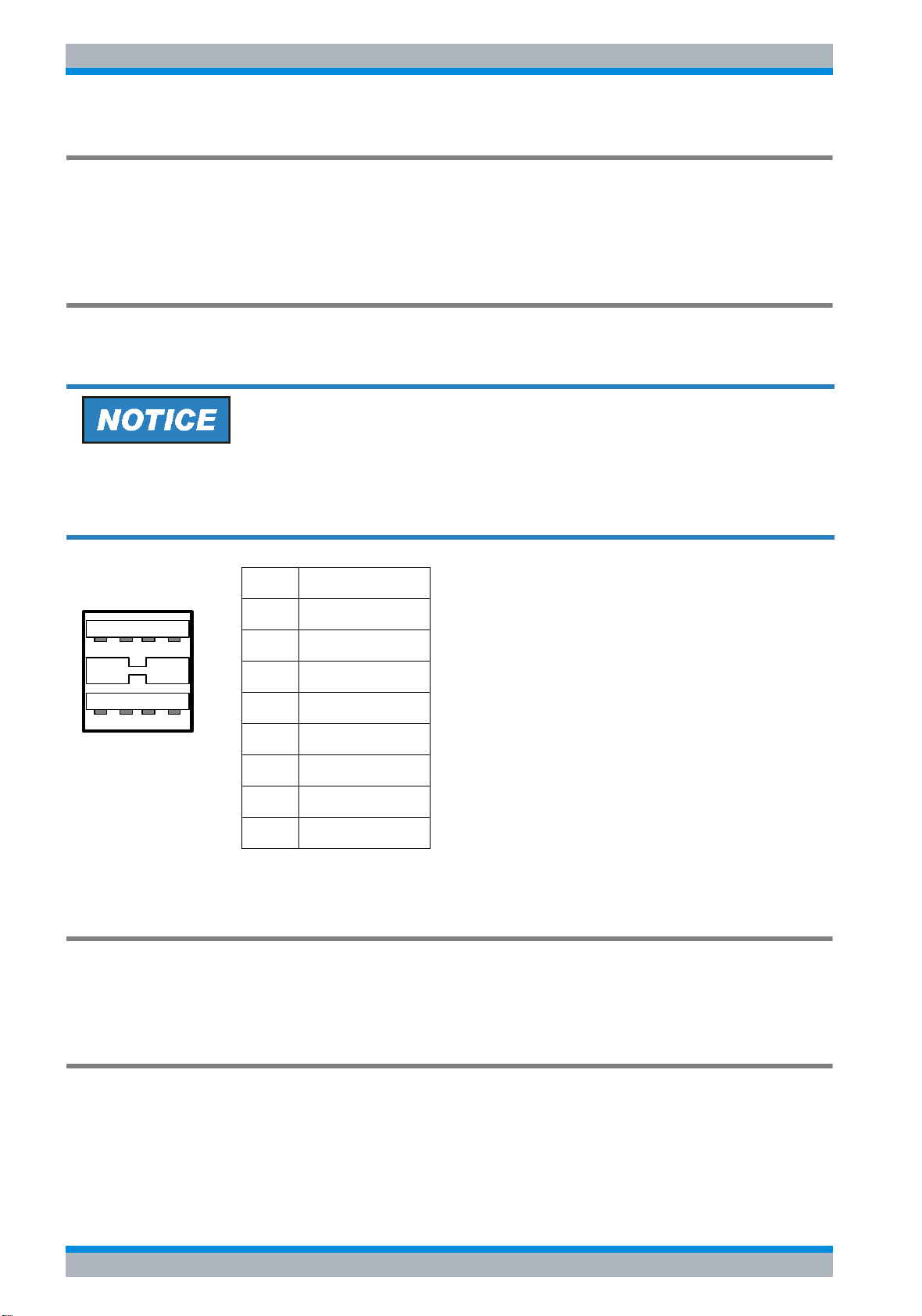
R&S ESU Front and Rear Panel
Rear Panel Connections
Input for External Trigger (EXT TRIG/GATE IN)
The EXT TRIG/GATE IN female connector is used to control the measurement by means of
an external signal.
The voltage levels are adjustable (0.5 V to 3.5 V). The typical input impedance is 10 kΩ.
USB Interface
The R&S ESU provides a USB female connector at the rear panel for connecting two USB
devices (upper connector USB 1.1, lower connector USB 2.0).
Use suitable double shielded cables. Passive USB connecting cables must not exceed 1 m
in length.
Use only USB devices that keep the permissible EMI limits.
Pin Signal
1 + 5 V USB0
1 2 3 4
5 6 7 8
2 USBDATA0 -
3 USBDATA0 +
4GND
5 + 5 V USB1
6 USBDATA1 -
7 USBDATA1 +
8GND
Fig. 1-8 USB connector assignment
Voltage output (SWEEP)
At this female BNC connector, sawtooth voltage proportional to the frequency is provided. The
output voltage ranges from 0 to 5 V.
USER PORT
The user interface is a 25 pin Cannon connector which provides access to the user port. The
port is 8 bits wide (A0 - A7) and can be configured either as output or as input. The voltage
levels are TTL levels (Low < 0,4 V, High > 2 V).
1.14 Quick Start Guide 1302.6163.62 - 05

R&S ESU Front and Rear Panel
Rear Panel Connections
In addition, the internal +5 V and +12 V power supply voltages are provided. The maximum
load current is 100 mA.
GND
+5 V
13
25
+12 V
GND
A7
A6
A5
A4
A3
A2
A1
1
14
A0
The user ports are configured in the SETUP menu (SETUP key), GENERAL SETUP /
USER PORT sub-menu.
Pin 21 (A7) is also used as ready-to-trigger signal (see also the Operating Manual, chapter 4,
section “User Port”).
Pin Signal Range of values
1 to 11 not used
12 ground
13 +5 V supply voltage 5.2 V ± 0.5 V, max. 30 mA
14 to 20 reserved
21 ready-for-trigger output signal HIGH: ≥ 1.4 V, LOW: ≤ 0.7 V
22 to 23 not used
24 ground
25 +12 V supply voltage +12 V ± 0.5 V, max. 10 mA
Reference Input and Output (REF IN and REF OUT)
The REF IN female connector is used as an input for a 10 MHz reference signal. The required
input level is 0 to 10 dBm. The REF OUT female connector provides the internal 10 MHz
reference signal with a 0 dBm output level for other devices.
The SETUP menu is used to select between the internal and external references.
If an external reference is used for operation, the external reference signal from REF IN is
looped through to REF OUT.
Use suitable double shielded cables.
Quick Start Guide 1302.6163.62 - 05 1.15

R&S ESU Front and Rear Panel
Rear Panel Connections
20.4 MHz IF Output (IF OUT 20.4 MHz)
The 20.4 MHz IF signal of the R&S ESU is provided at the 20.4 MHz OUT female BNC
connector. For resolution bandwidths between 100 kHz and 10 MHz, the bandwidth
corresponds to the selected bandwidth. For bandwidths ≤100 kHz, the bandwidth of the output
is equal to 2.6 * resolution bandwidth, where the minimum value is 2.6 kHz (non-FFT). In the
analyzer mode, the level at the IF output in the case of a signal at the reference level is 0 dBm
if the resolution bandwidth is ≥100 kHz; if the resolution bandwidth is <100 kHz, the level is
-10 dBm (for mixer levels ≥ -60 dBm).
Use suitable double shielded cables.
Video Output (VIDEO OUT)
In analyzer mode, the voltage of the analog detector (video) is output via the BNC connector
VIDEO OUT.
The video signal is unfiltered, i.e. the video bandwidth (VBW) setting on the instrument has no
effect on the video output. The usable video bandwidth is limited only by the set resolution
bandwidth (RBW) to approximately ½ * RBW.
The output voltage is always logarithmic, independent of the selected scaling on the display.
Likewise the selected detectors (e.g. RMS) affect only the display but not the video output. The
output impedance is 50 Ω. All subsequent voltage values are typical values and apply to the
output without load.
With RBW = 100 kHz as well as with all root raised cosine (RRC) and channel filters no video
signal is available.
RBW 200 kHz to 10 MHz
Output voltage at signal level = reference level: 1.8 V
Slope14 mV / dB
Exception: Ref_Level / dBm - RF_Attenuation / dB < -50
Output voltage at signal level = reference level:
1.8 V + (Ref_Level / dBm - RF_Attenuation / dB + 50) * 14 mV
TG I / AM IN; TG Q / FM IN (Option R&S FSU-B9)
The two female connectors TG I /AM IN and TG Q /FM IN are used to modulate the tracking
generator (option R&S FSU-B9) by means of an external signal.
The input voltage range is ±0.5 V; the input impedance is 50 Ω.
1.16 Quick Start Guide 1302.6163.62 - 05

R&S ESU Front and Rear Panel
Rear Panel Connections
LAN Interface
The LAN interface can be used to connect to a local network. The assignment of the RJ-45
connector supports twisted-pair category 5 UTP/STP cables in a star configuration (UTP
stands for “unshielded twisted pair”, and STP for “shielded twisted pair”).
Second GPIB Interface IEC2 (Option R&S FSP-B10)
When equipped with option R&S FSP-B10 (external generator control), the instrument
provides a second GPIB interface for using external generators.
ATN IFC NRFD EOI DIO 3 DIO1
SHIELD SRQ NDAC DAV DIO4 DIO2
12
24
LOGIC GND GND(10) GND(8) GND(6) DIO8 DIO6
GND(11) GND(9) GND(7) REN DIO7 DIO5
1
13
Fig. 1-9 Pin assignment of the second IEC interface
The R&S ESU remote control is not supported via the second GPIB
interface.
Quick Start Guide 1302.6163.62 - 05 1.17

R&S ESU Front and Rear Panel
Rear Panel Connections
AUX CONTROL (Option R&S FSP-B10)
If option R&S FSP-B10 (external generator control) is built in, the R&S ESU provides a female
connector that allows measurement data acquisition to be synchronized with the output signal
of a Rohde & Schwarz generator.
Blank
n.c.
n.c.
Trigger
n.c.
GND
34
GND
5
GND
1
2
6789
GND
Pin Signal Description
1 n.c. not connected
2 BLANK Return signalling from the signal generator indicating that frequency
setting is completed
3 TRIGGER Trigger signal for switching to the next frequency
6...9 GND Ground
Fig. 1-10 Pin assignment of the AUX CONTROL connector
1.18 Quick Start Guide 1302.6163.62 - 05

R&S ESU Preparing for Use
2 Preparing for Use
2.1 Preparing for Operation . . . . . . . . . . . . . . . . . . . . . . . . . . . . 2.4
2.1.1 Unpacking the Instrument . . . . . . . . . . . . . . . . . . . . . . . . 2.4
2.1.2 Setting Up the Instrument . . . . . . . . . . . . . . . . . . . . . . . . 2.5
2.1.3 Installation in a 19" Rack . . . . . . . . . . . . . . . . . . . . . . . . . 2.6
2.1.4 Connecting the Instrument to the AC Power Supply . . . . 2.6
2.1.5 Switching On the R&S FSP . . . . . . . . . . . . . . . . . . . . . . . 2.6
2.1.6 Functional Test . . . . . . . . . . . . . . . . . . . . . . . . . . . . . . . . . 2.7
2.1.7 Switching Off the R&S FSP . . . . . . . . . . . . . . . . . . . . . . . 2.8
2.1.8 Cleaning the Outside . . . . . . . . . . . . . . . . . . . . . . . . . . . . 2.8
2.2 Instrument Drive Usage . . . . . . . . . . . . . . . . . . . . . . . . . . . . 2.9
2.3 Connecting External Devices . . . . . . . . . . . . . . . . . . . . . . 2.10
2.3.1 Connecting an External Keyboard . . . . . . . . . . . . . . . . . 2.10
2.3.2 Connecting a Mouse . . . . . . . . . . . . . . . . . . . . . . . . . . . 2.14
2.3.3 Connecting an External Monitor . . . . . . . . . . . . . . . . . . 2.15
2.3.4 Connecting a Printer . . . . . . . . . . . . . . . . . . . . . . . . . . . 2.16
2.3.5 Connecting USB Devices (e.g. a Power Meter) . . . . . . . 2.18
2.3.6 Connecting External Generators . . . . . . . . . . . . . . . . . . 2.21
2.3.6.1 Connecting the R&S FSP to the Generator . . . . . . . 2.24
2.3.6.2Configuring the Generator on the R&S FSP . . . . . . . 2.25
2.3.6.3Activating the Generator Configuration and Setting
the Output Level . . . . . . . . . . . . . . . . . . . . . . . . . . . . . . . . . 2.27
Quick Start Guide 1302.6163.62 - 05 2.1

R&S ESU Preparing for Use
2.3.6.4Using an External Generator as a Tracking
Generator . . . . . . . . . . . . . . . . . . . . . . . . . . . . . . . . . . . . . . . 2.29
2.4 Setup . . . . . . . . . . . . . . . . . . . . . . . . . . . . . . . . . . . . . . . . . . . 2.31
2.4.1 Selecting the Frequency Reference . . . . . . . . . . . . . . . . 2.31
2.4.2 Setting the Date and Time . . . . . . . . . . . . . . . . . . . . . . . 2.31
2.4.3 Setting the GPIB Interface . . . . . . . . . . . . . . . . . . . . . . . 2.33
2.4.3.1 GPIB Address . . . . . . . . . . . . . . . . . . . . . . . . . . . . . 2.33
2.4.3.2 GPIB Language . . . . . . . . . . . . . . . . . . . . . . . . . . . . 2.33
2.4.3.3 ID Response String . . . . . . . . . . . . . . . . . . . . . . . . . 2.38
2.4.4 Setting the Screen Colors . . . . . . . . . . . . . . . . . . . . . . . 2.39
2.4.5 Automatically Switching Off the Internal Screen . . . . . . 2.40
2.4.6 File and Path Selection Using the Front Panel Keys . . . 2.41
2.4.7 Selecting and Configuring Printers . . . . . . . . . . . . . . . . . 2.43
2.4.7.1 Selecting Alternative Printer Configurations . . . . . . 2.44
2.4.7.2 Selecting Printer Colors . . . . . . . . . . . . . . . . . . . . . . 2.44
2.5 Configuring the LAN Interface . . . . . . . . . . . . . . . . . . . . . . 2.49
2.5.1 Connecting the Instrument to the Network . . . . . . . . . . . 2.49
2.5.2 Configuring the Network Card . . . . . . . . . . . . . . . . . . . . 2.50
2.5.2.1 Configuring the Interface . . . . . . . . . . . . . . . . . . . . . 2.50
2.5.2.2 Configuring Existing Network Protocols (TCP/IP
Protocol) . . . . . . . . . . . . . . . . . . . . . . . . . . . . . . . . . . . . . . . . 2.51
2.5.2.3 Installing Additional Network Protocols and
Services . . . . . . . . . . . . . . . . . . . . . . . . . . . . . . . . . . . . . . . . 2.57
2.5.3 Login . . . . . . . . . . . . . . . . . . . . . . . . . . . . . . . . . . . . . . . 2.58
2.6 Operating System Properties . . . . . . . . . . . . . . . . . . . . . . . 2.63
2.6.0.1 Windows Service Packs . . . . . . . . . . . . . . . . . . . . . . 2.63
2.6.0.2 Opening the Windows Start Menu . . . . . . . . . . . . . . 2.64
2.2 Quick Start Guide 1302.6163.62 - 05

R&S ESU Preparing for Use
Preparing for Operation
2.1 Preparing for Operation
This section describes how to put the instrument into operation.
Before putting the instrument into operation, make sure that the following requirements
have been met:
• The air vents are not blocked.
• No signal voltage levels exceeding the permitted limits are present at the inputs.
• The instrument's outputs are neither overloaded nor incorrectly connected.
Not complying with these requirements can result in damage to the instrument.
2.1.1 Unpacking the Instrument
➢ Remove the instrument from its packaging and check the equipment for completeness
using the delivery note and the accessory lists for the various items.
➢ First, pull off the polyethylene protection pads from the instrument's rear feet and then
carefully remove the pads from the instrument handles at the front.
➢ Pull off the corrugated cardboard cover that protects the rear of the instrument.
➢ Carefully unthread the corrugated cardboard cover at the front that protects the instrument
handles and remove it.
➢ Check the instrument for any damage. If there is damage, immediately contact the carrier
who delivered the instrument. In this case, make sure not to discard the box and packing
material.
It is advisable to keep the original packing material in order to prevent control elements and
connectors from being damaged in case the instrument is to be transported or shipped at a
later date.
Protective plastic caps for the front panel and the rear panel can be ordered addditionally
(order number 1096.7095.00). Please note that you need to order 2 covers for 1 instrument.
Quick Start Guide 1302.6163.62 - 05 2.3
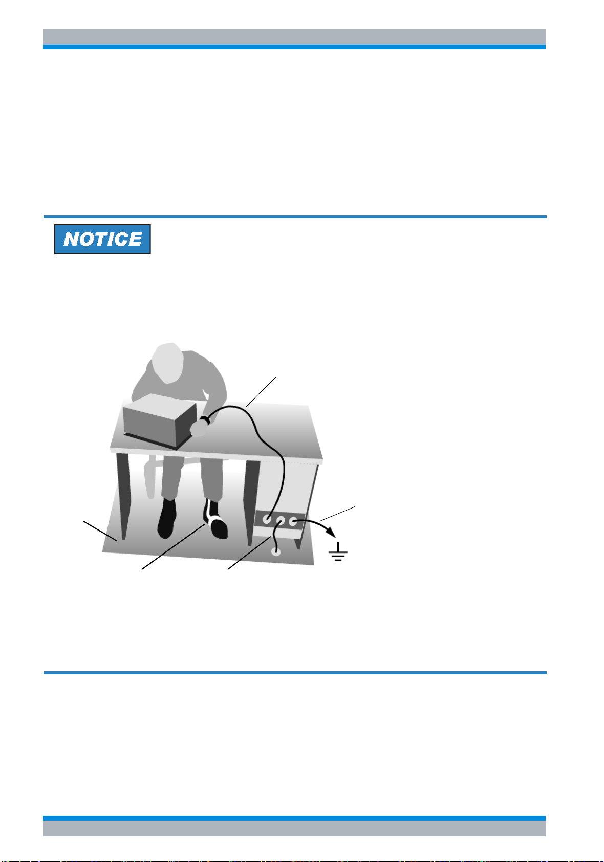
R&S ESU Preparing for Use
Preparing for Operation
2.1.2 Setting Up the Instrument
The instrument is intended for indoor use. Note the following in this regard:
• The ambient temperature must comply with the range specified in the data sheet.
• Air inflow and outflow via the air vents on the rear panel and through the lateral perforations
must not be obstructed. Clearance from walls must be at least 10 cm.
• The mounting surface must be even.
Risk of damaging electronic components
To avoid damage of electronic components, the operational site must be protected against
electrostatic discharge (ESD).
Wrist strap with cord
Building ground
Floor mat
Heel strap
Ground connection
of operational site
The following two methods of ESD protection may be used together or separately:
• Wrist strap with cord to ground connection
• Conductive floor mat and heel strap combination
2.4 Quick Start Guide 1302.6163.62 - 05

R&S ESU Preparing for Use
Preparing for Operation
2.1.3 Installation in a 19" Rack
The instrument can be installed in a 19" rack by using a rack adapter (see data sheet for order
number). The installation instructions are included with the adapter.
When the instrument is installed in a rack, make sure that the vents for air inflow on the side
panel and the air outlets on the rear panel are not obstructed.
2.1.4 Connecting the Instrument to the AC Power Supply
The R&S ESU is equipped with a mechanism for detecting AC power voltage and
automatically sets itself to use the available AC power voltage (range: AC voltage 100 V to
240 V; 50 Hz to 400 Hz). The AC power connector is located on the rear panel of the
instrument.
➢ Connect the R&S ESU to the AC power supply, using the power cable that
I
o
is supplied.
Since the instrument is assembled in line with the specifications for safety
AC power
connector
class EN61010, it may only be connected to an outlet that has a ground
contact.
2.1.5 Switching On the R&S ESU
➢ Press the power switch on the real panel to change it to position I.
➢ Press the ON/STANDBY key on the front panel. The green LED will light up.
Do not switch off the instrument while it is booting.
Switching it off prematurely can lead to serious data changes on the instrument's hard disk.
After being switched on, the R&S ESU displays the following information:
Rohde & Schwarz GmbH & Co. KG
Analyzer BIOS Vx.y
A self test of the computer hardware will be carried out. Windows XP then starts, and the
measurement screen will automatically appear with the settings that were present when the
instrument was last switched off.
If you want the instrument to automatically load different settings when
it is switched on, define the required configuration in the FILE -
STARTUP RECALL menu.
Quick Start Guide 1302.6163.62 - 05 2.5
R&S ESU Preparing for Use
Preparing for Operation
2.1.6 Functional Test
The functional test should only be performed when the operating
temperature is reached (approx. 15 minutes after the instrument is
switched on).
➢ Call self alignment with the CAL key, CAL TOTAL softkey. Once the system correction
values have been calculated successfully, the message Calibration Passed will appear.
➢ Start the self test with the SETUP key, SERVICE – SELFTEST softkeys. Once the
instrument modules have been checked successfully, the message Selftest Passed will
appear.
Once both steps have been completed successfully, the instrument will be ready for operation.
The self alignment does not need to be repeated every time the
instrument is switched on, because the instrument saves the values
and loads them during booting automatically. A self alignment is
recommended if the instrument is used at a temperature that differs
considerable (more than 10°C) from the temperature present at the last
self alignment.
The self test also does not need to be repeated every time the
instrument is switched on. It is necessary only when instrument
malfunction is suspected.
2.6 Quick Start Guide 1302.6163.62 - 05

R&S ESU Preparing for Use
Preparing for Operation
2.1.7 Switching Off the R&S ESU
➢ Press the ON/STANDBY key on the front panel.
The R&S ESU will store the current settings on the hard disk and then shut down the
software. Once the operation has been completed, the power supply unit will be switched
to STANDBY and the yellow LED will come on.
Shock hazard
In standby mode, the AC supply voltage is still present on the instrument.
➢ To completely disconnect the instrument from the AC power supply, change the power
switch on the rear panel to position O.
• The main power switch on the rear panel also interrupts the power
supply of the OCXO (optional) inside the instrument. When you
switch the instrument back on, be sure to adhere to the extended
warm-up phase.
• If you switch off the instrument by using the power switch or by
disconnecting the power supply connector, it is not possible to save
the current instrument settings on the hard disk. In this case, the last
settings that were stored on the hard disk will be loaded when you
switch the instrument back on.
2.1.8 Cleaning the Outside
The outside of the instrument is suitably cleaned using a soft, line-free dust cloth. Make sure
that the air vents are not obstructed.
Cleaning agents contain substances that may damage the instrument, e.g. solventcontaining cleaning agents may damage the front panel labeling or plastic parts.
Never use cleaning agents such as solvents (thinners, acetone, etc.), acids, bases, or other
substances.
Quick Start Guide 1302.6163.62 - 05 2.7

R&S ESU Preparing for Use
Instrument Drive Usage
2.2 Instrument Drive Usage
The harddisk space is divided in 3 logical drives (2 with option R&S ESU-B18):
The harddisk space is divided in 3 logical drives.
C:
Contains the operating system Windows, printer driver, network driver,…
Other user programs, applications, driver should be stored/installed on drive C:.
D:
Contains instrument's firmware and related data sets (limit lines, transducers,...)
D:\user\config is the default location for customized instrument settings
D:\R_S\instr\temp is the default directory for hardcopy files.
Other user data should be stored on drive D:.
2.8 Quick Start Guide 1302.6163.62 - 05

R&S ESU Preparing for Use
Connecting External Devices
2.3 Connecting External Devices
2.3.1 Connecting an External Keyboard
Do not connect the keyboard unless the instrument is switched off (STANDBY). Otherwise,
proper functioning cannot be ensured due to interactions with the firmware.
An external PC keyboard can be connected to the USB interface on the front or the rear panel
of the R&S ESU.
USB
The keyboard simplifies instrument operation and the entry of comments, file names, etc.
Keyboards and mouse devices conform to USB Standards 1.1 or 2.0 are suitable for
connection to the USB interface.
After being connected, the keyboard is automatically detected. The default keyboard language
setting is US English. Special settings such as refresh rate, etc. can be made by opening the
Windows Control Panel by selecting START - CONTROL PANEL. In the search field enter
„keyboard“. Select KEYBOARD and the KEYBOARD PROPERTIES dialog opens.
2.3.2 Connecting a Mouse
To simplify Windows operation, the R&S ESU allows you to connect a mouse to one of the
USB interfaces on the front or rear panel or the PS/2 mouse connector on the rear panel.
USB
Mouse devices from Microsoft and Logitech are supported.
If you use a keyboard that contains a trackball for mouse operations,
connecting an external mouse in addition may lead to malfunctions.
Quick Start Guide 1302.6163.62 - 05 2.9

R&S ESU Preparing for Use
Connecting External Devices
After being connected, the mouse is automatically detected. Special settings such as mouse
cursor speed, etc. can be made by opening the Windows Control Panel START - CONTROL
PANEL. In the search field enter „mouse“. Select MOUSE and the MOUSE PROPERTIES
opens.
2.3.3 Connecting an External Monitor
Do not connect a monitor unless the instrument is switched off (STANDBY). Otherwise, you
run the risk of damaging the monitor.
You can connect an external monitor at the MONITOR connector on the instrument's rear
panel.
MONITOR
After connecting the external monitor, restart the instrument to detect the monitor. The
measurement display will then appear on both the external screen and on the instrument. No
further settings are necessary.
If the external monitor is not recognized by the instrument, you have to activate it. This
requires a mouse and an external keyboard (the connection is described in sections
“ Connecting a Mouse” on page 2.14 and “ Connecting an External Keyboard” on page 2.10).
2.3.4 Connecting a Printer
A printer can be connected during operation.
The R&S ESU allows you to create two different printer configurations for printing out a
hardcopy of the screen and you can toggle between them by pressing a button. The DEVICES
table in the HCOPY menu lists the available installed printers.
The LPT printer interface is located on the rear panel. Alternatively, one of the USB interfaces
on the front or rear panel can be used.
LPT
USB
2.10 Quick Start Guide 1302.6163.62 - 05

R&S ESU Preparing for Use
Connecting External Devices
2.3.5 Connecting USB Devices (e.g. a Power Meter)
The USB interface on the front and the rear panel of the R&S ESU allows you to connect up
to 4 USB devices directly to the R&S ESU. This number can be increased as necessary by
inserting USB hubs.
Due to the large number of available USB devices, there is almost no limit to the expansions
that are possible with the R&S ESU. The following list shows various USB devices that can be
useful for the R&S ESU:
• Power sensors of the R&S NRP-Zxx series
(require adapter cable R&S NRP-Z4)
• Memory stick for easy transfer of data to/from a PC
(e.g. firmware updates)
• CD-ROM drives for easy installation of firmware applications
• PC keyboard for entering comments, file names, etc.
• Mouse for easy operation of Windows dialog boxes
• Printer for printing out measurement results
• Modem for remote control of the R&S ESU over large distances
Installing USB devices is easy under Windows, because all USB devices are plug&play. All
USB devices can be connected to or disconnected from the R&S ESU during operation.
After a device is connected to the USB interface of the R&S ESU, Windows automatically
searches for a suitable device driver.
If Windows does not find a suitable driver, it will prompt you to specify a directory that contains
the driver software. If the driver software is on a CD, connect a USB CD-ROM drive to the
R&S ESU before proceeding.
When a USB device is subsequently disconnected from the R&S ESU, Windows immediately
detects the change in hardware configuration and deactivates the corresponding driver.
Quick Start Guide 1302.6163.62 - 05 2.11

R&S ESU Preparing for Use
Connecting External Devices
2.3.6 Connecting External Generators
The External Generator Control option (R&S FSP-B10) allows you to operate a number of
commercially available generators as a tracking generator on the R&S ESU. When suitable
generators are used, the R&S ESU thus allows scalar network analysis to be performed also
outside the frequency range of the internal tracking generator. Appendix “External Generator
Control” provides a list of generators supported by the option R&S FSP-B10.
The following figure shows the test setup:
The generator is controlled via the – optional – second GPIB interface of the R&S ESU
(= IEC2, supplied together with the option). With some Rohde & Schwarz generators, it is also
controlled via the TTL synchronization interface that is contained in the AUX CONTROL
interface of the R&S ESU.
• Using the TTL interface allows you to attain significantly higher
speeds than possible with a pure GPIB control, because the
frequency switching mechanism of the R&S ESU is directly coupled
to the frequency switching mechanism of the generator.
• To increase measurement accuracy, use a shared reference
frequency to operate the R&S ESU and the generator. If no
independent 10 MHz reference frequency is available, connect the
reference output of the generator to the reference input of the
R&S ESU and use SETUP – REFERENCE EXT to configure the
R&S ESU to implement the external reference.
2.12 Quick Start Guide 1302.6163.62 - 05

R&S ESU Preparing for Use
Connecting External Devices
2.3.6.1 Connecting the R&S ESU to the Generator
To couple the frequency setting and level setting of the generator to the R&S ESU, set up the
following connections:
1. Connect the GPIB interface of the generator to the IEC2 connector on the rear panel of the
R&S ESU.
2. (Optional:) Connect the TTL interface of the generator and the R&S ESU.
➢ Alternative 1 (R&S SMR, R&S SMU):
Connect the AUX CONTROL connector of the R&S ESU to the corresponding AUX
connector on the rear panel of the generator (the connection cable is supplied together
with the option R&S FSP-B10).
➢ Alternative 2 (R&S SME, R&S SMP, R&S SMIQ):
Connect the AUX CONTROL connector of the R&S ESU to the TRIGGER, MARKER
and BLANK connectors on the rear panel of the generator (the connection cable is also
supplied together with the option R&S FSP-B10). Note the labelling on the TRIGGER,
MARKER and BLANK lines.
➢ Alternative 3 (R&S SML, R&S SMG/SMGU, R&S SMH/SMHU, R&S SMX/SMY,
generators from other manufacturers):
No TTL connection possible.
The generator type determines which one of the possible connections is suitable for the
generator. For more information, refer to the Operating Manual for the generator.
3. Connect the reference frequency output of the generator to the reference frequency input
(REF IN) of the R&S ESU.
or
Connect the reference frequency inputs of the two instruments to an external frequency
standard.
2.3.6.2 Configuring the Generator on the R&S ESU
To configure the generator, change into the NETWORK mode:
➢ Press the SPECTRUM hotkey to change to the analyzer mode.
➢ Press the NETWORK hotkey located in the hotkey bar at the lower edge of the screen.
Perform the following steps:
1. Press the EXT SOURCE softkey. The submenu for configuring generators will open
2. Select and configure the generator:
➢ Press the SELECT GENERATOR softkey.
The table containing the generator settings will open. The selection bar will be located in
the row SRC 1 under the column TYPE.
Quick Start Guide 1302.6163.62 - 05 2.13

R&S ESU Preparing for Use
Connecting External Devices
➢ Press the ENTER key.
The list of available generators will open.
➢ Using the rotary knob, select the desired generator and activate ENTER by pressing the
rotary knob.
The generator list will close, and the selected generator will then appear in the SELECT
GENERATOR table. Simultaneously, the limits for frequency and output power which
you can set on the generator will appear in the F MIN, F MAX, P MIN and P MAX fields.
➢ Using the Ur key, move the selection bar to the IFC column and press the ENTER key.
The list of available control interfaces will appear.
➢ If the TTL interfaces from the R&S ESU and generator are connected, select TTL by
using the rotary knob and then activate it by pressing the rotary knob.
➢ If no TTL interface is provided or if the TTL interfaces are not connected, select GPIB by
using the rotary knob and then activate it by pressing the rotary knob.
➢ Using the Ur key, move the selection bar to the GPIB ADDR column and press the
ENTER key.
The entry field for the GPIB address of the generator will open.
➢ Enter the GPIB address of the generator and confirm with ENTER.
The specified address will be added to the table.
3. Select the reference frequency for the generator:
➢ If you want to operate the generator using its internal reference, change the GEN REF
softkey to the state INT.
➢ If you want to operate the generator using an external reference, change the GEN REF
softkey to the state EXT.
This concludes the procedure for defining the default setting for the generator.
A second generator configuration can be inserted in advance by
repeating the settings in the line SRC 2. This makes it easy to switch
from one generator type to another.
2.3.6.3 Activating the Generator Configuration and Setting the Output Level
To select the active generator configuration, press the FREQUENCY SWEEP softkey. The
FREQUENCY SWEEP table will open, and the selection bar will be located under the STATE
column in the SRC 1 row.
➢ If you want to use the SRC 1 generator configuration, insert a checkmark in the field by
pressing the ENTER key.
2.14 Quick Start Guide 1302.6163.62 - 05

R&S ESU Preparing for Use
Connecting External Devices
➢ If you want to use the SRC 2 generator configuration, move the selection bar to the lower
line of the table by using the Ud key. Then activate the generator configuration by pressing
the ENTER key and set the checkmark in line 2 under the STATE column.
➢ Using the Ur key, move the selection bar to the POWER [dBm] column and press the
ENTER key.
➢ Enter the desired output power and confirm with the dBm key. The power you entered will
appear in the table.
You can also change the output power of the generator by using the
SOURCE POWER softkey located in the NETWORK menu.
The remaining columns of the table are used to configure frequency-converting
measurements. For more information, refer to the Operating Manual, section "External
Generator Control - Option R&S FSP-B10".
This concludes the procedure for configuring the generator.
2.3.6.4 Using an External Generator as a Tracking Generator
To activate the external generator as a tracking generator, do the following:
➢ Switch on the external generator.
➢ Press the SPECTRUM hotkey to change to the analyzer mode.
➢ Press the NETWORK hotkey on the R&S ESU.
➢ Press the EXT SOURCE softkey.
Tracking generator operation using an external generator will be activated. The external
generator will switch to remote control and can be used like an internal tracking generator. For
more information about measurements with an external tracking generator, refer to the
Operating Manual, section "External Generator Control - Option R&S FSP-B10".
Switching off the tracking generator:
➢ Press the NETWORK hotkey on the R&S ESU.
➢ Press the EXT SOURCE softkey.
➢ Change the EXT SRC softkey to OFF by pressing it.
When you switch off tracking generator operation using an external
generator, control on the IEC2 is automatically released and the
generator is returned to LOCAL mode.
Quick Start Guide 1302.6163.62 - 05 2.15

R&S ESU Preparing for Use
Setup
2.4 Setup
2.4.1 Selecting the Frequency Reference
You can switch the reference signal for frequency processing of the R&S ESU between the
internal reference and an external reference signal at 10 MHz as follows:
➢ Press the SETUP key.
The SETUP menu will open.
➢ Press the REFERENCE INT/EXT softkey until it is in the desired state.
If the reference signal is missing when switchover to the external
reference occurs, EXREF is displayed after a few moments, indicating
that synchronization has not taken place.
When switchover to an internal reference occurs, note that the external
reference signal is removed in order to avoid any interactions with the
internal reference signal.
IEC bus command: ROSC:SOUR INT
2.4.2 Setting the Date and Time
➢ Press the SETUP key.
The SETUP menu will open.
➢ Press the GENERAL SETUP softkey.
The submenu with general settings will open.
The TIME+DATE softkey activates the TIME AND DATE table for entering the time and
date for the internal real-time clock.
Entering the time
Hours and minutes can be entered independently of each other in the entry field:
IEC bus command: SYST:TIME 12,30
2.16 Quick Start Guide 1302.6163.62 - 05

R&S ESU Preparing for Use
Setup
Entering the date
The day, month and year can be entered independently of each other in the entry field:
To select the month, use the units key to open a list containing the month names. You can
then select the month from the list.
IEC bus command: SYST:DATE 2002,03,11
2.4.3 Setting the GPIB Interface
➢ Press the SETUP key.
The SETUP menu will open.
➢ Press the GENERAL SETUP softkey.
The submenu with general settings will open.
➢ Press the GPIB softkey.
The submenu for setting the parameters of the remote control interface will open.
2.4.3.1 GPIB Address
➢ Press the GPIB ADDRESS softkey.
The entry field for the GPIB address will open.
The setting range is from 0 to 30. The default address is 20 if SCPI is selected as the GPIB
language or 18 if an 85xx emulation is selected.
IEC bus command: SYST:COMM:GPIB:ADDR 20
Quick Start Guide 1302.6163.62 - 05 2.17

R&S ESU Preparing for Use
Setup
2.4.3.2 GPIB Language
➢ Press the GPIB LANGUAGE softkey.
The list of available remote control languages will open.
The following languages are available:
•SCPI
• HP mode:
8560E, 8561E, 8562E, 8563E, 8564E, 8565E, 8566A, 8566B, 8568A, 8568A_DC,
8568B, 8568B_DC, 71100C, 71200C, 71209A, 8591E, 8594E
If entries of the HP mode are selected, the command recognition uses
syntax rules which are different from syntax rules of the SCPI mode.
Correspondingly, proper detection of SCPI commands is not ensured
in this mode.
For 8566A/B, 8568A/B and 8594E, command sets A and B are
available. Command sets A and B differ in the rules regarding the
command structure.
Selecting a language different from "SCPI" will set the GPIB address to
18 if it was 20 before.
Start / stop frequency, reference level and # of sweep points will be
adapted to the selected instrument model.
8568A_DC and 8568B_DC are using DC input coupling as default if it
is supported by the instrument.
The HP model 8591E is compatible to HP model 8594E, the HP models
71100C, 71200C, and 71209A are compatible to HP models 8566A/B.
When the selection is changed, the following settings are changed:
SCPI:
• The instrument will perform a preset.
71100C, 71200C, 71209A, 856xA/B, 856xE, 8591E, 8594E:
• The instrument will perform a preset.
The following instrument settings will then be changed:
Model # of Trace
Points
Start Freq. Stop Freq. Ref Level Input Coupling
8560E 601 0 Hz 2.9 GHz 0 dBm AC
8561E 601 0 Hz 6.5 GHz 0 dBm AC
8562E 601 0 Hz 13.2 GHz 0 dBm AC
8563E 601 0 Hz 26.5 GHz 0 dBm AC
8564E 601 0 Hz 40 GHz 0 dBm AC
2.18 Quick Start Guide 1302.6163.62 - 05

R&S ESU Preparing for Use
Setup
Model # of Trace
Points
8565E 601 0 Hz 50 GHz 0 dBm AC
8566A/B 1001 2 GHz 22 GHz 0 dBm DC (R&S ESU)
8568A/B 1001 0 Hz 1.5 GHz 0 dBm AC
8591E 401 0 Hz 3 GHz 0 dBm AC
8594E 401 0 Hz 3 GHz 0 dBm AC
71100C 1001 2 GHz 22 GHz 0 dBm DC (R&S ESU)
71200C 1001 2 GHz 22 GHz 0 dBm DC (R&S ESU)
71209A 1001 2 GHz 22 GHz 0 dBm DC (R&S ESU)
Start Freq. Stop Freq. Ref Level Input Coupling
Note regarding the selection of 856x for the R&S ESU:
• The # of trace points is not switched over until the state changes to
REMOTE. In the case of switchover to manual operation (LOCAL
key), the number of sweep points is always changed to 625.
• If necessary, the stop frequency specified in the table is restricted to
the corresponding frequency range of the R&S ESU.
IEC bus command: SYST:LANG "SCPI" | "8560E" | "8561E" | "8562E" |
"8563E" | "8564E" | "8565E" | "8566A" | "8566B" |
"8568A" | "8568A_DC" | "8568B" | "8568B_DC" |
"8591E" | "8594E" | "71100C" | "71200C" | "71209A"
2.4.3.3 ID Response String
➢ The ID STRING FACTORY softkey selects the default response to the command *IDN?.
IEC bus command: --
➢ The ID STRING USER softkey opens the editor for entering a user-defined response to the
command *IDN?. The max. length of the output string is 36 characters.
IEC bus command: --
Quick Start Guide 1302.6163.62 - 05 2.19

R&S ESU Preparing for Use
Setup
2.4.4 Setting the Screen Colors
➢ Press the DISP key.
The DISPLAY menu will open.
➢ Press the CONFIG DISPLAY softkey.
The submenu for configuring the screen will open.
➢ The DEFAULT COLORS 1 and 2 softkeys set the default setting for brightness, tint and
color saturation of all screen objects. The color schemes are selected in such a manner that
all screen elements will be optimally visible regardless whether viewed from above or
below. In the instrument's default setting, DEFAULT COLORS 1 is active.
IEC bus command: DISP:CMAP:DEF1
DISP:CMAP:DEF2
The procedure for setting screen colors and brightness is as follows:
➢ Press the NEXT key.
The side menu for changing the screen colors will open.
The SELECT OBJECT softkey activates the selection of screen elements for which the
color setting needs to be changed. Once this selection is made, the PREDEFINED
COLORS, BRIGHTNESS, TINT and SATURATION softkeys can be used to change the
overall color or the brightness, tint and color saturation of the selected element.
The BRIGHTNESS softkey activates entry of the brightness of the selected graphics
element.
The entry value is between 0% and 100%.
IEC bus command: DISP:CMAP5:HSL <hue>,<sat>,<lum>
2.20 Quick Start Guide 1302.6163.62 - 05

R&S ESU Preparing for Use
Setup
The TINT softkey activates entry of the tint for the selected graphics element. The percent
value that is entered refers to a continuous color spectrum that ranges from red (0%) to blue
(100%).
IEC bus command: DISP:CMAP5:HSL <hue>,<sat>,<lum>
The SATURATION softkey activates entry of the color saturation of the selected element.
The entry value is between 0% and 100%.
IEC bus command: DISP:CMAP5:HSL <hue>,<sat>,<lum>
The PREDEFINED COLORS softkey opens a list for selecting predefined colors for the
screen objects:
IEC bus command: DISP:CMAP1 ... 26:PDEF <color>
2.4.5 Automatically Switching Off the Internal Screen
The R&S ESU provides a feature for automatically switching off the screen after a userdefined period of time. The background lighting will be disabled if no entries are made from
the front panel after the selected response time (key, softkey or hardkey and rotary knob).
To activate automatic switch-off:
➢ Press the DISP key.
➢ Press the CONFIG DISPLAY softkey.
➢ Press the DISPLAY PWR SAVE softkey.
The softkey will have a color background, indicating that the power save mode
is active. At the same time, the input window for the response time will open.
➢ Enter the desired response time in minutes and confirm the entry with the ENTER key.
The screen will be disabled (turn dark) after the selected period of time.
To deactivate automatic switch-off:
➢ Press the DISP key.
➢ Press the CONFIG DISPLAY softkey.
➢ Press the DISPLAY PWR SAVE softkey twice.
The color background of the softkey will disappear.
The power save mode is now switched off.
Quick Start Guide 1302.6163.62 - 05 2.21

R&S ESU Preparing for Use
Setup
2.4.6 File and Path Selection Using the Front Panel Keys
As of firmware version 4.3x the base system firmware supports new dialog boxes to select a
folder and/or a file, e.g. for trace export.
The following section describes the usage of the instrument's front panel keys using TRACE
EXPORT as an example.
➢ Press the TRACE key and then the NEXT softkey.
➢ Press the ASCII FILE EXPORT softkey to open the corresponding dialog box.
The focus is on the File Name field so you can directly edit the file name using the numeric
keys, the cursor keys or the BACK key.
You can also use alphanumeric characters in the file name.
➢ To enter alphanumeric characters, select the EDIT FILENAME button. Confirm the
selection with the ENTER key to open an online keyboard.
Select the characters with the rotary knob or the cursor keys and confirm with the ENTER
key.
2.22 Quick Start Guide 1302.6163.62 - 05

R&S ESU Preparing for Use
Setup
➢ Drive usage is checked according to the following rules:
• first, the R&S ESU checks for a connected memory stick
• if a memory stick is not recognized, then the R&S ESU uses the internal hard disk.
Note that the path and file name are reset to their default values after an instrument
PRESET.
➢ Change the drive by moving the rotary knob until the focus is on the Save In field.
➢ Press the CURSOR RIGHT key to open the dropdown menu and select the drive you want
to save the file to with the CURSOR UP and CURSOR DOWN keys. Confirm your selection
by pressing the ENTER key.
➢ Select a subfolder by moving the rotary knob until the file / subfolder list is in focus. The
selected file or subfolder in focus is framed by dotted line.
➢ Use the CURSOR UP or CURSOR DOWN keys to select a specific folder or file. To change
the path or select a file, confirm your selection with the ENTER key.
Note that the R&S ESU overwrites existing files with the new data.
Quick Start Guide 1302.6163.62 - 05 2.23

R&S ESU Preparing for Use
Setup
2.4.7 Selecting and Configuring Printers
➢ Press the HCOPY key.
The HARDCOPY menu will open.
➢ Press the DEVICE SETUP softkey.
The dialog box for selecting the file format and printer will open:
➢ You can select a connected printer (including a pre-configured network printer) by
positioning the selection bar on the Printer entry by turning the rotary knob and then
confirming the selection by pressing the rotary knob or the ENTER key.
After you confirm the selection, the entries Name, Print to File and Orientation will be made
available and can also be accessed with the rotary knob.
➢ To select the printer type, open the selection list by pressing the rotary knob or the ENTER
key after you access the Name field.
From the selection list, you can now select the printer you want (in the example, this is
Cannon Bubble-Jet BJC800 (A4)) by using the rotary knob again and then confirming your
selection with ENTER or by pressing the rotary knob. The selection list will then disappear
and the entry cursor will return to the Name field.
2.24 Quick Start Guide 1302.6163.62 - 05

R&S ESU Preparing for Use
Setup
➢ You can also redirect the output to a file rather than to a printer. To do this, select the field
Print to File by using the rotary knob and then mark the appropriate selection box or cancel
the marking by pressing either the rotary knob or the ENTER key:
➢ You can select orientation for paper printout by using the Orientation field. To open the
selection list, press the rotary knob or ENTER:
From the selection list, you can now select the orientation you want (Portrait in the
preceding figure) by using the rotary knob again and then confirm with ENTER or by
pressing the rotary knob. The selection list will then close and the entry cursor will return to
the Orientation field.
You can now close the dialog box by pressing the ESC key or by selecting and confirming
the Close button.
2.4.7.1 Selecting Alternative Printer Configurations
The R&S ESU can support two independent hardcopy settings. This allows you to quickly
switch between output to a file and a printer.
➢ To make a selection, use the DEVICE 1 / 2 softkey, which simultaneously shows the
associated setting when the Hardcopy Setup dialog box is open.
IEC bus command: -
2.4.7.2 Selecting Printer Colors
➢ The COLORS softkey opens the submenu for selecting the colors for the printout. To make
it easier for you to select colors, the selected hardcopy color combination is displayed on
screen when you access the menu. When you exit the menu, the system switches back to
the previous color combination.
➢ The COLOR ON OFF softkey switches from color output to black-and-white printout. In this
case, all background colors will be printed out in white and all color lines in black. This
allows you to improve contrast on the printout. The basic setting is COLOR ON.
IEC bus command: HCOP:DEV:COL ON
➢ The SCREEN COLORS softkey selects the current screen colors for the printout.
The background will always be printed out in white and the grid in black.
Quick Start Guide 1302.6163.62 - 05 2.25

R&S ESU Preparing for Use
Setup
IEC bus command: HCOP:CMAP:DEF1
➢ The OPTIMIZED COLORS softkey selects an optimized color setting for the printout in
order to improve color clarity on the printout.
With this selection, trace 1 will be printed out in blue, trace 2 in black, trace 3 in green and
the markers in turquoise.
The other colors correspond to the screen colors of the DISP – CONFIG DISPLAY -
DEFAULT COLORS 1 softkey.
The background will always be printed out in white and the grid in black.
IEC bus command: HCOP:CMAP:DEF2
➢ The USER DEFINED softkey opens a submenu for user-defined color selection (see the
USER DEFINED COLORS submenu).
The procedure for making the settings is similar to that for setting the screen colors.
IEC bus command: HCOP:CMAP:DEF3
2.26 Quick Start Guide 1302.6163.62 - 05

R&S ESU Preparing for Use
Configuring the LAN Interface
2.5 Configuring the LAN Interface
The instrument can be connected to an Ethernet LAN (local area network) using the LAN
interface connector on the rear panel. This makes it possible to transfer data over the network
and to use network printers. In addition, the instrument can be remote-controlled via the
network.
2.5.1 Connecting the Instrument to the Network
Before connecting the instrument to the network, consult your network administrator,
particularly in the case of large LAN installations. Connection errors may affect the entire
network.
Connect a conventional RJ-45 cable (not supplied) to the rear panel of the instrument and a
network hub of the required LAN segment. Since the RJ-45 involves star configuration rather
than bus cabling, no special measures need to be taken.
Setting up the connection does not cause any problems on the network. Likewise,
disconnecting the instrument from the network does not cause any problems as long as no
data traffic to and from the instrument is in progress.
Quick Start Guide 1302.6163.62 - 05 2.27

R&S ESU Preparing for Use
Configuring the LAN Interface
2.5.2 Configuring the Network Card
2.5.2.1 Configuring the Interface
To configure the interface, do the following:
➢ Press the SETUP key.
The SETUP menu will open.
➢ Press the GENERAL SETUP softkey.
The submenu with all general settings will open.
➢ Press the CONFIGURE NETWORK softkey.
The dialog box with the network settings will open.
This softkey allows you to change the existing network configuration depending on the
selection of the affected registration cards (see section “ Configuring Existing Network
Protocols (TCP/IP Protocol)” on page 2.51).
IEC bus command: -
Before you can configure network support, a PC keyboard with a
trackball (or an additional mouse rather than a trackball) must be
connected.
2.28 Quick Start Guide 1302.6163.62 - 05

R&S ESU Preparing for Use
Configuring the LAN Interface
2.5.2.2 Configuring Existing Network Protocols (TCP/IP Protocol)
Before starting, check whether your network a DHCP server. If necessary, ask your network
administrator.
• If your network has a DHCP server, the IP address is to be requested from a DHCP server
automatically. This is the default setting and no change of configuration is necessary.
• If your network has no DHCP server, change the settings according to the following stepby-step instructions. Use IP addresses and subnet masks suitable for your network. If
necessary, contact your network administrator.
By default, the instrument is configured to use dynamic TCP/IP configuration and obtain all
address information automatically. This means that it is safe to establish a physical connection
to the LAN without any previous instrument configuration.
➢ Toggle the DHCP On/Off softkey to the required mode.
If DHCP is „Off“, you must enter the IP address manually, as described in the following
steps.
Note: When DHCP is changed from „On“ to „Off“, the previously set IP address and subnet
mask are retrieved.
If DHCP is „On“, the IP address of the DHCP server is obtained automatically. The
configuration is saved, and you are prompted to restart the instrument.
You can skip the remaining steps.
Note: When a DHCP server is used, a new IP address may be assigned each time the
instrument is restarted. This address must first be determined on the instrument itself. Thus,
when using a DHCP server, it is recommended that you use the permanent computer
name, which determines the address via the DNS server.
➢ Press the IP ADDRESS softkey and the IP address, for example 192.0.2.0. The IP address
consists of four number blocks separated by dots. Every block contains 3 numbers in
maximum.
➢ Press the SUBNET MASK softkey and enter the subnet mask, for example 255.255.255.0.
The subnet mask consists of four number blocks separated by dots. Every block contains
3 numbers in maximum.
If you have entered an invalid IP address or subnet mask, the message „out of range“ is
displayed in the status line. The „Edit“ dialog box remains open, and you can start again. If
the settings are correct, the configuration is saved, and you are prompted to restart the
instrument.
➢ Confirm the displayed message („Yes“ button) to restart the instrument.
Using a DNS server to determine the IP address
In a LAN that uses a DNS server (Domain Name System server), each PC or instrument
connected in the LAN can be accessed via an unambiguous computer name instead of the IP
address. The DNS server translates the host name to the IP address. This is especially useful
when a DHCP server is used, as a new IP address may be assigned each time the instrument
is restarted.
Quick Start Guide 1302.6163.62 - 05 2.29

R&S ESU Preparing for Use
Configuring the LAN Interface
Each instrument is delivered with an assigned computer name, but this name can be changed.
➢ Obtain the name of your DNS domain and the IP address of the DNS and WINS servers on
your network
➢ Press the WINDOWS key on the external keyboard or the CTRL + ESC key combination
on your keyboard to access the operating system.
➢ Select START - CONTROL PANEL - NETWORK AND INTERNET - NETWORK AND
SHARING CENTER.
➢ Select Local Area Connection
➢ In the Local Area Connection Status dialog box, select the Properties button.
The items used by the LAN connection are displayed.
2.30 Quick Start Guide 1302.6163.62 - 05
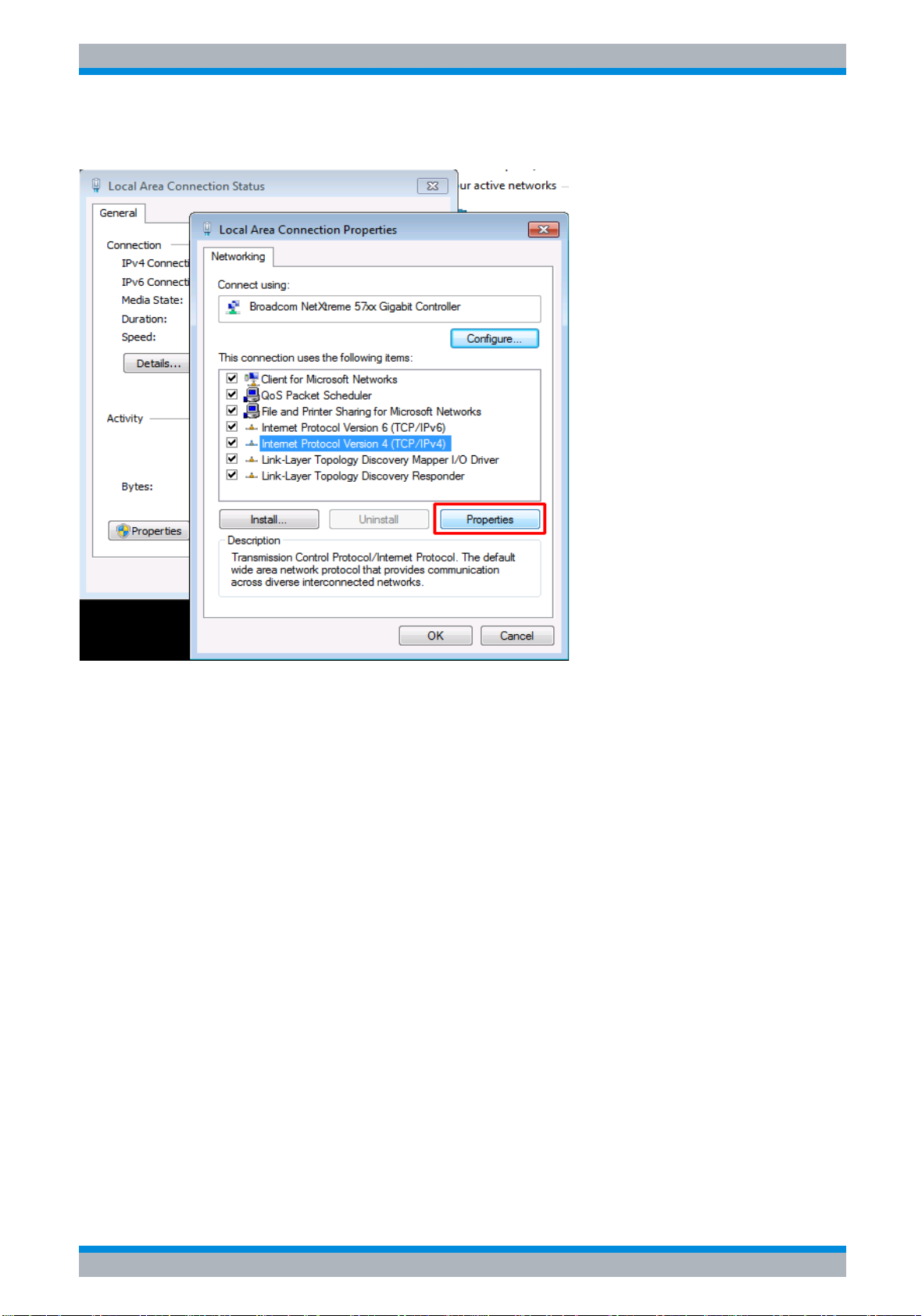
R&S ESU Preparing for Use
Configuring the LAN Interface
➢ Select the entry named Internet Protocol Version 4 (TCP/IPv4) to highlight it.
➢ Select the Properties button.
➢ On the General tab, select Use the Following DNS Server Address and enter your own DNS
addresses.
For more information refer to the Windows Help.
2.5.2.3 Installing Additional Network Protocols and Services
The procedure for installing additional network protocols and services is provided in the
chapter “ Installing Additional Network Protocols & Services” on page 6.3.
Quick Start Guide 1302.6163.62 - 05 2.31

R&S ESU Preparing for Use
Configuring the LAN Interface
2.5.3 Login
Windows requires that users identify themselves by entering a user name and password in a
login window. The instrument provides a factory-installed auto login function, i.e. login is
carried out automatically in the background. The ID used for auto login has administrator
rights.
The user name is “instrument”. The password of the latest firmware version is “894129”.
The passwords for older firmware version are:
• “123456” (FW4.4x and 4.5x)
• “instrument” (< FW4.4x)
The user name is “instrument” in all firmware versions.
Note that the default password is updated when you upgrade the firmware. However, a
downgrade of the firmware does not restore the previous passwords. Also, a password that
differs from the default one does not change when you upgrade or downgrade the firmware.
For information on how to deactivate the automatic login, refer to chapter “LAN Interface”,
section “ Deactivating the Automatic Login Mechanism” on page 6.23.
2.32 Quick Start Guide 1302.6163.62 - 05

R&S ESU Preparing for Use
Operating System Properties
2.6 Operating System Properties
The instrument contains the Microsoft Windows operating system which has been configured
according to the instrument’s features and needs. Changes in the system setup are only
required when peripherals like keyboard or a printer are installed or if the network
configuration does not comply with the default settings. After the instrument is started, the
operating system boots and the instrument firmware is started automatically.
To ensure that the instrument software functions properly, certain rules must be adhered to
concerning the operating system.
The following program packages have been tested:
The instrument is equipped with the Microsoft Window operating system. Additional
software can therefore be installed on the instrument. The use and installation of additional
software may impair instrument function. Thus, run only programs that Rohde & Schwarz
has tested for compatibility with the instrument software.
The drivers and programs used on the instrument under Microsoft Windows have been
adapted to the instrument. Existing instrument software must always be modified using only
update software released by Rohde & Schwarz.
• Symantec Endpoint Security (virus protection software)
• FileShredder (for reliable deletion of files from the harddisk)
Virus protection
Users must take appropriate steps to protect their instruments from infection. Beside the use
of strong firewall settings and regular scanning of any removable storage device used with a
Rohde & Schwarz instrument, it is also recommended that anti-virus software be installed on
the instrument. While Rohde & Schwarz does NOT recommend running anti-virus software in
the background on Windows-based instruments, due to potentially degrading instrument
performance, it does recommend running it during non-critical hours.
For details and recommendations, see the Rohde & Schwarz White Paper “Malware
Protection” available at http://www.rohde-schwarz.com/appnote/1EF73.
2.6.0.1 Windows Service Packs
Microsoft regularly creates security updates and other patches to protect systems running the
with Windows operating systems. These are released through the Microsoft Update website
and associated update server. Instruments using Windows, especially those that connect to a
network, should be updated regularly.
For details and recommendations, see the Rohde & Schwarz White Paper “Malware
Protection” available at http://www.rohde-schwarz.com/appnote/1EF73.
Quick Start Guide 1302.6163.62 - 05 2.33

R&S ESU Preparing for Use
Operating System Properties
2.6.0.2 Opening the Windows Start Menu
You can open the Windows Start menu by pressing the Windows key ( ) or the key
combination CTRL+ESC. From the start menu, you can navigate to the submenus by using
the mouse or the arrow keys. To return to the measurement screen, activate the R&S Analyzer
Interface button in the task bar.
You can also open the Windows Start menu with the OPEN START MENU softkey in the
SETUP menu.
2.34 Quick Start Guide 1302.6163.62 - 05

R&S ESU Firmware Update and Installation of Firmware Options
3 Firmware Update and Installation of
Firmware Options
3.1 Firmware Update . . . . . . . . . . . . . . . . . . . . . . . . . . . . . . . . . . 3.2
3.2 Activating Firmware Options . . . . . . . . . . . . . . . . . . . . . . . . 3.4
Quick Start Guide 1302.6163.62 - 05 3.1

R&S ESU Firmware Update and Installation of Firmware Options
Firmware Update
3.1 Firmware Update
For the latest firmware version refer to the Rohde & Schwarz internet site and download the
most up-to-date firmware.
A detailed description about performing the firmware update in the intrument is given in the
release note, provided on this CD. The release note is also downloadable from the
Rohde & Schwarz internet site.
You can install a new firmware version by copying the required file to the instrument using
USB devices (for example a memory stick), GPIB or LAN or by installing the firmware through
a remote connection in a LAN.
➢ Press the SETUP key. The SETUP menu will open.
➢ Press the NEXT key.
The side menu will open.
➢ Press the FIRMWARE UPDATE softkey.
The dialog box to install a new firmware version opens.
Example:
The firmware update files are stored on a memory stick in the Update directory. After you
insert the memory stick, it will be detected as drive E:.
In this case, the required path specification is E:\UPDATE.
➢ If you install via LAN using the Remote Desktop application, enter the drive name and
directory or press the “Browse” button to locate the directory.
➢ In the displayed dialog box, select the drive.
➢ On the selected drive, select the folder that contains the installation file (*.exe).
➢ Press the “Select” button to confirm your selection and go back to the “Firmware Update”
dialog box.
➢ Press the FIRMWARE UPDATE softkey in the submenu.
The installation program will guide you through the installation.
Do not switch the instrument off until the update process has been finished completely.
IEC bus command: "SYST:FIRM:UPD 'E:\UPDATE'"
After a firmware update, the R&S ESU requires a self alignment (“UNCAL” status message).
For details, refer to the Operating Manual.
➢ To restore the previous firmware version, press the RESTORE FIRMWARE softkey.
IEC bus command: --
3.2 Quick Start Guide 1302.6163.62 - 05

R&S ESU Firmware Update and Installation of Firmware Options
Firmware Update
Performing a remote installation from a Windows PC
This method requires a LAN connection from the instrument to a Windows PC.
➢ Run the installation file (*.exe) on your PC.
➢ Select “Remote Installation” and click the “Next” button.
➢ Select the packages you would like to install and click the “Next” button.
➢ Your LAN subnet is scanned and a list of all instruments in the network is compiled.
Note: To communicate with the instrument, the installer must pass a possible firewall.
Therefore, add the executable to your firewall rules.
➢ Select the instruments you would like to update. You can select up to five instruments to
update at the same time.
Note: All instruments in your LAN structure are added to the list. Make sure that you select
the correct instruments.
➢ To display further options, click the “Options” button.
➢ Start the installation by clicking “Install”.
➢ Confirm that you want to reboot the instrument in order to activate the firmware update. The
instrument restarts automatically.
Quick Start Guide 1302.6163.62 - 05 3.3

R&S ESU Firmware Update and Installation of Firmware Options
Activating Firmware Options
3.2 Activating Firmware Options
Firmware options are enabled by entering license keys via the following operating sequence:
➢ Press the SETUP key.
The SETUP menu will open.
➢ Press the GENERAL SETUP softkey.
➢ Press the OPTIONS softkey.
The OPTIONS menu will open. Options already available are listed in a table that is
displayed when the submenu is opened.
➢ Press the INSTALL OPTION softkey.
The field for entering the license key for the firmware option now appears.
After you enter a valid license key, OPTION KEY OK will appear in the message line and
the option will be entered in the FIRMWARE OPTIONS table.
If you enter an invalid license key, the message OPTION KEY INVALID will appear in the
message line.
➢ The REMOVE OPTION softkey deletes all existing firmware options. To prevent
unintentional deletion, the system asks you to confirm that you really want to perform this
operation.
3.4 Quick Start Guide 1302.6163.62 - 05

R&S ESU Basic Operation
4 Basic Operation
4.1 Diagram Layout . . . . . . . . . . . . . . . . . . . . . . . . . . . . . . . . . . . 4.2
4.1.1 Displays in the Diagram Area . . . . . . . . . . . . . . . . . . . . . 4.3
4.2 Setting Parameters . . . . . . . . . . . . . . . . . . . . . . . . . . . . . . . . 4.7
4.2.1 The Keypad . . . . . . . . . . . . . . . . . . . . . . . . . . . . . . . . . . . 4.7
4.2.2 The Rotary Knob and Arrow Keys . . . . . . . . . . . . . . . . . . 4.8
4.2.3 Editing Numeric Parameters . . . . . . . . . . . . . . . . . . . . . . 4.8
4.2.4 Editing Alphanumeric Parameters . . . . . . . . . . . . . . . . . . 4.9
4.2.4.1 Alphanumeric Editor Type 1: . . . . . . . . . . . . . . . . . . . 4.9
4.2.4.2 Alphanumeric Editor Type 2: . . . . . . . . . . . . . . . . . . 4.10
Quick Start Guide 1302.6163.62 - 05 4.1

R&S ESU Basic Operation
Diagram Layout
4.1 Diagram Layout
Status
information
Trace information
Level axis labelling
Logo
title/date
Hardware
settings
Marker/Delta
Marker/Delta
marker
marker
Frequency axis labelling
Fig. 4-1 Screen layout of the R&S ESU during analyzer operation
Dirty flag
Enhancement
labels
4.2 Quick Start Guide 1302.6163.62 - 05

R&S ESU Basic Operation
Diagram Layout
4.1.1 Displays in the Diagram Area
Hardware settings
Ref Display of the reference level.
Offset Display of the reference level offset.
Att Display of the RF attenuation that has been set.
RBW Display of the resolution bandwidth that has been set.
If the bandwidth does not correspond to the value for automatic coupling, a green
asterisk "*" will appear in front of the field.
MT Indication of the measurement time
PREAMP Indication of the preamplifier status
VBW Display of the video bandwidth that has been set.
If the bandwidth does not correspond to the value for automatic coupling, a green
asterisk "*" will appear in front of the field.
SWT Display of the sweep time that has been set (SWEEP TIME).
If the sweep time does not correspond to the value for automatic coupling, an
asterisk "*" will appear in front of the field. The color of the asterisk will turn to red if
the sweep time is set below the value for automatic coupling. In this case, the sweep
time must be increased.
Marker /
Delta
LIMIT
CHECK
Contains the x and y axis positions of the last marker or delta marker that was set
as well as its index. The value in the square brackets after the index indicates the
trace to which the marker is assigned as well as the active measurement function.
The measurement functions of the markers are indicated with the following
abbreviations:
• FXD Reference fixed marker active
• PHN Phase noise measurement active
• CNT Frequency counter active
• TRK Signal track active
• NOI Noise measurement active
• MOD Measurement of the AM modulation depth active
• TOI measurement active
Display of the results of the limit check.
Quick Start Guide 1302.6163.62 - 05 4.3

R&S ESU Basic Operation
Diagram Layout
Status displays
The status displays on the left side of the diagram indicate any irregularities (e.g. UNCAL).
UNCAL Indicates that one of the following conditions is present:
• Correction data has been switched off (CAL menu, CAL CORR OFF).
– Switch on the correction CAL CORR ON or PRESET.
• No valid correction values are available. This occurs, for example, if a firmware
update is performed followed by a cold start of the instrument.
– Record the correction data (CAL menu, CAL TOTAL).
OVLD Indicates an overload of the input mixer.
– Increase the RF attenuation.
IFOVL Indicates an overload of the IF signal path after the input mixer.
– Increase the reference level.
LOUNL Indicates that an error was detected in the instrument's frequency processing
hardware.
EXREF Is displayed if the instrument was set to an external reference but no signal was
detected on the reference input.
OVEN Indicates that the OCXO reference frequency (option R&S FSU-B4) has not yet
reached its operating temperature. The message usually disappears a few minutes
after power-on.
OVTRC Indicates a temporary overload condition of the input mixer or IF signal path while
the trace is measured with Max Hold, Min Hold or Average (Overload Trace). OVLD
and IFOVL override this indication.
4.4 Quick Start Guide 1302.6163.62 - 05

R&S ESU Basic Operation
Diagram Layout
Trace information
Trace #
Trace number
Trace
number
Detector
auto /
manual
1 PK *
CLRWR
1-3
Detector
Selected detector:
• AP: AUTOPEAK detector
• PK: MAX PEAK detector
• MI: MIN PEAK detector
Trace
mathematics
Trace mode
• SA: SAMPLE detector
• AV: AVERAGE detector
• RM: RMS detector
• QP: QUASIPEAK detector
auto / manual
The selected detector does not match the one for automatic
coupling.
Trace Mode
Display of the sweep mode:
• CLRWR: CLEAR/WRITE
• MAXH: MAX HOLD
• MINH: MIN HOLD
• AVG: AVERAGE
• VIEW: VIEW
Trace Mathematics
Indicates that the trace difference function is activated, e.g. 1-3
in the example means that trace 3 is subtracted from trace 1.
Quick Start Guide 1302.6163.62 - 05 4.5

R&S ESU Basic Operation
Diagram Layout
Enhancement labels:
The enhancement labels on the right-hand side of the measurement diagram indicate that the
user chose instrument settings that affect the measurement results even though this is not
immediately apparent from the display of the measured values.
* (star) The current instrument setting does not match the one during which the displayed
traces were recorded. This occurs in the following cases:
– The instrument setting is changed while a measurement is in progress.
– The instrument setting is changed in the SINGLE SWEEP mode after the end
of the sweep, and a new sweep is not started.
– The instrument setting is changed after a trace has been set to VIEW.
The display remains on screen until the user eliminates the cause. In some
cases, this involves starting a new sweep (SINGLE SWEEP mode) or switching
the affected trace to BLANK.
A/B Designation for screen A/B. If screen A/B is activated for entering measurement
parameters, the label background will be in color.
SGL The sweep is set to SINGLE SWEEP.
GAT The frequency sweep is controlled via the EXT TRIG/GATE connector.
TRG Instrument triggering is not free running (≠ FREE RUN).
LVL A level offset ≠ 0 dB is set.
FRQ A frequency offset ≠ 0 Hz is set.
TDF A TRANSDUCER FACTOR is activated.
TDS A TRANSDUCER SET is activated.
PRN Printer output is active.
75 Ω The input impedance of the instrument is set to 75 Ω.
EXT The instrument is configured for operation with an external reference.
PA The RF PREAMPLIFIER is switched on (option R&S ESU-B24).
PS The PRESELECTOR is switched on.
3DB Gauss Filter (3 dB)
6DB EMI Filter (6 dB)
FFT FFT Filter
CHN Channel Filter
RRC RRC Filter
AC IN The measurement is outside the valid frequency range.
4.6 Quick Start Guide 1302.6163.62 - 05

R&S ESU Basic Operation
Setting Parameters
4.2 Setting Parameters
4.2.1 The Keypad
The keypad is used to enter numeric parameters. It contains the following keys:
• Numeric keys 0...9
• Decimal point
Inserts a decimal point "." at the cursor position.
• Sign key
Changes the sign of a numeric parameter.
In the case of an alphanumeric parameter, inserts a "-" at the cursor position.
• Unit keys (GHz/-dBm MHz/dBm, kHz/dB and Hz/dB)
These keys add the selected unit to the entered numeric value and complete the entry.
In the case of level entries (e.g. in dB) or dimensionless values, all units have the value "1"
as multiplying factor. Thus, they have the same function as an ENTER key. The same is
true for an alphanumeric entry.
In addition, the unit keys open and close selection fields in tables (subtables).
• BACK key
– If a numeric entry has already been started, this key deletes the character to the left of
the cursor.
– If an entry has been completed or not yet started, this key toggles between the currently
and previously valid value (UNDO function).
• ESC/CANCEL key
– Closes the entry field if an entry has been started or has not yet been made. The original
value is retained.
– Closes the entry field if an entry has been completed.
– Closes the System Messages dialog box.
Quick Start Guide 1302.6163.62 - 05 4.7

R&S ESU Basic Operation
Setting Parameters
• ENTER key
– Concludes dimensionless entries. The new value is accepted.
With frequency entries, the ENTER key corresponds to the Hz key.
With time data, it corresponds to the µs (kHz) key.
4.2.2 The Rotary Knob and Arrow Keys
The rotary knob and arrow keys are located next to the keypad.
The rotary knob has several functions:
• Increments (clockwise direction) or decrements (counterclockwise
direction) the instrument parameter at a defined step width in the case
of a numeric entry.
• Shifts the selection bar horizontally or vertically within tables as long as
an entry field is not open. The arrow keys are used to change the
direction of motion (horizontal/vertical).
• Selects the individual letters when the alphanumeric editor is used.
• Shifts markers, limit lines, etc. on the screen.
• When it is pressed, it concludes an entry.
Within a table, the arrow keys move the selection bar to the desired
position.
Within the alphanumeric editor, the Ul or Ur arrow keys move the cursor
to the desired position.
The Uu or Ud arrow keys do the following:
• Increase or decrease the instrument parameter in the case of numeric
entries.
• Switch between the editing line and the character selection in the case
of alphanumeric entries.
4.2.3 Editing Numeric Parameters
Numeric values are always entered in a data entry field that automatically appears after the
parameter is selected.
Title line with parameter designation
Editing line with parameter value and unit
Status and error messages
The title line shows the name of the instrument parameter that was selected. The entry is
performed in the editing line. After the entry field is opened, it will contain the currently valid
parameter value and its unit. The optional third and fourth lines show status and error
messages which always refer to the current entry.
4.8 Quick Start Guide 1302.6163.62 - 05

R&S ESU Basic Operation
Setting Parameters
4.2.4 Editing Alphanumeric Parameters
If an external keyboard is not available, the character selection field is automatically opened
for entering alphanumeric parameters. Two models of the alphanumeric editor are available.
4.2.4.1 Alphanumeric Editor Type 1:
Entry (editing) line
Message line
Character selection line
The Uu or Ud arrow keys switch between the editing line and the character selection field.
Entering the text
➢ Select the parameter.
Data entry is automatically activated after the data entry field is opened. The cursor is now
located at the start of the previous entry in the editing line.
➢ Using the Ud arrow key, place the cursor in the character selection field.
The cursor now marks the first letter of the editor.
➢ Using the Ul and Ur arrow keys or the rotary knob, place the cursor on the character that
you want to enter in the editing line.
➢ Press either the ENTER key or the rotary knob.
The character will be added to the editing line.
Correcting the entry
➢ Using the Uu arrow key, place the cursor in the editing line.
➢ Using the Ul and Ur arrow keys or the rotary knob, place the cursor after the character you
want to delete.
➢ Press the BACK key.
The entry to the left of the cursor will be deleted.
Correcting the entry
➢ Using the Uu key, place the cursor in the editing line.
➢ Press one of the unit keys or the rotary knob.
The data entry field will close, and the new entry will be accepted by the instrument.
Cancelling the entry
➢ Press the ESC key.
The data entry field will close, and the previous entry will be retained.
Quick Start Guide 1302.6163.62 - 05 4.9

R&S ESU Basic Operation
Setting Parameters
4.2.4.2 Alphanumeric Editor Type 2:
The entry area consists of two parts:
• The editing line
• The character selection field
The Uu or arrow keys switch between the editing line and the character selection field.
Entering the text
➢ Select a parameter.
Data entry is automatically activated after the data entry field is opened. In tables, the
character selection field is accessed by using the Ud arrow key.
The cursor is now located at the start of the existing entry in the editing line.
➢ Using the Ud arrow key, place the cursor in the character selection field.
The cursor now marks the first character of the editor.
➢ Using the Ul and Ur arrow keys or the rotary knob, place the cursor on the character that
you want to enter in the editing line.
➢ Press the ENTER key or the rotary knob.
The character will be added to the editing line.
Correcting the entry (alternative 1)
➢ Using the rotary knob, go to the << character in the character selection field.
➢ By pressing the rotary knob on << and >>, place the cursor after the character you want to
delete.
➢ Using the rotary knob, select the BACK field and press the rotary knob.
The entry to the left of the cursor in the editing line will be deleted.
Correcting the entry (alternative 2)
➢ Using the Uu arrow key, place the cursor in the editing line.
➢ Using the Ul and Ur arrow keys or the rotary knob, place the cursor after the character you
want to delete.
➢ Press the BACK key.
The entry to the left of the cursor will be deleted.
4.10 Quick Start Guide 1302.6163.62 - 05

R&S ESU Basic Operation
Setting Parameters
Completing the entry (alternative 1)
➢ Using the rotary knob, select the EXIT field and then press the rotary knob.
The data entry field will close, and the new entry will be accepted by the instrument.
Completing the entry (alternative 2)
➢ Using the Uu arrow key, place the cursor by the editing line.
➢ Press one of the unit keys or the rotary knob.
The data entry field will close, and the new entry will be accepted by the instrument.
Cancelling the entry
➢ Press the ESC key.
The data entry field will close, and the previous entry will be retained.
Quick Start Guide 1302.6163.62 - 05 4.11

R&S ESU Basic Operation
Setting Parameters
4.12 Quick Start Guide 1302.6163.62 - 05

R&S ESU Basic Measurement Examples
5 Basic Measurement Examples
5.1 Introduction . . . . . . . . . . . . . . . . . . . . . . . . . . . . . . . . . . . . . . 5.3
5.2 Performing a Level and Frequency Measurement . . . . . . . 5.4
5.3 Measuring a Sinusoidal Signal . . . . . . . . . . . . . . . . . . . . . 5.16
5.3.1 Measuring the Level and Frequency with Markers . . . . 5.16
5.3.1.1 Procedure . . . . . . . . . . . . . . . . . . . . . . . . . . . . . . . . 5.16
5.3.1.2 Increasing the Frequency Resolution . . . . . . . . . . . 5.17
5.3.1.3 Setting the Reference Level . . . . . . . . . . . . . . . . . . 5.18
5.3.2 Measuring the Signal Frequency using the Frequency
Counter . . . . . . . . . . . . . . . . . . . . . . . . . . . . . . . . . . . . . . . . . . 5.19
5.4 Measuring Harmonics of Sinusoidal Signals . . . . . . . . . . 5.21
5.4.1 Measuring the Suppression of the First and Second
Harmonic of an Input Signal . . . . . . . . . . . . . . . . . . . . . . . . . . 5.21
5.4.2 Reducing Noise . . . . . . . . . . . . . . . . . . . . . . . . . . . . . . . 5.23
5.5 Measuring Harmonics with Frequency Sweeps . . . . . . . . 5.25
5.5.1 High-Sensitivity Harmonics Measurements . . . . . . . . . . 5.25
5.6 Measuring Signal Spectra with Multiple Signals . . . . . . . 5.28
5.6.1 Separating Signals by Selecting the Resolution
Bandwidth . . . . . . . . . . . . . . . . . . . . . . . . . . . . . . . . . . . . . . . . 5.28
5.6.1.1 Separating Two Signals with a Level of –30 dBm
each at a Frequency Spacing of 30 kHz . . . . . . . . . . . . . . . 5.28
5.6.1.2 Measuring the Modulation Depth of an
AM-Modulated Carrier in the Frequency Domain . . . . . . . . 5.34
5.7 Storing and Loading Instrument Settings . . . . . . . . . . . . 5.36
Quick Start Guide 1302.6163.62 - 05 5.1

R&S ESU Basic Measurement Examples
5.7.1 Storing an Instrument Configuration (without Traces) . . 5.36
5.7.1.1 Storing Traces . . . . . . . . . . . . . . . . . . . . . . . . . . . . . 5.37
5.7.2 Loading an Instrument Configuration . . . . . . . . . . . . . . . 5.38
5.7.2.1 Automatic Loading of a Data Record during
Booting . . . . . . . . . . . . . . . . . . . . . . . . . . . . . . . . . . . . . . . . . 5.39
5.8 Printing Out the Measurement Results . . . . . . . . . . . . . . . 5.40
5.8.1 Selecting the Color Setting for the Printout . . . . . . . . . . 5.40
5.9 Additional Measurement Examples . . . . . . . . . . . . . . . . . . 5.41
This chapter provides a brief introduction to operating the R&S ESU EMI Test Receiver. A
more detailed discussion of the basic operating steps, e.g. selecting menus and setting
parameters, plus measurement examples are provided in the Operating Manual, chapters 2
and 4.
• analyzer measurements
– “ Measuring a Sinusoidal Signal” on page 5.16
– “ Measuring Harmonics of Sinusoidal Signals” on page 5.21
– “ Measuring Harmonics with Frequency Sweeps” on page 5.25
– “ Measuring Signal Spectra with Multiple Signals” on page 5.28
– “ Storing and Loading Instrument Settings” on page 5.36
– “ Printing Out the Measurement Results” on page 5.40
– “ Additional Measurement Examples” on page 5.41
5.2 Quick Start Guide 1302.6163.62 - 05
R&S ESU Basic Measurement Examples
Introduction
5.1 Introduction
This section describes a typical and simple measurement task for an EMI test receiver. Each
operating step is explained with the aid of R&S ESU for rapid familiarization of the user without
the need to know all the details of the operating functions.
In the introductory example a standard measurement of level and frequency is performed with
the aid of the SCAN TABLE. This measurement is an overview and pre-certification
measurement to be performed before the final standard-conformal measurement is carried
out. Each operating step is explained with the aid of R&S ESU for rapid familiarization of the
user without the need to know all the details of the operating functions.
If unknown (RFI) signals are to be measured, it is strongly
recommended to provide for at least 10 dB RF attenuation at the RF
input in order to protect the input circuit.
In the following example, the R&S ESU is set to default values in the receiver mode. The
default setup is activated by pressing first the RECEIVER hotkey and then the PRESET key.
The main default parameters in receiver mode are listed in the following table:
Parameter Setting
Receiver frequency 100 MHz
RF attenuation Auto
Preamplifier Off
Detector AV
Measurement time 100 ms
RES bandwidth 120 kHz
Demodulator Off
Trigger Free run
Quick Start Guide 1302.6163.62 - 05 5.3

R&S ESU Basic Measurement Examples
Performing a Level and Frequency Measurement
5.2 Performing a Level and Frequency Measurement
Measurement
Measurement and display of RFI signal levels versus frequency is one of the most frequent
tasks performed by an EMI Test Receiver. In the case of unknown signals, PRESET values
will mostly be used for the measurement. If levels higher than +137 dBµV (10 dB
RF attenuation) are expected or possible, a power attenuator has to be connected in front of
the EMI Test Receiver input. Very high levels may otherwise damage or destroy the attenuator
or input mixer.
Main Test Receiver Functions
The main functions required for the level and frequency measurement are setting the SCAN
TABLE (START FREQUENCY, STOP FREQUENCY, STEPSIZE), selecting the resolution
(IF) bandwidth (RES BW), setting the measurement time (MEAS TIME) and selecting the
detectors (e.g. peak or average) and MARKER functions required for the analysis.
Measurement Sequence - Level and Frequency Measurement
In this example, the spectrum of the signal present at RF INPUT is recorded in the frequency
range 150 kHz to 30 MHz. The SCAN TABLE and associated parameters are manually set.
The example is generally suitable for all fast pre-compliance measurements required for
measuring unknown noise spectra of DUTs in the development stage and for modifying
prototypes and can be used as a basis for final tests later on.
The high speed of fully synthesized scans, the frequency and amplitude accuracy and the
wide dynamic range of the R&S ESU EMI Test Receiver are of utmost importance and very
useful for these measurements.
Short form
1. Reset the instrument.
2. Select the receiver mode.
3. Program a SCAN TABLE.
4. Select the detectors.
5. Apply the signal.
6. Start the scan.
7. Analyze the level in frequency domain.
– Analyze the level in frequency domain using the marker functions.
– Analyze the level in frequency domain using the peak search functions.
8. Set the SPLIT SCREEN function.
9. Tune the receiver frequency and obtain final test results using the QUASIPEAK detector.
10.From overview to standard-conformal measurement
5.4 Quick Start Guide 1302.6163.62 - 05
 Loading...