


R&S®FSMR3000
Measuring Receiver
User Manual
(;Ý1@2)
1179011602
Version 03

This document describes the following R&S®FSMR3000 models:
●
R&S®FSMR3008 (1345.4004K08)
●
R&S®FSMR3026 (1345.4004K26)
●
R&S®FSMR3050 (1345.4004K50)
The contents of this manual correspond to firmware version 1.10 and higher.
© 2022 Rohde & Schwarz GmbH & Co. KG
Mühldorfstr. 15, 81671 München, Germany
Phone: +49 89 41 29 - 0
Fax: +49 89 41 29 12 164
Email: info@rohde-schwarz.com
Internet: www.rohde-schwarz.com
Subject to change – Data without tolerance limits is not binding.
R&S® is a registered trademark of Rohde & Schwarz GmbH & Co. KG.
Trade names are trademarks of their owners.
1179.0116.02 | Version 03 | R&S®FSMR3000
Throughout this manual, products from Rohde & Schwarz are indicated without the ® symbol , e.g. R&S®FSMR3000 is indicated as
R&S FSMR3000.

R&S®FSMR3000
1 Safety and regulatory information........................................................5
2 Documentation overview.......................................................................9
3 Welcome to the R&S FSMR3...............................................................11
4 Getting started......................................................................................12
5 Applications..........................................................................................85
6 Measurements and results..................................................................95
7 Common measurement settings.......................................................112
8 Common analysis and display functions........................................ 180
Contents
Contents
9 Data management.............................................................................. 236
10 General instrument setup..................................................................268
11 Network operation and remote control............................................ 318
12 Remote commands............................................................................386
13 Troubleshooting.................................................................................689
14 Transporting.......................................................................................697
15 Maintenance, storage, transport and disposal................................698
List of commands.............................................................................. 700
Index....................................................................................................716
3User Manual 1179.0116.02 ─ 03

R&S®FSMR3000
Contents
4User Manual 1179.0116.02 ─ 03

R&S®FSMR3000
1 Safety and regulatory information
Safety and regulatory information
Safety instructions
The product documentation helps you use the product safely and efficiently. Follow the
instructions provided here and in the following chapters.
Intended use
The product is intended for the development, production and verification of electronic
components and devices in industrial, administrative, and laboratory environments.
Use the product only for its designated purpose. Observe the operating conditions and
performance limits stated in the data sheet.
Where do I find safety information?
Safety information is part of the product documentation. It warns you of potential dangers and gives instructions on how to prevent personal injury or damage caused by
dangerous situations. Safety information is provided as follows:
●
In Chapter 1.1, "Safety instructions", on page 5. The same information is provided in many languages as printed "Safety Instructions". The printed "Safety
Instructions" are delivered with the product.
●
Throughout the documentation, safety instructions are provided when you need to
take care during setup or operation.
1.1 Safety instructions
Products from the Rohde & Schwarz group of companies are manufactured according
to the highest technical standards. To use the products safely, follow the instructions
provided here and in the product documentation. Keep the product documentation
nearby and offer it to other users.
Use the product only for its intended use and within its performance limits. Intended
use and limits are described in the product documentation such as the data sheet,
manuals and the printed "Safety Instructions". If you are unsure about the appropriate
use, contact Rohde & Schwarz customer service.
Using the product requires specialists or specially trained personnel. These users also
need sound knowledge of at least one of the languages in which the user interfaces
and the product documentation are available.
Never open the casing of the product. Only service personnel authorized by
Rohde & Schwarz are allowed to repair the product. If any part of the product is damaged or broken, stop using the product. Contact Rohde & Schwarz customer service at
http://www.customersupport.rohde-schwarz.com.
Lifting and carrying the product
The product is heavy. Do not move or carry the product by yourself. A single person
can only carry a maximum of 18 kg safely depending on age, gender and physical condition. Look up the maximum weight in the data sheet. Use the product handles to
5User Manual 1179.0116.02 ─ 03

R&S®FSMR3000
Safety and regulatory information
Safety instructions
move or carry the product. Do not lift by the accessories mounted on the product.
Accessories are not designed to carry the weight of the product.
To move the product safely, you can use lifting or transporting equipment such as lift
trucks and forklifts. Follow the instructions provided by the equipment manufacturer.
Choosing the operating site
Only use the product indoors. The product casing is not waterproof. Water that enters
can electrically connect the casing with live parts, which can lead to electric shock,
serious personal injury or death if you touch the casing. If Rohde & Schwarz provides
accessories designed for your product, e.g. a carrying bag, you can use the product
outdoors.
Unless otherwise specified, you can operate the product up to an altitude of 2000 m
above sea level. The product is suitable for pollution degree 2 environments where
nonconductive contamination can occur. For more information on environmental conditions such as ambient temperature and humidity, see the data sheet.
Setting up the product
Always place the product on a stable, flat and level surface with the bottom of the product facing down. If the product is designed for different positions, secure the product so
that it cannot fall over.
If the product has foldable feet, always fold the feet completely in or out to ensure stability. The feet can collapse if they are not folded out completely or if the product is
moved without lifting it. The foldable feet are designed to carry the weight of the product, but not an extra load.
If stacking is possible, keep in mind that a stack of products can fall over and cause
injury.
If you mount products in a rack, ensure that the rack has sufficient load capacity and
stability. Observe the specifications of the rack manufacturer. Always install the products from the bottom shelf to the top shelf so that the rack stands securely. Secure the
product so that it cannot fall off the rack.
Connecting to power
The product is an overvoltage category II product. Connect the product to a fixed
installation used to supply energy-consuming equipment such as household appliances and similar loads. Keep in mind that electrically powered products have risks, such
as electric shock, fire, personal injury or even death.
Take the following measures for your safety:
●
Before switching on the product, ensure that the voltage and frequency indicated
on the product match the available power source. If the power adapter does not
adjust automatically, set the correct value and check the rating of the fuse.
●
Only use the power cable delivered with the product. It complies with country-specific safety requirements. Only insert the plug into an outlet with protective conductor terminal.
6User Manual 1179.0116.02 ─ 03
R&S®FSMR3000
Safety and regulatory information
Safety instructions
●
Only use intact cables and route them carefully so that they cannot be damaged.
Check the power cables regularly to ensure that they are undamaged. Also ensure
that nobody can trip over loose cables.
●
If the product needs an external power supply, use the power supply that is delivered with the product or that is recommended in the product documentation or a
power supply that conforms to the country-specific regulations.
●
Only connect the product to a power source with a fuse protection of maximum
20 A.
●
Ensure that you can disconnect the product from the power source at any time.
Pull the power plug to disconnect the product. The power plug must be easily
accessible. If the product is integrated into a system that does not meet these
requirements, provide an easily accessible circuit breaker at the system level.
Using headphones
Take the following measures to prevent hearing damage. Before using headphones,
check the volume and reduce it if necessary. If you monitor varying signal levels, take
off the headphones and wait until the signal has settled. Then adjust the volume.
Cleaning the product
Use a dry, lint-free cloth to clean the product. When cleaning, keep in mind that the
casing is not waterproof. Do not use liquid cleaning agents.
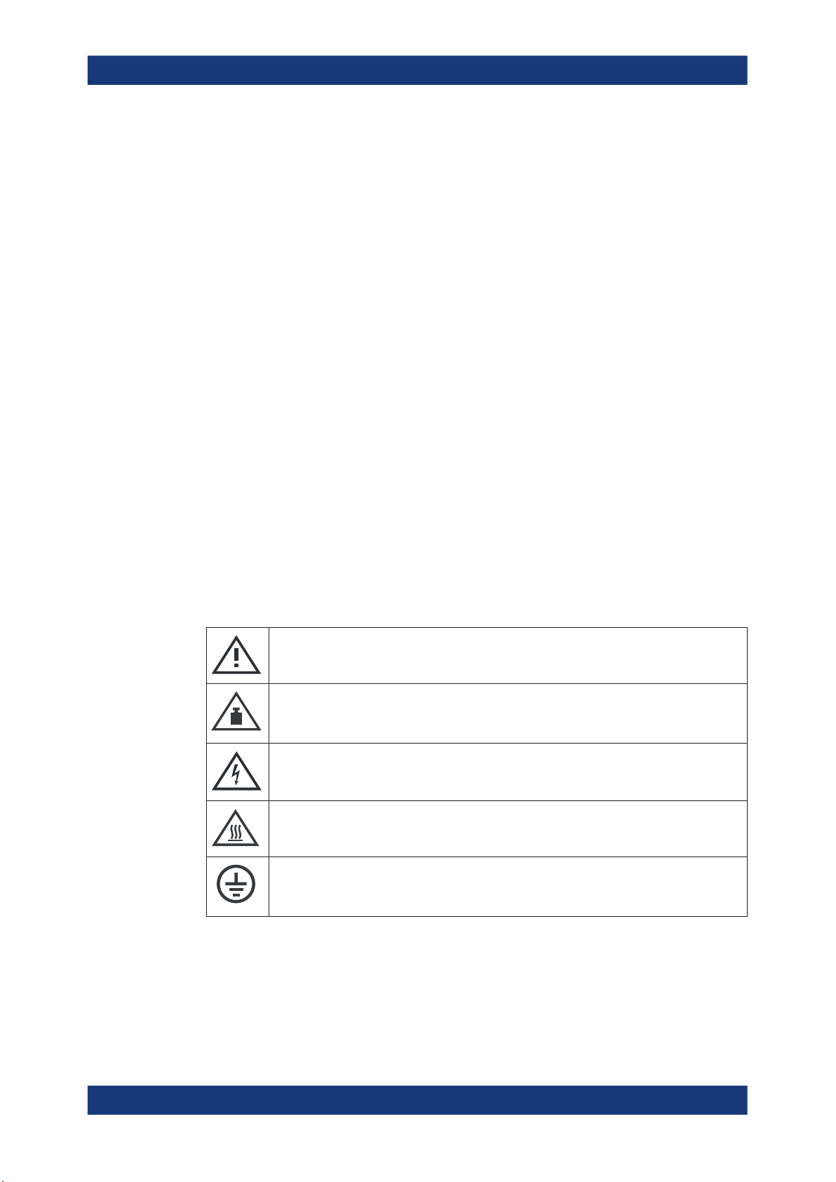
Meaning of safety labels
Safety labels on the product warn against potential hazards.
Potential hazard
Read the product documentation to avoid personal injury or product damage.
Heavy product
Be careful when lifting, moving or carrying the product. Carrying the product requires a suffi-
cient number of persons or transport equipment.
Electrical hazard
Indicates live parts. Risk of electric shock, fire, personal injury or even death.
Hot surface
Do not touch. Risk of skin burns. Risk of fire.
Protective conductor terminal
Connect this terminal to a grounded external conductor or to protective ground. This connec-
tion protects you against electric shock if an electric problem occurs.
7User Manual 1179.0116.02 ─ 03

R&S®FSMR3000
1.2 Warning messages in the documentation
Safety and regulatory information
Korea certification class B
A warning message points out a risk or danger that you need to be aware of. The signal word indicates the severity of the safety hazard and how likely it will occur if you do
not follow the safety precautions.
WARNING
Potentially hazardous situation. Could result in death or serious injury if not avoided.
CAUTION
Potentially hazardous situation. Could result in minor or moderate injury if not avoided.
NOTICE
Potential risks of damage. Could result in damage to the supported product or to other
property.
1.3 Korea certification class B
이 기기는 가정용(B급) 전자파 적합기기로서 주로 가정에서 사용하는 것을 목적으로 하
며, 모든 지역에서 사용할 수 있습니다.
8User Manual 1179.0116.02 ─ 03

R&S®FSMR3000
2 Documentation overview
2.1 Getting started manual
Documentation overview
Service manual
This section provides an overview of the R&S FSMR3 user documentation. Unless
specified otherwise, you find the documents on the R&S FSMR3 product page at:
www.rohde-schwarz.com/product/FSMR3000.html/
Introduces the R&S FSMR3 and describes how to set up and start working with the
product. Includes basic operations, typical measurement examples, and general information, e.g. safety instructions, etc.
A printed version is delivered with the instrument. A PDF version is available for download on the Internet.
2.2 User manuals and help
Separate user manuals are provided for the base unit and the firmware applications:
●
Base unit manual
Contains the description of all instrument modes and functions. It also provides an
introduction to remote control, a complete description of the remote control commands with programming examples, and information on maintenance, instrument
interfaces and error messages.
●
Firmware application manual
Contains the description of the specific functions of a firmware application, including remote control commands. Basic information on operating the R&S FSMR3 is
not included.
The contents of the user manuals are available as help in the R&S FSMR3. The help
offers quick, context-sensitive access to the complete information for the base unit and
the firmware applications.
All user manuals are also available for download or for immediate display on the Internet.
2.3 Service manual
Describes the performance test for checking the rated specifications, module replacement and repair, firmware update, troubleshooting and fault elimination, and contains
mechanical drawings and spare part lists.
The service manual is available for registered users on the global Rohde & Schwarz
information system (GLORIS):
9User Manual 1179.0116.02 ─ 03

R&S®FSMR3000
2.4 Instrument security procedures
2.5 Printed safety instructions
2.6 Data sheets and brochures
Documentation overview
Application notes, application cards, white papers, etc.
Deals with security issues when working with the R&S FSMR3 in secure areas. It is
available for download on the Internet.
Provides safety information in many languages. The printed document is delivered with
the product.
The data sheet contains the technical specifications of the R&S FSMR3. It also lists the
firmware applications and their order numbers, and optional accessories.
The brochure provides an overview of the instrument and deals with the specific characteristics.
See www.rohde-schwarz.com/brochure-datasheet/FSMR3000/
2.7 Release notes and open-source acknowledgment (OSA)
The release notes list new features, improvements and known issues of the current
firmware version, and describe the firmware installation.
The open-source acknowledgment document provides verbatim license texts of the
used open source software.
See www.rohde-schwarz.com/firmware/FSMR3000/
2.8 Application notes, application cards, white papers, etc.
These documents deal with special applications or background information on particular topics.
See www.rohde-schwarz.com/application/FSMR3000/
10User Manual 1179.0116.02 ─ 03

R&S®FSMR3000
3 Welcome to the R&S FSMR3
Welcome to the R&S FSMR3
The R&S FSMR3 is a new high-performance Rohde & Schwarz measuring receiver
developed to meet demanding customer requirements. Offering low phase noise, wide
analysis bandwidth and straightforward and intuitive operation, the measuring receiver
makes measurements fast and easy.
This user manual contains a description of the functionality that the instrument provides, including remote control operation. The latest version is available for download
at the product homepage (http://www.rohde-schwarz.com/product/FSMR3000.html).
11User Manual 1179.0116.02 ─ 03

R&S®FSMR3000
4 Getting started
4.1 Key features
Getting started
Preparing for use
The R&S FSMR3 measuring receiver is a complete solution for calibration and performance checks of signal generators and fixed or adjustable attenuators. The
R&S FSMR3 combines the functionality of multiple instruments such as a level calibrator, modulation analyzer and frequency counter in one. It is capable of calibrating all
vital parameters of a signal generator. The R&S FSMR3 provides the following outstanding key features:
●
Frequency range from 2 Hz to 8/26.5/50 GHz
●
Highly accurate level calibrator with wide level measurement range
●
Power meter with integrated support of R&S NRP-Zxx power sensors
●
Power sensor with power splitters for simplified measurement process
●
Tuned RF Level (TRFL) calibration and power measurements
●
AM/FM/PM modulation analysis
●
Easy and intuitive to operate via the large touchscreen user interface and optimized user guidance
●
SCPI recorder simplifies code generation
For a detailed specification refer to the data sheet.
4.2 Preparing for use
Here, you can find basic information about setting up the product for the first time.
● Lifting and carrying..................................................................................................13
● Unpacking and checking.........................................................................................13
● Choosing the operating site.................................................................................... 13
● Setting up the product.............................................................................................13
● Connecting the AC power....................................................................................... 15
● Switching the instrument on and off........................................................................16
● Connecting to LAN..................................................................................................17
● Connecting a keyboard........................................................................................... 18
● Connecting an external monitor.............................................................................. 18
● Windows operating system..................................................................................... 19
● Logging on.............................................................................................................. 21
● Checking the supplied options................................................................................ 23
● Performing a self-alignment.................................................................................... 23
● Considerations for test setup.................................................................................. 24
12User Manual 1179.0116.02 ─ 03

R&S®FSMR3000
4.2.1 Lifting and carrying
4.2.2 Unpacking and checking
Getting started
Preparing for use
The carrying handles are designed to lift or carry the instrument. Do not apply excessive external force to the handles.
See "Lifting and carrying the product" on page 5.
1. Unpack the R&S FSMR3 carefully.
2. Retain the original packing material. Use it when transporting or shipping the
R&S FSMR3 later.
3. Using the delivery notes, check the equipment for completeness.
4. Check the equipment for damage.
If the delivery is incomplete or equipment is damaged, contact Rohde & Schwarz.
4.2.3 Choosing the operating site
Specific operating conditions ensure proper operation and avoid damage to the product and connected devices. For information on environmental conditions such as ambient temperature and humidity, see the data sheet.
See also "Choosing the operating site" on page 6.
Electromagnetic compatibility classes
The electromagnetic compatibility (EMC) class indicates where you can operate the
product. The EMC class of the product is given in the data sheet.
●
Class B equipment is suitable for use in:
– Residential environments
– Environments that are directly connected to a low-voltage supply network that
supplies residential buildings
●
Class A equipment is intended for use in industrial environments. It can cause
radio disturbances in residential environments due to possible conducted and radiated disturbances. It is therefore not suitable for class B environments.
If class A equipment causes radio disturbances, take appropriate measures to
eliminate them.
4.2.4 Setting up the product
See also:
●
"Setting up the product" on page 6
●
"Intended use" on page 5
13User Manual 1179.0116.02 ─ 03
R&S®FSMR3000
4.2.4.1 Placing the product on a bench top
Getting started
Preparing for use
To place the product on a bench top
1. Place the product on a stable, flat and level surface. Ensure that the surface can
support the weight of the product. For information on the weight, see the data
sheet.
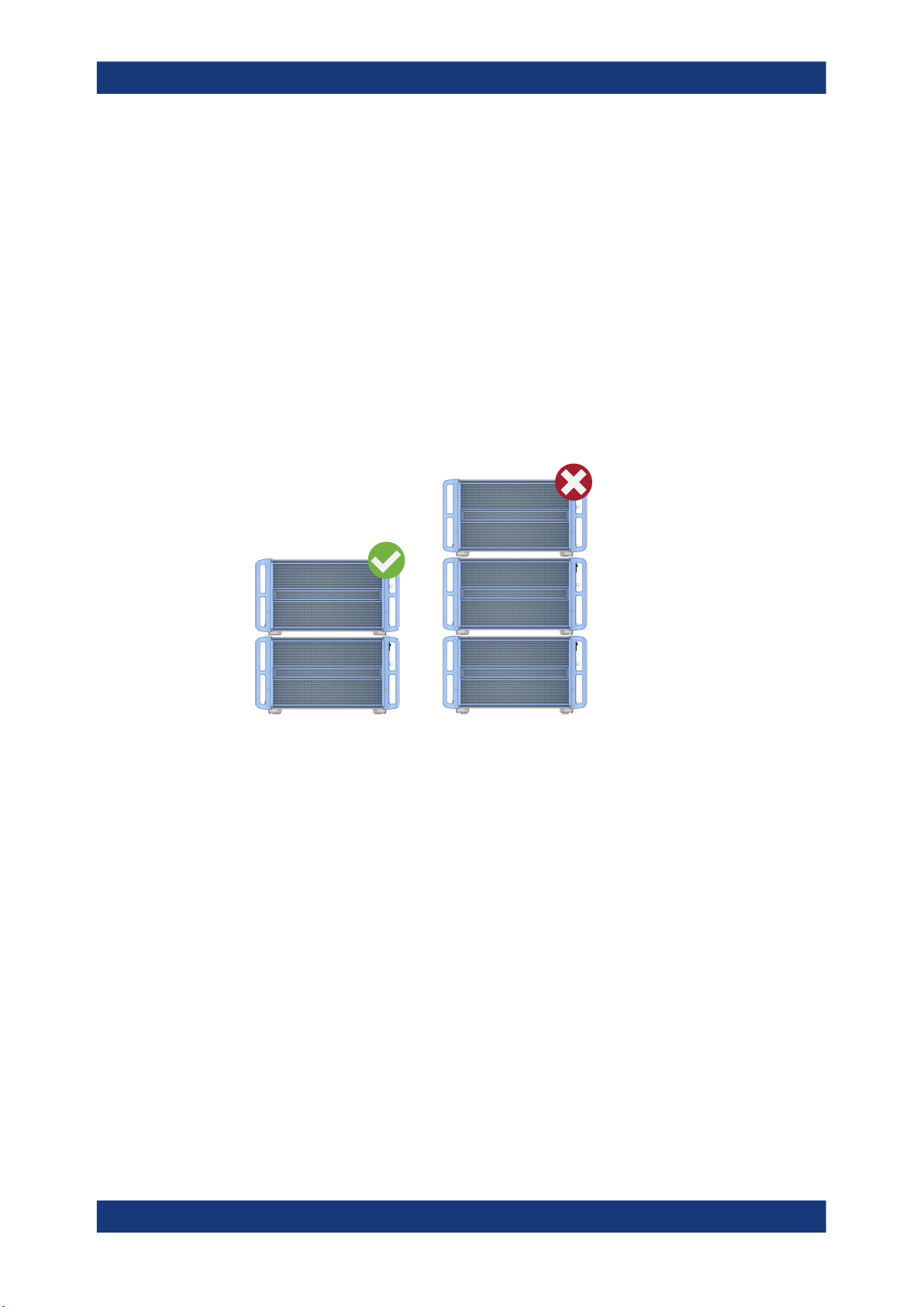
WARNING! A stack of products can fall over and cause injury. Never stack more
2.
than two products. Otherwise, mount them in a rack.
Stack as follows:
● All products must have the same dimensions (width and length).
● Do not exceed a total load of 50 kg placed on the product at the bottom of the
stack.
Left
= Stacked correctly
Right = Stacked incorrectly, too many products
NOTICE! Overheating can damage the product.
3.
Prevent overheating as follows:
● Keep a minimum distance of 10 cm between the fan openings of the product
and any object in the vicinity.
● Do not place the product next to heat-generating equipment such as radiators
or other products.
4.2.4.2 Mounting the R&S FSMR3 in a rack
To prepare the rack
1. Observe the requirements and instructions in "Setting up the product" on page 6.
NOTICE! Insufficient airflow can cause overheating and damage the product.
2.
Design and implement an efficient ventilation concept for the rack.
14User Manual 1179.0116.02 ─ 03
R&S®FSMR3000
Getting started
Preparing for use
To mount the R&S FSMR3 in a rack
1. Use an adapter kit to prepare the R&S FSMR3 for rack mounting.
a) Order the rack adapter kit designed for the R&S FSMR3. For the order number,
see the data sheet.
b) Mount the adapter kit. Follow the assembly instructions provided with the
adapter kit.
2. Lift the R&S FSMR3 to shelf height.
3. Grab the handles and push the R&S FSMR3 onto the shelf until the rack brackets
fit closely to the rack.
4. Tighten all screws in the rack brackets with a tightening torque of 1.2 Nm to secure
the R&S FSMR3 in the rack.
To unmount the R&S FSMR3 from a rack
1. Loosen the screws at the rack brackets.
2. Remove the R&S FSMR3 from the rack.
3. If placing the R&S FSMR3 on a bench top again, unmount the adapter kit from the
R&S FSMR3. Follow the instructions provided with the adapter kit.
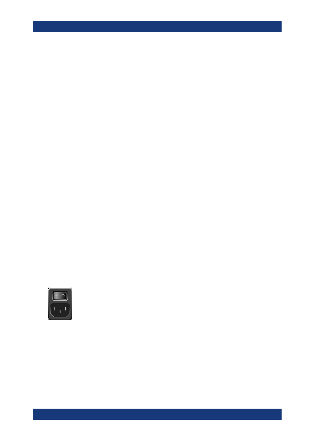
4.2.5 Connecting the AC power
In the standard version, the R&S FSMR3 is equipped with an AC power supply connector.
The R&S FSMR3 can be used with different AC power voltages and adapts itself automatically to it. Refer to the data sheet for the requirements of voltage and frequency.
For safety information, see "Connecting to power" on page 6.
To connect the AC power
1. Plug the AC power cable into the AC power connector on the rear panel of the
instrument. Only use the AC power cable delivered with the R&S FSMR3.
2. Plug the AC power cable into a power outlet with ground contact.
The required ratings are listed next to the AC power connector and in the data
sheet.
For details on the connector, refer to Chapter 4.3.2.1, "AC power supply connection
and main power switch", on page 35.
15User Manual 1179.0116.02 ─ 03

R&S®FSMR3000
4.2.6 Switching the instrument on and off
Getting started
Preparing for use
Table 4-1: Overview of power states
Status LED on Power key Position of main power switch
Off
Standby
Ready
gray
orange
green
[0]
[I]
[I]
To switch on the R&S FSMR3
The R&S FSMR3 is off but connected to power.
1. Set the switch on the power supply to position [I].
See Chapter 4.3.2.1, "AC power supply connection and main power switch",
on page 35.
The LED of the Power key is orange.
See Chapter 4.3.1.1, "Power key", on page 26.
2. Press the Power key.
See Chapter 4.3.1.1, "Power key", on page 26.
The LED changes to green.
The R&S FSMR3 boots.
After booting, the instrument is ready for operation.
To shut down the product
The product is in the ready state.
► Press the [Power] key.
The operating system shuts down. The LED changes to orange.
If the instrument temperature exceeds the limit specified in the data sheet, the
R&S FSMR3 automatically shuts down to protect the instrument from damage.
To disconnect from power
The R&S FSMR3 is in the standby state.
NOTICE! Risk of data loss. If you disconnect the product from power when it is in
1.
the ready state, you can lose settings and data. Shut it down first.
Set the switch on the power supply to position [0].
See Chapter 4.3.2.1, "AC power supply connection and main power switch",
on page 35.
The LED of the Power key is switched off.
2. Disconnect the R&S FSMR3 from the power source.
16User Manual 1179.0116.02 ─ 03

R&S®FSMR3000
4.2.7 Connecting to LAN
Getting started
Preparing for use
You can connect the instrument to a LAN for remote operation via a PC.
Provided the network administrator has assigned you the appropriate rights and adapted the Windows firewall configuration, you can use the interface, for example:
●
To transfer data between a controlling device and the test device, e.g. to run a
remote control program
●
To access or control the measurement from a remote computer using the "Remote
Desktop" application (or a similar tool)
●
To connect external network devices (e.g. printers)
●
To transfer data from a remote computer and back, e.g. using network folders
Network environment
Before connecting the product to a local area network (LAN), consider the following:
●
Install the latest firmware to reduce security risks.
●
For internet or remote access, use secured connections, if applicable.
●
Ensure that the network settings comply with the security policies of your company.
Contact your local system administrator or IT department before connecting your
product to your company LAN.
●
When connected to the LAN, the product may potentially be accessed from the
internet, which may be a security risk. For example, attackers might misuse or
damage the product. For more information about IT security and how to operate
the product in a secure LAN environment, see the Rohde & Schwarz white paper
1EF96: Malware Protection Windows 10.
NOTICE! Risk of network failure.
►
Consult your network administrator before performing the following tasks:
● Connecting the instrument to the network
● Configuring the network
● Changing IP addresses
● Exchanging hardware
Errors can affect the entire network.
Connect the R&S FSMR3 to the LAN via the LAN interface on the rear panel of the
instrument.
Windows automatically detects the network connection and activates the required
drivers.
By default, the R&S FSMR3 is configured to use DHCP and no static IP address is
configured.
The default instrument name is <Type><variant>-<serial_number>, for example,
FSMR3026-123456. For information on determining the serial number, see Chap-
ter 4.3.2.14, "Device ID", on page 38.
17User Manual 1179.0116.02 ─ 03

R&S®FSMR3000
4.2.8 Connecting a keyboard
Getting started
Preparing for use
For more information on LAN configuration, see Chapter 11.7, "How to set up a net-
work and remote control", on page 365.
The keyboard is detected automatically when it is connected. The default input language is English – US.
However, you can also connect foreign language keyboards; currently the following
languages are supported for the R&S FSMR3:
●
German
●
Swiss
●
French
●
Russian
To configure the keyboard language
1. To access the Windows operating system, press the Windows key on the external
keyboard.
2. Select "Start > Settings > Time & language > Region & language > Add a language" .
4.2.9 Connecting an external monitor
You can connect an external monitor (or projector) to the "DVI" or "Display port" connector on the rear panel of the R&S FSMR3 (see also Chapter 4.3.2.2, "Display port
and DVI", on page 35).
Screen resolution and format
The touchscreen of the R&S FSMR3 is calibrated for a 16:10 format. If you connect a
monitor or projector using a different format (e.g. 4:3), the calibration is not correct and
the screen does not react to your touch actions properly.
The touchscreen has a screen resolution of 1280x800 pixels. Usually, the display of
the external monitor is a duplicate of the instrument's monitor.
If you configure the external monitor to be used as the only display in the Windows
configuration dialog box ("Show only on 2"), the maximum screen resolution of the
monitor is used. In this case, you can maximize the R&S FSMR3 application window
and see even more details. You cannot change the monitor's screen resolution via the
standard Windows configuration dialog box.
However, you can restore the default instrument resolution (1280x800) on the monitor
using the instrument function "Setup" > "Display" > "Configure Monitor" > "Screen Resolution: Restore to default".
The R&S FSMR3 supports a minimum resolution of 1280x768 pixels.
1. Connect the external monitor to the R&S FSMR3.
18User Manual 1179.0116.02 ─ 03

R&S®FSMR3000
Getting started
Preparing for use
2. Press the [Setup] key.
3. Press the "Display" softkey.
4. Select the "Configure Monitor" tab in the "Display" dialog box.
The standard Windows "Screen Resolution" dialog box is displayed.
5. Select the instrument for display:
● "Display 1": internal monitor only
● "Display 2": external monitor only
● "Duplicate": both internal and external monitor
6. Tap "Apply" to try out the settings before they are accepted permanently, then you
can easily return to the previous settings, if necessary.
7. Select "OK" if the settings are suitable.
4.2.10 Windows operating system
The instrument contains the Windows 10 operating system which has been configured
according to the instrument's features and needs. Changes in the system setup are
only required when peripherals like a keyboard or a printer are installed or if the network configuration does not comply with the default settings. After the R&S FSMR3 is
started, the operating system boots and the instrument firmware is started automatically.
19User Manual 1179.0116.02 ─ 03

R&S®FSMR3000
Getting started
Preparing for use
Tested software
The drivers and programs used on the instrument under Windows 10 are adapted to
the instrument. Only install update software released by Rohde & Schwarz to modify
existing instrument software.
You can install additional software on the instrument; however, additional software can
impair instrument function. Thus, run only programs that Rohde & Schwarz has tested
for compatibility with the instrument software.
The following program packages have been tested:
●
Symantec Endpoint Security – virus-protection software
●
FileShredder - for reliable deletion of files on the hard disk
Service packs and updates
Microsoft regularly creates security updates and other patches to protect Windowsbased operating systems. They are released through the Microsoft Update website and
associated update server. Update instruments using Windows regularly, especially
instruments that connect to a network.
Firewall settings
A firewall protects an instrument by preventing unauthorized users from gaining access
to it through a network. Rohde & Schwarz highly recommends using the firewall on
your instrument. Rohde & Schwarz instruments are shipped with the Windows firewall
enabled. All ports and connections for remote control are enabled.
Note that changing firewall settings requires administrator rights.
Virus protection
Take appropriate steps to protect your instruments from infection. Use strong firewall
settings and scan any removable storage device used with a Rohde & Schwarz instrument regularly. It is also recommended that you install anti-virus software on the instrument. Rohde & Schwarz does NOT recommend running anti-virus software in the
background ("on-access" mode) on Windows-based instruments, due to potentially
degrading instrument performance. However, Rohde & Schwarz does recommend running it during non-critical hours.
For details and recommendations, see the following Rohde & Schwarz white paper:
●
1EF96: Malware Protection Windows 10
To access the "Start" menu
The Windows "Start" menu provides access to the Windows 10 functionality and installed programs.
► Select the "Windows" icon in the toolbar, or press the "Windows" key or the [CTRL
+ ESC] key combination on the (external) keyboard.
The "Start" menu and the Windows taskbar are displayed.
20User Manual 1179.0116.02 ─ 03

R&S®FSMR3000
4.2.11 Logging on
Getting started
Preparing for use
The Windows taskbar also provides quick access to commonly used programs, for
example Paint or WordPad. IECWIN, the auxiliary remote control tool provided free of
charge and installed by Rohde & Schwarz, is also available from the taskbar or "Start"
menu.
For details on the IECWIN tool, see Chapter 11.4, "The IECWIN tool", on page 337.
All necessary system settings can be defined in the "Start > Settings" menu.
For required settings, refer to the Windows 10 documentation and to the hardware
description.
Windows 10 requires that users identify themselves by entering a user name and password in a login window. By default, the R&S FSMR3 provides two user accounts:
●
"Instrument" : a standard user account with limited access
●
"Admin" or "Administrator" (depends on firmware image): an administrator
account with unrestricted access to the computer/domain
Some administrative tasks require administrator rights (e.g. the configuration of a LAN
network). Refer to the description of the basic instrument Setup ([Setup] menu) to find
out which functions are affected.
Secure user mode
If the secure user mode option (R&S FSMR3-K33) is installed, an additional account is
provided: the "SecureUser".
The "SecureUser" is a standard user account with limited functionality. In particular,
administrative tasks such as LAN configuration or general instrument settings are not
available. Furthermore, for a "SecureUser", data that the R&S FSMR3 normally stores
on the solid-state drive is redirected to volatile memory instead. You can access data
that is stored in volatile memory during the current instrument session. However, when
the instrument’s power is removed, all data in volatile memory is erased.
For details, see Chapter 9.2, "Protecting data using the secure user mode",
on page 237.
Passwords
For all default user accounts, the initial password is 894129. Note that this password is
very weak, and we strongly recommend that you change the password for both users
after initial login. An administrator can change the password in Windows 10 for any
user at any time via "Start > Settings > Account > SignIn Options > Password >
Change".
21User Manual 1179.0116.02 ─ 03

R&S®FSMR3000
Getting started
Preparing for use
Auto-login
When shipped, the instrument automatically logs on the default "Instrument" user to
Windows 10 using the default password. This function is active until an administrator
explicitly deactivates it or changes the password.
Changing the password and use of auto-login function
Note that when you change the default password, the default auto-login function no
longer works!
In this case, you must enter the new password manually to log on.
Adapting the auto-login function to a new password
If you change the password that is used during auto-login, this function no longer
works. Adapt the settings for the auto-login function first.
1. Select the "Windows" icon in the toolbar to access the operating system of the
R&S FSMR3 (see also "To access the "Start" menu" on page 20).
2. Open the C:\R_S\INSTR\USER\user\AUTOLOGIN.REG file in any text editor
(e.g. Notepad).
3. In the line "DefaultPassword"="894129", replace the default password
(894129) by the new password for automatic login.
4. Save the changes to the file.
5. In the Windows "Start" menu, select "Run".
The "Run" dialog box is displayed.
6. Enter the command C:\R_S\INSTR\USER\user\AUTOLOGIN.REG.
7. Press the [ENTER] key to confirm.
The auto-login function is reactivated with the changed password. It will be applied
the next time the instrument is switched on.
Switching users when using the auto-login function
Which user account is used is defined during login. If auto-login is active, the login window is not displayed. However, you can switch the user account to be used even when
the auto-login function is active.
1. Select the "Windows" icon in the toolbar to access the operating system of the
R&S FSMR3 (see also "To access the "Start" menu" on page 20).
2. Press [CTRL] + [ALT] + [DEL], then select "Sign out".
The "Login" dialog box is displayed, in which you can enter the different user
account name and password.
For information on deactivating and reactivating the auto-login function, see "Deactivat-
ing the auto-login function" on page 374.
22User Manual 1179.0116.02 ─ 03

R&S®FSMR3000
4.2.12 Checking the supplied options
4.2.13 Performing a self-alignment
Getting started
Preparing for use
The instrument can be equipped with both hardware and firmware options. To check
whether the installed options correspond to the options indicated on the delivery note,
proceed as follows.
1. Press the [SETUP] key.
2. Press the "System Config" softkey.
3. Switch to the "Versions + Options" tab in the "System Configuration" dialog box.
A list with hardware and firmware information is displayed.
4. Check the availability of the hardware options as indicated in the delivery note.
When temperature changes occur in the environment of the R&S FSMR3, or after
updating the firmware, you have to perform a self-alignment to align the data to a reference source.
During self-alignment, do not connect a signal to the RF input connector. Running a
self-alignment with a signal connected to the RF input can lead to false measurement
results.
Performing a self-alignment
Before performing this alignment, make sure that the instrument has reached its operating temperature (for details, refer to the data sheet).
A message in the status bar ("Instrument warming up...") indicates that the operating
temperature has not yet been reached.
Depending on the installation settings, an automatic self-alignment is performed each
time the instrument is switched on. A dialog box is displayed indicating how much
warm-up time is still required before self-alignment can be performed.
1. Press the [Setup] key.
2. Press the "Alignment" softkey.
3. Select the "Start Self Alignment" button in the "Alignment" dialog box.
Once the system correction values have been calculated successfully, a message
is displayed.
To display the alignment results again later
●
Press the [SETUP] key.
●
Press the "Alignment" softkey.
23User Manual 1179.0116.02 ─ 03

R&S®FSMR3000
4.2.14 Considerations for test setup
Getting started
Instrument tour
Cable selection and electromagnetic interference (EMI)
Electromagnetic interference (EMI) can affect the measurement results.
To suppress electromagnetic radiation during operation:
●
Use high-quality shielded cables, for example, double-shielded RF and LAN
cables.
●
Always terminate open cable ends.
●
Ensure that connected external devices comply with EMC regulations.
Signal input and output levels
Information on signal levels is provided in the data sheet and on the instrument, next to
the connector. Keep the signal levels within the specified ranges to avoid damage to
the R&S FSMR3 and connected devices.
4.3 Instrument tour
On the instrument tour, you can learn about the different control elements and connectors on the front and back panel of the R&S FSMR3.
● The front panel........................................................................................................24
● The rear panel.........................................................................................................33
4.3.1 The front panel
This chapter describes the front panel, including all function keys and connectors.
24User Manual 1179.0116.02 ─ 03

R&S®FSMR3000
Getting started
Instrument tour
1
Figure 4-1: Front panel view of R&S FSMR3
2
3
4
5
6789101112131415
1 = Touchscreen
2 = Function keys
3 = Navigation controls
4 = TRIGGER INPUT/OUTPUT
5 = RF INPUT 50 Ω
6 = POWER SENSOR connector
7 = LO AUX INPUT CH1/CH2
8 = NOISE SOURCE CONTROL
9 = PROBE connector
10 = SMART NOISE SOURCE connector
11 = USB connectors
12 = Volume control
13 = Headphones connector
14 = SYSTEM keys
15 = POWER key
● Power key............................................................................................................... 26
● USB.........................................................................................................................26
● System keys............................................................................................................26
● Touchscreen............................................................................................................27
● Function keys..........................................................................................................28
● Navigation controls..................................................................................................30
● Undo/redo keys.......................................................................................................31
● Trigger input / output...............................................................................................31
● RF input 50 ohm......................................................................................................31
● Power sensor.......................................................................................................... 32
● Noise source control............................................................................................... 32
● Probe.......................................................................................................................32
25User Manual 1179.0116.02 ─ 03
R&S®FSMR3000
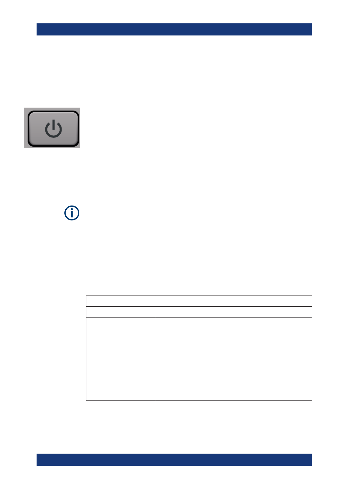
4.3.1.1 Power key
4.3.1.2 USB
Getting started
Instrument tour
● Smart noise source................................................................................................. 32
● AF out and volume..................................................................................................32
● Keypad....................................................................................................................32
The power key is on the lower left corner of the front panel. It starts up and shuts down
the instrument.
See also "Connecting to power" on page 6.
The front panel provides three female USB connectors (USB-A) to connect devices like
a keyboard or a mouse. In addition, a memory stick can be connected to store and
reload instrument settings and measurement data.
The rear panel provides further USB connectors, including a male (USB-B) connector.
See Chapter 4.3.2.4, "USB", on page 36.
All USB connectors support standard 2.0.
4.3.1.3 System keys
System keys set the instrument to a predefined state, change basic settings, and provide print and display functions.
A detailed description of the corresponding functions is provided in the user manual.
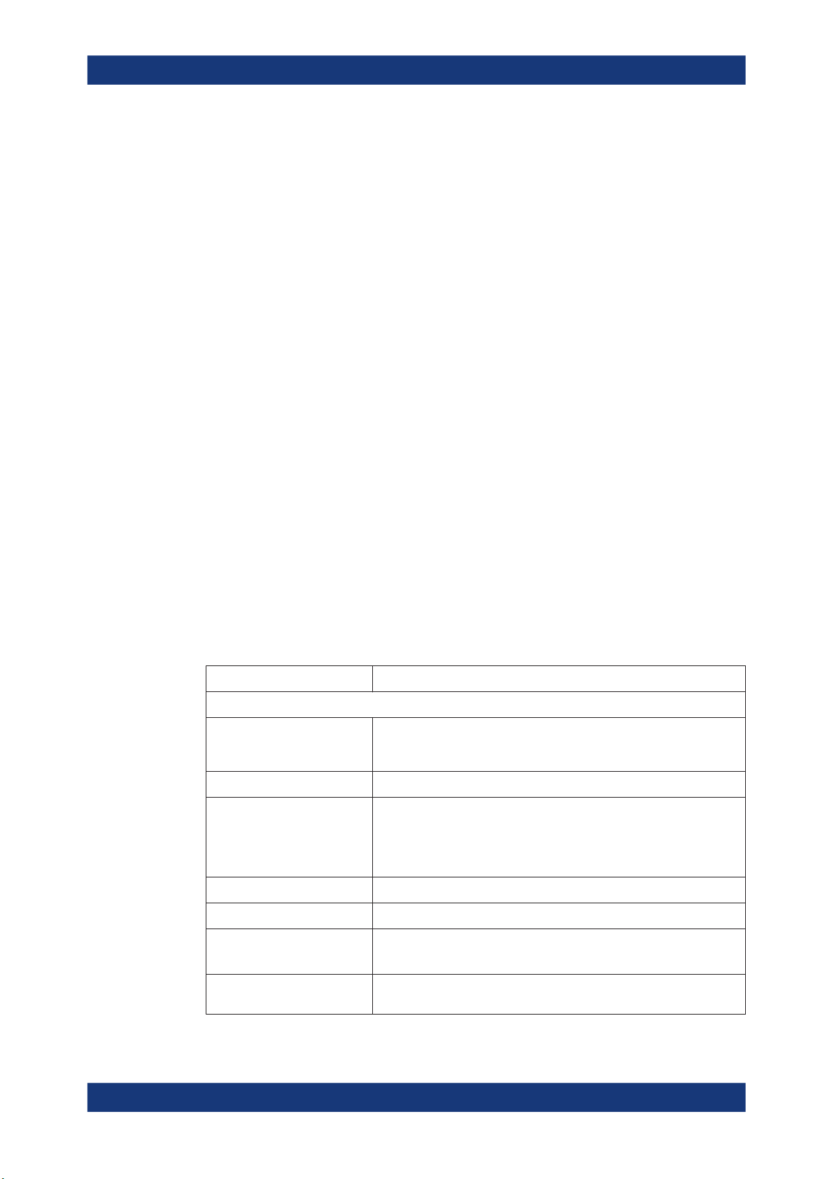
Table 4-2: System keys
System key Assigned functions
[Preset] Resets the instrument to the default state.
[Setup]
[Print] Provides print and screenshot functions
Provides basic instrument configuration functions, e.g.:
●
Reference frequency (external/internal), noise source
●
Date, time, display configuration
●
LAN interface
●
Self-alignment
●
Firmware update and enabling of options
●
Information about instrument configuration incl. firmware version and
System error messages
●
Service support functions (self-test etc.)
[File] Provides data management functions such as saving and recalling instru-
ment settings or importing and exporting data.
26User Manual 1179.0116.02 ─ 03

R&S®FSMR3000
4.3.1.4 Touchscreen
Getting started
Instrument tour
System key Assigned functions
Switches between the on-screen keyboard display:
●
At the top of the screen
●
At the bottom of the screen
●
Off
[Mode] Provides the selection between applications
All measurement results are displayed on the screen on the front panel. Additionally,
the screen display provides status and setting information and allows you to switch
between various measurement tasks. The screen is touch-sensitive, offering an alternative means of user interaction for quick and easy handling of the instrument.
1
Figure 4-2: Touchscreen elements
2
9
3
4
5
8
6
7
1 = Toolbar with standard application functions, e.g. print, save/open file etc.
2 = Tabs for individual measurement channels
3 = Channel bar for firmware and measurement settings
4 = Window title bar with diagram-specific (trace) information
5 = Measurement results area
6 = Input field for measurement setting
7 = Softkeys for function access
8 = Diagram footer with diagram-specific information, depending on application
9 = Instrument status bar with error messages, progress bar and date/time display
27User Manual 1179.0116.02 ─ 03
R&S®FSMR3000
Getting started
Instrument tour
All measurement results are displayed on the screen on the front panel. Additionally,
the screen display provides status and setting information and allows you to switch
between various measurement tasks. The screen is touch-sensitive, offering an alternative means of user interaction for quick and easy handling of the instrument. Any
user interface elements that react to a click by a mouse pointer also react to a tap on
the screen, and vice versa. Using touchscreen gestures, you can perform the following
tasks:
●
Changing a setting
●
Changing the display
●
Moving a marker
●
Zooming into a diagram
●
Selecting a new evaluation method
●
Scrolling through a result list or table
●
Saving or printing results and settings
To imitate a right-click by mouse using the touchscreen, for example to open a contextsensitive menu for a specific item, press the screen for about 1 second.
For details on touchscreen gestures, see Chapter 4.5.4, "Touchscreen gestures",
on page 73.
4.3.1.5 Function keys
Function keys provide access to the most common measurement settings and functions.
A detailed description of the corresponding functions is provided in the user manual.
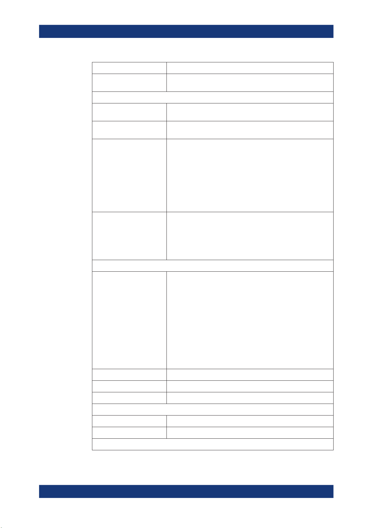
Table 4-3: Function keys
Function key Assigned functions
Basic measurement settings
[Freq.] Sets the center frequency and the start and stop frequencies for the fre-
[Span] Sets the frequency span to be analyzed.
[Ampt. / Scale] Sets the reference level, the displayed dynamic range, the RF attenua-
[Auto Set] Enables automatic settings for level, frequency or sweep type Mode.
quency range under consideration. This key is also used to set the frequency offset and the signal track function.
tion and the unit for the level display.
Sets the level offset and the Input impedance.
Activates the preamplifier (option RF Preamplifier, R&S FSMR3-B24).
[BW] Sets the resolution bandwidth and the Video bandwidth.
[Sweep] Sets the sweep time and the number of measurement points.
Selects continuous measurement or single measurement.
[Trace] Configures the measured data acquisition and the analysis of the mea-
surement data.
28User Manual 1179.0116.02 ─ 03
R&S®FSMR3000
Getting started
Instrument tour
Function key Assigned functions
[Trigger] Sets the trigger mode, the trigger threshold, the trigger delay, and the
gate configuration for gated sweep.
Marker functions
[Marker] Sets and positions the absolute and relative measurement markers
(markers and delta markers).
[Peak Search] Performs a peak search for active marker. If no marker is active, normal
marker 1 is activated and the peak search is performed for it.
[Marker Function] Provides additional analysis functions of the measurement markers:
Frequency counter (Sig Count)
Fixed reference point for relative measurement markers (Ref Fixed)
Noise marker (Noise Meas)
Phase noise (Phase Noise)
n dB down function
AM/FM audio demodulation
Peak list
[Marker ->] Used for search functions of the measurement markers (maximum/mini-
mum of the trace).
Assigns the marker frequency to the center frequency, and the marker
level to the reference level.
Restricts the search area (Search Limits) and characterizes the maxi-
mum points and minimum points (Peak Excursion).
Measurement and evaluation functions
[Meas] Provides the measurement functions.
Measurement of multicarrier adjacent channel power (Ch Power ACLR)
Carrier to noise spacing (C/N C/N0)
Occupied bandwidth (OBW)
Spectrum emission mask measurement (Spectrum Emission Mask)
Spurious emissions (Spurious Emissions)
Measurement of time domain power (Time Domain Power)
Signal statistics: amplitude probability distribution (APD) and cumulative
complementary distribution function (CCDF)
Third-order intercept point (TOI)
AM modulation depth (AM Mod Depth)
[Meas Config] Used to define measurement configuration.
[Lines] Configures display lines and limit lines.
[Input/Output] Displays softkeys for In/Out functions.
Measurement start functions
[Run Single] Starts a single new measurement (Single Sweep Mode).
[Run Cont.] Starts a continuous measurement (Continuous Sweep Mode).
Function execution (in navigation controls area)
29User Manual 1179.0116.02 ─ 03
R&S®FSMR3000
4.3.1.6 Navigation controls
Getting started
Instrument tour
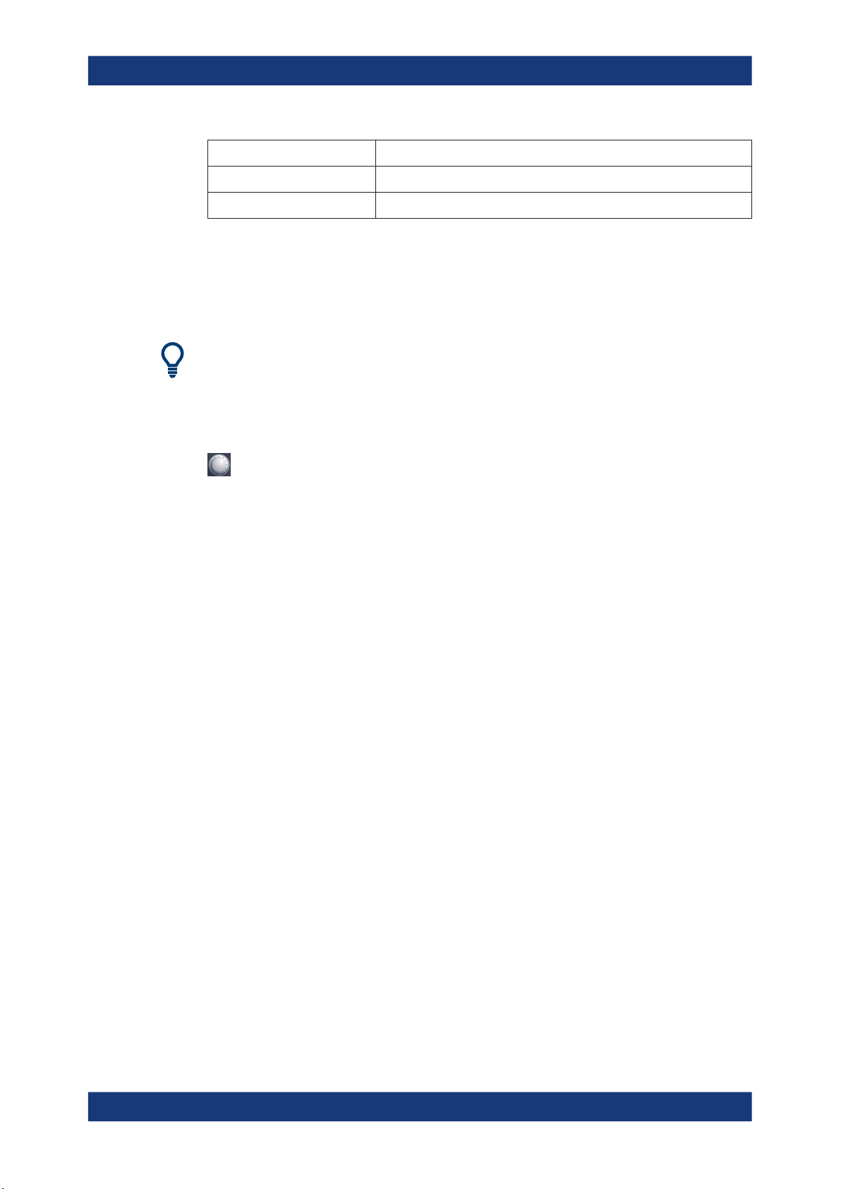
Function key Assigned functions
[Undo] Reverts last operation
[Redo] Repeats previously reverted operation.
The navigation controls include a rotary knob, navigation keys, and Undo / Redo keys.
They allow you to navigate within the display or within dialog boxes.
Navigating in tables
The easiest way to navigate within tables (both in result tables and configuration
tables) is to scroll through the entries with your finger on the touchscreen.
Rotary knob
The rotary knob has several functions:
●
For numeric entries: increments (clockwise direction) or decrements (counterclockwise direction) the instrument parameter at a defined step width
●
In lists: toggles between entries
●
For markers, limit lines, and other graphical elements on the screen: moves their
position
●
For active scroll bars: moves the scroll bar vertically
●
For dialog boxes: Same effect as the Enter key when pressed
Navigation keys
The navigation keys can be used alternatively to the rotary knob to navigate through
dialog boxes, diagrams or tables.
Arrow Up/Arrow Down Keys
The <arrow up> or <arrow down> keys do the following:
●
For numeric entries: increments (Arrow Up) or decrements (Arrow Down) the
instrument parameter at a defined step width
●
In a list: scrolls forward and backward through the list entries
●
In a table: moves the selection bar vertically
●
In windows or dialog boxes with a vertical scroll bar: moves the scroll bar
Arrow Left/Arrow Right Keys
The <arrow left> or <arrow right> keys do the following:
●
In an alphanumeric edit dialog box, move the cursor.
●
In a list, scroll forward and backward through the list entries.
30User Manual 1179.0116.02 ─ 03
 Loading...