

Page 1
R&S
®
FS
-
K30
Figure and
Application Firmware for Noise
Gain Measurments for R&S®Analyzers
Software Manual
1300.6637.42 – 03
Software Manual
Test and Measurement
Page 2

The Software Manual describes the following R&S®FS-K30 option andmodels:
( R&S
( R&S
(
( R&S
( R&S
( R&S
®
FSG
®
FSMR (only for ser. no. >200 000)
®
R&S
SP
F
®
FSQ
®
FSU
®
FSUP
The firmware of the instrument makes use of several valuable open source software packages. the most important of them are listed
below, together with their corresponding open source license. The verbatimlicense texts are provided on the user documentation CD-
ROM (included in delivery).
Package Link License
Xitam i http://www.xitami.com 2.5b6
Rohde&Schwarz would like to thank the open source community for their valuable contribution to embedded computing.
© 2008 Rohde & Schwarz GmbH & Co. KG
81671 Munich, Germany
Printed in Germany – Subject to change – Data without tolerance limits is not binding.
®
R&S
is a registered trademark of Rohde & Schwarz GmbH & Co. KG.
Trade names are trademarks of the owners.
The following abbreviations are used throughout this manual:
®
FS-K30 is abbreviated as R&S FS-K30.
R&S
Page 3
Basic Safety Instructions
Always read through and comply with the following safety instructions!
All plants and locations of the Rohde & Schwarz group of companies make every effort to keep the safety
standards of our products up to date and to offer our customers the highest possible degree of safety. Our
products and the auxiliary equipment they require are designed, built and tested in accordance with the
safety standards that apply in each case. Compliance with these standards is continuously monitored by
our quality assurance system. The product described here has been designed, built and tested in
accordance with the attached EC Certificate of Conformity and has left the manufacturer’s plant in a
condition fully complying with safety standards. To maintain this condition and to ensure safe operation,
you must observe all instructions and warnings provided in this manual. If you have any questions
regarding these safety instructions, the Rohde & Schwarz group of companies will be happy to answer
them.
Furthermore, it is your responsibility to use the product in an appropriate manner. This product is designed
for use solely in industrial and laboratory environments or, if expressly permitted, also in the field and must
not be used in any way that may cause personal injury or property damage. You are responsible if the
product is used for any intention other than its designated purpose or in disregard of the manufacturer's
instructions. The manufacturer shall assume no responsibility for such use of the product.
The product is used for its designated purpose if it is used in accordance with its product documentation
and within its performance limits (see data sheet, documentation, the following safety instructions). Using
the product requires technical skills and a basic knowledge of English. It is therefore essential that only
skilled and specialized staff or thoroughly trained personnel with the required skills be allowed to use the
product. If personal safety gear is required for using Rohde & Schwarz products, this will be indicated at
the appropriate place in the product documentation. Keep the basic safety instructions and the product
documentation in a safe place and pass them on to the subsequent users.
Observing the safety instructions will help prevent personal injury or damage of any kind caused by
dangerous situations. Therefore, carefully read through and adhere to the following safety instructions
before and when using the product. It is also absolutely essential to observe the additional safety
instructions on personal safety, for example, that appear in relevant parts of the product documentation. In
these safety instructions, the word "product" refers to all merchandise sold and distributed by the Rohde &
Schwarz group of companies, including instruments, systems and all accessories.
Symbols and safety labels
Notice, general
danger location
Observe product
documentation
ON/OFF supply
voltage
Caution
when
handling
heavy
equipment
Standby
indication
Danger of
electric
shock
Direct current
(DC)
Warning!
Hot surface
Alternating current
(AC)
PE terminal Ground Ground
terminal
Direct/alternating
current (DC/AC)
Device fully protected by
double (reinforced) insulation
Be careful when
handling
electrostatic
sensitive
devices
1171.0000.42-05.00 Page 1
Page 4

Basic Safety Instructions
Tags and their meaning
The following signal words are used in the product documentation in order to warn the reader about risks
and dangers.
indicates a hazardous situation which, if not avoided, will result in death or
serious injury.
indicates a hazardous situation which, if not avoided, could result in death or
serious injury.
indicates a hazardous situation which, if not avoided, could result in minor or
moderate injury.
indicates the possibility of incorrect operation which can result in damage to
the product.
In the product documentation, the word ATTENTION is used synonymously.
These tags are in accordance with the standard definition for civil applications in the European Economic
Area. Definitions that deviate from the standard definition may also exist in other economic areas or
military applications. It is therefore essential to make sure that the tags described here are always used
only in connection with the related product documentation and the related product. The use of tags in
connection with unrelated products or documentation can result in misinterpretation and in personal injury
or material damage.
Operating states and operating positions
The product may be operated only under the operating conditions and in the positions specified by the
manufacturer, without the product's ventilation being obstructed. If the manufacturer's specifications are
not observed, this can result in electric shock, fire and/or serious personal injury or death. Applicable local
or national safety regulations and rules for the prevention of accidents must be observed in all work
performed.
1. Unless otherwise specified, the following requirements apply to Rohde & Schwarz products:
predefined operating position is always with the housing floor facing down, IP protection 2X, pollution
severity 2, overvoltage category 2, use only indoors, max. operating altitude 2000 m above sea level,
max. transport altitude 4500 m above sea level. A tolerance of ±10 % shall apply to the nominal
voltage and ±5 % to the nominal frequency.
2. Do not place the product on surfaces, vehicles, cabinets or tables that for reasons of weight or stability
are unsuitable for this purpose. Always follow the manufacturer's installation instructions when
installing the product and fastening it to objects or structures (e.g. walls and shelves). An installation
that is not carried out as described in the product documentation could result in personal injury or
death.
3. Do not place the product on heat-generating devices such as radiators or fan heaters. The ambient
temperature must not exceed the maximum temperature specified in the product documentation or in
the data sheet. Product overheating can cause electric shock, fire and/or serious personal injury or
death.
1171.0000.42-05.00 Page 2
Page 5

Basic Safety Instructions
Electrical safety
If the information on electrical safety is not observed either at all to the extent necessary, electric shock,
fire and/or serious personal injury or death may occur.
1. Prior to switching on the product, always ensure that the nominal voltage setting on the product
matches the nominal voltage of the AC supply network. If a different voltage is to be set, the power
use of the product may have to be changed accordingly.
f
2. In the case of products of safety class I with movable power cord and connector, operation is
permitted only on sockets with an earthing contact and protective earth connection.
3. Intentionally breaking the protective earth connection either in the feed line or in the product itself is
not permitted. Doing so can result in the danger of an electric shock from the product. If extension
cords or connector strips are implemented, they must be checked on a regular basis to ensure that
they are safe to use.
4. If the product does not have a power switch for disconnection from the AC supply network, the plug of
the connecting cable is regarded as the disconnecting device. In such cases, always ensure that the
power plug is easily reachable and accessible at all times (corresponding to the length of connecting
cable, approx. 2 m). Functional or electronic switches are not suitable for providing disconnection from
the AC supply network. If products without power switches are integrated into racks or systems, a
disconnecting device must be provided at the system level.
5. Never use the product if the power cable is damaged. Check the power cable on a regular basis to
ensure that it is in proper operating condition. By taking appropriate safety measures and carefully
laying the power cable, you can ensure that the cable will not be damaged and that no one can be
hurt by, for example, tripping over the cable or suffering an electric shock.
6. The product may be operated only from TN/TT supply networks fused with max. 16 A (higher fuse
only after consulting with the Rohde & Schwarz group of companies).
7. Do not insert the plug into sockets that are dusty or dirty. Insert the plug firmly and all the way into the
socket. Otherwise, sparks that result in fire and/or injuries may occur.
8. Do not overload any sockets, extension cords or connector strips; doing so can cause fire or electric
shocks.
9. For measurements in circuits with voltages V
> 30 V, suitable measures (e.g. appropriate
rms
measuring equipment, fusing, current limiting, electrical separation, insulation) should be taken to
avoid any hazards.
10. Ensure that the connections with information technology equipment, e.g. PCs or other industrial
computers, comply with the IEC60950-1/EN60950-1 or IEC61010-1/EN 61010-1 standards that apply
in each case.
11. Unless expressly permitted, never remove the cover or any part of the housing while the product is in
operation. Doing so will expose circuits and components and can lead to injuries, fire or damage to the
product.
12. If a product is to be permanently installed, the connection between the PE terminal on site and the
product's PE conductor must be made first before any other connection is made. The product may be
installed and connected only by a licensed electrician.
13. For permanently installed equipment without built-in fuses, circuit breakers or similar protective
devices, the supply circuit must be fused in such a way that anyone who has access to the product, as
well as the product itself, is adequately protected from injury or damage.
1171.0000.42-05.00 Page 3
Page 6

Basic Safety Instructions
14. Use suitable overvoltage protection to ensure that no overvoltage (such as that caused by a bolt of
lightning) can reach the product. Otherwise, the person operating the product will be exposed to the
danger of an electric shock.
15. Any object that is not designed to be placed in the openings of the housing must not be used for this
purpose. Doing so can cause short circuits inside the product and/or electric shocks, fire or injuries.
6. Unless specified otherwise, products are not liquid-proof (see also section "Operating states and
1
operating positions", item 1. Therefore, the equipment must be protected against penetration by
liquids. If the necessary precautions are not taken, the user may suffer electric shock or the product
itself may be damaged, which can also lead to personal injury.
17. Never use the product under conditions in which condensation has formed or can form in or on the
product, e.g. if the product has been moved from a cold to a warm environment. Penetration by water
increases the risk of electric shock.
18. Prior to cleaning the product, disconnect it completely from the power supply (e.g. AC supply network
or battery). Use a soft, non-linting cloth to clean the product. Never use chemical cleaning agents such
as alcohol, acetone or diluents for cellulose lacquers.
Operation
1. Operating the products requires special training and intense concentration. Make sure that persons
who use the products are physically, mentally and emotionally fit enough to do so; otherwise, injuries
or material damage may occur. It is the responsibility of the employer/operator to select suitable
personnel for operating the products.
2. Before you move or transport the product, read and observe the section titled "Transport".
3. As with all industrially manufactured goods, the use of substances that induce an allergic reaction
(allergens) such as nickel cannot be generally excluded. If you develop an allergic reaction (such as a
skin rash, frequent sneezing, red eyes or respiratory difficulties) when using a Rohde & Schwarz
product, consult a physician immediately to determine the cause and to prevent health problems or
stress.
4. Before you start processing the product mechanically and/or thermally, or before you take it apart, be
sure to read and pay special attention to the section titled "Waste disposal", item 1.
5. Depending on the function, certain products such as RF radio equipment can produce an elevated
level of electromagnetic radiation. Considering that unborn babies require increased protection,
pregnant women must be protected by appropriate measures. Persons with pacemakers may also be
exposed to risks from electromagnetic radiation. The employer/operator must evaluate workplaces
where there is a special risk of exposure to radiation and, if necessary, take measures to avert the
potential danger.
6. Should a fire occur, the product may release hazardous substances (gases, fluids, etc.) that can
cause health problems. Therefore, suitable measures must be taken, e.g. protective masks and
protective clothing must be worn.
7. If a laser product (e.g. a CD/DVD drive) is integrated into a Rohde & Schwarz product, absolutely no
other settings or functions may be used as described in the product documentation. The objective is to
prevent personal injury (e.g. due to laser beams).
1171.0000.42-05.00 Page 4
Page 7

Basic Safety Instructions
Repair and service
1. The product may be opened only by authorized, specially trained personnel. Before any work is
performed on the product or before the product is opened, it must be disconnected from the AC supply
network. Otherwise, personnel will be exposed to the risk of an electric shock.
2. Adjustments, replacement of parts, maintenance and repair may be performed only by electrical
xperts authorized by Rohde & Schwarz. Only original parts may be used for replacing parts relevant
e
to safety (e.g. power switches, power transformers, fuses). A safety test must always be performed
after parts relevant to safety have been replaced (visual inspection, PE conductor test, insulation
resistance measurement, leakage current measurement, functional test). This helps ensure the
continued safety of the product.
Batteries and rechargeable batteries/cells
If the information regarding batteries and rechargeable batteries/cells is not observed either at all or to the
extent necessary, product users may be exposed to the risk of explosions, fire and/or serious personal
injury, and, in some cases, death. Batteries and rechargeable batteries with alkaline electrolytes (e.g.
lithium cells) must be handled in accordance with the EN 62133 standard.
1. Cells must not be taken apart or crushed.
2. Cells or batteries must not be exposed to heat or fire. Storage in direct sunlight must be avoided.
Keep cells and batteries clean and dry. Clean soiled connectors using a dry, clean cloth.
3. Cells or batteries must not be short-circuited. Cells or batteries must not be stored in a box or in a
drawer where they can short-circuit each other, or where they can be short-circuited by other
conductive materials. Cells and batteries must not be removed from their original packaging until they
are ready to be used.
4. Keep cells and batteries out of the hands of children. If a cell or a battery has been swallowed, seek
medical aid immediately.
5. Cells and batteries must not be exposed to any mechanical shocks that are stronger than permitted.
6. If a cell develops a leak, the fluid must not be allowed to come into contact with the skin or eyes. If
contact occurs, wash the affected area with plenty of water and seek medical aid.
7. Improperly replacing or charging cells or batteries that contain alkaline electrolytes (e.g. lithium cells)
can cause explosions. Replace cells or batteries only with the matching Rohde & Schwarz type (see
parts list) in order to ensure the safety of the product.
8. Cells and batteries must be recycled and kept separate from residual waste. Rechargeable batteries
and normal batteries that contain lead, mercury or cadmium are hazardous waste. Observe the
national regulations regarding waste disposal and recycling.
Transport
1. The product may be very heavy. Therefore, the product must be handled with care. In some cases,
the user may require a suitable means of lifting or moving the product (e.g. with a lift-truck) to avoid
back or other physical injuries.
1171.0000.42-05.00 Page 5
Page 8

Informaciones elementales de seguridad
2. Handles on the products are designed exclusively to enable personnel to transport the product. It is
therefore not permissible to use handles to fasten the product to or on transport equipment such as
cranes, fork lifts, wagons, etc. The user is responsible for securely fastening the products to or on the
means of transport or lifting. Observe the safety regulations of the manufacturer of the means of
transport or lifting. Noncompliance can result in personal injury or material damage.
3. If you use the product in a vehicle, it is the sole responsibility of the driver to drive the vehicle safely
and properly. The manufacturer assumes no responsibility for accidents or collisions. Never use the
product in a moving vehicle if doing so could distract the driver of the vehicle. Adequately secure the
product in the vehicle to prevent injuries or other damage in the event of an accident.
Waste disposal
1. If products or their components are mechanically and/or thermally processed in a manner that goes
beyond their intended use, hazardous substances (heavy-metal dust such as lead, beryllium, nickel)
may be released. For this reason, the product may only be disassembled by specially trained
personnel. Improper disassembly may be hazardous to your health. National waste disposal
regulations must be observed.
2. If handling the product releases hazardous substances or fuels that must be disposed of in a special
way, e.g. coolants or engine oils that must be replenished regularly, the safety instructions of the
manufacturer of the hazardous substances or fuels and the applicable regional waste disposal
regulations must be observed. Also observe the relevant safety instructions in the product
documentation. The improper disposal of hazardous substances or fuels can cause health problems
and lead to environmental damage.
Informaciones elementales de seguridad
Es imprescindible leer y observar las siguientes instrucciones e informaciones de seguridad!
El principio del grupo de empresas Rohde & Schwarz consiste en tener nuestros productos siempre al día
con los estándares de seguridad y de ofrecer a nuestros clientes el máximo grado de seguridad. Nuestros
productos y todos los equipos adicionales son siempre fabricados y examinados según las normas de
seguridad vigentes. Nuestro sistema de garantía de calidad controla constantemente que sean cumplidas
estas normas. El presente producto ha sido fabricado y examinado según el certificado de conformidad
adjunto de la UE y ha salido de nuestra planta en estado impecable según los estándares técnicos de
seguridad. Para poder preservar este estado y garantizar un funcionamiento libre de peligros, el usuario
deberá atenerse a todas las indicaciones, informaciones de seguridad y notas de alerta. El grupo de
empresas Rohde & Schwarz está siempre a su disposición en caso de que tengan preguntas referentes a
estas informaciones de seguridad.
Además queda en la responsabilidad del usuario utilizar el producto en la forma debida. Este producto
está destinado exclusivamente al uso en la industria y el laboratorio o, si ha sido expresamente
autorizado, para aplicaciones de campo y de ninguna manera deberá ser utilizado de modo que alguna
persona/cosa pueda sufrir daño. El uso del producto fuera de sus fines definidos o sin tener en cuenta las
instrucciones del fabricante queda en la responsabilidad del usuario. El fabricante no se hace en ninguna
forma responsable de consecuencias a causa del mal uso del producto.
1171.0000.42-05.00 Page 6
Page 9
Informaciones elementales de seguridad
Se parte del uso correcto del producto para los fines definidos si el producto es utilizado conforme a las
indicaciones de la correspondiente documentación del producto y dentro del margen de rendimiento
definido (ver hoja de datos, documentación, informaciones de seguridad que siguen). El uso del producto
hace necesarios conocimientos técnicos y ciertos conocimientos del idioma inglés. Por eso se debe tener
en cuenta que el producto solo pueda ser operado por personal especializado o personas instruidas en
profundidad con las capacidades correspondientes. Si fuera necesaria indumentaria de seguridad para el
so de productos de Rohde & Schwarz, encontraría la información debida en la documentación del
u
producto en el capítulo correspondiente. Guarde bien las informaciones de seguridad elementales, así
como la documentación del producto, y entréguelas a usuarios posteriores.
Tener en cuenta las informaciones de seguridad sirve para evitar en lo posible lesiones o daños por
peligros de toda clase. Por eso es imprescindible leer detalladamente y comprender por completo las
siguientes informaciones de seguridad antes de usar el producto, y respetarlas durante el uso del
producto. Deberán tenerse en cuenta todas las demás informaciones de seguridad, como p. ej. las
referentes a la protección de personas, que encontrarán en el capítulo correspondiente de la
documentación del producto y que también son de obligado cumplimiento. En las presentes
informaciones de seguridad se recogen todos los objetos que distribuye el grupo de empresas
Rohde & Schwarz bajo la denominación de "producto", entre ellos también aparatos, instalaciones así
como toda clase de accesorios.
Símbolos y definiciones de seguridad
Aviso: punto de
peligro general
Observar la
documentación
del producto
Tensión de
alimentación de
PUESTA EN
MARCHA /
PARADA
Atención en
el manejo de
dispositivos
de peso
elevado
Indicación de
estado de
espera
(Standby)
Peligro de
choque
eléctrico
Corriente
continua (DC)
Advertencia:
superficie
caliente
Conexión a
conductor de
protección
Corriente alterna
(AC)
Conexión
a tierra
Corriente
continua /
Corriente alterna
(DC/AC)
Conexión
a masa
El aparato está protegido
en su totalidad por un
aislamiento doble
(reforzado)
Aviso: Cuidado
en el manejo de
dispositivos
sensibles a la
electrostática
(ESD)
1171.0000.42-05.00 Page 7
Page 10

Informaciones elementales de seguridad
Palabras de señal y su significado
En la documentación del producto se utilizan las siguientes palabras de señal con el fin de advertir contra
riesgos y peligros.
PELIGRO identifica un peligro inminente con riesgo elevado que
provocará muerte o lesiones graves si no se evita.
ADVERTENCIA identifica un posible peligro con riesgo medio de
provocar muerte o lesiones (graves) si no se evita.
ATENCIÓN identifica un peligro con riesgo reducido de provocar
lesiones leves o moderadas si no se evita.
AVISO indica la posibilidad de utilizar mal el producto y, como
consecuencia, dañarlo.
En la documentación del producto se emplea de forma sinónima el
término CUIDADO.
Las palabras de señal corresponden a la definición habitual para aplicaciones civiles en el área
económica europea. Pueden existir definiciones diferentes a esta definición en otras áreas económicas o
en aplicaciones militares. Por eso se deberá tener en cuenta que las palabras de señal aquí descritas
sean utilizadas siempre solamente en combinación con la correspondiente documentación del producto y
solamente en combinación con el producto correspondiente. La utilización de las palabras de señal en
combinación con productos o documentaciones que no les correspondan puede llevar a interpretaciones
equivocadas y tener por consecuencia daños en personas u objetos.
Estados operativos y posiciones de funcionamiento
El producto solamente debe ser utilizado según lo indicado por el fabricante respecto a los estados
operativos y posiciones de funcionamiento sin que se obstruya la ventilación. Si no se siguen las
indicaciones del fabricante, pueden producirse choques eléctricos, incendios y/o lesiones graves con
posible consecuencia de muerte. En todos los trabajos deberán ser tenidas en cuenta las normas
nacionales y locales de seguridad del trabajo y de prevención de accidentes.
1. Si no se convino de otra manera, es para los productos Rohde & Schwarz válido lo que sigue:
como posición de funcionamiento se define por principio la posición con el suelo de la caja para
abajo, modo de protección IP 2X, grado de suciedad 2, categoría de sobrecarga eléctrica 2, uso
solamente en estancias interiores, utilización hasta 2000 m sobre el nivel del mar, transporte hasta
4500 m sobre el nivel del mar. Se aplicará una tolerancia de ±10 % sobre el voltaje nominal y de
±5 % sobre la frecuencia nominal.
2. No sitúe el producto encima de superficies, vehículos, estantes o mesas, que por sus características
de peso o de estabilidad no sean aptos para él. Siga siempre las instrucciones de instalación del
fabricante cuando instale y asegure el producto en objetos o estructuras (p. ej. paredes y estantes). Si
se realiza la instalación de modo distinto al indicado en la documentación del producto, pueden
causarse lesiones o incluso la muerte.
3. No ponga el producto sobre aparatos que generen calor (p. ej. radiadores o calefactores). La
temperatura ambiente no debe superar la temperatura máxima especificada en la documentación del
producto o en la hoja de datos. En caso de sobrecalentamiento del producto, pueden producirse
choques eléctricos, incendios y/o lesiones graves con posible consecuencia de muerte.
1171.0000.42-05.00 Page 8
Page 11

Informaciones elementales de seguridad
Seguridad eléctrica
Si no se siguen (o se siguen de modo insuficiente) las indicaciones del fabricante en cuanto a seguridad
eléctrica, pueden producirse choques eléctricos, incendios y/o lesiones graves con posible consecuencia
de muerte.
1. Antes de la puesta en marcha del producto se deberá comprobar siempre que la tensión
reseleccionada en el producto coincida con la de la red de alimentación eléctrica. Si es necesario
p
modificar el ajuste de tensión, también se deberán cambiar en caso dado los fusibles
correspondientes del producto.
2. Los productos de la clase de protección I con alimentación móvil y enchufe individual solamente
podrán enchufarse a tomas de corriente con contacto de seguridad y con conductor de protección
conectado.
3. Queda prohibida la interrupción intencionada del conductor de protección, tanto en la toma de
corriente como en el mismo producto. La interrupción puede tener como consecuencia el riesgo de
que el producto sea fuente de choques eléctricos. Si se utilizan cables alargadores o regletas de
enchufe, deberá garantizarse la realización de un examen regular de los mismos en cuanto a su
estado técnico de seguridad.
4. Si el producto no está equipado con un interruptor para desconectarlo de la red, se deberá considerar
el enchufe del cable de conexión como interruptor. En estos casos se deberá asegurar que el enchufe
siempre sea de fácil acceso (de acuerdo con la longitud del cable de conexión, aproximadamente
2 m). Los interruptores de función o electrónicos no son aptos para el corte de la red eléctrica. Si los
productos sin interruptor están integrados en bastidores o instalaciones, se deberá colocar el
interruptor en el nivel de la instalación.
5. No utilice nunca el producto si está dañado el cable de conexión a red. Compruebe regularmente el
correcto estado de los cables de conexión a red. Asegúrese, mediante las medidas de protección y
de instalación adecuadas, de que el cable de conexión a red no pueda ser dañado o de que nadie
pueda ser dañado por él, p. ej. al tropezar o por un choque eléctrico.
6. Solamente está permitido el funcionamiento en redes de alimentación TN/TT aseguradas con fusibles
de 16 A como máximo (utilización de fusibles de mayor amperaje solo previa consulta con el grupo de
empresas Rohde & Schwarz).
7. Nunca conecte el enchufe en tomas de corriente sucias o llenas de polvo. Introduzca el enchufe por
completo y fuertemente en la toma de corriente. La no observación de estas medidas puede provocar
chispas, fuego y/o lesiones.
8. No sobrecargue las tomas de corriente, los cables alargadores o las regletas de enchufe ya que esto
podría causar fuego o choques eléctricos.
9. En las mediciones en circuitos de corriente con una tensión U
> 30 V se deberán tomar las medidas
eff
apropiadas para impedir cualquier peligro (p. ej. medios de medición adecuados, seguros, limitación
de tensión, corte protector, aislamiento etc.).
10. Para la conexión con dispositivos informáticos como un PC o un ordenador industrial, debe
comprobarse que éstos cumplan los estándares IEC60950-1/EN60950-1 o IEC61010-1/EN 61010-1
válidos en cada caso.
11. A menos que esté permitido expresamente, no retire nunca la tapa ni componentes de la carcasa
mientras el producto esté en servicio. Esto pone a descubierto los cables y componentes eléctricos y
puede causar lesiones, fuego o daños en el producto.
1171.0000.42-05.00 Page 9
Page 12

Informaciones elementales de seguridad
12. Si un producto se instala en un lugar fijo, se deberá primero conectar el conductor de protección fijo
con el conductor de protección del producto antes de hacer cualquier otra conexión. La instalación y
la conexión deberán ser efectuadas por un electricista especializado.
13. En el caso de dispositivos fijos que no estén provistos de fusibles, interruptor automático ni otros
mecanismos de seguridad similares, el circuito de alimentación debe estar protegido de modo que
todas las personas que puedan acceder al producto, así como el producto mismo, estén a salvo de
posibles daños.
14. Todo producto debe estar protegido contra sobretensión (debida p. ej. a una caída del rayo) mediante
los correspondientes sistemas de protección. Si no, el personal que lo utilice quedará expuesto al
peligro de choque eléctrico.
15. No debe introducirse en los orificios de la caja del aparato ningún objeto que no esté destinado a ello.
Esto puede producir cortocircuitos en el producto y/o puede causar choques eléctricos, fuego o
lesiones.
16. Salvo indicación contraria, los productos no están impermeabilizados (ver también el capítulo
"Estados operativos y posiciones de funcionamiento", punto 1). Por eso es necesario tomar las
medidas necesarias para evitar la entrada de líquidos. En caso contrario, existe peligro de choque
eléctrico para el usuario o de daños en el producto, que también pueden redundar en peligro para las
personas.
17. No utilice el producto en condiciones en las que pueda producirse o ya se hayan producido
condensaciones sobre el producto o en el interior de éste, como p. ej. al desplazarlo de un lugar frío a
otro caliente. La entrada de agua aumenta el riesgo de choque eléctrico.
18. Antes de la limpieza, desconecte por completo el producto de la alimentación de tensión (p. ej. red de
alimentación o batería). Realice la limpieza de los aparatos con un paño suave, que no se deshilache.
No utilice bajo ningún concepto productos de limpieza químicos como alcohol, acetona o diluyentes
para lacas nitrocelulósicas.
Funcionamiento
1. El uso del producto requiere instrucciones especiales y una alta concentración durante el manejo.
Debe asegurarse que las personas que manejen el producto estén a la altura de los requerimientos
necesarios en cuanto a aptitudes físicas, psíquicas y emocionales, ya que de otra manera no se
pueden excluir lesiones o daños de objetos. El empresario u operador es responsable de seleccionar
el personal usuario apto para el manejo del producto.
2. Antes de desplazar o transportar el producto, lea y tenga en cuenta el capítulo "Transporte".
3. Como con todo producto de fabricación industrial no puede quedar excluida en general la posibilidad
de que se produzcan alergias provocadas por algunos materiales empleados, los llamados alérgenos
(p. ej. el níquel). Si durante el manejo de productos Rohde & Schwarz se producen reacciones
alérgicas, como p. ej. irritaciones cutáneas, estornudos continuos, enrojecimiento de la conjuntiva o
dificultades respiratorias, debe avisarse inmediatamente a un médico para investigar las causas y
evitar cualquier molestia o daño a la salud.
4. Antes de la manipulación mecánica y/o térmica o el desmontaje del producto, debe tenerse en cuenta
imprescindiblemente el capítulo "Eliminación", punto 1.
1171.0000.42-05.00 Page 10
Page 13

Informaciones elementales de seguridad
5. Ciertos productos, como p. ej. las instalaciones de radiocomunicación RF, pueden a causa de su
función natural, emitir una radiación electromagnética aumentada. Deben tomarse todas las medidas
necesarias para la protección de las mujeres embarazadas. También las personas con marcapasos
pueden correr peligro a causa de la radiación electromagnética. El empresario/operador tiene la
obligación de evaluar y señalizar las áreas de trabajo en las que exista un riesgo elevado de
exposición a radiaciones.
6. Tenga en cuenta que en caso de incendio pueden desprenderse del producto sustancias tóxicas
(gases, líquidos etc.) que pueden generar daños a la salud. Por eso, en caso de incendio deben
usarse medidas adecuadas, como p. ej. máscaras antigás e indumentaria de protección.
7. En caso de que un producto Rohde & Schwarz contenga un producto láser (p. ej. un lector de
CD/DVD), no debe usarse ninguna otra configuración o función aparte de las descritas en la
documentación del producto, a fin de evitar lesiones (p. ej. debidas a irradiación láser).
Reparación y mantenimiento
1. El producto solamente debe ser abierto por personal especializado con autorización para ello. Antes
de manipular el producto o abrirlo, es obligatorio desconectarlo de la tensión de alimentación, para
evitar toda posibilidad de choque eléctrico.
2. El ajuste, el cambio de partes, el mantenimiento y la reparación deberán ser efectuadas solamente
por electricistas autorizados por Rohde & Schwarz. Si se reponen partes con importancia para los
aspectos de seguridad (p. ej. el enchufe, los transformadores o los fusibles), solamente podrán ser
sustituidos por partes originales. Después de cada cambio de partes relevantes para la seguridad
deberá realizarse un control de seguridad (control a primera vista, control del conductor de
protección, medición de resistencia de aislamiento, medición de la corriente de fuga, control de
funcionamiento). Con esto queda garantizada la seguridad del producto.
Baterías y acumuladores o celdas
Si no se siguen (o se siguen de modo insuficiente) las indicaciones en cuanto a las baterías y
acumuladores o celdas, pueden producirse explosiones, incendios y/o lesiones graves con posible
consecuencia de muerte. El manejo de baterías y acumuladores con electrolitos alcalinos (p. ej. celdas de
litio) debe seguir el estándar EN 62133.
1. No deben desmontarse, abrirse ni triturarse las celdas.
2. Las celdas o baterías no deben someterse a calor ni fuego. Debe evitarse el almacenamiento a la luz
directa del sol. Las celdas y baterías deben mantenerse limpias y secas. Limpiar las conexiones
sucias con un paño seco y limpio.
3. Las celdas o baterías no deben cortocircuitarse. Es peligroso almacenar las celdas o baterías en
estuches o cajones en cuyo interior puedan cortocircuitarse por contacto recíproco o por contacto con
otros materiales conductores. No deben extraerse las celdas o baterías de sus embalajes originales
hasta el momento en que vayan a utilizarse.
4. Mantener baterías y celdas fuera del alcance de los niños. En caso de ingestión de una celda o
batería, avisar inmediatamente a un médico.
5. Las celdas o baterías no deben someterse a impactos mecánicos fuertes indebidos.
1171.0000.42-05.00 Page 11
Page 14

Informaciones elementales de seguridad
6. En caso de falta de estanqueidad de una celda, el líquido vertido no debe entrar en contacto con la
piel ni los ojos. Si se produce contacto, lavar con agua abundante la zona afectada y avisar a un
médico.
7. En caso de cambio o recarga inadecuados, las celdas o baterías que contienen electrolitos alcalinos
(p. ej. las celdas de litio) pueden explotar. Para garantizar la seguridad del producto, las celdas o
baterías solo deben ser sustituidas por el tipo Rohde & Schwarz correspondiente (ver lista de
recambios).
8. Las baterías y celdas deben reciclarse y no deben tirarse a la basura doméstica. Las baterías o
acumuladores que contienen plomo, mercurio o cadmio deben tratarse como residuos especiales.
Respete en esta relación las normas nacionales de eliminación y reciclaje.
Transporte
1. El producto puede tener un peso elevado. Por eso es necesario desplazarlo o transportarlo con
precaución y, si es necesario, usando un sistema de elevación adecuado (p. ej. una carretilla
elevadora), a fin de evitar lesiones en la espalda u otros daños personales.
2. Las asas instaladas en los productos sirven solamente de ayuda para el transporte del producto por
personas. Por eso no está permitido utilizar las asas para la sujeción en o sobre medios de transporte
como p. ej. grúas, carretillas elevadoras de horquilla, carros etc. Es responsabilidad suya fijar los
productos de manera segura a los medios de transporte o elevación. Para evitar daños personales o
daños en el producto, siga las instrucciones de seguridad del fabricante del medio de transporte o
elevación utilizado.
3. Si se utiliza el producto dentro de un vehículo, recae de manera exclusiva en el conductor la
responsabilidad de conducir el vehículo de manera segura y adecuada. El fabricante no asumirá
ninguna responsabilidad por accidentes o colisiones. No utilice nunca el producto dentro de un
vehículo en movimiento si esto pudiera distraer al conductor. Asegure el producto dentro del vehículo
debidamente para evitar, en caso de un accidente, lesiones u otra clase de daños.
Eliminación
1. Si se trabaja de manera mecánica y/o térmica cualquier producto o componente más allá del
funcionamiento previsto, pueden liberarse sustancias peligrosas (polvos con contenido de metales
pesados como p. ej. plomo, berilio o níquel). Por eso el producto solo debe ser desmontado por
personal especializado con formación adecuada. Un desmontaje inadecuado puede ocasionar daños
para la salud. Se deben tener en cuenta las directivas nacionales referentes a la eliminación de
residuos.
2. En caso de que durante el trato del producto se formen sustancias peligrosas o combustibles que
deban tratarse como residuos especiales (p. ej. refrigerantes o aceites de motor con intervalos de
cambio definidos), deben tenerse en cuenta las indicaciones de seguridad del fabricante de dichas
sustancias y las normas regionales de eliminación de residuos. Tenga en cuenta también en caso
necesario las indicaciones de seguridad especiales contenidas en la documentación del producto. La
eliminación incorrecta de sustancias peligrosas o combustibles puede causar daños a la salud o
daños al medio ambiente.
1171.0000.42-05.00 Page 12
Page 15

Qualitätszertikat
Certied Quality System
ISO 9001
Certicate of quality
Certicat de qualité
Sehr geehrter Kunde,
Sie haben sich für den Kauf eines
Rohde & Schwarz-Produktes entschieden. Hiermit erhalten Sie ein
nach modernsten Fertigungsmethoden
hergestelltes Produkt. Es wurde nach
den Regeln unseres Qualitätsmanagementsystems entwickelt, gefertigt
und geprüft. Das Rohde & SchwarzQualitätsmanagementsystem ist u.a.
nach ISO 9001 und ISO 14001
zertiziert.
Der Umwelt verpflichtet
J
Energie-efziente,
RoHS-konforme Produkte
J
Kontinuierliche Weiterentwicklung
nachhaltiger Umweltkonzepte
J
ISO 14001-zertiziertes
Umweltmanagementsystem
Dear Customer,
You have decided to buy a
Rohde & Schwarz product. You are
thus assured of receiving a product
that is manufactured using the most
modern methods available. This
product was developed, manufactured
and tested in compliance with our
quality management system standards. The Rohde & Schwarz quality
management system is certied
according to standards such as
ISO 9001 and ISO 14001.
Environmental commitment
J
Energy-efcient products
Continuous improvement in J
environmental sustainability
J
ISO 14001-certied environmental
management system
Certied Environmental System
ISO 14001
Cher client,
Vous avez choisi d’acheter un produit Rohde & Schwarz. Vous disposez
donc d’un produit fabriqué d’après les
méthodes les plus avancées. Le développement, la fabrication et les tests
respectent nos normes de gestion
qualité. Le système de gestion qualité
de Rohde & Schwarz a été homologué,
entre autres, conformément aux normes ISO 9001 et ISO 14001.
Engagement écologique
J
Produits à efcience énergétique
Amélioration continue de la durabilité J
environnementale
J
Système de gestion de l’environne-
ment certié selon ISO 14001
1171.0200.11 V 04.01
Page 16

Customer Support
Technical support – where and when you need it
For quick, expert help with any Rohde & Schwarz equipment, contact one of our Customer Support
Centers. A team of highly qualified engineers provides telephone support and will work with you to find a
solution to your query on any aspect of the operation, programming or applications of Rohde & Schwarz
equipment.
Up-to-date information and upgrades
To keep your instrument up-to-date and to be informed about new application notes related to your
instrument, please send an e-mail to the Customer Support Center stating your instrument and your wish.
We will take care that you will get the right information.
USA & Canada
East Asia
Rest of the World
Monday to Friday (except US public holidays)
8:00 AM – 8:00 PM Eastern Standard Time (EST)
Tel. from USA 888-test-rsa (888-837-8772) (opt 2)
From outside USA +1 410 910 7800 (opt 2)
Fax +1 410 910 7801
E-mail CustomerSupport@rohde-schwarz.com
Monday to Friday (except Singaporean public holidays)
8:30 AM – 6:00 PM Singapore Time (SGT)
Tel. +65 6 513 0488
Fax +65 6 846 1090
E-mail CustomerSupport@rohde-schwarz.com
Monday to Friday (except German public holidays)
08:00 – 17:00 Central European Time (CET)
Tel. +49 89 4129 13774
Fax +49 (0) 89 41 29 637 78
E-mail CustomerSupport@rohde-schwarz.com
1171.0200.22-04.00
Page 17

&S FS-K30 Table of Contents
R
Table of Contents
Conventions Used in the Documentation......................................... 7
1 General Information............................................................................ 9
1.1 Introduction to R&S FS-K30 & Noise Measurements...............................................9
1.2 Installation ..................................................................................................................10
1.3 Starting the application .............................................................................................11
1.4 Exiting the application ..............................................................................................11
1.5 Quick Start Guide.......................................................................................................12
1.5.1 Setting up the measurement........................................................................................12
1.5.1.1 Performing calibration ..................................................................................................14
1.5.2 Performing the amplifier measurement........................................................................15
1.6 Navigation...................................................................................................................16
1.6.1 Hotkeys ........................................................................................................................16
1.6.2 Softkeys .......................................................................................................................18
1.6.2.1 Settings Softkeys.........................................................................................................18
1.6.2.2 Other Softkeys .............................................................................................................19
1.6.3 Hardkeys......................................................................................................................20
1.6.4 External Keyboard .......................................................................................................21
1.6.5 Mouse ..........................................................................................................................22
1.6.6 Selecting & Editing Parameters ...................................................................................22
1.6.6.1 Numeric Keypad ..........................................................................................................22
1.6.6.2 Rollkey .........................................................................................................................23
1.6.6.3 Cursor Keys .................................................................................................................24
1.6.6.4 Selection of a parameter within a settings view...........................................................24
1.6.6.5 Entry of an enumerated value......................................................................................28
1.6.6.6 Entry of a checkbox .....................................................................................................29
1.6.6.7 Table Navigation ..........................................................................................................30
1.6.7 Status Bar & Title Bar ..................................................................................................31
1.6.7.1 Title Bar........................................................................................................................31
1.6.7.2 Status Bar ....................................................................................................................31
1.7 Save/Recall .................................................................................................................32
1.8 Printing .......................................................................................................................33
Software Manual 1300.6637.42 - 03 1
Page 18

&S FS-K30 Table of Contents
R
1.9 Limit Line ....................................................................................................................34
1.9.1 Adding Limit Lines........................................................................................................35
1.9.1.1 Name ...........................................................................................................................35
1.9.1.2 Limit .............................................................................................................................36
.9.1.3
1
1.9.1.4 Frequency / Limit Table ...............................................................................................36
1.9.2 Modifying Limit Lines ...................................................................................................37
1.9.3 Deleting Limit Lines......................................................................................................38
1.9.4 Enabling / disabling Limit Lines ...................................................................................38
1.10 Trace Menu .................................................................................................................39
1.11 Marker Menu...............................................................................................................41
1.11.1 Adjusting Markers ........................................................................................................42
1.11.2 Toggle Marker Display .................................................................................................42
1.11.3 Assigning Markers to Traces .......................................................................................42
1.12 MKR-> Menu ...............................................................................................................43
omment .....................................................................................................................36
C
2 Measurements & Settings................................................................ 44
2.1 Measurement modes & schematics .........................................................................44
2.1.1 Direct measurements...................................................................................................44
2.1.2 Frequency-converting measurements .........................................................................45
2.1.3 Calibration....................................................................................................................46
2.2 Running measurements ............................................................................................48
2.3 Measurement results .................................................................................................49
2.3.1 Frequency List measurements ....................................................................................49
2.3.2 Single Frequency measurement ..................................................................................51
2.3.3 Fixed Frequency measurements .................................................................................51
2.4 Frequency Settings....................................................................................................53
2.4.1 Frequency Settings ......................................................................................................54
2.4.1.1 Start Frequency ...........................................................................................................54
2.4.1.2 Stop Frequency............................................................................................................55
2.4.1.3 Step Frequency............................................................................................................55
2.4.1.4 Mode ............................................................................................................................55
2.4.1.5 Fixed LO ......................................................................................................................56
2.4.1.6 Fixed IF ........................................................................................................................56
Software Manual 1300.6637.42 - 03 2
Page 19

&S FS-K30 Table of Contents
R
2.4.1.7 Image Rejection ...........................................................................................................56
2.4.1.8 Single Frequency Measurement..................................................................................57
2.4.2 Frequency Table ..........................................................................................................57
2.4.3 Schematic Diagrams....................................................................................................58
.5
2
2.5.2 Calibration....................................................................................................................60
2.5.2.1 2nd Stage Correction...................................................................................................60
2.5.3 Analyzer Settings.........................................................................................................60
2.5.3.1 RBW.............................................................................................................................60
2.5.3.2 Sweep Time .................................................................................................................61
2.5.3.3 Settling Time ................................................................................................................61
2.5.3.4 Average........................................................................................................................62
2.5.3.5 RF Attenuation .............................................................................................................62
easurement Settings ..............................................................................................59
M
2.5.3.6 Automatic Ref Level.....................................................................................................62
2.5.3.7 Ref Level......................................................................................................................63
2.5.3.8 Range ..........................................................................................................................63
2.5.3.9 Pre-selector..................................................................................................................64
2.5.3.10 Pre-amplifier (Pre-select) .............................................................................................64
2.5.3.11 Pre-amplifier (Electronic Attenuator)............................................................................65
2.5.4 Generator Settings.......................................................................................................65
2.5.4.1 Automatic Control ........................................................................................................65
2.5.4.2 Level ............................................................................................................................66
2.5.4.3 Generator Select..........................................................................................................66
2.5.4.4 GPIB Address ..............................................................................................................66
2.5.4.5 Init before Meas ...........................................................................................................67
2.5.4.6 Auto Switch OFF..........................................................................................................67
2.5.5 Generator Frequency...................................................................................................67
2.6 ENR Settings ..............................................................................................................68
2.6.2 ENR Settings ...............................................................................................................69
2.6.2.1 Selection ......................................................................................................................69
2.6.2.2 ENR Constant ..............................................................................................................69
2.6.2.3 Room Temperature......................................................................................................69
2.6.3 ENR Table ...................................................................................................................69
Software Manual 1300.6637.42 - 03 3
Page 20

&S FS-K30 Table of Contents
R
2.7 Loss Settings .............................................................................................................72
2.7.2 Loss Settings – Loss Input Settings.............................................................................72
2.7.2.1 Selection ......................................................................................................................73
2.7.2.2 Loss Input Constant .....................................................................................................73
.7.3
2
2.7.4 Loss Settings – Loss Output Settings ..........................................................................75
2.7.4.1 Selection ......................................................................................................................75
2.7.4.2 Loss Output Constant ..................................................................................................75
2.7.5 Loss Output Table........................................................................................................75
2.8 Graphic Settings ........................................................................................................78
2.8.2 Results Settings...........................................................................................................79
2.8.2.1 Combined Trace Display .............................................................................................79
2.8.3 Noise Trace Settings ...................................................................................................80
2.8.3.1 Y-Axis ...........................................................................................................................80
2.8.3.2 Automatic Scaling ........................................................................................................81
2.8.3.3 Min Y-Axis NF..............................................................................................................81
2.8.3.4 Min Y-Axis Temp..........................................................................................................81
2.8.3.5 Max Y-Axis NF.............................................................................................................81
2.8.3.6 Max Y-Axis Temp.........................................................................................................82
2.8.3.7 Symbols .......................................................................................................................82
oss Input Table ..........................................................................................................73
L
2.8.4 Gain Trace Settings .....................................................................................................82
2.8.4.1 Y-Axis ...........................................................................................................................82
2.8.4.2 Automatic Scaling ........................................................................................................83
2.8.4.3 Min Y-Axis....................................................................................................................83
2.8.4.4 Max Y-Axis...................................................................................................................83
2.8.4.5 Symbols .......................................................................................................................83
2.8.5 Noise and Gain X-Axis Settings...................................................................................84
2.8.5.1 X-Axis...........................................................................................................................84
2.8.6 Measurements in Detail ...............................................................................................84
2.8.7 DUTs with Very Large Gain .........................................................................................84
2.8.8 Frequency-converting Measurement...........................................................................85
2.8.8.1 Fixed LO and Fixed IF measurements ........................................................................85
2.8.8.2 Image-frequency Rejection (SSB, DSB)......................................................................85
Software Manual 1300.6637.42 - 03 4
Page 21

&S FS-K30 Table of Contents
R
3 Remote Control................................................................................. 88
3.1 Description of commands.........................................................................................88
3.1.1 Notation........................................................................................................................88
3.1.2 ABORt Subsystem .......................................................................................................90
.1.3
3
3.1.3.1 CALCulate:LIMit Subsystem........................................................................................91
3.1.3.2 CALCulate:LIMit:CONTrol Subsystem.........................................................................94
3.1.3.3 CALCulate:LIMit:LOWer Subsystem ...........................................................................95
3.1.3.4 CALCulate:LIMit:UPPer Subsystem ............................................................................96
3.1.4 CALCulate:MARKer Subsystem..................................................................................98
3.1.5 CONFigure Subsystem ................................................................................................99
3.1.6 DISPlay Subsystem...................................................................................................101
3.1.7 FETCh Subsystem.....................................................................................................105
3.1.8 FORMAT Subsystem .................................................................................................107
3.1.9 INITiate Subsystem....................................................................................................107
3.1.10 INPut Subsystem .......................................................................................................108
3.1.11 INSTrument Subsystem.............................................................................................109
3.1.12 SENSe Subsystem ....................................................................................................109
3.1.12.1 Equipment Settings....................................................................................................110
3.1.12.2 Measurement Settings ...............................................................................................115
ALCulate: Subsystem................................................................................................91
C
3.1.13 SOURce Subsystem..................................................................................................120
3.1.14 STATus Subsystem ...................................................................................................122
3.1.15 SYSTem Subsystem..................................................................................................127
3.2 Status reporting registers .......................................................................................130
3.2.1 Description of the Status Registers ...........................................................................132
3.2.2 Error Reporting ..........................................................................................................134
4 List of Warnings & Error Messages .............................................. 135
Index ................................................................................................ 137
Software Manual 1300.6637.42 - 03 5
Page 22

Page 23

&S
S-K30 Conventions Used in the Documentation
R
F
Conventions Used in the Documentation
The following conventions are used throughout the R&S FS-K30 Software Manual:
Typographical conventions
Convention Description
“Graphical user interface elements” All names of graphical user interface elements both on the screen
and on the front and rear panels, such as dialog boxes, softkeys,
menus, options, buttons etc., are enclosed by quotation marks.
“KEYS” Key names are written in capital letters and enclosed by quotation
marks.
Input Input to be entered by the user is displayed in italics.
File names, commands,
program code
"Links" Links that you can click are displayed in blue font.
"References" References to other parts of the documentation are enclosed by
File names, commands, coding samples and screen output are
distinguished by their font.
quotation marks.
Other conventions
I Remote commands: Remote commands may include abbreviations to simplify
input. In the description of such commands, all parts that have to be entered are
written in capital letters. Additional text in lower-case characters is for information
only.
I Procedure descriptions: When describing how to operate the device, several
alternative methods may be available to perform the same task. In this case, the
procedure using the touchscreen is described, where available. Any elements that
can be activated by touching can also be clicked using an additionally connected
mouse. The alternative procedure using the keys on the device or the on-screen
keyboard is only described if it deviates from the standard operating procedures as
described in the Quick Start Guide under "Basic Operations".
The terms "select" and "press" may refer to any of the described methods, i.e. using a
finger on the touchscreen, a mouse pointer in the display, or a key on the device or on
a keyboard.
Software Manual 1300.6637.42 - 03 7
Page 24

Page 25

&S
S-K30 General Information
R
F
Introduction to R&S FS-K30 & Noise Measurements
1 General Information
The Rohde & Schwarz R&S FS-K30 application extends the functionality of the R&S
FSP and R&S FSU spectrum analyzers to enable noise figure measurements.
This manual supports the user in working with R&S FS-K30. It aids the preparation,
execution and evaluation of a measurement and gives many helpful hints and
examples.
For the user wanting to make a quick start to using R&S FS-K30, the Quick Start Guide
section below works step-by-step through an ordinary noise figure measurement. The
remainder of this section describes all of the basic information about how the R&S FSK30 application works, without covering noise measurements in detail. A detailed
description of all measurement modes, settings and results can be found in section 2.
Section 3 covers remote control operation of R&S FS-K30.
This section covers the following subjects:
I Introduction to R&S FS-K30 & noise measurements
I Installation
I Starting the application
I Quick start guide – allows the user to get up-and-running in minimum time
I Navigation
I Save/recall – saving & recalling user settings & measurement results
I Printing
I Limit lines
I Markers
I Exiting the application
I Getting started – example measurements
1.1 Introduction to R&S FS-K30 & Noise Measurements
The use of an R&S FSP/R&S FSU/R&S FSQ spectrum analyzer with its high sensitivity
and level accuracy enables the accurate and reproducible measurement of the noise
figure of a Device Under Test, for example, of low-noise FET amplifier circuits with
noise figures of less than 1 dB. Compared with specialist noise-measurement
instruments, the properties of the analyzer are ideal for noise measurements:
I Different configurations of the sweep number and sweep time for the level
measurement also allows the noise figure (and even the gain) of the DUT to be
determined even at low frequencies.
I The high dynamic range of the analyzer enables measurements on highly
amplifying DUTs.
I The frequency range of the analyzer can be fully utilised as a measurement range.
R&S FS-K30 makes full use of the features and accuracy of the spectrum analyzer to
provide accurate and flexible noise measurements that are very easy to use.
Software Manual 1300.6637.42 - 03 9
Page 26
&S
S-K30 General Information
R
F
Installation
1.2 Installation
1. From the analyzer select firmware update. Press the SETUP hardkey followed by
NEXT, FIRMWARE UPDATE and finally the FIRMWARE UPDATE softkey. Following
the instructions displayed.
nce the installation has completed the analyzer will reboot.
O
Once the option has been installed it needs to be activated:
2. Start up the analyzer
3. Press the SETUP hardkey, followed by the GENERAL SETUP softkey and then
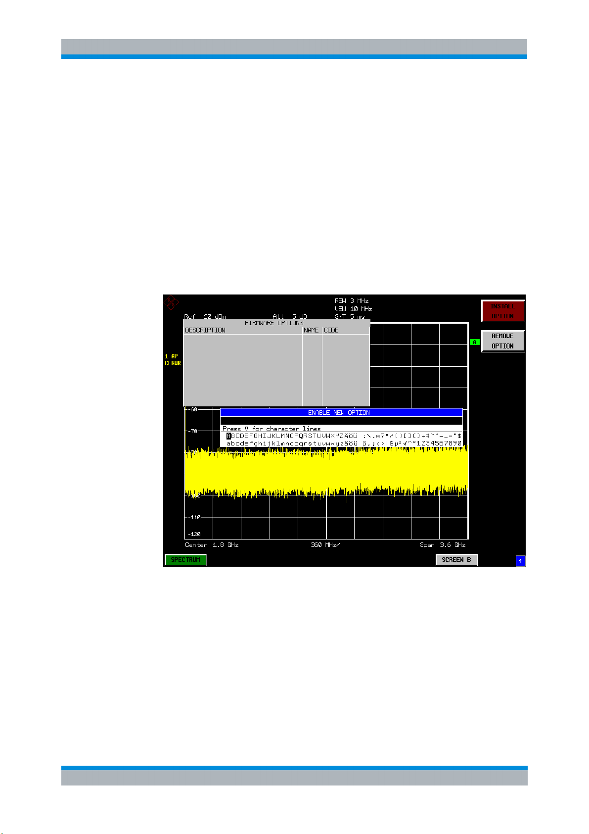
the OPTIONS softkey. A list of the options currently activated is displayed.
4. Press the INSTALL OPTION softkey. A Dialog is displayed allowing the option key
to be entered.
5. Enter the option key supplied with the R&S FS-K30 software.
6. When a valid option key has been supplied a dialog will be displayed explaining
that a reboot is required to complete this operation. Select OK in this dialog and
the instrument will be rebooted
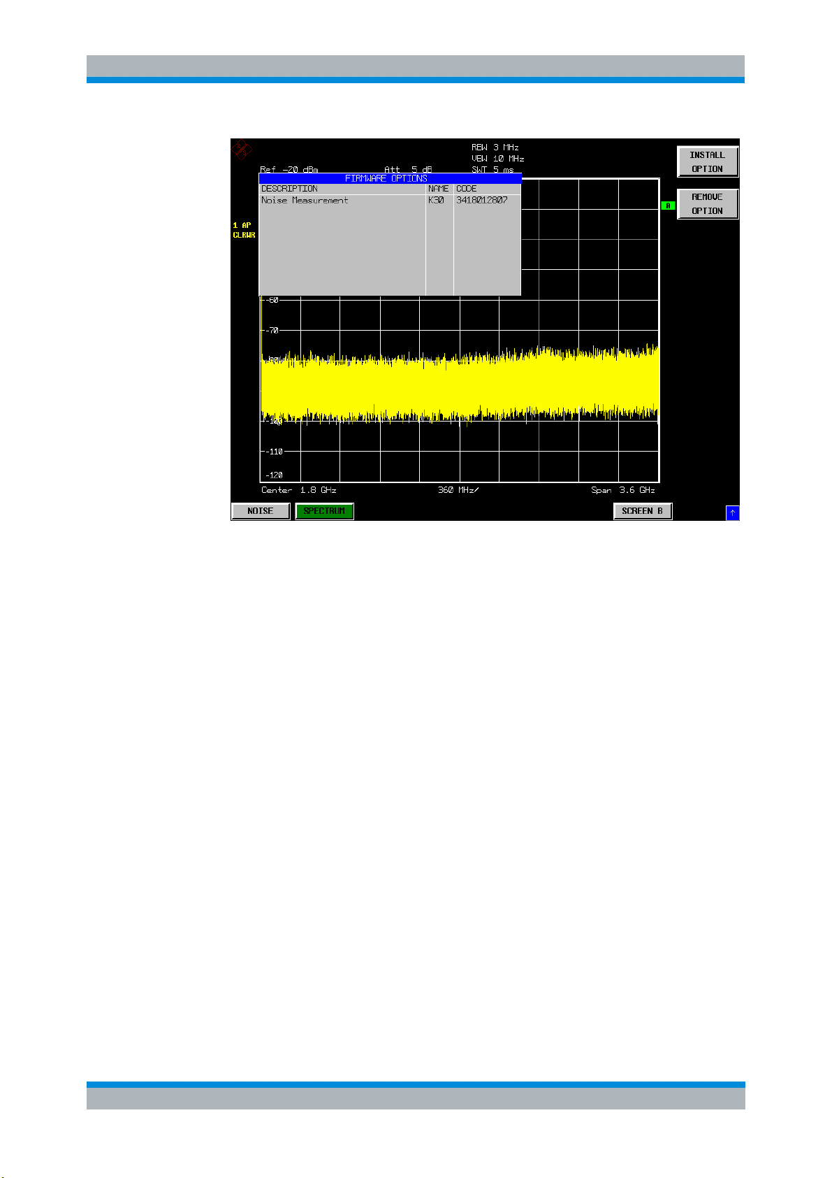
7. When the analyzer starts after the reboot a new hotkey will be displayed at the
bottom of the display labelled NOISE. In addition an entry for the R&S FS-K30
option will be displayed in the FIRMWARE OPTIONS dialog.
Software Manual 1300.6637.42 - 03 10
Page 27
&S
S-K30 General Information
R
F
Starting the application
1.3 Starting the application
Power up the R&S FSP, R&S FSU or R&S FSQ spectrum analyzer. When R&S FSK30 is correctly installed, there will be a hotkey labelled NOISE at the bottom of the
screen. Press the NOISE hotkey to start R&S FS-K30.
Note that if the spectrum analyzer is powered down whilst R&S FS-K30 is active, then
when the spectrum analyzer is powered up again it will start up in the R&S FS-K30
application. The application will start up with the same settings as those at the end of
the last measurement.
1.4 Exiting the application
To exit the R&S FS-K30 option, press the SPECTRUM hotkey at the bottom of the
screen. This will cause the option to exit and the spectrum analyzer to be activated
with the same settings as were set when the R&S FS-K30 option was activated.
Software Manual 1300.6637.42 - 03 11
Page 28
&S
S-K30 General Information
R
F
Quick Start Guide
1.5 Quick Start Guide
his section helps the user to quickly become familiar with R&S FS-K30 by working
T
step-by-step through an ordinary noise figure measurement. (Refer to section 2 for a
detailed reference guide.)
The gain and noise figure of an amplifier are to be determined in the range from 220
MHz to 320 MHz.
1.5.1 Setting up the measurement
1. Start the R&S FS-K30 application.
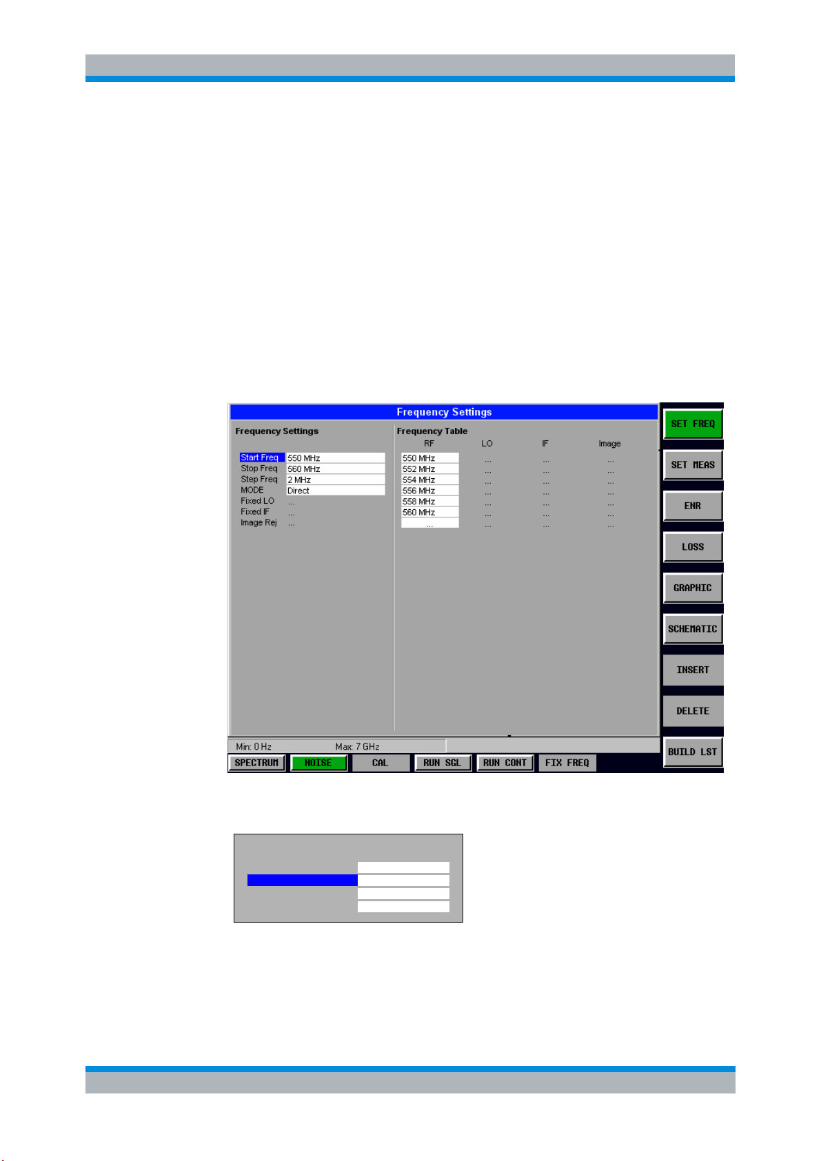
2. Press the SET FREQ softkey to open the Frequency Settings view.
3. Enter the desired frequency range in the Frequency Settings group of parameters. In
our example, enter a Start Frequency of 220 MHz and a Stop Frequency of 320 MHz.
Frequency Settings
Start Freq
Stop Freq
Step Freq
Mode
220 MHz
320 MHz
10 MHz
direct
4. Enter the desired Step Frequency size. In our example, 10 MHz should be entered.
Thus, a measurement is taken at 11 frequency points: 220 MHz, 230 MHz, 240 MHz,
..., 320 MHz.
Software Manual 1300.6637.42 - 03 12
Page 29
&S
S-K30 General Information
R
F
Quick Start Guide
The number of steps can be increased to up to 100 frequency points. This would,
of course, result in a correspondingly longer measurement time.
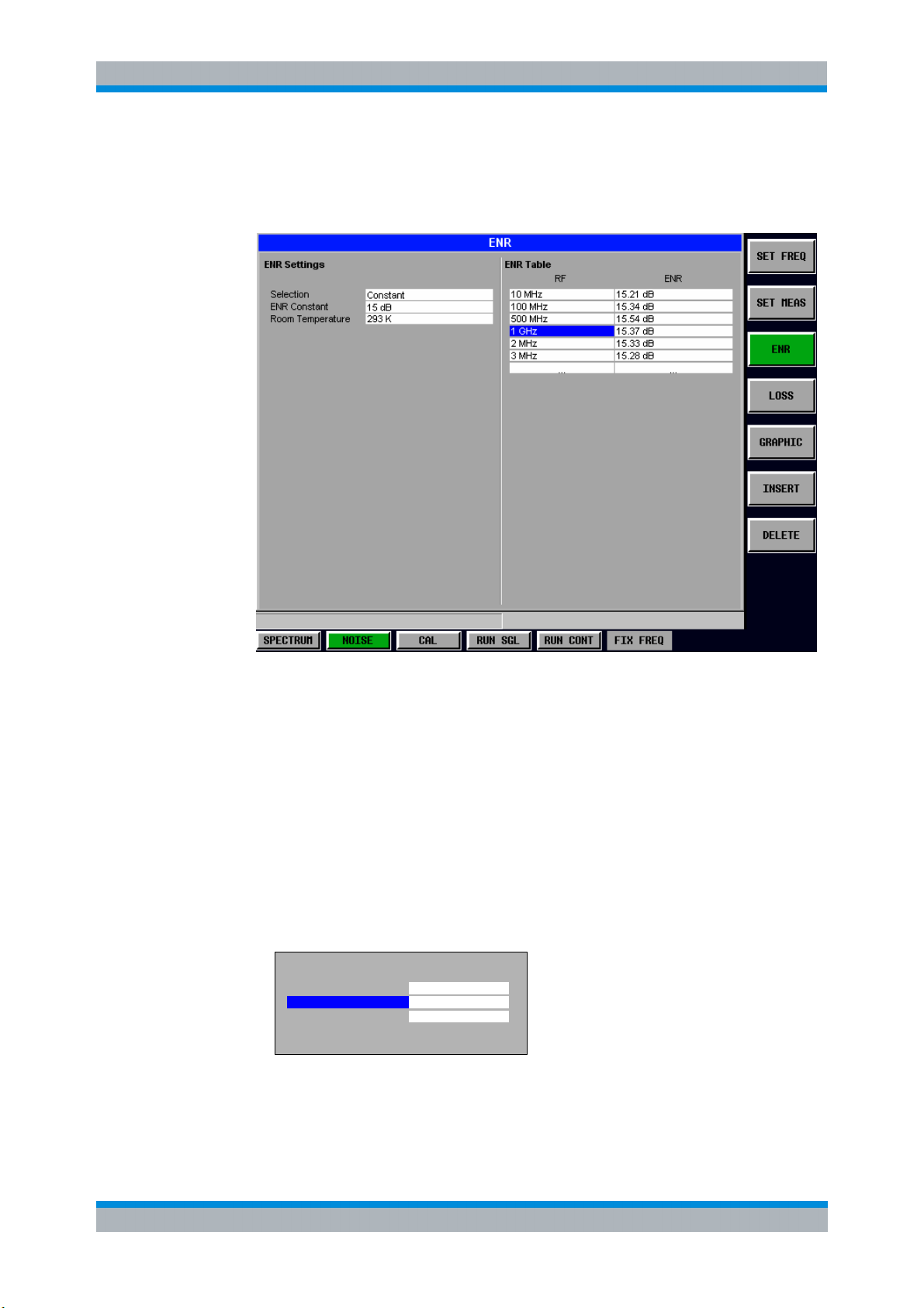
5. Press the ENR softkey to open the ENR Settings view
The default for the ENR value is 15 dB. The ENR value can either be entered as a
constant value that is valid for all frequencies (ENR Constant) or as a list of
frequency-dependent ENR values in the table on the right-hand-side of the ENR
Settings view.
For a noise source with a frequency-dependent ENR, sampled ENR values must
be entered for a number of different frequencies. The manufacturer of the noise
source supplies these sampled values.
For the purposes of this introduction to R&S FS-K30, it is sufficient to specify a
constant ENR value for this measurement. The default Selection for ENR is a
Constant value for all frequencies, so this does not need to be changed.
Enter the ENR
value that is valid for the measurement range of 220 MHz to 320
MHz in the ENR Constant field.
ENR Settings
Selection
ENR Constant
Room Temperature
Constant
15 dB
290 K
Software Manual 1300.6637.42 - 03 13
Page 30
&S
S-K30 General Information
R
F
Quick Start Guide
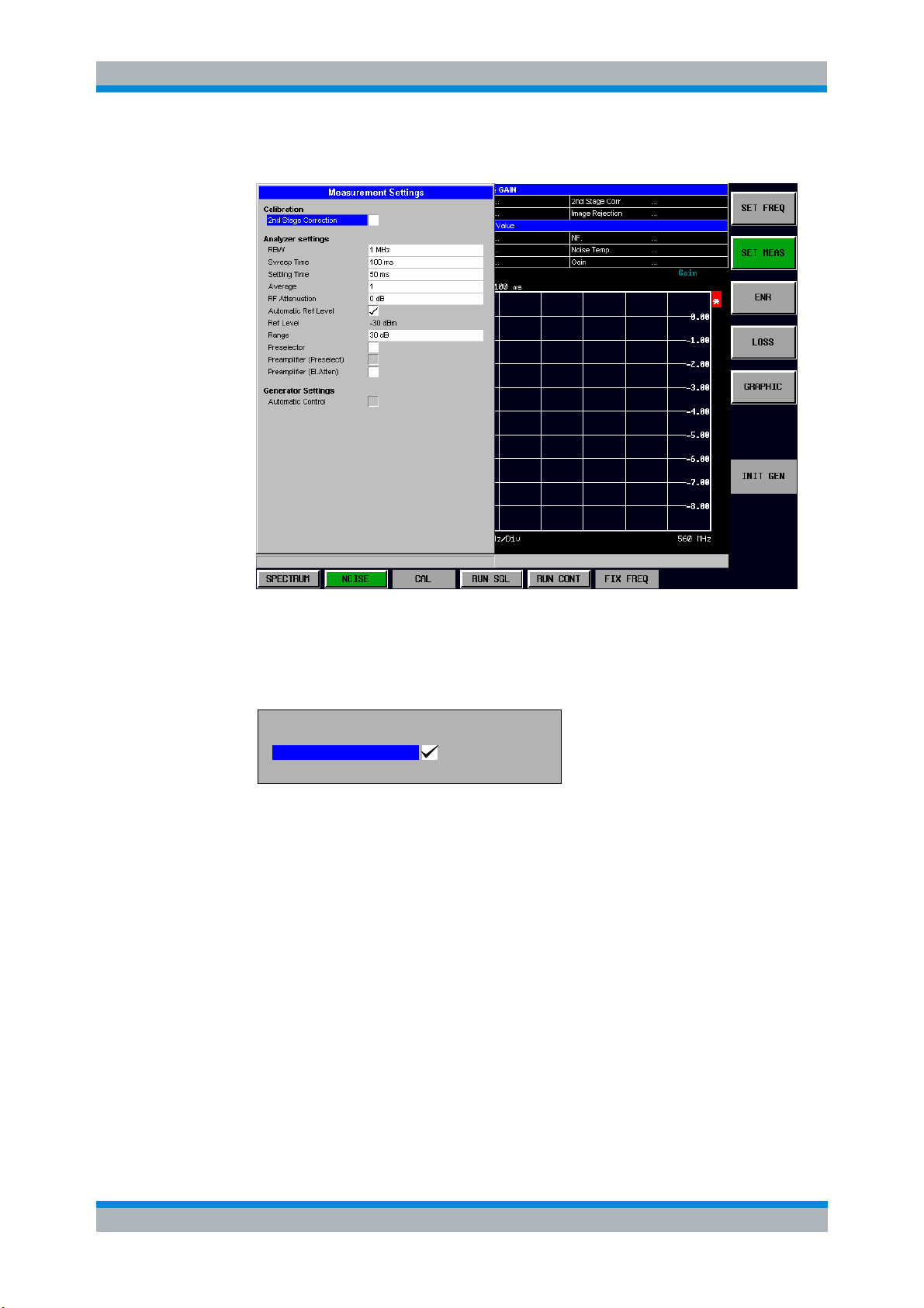
6. Press the SET MEAS softkey to open the Measurement Settings view
In order to perform measurements as accurately as possible the Second Stage
Correction field needs to be set. This specifies that a separate calibration
measurement is to be performed before the main measurement. The calibration
measurement allows the noise characteristics of the analyzer to be measured and
compensated for in the main measurement.
Calibration
Selection
2nd Stage Correction
7. Close the SET MEAS Settings view by pressing the NOISE hotkey.
1.5.1.1 Performing calibration
1. Connect the
2. Connect the
noise source to the RF input of the spectrum analyzer. (see Fig. 1)
supplied lowpass filter to the voltage supply input of the noise source.
Provide the voltage supply for the noise source by connecting it to the +28V socket of
the analyzer (labelled NOISE SOURCE on the instrument) via a coax cable and the
lowpass filter. The lowpass filter is connected between the noise source itself and the
NOISE SOURCE socket of the analyzer as shown.
The purpose of the lowpass filter is to suppress any interference (e.g. due to RF
interference), including interference from the supply line. This makes it possible to
perform very precise measurements.
Software Manual 1300.6637.42 - 03 14
Page 31

&S
S-K30 General Information
R
F
Quick Start Guide
Fig. 1 Preparation for calibration
1. Set the Second Stage Correction parameter in the Measurement Setting view to
ON. Calibration cannot be performed until this parameter is set.
2. Start
the calibration of R&S FS-K30 by pressing the CAL hotkey.
During calibration, the text "Running ..." is displayed in the Status Bar at the bottom
of the screen. The progress bar indicates the progress through the calibration
measurement.
After successful calibration, the Status Bar will display “Measurement Complete”
and the title bar at the top of the screen will show a CALIBRATED status on the
right-hand-side.
Note that this calibration measurement calibrates only the R&S FS-K30 application
and not the spectrum analyzer itself.
1.5.2 Performing the amplifier measurement
After calibration has been successfully completed, insert the DUT (in this example, the
amplifier) into the test setup between the noise source and RF Input of the spectrum
analyzer. (see Fig. 2)
Noise Source +28V
RF
Low pass Noise Source
0V
+28V
Fig. 2 Test Setup
DUT
Software Manual 1300.6637.42 - 03 15
Page 32

&S
S-K30 General Information
R
F
Navigation
1. Start the measurement by pressing the RUN SGL hotkey.
During the measurement, the text "Running..." is displayed in the Status Bar at the
bottom of the screen. The progress bar indicates the progress through the
measurement.
Measurement results are updated as the measurement is in progress. The results are
isplayed in graphical form. There are two traces, one for Noise Figure/Temperature
d
and one for the Gain of the DUT. The display can be toggled to a tabular list of
measurement points by pressing the DISPLAY softkey.
1.6 Navigation
This section deals with navigation within the option. Navigation here is taken to mean
all forms of interaction with the option except for remote control. The different methods
of interacting with the option are:
I Hotkeys
I Softkeys
I Hardkeys
I Numeric Keypad
I Roll-key
I Cursor Keys
I External Keyboard
I Mouse
1.6.1 Hotkeys
Hotkeys are allocated to the seven keys at the bottom edge of the screen. On initial
start-up of the K30 option, the hotkeys provided are shown in Fig. 3. These hotkeys are
present at all times once the option has been started.
Fig. 3 Initial Hotkey menu
A keystroke activates the associated hotkey. An activated hotkey changes colour to
green, as shown.
CAL CAL
RUN SGL RUN CONTCALNOISESPECTRUM FIX FREQ
Software Manual 1300.6637.42 - 03 16
Page 33

&S
S-K30 General Information
R
F
Navigation
These hotkeys perform the following operations:
SPECTRUM
NOISE
CAL
RUN SGL
The SPECTRUM hotkey exits the R&S FS-K30 option & returns to the spectrum
analyzer with all previous settings restored.
The NOISE hotkey returns the user to the home screen of K30, where measurement
results can be seen. All settings views and dialogs are removed from the display, and
the default softkey menu is displayed.
The NOISE hotkey remains green whenever R&S FS-K30 is active.
The CAL hotkey starts a calibration measurement.
If another measurement is running, such as frequency range or a fixed frequency
measurement, the running measurement will be aborted before the calibration
measurement is started.
Pressing the CAL hotkey whilst a calibration measurement is running causes the
measurement to be stopped (aborted).
The RUN SGL hotkey starts a fixed frequency range measurement.
If another measurement is running, such as Calibration or a fixed frequency
measurement, the running measurement will be aborted before the single frequency
range measurement is started.
RUN CONT
FIX FREQ
Pressing the RUN SGL hotkey whilst a single frequency range measurement is
running causes the measurement to be stopped (aborted).
The RUN CONT hotkey starts a continuous frequency range measurement.
If another measurement is running, such as Calibration or a fixed frequency
measurement, the running measurement will be aborted before the continuous
frequency range measurement is started.
Pressing the RUN CONT hotkey whilst a continuous frequency range measurement is
running causes the measurement to be stopped (aborted).
The FIX FREQ hotkey starts a fixed frequency measurement.
If another measurement is running, such as Calibration or a frequency range
measurement, the running measurement will be aborted before the fixed frequency
measurement is started.
Pressing the FIX FREQ hotkey whilst a fixed frequency measurement is running
causes the measurement to be stopped (aborted).
The FIX FREQ hotkey is only available when results are displayed in tabular form and
a valid result is selected in the table of results.
Software Manual 1300.6637.42 - 03 17
Page 34

&S
S-K30 General Information
R
F
Navigation
1.6.2 Softkeys
1.6.2.1 Settings Softkeys
The softkeys are assigned to the nine keys on the right-hand side of the display. These
enable quick access to all of the parameter settings of the K30 option. Each of the top
five softkeys, when pressed, brings up a settings view for a group of parameters.
These softkeys are always available (except for when editing limit lines or trace
memories and when using Save Recall / print manager ) and are as follows:
SET FREQ
SET MEAS
ENR
LOSS
GRAPHIC
Fig. 4 Main softkeys
Frequency settings
measurement mode & schematic display
Measurement settings
generator settings
ENR settings
Loss settings
& list)
Graphic settings
- measurement frequencies,
- calibration, analyser &
- constant & list
- Loss Input & Loss Output (constant
- trace settings
Each of these groups of settings is described in detail in the Measurements & Settings
section of this manual.
Software Manual 1300.6637.42 - 03 18
Page 35

&S
S-K30 General Information
R
F
Navigation
1.6.2.2 Other Softkeys
All other softkeys have different functions depending on the instrument state.
Therefore, the labels (text) on the softkeys will vary to reflect their current function. The
state of the softkeys is indicated by different appearances and colours, as follows:
SOFTKEY
LABEL 1
SOFTKEY
LABEL 2
SOFTKEY
LABEL 3
SOFTKEY
LABEL 4
SOFTKEY
LABEL 5
SOFTKEY
LABEL 6
SOFTKEY
LABEL 7
SOFTKEY 8
VAL1
VAL2
Fig. 5 Setup of the softkey area
Softkey available (normal state)
Softkey active (green)
Softkey active and dialog
displayed (red)
No softkey available
Softkey disabled => function not available
(without 3D Frame)
Toggle softkey (current value of parameter
highlighted in green)
A softkey in its normal state, where its function is available, is coloured grey with a 3D
border.
A softkey that is disabled, because its function is not
available, is coloured grey without
a 3D border. Softkeys may become disabled because of the state of the instrument or
because other settings disable the function associated with the softkey.
An active softkey (highlighted in green) is used when the softkey selects an item or
view. For example, the SCHEMATIC softkey will be highlighted green when the
schematic is displayed
A toggle softkey is used to change the value of a parameter that has only two states.
Each press of the softkey toggles the value of the parameter. The current parameter
value is highlighted in green in the lower half of the softkey label. For example, in the
measurement results view, the DISPLAY softkey will have either LIST or GRAPH
highlighted in green depending on whether the results are currently displayed as a list
of measurement points or graphical trace(s).
When no function is assigned to a softkey then no softkey label will be shown.
Software Manual 1300.6637.42 - 03 19
Page 36

&S
S-K30 General Information
R
F
Navigation
1.6.3 Hardkeys
Hardkeys allow quick access to the desired parameter and various functions. The
hardkeys supported by the R&S FS-K30 option are as follows (other hardkeys do
nothing):
FREQ Hardkey When the FREQ hardkey is pressed the General Settings view is displayed (if it is not
already being displayed) and the Frequency parameter is selected.
AMPT Hardkey When the AMPT hardkey is pressed the General Settings view is displayed (if it is not
already being displayed) and the relevant Signal Level parameter for the selected
signal input is selected.
MKR Hardkey When the MKR hardkey is pressed the main Marker softkey menu is displayed (if it is
not already being displayed).
MKR-> Hardkey When the MKR-> hardkey is pressed the Marker extension softkey menu is displayed
(if it is not already being displayed).
SWEEP Hardkey When the SWEEP hardkey is pressed the General Settings view is displayed (if it is not
already being displayed) and the Capture Time parameter is selected.
MEAS Hardkey When the MEAS hardkey is pressed the Main softkey menu is displayed (if it is not
already being displayed).
TRACE Hardkey When the TRACE hardkey is pressed the General Settings view is displayed (if it is not
already being displayed) and the Burst Count parameter is selected.
DISP Hardkey When the DISP hardkey is pressed the Display softkey menu is displayed (if it is not
already being displayed).
FILE Hardkey When the FILE hardkey is pressed, the Save & Recall softkey menu is displayed,
allowing the save & recall of settings and/or measurement results of the K90 option.
PRESET Hardkey When the PRESET hardkey is pressed the K90 option is exited and a preset will be
performed. Note that all options (including R&S FSP-K90) shall also be preset.
HCOPY Hardkey When the HCOPY hardkey is pressed the print manager softkey menu is displayed,
allowing selection of the items to be printed.
Software Manual 1300.6637.42 - 03 20
Page 37

&S
S-K30 General Information
R
F
Navigation
1.6.4 External Keyboard
The external keyboard is optional. The keys on the external keyboard that can be used
to interact with the K30 option are as follows:
Number keys 0 to 9
Decimal point (“.”) Inserts a decimal point “.” at the cursor position.
Minus key (“-“) Changes the sign of the mantissa or exponent of a numeric parameter. A “-“ is
ESC key Aborts the entry before it has been terminated. The previous value is restored.
ENTER key Terminates the input of dimension quantities. The new value is set.
Left and Right Cursor
Keys are used to:
Up and Down Cursor
keys are used to:
CTRL keys Used to activate hotkeys. Each of the seven hotkeys is allocated a different function
inserted at the cursor position in the case of an alphanumeric parameter.
Closes the entry field after termination of input.
Closes pop-up dialogs.
Invokes the input of parameters or immediately sets the new value.
Selects the highlighted item in drop-down menus.
Navigate between individual parameters within the setting views and some of the
pop-up dialogs.
Navigate between the individual items within drop-down menus.
Move the cursor left & right inside the entry window to reach a particular position in
the string during alphanumeric entry.
Navigate between individual parameters within the setting views and some of the
pop-up dialogs.
Navigate between the individual items within drop-down menus.
Increment or decrement the value of a parameter during numeric entry.
(F) key. To access these hotkeys press CTRL and the corresponding F key together
(see Fig. 6):
CTRL + F1 CTRL + F2 CTRL + F3 CTRL + F4 CTRL + F5 CTRL + F7
AUTO LVLNOISESPECTRUM
RUN CONT
SCREEN BRUN SGL
Fig. 6 Quick Access to Hotkeys
Function Keys
Used to activate softkeys. Each of the nine softkeys is allocated a different function (F)
key. To access these softkeys the corresponding F key, as shown below:
F1
F2
F3
F4
F5
F6
F7
F8
F9
Fig. 7 Quick access to softkeys
SOFTKEY 1
SOFTKEY 2
SOFTKEY 3
SOFTKEY 4
SOFTKEY 5
SOFTKEY 6
SOFTKEY 7
SOFTKEY 8
SOFTKEY 9
Software Manual 1300.6637.42 - 03 21
Page 38

&S
S-K30 General Information
R
F
Navigation
1.6.5 Mouse
The mouse can be used to select individual parameters within the settings views or
data entry dialogs and to activate hotkeys and softkeys. It can also be used to select
values from a drop-down list.
1.6.6 Selecting & Editing Parameters
Parameters are set either by numeric or alphanumeric entry or by simple selection
from a list of possible values (a drop-down list is used to select an “enumerated” value)
or by using checkboxes to turn a parameter setting on and off.
In all cases, the parameter has to be selected by placing focus on it and then editing
has to be enabled before its value can be changed.
The rollkey and cursor keys on the front panel are provided for navigation and
selection of parameters.
The numeric keypad, rollkey and cursor keys on the front panel and an external
keyboard (optional) are provided for the entry of parameter values.
1.6.6.1 Numeric Keypad
89
7
4
56
12
0
.
ESC
CANCEL
ENTER
OK
GHz
-dBm
MHz
dBm
kHz
3
Hz
-
dB..
BACK
The numeric keypad is provided for entry of numeric parameters. It contains the
following keys:
I Number keys 0 to 9
Starts editing of the selected parameter. This enables a new value to be entered for
a parameter directly without having to press ENTER first. The digit will be
displayed as the first digit of the newly entered value.
Inserts a digit at the cursor position when editing an alphanumeric parameter.
I Decimal point
Inserts a decimal point “.” at the cursor position.
I Sign key (“-“)
Changes the sign of the mantissa or exponent of a numeric parameter. A “-“ is
inserted at the cursor position when editing an alphanumeric parameter.
I Unit keys (GHz/-dBm, MHz/dBm, kHz/dB and Hz/dB)
s
V
ms
mV
mV
?
s
?V
dB
ns
nV
Software Manual 1300.6637.42 - 03 22
Page 39

&S
S-K30 General Information
R
F
Navigation
I Provides the numeric value entered with the selected unit and sets the parameter
to that value.
The unit keys are all assigned the value “1” for dimensionless quantities or for level
entries (e.g. in dB). The unit keys thus assume the function of an ENTER key.
I BACK key
Deletes the character to the left of the cursor with alphanumeric entry.
ESC/CANCEL key
I
Aborts the entry of a new parameter value. The previous value is restored.
I Closes pop-up dialogs.
I ENTER key
Enables editing of the selected parameter (using numeric keys or rollkey).
Finishes the editing of a parameter value. The new value is set.
For an alphanumeric value, the new value is set to that displayed (using the
current unit if applicable).
I In a drop-down menu, the parameter is set to the currently selected value in the
list.
1.6.6.2 Rollkey
The rollkey has various functions:
• In a settings view, the rollkey can be used to navigate between individual
parameters (the parameter selected being highlighted).
• In drop-down menus, the rollkey can be used to navigate between the individual
values for the parameter.
• During numeric entry, the parameter is incremented (by turning clockwise) or
decremented (by turning counter-clockwise) at a defined step size (depending on
the parameter).
• In setting views and data entry dialogs pressing the rollkey invokes the input of
parameters or immediately sets the new value, i.e. pressing the rollkey is like
pressing the ENTER key.
• In drop-down menus, pressing the rollkey selects the relevant item.
Software Manual 1300.6637.42 - 03 23
Page 40

&S
S-K30 General Information
R
F
Navigation
1.6.6.3 Cursor Keys
The keys
and are used to:
I Navigate between individual parameters within the setting views and some of the
pop-up dialogs.
I Navigate between the individual values within drop-down menus.
I Move the cursor left & right inside the entry window to reach a particular position in
the string during alphanumeric entry.
The keys
and are used to:
I Navigate between individual parameters within the setting views and some of the
pop-up dialogs.
I Navigate between the individual items within drop-down menus.
I Increment or decrement the value of a parameter during numeric entry.
1.6.6.4 Selection of a parameter within a settings view
Selection using rollkey
1. Press SET FREQ softkey for example (Frequency settings view is displayed).
2. Rotate the rollkey until reaching the required parameter.
Turning the rollkey clockwise selects parameters in the upward direction, turning it
counter-clockwise selects parameters in the downward direction.
Example: Selecting Image Rejection (Frequency settings)
Image Rejection 0 dB
When the Image Rejection parameter is selected its label is highlighted blue.
When the desired parameter is reached press the rollkey to edit the parameter.
Software Manual 1300.6637.42 - 03 24
Page 41

Fixed LO, IF = RF + LO
ll the
&S
S-K30 General Information
R
F
Navigation
Selection using cursor keys
1. Cursor
, , or until obtaining the required parameter.
Within a list of parameters, the Down and Right both move to the next item (down)
in the list and the Up and Left keys both move to the previous item (up) in the list.
Within a table of parameters, the cursor keys move the cursor in the direction
indicated.
2. To start editing the parameter, either press the ENTER key on the numeric keypad,
or press the rollkey.
3. For numeric parameters, editing can also be started by entering the new value
directly from the numeric keypad without pressing the ENTER key first.
Example: Selecting Mode (Frequency settings)
irect
Direct
Fixed IF, LO = RF + IF
Fixed IF, LO = abs(RF - IF)
ENTER
OK
Mode D
Mode Direct
When ENTER is pressed, a drop-down menu is displayed, which contains a
available settings to which the Mode parameter can be set.
Selection using mouse
1. Use the mouse to move the cursor to the parameter and press the left mouse
button to select the parameter.
2. To start editing the parameter, either press the ENTER key on the numeric keypad,
or press the rollkey.
For numeric parameters, editing can also be started by entering the new value
directly from the numeric keypad without pressing the ENTER key first.
Selection using external keyboard
1. Select parameter using the cursor keys (in the same way as using the cursor keys
on the front panel).
2. To start editing the parameter, either press the ENTER key on the numeric keypad,
or press the rollkey.
For numeric parameters, editing can also be started by entering the new value
directly from the numeric keypad without pressing the ENTER key first.
Software Manual 1300.6637.42 - 03 25
Page 42

The parameter is not set to the new value until either one of the unit keys on the
No other keys need to
&S
S-K30 General Information
R
F
Navigation
Entry of a numeric value
Once a parameter has been selected (see above), a new value for a numeric
parameter can be entered in a number of ways. With the exception of entry via the
number keys, to start editing the parameter, either press the ENTER key on the
numeric keypad, or press the rollkey before following the instructions below.
f an error occurs, for example, the entered value is out of range, then the new value
I
will not be accepted for the parameter setting.
Entry using number keys (numeric keypad)
N Enter required value using the number keys.
Example: To enter 200 MHz
2
0
0
MHz
dBm
IF Frequency 200 MHz
numeric keypad, the ENTER or the rollkey is pressed.
If ststhe new value is not valid, then a message box is displayed and the entered
value will be replaced with a valid value. For example, when a value above the
maximum allowed is entered, then the maximum value allowed will be shown in the
entry box. The parameter will still be ready for editing so that another value can be
entered if desired.
Entry using cursor keys
N Cursor
or until obtaining the required value.
The application prevents the minimum and maximum values of the parameter from
being exceeded and displays an “Out of range“ message box if attempted.
N.B The cursor keys increment/decrement a parameter value in large steps.
Example: Cursor down to 100MHz
IF Frequency 100 MHz
Each change of the parameter value takes place immediately.
be pressed.
Software Manual 1300.6637.42 - 03 26
Page 43

her keys need to
not close automatically. They can be closed by
&S
S-K30 General Information
R
F
Navigation
Entry using rollkey
1. Rotate the rollkey until reaching the required value.
2. Turning the rollkey clockwise increases the value, turning it counter clockwise
decreases the value.
The application prevents the minimum and maximum values of the parameter from
being exceeded and displays an “Out of range“ message box if attempted.
N.B The rollkeys increment/decrement a parameter value in small steps.
Example: Rotate to 200MHz
IF Frequency 200 MHz
Each change of the parameter value takes place immediately. No ot
be pressed.
Entry using external keyboard
N Enter value using number keys 0 – 9 in the same way as for using the number
keys on the numeric keypad (see above).
Terminating the entry
1. Press one of the unit keys on the numeric keypad.
The unit is entered in the parameter’s edit box and the new parameter value is set
immediately.
2. Press the ENTER key (on numeric keypad or external keyboard) or press the
rollkey.
The new parameter value is set immediately.
Pop-up dialogs, where used, do
pressing the ESC key.
In both cases, if the new value is not valid, then a message box is displayed and the
entered value will be replaced with a valid value. For example, when a value above the
maximum allowed is entered, then the maximum value allowed will be shown in the
entry box. The parameter will still be ready for editing so that another value can be
entered if desired.
Software Manual 1300.6637.42 - 03 27
Page 44

down menu is displayed, which
&S
S-K30 General Information
R
F
Navigation
Correcting the entry
1. Position the cursor to the right of the digit which is to be deleted using the cursor
keys
or .
2. Press the BACK key. The digit to the left of the cursor is deleted.
3. Enter new digits. Each digit is inserted to the left of the cursor, the other digits are
shifted right.
Aborting the entry
1. Press the ESC key during parameter editing.
The original parameter value is restored. The new entry is deleted.
2. If a pop-up dialog is displayed, press the ESC key again.
The entry window is closed, the original value remains active.
1.6.6.5 Entry of an enumerated value
Once a parameter has been selected (see above), a new value for an enumerated
parameter can be entered in a number of ways. To start editing the parameter, either
press the ENTER key on the numeric keypad, press the rollkey or left click with the
mouse on the drop down button before following the instructions below.
When the rollkey or ENTER is pressed, a dropcontains all the available settings that may be selected for the parameter.
Selection of setting using cursor keys
1. Cursor
or
until obtaining the required setting.
2. Press ENTER on external keyboard or numeric keypad, or press rollkey to select
the desired setting of parameter.
Currently selected setting of the parameter is highlighted blue.
Pressing ENTER sets the new setting of the parameter immediately.
Selection of setting using rollkey
1. Rotate the rollkey until reaching the required setting.
2. Press rollkey to select setting.
Currently selected setting of the parameter is highlighted blue.
Pressing the rollkey sets the new setting of the parameter immediately.
Software Manual 1300.6637.42 - 03 28
Example: Select Mode parameter.
Page 45

&S
S-K30 General Information
R
F
Navigation
Selection of setting using mouse
N When the parameter is selected and ready for editing, select a new setting using
the mouse by left-clicking on the new setting from the drop-down list. The new
setting of the parameter is set immediately.
Selection of setting using external keyboard
1. Select setting using cursor keys.
2. Press ENTER to set the parameter to the new value.
1.6.6.6 Entry of a checkbox
A checkbox is used for parameter settings that are either On or Off (Boolean settings).
A checkmark () appears in the box when the setting is On; the checkbox is empty
when the setting is Off.
Once a parameter has been selected (see above), a new value for a Boolean
parameter can be entered in a number of ways. Because Boolean parameters are very
simple, it is not necessary to press the ENTER key on the numeric keypad or to press
the rollkey in order to edit them.
Toggle between the two states of a checkbox using rollkey
3. Press the rollkey to toggle between the two states.
Example: Turn 2nd Stage Correction setting to Off
press
ENTER
OK
2nd Stage Correction
The checkbox is empty when the settings is Off.
Toggle between the two states of a checkbox using numeric keypad
4. Press the ENTER key to toggle between the two states.
Example: Turn 2nd Stage Correction setting to On
ENTER
OK
2nd Stage Correction
Toggle between the two states of a checkbox using a mouse
N Left-click on the checkbox to toggle between the two states.
Software Manual 1300.6637.42 - 03 29
Page 46

560 MHz
10 MHz
570 MHz
580 MHz
Frequency Table
&S
S-K30 General Information
R
F
Navigation
Toggle between the two states of a checkbox using external keyboard
N Press ENTER to toggle between the two states.
1.6.6.7 Table Navigation
n R&S FS-K30 some of the settings views contain tables of data (for example the
I
frequency table in the Frequency Settings view). Initially when navigating through the
settings in a view only the header of a table can be selected
Selecting & Editting parameters in a table
1. Select the table header using the rollkey or cursor keys
requency Table
F
RF LO IF Image
50 MHz10 MHz
5
552 MHz 10 MHz 562 MHz
554 MHz 10 MHz 564 MHz
56 MHz10 MHz
5
558 MHz 10 MHz 568 MHz
560 MHz 10 MHz 570 MHz
..
.
.
60 MHz
5
66 MHz
5
..
.
70 MHz
5
572 MHz
574 MHz
76 MHz
5
578 MHz
580 MHz
..
..
.
2. Press rollkey or the ENTER key to select the first field in the table
RF LO IF Image
550 MHz 10 MHz 560 MHz
552 MHz 10 MHz 562 MHz
554 MHz 10 MHz 564 MHz
556 MHz 10 MHz 566 MHz
558 MHz 10 MHz 568 MHz
570 MHz
572 MHz
574 MHz
576 MHz
578 MHz
3. The fields in the table can now be navigated around and edited in the same ways
as the other settings in the view.
4. Once the required changes have been made in the table press the ESC key to exit
the table.
5. The table heading will be highlighted once more
ESC
CANCEL
CANNEL
Frequency Table
RF LO IF Image
550 MHz 10 MHz 560 MHz
552 MHz 10 MHz 562 MHz
554 MHz 10 MHz 564 MHz
556 MHz 10 MHz 566 MHz
558 MHz 10 MHz 568 MHz
560 MHz 10 MHz 570 MHz
... ... ...
570 MHz
572 MHz
574 MHz
576 MHz
578 MHz
580 MHz
...
Software Manual 1300.6637.42 - 03 30
Page 47

&S
S-K30 General Information
R
F
Navigation
1.6.7 Status Bar & Title Bar
1.6.7.1 Title Bar
The title bar is visible at the very top of the display when R&S FS-K30 is active and no
settings views are displayed.
Fig. 8 Title Bar
The centre of the title bar shows the name of the active application. For R&S FS-K30,
this is “NOISE & GAIN”.
On the left of the title bar, the current measurement mode (frequency list calculation
mode) is displayed.
On the right of the title bar, the calibration status of R&S FS-K30 is displayed. Note that
“CALIBRATED” means that R&S FS-K30 is calibrated and does not indicate whether
the spectrum analyzer itself is calibrated or not. The calibration status of R&S FS-K30
is only displayed when second stage correction is switched on, because the calibration
status of the option is not taken into account in measurements when the second stage
correction is switched off.
1.6.7.2 Status Bar
The main status bar is displayed at the bottom of the display, just above the hotkeys.
When a parameter in a settings view is selected, the status bar will display the
minimum and maximum, settings for the selected parameter (see Fig. 9).
MIN:<XX.XX> MAX:<XX.XX>
Fig. 9 Status Bar
When a parameter whose value is enumerated or Boolean in type is selected in any
dialog, the status bar will show “N/A“ displayed for the minimum and maximum, since
the minimum and maximum values are “Not Applicable.”
At other times, the status bar shows the current measurement status along with
detailed information about the progress through any running measurement.
The status bar is also used to display warning and error messages to the user. In order
to highlight these messages, warning messages are displayed with a blue background
and error messages with a red background. Refer to Section 1 for a list of warning and
error messages.
Software Manual 1300.6637.42 - 03 31
Page 48

&S
S-K30 General Information
R
F
Save/Recall
1.7 Save/Recall
This section of the user manual describes the Save/Recall facility of the option.
FILE
he FILE hardkey brings up the Save/Recall softkey menu. Any settings views on
T
display when the save/recall softkey menu is displayed shall be closed.
Figure 10 Save/Recall softkey menu
The save/recall facility provided by R&S FS-K30 is exactly the same as that provided
by the host analyser. Refer to the user manual for the spectrum analyser for details of
the save/recall facility operation.
The save/recall facility in R&S FS-K30 provides the following items that can be saved
and/or recalled:
I Current Settings – All user settings provided by R&S FS-K30
I All Limit Lines – Noise & Gain limit lines
I All Traces – The current set of measurement results.
I ENR - All data entered in the ENR Settings view.
I Loss Settings - All loss input & output data from the Loss settings view.
N.B. Items in bold are items also available in the Spectrum Analyzer.
To close the save/recall softkey menu and return to the main R&S FS-K30 softkey
menu, press the NOISE hotkey.
Software Manual 1300.6637.42 - 03 32
Page 49

&S
S-K30 General Information
R
F
Printing
1.8 Printing
his section of the user manual describes print facility of the option
T
The HCOPY hardkey brings up the print softkey menu. Any settings views on display
when the print softkey menu is displayed shall be closed.
Fig. 11: Print softkey menu
The print facility provided by FS-K30 is exactly the same as that provided by the host
analyser. Refer to the user manual for the spectrum analyser for details of the print
facility operation.
To close the print softkey menu and return to the main R&S FS-K30 softkey menu,
press the NOISE hotkey.
Software Manual 1300.6637.42 - 03 33
Page 50

&S
S-K30 General Information
R
F
Limit Line
1.9 Limit Line
This section of the user manual describes limit line facility of the option.
The LINES hardkey brings up Limit Line selection view and softkey menu. Any settings
views on display when the limit lines selection view is displayed shall be closed.
Fig. 12 Limit Line selection view
From the Limit Line selection view it is possible to add new limit lines, edit existing limit
lines, delete limit lines and enable/disable the display of limit lines.
Software Manual 1300.6637.42 - 03 34
Page 51

&S
S-K30 General Information
R
F
Limit Line
1.9.1 Adding Limit Lines
New limit lines can be defined by pressing the NEW softkey from the limit line selection
softkey menu.
The NEW softkey allows a new limit line to be defined. After pressing the NEW softkey
the limit line selection view will be replaced with the limit line data view.
Fig. 13 Limit Line data view (for a new limit line)
Once the limit line data has been entered as required, press the SAVE softkey to save
the changes. Pressing the ESC hardkey will display a prompt requesting whether the
limit line data should be stored or not. Select the appropriate response with the cursor
keys or rollkey and hit ENTER or press the rollkey to perform the selected action.
1.9.1.1 Name
The Name field allows each limit line to be uniquely identified. The name can contain
any combination of number, letters and characters.
Each limit line must have a unique name. An error message will be displayed if a new
limit line is added with the same name as an existing limit line.
Pressing the NAME softkey will cause the Name field to be selected.
Software Manual 1300.6637.42 - 03 35
Page 52

&S
S-K30 General Information
R
F
Limit Line
1.9.1.2 Limit
The Limit field specifies the type of result that this limit line applies to (Noise or Gain)
a n d t h e t yp e o f l i m i t t h a t s ho u l d b e a p p l i e d ( Up p e r o r L o we r ) .
1.9.1.3 Comment
The Comment field allows the user to attach a textual description to a limit line. The comment
can contain any combination of number, letters and characters.
1.9.1.4 Frequency / Limit Table
The Frequency/Limit Table lists the Limit values for different Receive Frequency (RF)
values. R&S FS-K30 will interpolate between points in the list for RF values used in a
measurement that are not explicitly entered in the Frequency/Limit list.
When focus is moved to the Frequency/Limit Table at the bottom left of the view, the
current parameter in the table is highlighted. Navigation through the table is possible in
all four directions using the cursor keys.
It is possible to add individual values directly into the Frequency/Limit Table, including
insertion and deletion of RF/Limit value pairs (rows in the list). The list can contain up
to 100 RF/Limit value pairs. Note that the order of RF values must be in ascending
sequence.
Fig. 14 Frequency/Limit table
INSERT
The INSERT softkey inserts a new row in the Limit Table directly above the row
currently selected. The cursor will be moved to the corresponding column in the new
row ready for detailed entry. The INSERT softkey shall be disabled when the maximum
number of entries in the Limit Table has been reached.
Fig. 15 Inseting limit line data
Software Manual 1300.6637.42 - 03 36
Page 53

&S
S-K30 General Information
R
F
Limit Line
DELETE
The DELETE softkey deletes the currently selected row in the Limit Table. Note that no
confirmation is required for this action. The cursor will be moved to the corresponding
column in the next row.
1.9.2 Modifying Limit Lines
Existing limit lines can be modified by pressing the EDIT softkey from the limit line
selection softkey menu
EDIT
The EDIT softkey allows the limit line selected in the limit line selection view to be
modified. After pressing the EDIT softkey the limit line selection view will be replaced
with the limit line data view containing the limit line data for the selected limit line.
Fig. 16 Limit Line data view (for an existing limit line)
Once the limit line data has been modified as required, press the SAVE softkey to save
the changes. Pressing the ESC hardkey will display a prompt requesting whether the
changes to the limit line data should be stored or not. Select the appropriate response
with the cursor keys or scroll key and hit ENTER or press the rollkey to perform the
selected action.
Software Manual 1300.6637.42 - 03 37
Page 54

&S
S-K30 General Information
R
F
Limit Line
1.9.3 Deleting Limit Lines
Existing limit lines can be deleted by pressing the DELETE softkey from the limit line
selection softkey menu
The DELETE softkey allows the limit line selected in the limit line selection view to be
deleted.
1.9.4 Enabling / disabling Limit Lines
Limit lines can be enabled and disabled. When a limit line is enabled it will be
displayed in the relevant results graph, and limit checking will be performed. When a
limit line is disabled it will not be displayed and no limit checking for this line will be
performed.
To enable/disable a limit line select the required limit line in the limit line selection view.
When the required limit line is highlighted press the ENTER key or press the rollkey to
toggle the state of the limit line between enabled and disabled. When a limit line is
enabled a symbol is shown in the Enabled field. Note that only one limit line of each
type can be active at a given time.
Fig. 17 Enabling/Disabling limit lines using the Limit line selection view
Software Manual 1300.6637.42 - 03 38
Page 55

&S
S-K30 General Information
R
F
Trace Menu
1.10 Trace Menu
This section of the user manual describes the Trace Memory facility. The trace
memory facility is accessed by its own softkey menu.
TRACE
The TRACE hardkey brings up the Trace Memory softkey menu. Any settings views on
display when the Trace Memory softkey menu is displayed shall be closed.
Fig. 18 Trace Memory softkey menu
The Trace Memory facility allows results displayed graphically to be stored in memory,
allowing the results to be compared with subsequent measurements. This facility is
recommended in order to graphically compare and document the effects of small
changes on the DUT.
In addition to the current measurement results, R&S FS-K30 can store and display up
to 3 sets of trace memory results.
DATA ->MEM
The DATA->MEM softkeys (1,2 & 3) allows the current trace results to be transferred to
the relevant trace memory. As soon as trace data has been transferred to memory the
display of the trace memory line is switched on. When data has been transferred to
trace memory the relevant DATA->MEM softkey background will be green to show that
data is stored. If data is transferred to a trace memory when the trace memory already
contains trace data then the new trace data will completely overwrite the current trace
data in memory.
Software Manual 1300.6637.42 - 03 39
Page 56

&S
S-K30 General Information
R
F
Trace Menu
SHOW DATA ON/OFF
The SHOW DATA softkey is used to toggle the display of the current measurement
results traces on and off. The display of trace memory results is not affected when this
softkey is pressed.
Note that when a new frequency list measurement is started the display of the current
esult trace is automatically switched on.
r
SHOW MEN ON/OFF
The SHOW MEM softkeys (1,2 & 3) are used to toggle the display of the relevant trace
memory result on and off. This softkey will not be available if no data is held in the
relevant trace memory.
Fig. 19 Trace Memory softkey menu next page
ASCII FILE EXPORT
The ASCII FILE EXPORT softkey stores the active trace in ASCII format on a given
disk. The file consists of the header containing important scaling parameters and a
data section containing the trace data.
The data of the file header consist of three columns, each separated by a semicolon:
parameter name; numeric value; basic unit
The data section starts with the keyword " Trace;<n>;" (<n> = number of stored trace),
followed by the measured data in two columns which are also separated by a
semicolon. The first column contains the frequency value, the second contains the
corresponding Phase noise value.
This format can be read in from spreadsheet calculation programs, eg MSExcel.
Software Manual 1300.6637.42 - 03 40
Page 57

dling of
the decimal point. It is therefore possible to select between separators ’.’ (decimal
&S
S-K30 General Information
R
F
Marker Menu
It is necessary to define ’;’ as a separator.
Different language versions of evaluation programs may require a different han
point) and ’,’ (comma) using softkey DECIM SEP.
DECIM SEP
The DECIM SEP softkey selects the decimal separator between ’.’ (decimal point) and
’,’ (comma) with floating-point numerals for the function ASCII FILE EXPORT:
With the selection of the decimal separator different language versions of evaluation
programs (eg MS-Excel) can be supported.
1.11 Marker Menu
This section of the user manual describes the Marker facility of the option.
The markers are used for marking points on traces, reading out measurement results
and for quickly selecting a display section. R&S FS-K30 provides one marker.
From the marker menu it is possible to adjust the marker position.
The MKR hardkey brings up the Marker softkey menu. Any settings views on display
when the Marker softkey menu is displayed shall be closed.
Fig. 20 Marker softkey menu
Software Manual 1300.6637.42 - 03 41
Page 58

&S
S-K30 General Information
R
F
Marker Menu
1.11.1 Adjusting Markers
The marker can be adjusted by pressing the marker softkey in the marker softkey
menu.
MARKER 1
The MARKER 1 softkeys displays the Marker 1 pop-up dialog.
As soon as a field in the marker pop-up dialog is adjusted then the marker position in
the trace will update, along with the results displayed for the marker.
1.11.2 Toggle Marker Display
Markers can be toggled by pressing the Marker soft-key as follows:
MARKER 1
Pressing the MARKER softkey when the marker is not displayed (softkey has grey
background) causes the Marker pop-up to be displayed and the marker to be switched
on. The associated marker then become the currently active marker.
MARKER 1
Pressing the MARKER softkey when the Marker pop-up is displayed (softkey has red
background) causes the marker to be switched off.
MARKER 1
Pressing the MARKER softkey when the Marker is displayed but the Marker pop-up is
not displayed (softkey has green background) causes the Marker pop-up to be
displayed.
All markers in the active screen can be switched off by pressing the ALL MARKER
OFF softkey.
1.11.3 Assigning Markers to Traces
Pressing the MKR->TRACE displays the Select Trace pop-up dialog. This allows the
marker to be assign to the Noise or the Gain trace.
Software Manual 1300.6637.42 - 03 42
Page 59

&S
S-K30 General Information
R
F
MKR-> Menu
1.12 MKR-> Menu
Fig. 21 MKR-> softkey menu
PEAK
The PEAK softkey sets the active marker to the peak of the trace.
If no marker is active when MKR-> menu is called, MARKER 1 is automatically
switched on and the peak search is performed.
MIN
The MIN softkey sets the active marker to the minimum of the selected trace.
If no marker is active when MKR-> menu is called, MARKER 1 is automatically
switched on and the min search is performed.
Software Manual 1300.6637.42 - 03 43
Page 60

&S
S-K30 Measurements & Settings
R
F
Measurement modes & schematics
2 Measurements & Settings
This section contains a detailed description of all measurement modes, settings &
results. It covers the following subjects:
I Measurement modes & schematics
I Calibration
I Running measurements
I Measurement results
I Frequency settings
I Measurement settings (including control of External Signal Generator)
I ENR settings
I Loss settings
I Graphic settings
I General hints about noise measurements
2.1 Measurement modes & schematics
Noise measurements are performed on many different types of Device Under Test
(DUT). The type of DUT to be measured determines the test set-up and also how the
frequency list is to be generated. To support these different types of DUT, R&S FS-K30
provides five different measurement modes:
I Direct
I Fixed IF, LO = RF + IF
I Fixed IF, LO = abs(RF – IF)
I Fixed LO, IF = RF + LO
I Fixed LO, IF = abs(RF – LO)
The Measurement Mode can be selected in the Frequency Settings view by pressing
the SET FREQ softkey.
R&S FS-K30 also provides a schematic display of the test set-up for each of the above
measurement modes. This provides a diagrammatic summary of the test set-up and
frequency ranges. It cannot be used to enter or change any settings. The schematic
display can be viewed by pressing the SCHEMATIC softkey within the Frequency
Settings view. The upper part of the display shows the set-up for calibration and the
lower part of the display shows the test set-up for the measurement proper.
2.1.1 Direct measurements
The Direct setting should be used for DUTs without frequency-conversion, for example,
amplifiers. In such cases, a local oscillator is not required and the frequency being
measured is the RF frequency.
The schematic display for a Direct measurement mode is shown in Fig. 22.
Software Manual 1300.6637.42 - 03 44
Page 61

&S
S-K30 Measurements & Settings
R
F
Measurement modes & schematics
Fig. 22 Schematic diagram for direct measurements
2.1.2 Frequency-converting measurements
There are four types of frequency-converting measurements: two with a fixed
intermediate frequency (IF) and two with a fixed Local Oscillator (LO) frequency. All
have a similar test set-up (schematic) an example of which is shown below (the
example shown is for a Fixed IF, LO = RF + IF measurement mode).
Fig. 23 Schematic diagram for frequency converting measurements
Software Manual 1300.6637.42 - 03 45
Page 62

&S
S-K30 Measurements & Settings
R
F
Measurement modes & schematics
The Image Frequency displayed in the schematic indicates the range of the image
frequency for the current measurement set-up. This allows the user to determine
whether image frequency filters are required and for which frequency range the image
rejection of the DUT needs to be entered in the Image Rejection setting (of the
Frequency Settings view).
The two Fixed IF calculations should be used for frequency-converting DUTs that have
a fixed intermediate frequency (IF), for example, mixers. These options produce a
frequency list with a constant IF frequency for each measurement step but with a LO
frequency which varies from step to step according to the calculation selected. The
application will control an external signal generator (via the IEC bus) to generate the
LO signal. It is also possible to drive a voltage source that controls a VCO which
generates the LO signal.
The two Fixed LO calculations should be used for frequency-converting DUTs that
have a fixed Local Oscillator (LO) frequency, for example, satellite converters with a
fixed LO frequency. These options produce a frequency list with a constant LO
frequency for each measurement step but with an IF frequency which varies from step
to step according to the calculation selected.
2.1.3 Calibration
Calibration of the R&S FS-K30 application measures the noise introduced to a signal
by the spectrum analyzer itself.
This can then be compensated for in measurements on a Device Under Test. This
compensation is called 2nd Stage Correction, because the spectrum analyzer is the
second stage of the test set-up, the DUT being the first stage.
The 2nd Stage Correction setting can be found in the Measurement Settings view by
pressing the SET MEAS softkey.
The calibration status of the R&S FS-K30 application is shown on the right-hand-side
of the Title Bar at the top of the screen. Note that this status is the status of R&S FSK30 only and does not indicate if the spectrum analyzer itself is calibrated. If the
spectrum analyzer is uncalibrated, then a red “UNCAL” label will appear to the left of
any measurement results graph.
When any change is made to the Frequencies List, that is, the list of Receive
Frequencies (RF) at which measurements will be made, R&S FS-K30 will need to be
calibrated again. This is necessary to ensure that there is calibration data available for
every measurement step for the current measurement mode. The Frequencies List can
be found in the Frequency Settings view by pressing the SET FREQ softkey.
The procedure for performing a calibration of R&S FS-K30 is as follows:
1. Connect the
noise source to the RF input of the spectrum analyzer. (see Fig. 24)
2. Provide the voltage supply for the noise source by connecting it to the +28V socket
of the analyzer (labelled NOISE SOURCE at the rear of the instrument) via a coax
cable and the low-pass filter. The low-pass filter is connected between the noise
source itself and the NOISE SOURCE socket of the analyzer as shown.
Software Manual 1300.6637.42 - 03 46
Page 63

K30
&S
S-K30 Measurements & Settings
R
F
Measurement modes & schematics
RF interference
In case of RF interferences, connect a low-pass filter to the voltage supply input of the
noise source.
The low-pass filter suppresses any interference (e.g. due to RF interference),
ncluding interference from the supply line. This makes it possible to perform very
i
precise measurements.
Noise Source +28V
RF
Low pass
f
ilter
Fig. 24 Preparation for calibration
N
oise Source
0V
+
28V
3. Set the Second Stage Correction parameter in the Measurement Setting view to
ON. Calibration cannot be performed until this parameter is set.
4. Start
the calibration of R&S FS-K30 by pressing the CAL hotkey.
During calibration, the text "Running..." is displayed in the Status Bar at the bottom of
the screen. The progress bar indicates the progress through the calibration
measurement.
After successful calibration, the Status Bar will display “Measurement Complete” and
the Title Bar at the top of the screen will show a CALIBRATED status on the righthand-side.
Note that this calibration measurement calibrates only the R&S FSapplication and not the spectrum analyzer itself.
Software Manual 1300.6637.42 - 03 47
Page 64

&S
S-K30 Measurements & Settings
R
F
Running measurements
2.2 Running measurements
There are two forms of measurement that can be started by R&S FS-K30:
I Frequency List measurement – a measurement is performed at each of the
frequencies listed in the frequency list (in the Frequency Settings view). A
requency list measurement can be run in one of two different modes (single or
f
continuous). A Frequency list measurement run in single mode will measure each
frequency point once and complete. A continuous frequency list measurement will
measure each point in the frequency list and continue to measure each point in the
frequency list in turn until the user aborts the measurement.
I Fixed Frequency measurement – a continuous measurement is performed at the
single frequency currently selected in the measurement results table.
The frequency list measurement is the normal measurement of R&S FS-K30, since this
measur es the n ois e figur e and g ain of the DUT acros s a user -spec ifie d ra nge of fre quenc ies.
The fixed frequency measurement is provided so that one individual frequency from a
frequency list measurement can be investigated in more detail, for example to see the
effect of dynamic changes to the noise figure of the DUT at a particular frequency.
To start a frequency list measurement, press the RUN SGL hotkey (single) or RUN
CONT hotkey (continuous). To start a fixed frequency measurement, press the FIX
FREQ hotkey.
Because the fixed frequency measurement requires the user to select a measurement
point (frequency) from the measurement results table, it is not possible to run a fixed
frequency measurement until after a frequency list measurement has been completed.
The FIX FREQ hotkey will therefore be disabled until a frequency list measurement
has been run.
Always perform calibration before running measurements. It is possible to run
measurements when R&S FS-K30 is uncalibrated, but the measurement results will
not be corrected for any noise introduced by the spectrum analyzer itself.
Note that if one measurement is started whilst another measurement is in progress, for
example, a Single Frequency measurement is started whilst a Frequency List
measurement is in progress, then the first measurement will be aborted and the new
measurement started immediately.
During a measurement, the text "Running..." is displayed in the Status Bar at the
bottom of the screen.
For a frequency list measurement, the progress bar indicates the progress through the
measurement. Note that for a continuous frequency list measurement the progress bar
represents the progress through the current iteration of the frequency list. Measurement
results are updated as the measurement is in progress. After successful completion of a
frequency list measurement, the Status Bar will display “Measurement Complete”
For a fixed frequency measurement, the measurement results are continuously
updated in the “Current Results” section of the results table at the top of the screen.
The results graph and table in the bottom half of the screen do not change – these are
the results of the last Frequency List measurement. Because the fixed frequency
measurement is continuous, it does not stop until it is aborted by pressing the FIX
FREQ hotkey again or by starting another measurement.
Software Manual 1300.6637.42 - 03 48
Page 65

&S
S-K30 Measurements & Settings
R
F
Measurement results
2.3 Measurement results
2.3.1 Frequency List measurements
After successful completion of a Frequency List measurement, the display will show
either a graphical or list (tabular) view of the measurement results, depending on the
currently selected view.
All of the settings for the measurement results view can be found in the Graphic
Settings view (press the GRAPHIC softkey). Two typical views are shown below.
Fig. 25 A typical graphical display of measurement results
Software Manual 1300.6637.42 - 03 49
Page 66

&S
S-K30 Measurements & Settings
R
F
Measurement results
Fig. 26 A typical tabular display of measurement results
I The tabular section below the title bar shows the overall measurement settings
used for the last measurement. This includes the following:
I RBW: Resolution Bandwidth (Hz)
I Average
I RF Atten: RF Attenuation (dB)
I Ref Meas: Manual if the reference level is manually entered, Automatic if the
reference level is measured automatically before each measurement
nd
I 2
Stage Corr.: On if 2nd stage correction is applied using calibration data, Off if no
correction is applied to the measurement results
I Image Reject: image rejection of the DUT (dB)
The Current Value section of the table shows the settings and measurement results for
the currently selected measurement point in the frequency list. At the completion of a
measurement, this will display the settings & results of the last point in the list. When
another point in the frequency list is selected, the Current Value section will update
accordingly. This includes the following:
I RF: Receive Frequency at the DUT at which the current values were measured (Hz)
I LO: Local Oscillator frequency (Hz) – not displayed for Direct measurements
I IF: Intermediate Frequency (Hz) – not displayed for Direct measurements
I ENR: ENR value (dB) – refers to the Receive Frequency (RF)
I Loss In: Loss at the Input of the DUT (dB) – refers to the Receive Frequency (RF)
I Loss Out: Loss at the Output of the DUT (dB) – refers to the Intermediate
Frequency (IF) for all measurements except Direct measurements where it refers
to the Receive Frequency (RF)
I NF: Noise Figure measured (dB)
I Noise Temp: Noise Temperature (K) derived from measured Noise Figure
I Gain: Gain measured (dB)
Software Manual 1300.6637.42 - 03 50
Page 67

&S
S-K30 Measurements & Settings
R
F
Measurement results
The bottom section of the table displays either a list or a graph of the complete set of
points defined in the frequency list for the measurement.
A graphical view will include either one or two traces. The Noise trace will be the same
colour as Trace 1 in the spectrum analyzer (yellow by default) and the Gain trace will
be the same colour as Trace 2 in the spectrum analyzer (blue by default).
list view consists of a table listing detailed results for each frequency at which a
A
measurement was performed as follows:
I RF: Receive Frequency at the DUT at which the values in this row of the table
were measured (Hz)
I LO: Local Oscillator frequency (Hz) – not displayed for Direct measurements
I IF: Intermediate Frequency (Hz) – not displayed for Direct measurements
I NF: Noise Figure measured (dB)
I Noise Temp: Noise Temperature (K) derived from measured Noise Figure
I Gain: Gain measured (dB)
By selecting a row within the list, the other settings for each measurement point may
also be viewed in the Current Value section of the display (see above). Selecting a row
within the list also sets the frequency at which any fixed frequency measurement will
be performed (by pressing the FIX FREQ hotkey).
2.3.2 Single Frequency measurement
Single Frequency measurements give access to the functionalities of Frequency List
measurements for quick measurements at one particular frequency: only one
frequency has to be set before running the measurement and the measurement is
performed at this frequency only. As with Frequency List measurements measurement
at this frequency can be done once (Single measurements) or continuously
(Continuous measurements).
Single Frequency measurements are run:
I by checking the Single Freq checkbox in the Frequency Settings dialog and then
choosing the type of execution by pressing the Run Single or Run Cont Hotkey
I by using the CONFigure:FREQuency:SINGle or
CONFigure:FREQuency:CONTinuous SCPI command and then INITiate
The frequency the measurement is done at can be set in the Start Frequency field in
the Frequency Settings dialog.
The result is displayed in the Result List, limiting the list to one element.
However in this mode the graphical display is disabled and remains blank.
2.3.3 Fixed Frequency measurements
A Fixed Frequency measurement runs continuously at the selected frequency. The
results are continuously updated in the Current Value section of the display. This
always displays the settings and results for the current measurement.
Software Manual 1300.6637.42 - 03 51
Page 68

&S
S-K30 Measurements & Settings
R
F
Measurement results
Fig. 27 Current Value area of table of results
The left two columns display the settings being used for the measurement:
I RF: Receive Frequency at the DUT at which the current values were measured
(Hz)
I LO: Local Oscillator frequency (Hz) – not displayed for Direct measurements
I IF: Intermediate Frequency (Hz) – not displayed for Direct measurements
I ENR: ENR value (dB) – refers to the Receive Frequency (RF)
I Loss In: Loss at the Input of the DUT (dB) – refers to the Receive Frequency (RF)
I Loss Out: Loss at the Output of the DUT (dB) – refers to the Intermediate
Frequency (IF) for all measurements except Direct measurements where it refers
to the Receive Frequency (RF)
The right column contains the measurement results. These values will be constantly
changing allowing for monitoring of dynamic changes at this frequency.
I NF: Noise Figure measured (dB)
I Noise Temp: Noise Temperature (K) derived from measured Noise Figure
I Gain: Gain measured (dB)
Software Manual 1300.6637.42 - 03 52
Page 69

&S
S-K30 Measurements & Settings
R
F
Frequency Settings
2.4 Frequency Settings
This section of the user manual describes the Frequency Settings view where all
settings related to frequencies can be modified as well as the measurement mode.
This view is also where the schematic display of the selected test set-up can be found.
The SET FREQ softkey brings up the Frequency Settings view.
Fig. 28 Frequency Settings view
The parameters within the Frequency settings view are logically grouped together into:
I Frequency Settings
I Frequency Table
Any parameters that are not available for editing will have a grey background. This
usually occurs when one parameter setting makes another parameter invalid, for
example if the Mode is DIRECT then neither a Fixed LO nor Fixed IF frequency has
any meaning, so these parameters are greyed out.
Similarly, for a DIRECT measurement, the LO and IF columns in the Frequencies List
are not applicable and so will be greyed out and not available for editing.
When a particular parameter is selected within the Frequency Settings view: the status
bar changes to display information about the valid settings for the selected parameter.
The Frequency List on the right of the display lists all of the individual measurement steps
that will be performed for a normal measurement (when pressing the RUN SGL or RUN
CONT hot k ey). Th is view al lows the user to cre ate the li s t of m eas urem ent s teps in two ways:
I By entering values in the Frequency Settings group on the left (Start Frequency,
Stop Frequency, Step Frequency, etc.), from which R&S FS-K30 will generate the
list of measurement steps on the right. This allows rapid generation of a
measurement consisting of up to 100 steps.
Software Manual 1300.6637.42 - 03 53
Page 70

&S
S-K30 Measurements & Settings
R
F
Frequency Settings
I By editing individual values in the Frequencies List on the right, including insertion and
deletion of measurement steps. This allows specific adjustments to individual
measurement steps to be made in order to customise the automatically generated list,
e.g. to insert extra measurement steps near to a specific frequency of interest in order to
get more detailed results (but without losing the rest of the frequency range).
Note that when any change is made to the Frequencies List, R&S FS-K30 will need to
be calibrated again.
2.4.1 Frequency Settings
The parameters in the Frequency Settings group are used to automatically generate the list
of Receive Frequency (RF) values for the Frequencies List shown on the right of the
settings view.
The RF values in the Frequencies List are generated into a list of ascending frequencies as
follows (when the Start Frequency is less than the Stop Frequency):
1. Start Frequency
2. Start Frequency + Step Frequency
3. Start Frequency + Step Frequency * 2
4. Start Frequency + Step Frequency * 3
…
n. Stop Frequency
If the Start Frequency is larger than the Stop Frequency, then the RF values will be
generated into a list of descending frequencies with the Step Frequency being
subtracted for each step.
I f t h e v al u e s f o r Start, Stop & Step Frequency w i l l r e s u l t i n a F r e q u en c i e s L i st o f m o r e t ha n
100 measurement steps, only the first 100 RF steps will be generated and a warning
will be displayed to the user (See Section 4). Reduce the gap between the Start & Stop
Frequencies or increase the Step Frequency to reduce the list to 100 points or less.
If the Single Frequency measurement is selected Start and Stop frequencies are
always identical and the list reduced to one element, allowing to quickly run a
measurement at one specific frequency. The Stop and Step Frequency fields are
disabled and the Stop Frequency follows changes made to the Start Frequency.
2.4.1.1 Start Frequency
The Start Frequency will be the frequency at which the Frequencies List starts, that is,
the first Receive Frequency (RF) in the list.
Changing the Start Frequency will regenerate the list of measurement steps, using the
measurement Mode selected.
Software Manual 1300.6637.42 - 03 54
Page 71

&S
S-K30 Measurements & Settings
R
F
Frequency Settings
2.4.1.2 Stop Frequency
The Stop Frequency will be the frequency at which the Frequencies List stops, that is, the last
Receive Frequency (RF) in the list. If the number of measurement steps in the list reaches
100 steps before the Stop Frequency is reached, then the list generation will stop before it
reaches the Stop Frequency and a warning will be displayed to the user (See Section 4).
Changing the Stop Frequency will regenerate the list of measurement steps, using the
measurement Mode selected.
2.4.1.3 Step Frequency
The Step Frequency wi ll b e the inc rem ent (or d ecr ement ) in Rec eive F req uenc y (RF) between
each measurement step in the Frequencies List. If the Step Frequency is larger than the
diffe rence b etwe en th e Start Frequency a nd t he Stop Frequency t hen the F reque nci es Lis t
will contain just the Start Frequency and Stop Frequency. Changing the Step Frequency
will regenerate the list of measurement steps, using the measurement Mode selected.
2.4.1.4 Mode
The measurement Mode should be selected according to the type of Device Under Test.
R&S FS-K30 provides five different measurement Modes:
I Direct
I Fixed IF, LO = RF + IF
I Fixed IF, LO = abs(RF – IF)
I Fixed LO, IF = RF + LO
I Fixed LO, IF = abs(RF – LO)
Changing the Mode will regenerate the list of measurement steps, using the Start, Stop
& Step Frequencies.
Software Manual 1300.6637.42 - 03 55
Page 72

&S
S-K30 Measurements & Settings
R
F
Frequency Settings
2.4.1.5 Fixed LO
The Fixed LO is the fixed local oscillator frequency for measurement Modes.
I Fixed LO, IF = RF + LO
I Fixed LO, IF = abs(RF – LO)
Changing the Fixed LO will replace all LO values in the Frequencies List (the list of
measurement steps).
2.4.1.6 Fixed IF
The Fixed IF is the fixed intermediate frequency for measurement Modes .
I Fixed IF, LO = RF + IF
I Fixed IF, LO = abs(RF – IF)
Changing the Fixed IF will replace all IF values in the Frequencies List (the list of
measurement steps).
2.4.1.7 Image Rejection
The Image Rejection is the suppression applied to the second sideband during
calculations for measurement Modes:
I Fixed IF, LO = RF + IF
I Fixed IF, LO = abs(RF – IF)
I Fixed LO, IF = RF + LO
I Fixed LO, IF = abs(RF – LO)
Software Manual 1300.6637.42 - 03 56
Page 73

&S
S-K30 Measurements & Settings
R
F
Frequency Settings
T h e v a l ue e n t e r e d i s a p p l ie d a c r o s s t he c o m p l et e f r e q u en c y r a n g e. T h e d e f au l t v a l u e
o f 9 9 9 .9 9 d B m e a ns t h a t t h e s e c o n d s i de b a n d d o e s n o t n o ti c e a b l y a f f e c t t he
measurement result because a suppression of 999.99 dB is applied to it. This
corresponds to the generally used single-sideband (SSB) measurement. An entry
of 0 dB would mean that both sidebands are converted to the same extent – this
corresponds to a double-sideband (DSB) measurement.
Thus, for a SSB mixer, Image Rejection should be set to 999.99 dB. For a DSB mixer
(one without any image rejection), the value should be 0 dB. Using an Image Rejection
value of 999.99 dB for a DSB measurement will produce measurement errors: the
m e a s u r e d n o i s e f ig u r e w i l l b e 3 d B l o w er t h a n t h e a c t u a l n o i s e f i g u r e a n d th e m e a s ur e d
g a i n w i l l b e 3 d B h i g h e r t h a n t h e a c t u a l g a i n .
For comparison with noise test systems of other manufacturers, the Image Rejection
should be set to 999.99 dB (SSB measurement) as this is the setting implicitly used by
almost all manufacturers.
2.4.1.8 Single Frequency Measurement
When the Single Frequency Measurement is selected (by checking the “Single Freq”
checkbox), the Stop and Step Frequency fields are disabled and the Stop Frequency is
always set to the Start Frequency value.
Thus the Frequency List contains only one value, giving quicker access to both Single
and Continuous measurements at that frequency.
2.4.2 Frequency Table
The Frequency Table lists each Receive Frequency (RF) at which a measurement will be
performed, along with the corresponding LO, IF & Image frequencies where appropriate.
Whilst the Frequency Table is normally generated automatically using the Frequency
Settings group of parameters on the left of the view, it is also possible to add individual
values directly into the Frequencies List on the right, including insertion and deletion of
measurement steps.
This allows specific adjustments to individual measurement steps to be made in order
to customise the automatically generated list, e.g. to insert extra measurement steps
near to a specific frequency of interest in order to get more detailed results (but without
losing the rest of the frequency range).
If the frequency table is manually modified, all changes will be lost if the start/stop/step
frequencies or mode parameters are changed as changing these parameters causes
the frequency list to be automatically generated. The frequency table can be
Software Manual 1300.6637.42 - 03 57
Page 74

&S
S-K30 Measurements & Settings
R
F
Frequency Settings
regenerated according to the start/stop/step frequencies and mode parameters at any
time by pressing the BUILD TBL softkey
When focus is moved to the frequency table navigation through the table is possible in
all four directions using the cursor keys.
Note that the Frequencies Table details the exact sequence in which measurement
teps will be performed. Thus, if the RF values are entered out of sequence, then this
s
is the order in which the measurement will be performed.
INSERT
The INSERT softkey inserts a new row in the Frequency Settings table directly above
the row currently selected. The new row will contain zero values. The cursor will be
moved to the corresponding column in the new row ready for detailed entry.
DELETE
The DELETE softkey deletes the currently selected row in the Frequency Settings
table. Note that no confirmation is required for this action.
2.4.3 Schematic Diagrams
The Schematic diagram view serves to provide information on the test setup and
frequency ranges. The values in the Schematic diagram view are updated every time
the frequency ranges are changed
SCHEMATIC
The SCHEMATIC softkey brings up the Schematic diagram view.
Fig. 29 Schematic diagram view
Software Manual 1300.6637.42 - 03 58
Page 75

&S
S-K30 Measurements & Settings
R
F
Measurement Settings
2.5 Measurement Settings
This section of the user manual describes the Measurement Settings view where all
settings related to the overall measurement can be modified, that is the Calibration,
Analyzer & Generator settings.
SET MEAS
The SET MEAS softkey brings up the Measurement Settings view.
Fig. 30 Measurement Settings view
The parameters within the Measurement settings view are logically grouped together
into:
I Calibration Settings
I Analyzer Settings
I Generator Settings
I Generator Frequency
Any parameters that are not available for editing will have a grey background. This
usually occurs when one parameter setting makes another parameter invalid, for
example if the Control of the Generator is MANUAL then none of the parameters below
this (Level, Generator Select, GPIB address, Init Before Meas) have any meaning, so
these parameters are greyed out.
When a particular parameter is selected within the Measurement Settings view the
status bar changes to display information about the valid settings for the selected
parameter.
Software Manual 1300.6637.42 - 03 59
Page 76

&S
S-K30 Measurements & Settings
R
F
Measurement Settings
2.5.2 Calibration
Calibration of the R&S FS-K30 application measures the noise introduced to a signal
by the spectrum analyzer itself.
This can then be compensated for in measurements on a Device Under Test. This
compensation is called 2nd Stage Correction, because the spectrum analyzer is the
second stage of the test set-up, the DUT being the first stage.
The calibration process is described in detail in Section “Calibration”.
2.5.2.1 2nd Stage Correction
The 2nd Stage Correction setting is ON when calibration data is used to correct the
measurement results for noise introduced by the spectrum analyser (the 2
When set to OFF, then no corrections are made to the measurement results.
When the 2nd Stage Correction is switched off it is not possible to calibrate the option
(the CAL hotkey is disabled).
The 2nd Stage Correction setting can be turned OFF and ON without losing calibration
data.
2.5.3 Analyzer Settings
The Analyzer settings are the general settings for the spectrum analyser concerning
the level, attenuation and bandwidth of the signal to be measured.
2.5.3.1 RBW
nd
stage).
RBW is the Resolution Bandwidth that the spectrum analyzer will use for the
measurement. This is the bandwidth of the bandpass filter that controls the size of the
frequency ‘window’ that R&S FS-K30 will ‘see.’
A large value for RBW will considerably improve the averaging of the display and
reduces the influence of external sources of interference, as well as giving the fastest
possible measurement time.
A low RBW should only be used across a very small frequency range. For measurements
Software Manual 1300.6637.42 - 03 60
Page 77

&S
S-K30 Measurements & Settings
R
F
Measurement Settings
at low frequencies, the RBW must be reduced to prevent the LO frequency of the analyser
from invalidating the measurement. At receive frequencies of 100 kHz, the RBW must not
exceed 10 kHz.
2.5.3.2 Sweep Time
The Sweep Time is the time taken by the spectrum analyzer to perform one complete
measurement sweep (measurement step). Note that two sweeps are performed for
each measurement step (once for noise source on, once with noise source off).
For narrow bandwidths, the Sweep Time should be increased in order to give accurate
measurement results
2.5.3.3 Settling Time
The Settling Time is the time taken for the DUT to settle after a noise source has been
turned on or off.
Most noise sources generate an interfering DC component in addition to the noise
spectrum. When the noise source is switched on or off, low-frequency DUTs may
require this Settling Time for coupling capacitors to be charged or discharged.
Software Manual 1300.6637.42 - 03 61
Page 78

&S
S-K30 Measurements & Settings
R
F
Measurement Settings
2.5.3.4 Average
The Average setting is the number of measurement sweeps over which the average is
taken to produce the displayed measurement results.
The higher the number of sweeps over which the Average is taken, the more accurate
the measurement results will be and the more stable the display, but the measurement
time will be significantly longer.
An Average value of 1 means that each displayed result is produced from one
measurement sweep. This is sufficient for most cases.
2.5.3.5 RF Attenuation
RF Attenuation is the attenuator setting that the spectrum analyzer will use for the
measurement, that is the attenuation that will be applied to the RF signal received.
To obtain a low noise figure for the analyzer and hence more accurate noise
measurements, 0 dB should be set. With high DUT power levels or for critical
matching, a higher setting is also possible. A setting of 10 dB will give a much better
VSWR of the analyzer, but will result in a worse noise figure (of the analyzer).
2.5.3.6 Automatic Ref Level
Automatic Ref Level selects whether the reference level for measurements is
measured automatically (ON) or entered manually by the user (OFF).
Software Manual 1300.6637.42 - 03 62
Page 79

&S
S-K30 Measurements & Settings
R
F
Measurement Settings
When Automatic Ref Level is set to ON, R&S FS-K30 will measure the reference level
automatically. This happens at one of two times:
I If 2nd Stage Correction is ON, then the reference level is determined and set at the
start of the calibration measurement. Several measurements are performed at the
first frequency test point and the reference level is calculated from these results
taking into account the maximum gain of the DUT (Range). Then the rest of the
calibration measurement is performed.
I If 2nd Stage Correction is OFF, then the reference level is determined and set prior
to each measurement. Several measurements are performed at the first frequency
test point and the reference level is calculated from these results. The Range
setting is not significant. Then the rest of the measurement is performed.
Setting Auto Ref Level OFF will reduce the total measurement time for a noise
measurement, since no reference level measurement will be performed.
2.5.3.7 Ref Level
Ref Level is the reference level that the spectrum analyzer will use for the
measurement. All measurements are taken relative to this absolute reference level.
The Ref Level cannot be edited when Automatic Ref Level is set to ON, since this
means that a measurement will be run to automatically determine the reference level.
Refer to the Automatic Ref Level parameter description for details.
The Ref Level should be about 5 to 15dB above the noise display that occurs with the
DUT connected and the noise source activated.
Even in the case of DUTs with a high-ripple frequency response, it can be useful to
enter the Ref Level manually, as an automatic reference level setting may not always
result in optimal settings.
2.5.3.8 Range
Software Manual 1300.6637.42 - 03 63
Page 80

&S
S-K30 Measurements & Settings
R
F
Measurement Settings
Range is the range of the DUT, that is, the maximum gain expected from the DUT.
This value is used when Auto Ref Level is ON and 2nd Stage Correction is ON, to
ensure that the expected power of the measured signal will be within the optimum
operating range of the spectrum analyzer (the Ref Level is adjusted depending upon
the Range value).
o ensure accurate measurement results, the Range parameter should not exceed the
T
actual gain of the DUT by more than a margin of 10 dB.
2.5.3.9 Pre-selector
Pre-selector is used to turn on the pre-selector when option B2 is installed.
If the B2 option is not installed, then the Pre-selector field is not selectable.
The Pre-selector provides a pre-amplifier that may be used when it has been turned on
using this parameter
Note that if both B2 and B25 options are installed only one pre-amplifier may be
switched on. In this case the setting of this parameter determines which of the Preamplifiers may be switched on:
Pre-selector ON - Pre-amplifier for the pre-selector may be switched on.
Pre-selector OFF - Pre-amplifier for the electronic attenuator may be switched on.
2.5.3.10 Pre-amplifier (Pre-select)
Pre-amplifier (Pre-Select) is used to turn on the pre-amplifier in the B2 pre-selector option.
Pre-amplifier (Pre-Select) is only available when B2 is installed and switched on using
the Pre-selector setting.
Software Manual 1300.6637.42 - 03 64
Page 81

&S
S-K30 Measurements & Settings
R
F
Measurement Settings
2.5.3.11 Pre-amplifier (Electronic Attenuator)
Pre-amplifier (El.Attn.) is used to turn on the pre-amplifier in the B25 option.
Pre-amplifier (El.Attn.) is only available when the B25 electronic attenuator option is
installed. Additionally if the B2 option is also installed this parameter is only selectable
when the Pre-selector field is switched OFF
2.5.4 Generator Settings
R&S FS-K30 can be used to control an external signal generator in order to generate a Local
Oscillator (LO) frequency for noise measurements on frequency-converting DUTs. This
applies for the Measurement Modes:
I Fixed IF, LO = RF + IF
I Fixed IF, LO = abs(RF – IF)
I Fixed LO, IF = RF + LO
I Fixed LO, IF = abs(RF – LO)
The Measurement Mode can be selected in the Frequency Settings view by pressing
the SET FREQ softkey.
The Generator Settings group of parameters controls the set-up of this external signal
generator.
2.5.4.1 Automatic Control
Automatic Control defines whether R&S FS-K30 controls the signal generator via GPIB
commands (ON) or whether the signal generator is controlled by the user (OFF).
When Automatic Control is set to OFF, no GPIB commands will be issued to the signal
generator. R&S FS-K30 will assume that the user sets up the signal generator correctly.
None of the other parameters in the Generator Settings group will be available for editing
when Automatic Control is set to OFF.
The Manual setting only really makes sense when the Measurement Mode is one of
Software Manual 1300.6637.42 - 03 65
Page 82

&S
S-K30 Measurements & Settings
R
F
Measurement Settings
the Fixed LO cases in which the signal generator settings do not need to change
during the measurement. In the Fixed IF Measurement Modes, meaningful results will
only be possible if Automatic Control is set to ON, since R&S FS-K30 will expect the LO
frequency to be automatically tuned to the test RF frequency.
When Automatic Control is set to ON, R&S FS-K30 will issue GPIB commands during
measurement execution in order to control the signal generator.
Note that option B10 must be installed on the spectrum analyzer for GPIB control of an
external signal generator to be possible. When B10 is not installed, the Automatic
Control parameter will be set to OFF and will not be selectable.
2.5.4.2 Level
Level is the desired output power level of the external signal generator.
This parameter is only available when Automatic Control is set to ON. This parameter
is not displayed when the B10 option is not installed
2.5.4.3 Generator Select
Generator Select is used to select an external signal generator model from the defined list.
This is n ecess ar y to ensur e tha t the c orrec t GPI B comm ands ar e sent to t he si gnal gener ator.
The list of signal generators is defined within the spectrum analyzer software – refer to
the spectrum analyzer and B10 option user manuals for details on how to edit this list
and add new signal generators.
This parameter is only available when Automatic Control is set to ON. This parameter
is not displayed when the B10 option is not installed
2.5.4.4 GPIB Address
GPIB Address is the address used to control the external signal generator via GPIB.
This parameter is only available when Automatic Control is set to ON. This parameter
is not displayed when the B10 option is not installed
Software Manual 1300.6637.42 - 03 66
Page 83

&S
S-K30 Measurements & Settings
R
F
Measurement Settings
2.5.4.5 Init before Meas
Init Before Meas is used to specify whether the external signal generator is initialised
before each measurement or not.
When Init Before Meas is set to On, an initialisation sequence of GPIB commands will be
sent to the signal generator before each measurement. This ensures that the signal
generator will be in the correct state to receive control commands during measurement
execution. However, this will add a time overhead to the overall measurement completion.
When Init Before Meas is set to Off, no initialisation sequence of GPIB commands will
be sent to the signal generator when a measurement is run.
Note: The INIT GEN softkey in the main measurement results view and measurements
settings view can be pressed to get R&S FS-K30 to send the initialisation sequence of
GPIB commands to the signal generator at any time.
This parameter is only available when Automatic Control is set to ON. This parameter
is not displayed when the B10 option is not installed.
2.5.4.6 Auto Switch OFF
When the Auto Switch Off option is selected R&S FS-K30 will automatically switch the
external generator's RF output off after a measurement completes or is aborted.
This parameter is only available only when Automatic Control is selected.
2.5.5 Generator Frequency
When an external signal generator (or VCO) is used to create a Local Oscillator (LO)
frequency, the following formula is used to calculate the generator frequency:
Generator Frequency = [(LO + Offset 1) * Factor 1 / Factor 2)] + Offset 2
The fields in the calculation can be edited directly. As the calculation is updated the
minimum and maximum generator frequencies required based on the values in the
calculation and the minimum and maximum LO frequencies are calculated and displayed.
Software Manual 1300.6637.42 - 03 67
Page 84

&S
S-K30 Measurements & Settings
R
F
ENR Settings
2.6 ENR Settings
This section of the user manual describes the ENR (Excess Noise Ratio) Settings view
where the ENR values of the noise source can be modified.
It is essential for R&S FS-K30 to know the correct ENR values for the noise source in
order to perform accurate measurements. The ENR values are used to calculate the
effective noise temperature of the noise source and this is used during calculation of
measurement results.
The manufacturer of the noise source supplies ENR values for it.
ENR
The ENR softkey brings up the ENR Settings view.
Fig. 31: ENR Settings view
The ENR settings are logically grouped together into:
I Main ENR settings on the left
I ENR table list on the right
When a particular parameter is selected within the ENR Settings view the status bar
changes to display information about the valid settings for the selected parameter.
Software Manual 1300.6637.42 - 03 68
Page 85

&S
S-K30 Measurements & Settings
R
F
ENR Settings
2.6.2 ENR Settings
The main settings are those that affect the overall use of ENR values during calculations.
2.6.2.1 Selection
Selection should be set to Constant if one ENR value is to be used for all frequencies.
In this case, the ENR Constant value will be used across the entire frequency range
and the ENR List will be ignored.
When Selection is set to Table, R&S FS-K30 will use the Table of ENR values on the right
of the view to calculate the ENR value to be used for each specific RF frequency at which a
m e a s u r e m e n t i s p er f o r m e d . T h e ENR Constant v a l u e w i l l b e i g n o r e d a n d w i l l no t b e s e l e c t a b l e .
2.6.2.2 ENR Constant
ENR Constant is the constant ENR value of the noise source that is to be used across the
entire frequency range. This parameter is only available when Selection is set to Constant.
2.6.2.3 Room Temperature
Room Temperate is the current room temperature as an absolute value in Kelvin. This
is used in the calculation of the noise results.
2.6.3 ENR Table
The ENR table lists the ENR values of the noise source for different Receive Frequency
(RF) values. The manufacturer of the noise source normally supplies this list of values.
R&S FS-K30 will interpolate between points in the list for RF values used in a
measurement that are not explicitly entered in the ENR table.
When focus is moved to the ENR table on the right of the view, navigation through the
table is possible in all four directions using the cursor keys.
It is possible to add individual values directly into the ENR List, including insertion and
deletion of RF/ENR value pairs (rows in the list). The list can contain up to 100
RF/ENR value pairs. Note that the order of RF values in the list is not important.
ENR tables can also be saved and recalled at any time by pressing the FILES hardkey.
This allows specific ENR Lists to be saved for later use. Refer to section Save/Recall for
details of how to use Save & Recall.
Software Manual 1300.6637.42 - 03 69
Page 86

&S
S-K30 Measurements & Settings
R
F
ENR Settings
Fig. 32 ENR Table
INSERT
The INSERT softkey inserts a new row in the ENR Settings table directly above the
row currently selected. The new row will contain zero values. The cursor will be moved
to the corresponding column in the new row ready for detailed entry.
Fig. 33 Inserting ENR data
Software Manual 1300.6637.42 - 03 70
Page 87

&S
S-K30 Measurements & Settings
R
F
ENR Settings
DELETE
The DELETE softkey deletes the currently selected row in the ENR Settings table.
Note that no confirmation is required for this action.
Software Manual 1300.6637.42 - 03 71
Page 88

&S
S-K30 Measurements & Settings
R
F
Loss Settings
2.7 Loss Settings
This section of the user manual describes the Loss Settings view where the Loss
values of the test setup can be modified.
The Loss settings allow additional losses due to cables or attenuators to be taken into
onsideration in measurement results. These additional losses are not taken into
c
account in the calibration and therefore must be specified manually in order to achieve
accurate results.
LOSS
The LOSS softkey brings up the Loss Settings view.
Fig. 34: Loss Settings view
The Loss settings are logically grouped together into:
I The additional loss between the noise source and the DUT (Loss input)
I The additional loss between the DUT and the analyzer (Loss output)
When a particular parameter is selected within the Loss Settings view the status bar
changes to display information about the valid settings for the selected parameter.
2.7.2 Loss Settings – Loss Input Settings
The Loss Input settings are those that affect the overall use of Loss Input values during
calculations.
Software Manual 1300.6637.42 - 03 72
Page 89

&S
S-K30 Measurements & Settings
R
F
Loss Settings
2.7.2.1 Selection
Selection should be set to Constant if one Loss Input value is to be used for all
frequencies. In this case, the Loss Input Constant value will be used across the entire
frequency range and the Loss Input List will be ignored.
When Selection is set to Table, R&S FS-K30 will use the table of Loss Input values at
the bottom left of the view to calculate the Loss Input value to be used for each specific
RF frequency at which a measurement is performed. The Loss Input Constant value
will be ignored and will not be selectable.
2.7.2.2 Loss Input Constant
Loss Input Constant is the constant Loss Input value that is to be used across the
entire frequency range.
This parameter is only available when Selection is set to Constant.
2.7.3 Loss Input Table
The Loss Input Table lists the Loss Input values for different Receive Frequency (RF)
values. R&S FS-K30 will interpolate between points in the list for RF values used in a
measurement that are not explicitly entered in the Loss Input Settings list.
When focus is moved to the Loss Input table at the bottom left of the view, the current
parameter in the table is highlighted. Navigation through the table is possible in all four
directions using the cursor keys.
It is possible to add individual values directly into the Loss Input List, including insertion
and deletion of RF/Loss Input value pairs (rows in the list). The list can contain up to
100 RF/Loss Input value pairs. Note that the order of RF values in the list is not
important.
Loss Input tables can also be saved and recalled at any time by pressing the FILES
hardkey. This allows specific Loss Input tables to be saved for later use. Refer to
section “Save/Recall” for details of how to use Save & Recall.
Software Manual 1300.6637.42 - 03 73
Page 90

&S
S-K30 Measurements & Settings
R
F
Loss Settings
Fig. 35 Loss Input table
INSERT
The INSERT softkey inserts a new row in the Loss Input Table directly above the row
currently selected. The new row will contain zero values. The cursor will be moved to
the corresponding column in the new row ready for detailed entry. The INSERT softkey
is disabled when the maximum number of entries in the Loss Input Table has been
reached.
Fig. 36 Inserting data in the Loss Input table
Software Manual 1300.6637.42 - 03 74
Page 91

&S
S-K30 Measurements & Settings
R
F
Loss Settings
DELETE
The DELETE softkey deletes the currently selected row in the Loss Input Table. Note
that no confirmation is required for this action.
2.7.4 Loss Settings – Loss Output Settings
The Loss Output settings are those that affect the overall use of Loss Output values
during calculations.
2.7.4.1 Selection
Selection should be set to Constant if one Loss Output value is to be used for all
frequencies. In this case, the Loss Output Constant value will be used across the entire
frequency range and the Loss Output Table will be ignored.
When Selection is set to Table, R&S FS-K30 will use the table of Loss Output values at
the bottom right of the view to calculate the Loss Output value to be used for each specific
RF frequency at which a measurement is performed. The Loss Output Constant value will
be ignored and will not be selectable.
2.7.4.2 Loss Output Constant
Loss Output Constant is the constant Loss Output value that is to be used across the
entire frequency range.
This parameter is only available when Selection is set to Constant.
2.7.5 Loss Output Table
The Loss Output Table lists the Loss Output values for different Receive Frequency
(RF) values. R&S FS-K30 will interpolate between points in the list for RF values used
in a measurement that are not explicitly entered in the Loss Output table.
When focus is moved to the Loss Output table at the bottom right of the view, the
current parameter in the table is highlighted. Navigation through the table is possible in
all four directions using the cursor keys.
It is possible to add individual values directly into the Loss Output Table, including
insertion and deletion of RF/Loss Output value pairs (rows in the list). The list can
contain up to 100 RF/Loss Output value pairs. Note that the order of RF values in the
list is not important.
Software Manual 1300.6637.42 - 03 75
Page 92

&S
S-K30 Measurements & Settings
R
F
Loss Settings
Loss Output tables can also be saved and recalled at any time by pressing the FILES
hardkey. This allows specific Loss Output Lists to be saved for later use. Refer to
section “Save/Recall” for details of how to use Save & Recall.
Fig. 37 Loss Output table
INSERT
The INSERT softkey inserts a new row in the Loss Output Table directly above the row
currently selected. The new row will contain zero values. The cursor will be moved to
the corresponding column in the new row ready for detailed entry. The INSERT softkey
shall be disabled when the maximum number of entries in the Loss Output Table has
been reached
Software Manual 1300.6637.42 - 03 76
Page 93

&S
S-K30 Measurements & Settings
R
F
Loss Settings
Fig. 38 Inserting data in the Loss Output table
DELETE
The DELETE softkey deletes the currently selected row in the Loss Output Table. Note
that no confirmation is required for this action.
Software Manual 1300.6637.42 - 03 77
Page 94

&S
S-K30 Measurements & Settings
R
F
Graphic Settings
2.8 Graphic Settings
This section of the user manual describes the Graphic Settings view where all settings
related to the graphical results display can be modified.
GRAPHIC
The GRAPHIC softkey brings up the Graphic Settings view.
Fig. 39 Graphic Settings view
The parameters within the Graphic settings view are logically grouped together into:
I Results Settings. These are the settings that affect the overall results display
I Noise Trace Settings. These are the settings related to the graphical display of
Noise results
I Gain Trace Settings. These are the settings related to the graphical display of Gain
results
I Noise and Gain X-Axis Settings
Any parameters that are not available for editing will have a grey background. This
usually occurs when one parameter setting makes another parameter invalid, for
example if the Automatic Scaling of the Gain Trace Settings is switched on then the
manual settings for the Y-Axis scaling (Min Y-Axis, Max Y-Axis, Symbols) have no
meaning, so these parameters are greyed out.
When a particular parameter is selected within the Graphic Settings view the status bar
changes to display information about the valid settings for the selected parameter.
Software Manual 1300.6637.42 - 03 78
Page 95

&S
S-K30 Measurements & Settings
R
F
Graphic Settings
2.8.2 Results Settings
The Results settings are those that affect the overall display of measurement results
2.8.2.1 Combined Trace Display
The Combined Trace Display setting specifies whether Noise and Gain results are to
be displayed in the same Graph or within separate graphs.
When the Combined Trace Display is set to On, both Noise and Gain traces shall be
displayed in the same Trace Display
Fig. 40 Combined Graphical Results
When the Combined Trace Display is set to Off, both Noise and Gain traces shall be
displayed in the separate Trace Displays.
Software Manual 1300.6637.42 - 03 79
Page 96

&S
S-K30 Measurements & Settings
R
F
Graphic Settings
Fig. 41 Separate Graphical Results
2.8.3 Noise Trace Settings
The Noise Trace settings are the specific settings associated with the graphical display
of Noise (Noise Figure and Noise Temperature) results.
2.8.3.1 Y-Axis
The Y-Axis setting specifies what type of Noise result, if any, is to be displayed
graphically.
The possible values for the Y-Axis settings are:
• Noise Figure
• Noise Temperature
• Off – Noise results are not displayed graphically
Software Manual 1300.6637.42 - 03 80
Page 97

&S
S-K30 Measurements & Settings
R
F
Graphic Settings
2.8.3.2 Automatic Scaling
The Automatic Scaling setting allows the automatic scaling of the noise results Y-Axis
to be switched On and Off.
When the Automatic Scaling setting is set to On then the Noise results display shall be
automatically scaled with regard to the Y-axis. The automatic scaling algorithm provides
the optimal display of the complete range of results.
When the Automatic Scaling setting is set to Off then the scale for the y-axis of noise
results has to be specified manually.
2.8.3.3 Min Y-Axis NF
The Min Y-Axis NF setting specifies the minimum noise figure result that can be
displayed graphically. This value is used for scaling the Y-Axis when Automatic scaling
is switched Off and the Y-Axis is set to Noise Figure
2.8.3.4 Min Y-Axis Temp
The Min Y-Axis Temp setting specifies the minimum noise temperature result that can
be displayed graphically. This value is used for scaling the Y-Axis when Automatic
scaling is switched Off and the Y-Axis is set to Noise Temperature
2.8.3.5 Max Y-Axis NF
The Max Y-Axis NF setting specifies the maximum noise figure result that can be
Software Manual 1300.6637.42 - 03 81
Page 98

&S
S-K30 Measurements & Settings
R
F
Graphic Settings
displayed graphically. This value is used for scaling the Y-Axis when Automatic scaling
is switched Off and the Y-Axis is set to Noise Figure.
2.8.3.6 Max Y-Axis Temp
The Max Y-Axis Temp setting specifies the maximum noise temperature result that can
be displayed graphically. This value is used for scaling the Y-Axis when Automatic
scaling is switched Off and the Y-Axis is set to Noise Figure
2.8.3.7 Symbols
The Symbols field allows each measured Noise value displayed graphically to be
marked by a symbol. Displaying symbols for results helps to distinguish result types
when several traces are printed on a monochrome printer.
2.8.4 Gain Trace Settings
The Gain Trace settings are the specific settings associated with the graphical display
of Gain results.
2.8.4.1 Y-Axis
The Y-Axis setting allows the graphical display of gain results to be turned on and off.
When the Y-Axis setting is set to On then gain results shall be displayed graphically
Software Manual 1300.6637.42 - 03 82
Page 99

&S
S-K30 Measurements & Settings
R
F
Graphic Settings
2.8.4.2 Automatic Scaling
The Automatic Scaling setting allows the automatic scaling of the gain results Y-Axis to
be switched On and Off.
When the Automatic Scaling setting is set to On then the gain results display shall be
automatically scaled with regard to the Y-axis. The automatic scaling algorithm provides
the optimal display of the complete range of results.
When the Automatic Scaling setting is set to Off then the scale for the y-axis of gain results
has to be specified manually.
2.8.4.3 Min Y-Axis
The Min Y-Axis setting specifies the minimum gain result that can be displayed
graphically. This value is used for scaling the Y-Axis when Automatic scaling is
switched Off and the Y-Axis is switched On.
2.8.4.4 Max Y-Axis
The Max Y-Axis setting specifies the maximum gain result that can be displayed graphically.
This value is used for scaling the Y-Axis when Automatic scaling is switched Off and the YAxis is switched On.
2.8.4.5 Symbols
The Symbols field allows each measured gain value displayed graphically to be
marked by a symbol. Displaying symbols for results helps to distinguish result types
when several traces are printed on a monochrome printer.
Software Manual 1300.6637.42 - 03 83
Page 100

&S
S-K30 Measurements & Settings
R
F
Graphic Settings
2.8.5 Noise and Gain X-Axis Settings
2.8.5.1 X-Axis
The X-Axis setting allows user to configure the x-axis to the RF or IF frequencies.
This setting is only available when the measurement mode is other than DIRECT.
2.8.6 Measurements in Detail
This section provides a more detailed explanation of the measurements provided by
R&S FS-K30 and provides help for using R&S FS-K30 to measure the characteristics
of specific types of DUT.
2.8.7 DUTs with Very Large Gain
If the gain of the DUT exceeds 60 dB, the total gain must be reduced by an external
attenuator. The total gain of the DUT together with the external attenuator should lie
within the range 10 dB to 60 dB. A total gain of 20 dB to 30 dB is recommended. For a
DUT with a gain of e.g. 64 dB, it is recommended to use an external 40-dB attenuator.
If an external attenuator is used the entry in the Range field in the Measurement
Settings view should be modified according to the total gain ( = G
attenuator).
The attenuation values of the external attenuator are entered in the LOSS OUTPUT
settings in the Loss Settings view.
Inaccuracies when entering this attenuation mainly influence the measured gain. The
noise figure remains to a large extent unaffected.
Noise Source +28V
Low pass Noise Source
0V
+28V
Fig. 42 Calibration and measurement on DUTs with a high gain
RF
Noise Source +28V
Low pass Noise Source
+28V
– external
dut
RF
DUT
0V
external
Attenuator
Software Manual 1300.6637.42 - 03 84
 Loading...