

Page 1

Test and
Measurement Division
Operating Manual
SPECTRUM ANALYZER
FSEA20/30
1065.6000.20/.25/35
FSEB20/30
1066.3010.20/.25/35
FSEM20/30
1080.1505.20/.21/.25
1079.8500.30/.31/.35
FSEK20/30
1088.1491.20/.21/.25
1088.3494.30/.31/.35
Volume 1
Operating manual consists of 2 volumes
Printed in the Federal
Republic of Germany
1065.6016.12-14- I 10/01
Page 2

Page 3

FSE Tabbed Divider Overview
Tabbed Divider Overview
Volume 1
Data Sheet
Safety Instructi ons
Certificate of quality
EC Certificate of Conformity
Support Center
List of R & S Representatives
Manuals for Signal Analyzer FSE
Tabbed Divider
1 Chapter 1: Putting into Operation
2 Chapter 2: Getting Started
3 Chapter 3: Operation
4 Chapter 4: Functional Description
10 Index
Volume 2
Safety Instructi ons
Manuals for Signal Analyzer FSE
Tabbed Divider
5 Chapter 5: Remote Control – Basics
6 Chapter 6: Remote Control – Commands
7 Chapter 7: Remote Control – Program Examples
8 Chapter 8: Maintenance and Hardware Interfaces
9 Chapter 9: Error Messages
10 Index
1065.6016.12 RE E-2
Page 4

Page 5
Before putting the product into operation for
the first time, make sure to read the following
Safety Instructions
Rohde & Schwarz makes every effort to keep the safety standard of its products up to date and to offer
its customers the highest possible degree of safety. Our products and the auxiliary equipment required
for them are designed and tested in accordance with the relevant safety standards. Compliance with
these standards is continuously monitored by our quality assurance system. This product has been
designed and tested in accordance with the EC Certificate of Conformity and has left the manufacturer’s
plant in a condition fully complying with safety standards. To maintain this condition and to ensure safe
operation, observe all instructions and warnings provided in this manual. If you have any questions
regarding these safety instructions, Rohde & Schwarz will be happy to answer them.
Furthermore, it is your responsibility to use the product in an appropriate manner. This product is
designed for use solely in industrial and laboratory environments or in the field and must not be used in
any way that may cause personal injury or property damage. You are responsible if the product is used
for an intention other than its designated purpose or in disregard of the manufacturer's instructions. The
manufacturer shall assume no responsibility for such use of the product.
The product is used for its designated purpose if it is used in accordance with its operating manual and
within its performance limits (see data sheet, documentation, the following safety instructions). Using
the products requires technical skills and knowledge of English. It is therefore essential that the
products be used exclusively by skilled and specialized staff or thoroughly trained personnel with the
required skills. If personal safety gear is required for using Rohde & Schwarz products, this will be
indicated at the appropriate place in the product documentation.
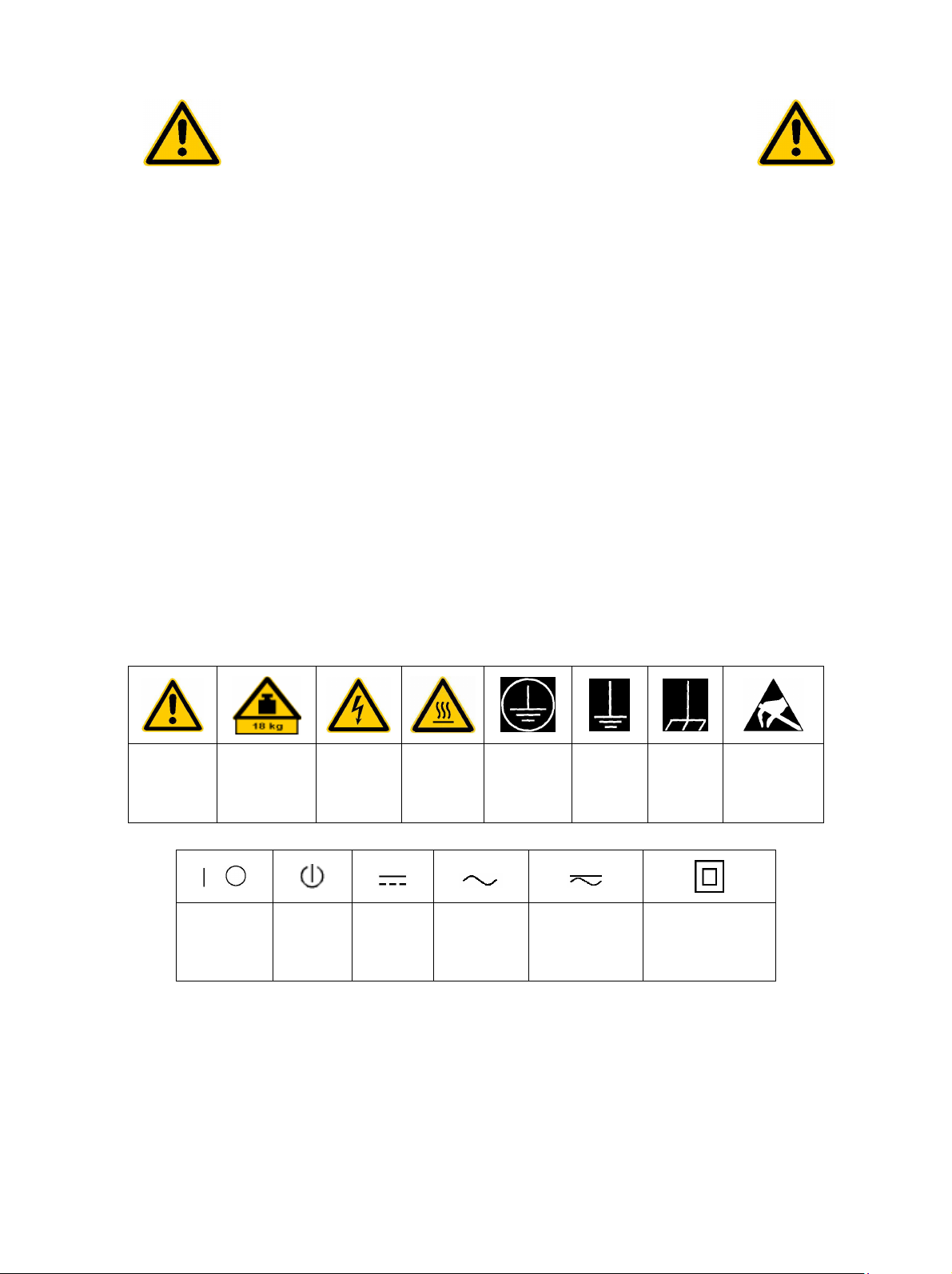
Observe
operating
instructions
Supply
voltage
ON/OFF
Weight
indication for
units >18 kg
Standby
indication
Symbols and safety labels
Danger of
electric
shock
Direct
current
(DC)
Warning!
Hot
surface
PE terminal Ground
Alternating
current (AC)
Direct/alternating
current (DC/AC)
Ground
terminal
Device fully
protected by
double/reinforced
insulation
Attention!
Electrostatic
sensitive
devices
1171.0000.42-02.00 Sheet 1
Page 6

Safety Instructions
Observing the safety instructions will help prevent personal injury or damage of any kind caused by
dangerous situations. Therefore, carefully read through and adhere to the following safety instructions
before putting the product into operation. It is also absolutely essential to observe the additional safety
instructions on personal safety that appear in other parts of the documentation. In these safety
instructions, the word "product" refers to all merchandise sold and distributed by Rohde & Schwarz,
including instruments, systems and all accessories.
Tags and their meaning
DANGER
WARNING
CAUTION This tag indicates a safety hazard with a low potential of risk for the user
ATTENTION
NOTE
These tags are in accordance with the standard definition for civil applications in the European
Economic Area. Definitions that deviate from the standard definition may also exist. It is therefore
essential to make sure that the tags described here are always used only in connection with the
associated documentation and the associated product. The use of tags in connection with unassociated
products or unassociated documentation can result in misinterpretations and thus contribute to personal
injury or material damage.
This tag indicates a safety hazard with a high potential of risk for the
user that can result in death or serious injuries.
This tag indicates a safety hazard with a medium potential of risk for the
user that can result in death or serious injuries.
that can result in slight or minor injuries.
This tag indicates the possibility of incorrect use that can cause damage
to the product.
This tag indicates a situation where the user should pay special attention
to operating the product but which does not lead to damage.
Basic safety instructions
1. The product may be operated only under
the operating conditions and in the
positions specified by the manufacturer. Its
ventilation must not be obstructed during
operation. Unless otherwise specified, the
following requirements apply to
Rohde & Schwarz products:
prescribed operating position is always with
the housing floor facing down, IP protection
2X, pollution severity 2, overvoltage
category 2, use only in enclosed spaces,
max. operation altitude max. 2000 m.
Unless specified otherwise in the data
sheet, a tolerance of ±10% shall apply to
the nominal voltage and of ±5% to the
nominal frequency.
2. Applicable local or national safety
regulations and rules for the prevention of
accidents must be observed in all work
performed. The product may be opened
only by authorized, specially trained
personnel. Prior to performing any work on
the product or opening the product, the
product must be disconnected from the
supply network. Any adjustments,
replacements of parts, maintenance or
repair must be carried out only by technical
personnel authorized by Rohde & Schwarz.
Only original parts may be used for
replacing parts relevant to safety (e.g.
power switches, power transformers,
fuses). A safety test must always be
performed after parts relevant to safety
have been replaced (visual inspection, PE
conductor test, insulation resistance
measurement, leakage current
measurement, functional test).
3. As with all industrially manufactured goods,
the use of substances that induce an
allergic reaction (allergens, e.g. nickel)
such as aluminum cannot be generally
excluded. If you develop an allergic
reaction (such as a skin rash, frequent
sneezing, red eyes or respiratory
difficulties), consult a physician immediately
to determine the cause.
1171.0000.42-02.00 Sheet 2
Page 7

Safety Instructions
4. If products/components are mechanically
and/or thermically processed in a manner
that goes beyond their intended use,
hazardous substances (heavy-metal dust
such as lead, beryllium, nickel) may be
released. For this reason, the product may
only be disassembled, e.g. for disposal
purposes, by specially trained personnel.
Improper disassembly may be hazardous to
your health. National waste disposal
regulations must be observed.
5. If handling the product yields hazardous
substances or fuels that must be disposed
of in a special way, e.g. coolants or engine
oils that must be replenished regularly, the
safety instructions of the manufacturer of
the hazardous substances or fuels and the
applicable regional waste disposal
regulations must be observed. Also
observe the relevant safety instructions in
the product documentation.
6. Depending on the function, certain products
such as RF radio equipment can produce
an elevated level of electromagnetic
radiation. Considering that unborn life
requires increased protection, pregnant
women should be protected by appropriate
measures. Persons with pacemakers may
also be endangered by electromagnetic
radiation. The employer is required to
assess workplaces where there is a special
risk of exposure to radiation and, if
necessary, take measures to avert the
danger.
7. Operating the products requires special
training and intense concentration. Make
certain that persons who use the products
are physically, mentally and emotionally fit
enough to handle operating the products;
otherwise injuries or material damage may
occur. It is the responsibility of the
employer to select suitable personnel for
operating the products.
8. Prior to switching on the product, it must be
ensured that the nominal voltage setting on
the product matches the nominal voltage of
the AC supply network. If a different voltage
is to be set, the power fuse of the product
may have to be changed accordingly.
9. In the case of products of safety class I with
movable power cord and connector,
operation is permitted only on sockets with
earthing contact and protective earth
connection.
10. Intentionally breaking the protective earth
connection either in the feed line or in the
product itself is not permitted. Doing so can
result in the danger of an electric shock
from the product. If extension cords or
connector strips are implemented, they
must be checked on a regular basis to
ensure that they are safe to use.
11. If the product has no power switch for
disconnection from the AC supply, the plug
of the connecting cable is regarded as the
disconnecting device. In such cases, it
must be ensured that the power plug is
easily reachable and accessible at all times
(length of connecting cable approx. 2 m).
Functional or electronic switches are not
suitable for providing disconnection from
the AC supply. If products without power
switches are integrated in racks or systems,
a disconnecting device must be provided at
the system level.
12. Never use the product if the power cable is
damaged. By taking appropriate safety
measures and carefully laying the power
cable, ensure that the cable cannot be
damaged and that no one can be hurt by
e.g. tripping over the cable or suffering an
electric shock.
13. The product may be operated only from
TN/TT supply networks fused with max.
16 A.
14. Do not insert the plug into sockets that are
dusty or dirty. Insert the plug firmly and all
the way into the socket. Otherwise this can
result in sparks, fire and/or injuries.
15. Do not overload any sockets, extension
cords or connector strips; doing so can
cause fire or electric shocks.
16. For measurements in circuits with voltages
V
> 30 V, suitable measures (e.g.
rms
appropriate measuring equipment, fusing,
current limiting, electrical separation,
insulation) should be taken to avoid any
hazards.
17. Ensure that the connections with
information technology equipment comply
with IEC 950/EN 60950.
18. Never remove the cover or part of the
housing while you are operating the
product. This will expose circuits and
components and can lead to injuries, fire or
damage to the product.
1171.0000.42-02.00 Sheet 3
Page 8

Safety Instructions
19. If a product is to be permanently installed,
the connection between the PE terminal on
site and the product's PE conductor must
be made first before any other connection
is made. The product may be installed and
connected only by a skilled electrician.
20. For permanently installed equipment
without built-in fuses, circuit breakers or
similar protective devices, the supply circuit
must be fused in such a way that suitable
protection is provided for users and
products.
21. Do not insert any objects into the openings
in the housing that are not designed for this
purpose. Never pour any liquids onto or into
the housing. This can cause short circuits
inside the product and/or electric shocks,
fire or injuries.
22. Use suitable overvoltage protection to
ensure that no overvoltage (such as that
caused by a thunderstorm) can reach the
product. Otherwise the operating personnel
will be endangered by electric shocks.
23. Rohde & Schwarz products are not
protected against penetration of water,
unless otherwise specified (see also safety
instruction 1.). If this is not taken into
account, there exists the danger of electric
shock or damage to the product, which can
also lead to personal injury.
24. Never use the product under conditions in
which condensation has formed or can form
in or on the product, e.g. if the product was
moved from a cold to a warm environment.
matching Rohde & Schwarz type (see
spare parts list). Batteries and storage
batteries are hazardous waste. Dispose of
them only in specially marked containers.
Observe local regulations regarding waste
disposal. Do not short-circuit batteries or
storage batteries.
28. Please be aware that in the event of a fire,
toxic substances (gases, liquids etc.) that
may be hazardous to your health may
escape from the product.
29. Please be aware of the weight of the
product. Be careful when moving it;
otherwise you may injure your back or other
parts of your body.
30. Do not place the product on surfaces,
vehicles, cabinets or tables that for reasons
of weight or stability are unsuitable for this
purpose. Always follow the manufacturer's
installation instructions when installing the
product and fastening it to objects or
structures (e.g. walls and shelves).
31. Handles on the products are designed
exclusively for personnel to hold or carry
the product. It is therefore not permissible
to use handles for fastening the product to
or on means of transport such as cranes,
fork lifts, wagons, etc. The user is
responsible for securely fastening the
products to or on the means of transport
and for observing the safety regulations of
the manufacturer of the means of transport.
Noncompliance can result in personal injury
or material damage.
25. Do not close any slots or openings on the
product, since they are necessary for
ventilation and prevent the product from
overheating. Do not place the product on
soft surfaces such as sofas or rugs or
inside a closed housing, unless this is well
ventilated.
26. Do not place the product on heatgenerating devices such as radiators or fan
heaters. The temperature of the
environment must not exceed the maximum
temperature specified in the data sheet.
27. Batteries and storage batteries must not be
exposed to high temperatures or fire. Keep
batteries and storage batteries away from
children. If batteries or storage batteries are
improperly replaced, this can cause an
explosion (warning: lithium cells). Replace
the battery or storage battery only with the
1171.0000.42-02.00 Sheet 4
32. If you use the product in a vehicle, it is the
sole responsibility of the driver to drive the
vehicle safely. Adequately secure the
product in the vehicle to prevent injuries or
other damage in the event of an accident.
Never use the product in a moving vehicle if
doing so could distract the driver of the
vehicle. The driver is always responsible for
the safety of the vehicle; the manufacturer
assumes no responsibility for accidents or
collisions.
33. If a laser product (e.g. a CD/DVD drive) is
integrated in a Rohde & Schwarz product,
do not use any other settings or functions
than those described in the documentation.
Otherwise this may be hazardous to your
health, since the laser beam can cause
irreversible damage to your eyes. Never try
to take such products apart, and never look
into the laser beam.
Page 9
Por favor lea imprescindiblemente antes de
la primera puesta en funcionamiento las
siguientes informaciones de seguridad
Informaciones de seguridad
Es el principio de Rohde & Schwarz de tener a sus productos siempre al día con los estandards de
seguridad y de ofrecer a sus clientes el máximo grado de seguridad. Nuestros productos y todos los
equipos adicionales son siempre fabricados y examinados según las normas de seguridad vigentes.
Nuestra sección de gestión de la seguridad de calidad controla constantemente que sean cumplidas
estas normas. Este producto ha sido fabricado y examinado según el comprobante de conformidad
adjunto según las normas de la CE y ha salido de nuestra planta en estado impecable según los
estandards técnicos de seguridad. Para poder preservar este estado y garantizar un funcionamiento
libre de peligros, deberá el usuario atenerse a todas las informaciones, informaciones de seguridad y
notas de alerta. Rohde&Schwarz está siempre a su disposición en caso de que tengan preguntas
referentes a estas informaciones de seguridad.
Además queda en la responsabilidad del usuario utilizar el producto en la forma debida. Este producto
solamente fue elaborado para ser utilizado en la indústria y el laboratorio o para fines de campo y de
ninguna manera deberá ser utilizado de modo que alguna persona/cosa pueda ser dañada. El uso del
producto fuera de sus fines definidos o despreciando las informaciones de seguridad del fabricante
queda en la responsabilidad del usuario. El fabricante no se hace en ninguna forma responsable de
consecuencias a causa del maluso del producto.
Se parte del uso correcto del producto para los fines definidos si el producto es utilizado dentro de las
instrucciones del correspondiente manual del uso y dentro del margen de rendimiento definido (ver
hoja de datos, documentación, informaciones de seguridad que siguen). El uso de los productos hace
necesarios conocimientos profundos y el conocimiento del idioma inglés. Por eso se deberá tener en
cuenta de exclusivamente autorizar para el uso de los productos a personas péritas o debidamente
minuciosamente instruidas con los conocimientos citados. Si fuera necesaria indumentaria de
seguridad para el uso de productos de R&S, encontrará la información debida en la documentación del
producto en el capítulo correspondiente.
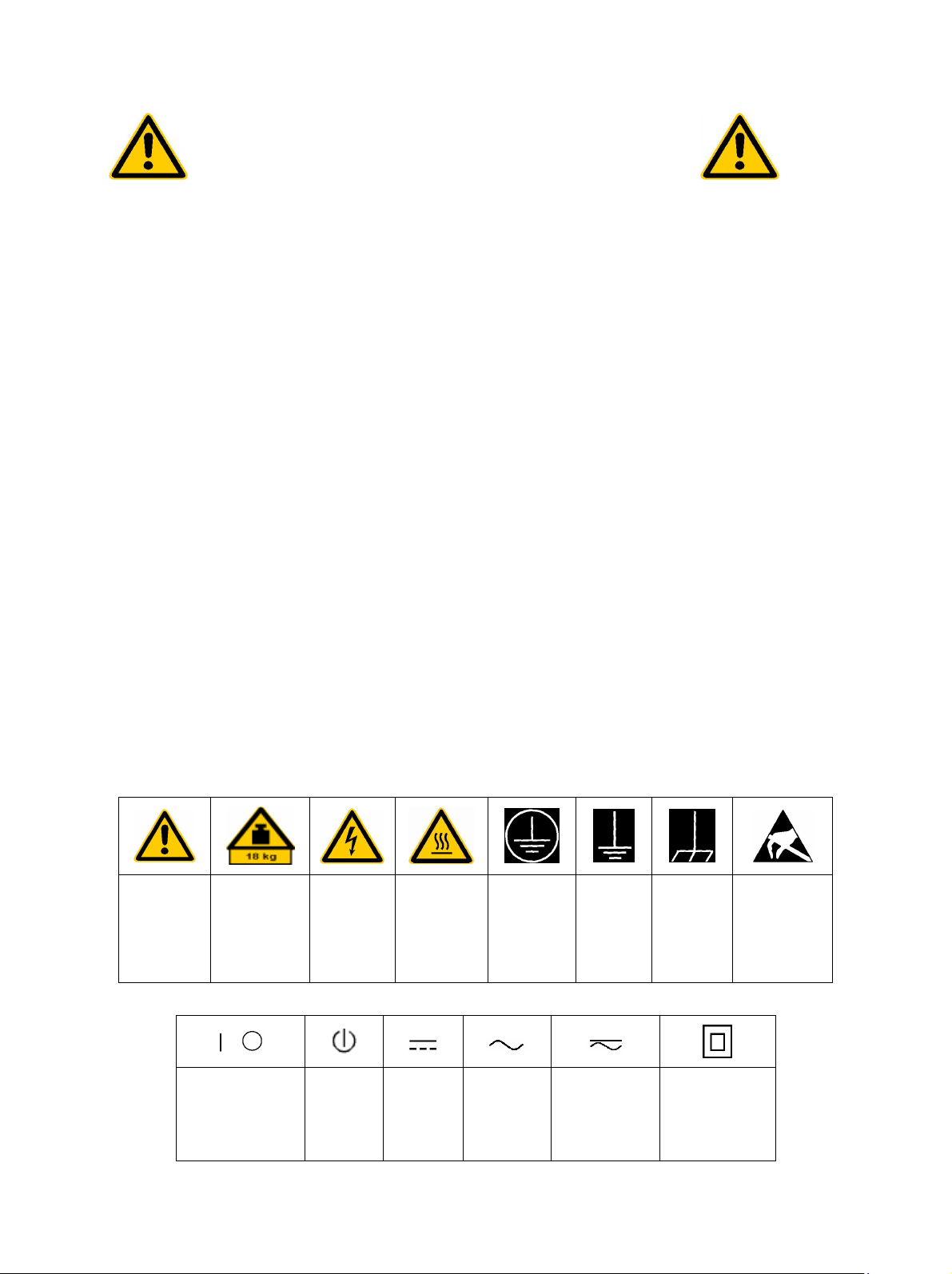
Símbolos y definiciones de seguridad
Ver manual
de
instrucciones
del uso
Informaciones
para
maquinaria
con uns peso
de > 18kg
Peligro de
golpe de
corriente
¡Advertencia!
Superficie
caliente
Conexión a
conductor
protector
Conexión
a tierra
Conexión
a masa
conductora
¡Cuidado!
Elementos de
construción
con peligro de
carga
electroestática
El aparato está
protegido en su
totalidad por un
aislamiento de
doble refuerzo
potencia EN
MARCHA/PARADA
Indicación
Stand-by
Corriente
continua
DC
Corriente
alterna AC
Corriente
continua/alterna
DC/AC
1171.0000.42-02.00 página 1
Page 10

Informaciones de seguridad
Tener en cuenta las informaciones de seguridad sirve para tratar de evitar daños y peligros de toda
clase. Es necesario de que se lean las siguientes informaciones de seguridad concienzudamente y se
tengan en cuenta debidamente antes de la puesta en funcionamiento del producto. También deberán
ser tenidas en cuenta las informaciones para la protección de personas que encontrarán en otro
capítulo de esta documentación y que también son obligatorias de seguir. En las informaciones de
seguridad actuales hemos juntado todos los objetos vendidos por Rohde&Schwarz bajo la
denominación de „producto“, entre ellos también aparatos, instalaciones así como toda clase de
accesorios.
Palabras de señal y su significado
PELIGRO Indica un punto de peligro con gran potencial de riesgo para el
ususario.Punto de peligro que puede llevar hasta la muerte o graves
heridas.
ADVERTENCIA Indica un punto de peligro con un protencial de riesgo mediano para el
usuario. Punto de peligro que puede llevar hasta la muerte o graves
heridas .
ATENCIÓN Indica un punto de peligro con un protencial de riesgo pequeño para el
usuario. Punto de peligro que puede llevar hasta heridas leves o
pequeñas
CUIDADO Indica la posibilidad de utilizar mal el producto y a consecuencia
dañarlo.
INFORMACIÓN Indica una situación en la que deberían seguirse las instrucciones en el
uso del producto, pero que no consecuentemente deben de llevar a un
daño del mismo.
Las palabras de señal corresponden a la definición habitual para aplicaciones civiles en el ámbito de la
comunidad económica europea. Pueden existir definiciones diferentes a esta definición. Por eso se
debera tener en cuenta que las palabras de señal aquí descritas sean utilizadas siempre solamente en
combinación con la correspondiente documentación y solamente en combinación con el producto
correspondiente. La utilización de las palabras de señal en combinación con productos o
documentaciones que no les correspondan puede llevar a malinterpretaciones y tener por
consecuencia daños en personas u objetos.
Informaciones de seguridad elementales
1. El producto solamente debe ser utilizado
según lo indicado por el fabricante referente
a la situación y posición de funcionamiento
sin que se obstruya la ventilación. Si no se
convino de otra manera, es para los
productos R&S válido lo que sigue:
como posición de funcionamiento se define
principialmente la posición con el suelo de la
caja para abajo , modo de protección IP 2X,
grado de suciedad 2, categoría de
sobrecarga eléctrica 2, utilizar solamente en
estancias interiores, utilización hasta 2000 m
sobre el nivel del mar.
A menos que se especifique otra cosa en la
hoja de datos, se aplicará una tolerancia de
±10% sobre el voltaje nominal y de ±5%
sobre la frecuencia nominal.
2. En todos los trabajos deberán ser tenidas en
cuenta las normas locales de seguridad de
trabajo y de prevención de accidentes. El
producto solamente debe de ser abierto por
personal périto autorizado. Antes de efectuar
trabajos en el producto o abrirlo deberá este
ser desconectado de la corriente. El ajuste,
el cambio de partes, la manutención y la
reparación deberán ser solamente
efectuadas por electricistas autorizados por
R&S. Si se reponen partes con importancia
para los aspectos de seguridad (por ejemplo
el enchufe, los transformadores o los
fusibles), solamente podrán ser sustituidos
por partes originales. Despues de cada
recambio de partes elementales para la
seguridad deberá ser efectuado un control de
1171.0000.42-02.00 página 2
Page 11

Informaciones de seguridad
seguridad (control a primera vista, control de
conductor protector, medición de resistencia
de aislamiento, medición de medición de la
corriente conductora, control de
funcionamiento).
3. Como en todo producto de fabricación
industrial no puede ser excluido en general
de que se produzcan al usarlo elementos
que puedan generar alergias, los llamados
elementos alergénicos (por ejemplo el
níquel). Si se producieran en el trato con
productos R&S reacciones alérgicas, como
por ejemplo urticaria, estornudos frecuentes,
irritación de la conjuntiva o dificultades al
respirar, se deberá consultar inmediatamente
a un médico para averigurar los motivos de
estas reacciones.
4. Si productos / elementos de construcción son
tratados fuera del funcionamiento definido de
forma mecánica o térmica, pueden generarse
elementos peligrosos (polvos de sustancia
de metales pesados como por ejemplo
plomo, berilio, níquel). La partición elemental
del producto, como por ejemplo sucede en el
tratamiento de materias residuales, debe de
ser efectuada solamente por personal
especializado para estos tratamientos. La
partición elemental efectuada
inadecuadamente puede generar daños para
la salud. Se deben tener en cuenta las
directivas nacionales referentes al
tratamiento de materias residuales.
5. En el caso de que se produjeran agentes de
peligro o combustibles en la aplicación del
producto que debieran de ser transferidos a
un tratamiento de materias residuales, como
por ejemplo agentes refrigerantes que deben
ser repuestos en periodos definidos, o
aceites para motores, deberan ser tenidas en
cuenta las prescripciones de seguridad del
fabricante de estos agentes de peligro o
combustibles y las regulaciones regionales
para el tratamiento de materias residuales.
Cuiden también de tener en cuenta en caso
dado las prescripciones de seguridad
especiales en la descripción del producto.
6. Ciertos productos, como por ejemplo las
instalaciones de radiación HF, pueden a
causa de su función natural, emitir una
radiación electromagnética aumentada. En
vista a la protección de la vida en desarrollo
deberían ser protegidas personas
embarazadas debidamente. También las
personas con un bypass pueden correr
peligro a causa de la radiación
electromagnética. El empresario está
comprometido a valorar y señalar areas de
trabajo en las que se corra un riesgo de
exposición a radiaciones aumentadas de
riesgo aumentado para evitar riesgos.
7. La utilización de los productos requiere
instrucciones especiales y una alta
concentración en el manejo. Debe de
ponerse por seguro de que las personas que
manejen los productos estén a la altura de
los requerimientos necesarios referente a
sus aptitudes físicas, psíquicas y
emocionales, ya que de otra manera no se
pueden excluir lesiones o daños de objetos.
El empresario lleva la responsabilidad de
seleccionar el personal usuario apto para el
manejo de los productos.
8. Antes de la puesta en marcha del producto
se deberá tener por seguro de que la tensión
preseleccionada en el producto equivalga a
la del la red de distribución. Si es necesario
cambiar la preselección de la tensión
también se deberán en caso dabo cambiar
los fusibles correspondientes del prodcuto.
9. Productos de la clase de seguridad I con
alimentación móvil y enchufe individual de
producto solamente deberán ser conectados
para el funcionamiento a tomas de corriente
de contacto de seguridad y con conductor
protector conectado.
10. Queda prohibida toda clase de interrupción
intencionada del conductor protector, tanto
en la toma de corriente como en el mismo
producto ya que puede tener como
consecuencia el peligro de golpe de corriente
por el producto. Si se utilizaran cables o
enchufes de extensión se deberá poner al
seguro, que es controlado su estado técnico
de seguridad.
11. Si el producto no está equipado con un
interruptor para desconectarlo de la red, se
deberá considerar el enchufe del cable de
distribución como interruptor. En estos casos
deberá asegurar de que el enchufe sea de
fácil acceso y nabejo (medida del cable de
distribución aproximadamente 2 m). Los
interruptores de función o electrónicos no
son aptos para el corte de la red eléctrica. Si
los productos sin interruptor están integrados
en construciones o instalaciones, se deberá
instalar el interruptor al nivel de la
instalación.
1171.0000.42-02.00 página 3
Page 12

Informaciones de seguridad
12. No utilice nunca el producto si está dañado el
cable eléctrico. Asegure a través de las
medidas de protección y de instalación
adecuadas de que el cable de eléctrico no
pueda ser dañado o de que nadie pueda ser
dañado por él, por ejemplo al tropezar o por
un golpe de corriente.
13. Solamente está permitido el funcionamiento
en redes de distribución TN/TT aseguradas
con fusibles de como máximo 16 A.
14. Nunca conecte el enchufe en tomas de
corriente sucias o llenas de polvo. Introduzca
el enchufe por completo y fuertemente en la
toma de corriente. Si no tiene en
consideración estas indicaciones se arriesga
a que se originen chispas, fuego y/o heridas.
15. No sobrecargue las tomas de corriente, los
cables de extensión o los enchufes de
extensión ya que esto pudiera causar fuego
o golpes de corriente.
16. En las mediciones en circuitos de corriente
con una tensión de entrada de Ueff > 30 V se
deberá tomar las precauciones debidas para
impedir cualquier peligro (por ejemplo
medios de medición adecuados, seguros,
limitación de tensión, corte protector,
aislamiento etc.).
17. En caso de conexión con aparatos de la
técnica informática se deberá tener en
cuenta que estos cumplan los requisitos de
la EC950/EN60950.
18. Nunca abra la tapa o parte de ella si el
producto está en funcionamiento. Esto pone
a descubierto los cables y componentes
eléctricos y puede causar heridas, fuego o
daños en el producto.
19. Si un producto es instalado fijamente en un
lugar, se deberá primero conectar el
conductor protector fijo con el conductor
protector del aparato antes de hacer
cualquier otra conexión. La instalación y la
conexión deberán ser efecutadas por un
electricista especializado.
20. En caso de que los productos que son
instalados fijamente en un lugar sean sin
protector implementado, autointerruptor o
similares objetos de protección, deberá la
toma de corriente estar protegida de manera
que los productos o los usuarios estén
suficientemente protegidos.
21. Por favor, no introduzca ningún objeto que
no esté destinado a ello en los orificios de la
caja del aparato. No vierta nunca ninguna
clase de líquidos sobre o en la caja. Esto
puede producir corto circuitos en el producto
y/o puede causar golpes de corriente, fuego
o heridas.
22. Asegúrese con la protección adecuada de
que no pueda originarse en el producto una
sobrecarga por ejemplo a causa de una
tormenta. Si no se verá el personal que lo
utilice expuesto al peligro de un golpe de
corriente.
23. Los productos R&S no están protegidos
contra el agua si no es que exista otra
indicación, ver también punto 1. Si no se
tiene en cuenta esto se arriesga el peligro de
golpe de corriente o de daños en el producto
lo cual también puede llevar al peligro de
personas.
24. No utilice el producto bajo condiciones en las
que pueda producirse y se hayan producido
líquidos de condensación en o dentro del
producto como por ejemplo cuando se
desplaza el producto de un lugar frío a un
lugar caliente.
25. Por favor no cierre ninguna ranura u orificio
del producto, ya que estas son necesarias
para la ventilación e impiden que el producto
se caliente demasiado. No pongan el
producto encima de materiales blandos como
por ejemplo sofás o alfombras o dentro de
una caja cerrada, si esta no está
suficientemente ventilada.
26. No ponga el producto sobre aparatos que
produzcan calor, como por ejemplo
radiadores o calentadores. La temperatura
ambiental no debe superar la temperatura
máxima especificada en la hoja de datos.
1171.0000.42-02.00 página 4
Page 13

Informaciones de seguridad
27. Baterías y acumuladores no deben de ser
expuestos a temperaturas altas o al fuego.
Guardar baterías y acumuladores fuera del
alcance de los niños. Si las baterías o los
acumuladores no son cambiados con la
debida atención existirá peligro de explosión
(atención celulas de Litio). Cambiar las
baterías o los acumuladores solamente por
los del tipo R&S correspondiente (ver lista de
piezas de recambio). Baterías y
acumuladores son deshechos problemáticos.
Por favor tirenlos en los recipientes
especiales para este fín. Por favor tengan en
cuenta las prescripciones nacionales de cada
país referente al tratamiento de deshechos.
Nunca sometan las baterías o acumuladores
a un corto circuito.
28. Tengan en consideración de que en caso de
un incendio pueden escaparse gases tóxicos
del producto, que pueden causar daños a la
salud.
29. Por favor tengan en cuenta que en caso de
un incendio pueden desprenderse del
producto agentes venenosos (gases, líquidos
etc.) que pueden generar daños a la salud.
30. No sitúe el producto encima de superficies,
vehículos, estantes o mesas, que por sus
características de peso o de estabilidad no
sean aptas para él. Siga siempre las
instrucciones de instalación del fabricante
cuando instale y asegure el producto en
objetos o estructuras (por ejemplo paredes y
estantes).
31. Las asas instaladas en los productos sirven
solamente de ayuda para el manejo que
solamente está previsto para personas. Por
eso no está permitido utilizar las asas para la
sujecion en o sobre medios de transporte
como por ejemplo grúas, carretillas
elevadoras de horquilla, carros etc. El
usuario es responsable de que los productos
sean sujetados de forma segura a los medios
de transporte y de que las prescripciones de
seguridad del fabricante de los medios de
transporte sean tenidas en cuenta. En caso
de que no se tengan en cuenta pueden
causarse daños en personas y objetos.
32. Si llega a utilizar el producto dentro de un
vehículo, queda en la responsabilidad
absoluta del conductor que conducir el
vehículo de manera segura. Asegure el
producto dentro del vehículo debidamente
para evitar en caso de un accidente las
lesiones u otra clase de daños. No utilice
nunca el producto dentro de un vehículo en
movimiento si esto pudiera distraer al
conductor. Siempre queda en la
responsabilidad absoluta del conductor la
seguridad del vehículo y el fabricante no
asumirá ninguna clase de responsabilidad
por accidentes o colisiones.
33. Dado el caso de que esté integrado un
producto de laser en un producto R&S (por
ejemplo CD/DVD-ROM) no utilice otras
instalaciones o funciones que las descritas
en la documentación. De otra manera pondrá
en peligro su salud, ya que el rayo laser
puede dañar irreversiblemente sus ojos.
Nunca trate de descomponer estos
productos. Nunca mire dentro del rayo laser.
1171.0000.42-02.00 página 5
Page 14

Page 15

DIN EN ISO 9001 : 2000
DIN EN 9100 : 2003
DIN EN ISO 14001 : 1996
DQS REG. NO 001954 QM/ST UM
Certified Quality System
Sehr geehrter Kunde,
Sie haben sich für den Kauf eines
Rohde & Schwarz-Produktes entschieden. Hiermit erhalten Sie ein nach
modernsten Fertigungsmethoden
hergestelltes Produkt. Es wurde nach
den Regeln unseres Managementsystems entwickelt, gefertigt und
geprüft.
Das Rohde & Schwarz Managementsystem ist zertifiziert nach:
DIN EN ISO 9001:2000
DIN EN 9100:2003
DIN EN ISO 14001:1996
Dear Customer,
you have decided to buy a Rohde &
Schwarz product. You are thus assured of receiving a product that is
manufactured using the most modern
methods available. This product was
developed, manufactured and tested
in compliance with our quality management system standards.
The Rohde & Schwarz quality management system is certified according to:
DIN EN ISO 9001:2000
DIN EN 9100:2003
DIN EN ISO 14001:1996
Cher Client,
vous avez choisi d‘acheter un produit
Rohde & Schwarz. Vous disposez
donc d‘un produit fabriqué d‘après
les méthodes les plus avancées. Le
développement, la fabrication et les
tests respectent nos normes de gestion qualité.
Le système de gestion qualité de
Rohde & Schwarz a été homologué
conformément aux normes:
DIN EN ISO 9001:2000
DIN EN 9100:2003
DIN EN ISO 14001:1996
QUALITÄTSZERTIFIKAT CERTIFICATE OF QUALITY CERTIFICAT DE QUALITÉ
Page 16

Page 17

Certificate No.: 9502002
This is to certify that:
Equipment type Order No. Designation
FSEA20/30 1065.6000.20/.25/.30/.35 Spectrum Analyzer
FSEB20/30 1066.3010.20/.25/.30/.35
FSEK20/21 1088.1491.20/.21/.25
FSEK30/31 1088.3494.30/.31/.35
FSEM20/21 1080.1505.20/.21/.25
FSEM30/31 1079.8500.30/.31/.35
EC Certificate of Conformity
complies with the provisions of the Directive of the Council of the European Union on the
approximation of the laws of the Member Stat es
- relating to electrical equipment for use within defined voltage lim its
(73/23/EEC revised by 93/68/EEC)
- relating to electromag netic compatibility
(89/336/EEC revised by 91/263/EEC, 92/31/EEC, 93/68/ EEC)
Conformity is proven by compliance with the following standards:
EN61010-1 : 1991
EN55011 : 1998 + A1 : 1999, Klasse B
EN61000-3-2 : 1995 + A1 : 1998 + A2 : 1998 + A14 : 2000
EN61000-3-3 : 1995
EN50082-1 : 1992
Affixing the EC confor m it y mark as from 1995
ROHDE & SCHWARZ GmbH & Co. KG
Mühldorfstr. 15, D-81671 München
Munich, 2001-01-11 Central Quality Management FS-QZ / Becker
1065.6000.20 CE E-7
Page 18

Page 19

Certificate No.: 9502052
This is to certify that:
Equipment type Stock No. Designation
FSE-B1 1073.4990.02 Color Display
FSE-B10 1066.4769.02 Tracking Generator
FSE-B11 1066.4917.02 Tracking Generator
FSE-B12 1066.5065.02 Output Attenuator
FSE-B13 1119.6499.02 1 dB Input Attenuator
FSE-B15 1073.5696.02/.03 Computer Function
FSE-B16 1073.5973.02/.03/.04 Ethernet Interface
FSE-B17 1066.4017.02 2nd IEC BUS Interface
FSE-B18 1088.6993.02 Removeable Harddrive
FSE-B19 1088.7248.xx Second Harddisk
FSE-B2 1073.5044.02 7 GHz Frequency Extension
FSE-B21 1084.7243.02 External Mixer Output
FSE-B23 1088.7348.02 741,4 MHz Broadband Output
FSE-B24 1106.3680.02 44 GHz Frequency Extension
FSE-B3 1073.5244.02 TV Demodulator
FSE-B4 1073.5396.02 OCXO 10 MHz and Low Phase Noise
FSE-B7 1066.4317.02 Signal Vectoranalysis
FSE-B77 1102.8493.02 Signal Vectoranalysis
FSE-B8 1066.4469.02 Tracking Generator
FSE-B9 1066.4617.02 Tracking Generator
FSE-Z2 1084.7043.02 PS/2 Mouse
EC Certificate of Conformity
complies with the provisions of the Directive of the Council of the European Union on the approximation
of the laws of the Member States
- relating to electromagnetic compatibility
(89/336/EEC revised by 91/263/EEC, 92/31/EEC, 93/68/EEC)
Conformity is proven by compliance with the following standards:
EN55011 : 1998 + A1 : 1999, Klasse B
EN61000-3-2 : 1995 + A1 : 1998 + A2 : 1998 + A14 : 2000
EN61000-3-3 : 1995
EN50082-1 : 1992
Affixing the EC conformity mark as from 1995
ROHDE & SCHWARZ GmbH & Co. KG
Mühldorfstr. 15, D-81671 München
Munich, 2001-01-11 Central Quality Management FS-QZ / Becker
1073.4990.02 CE E-11
Page 20

Page 21

Customer Support
Technical support – where and when you need it
For quick, expert help with any Rohde & Schwarz equipment, contact one of our
Customer Support Centers. A team of highly qualified engineers provides telephone
support and will work with you to find a solution to your query on any aspect of the
operation, programming or applications of Rohde & Schwarz equipment.
Up-to-date information and upgrades
To keep your Rohde & Schwarz equipment always up-to-date,
please subscribe to our electronic newsletter at
http://www.rohde-schwarz.com/www/response.nsf/newsletterpreselection
or request the desired information and upgrades via email from your Customer Support
Center (addresses see below).
Feedback
We want to know if we are meeting your support needs. If you have any comments
please email us and let us know CustomerSupport.Feedback@rohde-schwarz.com.
USA & Canada
East Asia
Rest of the World
Monday to Friday (except US public holidays)
8:00 AM – 8:00 PM Eastern Standard Time (EST)
Tel. from USA 888-test-rsa (888-837-8772) (opt 2)
From outside USA +1 410 910 7800 (opt 2)
Fax +1 410 910 7801
E-mail Customer.Support@rsa.rohde-schwarz.com
Monday to Friday (except Singaporean public holidays)
8:30 AM – 6:00 PM Singapore Time (SGT)
Tel. +65 6 513 0488
Fax +65 6 846 1090
E-mail Customersupport.asia@rohde-schwarz.com
Monday to Friday (except German public holidays)
08:00 – 17:00 Central European Time (CET)
Tel. from Europe +49 (0) 180 512 42 42
From outside Europe +49 89 4129 13776
Fax +49 (0) 89 41 29 637 78
E-mail CustomerSupport@rohde-schwarz.com
1007.8684.14-04.00
Page 22

Page 23

Adressen/Addresses
Algeria
Argentina
Australia
FIRMENSITZ/HEADQUARTERS (Tel) Phone
Rohde & Schwarz GmbH & Co. KG
Mühldorfstraße 15 · D-81671 München
Postfach 80 14 69 · D-81614 München
WERKE/PLANTS
Rohde & Schwarz Messgerätebau GmbH
Riedbachstraße 58 · D-87700 Memmingen
Postfach 1652 · D-87686 Memmingen
Rohde & Schwarz GmbH & Co. KG
Werk Teisnach
Kaikenrieder Straße 27 · D-94244 Teisnach
Postfach 1149 · D-94240 Teisnach
Rohde & Schwarz GmbH & Co. KG
Dienstleistungszentrum Köln
Graf-Zeppelin-Straße 18 · D-51147 Köln
Postfach 98 02 60 · D-51130 Köln
TOCHTERUNTERNEHMEN/SUBSIDIARIES
Rohde & Schwarz Vertriebs-GmbH
Mühldorfstraße 15 · D-81671 München
Postfach 80 14 69 · D-81614 München
Rohde & Schwarz International GmbH
Mühldorfstraße 15 · D-81671 München
Postfach 80 14 60 · D-81614 München
Rohde & Schwarz Engineering and Sales
GmbH
Mühldorfstraße 15 · D-81671 München
Postfach 80 14 29 · D-81614 München
R&S BICK Mobilfunk GmbH
Fritz-Hahne-Str. 7 · D-31848 Bad Münder
Postfach 2062 · D-31844 Bad Münder
Rohde & Schwarz FTK GmbH
Wendenschlossstraße 168, Haus 28
D-12557 Berlin
Rohde & Schwarz SIT GmbH
Agastraße 3
D-12489 Berlin
R&S Systems GmbH
Graf-Zeppelin-Straße 18 D-51147 Köln
Postfach 98 02 60 D-51130 Köln
ADRESSEN WELTWEIT/ADDRESSES WORLDWIDE
siehe/see AustriaAlbania
Rohde & Schwarz
Bureau d'Alger
5B Place de Laperrine
16035 Hydra-Alger
siehe / see MexicoAntilles (Neth.)
Precision Electronica S.R.L.
Av. Pde Julio A. Roca 710 - 6° Piso
1067 Buenos Aires
Rohde & Schwarz (Australia) Pty. Ltd.
Sales Support
Unit 6
2-8 South Street
Rydalmere, N.S.W. 2116
schwarz.com·service.rsdc@rohde-
alberto.lombardi@prec-elec.com.ar
(Tel) +49 (89) 41 29-0
(Fax) +49 89 4129-121 64
info@rohde-schwarz.com
(Tel) +49 (8331) 108-0
(Fax) +49 (8331) 108-11 24
info.rsdmb@rohde-schwarz.com
(Tel) +49 (9923) 857-0
(Fax) +49 (9923) 857-11 74
info.rsdts@rohde-schwarz.com
(Tel) +49 (2203) 49-0
(Fax) +49 (2203) 49 51-229
(Tel) +49 (89) 41 29-137 74
(Fax) +49 (89) 41 29-137 77
customersupport@rohde-
(Tel) +49 (89) 41 29-129 84
(Fax) +49 (89) 41 29-120 50
info.rusis@rohde-schwarz.com
(Tel) +49 (89) 41 29-137 11
(Fax) +49 (89) 41 29-137 23
info.rse@rohde-schwarz.com
(Tel) +49 (5042) 998-0
(Fax) +49 (5042) 998-105
info.rsbick@rohde-schwarz.com
(Tel) +49 (30) 658 91-122
(Fax) +49 (30) 655 50-221
info.ftk@rohde-schwarz.com
(Tel) +49 (30) 658 84-0
(Fax) +49 (30) 658 84-183
info.sit@rohde-schwarz.com
(Tel) +49 (2203) 49-5 23 25
(Fax) +49 (2203) 49-5 23 36
info.rssys@rohde-schwarz.com
(Tel) +213 (21) 48 20 18
(Fax) +213 (21) 69 46 08
(Tel) +541 (14) 331 10 67
(Fax) +541 (14) 334 51 11
(Tel) +61 (2) 88 45 41 00
(Fax) +61 (2) 96 38 39 88
sales@rsaus.rohde-schwarz.com
(Fax) Fax
E-mail
info.rsdc@rohde-
schwarz.com
schwarz.com
Austria
Azerbaijan
Bangladesh
Belgium
Herzegovina
Brazil
Brunei
Bulgaria
Canada
Chile
China
Rohde & Schwarz-Österreich Ges.m.b.H.
Am Europlatz 3
Gebäude B
1120 Wien
Rohde & Schwarz Azerbaijan
Liaison Office Baku
ISR Plaza, 5th floor
340 Nizami Str.
370000 Baku
BIL Consortium Ltd.
Corporate Office
House-33, Road-4, Block-F
Banani, Dhaka-1213
siehe / see MexicoBarbados
siehe/see UkraineBelarus
Rohde & Schwarz Belgium N.V.
Excelsiorlaan 31 Bus 1
1930 Zaventem
siehe / see MexicoBelize
siehe/see MexicoBermuda
siehe/see SloveniaBosnia-
Rohde & Schwarz Do Brasil Ltda.
Av. Alfredo Egidio de Souza Aranha n° 177,
1° andar - Santo Amaro
04726-170 Sao Paulo - SP
George Keen Lee Equipment Pte Ltd.
#11-01 BP Tower
396 Alexandra Road
Singapore 119954
Rohde & Schwarz
Representation Office Bulgaria
39, Fridtjof Nansen Blvd.
1000 Sofia
Rohde & Schwarz Canada Inc.
555 March Rd.
Kanata, Ontario K2K 2M5
Dymeq Ltda.
Av. Larrain 6666
Santiago
Rohde & Schwarz China Ltd.
Representative Office Beijing
6F, Parkview Center
2 Jiangtai Road
Chao Yang District
Beijing 100016
Rohde & Schwarz China Ltd.
Representative Office Shanghai
Room 807-809, Central Plaza
227 Huangpi North Road
Shanghai 200003
Rohde & Schwarz China Ltd.
Representative Office Guangzhou
Room 2903, Metro Plaza
183 Tian He North Road
Guangzhou 510075
rs-austria@rsoe.rohde-schwarz.com
(general)·+55 (11) 56 44 86 25 (sales)
May.Zhu@rsbp.rohde-schwarz.com
(Tel) +43 (1) 602 61 41-0
(Fax) +43 (1) 602 61 41-14
(Tel) +994 (12) 93 31 38
(Fax) +994 (12) 93 03 14
rs-azerbaijan@rsd.rohde-
info@rsb.rohde-schwarz.com
(Tel) +55 (11) 56 44 86 11
(Fax) +55 (11) 56 44 86 36
rs-bulgaria@rsbg.rohde-schwarz
(Tel) +86 (10) 64 31 28 28
(Fax) +86 (10) 64 37 98 88
info.rschina@rsbp.rohde-
(Tel) +86 (21) 63 75 00 18
(Fax) +86 (21) 63 75 91 70
(Tel) +86 (20) 87 55 47 58
(Fax) +86 (20) 87 55 47 59
schwarz.com
(Tel) +880 (2) 881 06 53
(Fax) +880 (2) 882 82 91
(Tel) +32 (2) 721 50 02
(Fax) +32 (2) 725 09 36
sales-brazil@rsdb.rohde-
schwarz.com
(Tel) +656 276 06 26
(Fax) +656 276 06 29
gkleqpt@singnet.com.sg
(Tel) +359 (2) 96 343 34
(Fax) +359 (2) 963 21 97
(Tel) +1 (613) 592 80 00
(Fax) +1 (613) 592 80 09
sales@rscanada.ca
(Tel) +56 (2) 339 20 00
(Fax) +56 (2) 339 20 10
dymeq@dymeq.com
schwarz.com
Winnie.Lin@rsbp.rohde-
schwarz.com
Page 24

Adressen/Addresses
China
Cyprus
Czech Republic
Denmark
Egypt
Estonia
Finland
France
Germany
Rohde & Schwarz China Ltd.
Representative Office Chengdu
Unit G, 28/F, First City Plaza
308 Shuncheng Avenue
Chengdu 610017
Rohde & Schwarz China Ltd.
Representative Office Xian
Room 603, Jin Xin International
No. 99 Heping Road
Xian 710001
Rohde & Schwarz China Ltd.
Representative Office Shenzhen
Room 1901, Central Business Building
No. 88 Fuhua Yilu
Futian District
Shenzhen 518026
siehe / see MexicoCosta Rica
siehe/see SloveniaCroatia
siehe / see MexicoCuba
Hinis Telecast Ltd.
Agiou Thoma 18
Kiti
Larnaca 7550
Rohde & Schwarz Praha, s.r.o.
Hadovka Office Park
Evropská 2590/33c
16000 Praha 6
Rohde & Schwarz Danmark A/S
Ejby Industrivej 40
2600 Glostrup
U.A.S. Universal Advanced Systems
31 Manshiet El-Bakry Street
Heliopolis
11341 Cairo
siehe/see MexicoEl Salvador
Rohde & Schwarz Danmark A/S
Estonian Branch Office
Narva mnt. 13
10151 Tallinn
Rohde & Schwarz Finland Oy
Taivaltie 5
01610 Vantaa
Rohde & Schwarz France
Immeuble "Le Newton"
9-11, rue Jeanne Braconnier
92366 Meudon La Forêt Cédex
Niederlassung/Subsidiary Rennes
37 Rue du Bignon
Bâtiment A
35510 Cesson Sévigné
Zweigniederlassungen der Rohde &
Schwarz Vertriebs-GmbH/Branch offices of
Rohde & Schwarz Vertriebs-GmbH
Zweigniederlassung Nord, Geschäftsstelle
Berlin
Ernst-Reuter-Platz 10 · D-10587 Berlin
Postfach 100620 · D-10566 Berlin
sherry.yu@rsbp.rohde-schwarz.com
jessica.lia@rsbp.rohde-schwarz.com
estonia@rsdk.rohde-schwarz.com
(Tel) +86 (28) 86 52 76 06
(Fax) +86 (28) 86 52 76 10
sophia.chen@rsbp.rohde-
(Tel) +86 (29) 87 41 53 77
(Fax) +86 (29) 87 20 65 00
(Tel) +86 (755) 82 03 11 98
(Fax) +86 (755) 82 03 30 70
(Tel) +420 (2) 24 31 12 32
(Fax) +420 (2) 24 31 70 43
office@rscz.rohde-schwarz.com
rsdk@rsdk.rohde-schwarz.com
(Tel) +358 (207) 60 04 00
(Fax) +358 (207) 60 04 17
info@rsfin.rohde-schwarz.com
(Tel) +33 (0) 141 36 10 00
(Fax) +33 (0) 141 36 11 11
contact@rsf.rohde-schwarz.com
(Fax) +49 (30) 34 79 48 48
info.rsv@rohde-schwarz.com
schwarz.com
(Tel) +357 (24) 42 51 78
(Fax) +357 (24) 42 46 21
hinis@logos.cy.net
(Tel) +45 (43) 43 66 99
(Fax) +45 (43) 43 77 44
(Tel) +20 (2) 455 67 44
(Fax) +20 (2) 256 17 40
an_uas@link.net
(Tel) +372 (6) 14 31 23
(Fax) +372 (6) 14 31 21
(Tel) +33 (2) 99 51 97 00
(Fax) +33 (2) 99 51 98 77
(Tel) +49 (30) 34 79 48-0
Germany
Ghana
Greece
Hong Kong
Hungary
India
Zweigniederlassung Büro Bonn
Josef-Wirmer-Straße 1-3 · D-53123 Bonn
Postfach 140264 · D-53057 Bonn
Zweigniederlassung Nord, Geschäftsstelle
Hamburg
Vierenkamp 6 D-22423 Hamburg
Zweigniederlassung Mitte, Geschäftsstelle
Köln
Niederkasseler Straße 33 · D-51147 Köln
Postfach 900 149 · D-51111 Köln
Zweigniederlassung Süd, Geschäftsstelle
München
Mühldorfstraße 15 · D-81671 München
Postfach 80 14 69 · D-81614 München
Zweigniederlassung Süd, Geschäftsstelle
Nürnberg
Donaustraße 36
D-90451 Nürnberg
Zweigniederlassung Mitte, Geschäftsstelle
Neu-Isenburg
Siemensstraße 20 D-63263 Neu-Isenburg
Postfach 16 51 D-63236 Neu-Isenburg
Kop Engineering Ltd.
P.O. Box 11012
3rd Floor Akai House, Osu
Accra North
Mercury S.A.
6, Loukianou Str.
10675 Athens
siehe/see Mexico Guatemala
siehe / see MexicoGuiana
siehe / see MexicoHaiti
siehe/see Mexico Honduras
Electronic Scientific Engineering
9/F North Somerset House
Taikoo Place
979 King's Road, Quarry Bay
Hong Kong
Rohde & Schwarz
Budapesti Iroda
Váci út 169
1138 Budapest
siehe/see DenmarkIceland
Rohde & Schwarz India Pvt. Ltd.
244, Okhla Industrial Estate
Phase - III
New Delhi 110 020
Rohde & Schwarz India Pvt. Ltd.
Bangalore Office
No. 24, Service Road, Domlur
2nd Stage Extension
Bangalore - 560 071
Rohde & Schwarz India Pvt. Ltd.
Hyderabad Office
302 & 303, Millennium Centre
6-3-1099/1100, Somajiguda
Hyderabad - 500 016
sales@rsindia.rohde-schwarz.com
(Tel) +49 (228) 918 90-0
(Fax) +49 (228) 25 50 87
info.rsv@rohde-schwarz.com
(Tel) +49 (40) 38 61 83 - 00
(Fax) +49 (40) 38 61 83 - 20
info.rsv@rohde-schwarz.com
(Tel) +49 (2203) 807-0
(Fax) +49 (2203) 807-650
info.rsv@rohde-schwarz.com
(Tel) +49 (89) 41 86 95-0
(Fax) +49 (89) 40 47 64
info.rsv@rohde-schwarz.com
(Tel) +49 (911) 642 03-0
(Fax) +49 (911) 642 03-33
info.rsv@rohde-schwarz.com
(Tel) +49 (6102) 20 07-0
(Fax) +49 (6102) 20 07 12
info.rsv@rohde-schwarz.com
(Tel) +233 (21) 77 89 13
(Fax) +233 (21) 701 06 20
joblink@ghana.com
(Tel) +302 (10) 722 92 13
(Fax) +302 (10) 721 51 98
mercury@hol.gr
(Tel) +852 (25) 07 03 33
(Fax) +852 (25) 07 09 25
stephenchau@ese.com.hk
(Tel) +36 (1) 412 44 60
(Fax) +36 (1) 412 44 61
rs-hungary@rshu.rohde-
schwarz.com
(Tel) +91 (11) 26 32 63 81
(Fax) +91 (11) 26 32 63 73
(Tel) +91 (80) 535 23 62
(Fax) +91 (80) 535 03 61
rsindiab@rsnl.net
(Tel) +91 (40) 23 32 24 16
(Fax) +91 (40) 23 32 27 32
rsindiah@nd2.dot.net.in
Page 25

Adressen/Addresses
India
Indonesia
Iran
Israel
Italy
Japan
Jordan
Rohde & Schwarz India Pvt. Ltd.
Mumbai Office
B-603, Remi Bizcourt, Shah Industrial
Estate, Off Veera Desai Road
Andheri West
Mumbai - 400 058
PT Rohde & Schwarz Indonesia
Graha Paramita 5th Floor
Jln. Denpasar Raya Blok D-2
Jakarta 12940
Rohde & Schwarz Iran
Liaison Office Tehran
Groundfloor No. 1, 14th Street
Khaled Eslamboli (Vozara) Ave.
15117 Tehran
siehe/see United KingdomIreland
Eastronics Ltd.
Measurement Products
11 Rozanis St.
P.O.Box 39300
Tel Aviv 61392
J.M. Moss (Engineering) Ltd.
Communications Products
9 Oded Street
P.O.Box 967
52109 Ramat Gan
Rohde & Schwarz Italia S.p.a.
Centro Direzionale Lombardo
Via Roma 108
20060 Cassina de Pecchi (MI)
Rohde & Schwarz Italia S.p.a.
Via Tiburtina 1182
00156 Roma
siehe / see MexicoJamaica
Rohde & Schwarz Japan K.K.
Tokyo Office
711 Bldg., Room 501 (5th floor)
7-11-18 Nishi-Shinjuku
Shinjuku-ku
Tokyo 160-00023
Rohde & Schwarz Japan K.K.
Shin-Yokohama Office
KM Daiichi Bldg., 8F
2-13-13 Kouhoku-ku
Yokohama-shi
Kanagawa 222-0033
Rohde & Schwarz Japan K.K.
Osaka Office
TEK Dai 2 Bldg., 8F
1-13-20 Esaka-shi
Suita-shi
Osaka-fu 564-0063
Jordan Crown Engineering & Trading Co.
Jabal Amman, Second Circle
Youssef Ezzideen Street
P.O.Box 830414
Amman, 11183
alfred.korff@rsd.rohde-schwarz.com
scj.support@rsjp.rohde-schwarz.com
(Tel) +91 (22) 26 30 18 10
(Fax) +91 (22) 26 73 20 81
rsindiam@rsnl.net
(Tel) +62 (21) 252 36 08
(Fax) +62 (21) 252 36 07
schwarz.com·services@rsbj.rohde-
rsi.info@rsi.rohde-schwarz.com
rsi.info@rsi.rohde-schwarz.com
sales@rsbj.rohde-
schwarz.com
(Tel) +98 (21) 872 42 96
(Fax) +98 (21) 871 90 12
(Tel) +972 (3) 645 87 77
(Fax) +972 (3) 645 86 66
david_hasky@easx.co.il
(Tel) +972 (3) 631 20 57
(Fax) +972 (3) 631 40 58
jmmoss@zahav.net.il
(Tel) +39 (02) 95 70 41
(Fax) +39 (02) 95 30 27 72
(Tel) +39 (06) 41 59 81
(Fax) +39 (06) 41 59 82 70
(Tel) +81 (3) 59 25 12 88
(Fax) +81 (3) 59 25 12 90
(Tel) +81 (4) 54 77 35 70
(Tel) +81 (6) 63 10 96 51
(Tel) +962 (6) 462 17 29
(Fax) +962 (6) 465 96 72
jocrown@go.com.jo
Kazakhstan
Kenya
Korea
Kuwait
Latvia
Lebanon
Lithuania
Macedonia
Malaysia
Malta
Mexico
Nepal
Rohde & Schwarz Kazakhstan
Representative Office Almaty
Pl. Respubliki 15
480013 Almaty
Excel Enterprises Ltd
Dunga Road
P.O.Box 42 788
Nairobi
Rohde & Schwarz Korea Ltd.
83-29 Nonhyun-Dong, Kangnam-Ku
Seoul 135-010
Group Five Trading & Contracting Co.
Mezzanine Floor
Al-Bana Towers
Ahmad Al Jaber Street
Sharq
Rohde & Schwarz Danmark A/S
Latvian Branch Office
Merkela iela 21-301
1050 Riga
Rohde & Schwarz
Liaison Office Riyadh
P.O.Box 361
Riyadh 11411
Netcom
P.O.Box 55199
Op. Ex-Presidential Palace
Horch Tabet
Beirut
siehe/see SwitzerlandLiechtenstein
Rohde & Schwarz Danmark A/S
Lithuanian Branch Office
Lukiskiu 5-228
2600 Vilnius
siehe/see BelgiumLuxembourg
NETRA
Sarski odred 7
1000 Skopje
Rohde & Schwarz Malaysia Sdn Bhd
Suite 10.04, Level 10, Wisma E&C
No. 2 Lorong Dungun Kiri
Damansara Heights
50490 Kuala-Lumpur
Tektraco International Technology Ltd.
121, B'Kara Road
San Gwann SGN 08
Rohde & Schwarz de Mexico
S. de R.L. de C.V.
German Centre Oficina 4-2-2
Av. Santa Fé 170
Col. Lomas de Santa Fé
01210 Mexico D.F.
siehe/see AustriaMoldava
ICTC Pvt. Ltd.
Hattisar, Post Box No. 660
Kathmandu
(Tel) +7 (32) 72 67 23 54
(Fax) +7 (32) 72 67 23 46
rs-kazakhstan@rsd-rohde-
schwarz.com·service@rskor.rohde-
(Tel) +965 (244) 91 72/73/74
latvia@rsdk.rohde-schwarz.com
(Tel) +966 (1) 465 64 28 Ext. 303
(Fax) +966 (1) 465 64 28 Ext. 229
chris.porzky@rsd.rohde-schwarz.com
tohme.sayar@netcomm.tv
lithuania@rsdk.rohde-schwarz.com
sales.malaysia@rohde-schwarz.com
(Tel) +356 (21) 37 43 00 or 37 80 88
(Tel) +52 (55) 85 03 99 13
(Fax) +52 (55) 85 03 99 16
latinoamerica@rsd.rohde-
schwarz.com
(Tel) +254 (2) 55 80 88
(Fax) +254 (2) 54 46 79
(Tel) +82 (2) 34 85 19 00
(Fax) +82 (2) 547 43 00
sales@rskor.rohde-
schwarz.com
(Fax) +965 (244) 95 28
jk_agarwal@yahoo.com
(Tel) +371 (7) 50 23 55
(Fax) +371 (7) 50 23 60
(Tel) +961 (1) 48 69 99
(Fax) +961 (1) 49 05 11
(Tel) +370 (5) 239 50 10
(Fax) +370 (5) 239 50 11
(Tel) +389 (2) 329 82 30
(Fax) +389 (2) 317 74 88
netra@netra.com.sk
(Tel) +60 (3) 20 94 00 33
(Fax) +60 (3) 20 94 24 33
(Fax) +356 (21) 37 66 67
sales@tektraco.com
schwarz.com
(Tel) +977 (1) 443 48 95
(Fax) +977 (1) 443 49 37
ictc@mos.com.np
Page 26

Adressen/Addresses
Netherlands
New Zealand
Nigeria
Norway
Oman
Pakistan
Guinea
Philippines
Poland
Portugal
Dominican
Romania
Russian
Federation
Saudi Arabia
Rohde & Schwarz Nederland B.V.
Perkinsbaan 1
3439 ND Nieuwegein
Nichecom
1 Lincoln Ave.
Tawa, Wellington
siehe/see MexicoNicaragua
Ferrostaal Abuja
Plot 3323, Barada Close
P.O.Box 8513, Wuse
Off Amazon Street
Maitama, Abuja
Rohde & Schwarz Norge AS
Enebakkveien 302 B
1188 Oslo
Mustafa Sultan Science & Industry Co.LLC.
Test & Measurement Products
Way No. 3503
Building No. 241
Postal Code 112
Al Khuwair, Muscat
Siemens Pakistan
23, West Jinnah Avenue
Islamabad
siehe/see Mexico Panama
siehe/see AustraliaPapua New
siehe/see ArgentinaParaguay
Rohde & Schwarz (Philippines) Inc.
Unit 2301, PBCom Tower
6795, Ayala Ave. cor. Herrera St.
Makati City
Rohde & Schwarz SP.z o.o.
Przedstawicielstwo w Polsce
ul. Stawki 2, Pietro 28
00-193 Warszawa
Rohde & Schwarz Portugal, Lda.
Alameda Antonio Sergio
7-R/C - Sala A
2795-023 Linda-a-Velha
siehe/see MexicoRepublic
Rohde & Schwarz
Representation Office Bucharest
89 Eroii Sanitari Bldv., sector 5
050472 Bucuresti
Rohde & Schwarz International GmbH
119180, Yakimanskaya nab., 2
Moscow
Rohde & Schwarz International GmbH Liaison Office Riyadh
c/o Haji Abdullah Alireza Co. Ltd.
P.O.Box 361
Riyadh 11411
firmapost@rsnor.rohde-schwarz.com
rs-poland@rspl.rohde-schwarz.com
rs-romania@rsro.rohde-schwarz.com
rs-russia@rsru.rohde-schwarz.com
chris.porzky@rsd.rohde-schwarz.com
(Tel) +31 (30) 600 17 00
(Fax) +31 (30) 600 17 99
info@rsn.rohde-schwarz.com
(Tel) +64 (4) 232 32 33
(Fax) +64 (4) 232 32 30
rob@nichecom.co.nz
(Tel) +234 (9) 413 52 51
(Fax) +234 (9) 413 52 50
fsabuja@rosecom.net
(Tel) +47 (23) 38 66 00
(Fax) +47 (23) 38 66 01
(Tel) +968 63 60 00
(Fax) +968 60 70 66
m-aziz@mustafasultan.com
(Tel) +92 (51) 227 22 00
(Fax) +92 (51) 227 54 98
reza.bokhary@siemens.com.pk
(Tel) +63 (2) 753 14 44
(Fax) +63 (2) 753 14 56
(Tel) +48 (22) 860 64 94
(Fax) +48 (22) 860 64 99
(Tel) +351 (21) 415 57 00
(Fax) +351 (21) 415 57 10
info@rspt.rohde-schwarz.com
(Tel) +40 (21) 411 20 13
(Fax) +40 (21) 410 68 46
(Tel) +7 (095) 745 88 50 to 53
(Fax) +7 (095) 745 88 54
(Tel) +966 (1) 293 2035
(Fax) +966 (1) 466 1657
Saudi Arabia
SerbiaMontenegro
Singapore
Slovak
Republic
Slovenia
South Africa
Spain
Sri Lanka
Sudan
Sweden
Switzerland
Syria
Gentec
Haji Abdullah Alireza & Co. Ltd.
P.O.Box 43054
Riyadh
Rohde & Schwarz
Representative Office Belgrade
Tose Jovanovica 7
11030 Beograd
Rohde & Schwarz Regional Headquarters
Singapore Pte. Ltd.
1 Kaki Bukit View
#05-01/02 Techview
Singapore 415 941
Rohde & Schwarz Systems &
Communications Asia Pte Ltd
Service
1 Kaki Bukit View
#04-01/07 Techview
Singapore 415 941
Specialne systemy a software, a.s.
Svrcia ul. 3
841 04 Bratislava 4
Rohde & Schwarz
Representative Office Ljubljana
Tbilisijska 89
1000 Ljubljana
Protea Data Systems (Pty.) Ltd.
Communications and Measurement Division
Private Bag X19
Bramley 2018
Protea Data Systems (Pty.) Ltd.
Cape Town Branch
Unit G9, Centurion Business Park
Bosmandam Road
Milnerton
Cape Town, 7441
Rohde & Schwarz Espana S.A.
Salcedo, 11
28034 Madrid
Rohde & Schwarz Espana S.A.
Av. Princep d'Astúries, 66
08012 Barcelona
Dynatel Communications (PTE) Ltd.
451/A Kandy Road
Kelaniya
SolarMan Co. Ltd.
P.O.Box 11 545
North of Fraouq Cementry 6/7/9 Bldg. 16
Karthoum
Rohde & Schwarz Sverige AB
Flygfältsgatan 15
128 30 Skarpnäck
Roschi Rohde & Schwarz AG
Mühlestr. 7
3063 Ittigen
Electro Scientific Office
Baghdad Street
Dawara Clinical Lab. Bldg
P.O.Box 8162
Damascus
rs-slovenia@rssi.rohde-schwarz.com
support@roschi.rohde-schwarz.com
(Tel) +966 (1) 293 20 35
(Fax) +966 (1) 466 16 57
akanbar@gentec.com.sa
(Tel) +381 (11) 305 50 25
(Fax) +381 (11) 305 50 24
rs-scg@rscs.rohde-schwarz.com
(Tel) +65 68 46 18 72
(Fax) +65 68 46 12 52
(Tel) +65 68 46 37 10
(Fax) +65 68 46 00 29
info@rssg.rohde-schwarz.com
(Tel) +421 (2) 65 42 24 88
(Fax) +421 (2) 65 42 07 68
3s@special.sk
(Tel) +386 (1) 423 46 51
(Fax) +386 (1) 423 46 11
(Tel) +27 (11) 719 57 00
(Fax) +27 (11) 786 58 91
unicm@protea.co.za
(Tel) +27 (21) 555 36 32
(Fax) +27 (21) 555 42 67
unicm@protea.co.za
(Tel) +34 (91) 334 10 70
(Fax) +34 (91) 729 05 06
rses@rses.rohde-schwarz.com
(Tel) +34 (93) 415 15 68
(Fax) +34 (93) 237 49 95
bcn@rses.rohde-schwarz.com
(Tel) +94 (112) 90 80 01
(Fax) +94 (112) 91 04 69 69
dynatel@dynanet.lk
(Tel) +249 (183) 47 31 08
(Fax) +249 (183) 47 31 38
solarman29@hotmail.com
(Tel) +46 (8) 605 19 00
(Fax) +46 (8) 605 19 80
info@rss.rohde-schwarz.com
(Tel) +41 (31) 922 15 22
(Fax) +41 (31) 921 81 01
(Tel) +963 (11) 231 59 74
(Fax) +963 (11) 231 88 75
memo@hamshointl.com
Page 27

Adressen/Addresses
Taiwan
Tanzania
Thailand
Trinidad
&Tobago
Tunisia
Turkey
Ukraine
United Arab
Emirates
United
Kingdom
Rohde & Schwarz Taiwan (Pvt.) Ltd.
Floor 14, No. 13, Sec. 2, Pei-Tou Road
Taipei 112
SSTL Group
P.O. Box 7512
Dunga Street Plot 343/345
Dar Es Salaam
Rohde & Schwarz International Thailand
2nd floor Gems Tower
Bangrak, Suriyawong
Bangkok 10600
Schmidt Electronics (Thailand) Ltd.
Messtechnik
202 Le Concorede Tower, 23rd Fl.
Ratchadaphisek Rd.
Huay kwang
Bangkok 10320
TPP Operation Co. Ltd.
Kommunikationstechnik
41/5 Mooban Tarinee
Boromrajchonnee Road
Talingchan
Bangkok 10170
siehe/see Mexico (Tel)
Teletek
71, Rue Alain Savary
Residence Alain Savary (C64)
Cité el Khadra
1003 Tunis
Rohde & Schwarz International GmbH
Liaison Office Istanbul
Bagdat Cad. 191/3, Arda Apt. B-Blok
81030 Selamicesme-Istanbul
Rohde & Schwarz
Representative Office Kiev
4, Patris Loumoumba ul.
01042 Kiev
Rohde & Schwarz International GmbH
Liaison Office Middle East
Vertrieb
P.O. Box 31156
Abu Dhabi
Rohde & Schwarz Bick Mobile
Communication
P.O.Box 17466
JAFZ, PPU ZG-07
Dubai
Rohde & Schwarz Emirates L.L.C.
ESNAAD Premisses at Mussafah, P.O.Box
31156
Abu Dhabi
Rohde & Schwarz UK Ltd.
Ancells Business Park
Fleet
Hampshire GU51 2UZ
(Tel) +886 (2) 28 93 10 88
(Fax) +886 (2) 28 91 72 60
celine.tu@rstw.rohde-schwarz.com
(Tel) +255 (22) 276 00 37
(Fax) +255 (22) 276 02 93
salestm@schmidtelectronics.com
(Tel) +90 (216) 385 19 17
(Fax) +90 (216) 385 19 18
nadir.guerelman@rsd.rohde-
(Tel) +38 (044) 268 60 55
(Fax) +38 (044) 268 83 64
Dario Barisoni@rsd.rohde-
rsuaeam@emirates.net.ae
(Tel) +44 (1252) 81 88 88 (sales)·+44
(Fax) +44 (1252) 81 14 47
sales@rsuk.rohde-schwarz.com
sstl@ud.co.tz
(Tel) +66 (2) 200 07 29
(Fax) +66 (2) 267 00 79
(Tel) +66 (2) 69 41 47 05
(Fax) +66 (2) 69 41 476
(Tel) +66 (2) 880 93 47
(Fax) +66 (2) 880 93 47
(Fax)
(Tel) +216 (71) 77 33 88
(Fax) +216 (71) 77 05 53
teletek@gnet.tn
schwarz.com
rsbkiev@public.ua.net
(Tel) +971 (2) 6335 670
(Fax) +971 (2) 6335 671
schwarz.com
(Tel) +971 (4) 883 71 35
(Fax) +971 (4) 883 71 36
(Tel) +971 (2) 55 49 411
(Fax) +971 (2) 55 49 433
(1252) 81 88 18 (service)
United
Kingdom
Uruguay
USA
Rohde & Schwarz UK Ltd.
3000 Manchester Business Park
Aviator Way
Manchester M22 5TG
Aeromarine S.A.
Cerro Largo 1497
11200 Montevideo
Rohde & Schwarz, Inc.
Eastern Regional Office (US Headquarters)
8661A Robert Fulton Drive
Columbia, MD 21046-2265
Rohde & Schwarz, Inc.
Central Regional Office / Systems & EMI
Products
8080 Tristar Drive
Suite 120
Irving, TX 75063
Rohde & Schwarz, Inc.
R&D and Application Support
8905 SW Nimbus Ave
Suite 240
Beaverton, OR 97008
Rohde & Schwarz, Inc.
Western Regional Office
7700 Irvine Center Drive
Suite 100
Irvine, CA 92618
Rohde & Schwarz, Inc.
Service & Calibration Center
8661A Robert Fulton Drive
Columbia, MD 21046-2265
Rohde & Schwarz Representative Office
Vietnam
Unit 807, 8/F, Schmidt Tower
239 Xuan Thuy Road
Cau Giay District
Hanoi
siehe/see MexicoWest Indies
service.rsa@rsa.rohde-schwarz.com
(Tel) +44 (870) 735 16 42
(Fax) +44 (1252) 81 14 77
sales@rsuk.rohde-schwarz.com
(Tel) +598 (2) 400 39 62
(Fax) +598 (2) 401 85 97
cs@aeromarine.com.uy
(Tel) +1 (410) 910 78 00
(Fax) +1 (410) 910 78 01
info@rsa.rohde-schwarz.com
(Tel) +1 (469) 713 53 00
(Fax) +1 (469) 713 53 01
info@rsa.rohde-schwarz.com
(Tel) +1 (503) 403 47 00
(Fax) +1 (503) 403 47 01
info@rsa.rohde-schwarz.com
(Tel) +1 (949) 885 70 00
(Fax) +1 (949) 885 70 01
info@rsa.rohde-schwarz.com
(Tel) +1 (410) 910 50 02
(Fax) +1 (410) 910 79 31
(Tel) +84 (4) 834 20 46Vietnam
Page 28

Page 29

FSE Manuals
Contents of Manuals for Spectrum Analyzer FSE
Operating Manual FSE
The operating manual describes the following models and options:
• FSEA20/30 9kHz/20 Hz to 3,5 GHz
• FSEB20/30 9kHz/20 Hz to 7 GHz
• FSEM20/30 9kHz/20 Hz to 26,5 GHz
• FSEK20/30 9kHz/20 Hz to 40 GHz
• Option FSE-B3 TV Demodulator
• Option FSE-B5 FFT Filter
• Option FSE-B8/9/10/11 Tracking Generator
• Option FSE-B13 1 dB Attenuator
• Option FSE-B15 DOS Controller (Id.-Nr: 1073.5696.02/.03)
• Option FSE-B15 Windows NT Controller (Id.-Nr.: 1073.5696.06)
• Option FSE-B16 Ethernet Adapter
• Option FSE-B17 Second IEC/IEEE Bus Interface
Options FSE-B7, Vector Signal Analysis, and FSE-B21, External Mixer Output, are described in separate manuals.
The present operating manual c ontains comprehensive information about the technical data of the
instrument, the setup and putting into operation of the ins tr ument, the operating concept and c ontrols
as well as the operation of the FSE via the m enus and via remote control. Typical measurement
tasks for the FSE ar e explained us ing the f unc tions of f er ed by the menus and a selec tion of pr ogram
examples.
In addition the operating manual gives information about maintenance of the instrument and about
error detection listing the error messages which m ay be output by the instrument. It is subdivided into
2 volumes containing the data sheet plus 9 chapters:
Volume 1
The data sheet informs about guaranteed specifications and characteristics of the instrument.
Chapter 1 describes the control elem ents and connectors on the front and rear panel as
well as all procedures required for putting the FSE into operation and integration into a test system.
Chapter 2 gives an introduction to typical measurement tasks of the FSE which are ex-
plained step by step.
Chapter 3 describes the operating principles, the structure of the graphic al interface and
offers a menu overview.
Chapter 4 forms a ref erence for manual control of the F SE and contains a detailed de-
scription of all instrument functions and their application.
Chapter 10 contains an index for the operating manual.
Volume 2
Chapter 5 describes the basics for program ming the FSE, c omm and pr ocessing and the
status reporting system.
Chapter 6 lists all the remote-control com m ands def ined for the ins trum ent. At the end of
the chapter a alphabetical list of com mands and a table of softk eys with command assignment is given.
Chapter 7 contains program examples for a number of typical applications of the FSE.
Chapter 8 describes preventive maintenanc e and the characteristics of the instrument’s
interfaces.
Chapter 8 gives a list of error messages that the FSE may generate.
Chapter 9 contains a list of error messages.
Chapter 10 contains an index for the operating manual.
1065.6016.12 0.1 E-1
Page 30

Manuals FSE
Service Manual - Instrument
The service manual - instrum ent inform s on how to check c ompliance with rated spec ifications (per formance test) and on the self tests.
Service Manual
The service manual is not delivered with the instrument but m ay be obtained from your R&S service
department using the order number 1065.6016.94.
The service manualinforms on instrum ent function, repair, troubleshooting and fault elimination. It
contains all information required for the maintenance of FSE by exchanging modules.It contains information about the individual modules of FSE. T his compr ises the test and adjustm ent of the modules, fault detection within the modules and the interface description.
1065.6016.12 0.2 E-1
Page 31

FSE Contents – Preparing for Operation
Contents - Chapter 1 " Preparing for Operation "
1 Preparing for Operation...................................................................................... 1.1
Description of Front and Rear Panel Views ..................................................................................1.1
Front View................................................................................................................................1.1
Rear View.............................................................................................................................. 1.13
Start-Up - Instruments with Windows NT
Unpacking the Instrument......................................................................................................1.18
Setting up the Instrument ...................................................................................................... 1.18
Stand-alone Operation ................................................................................................1.18
19" Rack Installation.................................................................................................... 1.19
EMI Protection Measures ......................................................................................................1.19
Connecting to AC Supply....................................................................................................... 1.19
AC Power Line Fuses............................................................................................................ 1.19
Switching the Instrument on/off .............................................................................................1.20
Switching on the Instrument........................................................................................1.20
Startup Menu and Booting........................................................................................... 1.21
Switching off the Instrument........................................................................................1.21
Energy Saving Mode...................................................................................................1.21
Battery Backed-up Memory................................................................................................... 1.21
Controller................................................................. 1.18
Function Test .................................................................................................................................1.22
Controller Function - Windows NT .............................................................................................. 1.23
Connecting a Mouse...................................................................................................................... 1.24
Connecting an External Keyboard...............................................................................................1.25
Connecting an External Monitor ..................................................................................................1.26
Connecting a Printer...................................................................................................................... 1.28
Installation of a Network Printer (with option FSE-B16 only).................................................1.34
Connecting a CD-ROM Drive ........................................................................................................ 1.36
Firmware Update............................................................................................................................ 1.38
Installing Windows NT Software ..................................................................................................1.39
Options ...........................................................................................................................................1.40
Option FSE-B17 – Second IEC/IEEE Interface..................................................................... 1.40
Installing the software..................................................................................................1.40
Operation..................................................................................................................... 1.42
Option FSE-B5 - FFT Filter....................................................................................................1.43
Option FSE-B16 – Ethernet Adapter .....................................................................................1.44
Hardware Installation................................................................................................... 1.44
Software Installation....................................................................................................1.45
Operation..................................................................................................................... 1.49
1065.6016.12 I-1.1 E-8
Page 32

Contents – Preparing for Operation FSE
Start-Up - Instruments with MS DOS
Unpacking the Instrument......................................................................................................1.56
Instrument Setup ...................................................................................................................1.56
19" Rack Installation.................................................................................................... 1.56
EMI Protection Measures ......................................................................................................1.57
Connecting to AC Power .......................................................................................................1.57
AC Power Line Fuses............................................................................................................ 1.57
Instrument On/Off..................................................................................................................1.57
Battery-Powered Memory...................................................................................................... 1.58
Functional Test ..............................................................................................................................1.58
Connecting a Mouse...................................................................................................................... 1.58
Connecting an External Keyboard...............................................................................................1.62
Connecting an Output Device ...................................................................................................... 1.66
Firmware Update............................................................................................................................ 1.70
Options ...........................................................................................................................................1.71
Option FSE-B17 – Second IEC/IEEE Interface..................................................................... 1.71
Installing the software..................................................................................................1.71
Operation..................................................................................................................... 1.71
Option FSE-B5 - FFT Filter....................................................................................................1.72
Prerequisites ............................................................................................................... 1.72
Enabling the option......................................................................................................1.72
Option FSE-B16 – Ethernet Adapter .....................................................................................1.73
Hardware Installation................................................................................................... 1.73
BNC (Thin Ethernet, CheaperNet; FSE-B16 Var. 03) .................................... 1.73
AUI (Thick Ethernet; FSE B16 Var. 02)..........................................................1.74
RJ45 (UTP, 10BaseT, Western Connector)...................................................1.74
Software Installation....................................................................................................1.75
Installation of Network Drivers........................................................................ 1.75
Installation of Network Operating System ...................................................... 1.78
Operation..................................................................................................................... 1.81
Controller or without Controller ..................................1.56
1065.6016.12 I-1.2 E-8
Page 33

FSE Front View
1 Preparing for Operation
Chapter 1 describes the controls and c onnectors of the Spectrum Analyzer FSE by means of the f ront
and rear view. Then follows all the information that is nec essa ry to put the instrument into oper ation and
connect it to the AC supply and to external devices. The description is separated f or FSE equipped with
Windows NT controller (page 1.18) and FSE without controller or equipped with DOS controller (page
1.58).
A more detailed description of the hardware connectors and interfaces can be found in chapter 8.
Chapter 2 provides an introduction into the operation of the FSE by means of typical examples of
configuration and measurement; for the description of the concept for manual operation and an
overview of menus refer to chapter 3. For a systematic explanation of all menus, functions and
parameters and back ground information refer to the r eference part in chapter 4. For remote control of
the FSE refer to the general description of the SCPI commands, the instrument model, the status
reporting system, and command description in chapter 5 and 6.
Description of Front and Rear Panel Views
Front View
1
Display Screen see Chap. 3 and 4
2
Softkeys see Chap. 3 and 4
3 USER
USER
Writing Macros see Chap. 4
4 MARKER
MARKER
NORMAL S EARCH
DELTA MKR
Select and set marker
NORMAL Select and set the marker
SEARCH Set and start the peak/min search
DELTA Select and set the delta markers
MKR ⇒ Set the active marker
5 FREQUENCY
see Chap. 4
FREQ UENC Y
CENTER SPAN
Define frequency axis in the active window
CENTER Set center frequency
see Chap. 4
SPAN Set sweep width
START STOP
START Set start frequency
STOP Set stop frequency
1065.6016.12 1.1 E-8
Page 34

Front View FSE
10
9
8
67
5
4
3
2
25
SAVE
RECALL
MEMORY
1119.5005.SPECTRUM ANALYZER 1 kHz - 10 MHz FSEA20
GHz
MHz
s
V
ms
mV
dBm
-dBm
6
9
5
8
DATA ENTRY
7
4
REF
kHz
µV
µs
dB
dB..
23
1
D LINES
LINES
Hz
EXP
nV
ns
-
.
0
DATA VARIATION
CLR BACK
HOLD STEP
RBW
SWEEP
TRIGGER
INPUT
CONFIG
SWT
VBW
COUPLI NG
DC
MAX 0V
Ω
5 0
RF INPUT
MAX
MADE IN GERMANY
30 dBm
+
12 11
15 14 13
16
12
34
FREQUENCY LEVEL
CENTER SPAN
USER
MARKER
START STOP RANGE
NORMAL SEARCH
TRACE SWEEP
DELTA LIMITSMKR
MENU
18 17
19
20
..
1
.
SYSTEM
PRESET CAL
28
Fig. 1-1 Front View
AF OUTPUT PROBE POWER PROBE/CODE
22 21
23
MODE
DISPLAY INF O
SETUP
CONFIGURATION
27
HARDCOPY
26
START
SETTING
STATUS
25
SRQ
LOCAL
REMOTE
ON STANDBY
24
1065.6016.12 1.2 E-8
Page 35

FSE Front View
6LINES
LINES
D LINES
Setup evaluation lines and tolerance limits
D LINES Setup evaluation lines (display lines)
LIMITS Definition and recall of tolerance limits
LIMITS
7 LEVEL
LEVE L
REF
RANGE
Define reference levels and display range in the active
measurement window.
REF Set reference level
RANGE Set range
8 DATA ENTRY
DATA ENTRY
78
4
56
1
23
0
.
CLR BACK
-dBm
V
GHz
9
s
dBm
mV
MHz
ms
dB
µV
kHz
µs
dB..
nV
-
Hz
ns
EXP
(= max. display level)
Keypad for data input
0...9 input numbers
. input decimal point
– change sign
CLR – close input field (for
uncompleted or already closed
inputs, the original entry is
kept)
– erase the current entry in input
field (beginning of an input)
– close message window
(status, error and warning
messages)
see Chap. 4
see Chap. 4
see Chap. 3
BACK erase last character input
GHz s The units keys close the data
V -dBm input and define the multipli-
cation factor for each basic unit.
MHz ms For dimension-less or
mV dBm alphanumeric inputs, the units
keys have weight 1.
kHz µs They behave, in this case, like
µV dB.. the ENTER key.
Hz ns
nV dB
EXP Append an exponent
1065.6016.12 1.3 E-8
Page 36

Front View FSE
10
9
8
67
5
4
3
2
25
SAVE
RECALL
MEMORY
1119.5005.SPECTRUM ANALYZER 1 kHz - 10 MHz FSEA20
GHz
MHz
s
V
ms
mV
dBm
-dBm
6
9
5
8
DATA ENTRY
7
4
REF
kHz
µV
µs
dB
dB..
23
1
D LINES
LINES
Hz
EXP
nV
ns
-
.
0
DATA VARIATION
CLR BACK
HOLD STEP
RBW
SWEEP
TRIGGER
INPUT
CONFIG
SWT
VBW
COUPLI NG
DC
MAX 0V
Ω
5 0
RF INPUT
MAX
MADE IN GERMANY
30 dBm
+
12 11
15 14 13
16
12
34
FREQUENCY LEVEL
CENTER SPAN
USER
MARKER
START STOP RANGE
NORMAL SEARCH
TRACE SWEEP
DELTA LIMITSMKR
MENU
18 17
19
20
..
1
.
SYSTEM
PRESET CAL
28
Figure 1-1 Front View
AF OUTPUT PROBE POWER PROBE/CODE
22 21
23
MODE
DISPLAY INF O
SETUP
CONFIGURATION
27
HARDCOPY
26
START
SETTING
STATUS
25
SRQ
LOCAL
REMOTE
ON STANDBY
24
1065.6016.12 1.4 E-8
Page 37

FSE Front View
≥
9
3 1/2" diskette drive; 1.44 MByte
10 MEMORY
MEMORY
SAVE
RECALL
CONFIG
11 INPUT
INPUT
12 RF INPUT
RF INPUT
MAX
+
30 dBm
50Ω
MADE IN GERMANY
DC
MAX 0V
Memory media and file management
SAVE Save instrument data
RECALL Recall instrument data
CONFIG Configuration of memory media and data
Set impedance and attenuation at the RF input.
RF-Input
Caution:
The maximum DC voltage is
0 V, the maximum power is
1 W (=^ 30 dBm at
10 dB
attenuation)
see Chap. 4
see Chap. 4
see Chap. 8
13 DATA VARIATION
DATA VARIATION
HOLD STEP
Key group for entering data and for cursor
movement
HOLD Disable control elements /
overall control. The LED
indicates the hold condition.
STEP Set step size for cursor keys and
roll-key.
Cursor keys – Move the cursor within the
input fields and tables.
– Vary the input value.
– Define the direction of
movement for the roll-key.
Roll-key – Vary input values.
– Move markers and limits.
– Select letters in the help line
editor.
– Move cursor in the tables
see Chap. 3
1065.6016.12 1.5 E-8
Page 38

Front View FSE
10
9
8
67
5
4
3
2
25
SAVE
RECALL
MEMORY
1119.5005.SPECTRUM ANALYZER 1 kHz - 10 MHz FSEA20
GHz
MHz
s
V
ms
mV
dBm
-dBm
6
9
5
8
DATA ENTRY
7
4
REF
kHz
µV
µs
dB
dB..
23
1
D LINES
LINES
Hz
EXP
nV
ns
-
.
0
DATA VARIATION
CLR BACK
HOLD STEP
RBW
SWEEP
TRIGGER
INPUT
CONFIG
SWT
VBW
COUPLI NG
DC
MAX 0V
Ω
5 0
RF INPUT
MAX
MADE IN GERMANY
30 dBm
+
12 11
15 14 13
16
12
34
FREQUENCY LEVEL
CENTER SPAN
USER
MARKER
START STOP RANGE
NORMAL SEARCH
TRACE SWEEP
DELTA LIMITSMKR
MENU
18 17
19
20
..
1
.
SYSTEM
PRESET CAL
28
Figure 1-1 Front View
AF OUTPUT PROBE POWER PROBE/CODE
22 21
23
MODE
DISPLAY INF O
SETUP
CONFIGURATION
27
HARDCOPY
26
START
SETTING
STATUS
25
SRQ
LOCAL
REMOTE
ON STANDBY
24
1065.6016.12 1.6 E-8
Page 39

FSE Front View
14 PROBE/CODE
PROBE/CODE
15 SWEEP
SWEEP
TRIGGER
SWEEP
RBW
VBW
SWT
COUPLING
16
Power supply and coded socket for R&S
accessories.(12-pin Tuchel)
Input sweep parameters
TRIGGER Set trigger source. The LED illuminates on
valid trigger.
SWEEP Set type of sweep.
COUPLING Set coupled parameters. Resolution
BandWidth (RBW), Video BandWidth
(VBW) and SWeep Time (SWT).
The LEDs light indicating coupled
parameters which are manually cancelled.
see Chap. 8
see Chap. 4
17 MENU
MENU
18 TRACE
TRACE
12
34
Reserved for options
Menu-change keys
Call main menu
Change to left menu
Change to right menu
Select and activate measurement traces (Trace 1...4).
The LEDs indicate traces turned on.
see Chap. 3
see Chap. 4
1065.6016.12 1.7 E-8
Page 40

Front View FSE
10
9
8
67
5
4
3
2
25
SAVE
RECALL
MEMORY
1119.5005.SPECTRUM ANALYZER 1 kHz - 10 MHz FSEA20
GHz
MHz
s
V
ms
mV
dBm
-dBm
6
9
5
8
DATA ENTRY
7
4
REF
kHz
µV
µs
dB
dB..
23
1
D LINES
LINES
Hz
EXP
nV
ns
-
.
0
DATA VARIATION
CLR BACK
HOLD STEP
RBW
SWEEP
TRIGGER
INPUT
CONFIG
SWT
VBW
COUPLI NG
DC
MAX 0V
Ω
5 0
RF INPUT
MAX
MADE IN GERMANY
30 dBm
+
12 11
15 14 13
16
12
34
FREQUENCY LEVEL
CENTER SPAN
USER
MARKER
START STOP RANGE
NORMAL SEARCH
TRACE SWEEP
DELTA LIMITSMKR
MENU
18 17
19
20
..
1
.
SYSTEM
PRESET CAL
28
Figure 1-1 Front View
AF OUTPUT PROBE POWER PROBE/CODE
22 21
23
MODE
DISPLAY INF O
SETUP
CONFIGURATION
27
HARDCOPY
26
START
SETTING
STATUS
25
SRQ
LOCAL
REMOTE
ON STANDBY
24
1065.6016.12 1.8 E-8
Page 41

FSE Front View
19 PROBE POWER
PROBE POWER
20
21
22 AF OUTPUT
AF OUTPUT
Power supply connector (+15V / - 12.6V) for
measurement accessories (probes)
Reserved for options
Reserved for options
AF output connector (head phones) (miniature
phone jack)
see Chap. 8
see Chap. 8
23
24
ON STANDBY
Internal loudspeaker
The loudspeaker is disabled when the phone jack
is inserted in the AF output.
ON/STANDBY
Caution:
In standby mode, the AC line
voltage is still present within the
instrument.
see Chap. 8
see Chap. 1
1065.6016.12 1.9 E-8
Page 42

Front View FSE
10
9
8
67
5
4
3
2
1
25
SAVE
RECALL
MEMORY
1119.5005.SPECTRUM ANALYZER 1 kHz - 10 MHz FSEA20
GHz
MHz
s
V
ms
mV
dBm
-dBm
6
9
5
8
DATA ENTRY
7
4
REF
kHz
µV
µs
dB
dB..
23
1
D LINES
LINES
Hz
EXP
nV
ns
-
.
0
DATA VARIATION
CLR BACK
HOLD STEP
RBW
SWEEP
TRIGGER
INPUT
CONFIG
SWT
VBW
COUPLI NG
DC
MAX 0V
Ω
50
RF INPUT
MADE IN GERMANY
30 dBm
MAX
+
12 11
15 14 13
16
12
34
FREQUENCY LEVEL
CENTER SPAN
USER
MARKER
START STOP RANG E
NORMAL SEARCH
TRACE SWEEP
DELT A LIMITSMKR
MENU
18 17
19
20
..
.
SYSTEM
PRESET CA L
28
Fig.1-1 Front View
AF OUTPUT PROBE POWER PROBE/CODE
22 21
23
MODE
DISPLAY INF O
SETUP
CONFIGURATION
27
HARDCOPY
26
START
SRQ
LOCAL
SETTING
REMOTE
STATUS
ON STANDBY
24
25
1065.6016.12 1.10 E-8
Page 43

FSE Front View
25 STATUS
STATUS
SRQ
REMOTE
LOCAL
Indicators for remote control and switch for manual
control.
LOCAL Switch from remote to manual control.
The LED SRQ indicates that a service
26 HARDCOPY
HARD COPY
START
SETTING
Printer control
START Start a print job with the setup defined in
SETTING Configure the diagram, parameter list and
27 CONFIGURATION
CONFIGURATI ON
MODE
Select operational modes and define default settings
MODE Select mode
see Chap. 4
request from the instrument is active on the
IEC Bus.
The LED REMOTE indicates that the
instrument is under remote control.
see Chap. 4
the SETTING menu.
measurement protocol outputs on the
various output media.
see Chap. 4
SETUP
28 SYSTEM
SYSTEM
PRESET CAL
DISPLAY INFO
SETUP Define configurationss
General instrument default settings
PRESET Recall instrument default settings
DISPLAY Configure the display screen format
CAL Calibrate the analyzer
INFO – Information concerning instrument state
and measurement parameters
– Call help functions
see Chap. 4
1065.6016.12 1.11 E-8
Page 44

Rear View FSE
3536
NOICE SOURCE
34
33 30
32
OUT
VIDEO
625
EC
SWEEP
OUT
IF 21.4 MHz
I
>
I
<SCP
USER
3738394041
31
30
29
MONITOR
IN/OUT
EXT REF
EXT TRIG/GATE
KEYBOARD
I
0
COM2
COM1
MOUSE
LPT
4344
45 42
46
Fig. 1-2 Rear View
1065.6016.12 1.12 E-8
Page 45

FSE Rear View
Rear View
29
Power swi tch
Fuse holder
AC power connector
30
Power supply fans
31 EXT TRIG/GATE
EXT TRIG/GATE
Input connector for an external trigger or an external
gate signal
32
Reserved for options
see Chap. 1
see Chap. 4 and 8
33 IF 21.4 MHZ OUT
IF 21.4 MHz
OUT
Output connector for 21.4 MHz IF see Chap. 8
34 VIDEO OUT
VIDEO
OUT
Output connector for video signal see Chap. 8
1065.6016.12 1.13 E-8
Page 46

Rear View FSE
3536
NOICE SOURCE
34
33 30
32
OUT
VIDEO
625
EC
SWEEP
OUT
IF 21.4 MHz
I
>
I
<SCP
USER
3738394041
31
30
29
MONITOR
IN/OUT
EXT REF
EXT TRIG/GATE
KEYBOARD
I
0
COM2
COM1
MOUSE
LPT
4344
45 42
46
Figure 1-2 Rear View
1065.6016.12 1.14 E-8
Page 47

FSE Rear View
35 NOISE SOURCE
NOICE SOUR
Output connector for a switchable noise source see Chap. 8
36 SWEEP
SWEEP
Output connector
During a sweep, a sawtooth voltage is output which is
proportional to frequency.
37 <SCPI> IEC625
<SCPI> IEC625
IEC\IEEE-bus-connector see Chap. 8
38 USER
USER
User interface connector with configurable inputs and
outputs (USER-PORT A and USER-PORT B)
see Chap. 8
see Chap. 8
39 MONITOR
MONITOR
Connector for an external VGA monitor see Chap. 8
40 EXT REF IN/OUT
EXT REF
IN/OUT
Input connector for an external reference (1 to 16 MHz),
switchable to 10 MHz output
41 KEYBOARD
KEYBOARD
Connector for an external keyboard
(5-pin DIN socket)
see Chap. 4 and 8
see Chap. 1 and 8
1065.6016.12 1.15 E-8
Page 48

Rear View FSE
3536
NOICE SOURCE
34
33 30
32
OUT
VIDEO
625
EC
SWEEP
OUT
IF 21.4 MHz
I
>
I
<SCP
USER
3738394041
31
30
29
MONITOR
IN/OUT
EXT REF
EXT TRIG/GATE
KEYBOARD
I
0
COM2
COM1
MOUSE
LPT
4344
45 42
46
Figure 1-2 Rear View
1065.6016.12 1.16 E-8
Page 49

FSE Rear View
42 COM2
COM2
43 COM1
COM1
44 MOUSE
MOUSE
45 LPT
LPT
46
Connector for serial interface 2
see Chap. 1 and 8
(9-pin socket; COM2)
Connector for serial interface 1
see Chap. 1 and 8
(9-pin socket; COM1)
Connector for a PS/2 mouse see Chap. 1 and 8
Parallel interface connector
see Chap. 1 and 8
(printer connector, Centronics compatible)
Inputs / Outputs for options
(cover plates for digital interface expansion)
1065.6016.12 1.17 E-8
Page 50

Start-Up - Instruments with Windows NT Controller FSE
Start-Up - Instruments with Windows NT Controller
The following section describes how to put the instrument into service and how to connect external
devices like eg printer and monitor.
Important Note:
Before turning the instrument on, check the following:
• instrument covers are in place and screwed down,
• fan openings are free from obstructions,
• signal levels at the input connectors are all within specified limits,
• signal outputs are connected correctly and not overloaded.
The instrument may be damaged if the above conditions are not observed.
Unpacking the Instrument
½ Take the instrument out of its transport container and check
whether the items listed in the packing list and in the lists of
accessories are all there.
½ Remove the two protective covers from the front and rear of the
remove protective caps
FSE and carefully check the instrument for damage.
½ Should the instrument be damaged, immediately notify the carrier
which shipped the instrument to you and keep the container and
packing material.
½ For further transport or shipment of the FSE the original packing
should also be used. It is recommended to keep at least the two
protective covers for the front and rear to prevent damage to the
controls and connectors.
Setting up the Instrument
Stand-alone Operation
The instrument is designed for use under general laboratory conditions. The ambient conditions must be
as follows:
• The ambient temperature must be in the range
Wrist strap with cord
Building ground
Ground connection
of operational site
Heel strap
Floor mat
For applications in the laboratory or on a work bench, it is rec om m ended that the s upport f eet on the
bottom of the instrument be extended. For the LCD display, this provides the optim um viewing angle
which typically ranges from perpendicular to the display front to approximately 30° below.
recommended in the data sheet.
• All fan openings must be unobstruc ted and the air flow at
the rear panel and at the side-panel perforations must not
be obstructed. The distance from the wall should be at
least 10 cm.
• The FSE should be placed on a level surface.
• In order to avoid damage of electronic com ponents of the
instrument or of the devic e under test due to electrostatic
discharge on manual touch, protection of the operational
site against electrostatic discharge is recommended.
1065.6016.12 1.18 E-8
Page 51

FSE Start-Up - Instruments with Windows NT Controller
19" Rack Installation
Important Note:
When the instrument is rack -mounted, ensure that the air flow through the sidepanel holes and the air outlet in the rear panel are not obstructed.
The instrument m ay be mounted in a 19" rack by using the rack adapter k it ZZA-95 (order num ber: see
data sheet). The installation instructions are included in the adapter kit.
EMI Protection Measures
In order to prevent electromagnetic interfer ence (EMI), the instrument may be operated only when all
covers are correctly in place. Only adequately shielded signal and control cables may be used (see
recommended accessories).
Connecting to AC Supply
The FSE features automatic AC-line voltage selection (range: s ee power supply name-plate). The AC
power connector is located on the rear panel (see below).
½ Connect the instrument to the AC power source using the AC power cable delivered with the
instrument.
AC Power Line Fuses
The FSE is protected by two fuses as specif ied on the power supply name- plate. The fuses are located
in a removable fuse holder which is located between the AC power switch and the AC power connector
(see below).
1065.6016.12 1.19 E-8
Page 52

Start-Up - Instruments with Windows NT Controller FSE
Switching the I nstr ument on/ off
Caution:
Do not power down during booting. This may corrupt harddisk files.
Note: On power-up, the drive s hould c ontain no disk , s ince other wise the ins tr ument will tr y to boot fr om
the disk.
AC power switch on the rear panel
OFF
ON
I
0
Ac power switch
Fuse holde r
AC power connecto r
ON/STANDBY switch on the front panel
ON STANDBY
Power switch
After turn-on (position ON), the instrum ent is in the ready
state (STANDBY) or in operation dependent upon the
position of the ON/STANDBY switch located on the
instrument front panel (see below).
Note:The AC power switch can be left ON all the time..
Switching to OFF is only required when the i nst ru men t
has to be completely disconnected from the AC power
source.
Switching to OFF (position OFF) disconnects the FSE
completely from the AC power source.
.
Standby
½ ON/STANDBY switch is not depressed.
The yellow LED (STANDBY) is on. Only the FSE‘s
internal power is connected to the AC line. The crystal
oven is maintained at the normal operating temperature.
Operation
Caution:
In standby mode, the FSE is
still live.
½ ON/STANDBY is depressed.
The green LED (ON) is on. The instr ument is ready for
operation. All modules within the instrum ent are supplied
with power.
Switching on the Instrument
½ To switch on the FSE, set the power switch on the rear panel to position I.
½ Pressing the ON/STANDBY key on the front panel. The green LED ahould come on.
1065.6016.12 1.20 E-8
Page 53

FSE Start-Up - Instruments with Windows NT Controller
Startup Menu and Booting
When the instrument is switched on, a message indicating the installed BIOS version (eg Analyzer BIOS
Rev. 1.2) appears on the screen for a few seconds.
Windows NT is booted first and then the instrument firmware. As soon as boot up is over, the instrument
will start measuring. The settings used will be the one that was active when the instrument was
previously switched off, provided no other device c onfiguration than FACTORY had been selected with
AUTO RECALL in the MEMORY menu.
Switching off the Instrument
½ Remove the disk, if any, from the drive before switching off.
½ Press the ON/STANDBY key on the front panel. The yellow LED should come on.
Only when completely disconnecting the FSE from t h e A C p o w e r so u r c e :
½ Set the power switch on the rear panel to position 0.
Energy Saving Mode
The FSE offers an energy saving mode for the screen dis play. The screen goes blank if no entries have
been made from the front panel (key, softkey or hotkey and rollkey) for a selectable period of time.
To switch on the energy saving mode:
1. Call the SYSTEM DISPLAY - CONFIG DISPLAY submenu to configure the screen display:
½ Press the DISPLAY key
½ Press the CONFIG DISPLAY softkey
2. Activate the save mode
½ Press the SCR. SAVER ON softkey.
The softkey is highlighted, indicating that the energy saving mode is on. At the
same time the data entry for the shutdown time opens.
3. Enter the shutdown time
½ Press the SCR. SAVER TIME softkey.
½ Enter the shutdown time in minutes and confirm the entry using the ENTER key.
The screen will go blank when the shut down time elapsed.
Battery Backed-up Memory
The FSE has a battery-powered read/write memory (CMOS-RAM) for back ing up instrum ent s ettings on
power-off. After each power-on, the FSE is r eloaded with the operational parameters which were active
just prior to the last power-off (STANDBY or AC power OFF) or were set with AUTO RECALL (see
Chapter 4 "Saving and Recalling Data Sets").
A lithium battery powers the CMOS-RAM. When the battery goes flat (after approx. 5 years), any data
stored in the CMOS-RAM will be lost. If this happens, the factory setup is loaded on power up. As the
FSE has to be opened to replace the battery, please contact the representative of our company
responsible for you for changing batteries.
1065.6016.12 1.21 E-8
Page 54

Functional Test - Instruments with Windows NT Controller FSE
Function Test
On power up, the FSE displays the following message on the screen:
Analyzer BIOS
Rev.x.y
Copyright
Rohde & Schwarz
Munich
Booting
A self-test of the digital hardware is then performed. If the self-test finds no faults, Windows NT is
booted up and the instrument starts measuring.
Any errors which occur in self-test are transf err ed as ASCII text to the pr inter interf ac e ( LPT ) . Therefore,
an error diagnosis can be carried out, even for serious failures.
A check of the data contents of the instrument is performed in system error correction (CAL, CAL
TOTAL key) The individual results of the correction (PASSED / FAILED) can be displayed in the
calibration menu.
With the aid of the built-in self-test f unctions (INFO key, SELFTEST soft key), the functional integrity of
the instrument can be verified and/or defective modules can be localized.
1065.6016.12 1.22 E-8
Page 55

FSE Windows NT Controller Function
Controller Function - Windows NT
Caution:
The drivers used in the integrated controller function are specially configured for the
instrument. To prevent functions cras hing, only the s ettings des c ribed below should
be used. Only the update software released by Rohde&Sc hwarz should be used to
update the drivers. Only programs author ized by Rohde&Schwarz for use on the
instrument may be run on the instrument.
Do not power down during booting. This may corrupt the harddisk files.
The instrument has an integrated Windows-NT controller. The user can switch between the
measurement screen and the controller screen. When an external monitor is connected, the
measurement function and the controller function can be displayed simultaneously (see section
"Connecting an External Monitor"). The controller function is automatically booted on power-up.
Windows NT operation is described in the supplied manual or in the online help of Windows NT.
Login
The user has to login to W indows NT by entering his name and password. As a factory default, the
instrument is conf igured for Auto Login , i.e. the login is perfor med autom atically and in the background.
The user name used is then "instrument" and the password is also "instrument" (lower case).
To login under another name, call up the logout window in the task bar with START - SHUT DOWN.
Mark the item "Close all programs and log on as a different user?" in the window and click YES while
holding the SHIFT key down until the login window is displayed to enter the user identification. The
password should be entered in the correct syntax including lower-case and upper-case characters.
Administrator identification
Some of the installations (eg CD- ROM drive) described below require the administrator login. T his is
indicated in the relevant window.
The administrator is an identification which in par ticular allows system settings which are disabled for
the standard user.
The password for the administrator is 894129 for the instrument.
After an installation under the administrator identification, the "Service Pack" of W indows NT has to be
re-installed, see section "Installation of Windows NT Software".
On power-up following an installation under the administrator identification, the NT login window is
displayed (no autologin). The user name "Administrator" is indicated in the window. This entry is to be
replaced by "instrument" and then "instrument" as password entered. An autologin is then possible.
Changeover between measurement screen and controller screen
To call up the controller screen use key combination <ALT><SYSREQ> (US keyboard).
To return to the measurement screen, activate the window "R&S Analyzer Interface" on the controller.
Logout
The instrument can be switched off (standby mode). Logging out of Windows NT is not necessary.
1065.6016.12 1.23 E-8
Page 56

Connecting a Mouse - with Windows NT Controller FSE
Connecting a Mouse
Caution:
The keyboard may only be connected when the instrument is switched off
(STANDBY). Otherwise, correct operation of the keyboard cannot be guaranteed.
A mouse can be connected to the PS/2 (MOUSE) connector on the rear panel of the instrument to make
it easier to use.
MOUSE
During measurements, softkeys, tables and data input fields may also be controlled by mouse. For
computer function, the mouse has the usual functions.
The control functions f or the mouse during measurem ent operation are described in Chapter 3 in the
section "Mouse Control of Further Display Elements". This s ection contains a list in which the screen
display elements for mouse control of the corresponding sof tkeys and push buttons of the instrument
are described. Chapter 8 describes the connector interface.
After connection of the mouse and subsequent power-on, the m ouse will be automatically recognized.
Special settings such as m ouse cursor speed etc., can be made in the W indows NT menu START SETTINGS - CONTROL PANEL - MOUSE.
1065.6016.12 1.24 E-8
Page 57

FSE Connecting an External Keyboard - with Windows NT Controller
Connecting an External Keyboard
Caution:
The mouse may only be connected when the instrument is switched off
(STANDBY). Otherwise, correct operation of the mouse and instrument cannot be
guaranteed.
The instrument is f itted with a rear-panel 5-contact DIN connector (KEYBOARD) for the connec tion of
an external PC keyboard.
KEYBOARD x
During measurements , the keyboard makes it easier to enter comm ents, filenames, etc. For com puter
function, the keyboard has the usual functions.
Chapter 3, in section "External Keyboard Control", contains a list which describes the assignment of the
instrument front-panel key functions to the key codes of the external k eyboard as well as special key
combinations used for quick operations. Chapter 8 describes the interface for the connector.
After connection of the keyboard and subsequent power-on, the keyboard will be automatically
recognized. The default setting is for the US keyboard. Special settings such as repetitional rate etc. can
be performed in Windows NT menu START - SETTINGS - CONTROL PANEL - KEYBOARD.
1065.6016.12 1.25 E-8
Page 58

Connecting an External Monitor - with Windows NT Controller FSE
Connecting an External Monitor
Caution:
The monitor may only be connected when the instrument is switc hed off (STANDBY).
Otherwise, the monitor may be damaged.
Do not modify the screen driver (display type) as this would cause a malfunction.
Notes: - When connecting the monitor to the PC MONITOR connector, the display of controller
function can be adapted to the external screen (eg higher resolution) in the NT menu
START-SETTING - CONTROL PANEL - DISPLAY PROPERTIES.
- CHIPS (setting = both) should not be modified since otherwise switching between the
external monitor and the instrument screen is not possible.
The instrument is fitted with a rear-panel connector PC MONITOR or ANALYZER MONITOR for an
external monitor.
PC MONITOR
ANAL YZER MONITOR
Chapter 8 describes the connector interface.
With an external monitor it is possible to have an enlarged display of the measurement screen
(ANALYZER MONITOR connector) or of the controller screen (PC MONITOR connector). The
measuring instrument and the W indows NT contr oller can be operated in parallel. The mouse and the
keyboard are allocated to only one mode.
Display of the measurement screen - Connection to ANALYZER MONITOR connector
Connection
After connecting the external m onitor the measurement sc reen is dis played on both the external monitor
and the instrument. Further settings are not necessary.
Operation
The instrument is operated as usual via its softkeys, the mouse and keyboard, etc..
Toggle between measurement screen and controller screen
Key combination <ALT><SYSREQ> is used to call up the controller. After call up, the mouse and
keyboard are allocated to the controller function.
By activating the window "R&S Analyzer Interface" the user returns to the measurement sc r een and the
mouse and keyboard are allocated to this screen.
Display of the controller screen - Connection to PC MONITOR connector
Connection
After connecting the monitor external monitor operation should be selected.
Setting is performed in the SETUP-GENERAL SETUP menu (key group: CONFIGURATION, see in
Chapter 4, the section "Presettings and Interface Configuration"):
1065.6016.12 1.26 E-8
Page 59

FSE Connecting an External Monitor - with Windows NT Controller
CONFIGURATION
MODE
SETUP
EXTERNAL
REFERENCE
GENERAL
SETU P
½ Press the SETUP key in the CONFIGURATION
field.
The SETUP menu is opened.
½ Press the GENERAL SETUP softkey.
The GENERAL SETUP submenu is opened and the
current settings of the instrument parameters are
displayed on the screen in the form of tables.
Call SETUP-GENERAL SETUP menu
MONITOR
CONNECTED
Selecting the external monitor mode
½ Press the MONITOR CONNECTED softkey.
The softkey is in color to indica te that the external
monitor mode is activated. The external monitor
displays the controller screen.
Operation
The controller function is operated as usual with the mouse and k eyboard. The measuring instrument
(displayed on the instrument screen) can be operated with both the softkeys and keys of the instrument.
Toggle between screens
By activating (clicking) the window "R&S Analyzer Interface" at the controller the mouse and k eyboard
are allocated to the measurem ent s c reen. The mouse and k eyboard are allocated to the c ontroller when
the window is deactivated.
1065.6016.12 1.27 E-8
Page 60

Connecting a Printer - with Windows NT Controller FSE
Connecting a Printer
Caution:
The printer may be connected only when the instrument is switched off (STANDBY)
Notes: - T he installation of some printer drivers is pos sible only under the adminis tr ator identific ation
(see section "Controller Function").
- After the installation, the "Service Pack" of Windows NT is to be re-installed, see "New
Installation of Windows NT Software".
- To ensure that the instrument performs an autologin, the user identific ation is to be res et to
"instrument" after the next power-up, see section "Controller Function".
- If bad printouts are produced after installing the printer driver, it is recommended to obtain
the latest drivers from the printer manufacturer (eg via Internet). Experience has shown that
printer problems are thus solved in most cases.
The instrument provides an option for connecting up to three different printers to provide screen
hardcopy.
The interfaces can also be used for printing in the controller mode. The output formats "WMF"
(Windows Metafile) and "Clipboard" are preset. A large number of output devices can be connected
under Windows NT after installing suitable printer drivers.
The output devices supported by the instrument can be found in the selec tion box DEVICE/LANGUAGE
in the HARDCOPY –SETTINGS DEVICE1/2 menu (see in Chapter 4, the section "Docum entation of
Measurement Results"). T o print out via the COM interface, the latter mus t be assigned the controller
function in the SETUP - GENERAL SETUP menu (owner = OS).
Chapter 8 describes the connector interfaces.
The interface connectors are located on the rear panel:
LPT
After the printer has been connected to the appropr iate interface connector, the interface needs to be
configured, the printer driver has to be installed and assigned to an interface.
1. Connecting the keyboard and mouse
Ti install and configure of printer drivers on the FSE, it is neces sary to connect a keyboard to the front
panel and a PS/2 mouse to the rear panel (see sections "Connecting a Mouse" and "Connecting a
Keyboard").
2. Configuring of the interface
LPT1 The LPT1 needs no configuration.
COM1/COM2 The COM interf aces have to be as signed to the controller func tion (OW NER = OS)
COM1 COM2
Note: An exter nal CM-ROM drive can be connected to this interface. If this is
the case, one of the serial interfaces can be used for the printout.
in the SETUP - GENERAL SETUP menu. The configuration of serial interfaces
COM1 and COM2 can then be performed in the Windows NT menu START SETTINGS - CONTROL PANEL - PORTS. The parameters COM PORTS
BAUDRATE, BITS, PARITY, STOPBITS, HW/SW-HANDSHAKE must be those
specified for the printer in question (see the operating manual for the output
device).
1065.6016.12 1.28 E-8
Page 61

FSE Connecting a Printer - with Windows NT Controller
Note: The ser ial interfaces can be used for remote c ontrol when the analyzer
is made the owner (Owner = Instrument). The settings made for the
serial interface in the menu SETUP - GENERAL SETUP overwrite the
settings in the NT menu..
However, settings in the Windows NT menu do not overwrite those of
the SETUP menu. This means that the settings are only valid as long as
the interface is assigned to the operating system.
3. Selection and installation of the printer driver
The selection and installation of the printer driver, the assignment to the inter face and the setting of
most of the printer-specific parameters (eg paper size) is performed under Windows NT in the
START - SETTINGS - PRINTER menu.
4. Configuration of the connected output device
The printer connected to the instrument is configured in the HARDCOPY DEVICE–SETTINGS
DEVICE1/2 menu (key group: HARDCOPY, see Chapter 4, Section "Selection and Configuration of
the Output Device "). The configur ation of one or two output devices (DEVICE1 and DEVICE2) can
be entered, at least one of which must be activated for printing.
• The parameter DEVICE/LANGUAGE determines which printer is used.
• The parameter PRINT TO FILE determines if the output is written to a file.
• The parameter ORIENTATION sets the page format to horizontal or vertical (landscape or
portrait).
Selecting the printer type automatically sets the parameters PRINT TO FILE and ORIENTATION to
values which correspond to the standard mode for this printer. Other printer-dependent param eters
such as FORMFEED, PAPERFEED etc., can be modified under Windows NT in the printer
properties window (START/SETTINGS/PRINTERS/SETTINGS/....).
Table 1-1 shows the standard factory settings for the two output devices.
The factory settings of DEVICE 1 corr espond to the "WMF" (W indows Metafile) output format, with
printout to a file. WMF is a common format which is used to import of hardcopies (eg of
measurement windows) to other Windows applications that support this format (eg WinWord).
The factory setting of DEVICE 2 is "Clipboar d". In this s etting, the printout is copied to the W indows
NT clipboard. Most Windows applications support the clipboard. The clipboard contents can be
directly inserted into a document with EDIT - PASTE.
Table 1-1 Factory settings for DEVICE 1 and DEVICE 2 in the HARDCOPY-DEVICE SETTINGS menu.
Parameter Parameter name
Output device DEVICE WINDOWS METAFILE CLIPBOARD
Output PRINT TO FILE YES --Paper orientation ORIENTATION --- ---
DEVICE 1 settings DEVICE 2 settings
In the following example, an HP DeskJet 660C printer is c onnected to interf ace LPT 1 and conf igured as
DEVICE2 for hardcopies of the screen.
Switch off FSE.
Connect printer to the LPT1 interface .
Switch on both the FSE and the printer.
1065.6016.12 1.29 E-8
Page 62

Connecting a Printer - with Windows NT Controller FSE
Select printer driver under Windows NT
½ Press key combination <ALT> <SYSREQ>
The Windows NT screen is displayed.
½ In the Start menu click on "Settings" and
then "Printers".
The printer window is opened.
½ Double-click "Add Printer".
The "Add Printer Wizard" window is
opened. This window leads through the
following printer driver installation.
½ Click first "My computer" and then "Next".
The available ports are displayed.
½ Select LPT1 port.
The selection is indicated by a tick.
½ "Click "Next".
The available printer drivers are displayed.
The left-hand selection table indic ates the
manufacturers and the right-hand one the
available printer drivers.
1065.6016.12 1.30 E-8
Page 63

FSE Connecting a Printer - with Windows NT Controller
½ Mark "HP" in the "Manufacturers" selection
table and "HP DeskJet 660C" in the
"Printers" selection table .
Note: If the required printer type is not in the
list, the driver has not yet been
installed. In this case click "HAVE
DISK". A message box requesting to
insert a disk with the printer driver will
be displayed. Insert the disk, pr ess OK
and select the printer driver. After
installation, Service Pack must be
reinstalled (see section "Installing
Windows NT Software").
½ Click "Next".
The entry field for the printer name is
displayed.
½ The printer name can be modified in the
entry field "Printer name" (max. 60
characters).
If one or more printers have already been
installed, a query is displayed in this
window to ask if the printer last installed as
the default printer should be selected for
the Windows NT applications (Do you
want your Windows-based programs to
use this printer as default printer? ) "No" is
preset.
½ Click "Next".
A query is displayed whether the printer is
to be shared with other network users..
This query is irrelevant when installing a
local printer. The answer "Not shared" is
preset.
½ Click "Next".
The window for printing a test page is
displayed. The test page is for check ing if
the instal lation was successful.
1065.6016.12 1.31 E-8
Page 64

Connecting a Printer - with Windows NT Controller FSE
½ Switch on printer.
½ Click Yes (recommended)".
½ Click "Finish".
A test page is printed out if the installation
was successful.
If the test page is not printed out or not
completely, the Windows NT online help
offers troubleshooting instructions under
the entry "Printer Trouble Shooting".
Note:
If a request for the printer driver path
appears after clicking "Finish", this printer
installation should be performed under the
administrator identification (see section
"Controller Function".
Now, the instrument needs to be configured
so that hardcopies of the measurement
screen can be printed out on this printer.
HARDCOPY
START
SETTING
HARDCOPY
DEVICE
SETTINGS
DEVICE2
HARDCOPY
DEVICE
COLOR
ON OFF
TRC COLOR
AUTO INC
HARDCOPY DEVICE SETTINGS
Device1 WINDOWS METAFILE
Print to File YES
Orientation ---
Configuring HP DeskJet 660C.
½ Click the "R&S Analyzer Interface" button.
The measurement screen is displayed.
½ Press the SETTINGS key in the
HARDCOPY field.
The SETTING menu is opened.
½ Press the HARDCOPY DEVICE softkey.
The HARDCOPY DEVICE submenu is
opened and the current settings of the two
possible output devices are displayed in
HARDCOPY DEVICE SETTINGS-table.
½ Press the SETTING DEVICE2 softkey.
Line DEVICE2 is marked with the
selection bar.
Device2 CLIPBOARD
Print to File --Orientation ---
1065.6016.12 1.32 E-8
Page 65

FSE Connecting a Printer - with Windows NT Controller
DATA ENTRY
-dBm
s
G
Hz
V
DATA VARIATION
DATA ENTRY
-dBm
s
G
Hz
V
HARDCOPY DEVICE SETTINGS
Device1 WIN DO WS METAFI LE
Print to File YES
Orientation ---
Device2 CLIPBOARD
Print to File --Orientation ---
HARDCOPY DEVICE SETTINGS
Device1 WINDOWS METAFILE
Print to File YES
Orientation ---
Device2 HP Deskjet 660C
Print to File NO
Orientation PORTRAIT
DEVICE
CLIPBOARD
WINDOWS METAFILE
ENHANCED METAFILE
BITMAP FILE
HP DeskJet 660C
½ Press one of the unit keys.
The DEVICE selection box is displayed on
the screen. The current selection is
marked by a tick and highlighted by the
selection bar.
½ Press the cursor key à until the entry
HP DeskJet 600C is highlighted by the
selection bar.
½ Press one of the unit keys.
The DEVICE selection box is closed and
HP DeskJet 660C is entered in the
DEVICE2 row.
Note:
Selecting the printertype automatically sets
the parameters PRINT TO FILE and
ORIENTATION to standard mode values for
this printer. Other printer-dependent
parameters such as PAPERSIZE, can be
modified under Windows NT in the printer
properties window
(START/SETTINGS/PRINTER/SETTINGS)..
ENABLE
DEV1
MENU
DEV2
Start printing.
½ Press the ENABLE softkey until DEV2 is
marked on the second softkey line.
Printing can then be started with the
START key in the HARDCOPY menu.
Return to main menu
½ Press the menu key several times.
Note: After the installation, the "Service
Pack" of Windows NT is to be reinstalled, see "New Installation of
Windows NT Software".
1065.6016.12 1.33 E-8
Page 66

Connecting a Printer - with Windows NT Controller FSE
Installation of a Netw ork Printer (with option FSE-B16 only)
After opening the "Printers" dialog window
proceed with the installation as follows:
½ Double-click the "Add Printer" line.
The "Add Printer Wizard" window is
opened. This window guides the user
through the printer driver installation.
½ Click "Network printer server" and then
"Next".
A window to set the path to the printer
server is displayed.
½ Set the path to the desired printer s erver,
mark it and select it with OK.
½ Confirm the following request for the
installation of a suitable printer driver with
OK.
The list of printer drivers is displayed.
The manufacturers are listed in the
window at the left, the available printer
drivers at the right.
1065.6016.12 1.34 E-8
Page 67

FSE Connecting a Printer - with Windows NT Controller
½ Select the manufacturer in the
"Manufacturers" window and then the
printer driver in the "Printers" window.
Note:
If the required type of output device is not
included in the list, the driver has not yet
been installed. In this case click on button
"HAVE DISK". A message box requesting
to insert a disk with the corresponding
printer driver will be displayed. Insert the
disk, press OK and select the required
printer driver.
½ Click "Next"
If one or more printers are already
installed, a prompt is displayed in this
window to ask if the printer last installed as
default printer should be selected for the
Windows NT applications ("Do you want
your Windows-based programs to use this
printer as default printer?"). The default
selection is "No".
½ Start the printer driver installation with
"Finish".
Note:
If a prompt for the printer driver path
appears after pressing "Finish", the
Service Pack must be re-installed after this
printer installation (see Chapter 1, section
"Installing Windows NT Software").
After installation, the instrument has to be configured for printout with this printer in the HCOPY SETTINGS menu.
Finally, Service Pack x must be re-installed (see section "Installing Windows NT Software").
1065.6016.12 1.35 E-8
Page 68

Connecting a CD ROM Drive - with Windows NT Controller FSE
Connecting a CD-ROM Drive
Caution:
The CD-ROM may only be connected when the ins trument is s witc hed off (ST ANDBY).
If this is not observed correct oper ation of the CD-ROM and the instrument cannot be
guaranteed.
Notes: - The installation of a CD-ROM is possible only under the administrator identification (see
section "Controller Function").
- After the installation, the "Service Pack" of Windows NT is to be re-installed, see "New
Installation of Windows NT Software".
- To ensure that the instrument performs an autologin, the user identific ation is to be res et to
"instrument" after the next power-up, see section "Controller Function",
The instrument is fitted with a rear-panel interface LPT1 for the connection of a CD-ROM drive.
LPT
The following CD-ROM drives are supported:
− MICROSOLUTIONS BACKPACK External CD-ROM.
− FREECOM IQ DRIVE
− ADAPTEC Parallel SCSI Adapter + SCSI CD-ROM
After connection, the CD-ROM drive is to be installed under Windows NT.
Switch off FSE.
Connect CD-ROM drive to interface LPT 1 of the
instrument and to AC power source.
Switch on FSE.
Administrator identification
½ Press key combination <ALT> <SYSREQ>
The Windows NT screen is displayed.
½ Call the logout window with "Shut Down" in
the "Start" menu.
1065.6016.12 1.36 E-8
Page 69

FSE Connecting a CD ROM Drive - with Windows NT Controller
½ Mark entry "Shut down and log on as a
different user".
½ Press the "Shift" key and click button "Yes" at
the same time.
The login window is displayed.
½ Enter "administrator" under "name" and
"894129" under "password", confirm entry
with "OK".
Select driver under Windows NT
½ In the Start menu press first "Setting" and
then "Control Panel".
The system control window is opened.
½ Double-click "SCSI Adapters".
The "SCSI Adapters" window is opened.
½ Click the "Driver" index card and then button
"Add".
The list of installed drivers is displayed.
½ Click "Have Disk".
This window leads through the following
installation.
Note: After the installation, the "Service Pack "
of Windows NT is to be re-installed,
see "New Installation of Windows NT
Software.
1065.6016.12 1.37 E-8
Page 70

Firmware Update - with Windows NT Controller FSE
Firmware Update
The installation of a new firmware version can be perf ormed using the built-in diskette drive and does
not require opening the analyzer. The firmware update kit contains several diskettes.
The installation program is called up in the CONFIGURATION - SETUP menu.
Insert diskette 1 into the drive.
CONFIGURATION
MODE
SETUP
MENU
FIRMWARE
UPDATE
UPDATE
Call SETUP-GENERAL SETUP menu
½ Press the SETUP key in the CONFIGURATION
field.
The SETUP menu is opened.
½ Change to the right-hand menu using the menu key.
½ Press the FIRMWARE UPDATE softkey.
The submenu is opened.
½ Press the UPDATE softkey.
The installation program starts and leads the user
through the remaining steps of the update.
The installation can be cancelled.
RESTORE
½ Press the RESTORE softkey.
The previous firmware version is restored.
1065.6016.12 1.38 E-8
Page 71

FSE Installing Windows NT Software
Installing Windows NT Software
The driver software and the Windows NT system settings are exactly adapted to the measurement
functions of the instrum ent. Corr ect operation of the instrument can, therefore, be guaranteed only if the
software and hardware used is released or provided by Rohde & Schwarz.
The use of other software or hardware may cause the FSE to malfunction.
The latest list of software authorized for use on the FSE can be obtained from your nearest
Rohde&Schwarz agency (see list of addresses).
After each software installation r equiring the administr ator identification, "Service Pack" of Windows NT
must be re-installed (also with administrator identification; see section "Controller Function"):
Re-installing Service Pack
½ In the Start menu click "Run".
The entry window opens.
Service Pack 5:
½ Enter "C:\SP5\I386\UPDATE\UPDATE" into the
command line and start installation with "OK".
The following window leads through the installation.
Service Pack 3:
½ Enter "C:\SP3\I386\UPDATE" into the command line
and start installation with "OK".
The following window leads through the installation.
1065.6016.12 1.39 E-8
Page 72

Options - with Windows NT Controller FSE
Options
This section describes options FSE-B17, Second IEC/IEE Interface, FSE-B16, Ethernet Interface.
Note: - Option FSE-B13, 1 dB Attenuator, is described in Chapter 4, Section ’Level Display/RF Input’
- Options FSE-B8 to B12, Tracking Generator, and FSE-B3, TV Demodulator, are desc ribed in
Chapter 4, Sections ’Tracking Generator’ and ’TV Demodulator’
- For a description of options FSE-B7, Vector Signal Analysis, and FSE-B21, External Mixer
Output, see manuals of options.
Option FSE-B17 – Second IEC/IEEE Interface
Notes: - The installation of option FSE-B17 is possible only under the administrator identification
(see section "Controller Function").
- After the installation, the "Service Pack" of Windows NT is to be re-installed, see "New
Installation of Windows NT Software".
- To ensure that the instrument performs an autologin, the user identific ation is to be res et to
"instrument" after the next power-up, see section "Controller Function".
- Interface "COM2" is no longer available after installation of option FSE-B17.
Besides the instrument exter nal devices can also be contr olled via the IEC/IEEE bus using the optional
2nd bus interface FSE-B17 and the com puter function for instrument. T he interface software permits
IEC/IEEE-bus commands to be included in user programs. The installation instructions are enclosed
with the option.
Installing the software
The operating software is already installed and need not be loaded from the driver dis kettes which serve
as backup diskettes.
The driver must be loaded on the start-up of Windows NT. T o do this, enter the type of board, conf igure
the board and enter the parameters for the connected equipment. If the option is f actory fitted, all this
has been done in the factory.
The following parameters may not be changed after selection on configuration of the board:
Board Type ...................AT-GPIB/TNT
Base I/O Address .............02C0h
Interrupt Level ..............3
DMA Channel ..................5
Enable Auto Serial Polling ...No
For further parameters, refer to manual for the board.
Selecting the board type
½ Click "Start" in the task bar.
½ Click consecutively "Settings", "Control
Panel" and "GPIB" in this sequence.
The "GPIB Configuration" menu for
selecting the board type and configuring
the board is opened.
½ Click button "Board Type".
The "Board Type" menu for selecting the
board type is opened.
1065.6016.12 1.40 E-8
Page 73

FSE Options - with Windows NT Controller
½ Mark "GPIB0" in the "GPIB Board" list.
½ Mark "AT-GPIB/TNT" in the "Boar d Type"
list.
½ Confirm the selection with "OK".
The "GPIB Configuration" menu is
displayed again.
½ Click button "Configure".
The "GPIB0 (AT-GPIB/TNT)" menu for
configuring the board is opened.
Configuring the board
½ Set "3" in the "Interrupt Level" list.
½ Click button "Software".
The menu is extended.
½ Deactivate (= no tick) "Enable Auto Serial
Polling" in the "Advanced Items" field.
½ Quit the menu with "OK".
The "GPIB Configuration" m enu is displayed
again.
Note:
The settings of the following parameters
should not be no longer modified.
Board Type ......... AT-GPIB/TNT
Base I/O Address ......... 02C0h
Interrupt Level .............. 3
DMA Channel .................. 5
Enable Auto Serial Polling .. No
1065.6016.12 1.41 E-8
Page 74

Options - with Windows NT Controller FSE
Setting the parameters for the connected
equipment
½ Mark the instrument in the "Device
Template" list and confirm selection with
"OK".
The "DEV.. Settings" menu is opened.
½ Perform the settings for the selected unit
in the "DEV.. Settings" menu.
The logic name for the instrument is preset
with DEV1 and address 20. See board
manual for further units.
Note: When assigning logic names to
connected equipment note that
these names do not correspond to
the directory names under DOS.
½ Terminate setting with "OK".
The query asking if the GPIB software
should be re-started is displayed.
½ Select "No".
½ Re-start controller with Start-Restart in the
task bar.
After the controller has been re-started,
the settings for the GPIB interface are
effective.
Note: After the installation, the "Service
Pack" of Windows NT is to be reinstalled, see "New Installation of
Windows NT Software".
Use of DOS Programs
When using DOS programs, driver GPIB-NT.COM should be loaded. For this to take place, the line
device=C:\PROGRA~1\NATION~1\GPIB\NI488\DosWin16\Gpib-nt.com has to be activated in
the file C:\WINNT\SYSTEM32\CONFIG.NT. If the option is factory fitted, this line will have been
entered in the factory.
Operation
The second IEC/IEEE-bus interface corresponds physically to that of the instrument (see Chapter 8).
If the instrument is to be controlled via the IEC/IEEE bus, a bus cable must be plugged to both bus
connectors. The interface can be driven under DOS/WINDOWS3.1/95/NT by R&S software (FS-K3,
Order No. 1057.3028.02, etc.) or by user-written software. The handling of IEC/IEEE-bus comm ands in
user programs is described in the manual for the card.
The files are in directory C:\Program Files\National Instrument\GPIB\NI488.
1065.6016.12 1.42 E-8
Page 75

FSE Options - with Windows NT Controller
Option FSE-B5 - FFT Filter
Option FFT Filter FSE-B5 is a firmware option. It has to be enabled by a keyword.
Prerequisites
1. Keywords
The keyword is printed on a label which is part of the equipm ent supplied and has to be stuc k to the
rear of FSE.
2. Hardware
The modification state of module DIGITAL IF has to be either MODIF INDEX
MODIF INDEX = 5 and HW CODE ≥ 6. The modification state can be c hecked in the module list
INSTALLED COMPONENTS in menu INFO HARDWARE+OPTIONS.
3. Firmware
The modification s tate of the f irmware has to ≥ 1.62. The m odification state c an be checked in table
FIRMWARE VERSION in menu INFO FIRMWARE VERSIONS.
Enabling the option
> 5 or
CONFIGURATION
MODE
SETUP
OPTIONS
ENABLE NEW
OPTION
DATA ENTRY
1
.
.
.
dBm
MHz
mV
ms
½ Call up menu SETUP by pressing the SETUP key.
½ Call up submenu OPTIONS by pressing the OPTIONS softkey.
Table FIRMWARE OPTIONS is displayed, listing the installed
options.
½ Activate the entry field by pressing the ENABLE NEW OPTION
soft key.
½ Enter the 10-digit keyword via the numeric k eypad and terminate
the entry by pressing one of the unit keys.
Now option FFT filter is listed in table FIRMWARE OPTIONS.
Note: Message ’option key invalid’ indicates an invalid entry.
1065.6016.12 1.43 E-8
Page 76

Options - with Windows NT Controller FSE
Option FSE-B16 – Ethernet Adapter
With the option Ethernet Adapter FSE-B16, the devic e c an be c onnected to an Ethernet-LAN (local area
network). It is possible to transmit data via the network and to use the network printer. The adapter
operates with a 10 MHz Ethernet in line with standards IEEE 802.3 10Base2 (Thin Ethernet,
CheaperNet, BNC-Net) (B16 model 03) or 10Base5 (Thick Ethernet) (B16 model 02).
Hardware Installation
Caution:
Prior to installation contact the network administrator, especially in case of complex
LAN installations since mistakes in cabling might have influence the whole network.
If the adapter is installed at the factory, it is preconfigured. In case of retr ofitting, refer to the ins tallation
instructions. The hardware settings must not be modified since the functions of the device could
otherwise be impaired.
The following parameters are factory-set:
I/O Addr. 300, IRQ 5, MEM D0000
The connection with the network depends on the connectors used in the network.
BNC (Thin Ethernet, CheaperNet; FSE-B16 Var. 03)
Connection
Network traffic
Requirements
The device is looped into the LAN segm ent via rear-panel 2 BNC
connectors.
If a cable is not connected to one of the BNC connectors, this BNC
connector has to be terminated with 50 Ohm. BNC T connectors
must not be used.
Note that the network traffic is disturbed if a segment is interrupted.
Thin Ethernet segment requirements have to be complied with:
- maximum segment length of 185 m
- minimum distance between the connectors of 0.5 m
- maximum of 30 connectors per segment.
If components that comply with enhanced requirements are
exclusively used (Ethernet Adapter FSE-B16 complies with the
enhanced requirements):
- maximum length of segment of 300 m
- maximum number of connectors of 100
With repeaters used:
- maximum total length of the network of 900 m containing a
- maximum of 3 segments
- maximum of two repeaters between two connectors
1065.6016.12 1.44 E-8
Page 77

FSE Options - with Windows NT Controller
AUI (Thick Ethernet; FSE B16 Var. 02)
Connection
Network traffic
Requirements
The device is connected to the LAN segment using a transceiver
cable (DB-15 AUI connector, not part of the equipment supplied)
which is connected to the rear panel and to the transceiver.
The connection does not conflict with the network traffic. T he devic e
can also be disconnected from the network without any problems
but make sure that data are not being transmitted.
The Thick Ethernet segment requirements have to be taken into
account.
- The maximum segment length should be 500 m and the
- distance between the connectors should at least be 2.5 m.
- A maximum of 100 connectors may be used in a segment.
With repeaters used,
- the total length of the network must not be more than 2500 m
containing
- a maximum of 3 segments.
- There should be no more than two repeaters between two
connectors.
If other network components are used, these conditions may vary.
RJ45 (UTP, 10BaseT, Western Connector)
Connection
Network traffic
Requirements
The device is connected to the LAN segment using a RJ45 c able
(not part of the equipment supplied) which is connected to the r ear
panel and to the network hub of the LAN segment.
This connection does not conflict with the network traffic. The
device can also be disconnected from the network without any
problems but make sure that data are not being transmitted.
Since RJ45 is not a bus but a star topology no special requirements
have to be taken into account for the connection.
The LAN requirements should be considered in the installation.
Software Installation
Data transmission within the network is by means of data blocks, the so-called pack ets. Besides user
data other information, the so-called protocol data (transmitter, receiver, type of data, order) are
transmitted. The drivers corresponding to the protocol have to be installed to process protocol
information. A network oper ating system is required for network services (data transmission, directory
services, printing in the network) and thus has to be installed.
1065.6016.12 1.45 E-8
Page 78

Options - with Windows NT Controller FSE
Calling up Configuration Menu for Network Settings
½ Click "Start" in the task bar.
½ Click consecutively "Settings", "Control
Panel" and "Network".
The "Network" configuration menu for
network settings is opened.
Registering the Identification
Note: It is important for the computer name to be unique in the network..
½ Select "Identification".
½ Confirm computer and workgroup names
with "OK" or enter new names in submenu
"Change".
1065.6016.12 1.46 E-8
Page 79

FSE Options - with Windows NT Controller
Installation and Configuration of the Driver for the Network Adapter
½ Select "Adapter".
½ Click "Add" and mark network driver "SMC
8416 EtherEZ" and select with "OK".
The query "Files.." is displayed.
½ Answer it by clicking "Continue".
The "SMCEthernet Card Setup" window is
displayed.
½ Close the window with "OK".
Some files are copied and the network
adapter is displayed under "Network
Adapters".
The entry "MS Loopback Adapter" refers
to a driver which ensures instrument
control and should not be modified.
Note: The network adapter settings must
not be modified since this may cause
problems to the instrument.
Installation of Network Protocols
Note: The network administrator knows which protocols are to be used..
½ Select "Protocol".
½ Click "Add", mark the desired protocol and
select with "OK".
This operation has to be performed
several times when several protocols are
selected.
½ Execute the installation by clicking
"Continue".
Note: If a protocol requires further settings,
they can be performed with "Properties" after marking the corresponding
entry. If further settings are not
possible, this field is gray.
1065.6016.12 1.47 E-8
Page 80

Options - with Windows NT Controller FSE
Installation of Network Services
To utilize the resources of the network it is necessary to install the corresponding services.
Note: The network administrator knows which services are to be used.
½ Select "Services".
½ Click "Add", mark the desir ed service and
select with "OK".
This operation has to be performed
several times when several services are
selected.
Some services are pre-installed and can
be cleared with "Remove" if they are not
needed.
½ Execute the installation by clicking
"Continue".
Note: If a service requires further settings,
they can be performed with
"Properties" after marking the corres ponding entry. If further settings ar e
not possible, this field is gray.
Terminating the Installation
½ Quit the "Network" configuration menu for
network settings with "OK".
The settings are check ed and processed.
Missing information is queried.
½ Answer the query "You must shutdown..."
with "Yes".
The settings are valid after computer re-
start.
Note: After the installation, the "Service
Pack" of Windows NT is to be reinstalled, see "New Installation of
Windows NT Software".
1065.6016.12 1.48 E-8
Page 81

FSE Options - with Windows NT Controller
Examples of Configurations
Network Protocols Services Notes
NOVELL Netware NWLink IPX/SPX
IP networks
(FTP, TELNET, WWW,
GOPHER, etc.)
MICROSOFT network NetB EUI Protocol
Compatible
Transport
TCP/IP Protocol Simple TCP/IP
or
TCP/IP Protocol
Client Service for
NetWare
Services
Workstation
Server
The "Frame Type" used under "Protoc ol s Properties" should be set.
An "IP Address" unambiguous in the network
should be set under "Protocols - Properties".
A name unambiguous in t he net work should be
registered under "Identific ation - Computer
Name".
Operation
After installing the network operating system it is poss ible to transf er data between the devic e and other
computers and to use printers in the network. A precondition for network operation is the authorization to
use network resources. Resources may be access to the file directories of other computers or the use of
a central printer. The network or server administr ator will grant the authorizations. The network name of
the resource and the corresponding authorization are required. Passwords protect the resources
against improper use. A user name is norm ally assigned to every authorized user. T he user also has a
password. Resources may then be assigned to the user. The type of access, i.e. whether data are only
read or also written as well as a shared access to data has to be defined. Other types are possible
depending on the network operating system.
NOVELL
Operating system NETW ARE from NOVELL is as server- supported system. Data transfer between the
individual workstations is not possible. Data trans fer is between workstation computers and a central
computer, the server. This server provides stor age capacity and the connection to the network printers.
Like under DOS, the data on a server are organized in director ies and ar e off ered to the works tation as
virtual drives. A virtual drive on a works tation is lik e a hard dis k and data can be pr ocess ed ac cordingly.
This is called drive mapping. Also network printers can be addressed as normal printers.
Network operating system NOVELL is available in two form s: NETW ARE 3 and NETW ARE 4 NDS. In
the previous version NETW ARE 3, each server m anages its own resources its elf and is independent. A
user has to be managed separately on each server. For NOVELL 4 NDS, all resourc es are m anaged in
the NDS (NOVELL DIRECTORY SERVICE). The user only has to log in once and gains access to the
resources released for him. The individual resources and the user are managed as objects in a
hierarchical tree (NDS TREE) . The position of the obj ect in the tree is called CONT EXT f or NETW ARE
and must be known in order to access the resources.
MICROSOFT
For MICROSOFT, data can be transferred between workstations (peer-to-peer) but also between
workstations and servers. The servers can provide acc es s to individual f iles as well as the connection to
network printers. Like under DOS, the data on a server are organized in director ies and are offered to
the workstation as virtual drives. A virtual drive on a workstation is like a hard disk and data can be
processed accordingly. This is called drive m apping. Also network printers c an be addressed as normal
printers. A connection to DOS, WINDOW S FOR WORKGROUPS, W INDOWS95, W INDOWS NT is
possible.
1065.6016.12 1.49 E-8
Page 82

Options - with Windows NT Controller FSE
Installing a user
After the network software has been installed, the instrument logs with an error message during the next
start-up since there is no user "Instr ument" (= user identification for NT autologin) in the network. It is
therefore necessary to install a user which should be the sam e for Windows NT and for the network.
The network administrator is responsible for the installation of new users in the network.
Note: The installation of new users is possible only under the administrator identification (see
section "Controller Function").
½ Click "Start" in the task bar.
½ Click consecutively "Programs"
"Administrative Tools (Common)" and
"User Manager" .
The "User Manager" menu is opened.
½ Click "User" and select "New User".
The menu "New User" f or entering us er
data is opened.
½ Fill in the lines "Username", "Password"
and "Confirm Password" and confirm
the entry with OK.
The user data should corr es pond to the
network settings.
1065.6016.12 1.50 E-8
Page 83

FSE Options - with Windows NT Controller
Only NOVELL network:
Configure NOVELL Client
½ Click "Start" in the task bar.
½ Click consecutively "Settings",
"Control Panel", "CSNW".
NOVELL 3.x
½ Click "Preferred Server".
½ Under "Select Preferred Server"
select the NOVELL server for which
the user has been installed.
NOVELL 4.x
½ Click "Default Tree and Context" .
½ Enter the NDS Tree under "Tree" and,
under "Context", the hierarchical path
for which the user has been installed.
Note: These specifications can be
obtained from the network
administrator.
Login in the Network
Network login is automatically perform ed with the operating system login. A prerequis ite is that the user
name and the password are the same under Windows NT and in the network.
Use of Network Drives
½ Click "Start" in the task bar.
½ Click consecutively "Programs" and
"Windows NT Explorer".
½ Click "Network" line in the "All
Directories" list.
A list of available network drives is
displayed.
½ Click "Tools" and "Map Network Drive".
In the list "Shared Directories:" the
network paths available in the network
are displayed.
½ Mark the desired network path.
1065.6016.12 1.51 E-8
Page 84

Options - with Windows NT Controller FSE
½ Select the drive under "Drive:"
½ Activate "Reconnect at Logon:" if the
link is to be automatically established at
each unit start.
½ Connect the network path to the
selected drive with "OK".
The user name and the password are
queried. The drive is then displayed in
the "All Directories" list of Explorer.
Note: Only drives for which an
authorization is available may
be connected.
Disconnect link:
½ Click "Tools" and "Disconnect Network
Drive" in Explorer.
½ Select under "Drive:" the drive whose
connection is to be removed.
Printing on a Network Printer
½ Disconnect link with "OK". The query
should be answered with "Yes".
Select printer driver under Windows NT
½ Press key combination <ALT> <SYSREQ>
The Windows NT screen is displayed.
½ In the Start menu press first "Setting" and
then "Printers".
The printer window is opened.
1065.6016.12 1.52 E-8
Page 85

FSE Options - with Windows NT Controller
½ Double-click line "Add Printer".
The "Add Printer Wizard" window is
opened. This window leads through the
following printer driver installation.
½ Click first "Network Printer Source" and
then "Next".
The list of available network printers is
displayed.
½ Mark the printer and select with "OK".
The available printer drivers are displayed.
The left-hand selection table indic ates the
manufacturers and the right-hand one the
available printer drivers.
½ Mark the manufacturer in selection table
"Manufacturers" and then the printer driver
in selection table "Printers".
1065.6016.12 1.53 E-8
Page 86

Options - with Windows NT Controller FSE
½ Click "Next".
The window for starting a test page is
displayed. The test print is for chec king if
the instal lation was successful.
½ Switch on printer.
½ Click Yes (recommended)".
½ Click "Finish".
A test page is printed out if the installation
was successful.
If the test page is not printed out or not
completely, the Windows NT online help
offers troubleshooting instructions under
the entry "Printer Trouble Shooting".
The instrument has to be configured with
this printer for the printout of the
measurement screen. This configuration is
described in this chapter in the section
"Connecting an Output Device".
Server Function
With the server function data can be provided on the instrument for use in other computers. This is
possible only in the MICROSOFT network. The server function is released af ter network installation as
standard. If this is not required, it should be deactivated, see "Installation of Network Services".
The availability of instrument data in the network is controlled by releases. The release is a property of
a file or of a directory. To grant a release, the obj ect is to be marked in "W indows NT Explorer" and
pressed by the right-hand mouse key. The release is performed under Properties -> Sharing by
selecting "Shared As". Other com puters can then acc ess thes e objec ts with the nam es allocated under
"Share Name". The online help gives further information on the network operation.
TCP/IP
The TCP/IP protocol allows files to be transmitted between different computer systems. A program
running on both computers is required to control the data transfer. T he same operating or file system
need not be used by the two partners. A file transfer is possible between DOS/W INDOW S and UNIX,
for example. One partner has to be configured as host the other as client or vice ver sa. The system
performing sever al processes at the s ame tim e (UNIX) will norm ally be the host. The us ual file tr ansfer
program used for TCP/IP is FTP (File Trans fer Protoc ol). An FT P host is installed as standard on m ost
of the UNIX systems.
After installing the TCP/IP services, a terminal link can be established with "Start" - "Programs" "Accessories" - "Telnet" or a data transmission with FTP using "Start" - "Run" "ftp" - "OK". Thus, all
controller systems can be accessed which support these universal protocols (UNIX, VMS, ...).
Further information is given in the NT online help which can be called up with "Help".
1065.6016.12 1.54 E-8
Page 87

FSE Options - with Windows NT Controller
FTP
For a complete description of the functions and commands see the FTP documentation.
Establishing a connection ½ Click "Start" and then "Run" in the task bar.
The program is started with the DOS command
FTP
The following command sets up the connection:
OPEN <xx.xx.xx.xx>
xx.xx.xx.xx = IP address, e.g. 89.0.0.13
File transmission
To transmit a file to the tar get system, the following com mand is
used:
PUT <file name>
file name = name of fi l e e. g. DATA.TXT.
To call a file from the target system, the following command is
used:
GET<file name>
file name = name of fil e e. g. SETTING.DAT.
TYPE B
allows the transmission of files in the BINARY format, no
conversion is performed.
TYPE A
allows the transmission of f iles in the ASCII form at. Thus, control
characters are converted so that the text files can be read on the
target system, too.
Examples:
PUT C:\AUTOEXEC.BAT
sends the AUTOEXEC.BAT file to the target system.
LCD DATA
changes to subdirectory DATA in the computer function.
CD SETTING
changes to the subdirectory SETTING on the target system.
Changing directories
The command
LCD <path>
changes the directory as the corresponding DOS command.
LDIR
lists the directory.
These commands refer to the computer function of the
instrument. If the ’L’ preceding the commands is omitted, they
apply to the target system.
1065.6016.12 1.55 E-8
Page 88

Start-Up FSE
Start-Up - Instruments with MS DOS Controller or without
Controller
Important Note:
Before turning the instrument on, it must be observed that the following conditions
are fulfilled:
• instrument covers are in place and all fasteners are tightened,
• fan openings are free from obstructions,
• signal levels at the input connectors are all within specified maximums,
• signal outputs are correctly connected.and not overloaded.
Non-observance may cause damage to the instrument .
Unpacking the Instrument
After the instrument has been removed f rom its pac kaging, insure that all deliverable item s are pr esent
as follows:
• FSE spectrum analyzer
• AC power cable
• operating manual
Now check the instrumentfor visible mechanical damage. If damage is present, promptly inform the
delivery firm that delivered the instrument. In case damage is found, retain the c arton and the packing
materials.
Instrument Setup
The instrument is designed for use under general laboratory conditions. The ambient conditions required
at the operational site are as follows:
• The ambient temperature must be in the range of + 5 to + 45 °C.
• All fan openings must be unobstr ucted and the air exhaust at the rear panel and at the side-panel
perforations must not be covered. The distance to the wall should be at least 10 cm.
• The mounting surface should be flat.
19" Rack Installation
Important Note:
For rack installation, insure that the air flow at the side-panel perforations and the
air exhaust at the rear panel are not obstructed.
The instrument may be mounted in a 19" rack by using the rack adapter kit ZZA-95 (order number:
396.4911.00). The installation instructions are included in the adapter kit.
1065.6016.12 1.56 E-8
Page 89

FSE Start-Up
EMI Protection Measures
In order to prevent electromagnetic interfer ence (EMI), the instrument may be operated only when all
covers are correctly in place. Only adequately shielded signal and control cables may be used (see
recommended accessories).
Connecting to AC Power
The FSE is equipped with an AC voltage selection feature and will automatically set itself according to
the applied AC voltage (range: 90 to 132 VAC and 180 to 265 VAC, 47 to 440 Hz). The AC power
connector is located on the rear panel (see below).
½ Connect the instrument to the AC power source using the AC power cable delivered with the
instrument.
AC Power Line Fuses
The FSE is protected by two fuses as specif ied on the power supply name- plate. The fuses are located
in a removable fuse holder which is located between the AC power switch and the AC power connector
(see below).
Instrument On/Off
AC power switch on the rear panel
OFF
ON
I
0
ON/STANDBY switch on the front panel
ON STANDBY
Ac power switch
Fuse holde r
AC power connecto r
Power On/Off
½ Depress the AC Power Switch to the desired position
ON/OFF.
After turn-on (position ON), the instrum ent is in the ready
state (STANDBY) or in operation dependent upon the
position of the ON/STANDBY switch located on the
instrument front panel (see below).
Note:The AC power switch may remain ON continuously.
Switching to OFF is only required when the i nst ru men t
must be completely removed from the AC power source.
Switching to OFF (position OFF) r emoves all instrum ent
circuitry from the AC power source.
.
Standby
½ ON/STANDBY switch is not depressed.
The yellow LED (STANDBY) is illuminated. The DC power
supply is supplied with power and the quartz oven is
maintained at normal operating temperature.
Operation
Caution:
In standby mode, the AC
power voltage is present
within the instrument.
½ ON/STANDBY is depressed.
The green LED (ON) is illuminated. The instrument is
ready for operation. All modules within the instrument are
supplied with power.
1065.6016.12 1.57 E-8
Page 90

Connecting a Mouse FSE
Battery-Powered Memory
The FSE is equipped with a battery-powered read/write memory (CMOS-RAM) where instrument
settings are saved at power-off. After each power-on, the FSE is reloaded with the operational
parameters which were active just prior to the last power-off (STANDBY or AC power OFF).
A lithium battery is used to supply power to the CMOS-RAM. When the battery is depleted (expec ted lif e
is approx. 5 years), any data stored in CMOS-RAM will be lost. In this case, the factory standard setup is
loaded at turn-on. For changing batteries please contac t the representative of our com pany responsible
for you.
Functional Test
After turning on the AC power, the FSE returns the following message to the display screen:
Analyzer BIOS
Rev.x.y
Copyright
Rohde & Schwarz
Munich
Booting
After appearance of the above message, a self-test of the digital hardware is performed. Any errors
which occur in self-test are transferred as ASCII text to the printer interface (LPT). Thus, an error
diagnosis can be carried out, even for ser ious failures. A check of the data contents of the s pectrum
analyzer is performed in self calibr ation (CAL, CAL TOTAL key) The individual res ults of the calibration
(PASSED / FAILED) can be displayed in the calibration menu.
With the aid of the built-in self-test functions (INFO key, SELFTEST softk ey), the functional integrity of
the analyzer can be verified and/or defective modules can be localized.
Connecting a Mouse
Caution:
The mouse may only be connected when the instrument is switched off
(STANDBY). Otherwise, correct operation of the mouse and instrument cannot be
guaranteed.
In order to ease manual operations, the FSE provides an option for connecting a mouse to a PS/2
mouse (MOUSE) or a serial interface (COM1 or COM2) connector.
During measurement operation, softkeys, tables and data input fields may also be controlled via the
mouse. With the installed option FSE-B15, the mouse can be selectively assigned to measurement
instrument operation, computer operation or both modes of operation. If the option FSE-B15 is not
installed, then the mouse can only be assigned to measurement instrument operation.
The control functions f or the m ouse are desc ribed in Chapter 3 in the section "Mous e Operations". T his
section also contains a list in which the screen display elements for m ouse control of the corr esponding
softkeys and push buttons of the instrument are described. Chapter 8 contains the interface description.
The Microsoft m ouse is the supported mous e type and is available under option PS-B1 (or der number
1006.6359.02). The mouse connectors are located on the rear panel.
COM1 COM2MOUSE
1065.6016.12 1.58 E-8
Page 91

FSE Connecting a Mouse
After connection of the m ouse, the selected interface must be conf igured and the mouse assigned to
either single or dual mode of operation.
The configuration is performed according to menu SETUP-GENERAL SETUP (key group:
CONFIGURATION, see in Chapter 4, the section "Preliminary Setup and Interface Configuration").
• The parameter MOUSE INTERFACE configures the selected interface.
• The parameter MOUSE OWNER assigns the mouse to either single or dual mode of operation.
In the following illustrative example, the m ous e is c onnected to the PS/2 inter f ac e and is as signed to the
dual mode of operation.
CONFIGURATION
MODE
SETUP
GENERAL
SETUP
EXTERNAL
REFERENCE
GENERAL
SETUP
Direction
Value
GPIB ADRESS
19
USER PORTS
PORT A PORT B
Input
10101010
Output
00010001
Select SETUP-GENERAL SETUP menu
½ Press the SETUP key in the CONFIGURATION key
group.
The SETUP menu is opened.
½ Press the GENERAL SETUP softkey.
The GENERAL SETUP sub-menu is opened and
the current settings of the general instrument
parameters are displayed in tabular form on the
display screen.
USER
GENERAL
SETUP
GPIB
ADDRESS
TIME AND DATE
Time
Date
Interface
Owner
21:59
01 Oct 1994
MOUSE
PS/2
Instrument
USER
PORT A
USER
PORT B
COM
PORT 1
COM
PORT 2
Baud
Bits
Parit
y
Stopbit
HW-Hand
andshake
SW-H
wne
r
O
otocol
Pr
COM PORTS
COM
COM
1
9600
8
Non
s
shake
e
1
Non
e
ON/ XOFF
X
In
strument
e
mote
R
1200
8
None
1
None
No
Instrument
Mouse
2
n
e
EXT KEYBOARD
Connection
Language
not connected
US American
TIME
DATE
MOUSE
EXTERNAL
KEYBOARD
KEY CLICK
ON OFF
1065.6016.12 1.59 E-8
Page 92

Connecting a Mouse FSE
MOUSE
MOUSE
Interface
Owner
DATA ENTRY
GHz s
V -dBm
Interface NOT CONNECTED
Owner
NOT CONNECTED
INSTRUMENT
MOUSE
INTERFACE
NOT CONNECTED
PS/2
COM PORT1
COM PORT2
Select interface
½ Press the MOUSE softkey.
The INTERFACE parameter in the MOUSE table
is marked by the selection bar.
½ Press one of the units keys.
The INTERFACE selection box appears on the
display screen. The current state (NOT
CONNECTED) is indicated by a check mark and
the selection bar is in the background.
DATA VARIATION
Interface
Owner
DATA ENTR Y
GHz s
V -dBm
Interface
MOUSE
NOT CONNECTED
INTERFACE
NOT CONNECTED
PS/2
COM PORT1
COM PORT2
MOU SE
PS/2
½ Press the cursor key à until the entry PS/2 is
indicated by the selection bar.
½ Press one of the units keys.
The INTERFACE selection box is closed, the
setting PS/2 is entered in the MOUSE table and
the selection bar is automatically set to the
OWNER parameter.
Owner INSTRUMENT
1065.6016.12 1.60 E-8
Page 93

FSE Connecting a Mouse
DATA ENTRY
GHz s
V -dBm
Interface PS/2
Owner
DATA VARIATION
Interface PS/2
Owner
MOUSE
OWNER
INSTRUMENT
DOS
INSTR AND DOS
MOUSE
OWNER
INSTRUMENT
DOS
INSTR AND DOS
Assign mouse mode
½ Press one of the units keys.
The OWNER selection box appears on the
display screen. The current state (INST RUMENT)
is indicated by a check mark and the selection bar
is in the background.
½ Press the cursor key à until the entry INSTR
AND DOS is indicated by the selection bar.
DATA ENTRY
GHz s
V -d Bm
MO US E
Interface
Ow n e r INSTR AND DOS
MENU
PS/2
½ Press one of the units keys.
The OWNER selection box is closed and the
setting INSTR AND DOS is entered in the
MOUSE table.
The mouse is now installed and is available in
both the measurement instrument and DOS
modes.
Return to main menu
½ Press the menu-change key several times.
1065.6016.12 1.61 E-8
Page 94

Connecting an External Keyboard FSE
Connecting an External Keyboard
Caution:
The keyboard may only be connected when the instrument is switched off
(STANDBY). Otherwise, correct operation of the keyboard cannot be guaranteed.
The FSE provides an option for connecting an external PC k eyboard to the 5-pin DIN connector at the
rear panel.
During measurement operations , the keyboard sim plifies the input of c om m entary text, filenam es, etc. If
the option FSE-B15 (computer function) is installed, the keyboard has the usual DOS-mode functions.
Note: Using the key combination <ALT><S-Abf> (German keyboard) or <ALT><SYSREQ> (US-
keyboard), the representation on the display screen can be rapidly toggled between the
measurement instrument and the DOS display formats.
Chapter 3 contains a list which describes the assignm ent of the F SE f r ont-panel key functions to the key
codes of the external keyboard as well as special key combinations used for quick operations. Chapter 8
contains the interface dscription.
The keyboard connection (KEYBOARD) is located on the rear panel.
KEYBOARD x
After connecting the keyboard, the connection must be entered into the instrument and the key
assignments for measurement instrument operations must be determined.
The configuration takes place in the menu SETUP-GENERAL SETUP (key group: CONFIGURATION,
see in Chapter 4, the section "Preliminary Setup and Interface Configuration").
• The parameter EXT KEYBO ARD CONNECT ION inform s the instrum ent that an external k eyboard is
connected.
• The parameter EXT KEYBOARD LANGUAGE sets the keyboard language definition for
measurement instrument operation (US-AMERICAN or GERMAN).
Note: During measurement instrument operation, the key combination <ALT> <F1> can be used to
toggle the language definition.
1065.6016.12 1.62 E-8
Page 95

FSE Connecting an External Keyboard
In the following illustrative example, the instr ument is informed that a keyboard has been connected.
The GERMAN keyboard definition is selected.
CONFIGURATION
MODE
SETUP
GENERAL
SETUP
EXTERNAL
REFERENCE
GENERAL
SETUP
Direction
Value
GPIB ADRESS
19
USER PORTS
PORT A PORT B
Input
10101010
Output
00010001
Call SETUP-GENERAL SETUP menu
½ Press the SETUP key of the CONFIGURATION
key group.
The SETUP menu is opened.
½ Press the GENERAL SETUP softkey.
The GENERAL SETUP sub-menu is opened and
the current settings of the general instrument
parameters are shown in tabular f orm on the display
screen.
USER
GENERAL
SETUP
GPIB
ADDRESS
TIME AND DATE
Time
Date
Interface
Owner
21:59
01 Oct 1994
MOUSE
PS/2
Instrument
USER
PORT A
USER
PORT B
COM
PORT 1
COM
PORT 2
Baud
Bits
Parit
y
Stopbit
HW-Hand
andshake
SW-H
wne
r
O
otocol
Pr
COM PORTS
COM
COM
1
9600
8
Non
s
shake
e
1
Non
e
ON/ XOFF
X
In
strument
e
mote
R
1200
8
None
1
None
No
Instrument
Mouse
2
n
e
EXT KEYBOARD
Connection
Language
not connected
US American
TIME
DATE
MOUSE
EXTERNAL
KEYBOARD
KEY CLICK
ON OFF
1065.6016.12 1.63 E-8
Page 96

Connecting an External Keyboard FSE
Setup keyboard connection
EXTERNAL
KEYBOARD
EXT KEYBOARD
½ Press the EXTERNAL KEYBOARD softkey.
The CONNECTION parameter in the EXT
KEYBOARD table is marked by the selection bar.
Connection
Language
DATA ENTRY
GHz s
V -dBm
Connection
Language
DATA VARIATION
NOT CONNECTED
US-AMERICAN
EXT KEYBOARD
NOT CONNECTED
CONNECTION
US-AMERICAN
NOT CONNECTED
CONNECTED
½ Press one of the units keys.
The CONNECTION selection box appears on the
display screen. The current state (NOT
CONNECTED) is indicated by a check mark and the
selection bar is in the background.
½ Press the cursor key à until the CONNECTED
entry is indicated by the selection bar.
EXT KEYBOARD
Connection
Language
DATA ENTRY
GHz s
V -dBm
NOT CONNECTED
CONNECTION
US-AMERICAN
NOT CONNECTED
CONNECTED
EXT KE Y BOARD
Connection CONNECTED
Language
US-AMERICAN
½ Press one of the units keys.
The CONNECTION selection box is closed, the
setup CONNECTED is entered in the table, EXT
KEYBOARD is entered and the selection bar is
automatically set to the LANGUAGE parameter.
1065.6016.12 1.64 E-8
Page 97

FSE Connecting an External Keyboard
Select German keyboard
DATA ENTRY
GHz s
V -dBm
Connection
Language
EXT KEYBOARD
NOT CONNECTED
LANGUA GE
US-AMERICAN
US-AMERICAN
GERMAN
FRENCH
½ Press one of the units keys.
The LANGUAGE selection box appears on the
display screen. The current state is indicated by a
check mark and the selection bar is in the
background.
DATA VARIATION
EXT KEYBOARD
Connection
Language
DATA ENTRY
GHz s
V -dBm
NOT CONNECTED
LANGUA GE
US-AMERICAN
US-AMERICAN
GERMAN
FRENCH
EXT KE Y BOARD
Connection CONNECTED
Language
GERMAN
½ Press the cursor key à until the GERMAN entry is
indicated by the selection bar.
½ Press one of the units keys.
The LANGUAGE selection box is closed and the
GERMAN setting is entered in the EXT KEYBOARD
table.
Note: This setting is v alid only for the measurement
instrument mode. The keyboard assignment in
DOS mode is independently set by using the
corresponding MS-DOS command.
MENU
½ Press the menu-change key several times.
1065.6016.12 1.65 E-8
Return to MAIN MENU
Page 98

Connecting an Output Device FSE
Connecting an Output Device
Caution:
The output device may be connected only when the instrument is switched off
(STANDBY)
The FSE provides an option for connecting up to four different output devices to allow printing a hard
copy of the display screen. The output devices suppor ted by the FSE can be found in the selection box
DEVICE/LANGUAGE in the HARDCOPY –SETTINGS DEVICE1/2 m enu (see in Chapter 4, the section
"Documentation of Measurement Results").
Chapter 8 contains the interfeace description of the connectors.
The interface connectors are located on the rear panel (see Table 1-2).
Table 1-2 Interface Connectors for Output Devices
Rear panel interface
connectors
Name in instrument
control
LPT
LPT1 COM1 COM2 GPIB1
COM1 COM2
<SCPI> IEC625
After connection of the output device to the appropriate interface connector, the configuration of the
interface as well as the output device m ust be entered and the output device must be assigned to the
interface.
The configuration of the selected interface (COM1, COM2 or GPIB1) is performed according to the
SETUP-GENERAL SETUP menu (key group: CONFIGURATION, see in Chapter 4, the section
"Preliminary Setup and Interface Configuration").
Note: Interface LPT1 cannot be configured. If the option FSE-B15, computer function, is inst alled,
LPT1 can be used for printing in both the measurement ins trument mode and the computer
mode. However, it can only be used for one mode at a time.
Interfaces COM1 and COM2
• The parameters COM PORTS BAUDRATE, BITS, PARITY, STOPBITS, HW/SW-HANDSHAKE
determine the transmission parameters of the interface.
Note: The transmission parameters must agree with the specifications of the output device (see the
operating manual for the output device).
• The parameter COM PORTS PROTOCOL informs the instrument that an output device is
connected to an interface (REMOTE setting).
• The parameter COM PORTS OWNER assigns the interface to one or both operational modes.
Note: If printing is required in the measur ement instrument mode, then this parameter mus t be set
to INSTRUMENT or INSTRUMENT AND DOS. If, on the other hand, printing is required in
computer mode (Option FSE-B15, computer function), then the parameter must be set to
DOS or INSTRUMENT AND DOS.
1065.6016.12 1.66 E-8
Page 99

FSE Connecting an Output Device
Interface GPIB1
• The parameter GPIB ADDRESS passes the IEC Bus address of the output device to the
instrument.
Note: If the output device is operated in "listen only" mode, this setup may be omitted.
The configuration of the connected output device and the assignm ent to the interface tak es place in the
HARDCOPY DEVICE–SETTINGS DEVICE1/2 menu (key group:HARDCOPY, see in Chapter 4, the
section "Selection and Configuration of the Output Device "). The configuration of up to two output
devices (DEVICE1 and DEVICE2) may be entered, of which, at least one must be activated for printing.
• The parameter DEVICE/LANGUAGE determines which output device is to be used.
Note: During the selection of the printer type, it must be observ ed that the selec ted printer ty pe and
the connected output device are compatible. In case of doubt, consult the operating manual for
the output device.
• The parameter CONNECTION sets the interface which is to be used.
The number of additional parameters which need to be entered depends upon the selected interfac e
and the output device used.
• The parameter ORIENTATION sets the page format to horizontal or vertical (portrait).
• The parameter DEVICE RESET determines if the output device is to be reset before each print job.
• The parameter FORMFEED determines if a formfeed should follow each print job.
• The parameter PAPER FEED specifies the paper feeder (single sheet or endless paper).
Table 1-3 shows the standard factory settings for the two output devices.
The standard factory settings for DEVICE 1 correspond to an output device c ontrolled by the command
language HPGL, typically, a plotter connected to the IEC-Bus interface.
The standard factory settings for DEVICE 2 correspond to a Epson printer (and com patible) connected
to the parallel interface LPT.
Table 1-3 Factory settings for DEVICE 1 and DEVICE 2 in the HARDCOPY-DEVICE SETTINGS
menu.
Parameter Parameter Name
Output Device/Descriptive Language DEVICE/LANGUAGE HPGL EPSON 24
Output Channel CONNECTION GPIB 1 LPT
IEC Bus Address GPIB ADDRESS 4 ---
Paper Format ORIENTATI ON PORTRAIT PORTRAIT
DEVICE 1 Settings DEVICE 2 Settings
Output Device Reset DEVICE RESET OFF OFF
Formfeed FORMFEED OFF ON
Paperfeed PAPERFEED MANUAL MANUAL
1065.6016.12 1.67 E-8
Page 100

Connecting an Output Device FSE
In the following illustrative examples, a Postscript printer is connected to the LPT interface.
Note: Interface LPT cannot be configured. The c onfiguration of the other interfaces (CO M1, COM2 or
GPIB1) is performed according to the SETUP-GENERAL SETUP menu (key group:
CONFIGURATION, see in Chapter 4, the section "Preliminary Setup and Interface
Configuration").
HARDCOPY
SETTINGS
START
HARDCOPY
DEVICE
HARDCOPY
DEVICE
ITEM
Device/Language
Connection
GPIB Address
Orientation
Device Reset
Formfeed
Paperfeed
Configure printer and connect to interface
½ Press the SETTINGS key of the HARDCOPY key
group.
The SETTINGS menu is opened.
½ Press the HARDCOPY DEVICE softkey
The HARDCOPY DEVICE sub-menu is opened
and the current settings for the two possible output
devices are displayed in tabular form on the dis play
screen.
USER
DEV2
DEVICE SETTINGS
SETTINGS DEVICE 1
HPGL
GPIB 1
4
PORTRAIT
OFF
SETTINGS DEVICE 2
EPSON 24
LPT
PORTRAIT
OFF
ON
MANUALFEED
HARDCOPY
DEVICE
SETTINGS
DEVICE1
SETTINGS
DEVICE2
ENABLE
DEV1
1065.6016.12 1.68 E-8
 Loading...