


®
R&S
FPS
Signal and Spectrum
Analyzer
Getting Started
(=CQÌ2)
1319336202
Version 10

This manual applies to the following R&S®FPS models with firmware version 1.70
and higher:
●
R&S®FPS4 (1319.2008K04)
●
R&S®FPS7 (1319.2008K07)
●
R&S®FPS13 (1319.2008K13)
●
R&S®FPS30 (1319.2008K30)
●
R&S®FPS40 (1319.2008K40)
In addition to the base unit, the following options are described:
●
R&S FPS-B4, OCXO (1321.4291.02)
●
R&S FPS-B10, external generator control (1321.4256.02)
●
R&S FPS-B22, preamplifier (1321.4027.02)
●
R&S FPS-B25, electronic attenuator (1321.4033.02)
●
R&S FPS-B40 bandwidth extension (1321.4040.02)
●
R&S FPS-B160 bandwidth extension (1321.4285.xx)
© 2021 Rohde & Schwarz GmbH & Co. KG
Mühldorfstr. 15, 81671 München, Germany
Phone: +49 89 41 29 - 0
Email: info@rohde-schwarz.com
Internet: www.rohde-schwarz.com
Subject to change – data without tolerance limits is not binding.
R&S® is a registered trademark of Rohde & Schwarz GmbH & Co. KG.
Trade names are trademarks of the owners.
1319.3362.02 | Version 10 | R&S®FPS
The following abbreviations are used throughout this manual: R&S®FPS is abbreviated as R&S FPS.
R&S®MultiView is abbreviated as MultiView.

R&S®FPS
Contents
1 Safety and Regulatory Information...................................... 9
1.1 Safety Instructions................................................................................9
1.2 Warning Messages in the Documentation........................................12
1.3 Korea Certification Class A................................................................13
2 Documentation Overview....................................................14
2.1 Getting Started Manual.......................................................................14
2.2 User Manuals and Help...................................................................... 14
2.3 Service Manual....................................................................................15
Contents
2.4 Instrument Security Procedures....................................................... 15
2.5 Printed Safety Instructions................................................................ 15
2.6 Data Sheets and Brochures............................................................... 15
2.7 Release Notes and Open-Source Acknowledgment (OSA)............ 16
2.8 Application Notes, Application Cards, White Papers, etc...............16
3 Key Features........................................................................ 17
4 Preparing for Use.................................................................18
4.1 Lifting and Carrying............................................................................18
4.2 Unpacking and Checking................................................................... 18
4.3 Choosing the Operating Site............................................................. 19
4.4 Setting Up the Product....................................................................... 19
4.4.1 Placing the Product on a Bench Top.....................................................20
4.4.2 Mounting the R&S FPS in a Rack.........................................................21
4.5 Connecting the AC Power..................................................................21
4.6 Switching the Instrument On and Off............................................... 22
4.7 Connecting to LAN............................................................................. 23
3Getting Started 1319.3362.02 ─ 10

R&S®FPS
4.8 Connecting a Keyboard......................................................................25
4.9 Connecting an External Monitor........................................................25
4.10 Windows Operating System...............................................................26
4.11 Logging On..........................................................................................28
4.12 Checking the Supplied Options.........................................................31
4.13 Performing a Self-Alignment............................................................. 32
4.14 Considerations for Test Setup...........................................................33
4.15 Protecting Data Using the Secure User Mode..................................33
Contents
5 Instrument Tour................................................................... 37
5.1 Front Panel View................................................................................. 37
5.1.1 Power Key.............................................................................................38
5.1.2 USB.......................................................................................................38
5.1.3 Mini Display...........................................................................................38
5.1.4 Navigation Controls...............................................................................38
5.1.5 Data Input Controls............................................................................... 39
5.1.6 Status LEDs.......................................................................................... 39
5.1.7 Removable Solid State Drive (SSD)..................................................... 40
5.1.8 RF Input 50 Ohm.................................................................................. 40
5.2 Rear Panel View.................................................................................. 40
5.2.1 RF Input 50 Ohm.................................................................................. 42
5.2.2 NOISE SOURCE CONTROL................................................................42
5.2.3 REF INPUT / REF OUTPUT................................................................. 42
5.2.4 GPIB (SCPI) Remote Control Connector..............................................43
5.2.5 TRIGGER INPUT / OUTPUT................................................................ 43
5.2.6 IF/VIDEO OUTPUT...............................................................................43
5.2.7 Display Port and DVI.............................................................................44
5.2.8 LAN....................................................................................................... 44
4Getting Started 1319.3362.02 ─ 10

R&S®FPS
5.2.9 USB.......................................................................................................44
5.2.10 AC Power Supply Connection and Main Power Switch........................ 44
5.2.11 Labels on R&S FPS.............................................................................. 45
5.2.12 Device ID.............................................................................................. 45
5.3 Additional Hardware Options Without External Connectors..........46
5.3.1 OCXO Option (R&S FPS-B4)............................................................... 46
5.3.2 Bandwidth Extension 160 MHz (R&S FPS-B160).................................46
Contents
6 Mini Display..........................................................................47
6.1 Functions and Settings in the Mini Display Menu........................... 47
6.2 Working with the Mini Instrument Display........................................54
6.3 Configuring the Display Settings...................................................... 55
7 Controlling the R&S FPS Remotely................................... 57
7.1 Remote Control Interfaces and Protocols........................................ 58
7.1.1 LAN Interface........................................................................................ 59
7.1.2 GPIB Interface (IEC 625/IEEE 418 Bus Interface)................................65
7.1.3 USB Interface........................................................................................68
7.1.4 VISA Libraries....................................................................................... 69
7.2 How to Configure a Network..............................................................70
7.2.1 How to Connect the Instrument to the Network.................................... 71
7.2.2 How to Assign the IP Address.............................................................. 72
7.2.3 How to Configure the LAN Using the Web Browser Interface...............73
7.2.4 How to Change the GPIB Instrument Address..................................... 76
7.3 How to Log on to the Network........................................................... 76
7.3.1 How to Create Users.............................................................................77
7.3.2 How to Change the User Password......................................................78
7.3.3 How to Configure the Automatic Login Mechanism.............................. 79
7.4 How to Share Directories (only with Microsoft Networks)..............80
5Getting Started 1319.3362.02 ─ 10

R&S®FPS
7.5 How to Start a Remote Control Session from a PC......................... 81
7.6 How to Set Up Remote Desktop........................................................ 82
7.6.1 How to Configure the R&S FPS for Remote Operation via Remote
Desktop.................................................................................................82
7.6.2 How to Configure the Controller............................................................84
7.6.3 How to Start and Close the Remote Desktop....................................... 86
7.6.4 How to Shut Down the R&S FPS via Remote Desktop........................ 88
7.6.5 How to Add or Remove Users to the Remote Desktop Users Group... 88
7.7 How to Control the R&S FPS via the Web Browser Interface.........91
7.8 How to Deactivate the Web Browser Interface.................................93
Contents
8 Operating the Instrument in Manual Mode........................95
8.1 Graphical User Interface Elements (Soft Front Panel).................... 95
8.1.1 Toolbar.................................................................................................. 96
8.1.2 Softkeys................................................................................................ 98
8.1.3 Front Panels..........................................................................................98
8.2 Understanding the Display Information..........................................106
8.2.1 Channel Bar........................................................................................ 108
8.2.2 Window Title Bar................................................................................. 110
8.2.3 Trace Information in Window Title Bar.................................................111
8.2.4 Marker Information.............................................................................. 111
8.2.5 Frequency and Span Information in Diagram Footer.......................... 112
8.2.6 Instrument and Status Information...................................................... 113
8.2.7 Error Information................................................................................. 114
8.3 Changing the Focus..........................................................................115
8.4 Entering Data.....................................................................................116
8.5 Displaying Results............................................................................ 116
8.5.1 Activating channels............................................................................. 116
6Getting Started 1319.3362.02 ─ 10

R&S®FPS
8.5.2 Laying out the Result Display with the SmartGrid...............................117
8.5.3 Changing the Size of Windows........................................................... 122
8.5.4 Switching Between a Split and Maximized Window Display...............123
8.5.5 Changing the Display..........................................................................123
8.6 Getting Help.......................................................................................123
8.6.1 Calling Up Help................................................................................... 124
8.6.2 Using the Help Window.......................................................................124
Contents
9 Contacting Customer Support......................................... 127
Index................................................................................... 128
7Getting Started 1319.3362.02 ─ 10

R&S®FPS
Contents
8Getting Started 1319.3362.02 ─ 10

R&S®FPS
Safety and Regulatory Information
Safety Instructions
1 Safety and Regulatory Information
The product documentation helps you use the product safely and efficiently. Follow the instructions provided here and in the Chapter 1.1, "Safety Instructions",
on page 9.
Intended use
The product is intended for the development, production and verification of electronic components and devices in industrial, administrative, and laboratory environments. Use the product only for its designated purpose. Observe the operating
conditions and performance limits stated in the data sheet.
Where do I find safety information?
Safety information is part of the product documentation. It warns you of potential
dangers and gives instructions on how to prevent personal injury or damage
caused by dangerous situations. Safety information is provided as follows:
●
In Chapter 1.1, "Safety Instructions", on page 9. The same information is
provided in many languages as printed "Safety Instructions". The printed
"Safety Instructions" are delivered with the product.
●
Throughout the documentation, safety instructions are provided when you
need to take care during setup or operation.
1.1 Safety Instructions
Products from the Rohde & Schwarz group of companies are manufactured
according to the highest technical standards. To use the products safely, follow
the instructions provided here and in the product documentation. Keep the product documentation nearby and offer it to other users.
Use the product only for its intended use and within its performance limits. Intended use and limits are described in the product documentation such as the data
sheet, manuals and the printed safety instructions. If you are unsure about the
appropriate use, contact Rohde & Schwarz customer service.
Using the product requires specialists or specially trained personnel. These users
also need sound knowledge of at least one of the languages in which the user
interfaces and the product documentation are available.
9Getting Started 1319.3362.02 ─ 10

R&S®FPS
If any part of the product is damaged or broken, stop using the product. Never
open the casing of the product. Only service personnel authorized by
Rohde & Schwarz are allowed to repair the product. Contact Rohde & Schwarz
customer service at http://www.customersupport.rohde-schwarz.com.
Lifting and carrying the product
The maximum weight of the product is provided in the data sheet. To move the
product safely, you can use lifting or transporting equipment such as lift trucks
and forklifts. Follow the instructions provided by the equipment manufacturer.
Choosing the operating site
Only use the product indoors. The product casing is not waterproof. Water that
enters can electrically connect the casing with live parts, which can lead to electric shock, serious personal injury or death if you touch the casing. If
Rohde & Schwarz provides a carrying bag designed for your product, you can
use the product outdoors.
Safety and Regulatory Information
Safety Instructions
Unless otherwise specified, you can operate the product up to an altitude of
2000 m above sea level. The product is suitable for pollution degree 2 environments where nonconductive contamination can occur. For more information on
environmental conditions such as ambient temperature and humidity, see the
data sheet.
Setting up the product
Always place the product on a stable, flat and level surface with the bottom of the
product facing down. If the product is designed for different positions, secure the
product so that it cannot fall over.
If the product has foldable feet, always fold the feet completely in or out to ensure
stability. The feet can collapse if they are not folded out completely or if the product is moved without lifting it. The foldable feet are designed to carry the weight of
the product, but not an extra load.
If stacking is possible, keep in mind that a stack of products can fall over and
cause injury.
If you mount products in a rack, ensure that the rack has sufficient load capacity
and stability. Observe the specifications of the rack manufacturer. Always install
the products from the bottom shelf to the top shelf so that the rack stands
securely. Secure the product so that it cannot fall off the rack.
10Getting Started 1319.3362.02 ─ 10

R&S®FPS
Connecting to power
The product is an overvoltage category II product and has to be connected to a
fixed installation used to supply energy-consuming equipment such as household
appliances and similar loads. Be aware that electrically powered products have
risks, such as electric shock, fire, personal injury or even death.
Take the following measures for your safety:
●
Before switching on the product, ensure that the voltage and frequency indicated on the product match the available power source. If the power adapter
does not adjust automatically, set the correct value and check the rating of the
fuse.
●
If a product has an exchangeable fuse, its type and characteristics are indicated next to the fuse holder. Before changing the fuse, switch off the instrument
and disconnect it from the power source. How to change the fuse is described
in the product documentation.
Safety and Regulatory Information
Safety Instructions
●
Only use the power cable delivered with the product. It complies with countryspecific safety requirements. Only insert the plug into an outlet with protective
conductor terminal.
●
Only use intact cables and route them carefully so that they cannot be damaged. Check the power cables regularly to ensure that they are undamaged.
Also ensure that nobody can trip over loose cables.
●
If the product needs an external power supply, use the power supply that is
delivered with the product or that is recommended in the product documentation or a power supply that conforms to the country-specific regulations.
●
Only connect the product to a power source with a fuse protection of maximum 20 A.
●
Ensure that you can disconnect the product from the power source at any
time. Pull the power plug to disconnect the product. The power plug must be
easily accessible. If the product is integrated into a system that does not meet
these requirements, provide an easily accessible circuit breaker at the system
level.
Cleaning the product
Use a dry, lint-free cloth to clean the product. When cleaning, keep in mind that
the casing is not waterproof. Do not use liquid cleaning agents.
Meaning of safety labels
Safety labels on the product warn against potential hazards.
11Getting Started 1319.3362.02 ─ 10

R&S®FPS
Safety and Regulatory Information
Warning Messages in the Documentation
Potential hazard
Read the product documentation to avoid personal injury or product damage.
Electrical hazard
Indicates live parts. Risk of electric shock, fire, personal injury or even death.
Hot surface
Do not touch. Risk of skin burns. Risk of fire.
Protective conductor terminal
Connect this terminal to a grounded external conductor or to protective ground. This
protects you against electric shock should an electric problem occur.
1.2 Warning Messages in the Documentation
A warning message points out a risk or danger that you need to be aware of. The
signal word indicates the severity of the safety hazard and how likely it will occur
if you do not follow the safety precautions.
WARNING
Potentially hazardous situation. Could result in death or serious injury if not avoided.
CAUTION
Potentially hazardous situation. Could result in minor or moderate injury if not
avoided.
NOTICE
Potential risks of damage. Could result in damage to the supported product or to
other property.
12Getting Started 1319.3362.02 ─ 10

R&S®FPS
Safety and Regulatory Information
Korea Certification Class A
1.3 Korea Certification Class A
이 기기는 업무용(A급) 전자파 적합기기로서 판매자 또는 사용자는 이 점을 주의하
시기 바라며, 가정외의 지역에서 사용하는 것을 목적으로 합니다.
13Getting Started 1319.3362.02 ─ 10

R&S®FPS
Documentation Overview
User Manuals and Help
2 Documentation Overview
This section provides an overview of the R&S FPS user documentation. Unless
specified otherwise, you find the documents on the R&S FPS product page at:
www.rohde-schwarz.com/manual/FPS
2.1 Getting Started Manual
Introduces the R&S FPS and describes how to set up and start working with the
product. Includes basic operations, typical measurement examples, and general
information, e.g. safety instructions, etc.
A printed version is delivered with the instrument. A PDF version is available for
download on the Internet.
2.2 User Manuals and Help
Separate user manuals are provided for the base unit and the firmware applications:
●
Base unit manual
Contains the description of all instrument modes and functions. It also provides an introduction to remote control, a complete description of the remote
control commands with programming examples, and information on maintenance, instrument interfaces and error messages. Includes the contents of the
getting started manual.
●
Firmware application manual
Contains the description of the specific functions of a firmware application,
including remote control commands. Basic information on operating the
R&S FPS is not included.
The contents of the user manuals are available as help in the R&S FPS. The help
offers quick, context-sensitive access to the complete information for the base
unit and the firmware applications.
14Getting Started 1319.3362.02 ─ 10

R&S®FPS
All user manuals are also available for download or for immediate display on the
Internet.
Documentation Overview
Data Sheets and Brochures
2.3 Service Manual
Describes the performance test for checking the rated specifications, module
replacement and repair, firmware update, troubleshooting and fault elimination,
and contains mechanical drawings and spare part lists.
The service manual is available for registered users on the global
Rohde & Schwarz information system (GLORIS):
https://gloris.rohde-schwarz.com
2.4 Instrument Security Procedures
Deals with security issues when working with the R&S FPS in secure areas. It is
available for download on the Internet.
2.5 Printed Safety Instructions
Provides safety information in many languages. The printed document is delivered with the product.
2.6 Data Sheets and Brochures
The data sheet contains the technical specifications of the R&S FPS. It also lists
the firmware applications and their order numbers, and optional accessories.
The brochure provides an overview of the instrument and deals with the specific
characteristics.
See www.rohde-schwarz.com/brochure-datasheet/FPS
15Getting Started 1319.3362.02 ─ 10

R&S®FPS
Application Notes, Application Cards, White Papers, etc.
Documentation Overview
2.7 Release Notes and Open-Source Acknowledgment (OSA)
The release notes list new features, improvements and known issues of the current firmware version, and describe the firmware installation.
The open-source acknowledgment document provides verbatim license texts of
the used open source software.
See www.rohde-schwarz.com/firmware/FPS
2.8 Application Notes, Application Cards, White Papers, etc.
These documents deal with special applications or background information on
particular topics.
See www.rohde-schwarz.com/application/FPS
16Getting Started 1319.3362.02 ─ 10

R&S®FPS
Key Features
3 Key Features
The R&S FPS Signal and Spectrum Analyzer sets standards in RF performance
and usability. Outstanding key features are:
●
Unmatched phase noise
●
Excellent dynamic range
●
High sensitivity even at low frequencies
●
High measurement rates and fast sweep times with sweep rates up to 1000
sweeps per second
●
Multiple measurement applications can be run and displayed in parallel
●
Integrated support of R&S®NRP-Zxx power sensors
For a detailed specification refer to the data sheet.
Due to these features the R&S FPS is ideal for various measurement tasks, for
instance:
●
Measuring oscillators for radar and communications applications due to the
low phase noise
●
Identifying and analyzing spurious emissions due to the large spurious-free
dynamic range and low DANL
●
Measuring harmonics due to integrated highpass filters
●
Measuring wide-band modulated or frequency-agile signals due to the large
bandwidth
●
Detecting errors caused by interaction between signals by measuring multiple
standards simultaneously
17Getting Started 1319.3362.02 ─ 10

R&S®FPS
Unpacking and Checking
Preparing for Use
4 Preparing for Use
Here, you can find basic information about setting up the instrument for the first
time.
● Lifting and Carrying......................................................................................... 18
● Unpacking and Checking................................................................................ 18
● Choosing the Operating Site........................................................................... 19
● Setting Up the Product.................................................................................... 19
● Connecting the AC Power...............................................................................21
● Switching the Instrument On and Off.............................................................. 22
● Connecting to LAN.......................................................................................... 23
● Connecting a Keyboard...................................................................................25
● Connecting an External Monitor......................................................................25
● Windows Operating System............................................................................26
● Logging On......................................................................................................28
● Checking the Supplied Options.......................................................................31
● Performing a Self-Alignment........................................................................... 32
● Considerations for Test Setup.........................................................................33
● Protecting Data Using the Secure User Mode................................................ 33
4.1 Lifting and Carrying
The carrying handles are designed to lift or carry the instrument. Do not apply
excessive external force to the handles.
See "Lifting and carrying the product" on page 10.
4.2 Unpacking and Checking
1. Unpack the R&S FPS carefully.
2. Retain the original packing material. Use it when transporting or shipping the
R&S FPS later.
3. Using the delivery notes, check the equipment for completeness.
18Getting Started 1319.3362.02 ─ 10

R&S®FPS
4. Check the equipment for damage.
If the delivery is incomplete or equipment is damaged, contact
Rohde & Schwarz.
Preparing for Use
Setting Up the Product
4.3 Choosing the Operating Site
Specific operating conditions ensure proper operation and avoid damage to the
product and connected devices. For information on environmental conditions
such as ambient temperature and humidity, see the data sheet.
See also "Choosing the operating site" on page 10.
Electromagnetic compatibility classes
The electromagnetic compatibility (EMC) class indicates where you can operate
the product. The EMC class of the product is given in the data sheet under "General data".
●
Class B equipment is suitable for use in:
– Residential environments
– Environments that are directly connected to a low-voltage supply network
that supplies residential buildings
●
Class A equipment is intended for use in industrial environments. It can cause
radio disturbances in residential environments due to possible conducted and
radiated disturbances. It is therefore not suitable for class B environments.
If class A equipment causes radio disturbances, take appropriate measures to
eliminate them.
4.4 Setting Up the Product
The R&S FPS is designed for use on a bench top or in a rack.
See also:
●
"Setting up the product" on page 10
●
"Intended use" on page 9
19Getting Started 1319.3362.02 ─ 10

R&S®FPS
Preparing for Use
Setting Up the Product
4.4.1 Placing the Product on a Bench Top
To place the product on a bench top
1. Place the product on a stable, flat and level surface. Ensure that the surface
can support the weight of the product. For information on the weight, see the
data sheet.
2. CAUTION! Foldable feet can collapse. See "Setting up the product"
on page 10.
Always fold the feet completely in or out. With folded-out feet, do not place
anything on top or underneath the product.
3. WARNING! A stack of products can fall over and cause injury. Never stack
more than three products on top of each other. Instead, mount them in a rack.
Stack as follows:
● It is best if all products have the same dimensions (width and length).
● The overall load on the lowest product must not exceed 500 N.
● With smaller products on top of the lowest product, the overall load on the
lowest product must not exceed 250 N.
4. NOTICE! Overheating can damage the product.
Prevent overheating as follows:
● Keep a minimum distance of 10 cm between the fan openings of the prod-
uct and any object in the vicinity.
● Do not place the product next to heat-generating equipment such as radia-
tors or other products.
20Getting Started 1319.3362.02 ─ 10

R&S®FPS
Connecting the AC Power
Preparing for Use
4.4.2 Mounting the R&S FPS in a Rack
To prepare the rack
1. Observe the requirements and instructions in "Setting up the product"
on page 10.
2. NOTICE! Insufficient airflow can cause overheating and damage the product.
Design and implement an efficient ventilation concept for the rack.
To mount the R&S FPS in a rack
1. Use an adapter kit to prepare the R&S FPS for rack mounting.
a) Order the rack adapter kit designed for the R&S FPS. For the order num-
ber, see the data sheet.
b) Mount the adapter kit. Follow the assembly instructions provided with the
adapter kit.
2. Lift the R&S FPS to shelf height.
3. Grab the handles and push the R&S FPS onto the shelf until the rack brackets
fit closely to the rack.
4. Tighten all screws in the rack brackets with a tightening torque of 1.2 Nm to
secure the R&S FPS in the rack.
To unmount the R&S FPS from a rack
1. Loosen the screws at the rack brackets.
2. Remove the R&S FPS from the rack.
3. If placing the R&S FPS on a bench top again, unmount the adapter kit from
the R&S FPS. Follow the instructions provided with the adapter kit.
4.5 Connecting the AC Power
In the standard version, the R&S FPS is equipped with an AC power supply connector.
21Getting Started 1319.3362.02 ─ 10

R&S®FPS
Preparing for Use
Switching the Instrument On and Off
The R&S FPS can be used with different AC power voltages and adapts itself
automatically to it. Refer to the datasheet for the requirements of voltage and frequency.
For safety information, see "Connecting to power" on page 11.
To connect the AC power
1. Plug the AC power cable into the AC power connector on the rear panel of the
instrument. Only use the AC power cable delivered with the R&S FPS.
2. Plug the AC power cable into a power outlet with ground contact.
The required ratings are listed next to the AC power connector and in the data
sheet.
For details on the connector, refer to Chapter 5.2.10, "AC Power Supply Connec-
tion and Main Power Switch", on page 44.
4.6 Switching the Instrument On and Off
Table 4-1: Overview of power states
Status LED on Power key Position of main power switch
Off
Standby
Ready
gray
orange
green
To switch on the R&S FPS
The R&S FPS is off but connected to power.
1. Set the switch on the power supply to position [I].
See Chapter 5.2.10, "AC Power Supply Connection and Main Power Switch",
on page 44.
[0]
[I]
[I]
The LED of the Power key is orange.
See Chapter 5.1.1, "Power Key", on page 38.
22Getting Started 1319.3362.02 ─ 10

R&S®FPS
2. Press the Power key.
See Table 4-1.
The LED changes to green.
The R&S FPS boots.
After booting, the instrument is ready for operation.
To shut down the product
The product is in the ready state.
► Press the [Power] key.
The operating system shuts down. The LED changes to orange.
If the instrument temperature exceeds the limit specified in the data sheet,
the R&S FPS automatically shuts down to protect the instrument from damage.
Preparing for Use
Connecting to LAN
To disconnect from power
The R&S FPS is in the standby state.
1. NOTICE! Risk of data loss. If you disconnect the product from power when it
is in the ready state, you can lose settings and data. Shut it down first.
Set the switch on the power supply to position [0].
See Chapter 5.2.10, "AC Power Supply Connection and Main Power Switch",
on page 44.
The LED of the standby key is switched off.
2. Disconnect the R&S FPS from the power source.
4.7 Connecting to LAN
You can connect the instrument to a LAN for remote operation via a PC.
For details on the connector, see Chapter 5.2.8, "LAN", on page 44.
23Getting Started 1319.3362.02 ─ 10

R&S®FPS
Provided the network administrator has assigned you the appropriate rights and
adapted the Windows firewall configuration, you can use the interface, for example:
●
To transfer data between a controlling device and the test device, e.g. to run a
remote control program
●
To access or control the measurement from a remote computer using the
"Remote Desktop" application (or a similar tool)
●
To connect external network devices (e.g. printers)
●
To transfer data from a remote computer and back, e.g. using network folders
Network environment
Before connecting the product to a local area network (LAN), consider the following:
●
Install the latest firmware to reduce security risks.
Preparing for Use
Connecting to LAN
●
For internet or remote access, use secured connections, if applicable.
●
Ensure that the network settings comply with the security policies of your company. Contact your local system administrator or IT department before connecting your product to your company LAN.
●
When connected to the LAN, the product may potentially be accessed from
the internet, which may be a security risk. For example, attackers might misuse or damage the product. For more information about IT security and how to
operate the product in a secure LAN environment, see the Rohde & Schwarz
white paper 1EF96: Malware Protection Windows 10.
► NOTICE! Risk of network failure.
Consult your network administrator before performing the following tasks:
● Connecting the instrument to the network
● Configuring the network
● Changing IP addresses
● Exchanging hardware
Errors can affect the entire network.
Connect the R&S FPS to the LAN via the LAN interface on the rear panel of
the instrument.
Windows automatically detects the network connection and activates the
required drivers.
By default, the R&S FPS is configured to use DHCP and no static IP address
is configured.
24Getting Started 1319.3362.02 ─ 10

R&S®FPS
Connecting an External Monitor
The default instrument name is <Type><variant>-<serial_number>, for
example, FPS4-123456. For information on determining the serial number,
see Chapter 5.2.12, "Device ID", on page 45.
For more information on LAN configuration, see the R&S FPS user manual.
Preparing for Use
4.8 Connecting a Keyboard
The keyboard is detected automatically when it is connected. The default input
language is English – US.
However, you can also connect foreign language keyboards; currently the following languages are supported for the R&S FPS:
●
German
●
Swiss
●
French
●
Russian
To configure the keyboard language
1. To access the Windows operating system, press the Windows key on the
external keyboard.
2. Select "Start > Settings > Time & language > Region & language > Add a language" .
4.9 Connecting an External Monitor
You can connect an external monitor (or projector) to the "DVI" or "Display port"
connector on the rear panel of the R&S FPS (see also Chapter 5.2.7, "Display
Port and DVI", on page 44).
25Getting Started 1319.3362.02 ─ 10

R&S®FPS
Windows Operating System
Manual operation using an external monitor and keyboard
Since the R&S FPS does not have a built-in measurement screen, it is recommended that you connect an external monitor to the instrument initially.
Thus, you can get familiar with the instrument and its manual operation
before using it in pure remote mode. This manual also describes in detail
how to operate the instrument manually using an external monitor and keyboard.
Preparing for Use
4.10 Windows Operating System
The instrument contains the Windows 10 operating system which has been configured according to the instrument's features and needs. Changes in the system
setup are only required when peripherals like a keyboard or a printer are installed
or if the network configuration does not comply with the default settings. After the
R&S FPS is started, the operating system boots and the instrument firmware is
started automatically.
Tested software
The drivers and programs used on the instrument under Windows 10 are adapted
to the instrument. Only install update software released by Rohde & Schwarz to
modify existing instrument software.
You can install additional software on the instrument; however, additional software can impair instrument function. Thus, run only programs that
Rohde & Schwarz has tested for compatibility with the instrument software.
The following program packages have been tested:
●
Symantec Endpoint Security – virus-protection software
●
FileShredder - for reliable deletion of files on the hard disk
Service packs and updates
Microsoft regularly creates security updates and other patches to protect Windows-based operating systems. These are released through the Microsoft Update
website and associated update server. Instruments using Windows, especially
those that connect to a network, should be updated regularly.
26Getting Started 1319.3362.02 ─ 10

R&S®FPS
Windows Operating System
Firewall settings
A firewall protects an instrument by preventing unauthorized users from gaining
access to it through a network. Rohde & Schwarz highly recommends the use of
the firewall on your instrument. Rohde & Schwarz instruments are shipped with
the Windows firewall enabled and preconfigured in such a way that all ports and
connections for remote control are enabled.
Note that changing firewall settings requires administrator rights.
Virus protection
Take appropriate steps to protect your instruments from infection. Use strong firewall settings and scan any removable storage device used with a
Rohde & Schwarz instrument regularly. It is also recommended that you install
anti-virus software on the instrument. Rohde & Schwarz does NOT recommend
running anti-virus software in the background ("on-access" mode) on Windowsbased instruments, due to potentially degrading instrument performance. However, Rohde & Schwarz does recommend running it during non-critical hours.
Preparing for Use
For details and recommendations, see the following Rohde & Schwarz white
paper:
●
1EF96: Malware Protection Windows 10
Error message display
Note that any error messages caused by the Windows 10 operating system
are only visible on an external monitor or via remote desktop from a controller PC. Thus, if operation of the R&S FPS seems to fail for no obvious reason, try connecting a monitor or a controller PC to check for any messages
awaiting confirmation or action.
(See Chapter 4.9, "Connecting an External Monitor", on page 25 or Chap-
ter 7.6, "How to Set Up Remote Desktop", on page 82)
27Getting Started 1319.3362.02 ─ 10

R&S®FPS
To access the "Start" menu
The Windows "Start" menu provides access to the Windows 10 functionality and
installed programs.
► Select the "Windows" icon in the toolbar, or press the "Windows" key or the
[CTRL + ESC] key combination on the (external) keyboard.
The "Start" menu and the Windows taskbar are displayed.
The Windows taskbar also provides quick access to commonly used programs, for example Paint or WordPad. IECWIN, the auxiliary remote control
tool provided free of charge and installed by Rohde & Schwarz, is also available from the taskbar or "Start" menu.
For details on the IECWIN tool, see the "Network and Remote Control"
chapter of the R&S FPS user manual.
Preparing for Use
Logging On
All necessary system settings can be defined in the "Start > Settings" menu.
For required settings, refer to the Windows 10 documentation and to the hardware description.
4.11 Logging On
Windows 10 requires that users identify themselves by entering a user name and
password in a login window. By default, the R&S FPS provides two user
accounts:
●
"Instrument": an administrator account with unrestricted access to the computer/domain
●
"NormalUser": a standard user account with limited access
Some administrative tasks require administrator rights (e.g. the configuration of a
LAN network). Refer to the description of the basic instrument Setup ([Setup]
menu) to find out which functions are affected.
28Getting Started 1319.3362.02 ─ 10

R&S®FPS
Secure user mode
If the secure user mode option (R&S FPS-K33) is installed, an additional
account is provided: the "SecureUser".
The "SecureUser" is a standard user account with limited functionality. In
particular, administrative tasks such as LAN configuration or general instrument settings are not available. Furthermore, for a "SecureUser", data that
the R&S FPS normally stores on the solid-state drive is redirected to volatile
memory instead. You can access data that is stored in volatile memory during the current instrument session. However, when the instrument’s power is
removed, all data in volatile memory is erased.
For details, see Chapter 4.15, "Protecting Data Using the Secure User
Mode", on page 33.
Passwords
Preparing for Use
Logging On
For all default user accounts, the initial password is 894129. Note that this password is very weak, and it is recommended that you change the password for both
users after initial login. An administrator can change the password in Windows 10
for any user at any time via "Start > Settings > Account > SignIn Options > Password > Change".
Auto-login
When shipped, the instrument automatically logs on the default "Instrument" user
to Windows 10 (with full access) using the default password. This function is
active until an administrator explicitly deactivates it or changes the password.
29Getting Started 1319.3362.02 ─ 10

R&S®FPS
Changing the password and use of auto-login function
Note that when you change the default password, the default auto-login
function no longer works!
In this case, you must enter the new password manually to log on.
To change the settings for the automatic login function for the R&S FPS, a
controller PC or an external monitor and keyboard must be connected to the
R&S FPS. See Chapter 7.6, "How to Set Up Remote Desktop",
on page 82.
Be aware if the auto-login function is deactivated or does not work and the
R&S FPS is rebooted: since the R&S FPS has no real display, you require
an external monitor and keyboard or a Remote Desktop access to the
R&S FPS to enter the password. Otherwise, the Windows operating system
does not complete login and the R&S FPS remains inoperable.
Preparing for Use
Logging On
Adapting the auto-login function to a new password
If you change the password that is used during auto-login, this function no longer
works. Adapt the settings for the auto-login function first.
If the SecureUser or the NormalUser are enabled, those passwords are used for
autologin. In that case, if you change any of the passwords, the autologin function
must be adapted each time you change the user account.
1. Open the C:\R_S\INSTR\USER\user\AUTOLOGIN.REG file in any text editor (e.g. Notepad).
2. In the line "DefaultPassword"="894129", replace the default password
(894129) by the new password for automatic login.
3. Save the changes to the file.
4. In the Windows "Start" menu, select "Run".
The "Run" dialog box is displayed.
5. Enter the command C:\R_S\INSTR\USER\user\AUTOLOGIN.REG.
6. Press the [ENTER] key to confirm.
The auto-login function is reactivated with the changed password. It will be
applied the next time the instrument is switched on.
30Getting Started 1319.3362.02 ─ 10

R&S®FPS
Checking the Supplied Options
Switching users when using the auto-login function
Which user account is used is defined during login. If auto-login is active, the
login window is not displayed. However, you can switch the user account to be
used even when the auto-login function is active.
1. Select the "Windows" icon in the toolbar to access the operating system of the
R&S FPS (see also "To access the "Start" menu" on page 28).
2. Press [CTRL] + [ALT] + [DEL], then select "Sign out".
The "Login" dialog box is displayed, in which you can enter the different user
account name and password.
For information on deactivating and reactivating the auto-login function, see the
R&S FPS user manual.
Preparing for Use
4.12 Checking the Supplied Options
The instrument can be equipped with both hardware and firmware options. To
check whether the installed options correspond to the options indicated on the
delivery note, proceed as follows.
Checking the supplied options via Remote Desktop requires a controller pc
or an external monitor, mouse and keyboard to be connected, see Chap-
ter 7.6, "How to Set Up Remote Desktop", on page 82.
1. Press the [SETUP] key.
2. Press the "System Config" softkey.
3. Switch to the "Versions + Options" tab in the "System Configuration" dialog
box.
A list with hardware and firmware information is displayed.
4. Check the availability of the hardware options as indicated in the delivery
note.
31Getting Started 1319.3362.02 ─ 10

R&S®FPS
Performing a Self-Alignment
Preparing for Use
4.13 Performing a Self-Alignment
When strong temperature changes occur in the environment of the R&S FPS, or
after updating the firmware, you have to perform a self-alignment to align the data
to a reference source.
During self-alignment, do not connect a signal to the RF input connector. Running
a self-alignment with a signal connected to the RF input can lead to false measurement results.
To perform a self alignment directly on the R&S FPS
► In the R&S FPS's mini display, navigate to "System commands" > "Self align".
For details on working with the mini display, see Chapter 6, "Mini Display",
on page 47.
To perform a self alignment via Remote Desktop
Performing a self alignment via Remote Desktop requires a controller PC to be
connected, see Chapter 7.6, "How to Set Up Remote Desktop", on page 82.
Before performing this functional test, make sure that the instrument has reached
its operating temperature (for details, refer to the data sheet).
A message in the status bar ( "Instrument warming up..." ) indicates that the operating temperature has not yet been reached.
Depending on the installation settings, an automatic self-alignment is performed
each time the instrument is switched on. A dialog is displayed indicating how
much warm-up time is still required before self-alignment can be performed.
1. Select the [SETUP] key in the soft front panel on the Remote Desktop.
2. Select the "Alignment" softkey.
3. Select the "Start Self Alignment" button in the "Alignment" dialog box.
Once the system correction values have been calculated successfully, a message is displayed.
To display the alignment results again later
1. Select the [SETUP] key in the soft front panel on the Remote Desktop.
2. Select the "Alignment" softkey.
32Getting Started 1319.3362.02 ─ 10

R&S®FPS
Protecting Data Using the Secure User Mode
Preparing for Use
4.14 Considerations for Test Setup
Cable selection and electromagnetic interference (EMI)
Electromagnetic interference (EMI) can affect the measurement results.
To suppress electromagnetic radiation during operation:
●
Use high-quality shielded cables, for example, double-shielded RF and LAN
cables.
●
Always terminate open cable ends.
●
Ensure that connected external devices comply with EMC regulations.
Preventing electrostatic discharge (ESD)
Electrostatic discharge is most likely to occur when you connect or disconnect a
DUT.
► NOTICE! Risk of electrostatic discharge. Electrostatic discharge can damage
the electronic components of the product and the device under test (DUT).
Ground yourself to prevent electrostatic discharge damage:
a) Use a wrist strap and cord to connect yourself to ground.
b) Use a conductive floor mat and heel strap combination.
Signal input and output levels
Information on signal levels is provided in the data sheet. Keep the signal levels
within the specified ranges to avoid damage to the R&S FPS and connected devices.
4.15 Protecting Data Using the Secure User Mode
During normal operation, the R&S FPS uses a solid-state drive to store its operating system, instrument firmware, instrument self-alignment data, and any user
data created during operation.
33Getting Started 1319.3362.02 ─ 10

R&S®FPS
Protecting Data Using the Secure User Mode
Redirecting storage to volatile memory
Alternatively, to avoid storing any sensitive data on the R&S FPS permanently,
the secure user mode was introduced (option R&S FPS-K33). In secure user
mode, the instrument’s solid-state drive is write-protected so that no information
can be written to memory permanently. Data that the R&S FPS normally stores
on the solid-state drive is redirected to volatile memory instead, which remains
available only until the instrument is switched off. This data includes:
●
Windows operating system files
●
Firmware shutdown files containing information on last instrument state
●
Self-alignment data
●
General instrument settings such as the IP address
●
Measurement settings
●
User data created during operation
Preparing for Use
●
Any data created by other applications installed on the R&S FPS, for example,
text editors (Notepad), the clipboard, or drawing tools.
Users can access data that is stored in volatile memory just as in normal operation. However, when the instrument’s power is switched off, all data in this memory is cleared. Thus, in secure user mode, the instrument always starts in a
defined, fixed state when switched on.
To store data such as measurement results permanently, it must be stored to an
external storage device, such as a memory stick.
Limited storage space
The volatile memory used to store data in secure user mode is restricted to
256 MB. Thus, a "Memory full" error can occur although the hard disk indicates that storage space is still available.
Storing required data permanently
Any data that is to be available for subsequent sessions with the R&S FPS must
be stored on the instrument permanently, before activating the secure user mode.
This includes predefined instrument settings, transducer factors and self-alignment data.
34Getting Started 1319.3362.02 ─ 10

R&S®FPS
Protecting Data Using the Secure User Mode
Self-alignment data
Note that self-alignment data becomes invalid with time and due to temperature changes. Therefore, to achieve optimal accuracy, it can be preferable to
perform a new self-alignment at the start of each new session on the
R&S FPS.
Restricted operation
Since permanent storage is not possible, the following functions are not available
in secure user mode:
●
Firmware update
●
Activating a new option key
Furthermore, since the "SecureUser" used in secure user mode does not have
administrator rights, administrative tasks such as LAN configuration and some
general instrument settings are not available. Refer to the description of the basic
instrument setup ([SETUP] menu) to find out which functions are affected.
Preparing for Use
Remote Desktop restricted for "SecureUser" by default
For security reasons, the "SecureUser" is not allowed Remote Desktop
access to the R&S FPS by default. You must explicitly add the "SecureUser"
to the Remote Desktop group (see Chapter 7.6.5, "How to Add or Remove
Users to the Remote Desktop Users Group", on page 88). If you do not
allow this user Remote Desktop access, the "SecureUser" can only operate
the R&S FPS using remote commands or via the mini display.
Activating and deactivating secure user mode
Only a user with administrator rights can activate (and deactivate) the secure user
mode. Once activated, a restart is required. The special user "SecureUser" is
then logged on to the R&S FPS automatically using the auto-login function. While
the secure user mode is active, a message is displayed in the status bar at the
bottom of the screen, and in the mini display "SecUsr" is displayed.
To deactivate the secure user mode, the "SecureUser" must log off and a user
with administrator rights must log on.
35Getting Started 1319.3362.02 ─ 10

R&S®FPS
Protecting Data Using the Secure User Mode
Switching users when using the auto-login function
In the "Start" menu, select the arrow next to the "Shut down" button and
then "Log off".
The "Login" dialog box is displayed, in which you can enter the different user
account name and password.
The secure user mode setting and auto-login is automatically deactivated when
another user logs on. The "SecureUser" is no longer available.
For users with administrator rights, the secure user mode setting is available in
the general system configuration settings ([Setup] key > "System Configuration"
softkey > "Config" tab > "Secure User Mode": "ON", see the R&S FPS user manual).
Alternatively, you can activate or deactivate the secure user function via the mini
display (see "Enable SecureUser/Disable SecureUser" on page 51. In this case,
enter the administrator ("Instrument" user) password.
Preparing for Use
Remote control
Initially after installation of the R&S FPS-K33 option, secure user mode must be
enabled manually once before remote control is possible.
36Getting Started 1319.3362.02 ─ 10

R&S®FPS
Instrument Tour
Front Panel View
5 Instrument Tour
5.1 Front Panel View
This chapter describes the front panel, including all function keys and connectors.
1
Figure 5-1: Front panel view
1 = POWER key
2 = USB connectors
3 = Mini display
4 = Navigation and data input controls
5 = Status LEDs
6 = Solid State Disk (SSD) containing instrument firmware
7 = RF Input 50 Ω connector (optionally front or rear panel)
2
3 4 5 6 7
● Power Key.......................................................................................................38
● USB.................................................................................................................38
● Mini Display.....................................................................................................38
● Navigation Controls.........................................................................................38
● Data Input Controls......................................................................................... 39
● Status LEDs.................................................................................................... 39
● Removable Solid State Drive (SSD)............................................................... 40
● RF Input 50 Ohm.............................................................................................40
37Getting Started 1319.3362.02 ─ 10

R&S®FPS
Instrument Tour
Front Panel View
5.1.1 Power Key
The power key is on the lower left corner of the front panel. It
starts up and shuts down the instrument.
See also "Connecting to power" on page 11.
5.1.2 USB
The front panel provides three female USB connectors (USB-A) to connect devices like a keyboard or a mouse. In addition, a memory stick can be connected to
store and reload instrument settings and measurement data.
The USB connectors support standard 2.0.
The rear panel provides further USB connectors, including some that support USB standard 3.0.
5.1.3 Mini Display
The R&S FPS is equipped with a mini display on the front panel that provides
basic information and allows for very basic instrument configuration (such as
changing the IP address). For details see Chapter 6, "Mini Display",
on page 47.
5.1.4 Navigation Controls
The navigation controls allow you to navigate within the display or within dialog
boxes.
38Getting Started 1319.3362.02 ─ 10

R&S®FPS
Instrument Tour
Front Panel View
Arrow Up/Arrow Down Keys
The <arrow up> or <arrow down> keys do the following:
●
For numeric entries: increments (Arrow Up) or decrements (Arrow Down) the
instrument parameter at a defined step width
●
In a list: scrolls forward and backward through the list entries
●
In a table: moves the selection bar vertically
●
In windows or dialog boxes with a vertical scroll bar: moves the scroll bar
Arrow Left/Arrow Right Keys
The <arrow left> or <arrow right> keys do the following:
●
In an alphanumeric edit dialog box, move the cursor.
●
In a list, scroll forward and backward through the list entries.
●
In a table, move the selection bar horizontally.
●
In windows or dialog boxes with horizontal scroll bar, move the scroll bar.
5.1.5 Data Input Controls
The data input controls support you while entering data on the display or within
dialog boxes.
Type of key Description
ESC key Exits the current function without storing changes
[ENTER] key Stores the current entry and closes the edit mode
[DEL] key Deletes the character to the left of the cursor
5.1.6 Status LEDs
Indicate the instrument's operating status:
Table 5-1: Status LEDs
Label Description
[EXT REF] External reference connected and active
[WAIT FOR TRIGGER] Measurement waiting for trigger
[WARNING] Warning or system error
39Getting Started 1319.3362.02 ─ 10

R&S®FPS
Instrument Tour
Rear Panel View
5.1.7 Removable Solid State Drive (SSD)
The removable solid state drive contains the instrument firmware and all measurement data from the R&S FPS, allowing you to store the data securely in an
external location.
5.1.8 RF Input 50 Ohm
Provides RF input from a connected device under test (DUT) to the R&S FPS,
which is then analyzed in an RF measurement. Connect the DUT to the "RF
Input" connector on the R&S FPS. Do not overload the input. For maximum
allowed values, see the data sheet.
The RF Input connector may be provided on the front or rear panel, as requested
by the customer.
The RF input can be coupled to the DUT by alternating current (AC) or direct current (DC). AC coupling blocks any DC voltage from the input signal. This is the
default setting to prevent damage to the instrument. However, some specifications require DC coupling. In this case, you must protect the instrument from
damaging DC input voltages manually. For details, refer to the data sheet. For
details on coupling, see the chapter on radio frequency input in the R&S FPS
user manual.
See also Chapter 4.14, "Considerations for Test Setup", on page 33.
5.2 Rear Panel View
This figure shows the rear panel view of the R&S FPS. The individual elements
are described in more detail in the subsequent sections.
40Getting Started 1319.3362.02 ─ 10

R&S®FPS
Instrument Tour
Rear Panel View
1
14
Figure 5-2: Rear panel view
1 = RF Input 50 Ω connector (optionally front or rear panel)
2 = REF INPUT/OUTPUT connectors
3 = IEC 625 (GPIB) SCPI interface
4 = Remote Control Out Ports 1/2 (currently not available)
5 = TRG IN connector
6 = TRG AUX connector
7 = DIGITAL BASEBAND INPUT/OUTPUT connectors (option B17, currently not available)
8 = IF/VIDEO out connector
9 = AC Power Supply Connection and Main Power Switch
10 = USB (DEVICE) connectors
11 = LAN connector
12 = DVI connector for external display
13 = DISPLAY PORT for external display
14 = NOISE SOURCE CONTROL
2 3 4 5 6 7 8
13 12 11 10
9
● RF Input 50 Ohm.............................................................................................42
● NOISE SOURCE CONTROL.......................................................................... 42
● REF INPUT / REF OUTPUT........................................................................... 42
● GPIB (SCPI) Remote Control Connector........................................................ 43
● TRIGGER INPUT / OUTPUT.......................................................................... 43
● IF/VIDEO OUTPUT......................................................................................... 43
● Display Port and DVI.......................................................................................44
● LAN................................................................................................................. 44
● USB.................................................................................................................44
● AC Power Supply Connection and Main Power Switch.................................. 44
● Labels on R&S FPS........................................................................................ 45
● Device ID.........................................................................................................45
41Getting Started 1319.3362.02 ─ 10

R&S®FPS
Instrument Tour
Rear Panel View
5.2.1 RF Input 50 Ohm
Provides RF input from a connected device under test (DUT) to the R&S FPS,
which is then analyzed in an RF measurement. Connect the DUT to the "RF
Input" connector on the R&S FPS. Do not overload the input. For maximum
allowed values, see the data sheet.
The RF Input connector may be provided on the front or rear panel, as requested
by the customer.
The RF input can be coupled to the DUT by alternating current (AC) or direct current (DC). AC coupling blocks any DC voltage from the input signal. This is the
default setting to prevent damage to the instrument. However, some specifications require DC coupling. In this case, you must protect the instrument from
damaging DC input voltages manually. For details, refer to the data sheet. For
details on coupling, see the chapter on radio frequency input in the R&S FPS
user manual.
See also Chapter 4.14, "Considerations for Test Setup", on page 33.
5.2.2 NOISE SOURCE CONTROL
The noise source control female connector is used to provide the supply voltage
for an external noise source, e.g., to measure the noise figure and gain of amplifiers and frequency converting devices.
Conventional noise sources require a voltage of +28 V in order to be switched on
and 0 V to be switched off. The output supports a maximum load of 100 mA.
5.2.3 REF INPUT / REF OUTPUT
The [REF INPUT] connector is used to provide an external reference signal to the
R&S FPS.
The [REF OUTPUT] connector can be used to provide an external reference signal (or the OCXO reference signal) from the R&S FPS to other devices that are
connected to this instrument.
42Getting Started 1319.3362.02 ─ 10

R&S®FPS
Connector Reference signal Usage
Instrument Tour
Rear Panel View
REF INPUT 1...20 MHz
0...10 dBm
REF OUTPUT 10 MHz
10 dBm
To provide an external reference signal on the
R&S FPS.
To provide the internal reference signal from the
R&S FPS to another device continuously.
Also used to provide OCXO reference signal to
another device.
5.2.4 GPIB (SCPI) Remote Control Connector
The IEC 625 GPIB interface is in compliance with IEEE488 and SCPI. A computer for remote control of the R&S FPS can be connected via this interface. To
set up the connection, a shielded cable is recommended. For more details refer to
Chapter 7, "Controlling the R&S FPS Remotely", on page 57.
5.2.5 TRIGGER INPUT / OUTPUT
The female [TRG IN] connector for external trigger or gate input is used to control
the measurement by means of an external signal. The voltage levels can range
from 0.5 V to 3.5 V. The default value is 1.4 V. The typical input impedance is
10 kΩ.
The female BNC [TRG AUX] connector can be used to receive a second external
signal or to provide a signal to another device. The signal is TTL compatible (0 V /
5 V). You can control the connector usage in the "Trigger" settings ([TRIG] key).
5.2.6 IF/VIDEO OUTPUT
The female BNC connector can be used for various outputs:
●
Intermediate frequency (IF) output of approximately 20 MHz
●
Video output (1 V)
Which output is provided is defined in the application settings ([INPUT/OUTPUT]
key).
For details see the User Manual.
43Getting Started 1319.3362.02 ─ 10

R&S®FPS
Instrument Tour
Rear Panel View
5.2.7 Display Port and DVI
You can connect an external monitor or other display device to the R&S FPS to
provide an enlarged display. Two different types of connectors are provided for
this purpose:
●
Display Port
●
DVI (digital visual interface)
For details, see Chapter 4.9, "Connecting an External Monitor", on page 25.
5.2.8 LAN
The R&S FPS is equipped with a 1 GBit Ethernet IEEE 802.3u network interface
with Auto-MDI(X) functionality. The assignment of the RJ-45 connector supports
twisted-pair category 5 UTP/STP cables in a star configuration (UTP stands for
unshielded twisted pair, and STP for shielded twisted pair).
For details, see Chapter 7, "Controlling the R&S FPS Remotely", on page 57.
5.2.9 USB
The rear panel provides four additional female USB (USB-A) connectors to connect devices like a keyboard, a mouse or a memory stick (see also Chapter 5.1.2,
"USB", on page 38). The two left-most connectors provide USB 3.0 interfaces.
Furthermore, a male [USB DEVICE] connector (USB-B) is provided, for example
to connect a printer.
5.2.10 AC Power Supply Connection and Main Power Switch
An AC power supply connector and main power switch are located in a unit on
the rear panel of the instrument.
Main power switch function:
Position 1: The instrument can be started via the Power key on the front panel.
The (optional) OCXO reference frequency is warmed up.
Position O: The entire instrument is disconnected from the AC power supply.
44Getting Started 1319.3362.02 ─ 10

R&S®FPS
Instrument Tour
Rear Panel View
For details, refer to "Connecting to power" on page 11 and Chapter 4.5, "Connect-
ing the AC Power", on page 21.
5.2.11 Labels on R&S FPS
Labels on the casing inform about:
●
Personal safety, see "Meaning of safety labels" on page 11
●
Product and environment safety, see Table 5-2
●
Identification of the product, see Chapter 5.2.12, "Device ID", on page 45
Table 5-2: Labels regarding R&S FPS and environment safety
Labeling in line with EN 50419 for disposal of electrical and electronic equipment after
the product has come to the end of its service life. For more information, see the product user manual, chapter "Disposal".
5.2.12 Device ID
The unique device identifier is provided as a barcode sticker on the rear panel of
the R&S FPS.
It consists of the device order number and a serial number.
The serial number is used to define the default instrument name, which is:
<Type><variant>-<serial_number>
For example, FPS4-123456.
The instrument name is required to establish a connection to the instrument
in a LAN.
45Getting Started 1319.3362.02 ─ 10

R&S®FPS
Additional Hardware Options Without External Connectors
Instrument Tour
5.3 Additional Hardware Options Without External
Connectors
Some additional hardware options are available which have no external connectors and are not visible on the outside of the R&S FPS.
● OCXO Option (R&S FPS-B4)..........................................................................46
● Bandwidth Extension 160 MHz (R&S FPS-B160)...........................................46
5.3.1 OCXO Option (R&S FPS-B4)
This option generates a 10 MHz reference signal with a very precise frequency. If
installed, and if no external signal is used, this signal is used as an internal reference.
Warm-up time for OCXO
When the instrument is switched on, the OCXO requires an extended warmup time (see data sheet).
5.3.2 Bandwidth Extension 160 MHz (R&S FPS-B160)
The signal analysis bandwidth of the R&S FPS can be extended by a hardware
option (R&S FPS-B160). The bandwidth extension allows for a linear bandwidth
up to a maximum of 160 MHz with an output sample rate of up to 10 GHz. While
the extension can be activated or deactivated manually in the R&S FPS base unit
(I/Q Analyzer application), it is activated automatically in some applications that
also support I/Q data analysis. See the application-specific documentation for
details.
46Getting Started 1319.3362.02 ─ 10

R&S®FPS
Functions and Settings in the Mini Display Menu
Mini Display
6 Mini Display
The R&S FPS is equipped with a mini display on the front panel (see also Chap-
ter 5.1.3, "Mini Display", on page 38).
The display provides the following information:
●
The serial number, firmware version and model of the instrument
●
The IP address of the instrument
●
The GPIB address of the instrument
●
System messages, for example when errors occur
Furthermore, it provides the following functions directly on the instrument:
●
Configuring network settings, including LAN and GPIB parameters
●
Performing selftests, self alignment
●
Resetting the instrument to a predefined state
●
Changing display settings
The mini front panel display is meant as a service interface, not for measurement display. If the display fails for any reason, switch the instrument off
and back on again to restore the display.
Note that any error messages caused by the Windows 10 operating system
are not displayed on the mini front panel display. They are only visible on an
external monitor or via RemoteDesktop from a controller PC. Thus, if operation of the R&S FPS seems to fail for no obvious reason, try connecting a
monitor or a controller PC to check for any messages awaiting confirmation
or action.
(See Chapter 4.9, "Connecting an External Monitor", on page 25 or Chap-
ter 7.6, "How to Set Up Remote Desktop", on page 82.)
6.1 Functions and Settings in the Mini Display
Menu
The following functions and settings are available via the menu in the R&S FPS's
mini display.
47Getting Started 1319.3362.02 ─ 10

R&S®FPS
Functions and Settings in the Mini Display Menu
Some of the following functions are also available in manual mode via the
softfrontpanel, see the "General Instrument Setup" and "Network and
Remote Operation" sections in the R&S FPS User Manual.
Network.................................................................................................................48
└ Computer Name........................................................................................ 49
└ DHCP.........................................................................................................49
└ IP Address................................................................................................. 49
└ Subnet Mask..............................................................................................49
System commands............................................................................................... 50
└ Preset........................................................................................................ 50
└ Self align....................................................................................................50
└ Selftest.......................................................................................................50
└ LAN Reset................................................................................................. 50
└ Clear All Messages ...................................................................................50
└ Reboot....................................................................................................... 51
└ Enable NormalUser/Disable NormalUser.................................................. 51
└ Enable SecureUser/Disable SecureUser...................................................51
GPIB..................................................................................................................... 52
└ GPIB Address............................................................................................52
LAN parameters....................................................................................................52
└ Computer Name........................................................................................ 52
└ MAC...........................................................................................................53
└ IP............................................................................................................... 53
└ Password...................................................................................................53
System messages................................................................................................ 53
Display..................................................................................................................53
└ Backlight saving.........................................................................................53
└ Normal/inverse color..................................................................................53
Info........................................................................................................................53
└ Serial..........................................................................................................54
└ FW version.................................................................................................54
└ Model.........................................................................................................54
└ uC version..................................................................................................54
Mini Display
Network
Configures the settings for operation in a local area network (LAN), for example to
control the instrument from a remote PC or use a network printer.
48Getting Started 1319.3362.02 ─ 10

R&S®FPS
Functions and Settings in the Mini Display Menu
NOTICE! Risk of network problems. All network parameters can be edited by the
administrator ("Instrument" user) only. Beware that changing the computer name
has major effects in a network.
For details, see Chapter 7, "Controlling the R&S FPS Remotely", on page 57.
Computer Name ← Network
Each instrument is delivered with an assigned computer name, but this name can
be changed. The naming conventions of Windows apply. If too many characters
and/or numbers are entered, an error message is displayed in the status line.
The default instrument name is a non-case-sensitive string with the following syntax:
<Type><variant>-<serial_number>
For example FPS13-123456
The serial number can be found on the rear panel of the instrument. It is the third
part of the device ID printed on the bar code sticker:
Mini Display
DHCP ← Network
Switches between DHCP server available (On) or not available (Off). If a DHCP
server is available in the network, the IP address and subnet mask of the instrument are obtained automatically from the DHCP server.
IP Address ← Network
Defines the IP address. The TCP/IP protocol is preinstalled with the IP address
10.0.0.10. If the DHCP server is available ("DHCP On"), the setting is read-only.
The IP address consists of four number blocks separated by dots. Each block
contains 3 numbers in maximum (e.g. 100.100.100.100), but also one or two
numbers are allowed in a block (as an example see the preinstalled address).
Subnet Mask ← Network
Defines the subnet mask. The TCP/IP protocol is preinstalled with the subnet
mask 255.255.255.0. If the DHCP server is available ("DHCP On"), this setting is
read-only.
49Getting Started 1319.3362.02 ─ 10

R&S®FPS
Mini Display
Functions and Settings in the Mini Display Menu
The subnet mask consists of four number blocks separated by dots. Each block
contains 3 numbers in maximum (e.g. 100.100.100.100), but also one or two
numbers are allowed in a block (as an example see the preinstalled address).
System commands
Provides basic system functions.
Preset ← System commands
When delivered, the R&S FPS has a default configuration. You can restore this
defined initial state at any time as a known starting point for measurements. This
is often recommendable as a first step in troubleshooting when unusual measurement results arise.
Remote command:
*RST or SYSTem:PRESet
Self align ← System commands
Starts recording correction data for the instrument. If the correction data acquisition fails or if the correction values are deactivated, a corresponding message is
displayed in the status field.
Selftest ← System commands
If the R&S FPS fails, you can perform a self test of the instrument to identify any
defective modules.
Once the self test is started, all modules are checked consecutively and the test
result is displayed.
LAN Reset ← System commands
Resets the "LAN" configuration to its default settings (LCI function).
Parameter Value
TCP/IP Mode DHCP + Auto IP Address
Dynamic DNS Enabled
ICMP Ping Enabled
Password for "LAN" configuration LxiWebIfc
Clear All Messages ← System commands
Deletes all system messages.
50Getting Started 1319.3362.02 ─ 10

R&S®FPS
Functions and Settings in the Mini Display Menu
Reboot ← System commands
Reboots the instrument, including the operating system.
Enable NormalUser/Disable NormalUser ← System commands
Activates or deactivates the "NormalUser" account.
The NormalUser can only be activated by a user with administrator rights.
If enabled, the R&S FPS requires a reboot and then automatically logs in using
the "NormalUser" account (indicated by "NormUsr" in the mini display.).
The "NormalUser" is a standard user account with limited functionality. In particu-
lar, administrative tasks such as LAN configuration or general instrument settings
are not available. Refer to the description of the basic instrument setup ([SETUP]
menu) to find out which functions are affected.
If disabled, the R&S FPS requires a reboot. The R&S FPS attempts to log in
using the "Instrument" (administrator) account. Enter the administrator ("Instrument" user) password on the R&S FPS (default: "894129"). For details, see "To
enter a password" on page 55.
Mini Display
Note: Deactivated auto-login function. If the auto-login function is deactivated and
the R&S FPS is rebooted, you require an external monitor and keyboard and a
RemoteDesktop access on the R&S FPS to enter the password. Otherwise, the
Windows operating system does not complete login and the R&S FPS remains
inoperable.
For details, see Chapter 4.11, "Logging On", on page 28.
Enable SecureUser/Disable SecureUser ← System commands
Activates or deactivates the secure user mode.
The secure user mode can only be activated or deactivated by a user with admin-
istrator rights. Enter the administrator ("Instrument" user) password on the
R&S FPS (default: "894129"). For details, see "To enter a password"
on page 55.
If enabled, the R&S FPS requires a reboot and then automatically logs in using
the "SecureUser" account (indicated by "SecUsr" in the mini display.)
For a "SecureUser", data that the R&S FPS normally stores on the solid-state
drive is redirected to volatile memory instead. Data that is stored in volatile memory can be accessed by the user during the current instrument session. However,
when the instrument’s power is removed, all data in volatile memory is erased.
Administrative tasks are not allowed by the "SecureUser".
51Getting Started 1319.3362.02 ─ 10

R&S®FPS
Functions and Settings in the Mini Display Menu
Before you activate secure user mode, store any instrument settings that are
required beyond the current session, such as predefined instrument settings,
transducer files, or self-alignment data.
If disabled, the R&S FPS requires a reboot and then automatically logs in using
the "Instrument" (administrator) account.
Note: Deactivated auto-login function. If the auto-login function is deactivated and
the R&S FPS is rebooted, you require an external monitor and keyboard and a
RemoteDesktop access on the R&S FPS to enter the password. Otherwise, the
Windows operating system does not complete login and the R&S FPS remains
inoperable.
For details, see "Auto-login" on page 29.
For details on the secure user mode, see Chapter 4.15, "Protecting Data Using
the Secure User Mode", on page 33.
GPIB
Alternatively to connecting the R&S FPS to a LAN, the GPIB interface can be
used to connect a remote PC.
Mini Display
GPIB Address ← GPIB
Defines the GPIB address. Values from 0 to 30 are allowed. The default address
is 20.
LAN parameters
In a LAN network, the R&S FPS can be accessed via any web browser (e.g. the
Microsoft Internet Explorer) to change the LAN settings using the web browser
interface.
Note that LAN parameters are not available for the "SecureUser" or "NormalUser"
accounts (see "Enable NormalUser/Disable NormalUser" on page 51 and "Enable
SecureUser/Disable SecureUser" on page 51). See also the restrictions men-
tioned in Chapter 7.1.1.4, "LAN Web Browser Interface", on page 62.
Computer Name ← LAN parameters
Each instrument is delivered with an assigned computer name, but this name can
be changed. The naming conventions of Windows apply. If too many characters
and/or numbers are entered, an error message is displayed in the status line.
The default instrument name is a non-case-sensitive string with the following syntax:
<Type><variant>-<serial_number>
For example FPS13-123456
52Getting Started 1319.3362.02 ─ 10

R&S®FPS
Functions and Settings in the Mini Display Menu
The serial number can be found on the rear panel of the instrument. It is the third
part of the device ID printed on the bar code sticker:
MAC ← LAN parameters
Media Access Control address (MAC address), a unique identifier for the network
card in the R&S FPS
IP ← LAN parameters
IP address of the R&S FPS as defined in the operating system (see also "IP
Address" on page 49).
Mini Display
Password ← LAN parameters
Password for "LAN" configuration (Default: LxiWebIfc)
System messages
Displays the system messages generated by the R&S FPS.
The messages are displayed in the order of their occurrence; the most recent
messages are placed at the top of the list.
Display
Provides functions for the display itself.
Backlight saving ← Display
If enabled, the backlight of the display is turned off to save energy.
Normal/inverse color ← Display
Switches between a display with light characters on a dark background (normal)
or dark characters on a light background (inverted).
Info
Provides information on the R&S FPS installation.
This information can be useful when problems occur with the instrument and you
require support from Rohde & Schwarz.
53Getting Started 1319.3362.02 ─ 10

R&S®FPS
Working with the Mini Instrument Display
Serial ← Info
Serial number of the R&S FPS
FW version ← Info
Currently installed firmware version
Model ← Info
Instrument model
uC version ← Info
Microcontroller version
Mini Display
6.2 Working with the Mini Instrument Display
Using the mini display on the front panel of the R&S FPS, you can change basic
instrument settings and perform hardware functions directly on the instrument.
You do not require any additional devices such as a controller PC or external
monitor.
To display a particular setting in the menu
The information and configuration settings are displayed in a hierarchical menu
structure.
► To navigate within the menu structure, do one of the following:
● Press the <Up Arrow> and <Down Arrow> keys to scroll through the
menus.
● Press the [Enter] key to select a particular menu item (either to edit a setting or to select the submenu).
● Press the [ESC] key to move back up in the menu structure.
To edit a configuration value
1. Navigate to the required menu item as described in "To display a particular
setting in the menu" on page 54.
2. Press the [Enter] key to select the displayed configuration setting and switch
to edit mode.
54Getting Started 1319.3362.02 ─ 10

R&S®FPS
Configuring the Display Settings
3. To change the value, do one of the following:
● Press the <Up Arrow> and <Down Arrow> keys to scroll through the avail-
able entry values (e.g. digits in an IP address).
● Press the <Left Arrow> and <Right Arrow> keys to scroll within the entry
(e.g. to the second or third part of the IP address).
● Press the [DEL] key to delete the character to the left of the cursor.
4. Press the [Enter] key again to store the entry and exit the edit mode.
To enter a password
For some functions, you must enter the administrator ("Instrument" user) password on the R&S FPS (default: "894129").
1. Navigate to the required menu item as described in "To display a particular
setting in the menu" on page 54.
2. Press the [Enter] key to select the function.
Mini Display
3. For each character in the password:
a) Press the <Up Arrow> and <Down Arrow> keys to scroll through the avail-
able characters.
b) When the required character appears, press the <Right Arrow> key to
move to the next character.
The currently selected character is displayed normally, all others are hidden by asterisks (*) for discretion.
4. When the password is complete, press the [Enter] key again to store the entry
and exit the edit mode.
6.3 Configuring the Display Settings
This section describes how to configure basic display settings on the R&S FPS.
For further basic instrument settings, see the R&S FPS user manual.
To change the display colors
You can switch between a display with light characters on a dark background
(normal) or dark characters on a light background (inverted).
1. In the R&S FPS's mini display menu, navigate to "Display" > "Normal/inverse
colors" and press the [Enter] key.
55Getting Started 1319.3362.02 ─ 10

R&S®FPS
Configuring the Display Settings
2. Use the <Left Arrow> and <Right Arrow> keys to toggle the setting.
3. Press the [Enter] key again to store the entry and exit the edit mode.
To turn off the display backlight
You can turn off the backlight of the display to save energy.
1. In the R&S FPS's mini display menu, navigate to "Display" > "Backlight saving" and press the [Enter] key.
2. Use the <Left Arrow> and <Right Arrow> keys to toggle the setting.
3. Press the [Enter] key again to store the entry and exit the edit mode.
Mini Display
56Getting Started 1319.3362.02 ─ 10

R&S®FPS
Controlling the R&S FPS Remotely
7 Controlling the R&S FPS Remotely
Since the R&S FPS was designed without a screen (except for the mini display
for basic information and settings), it will typically be used to perform measurements under remote control. However, the developers of such programs will find it
convenient to get familiar with the instrument and its functions using manual operation initially, and then design the programs accordingly. Once developed and
tested, the programs can be executed from a remote PC, with no manual interaction required. The computer that is used for remote control is called "controller"
here.
All instrument functions and settings, as well as any background information, are described for manual operation, assuming an external keyboard,
mouse and monitor are connected, or a controller PC with Remote Desktop
is being used.
Various methods for remote control are supported:
●
Connecting the instrument to a (LAN) network (see Chapter 7.2, "How to Con-
figure a Network", on page 70)
●
Using the web browser interface in a LAN network (see Chapter 7.2.3, "How
to Configure the LAN Using the Web Browser Interface", on page 73)
●
Using the Windows Remote Desktop application in a LAN network (see Chap-
ter 7.6, "How to Set Up Remote Desktop", on page 82)
Remote operation
Remote operation of the instrument from a connected computer is possible using
SCPI commands. Sending remote commands requires the instrument to be configured in a LAN network or connected to a PC via the GPIB interface as described in Chapter 7.2, "How to Configure a Network", on page 70 and Chapter 7.5,
"How to Start a Remote Control Session from a PC", on page 81.
Manual operation via Remote Desktop
Remote Desktop is a Windows application which can be used to access and control the instrument from a remote computer through a LAN connection. While the
R&S FPS is in operation, the instrument's graphical results and control elements
are displayed on the remote computer, and Remote Desktop provides access to
all of the applications, files, and network resources of the instrument. Thus,
57Getting Started 1319.3362.02 ─ 10

R&S®FPS
Controlling the R&S FPS Remotely
Remote Control Interfaces and Protocols
remote (manual) operation of the instrument is possible. The following tasks can
be performed using Remote Desktop:
●
Access to the control functions via a virtual front panel
●
Printout of measurement results directly from the controller
●
Storage of measured data on the controller's hard disk
This documentation provides basic instructions on setting up the Remote Desktop
for the R&S FPS. For details refer to the Windows 10 operating system documentation.
7.1 Remote Control Interfaces and Protocols
The instrument supports different interfaces and protocols for remote control. The
following table gives an overview.
Table 7-1: Remote control interfaces and protocols
Interface
Local
Area
Network
(LAN)
GPIB
(IEC/
IEEE
Bus
Interface)
Protocols, VISA*) address string
●
HiSLIP High-Speed LAN Instrument Protocol
(IVI-6.1)
TCPIP::host address::hislip0[::INSTR]
●
VXI-11
TCPIP::host address::inst0[::INSTR]
Library: VISA
●
socket communication (Raw Ethernet, simple Telnet)
TCPIP::host address[::
LAN device name]::<port>::SOCKET
Library: VISA or socket controller
VISA*) address string:
GPIB::primary address[::INSTR]
(no secondary address)
Remarks
A LAN connector is located
on the rear panel of the
instrument.
The interface is based on
TCP/IP and supports various protocols.
For a description of the protocols refer to:
7.1.1.1 VXI-11 Protocol
7.1.1.2 HiSLIP Protocol
7.1.1.3 Socket Communication
A GPIB bus interface
according to the IEC 625.1/
IEEE 488.1 standard is
located on the rear panel of
the instrument.
For a description of the
interface refer to 7.1.2
GPIB Interface (IEC 625/
IEEE 418 Bus Interface).
58Getting Started 1319.3362.02 ─ 10

R&S®FPS
Controlling the R&S FPS Remotely
Remote Control Interfaces and Protocols
Interface
USB
*
) VISA is a standardized software interface library providing input and output functions to communicate with instruments. A VISA installation on the controller is a prerequisite for remote
control using the indicated interfaces.
(See also Chapter 7.1.4, "VISA Libraries", on page 69).
Protocols, VISA*) address string
VISA*) address string:
USB::<vendor ID>::<product_ID>::
<serial_number>[::INSTR]
Remarks
USB connectors are located on the front and rear
panel of the instrument.
For a description of the
interface refer to 7.1.3 USB
Interface.
Within this interface description, the term GPIB is used as a synonym for the
IEC/IEEE bus interface.
7.1.1 LAN Interface
To be integrated in a LAN, the instrument is equipped with a LAN interface, consisting of a connector, a network interface card and protocols. The network card
can be operated with the following interfaces:
●
10 Mbit/s Ethernet IEEE 802.3
●
100 Mbit/s Ethernet IEEE 802.3u
●
1Gbit/s Ethernet IEEE 802.3ab
For remote control via a network, the PC and the instrument must be connected
via the LAN interface to a common network with TCP/IP network protocol. They
are connected using a commercial RJ45 cable (shielded or unshielded twisted
pair category 5). The TCP/IP network protocol and the associated network services are preconfigured on the instrument. Software for instrument control and the
VISA program library must be installed on the controller.
VISA library
Instrument access is usually achieved from high level programming platforms
using VISA as an intermediate abstraction layer. VISA encapsulates the low level
VXI, GPIB, LAN or USB function calls and thus makes the transport interface
transparent for the user. See Chapter 7.1.4, "VISA Libraries", on page 69 for
details.
59Getting Started 1319.3362.02 ─ 10

R&S®FPS
The R&S FPS supports various LAN protocols such as VXI11, RSIB, raw socket
or the newer HiSLIP protocol.
IP address
Only the IP address or a valid DNS host name is required to set up the connection. The host address is part of the "VISA resource string" used by the programs
to identify and control the instrument.
The VISA resource string has the form:
TCPIP::host address[::LAN device name][::INSTR]
or
TCPIP::host address::port::SOCKET
where:
Controlling the R&S FPS Remotely
Remote Control Interfaces and Protocols
●
TCPIP designates the network protocol used
●
host address is the IP address or host name of the device
●
LAN device name defines the protocol and the instance number of a subinstrument;
– inst0 selects the VXI-11 protocol (default)
– hislip0 selects the newer HiSLIP protocol
●
INSTR indicates the instrument resource class (optional)
●
port determines the used port number
●
SOCKET indicates the raw network socket resource class
Example:
●
Instrument has the IP address 192.1.2.3; the valid resource string using
VXI-11 protocol is:
TCPIP::192.1.2.3::INSTR
●
The DNS host name is FPS7-123456; the valid resource string using HiSLIP
is:
TCPIP::FPS7-123456::hislip0
●
A raw socket connection can be established using:
TCPIP::192.1.2.3::5025::SOCKET
60Getting Started 1319.3362.02 ─ 10

R&S®FPS
Identifying instruments in a network
If several instruments are connected to the network, each instrument has its
own IP address and associated resource string. The controller identifies
these instruments by the resource string.
For details on configuring the LAN connection, see Chapter 7.2, "How to Config-
ure a Network", on page 70.
● VXI-11 Protocol............................................................................................... 61
● HiSLIP Protocol...............................................................................................61
● Socket Communication................................................................................... 62
● LAN Web Browser Interface............................................................................62
7.1.1.1 VXI-11 Protocol
Controlling the R&S FPS Remotely
Remote Control Interfaces and Protocols
The VXI-11 standard is based on the ONC RPC (Open Network Computing
Remote Procedure Call) protocol which in turn relies on TCP/IP as the network/
transport layer. The TCP/IP network protocol and the associated network services
are preconfigured. TCP/IP ensures connection-oriented communication, where
the order of the exchanged messages is adhered to and interrupted links are
identified. With this protocol, messages cannot be lost.
7.1.1.2 HiSLIP Protocol
The HiSLIP (High Speed LAN Instrument Protocol) is the successor protocol for
VXI-11 for TCP-based instruments specified by the IVI foundation. The protocol
uses two TCP sockets for a single connection - one for fast data transfer, the
other for non-sequential control commands (e.g. Device Clear or SRQ).
HiSLIP has the following characteristics:
●
High performance as with raw socket network connections
●
Compatible IEEE 488.2 support for Message Exchange Protocol, Device
Clear, Serial Poll, Remote/Local, Trigger, and Service Request
●
Uses a single IANA registered port (4880), which simplifies the configuration
of firewalls
●
Supports simultaneous access of multiple users by providing versatile locking
mechanisms
●
Usable for IPv6 or IPv4 networks
61Getting Started 1319.3362.02 ─ 10

R&S®FPS
Using VXI-11, each operation is blocked until a VXI-11 device handshake
returns. However, using HiSLIP, data is sent to the device using the "fire and
forget" method with immediate return. Thus, a successful return of a VISA
operation such as viWrite() does not guarantee that the instrument has
finished or started the requested command, but is delivered to the TCP/IP
buffers.
For more information see also the application note:
1MA208: Fast Remote Instrument Control with HiSLIP
7.1.1.3 Socket Communication
An alternative way for remote control of the software is to establish a simple network communication using sockets. The socket communication, also referred to
as "Raw Ethernet communication", does not necessarily require a VISA installation on the remote controller side. It is available by default on all operating systems.
Controlling the R&S FPS Remotely
Remote Control Interfaces and Protocols
The simplest way to establish socket communication is to use the built-in telnet
program. The telnet program is part of every operating system and supports a
communication with the software on a command-by-command basis. For more
convenience and to enable automation by means of programs, user-defined sockets can be programmed.
Socket connections are established on a specially defined port. The socket
address is a combination of the IP address or the host name of the instrument
and the number of the port configured for remote-control. All R&S FPS use port
number 5025 for this purpose. The port is configured for communication on a
command-to-command basis and for remote control from a program.
7.1.1.4 LAN Web Browser Interface
The LAN web browser interface allows for easy configuration of the LAN and
remote control of the R&S FPS without additional installation requirements.
The instrument's LAN web browser interface works correctly with all W3C compliant browsers.
Via the web browser interface to the R&S FPS you can control the instrument
remotely from another PC. Manual instrument controls are available via the front
62Getting Started 1319.3362.02 ─ 10

R&S®FPS
panel simulation. File upload and download between the instrument and the
remote PC is also available. Using this feature, several users can access and
operate the R&S FPS simultaneously. This is useful for troubleshooting or training
purposes.
For details, see Chapter 7.2.3, "How to Configure the LAN Using the Web
Browser Interface", on page 73 and Chapter 7.7, "How to Control the R&S FPS
via the Web Browser Interface", on page 91.
If you do not want other users in the LAN to be able to access and operate
the R&S FPS you can deactivate this function.
See Chapter 7.8, "How to Deactivate the Web Browser Interface",
on page 93.
Restrictions
Controlling the R&S FPS Remotely
Remote Control Interfaces and Protocols
Only user accounts with administrator rights can use the LAN web browser
functionality.
To configure the LAN interface using the web browser Interface, a controller
PC or an external monitor, mouse and keyboard must be connected to the
R&S FPS. The settings required to set up this function are available directly
on the R&S FPS, via the mini display.
If no external monitor is connected to the R&S FPS, an additional driver is
required on the instrument in order to control the R&S FPS via its web
browser interface. If the driver is not available, the browser shows only a
black screen.
Download the TightVNC DFMirage driver from the official TightVNC website (http://www.tightvnc.com/download.php) and install it on the R&S FPS
as described on the website.
The current R&S FPS firmware was tested with the TightVNC DFMirage
driver version 2.0.301.
To display the LAN web browser interface
► In the address field of the browser on your PC, type the host name or IP
address of the instrument, for example: http://10.113.10.203.
The instrument home page (welcome page) opens.
Note: If only a black screen is displayed in the browser, install the required
driver (see "Restrictions" on page 63).
63Getting Started 1319.3362.02 ─ 10

R&S®FPS
Controlling the R&S FPS Remotely
Remote Control Interfaces and Protocols
The navigation pane of the browser interface contains the following elements:
●
"LAN"
– "Home" opens the instrument home page.
The home page displays device information, including the VISA resource
string in read-only format.
The "Device Indicator" button allows you to physically identify the instrument. This is useful if you have several instruments and want to know
which instrument the LAN home page belongs to. To identify the instrument, activate the "Device Indicator" . Then check the "LAN Status" indicator of the instruments.
– "LAN Configuration" allows you to configure LAN parameters and to initiate
a ping.
(See "Ping Client" on page 75.)
– "Utilities" provides access to an event log.
●
"Instrument Control"
64Getting Started 1319.3362.02 ─ 10

R&S®FPS
– "Web Control" provides remote access to the instrument via VNC (no
installation required). Manual instrument controls are available via the front
panel simulation.
– "File Download" downloads files from the instrument.
– "File Upload" uploads files to the instrument.
(See Chapter 7.7, "How to Control the R&S FPS via the Web Browser Inter-
face", on page 91.)
●
"License Manager"
– "License Manager" allows you to install or uninstall license keys and to
activate, register or unregister licenses.
●
"Help"
"www.rohde-schwarz.com" opens the Rohde & Schwarz home page.
Controlling the R&S FPS Remotely
Remote Control Interfaces and Protocols
7.1.2 GPIB Interface (IEC 625/IEEE 418 Bus Interface)
By connecting a PC to the R&S FPS via the GPIB connection you can send
remote commands to control and operate the instrument.
To be able to control the instrument via the GPIB bus, the instrument and the controller must be linked by a GPIB bus cable. A GPIB bus card, the card drivers and
the program libraries for the programming language used must be provided in the
controller. The controller must address the instrument with the GPIB bus address
(see Chapter 7.2.4, "How to Change the GPIB Instrument Address",
on page 76). You can set the GPIB address and the ID response string. The
GPIB language is set as SCPI by default and cannot be changed for the
R&S FPS.
Notes and Conditions
In connection with the GPIB interface, note the following:
●
Up to 15 instruments can be connected
●
The total cable length is restricted to a maximum of 15 m or 2 m times the
number of devices, whichever is less; the cable length between two instruments should not exceed 2 m.
●
A wired "OR"-connection is used if several instruments are connected in parallel.
●
Any connected IEC-bus cables should be terminated by an instrument or controller.
65Getting Started 1319.3362.02 ─ 10

R&S®FPS
7.1.2.1 GPIB Interface Messages
Interface messages are transmitted to the instrument on the data lines, with the
attention line (ATN) being active (LOW). They are used for communication
between the controller and the instrument and can only be sent by a computer
which has the function of a GPIB bus controller. GPIB interface messages can be
further subdivided into:
●
Universal commands: act on all instruments connected to the GPIB bus
without previous addressing
●
Addressed commands: only act on instruments previously addressed as listeners
The following figure provides an overview of the available communication lines
used by the GPIB interface.
Controlling the R&S FPS Remotely
Remote Control Interfaces and Protocols
66Getting Started 1319.3362.02 ─ 10
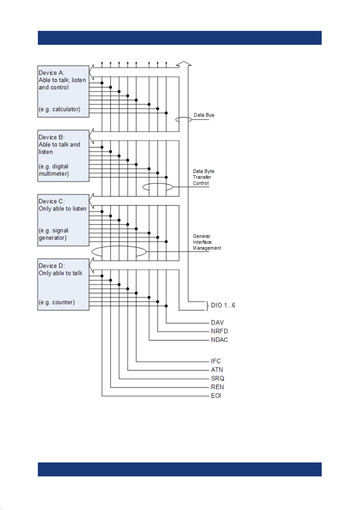
R&S®FPS
Controlling the R&S FPS Remotely
Remote Control Interfaces and Protocols
Figure 7-1: Communication lines used by the GPIB interface
67Getting Started 1319.3362.02 ─ 10

R&S®FPS
Controlling the R&S FPS Remotely
Remote Control Interfaces and Protocols
Universal Commands
Universal commands are encoded in the range 10 through 1F hex. They affect all
instruments connected to the bus and do not require addressing.
Command Effect on the instrument
DCL (Device Clear) Aborts the processing of the commands just received and sets the
command processing software to a defined initial state. Does not
change the instrument settings.
IFC (Interface Clear) *) Resets the interfaces to the default setting.
LLO (Local Lockout) The "Local" softkey is disabled. Manual operation is no longer
available until GTL is executed.
SPE (Serial Poll Enable) Ready for serial poll.
SPD (Serial Poll Disable) End of serial poll.
PPU (Parallel Poll Unconfigure)
*) IFC is not a real universal command, it is sent via a separate line; however, it also affects all
instruments connected to the bus and does not require addressing
End of the parallel-poll state.
Addressed Commands
Addressed commands are encoded in the range 00 through 0F hex. They only
affect instruments addressed as listeners.
Command Effect on the instrument
GET (Group Execute Trigger) Triggers a previously active instrument function (e.g. a
sweep). The effect of the command is the same as with
that of a pulse at the external trigger signal input.
GTL (Go to Local) Transition to the "local" state (manual control).
GTR (Go to Remote) Transition to the "remote" state (remote control).
PPC (Parallel Poll Configure) Configures the instrument for parallel poll.
SDC (Selected Device Clear) Aborts the processing of the commands just received and
sets the command processing software to a defined initial
state. Does not change the instrument setting.
7.1.3 USB Interface
For remote control via the USB connection, the PC and the instrument must be
connected via the USB type B interface. A USB connection requires the VISA
library to be installed. VISA detects and configures the R&S instrument automati-
68Getting Started 1319.3362.02 ─ 10

R&S®FPS
Controlling the R&S FPS Remotely
Remote Control Interfaces and Protocols
cally when the USB connection is established. You do not have to enter an
address string or install a separate driver.
USB address
The used USB address string is:
USB::<vendor ID>::<product ID>::<serial number>[::INSTR]
where:
●
<vendor ID> is the vendor ID for Rohde & Schwarz (0x0AAD)
●
<product ID> is the product ID for the Rohde & Schwarz instrument
●
<serial number> is the individual serial number on the rear of the instrument
Table 7-2: Product IDs for R&S FPS
Instrument model Product ID
FPS4 F9
FPS7 FA
FPS13 FB
FPS30 FC
FPS40 FD
Example:
USB::0x0AAD::0x00FB::100001::INSTR
0x0AAD is the vendor ID for Rohde & Schwarz
0x00FB is the product ID for the R&S FPS13
100001 is the serial number of the particular instrument
7.1.4 VISA Libraries
VISA is a standardized software interface library providing input and output functions to communicate with instruments. The I/O channel (LAN or TCP/IP, USB, ...)
is selected at initialization time by one of the following:
●
The channel–specific address string ("VISA resource string") indicated in
Table 7-1
●
An appropriately defined VISA alias (short name).
69Getting Started 1319.3362.02 ─ 10

R&S®FPS
A VISA installation is a prerequisite for remote control using the following interfaces:
●
Chapter 7.1.2, "GPIB Interface (IEC 625/IEEE 418 Bus Interface)",
on page 65
●
Chapter 7.1.1, "LAN Interface", on page 59
●
Chapter 7.1.3, "USB Interface", on page 68
For more information about VISA, refer to the user documentation.
Controlling the R&S FPS Remotely
How to Configure a Network
7.2 How to Configure a Network
Risk of network failure
Consult your network administrator before performing the following tasks:
●
Connecting the instrument to the network
●
Configuring the network
●
Changing IP addresses
●
Exchanging hardware
Errors can affect the entire network.
The R&S FPS is equipped with a network interface and can be connected to an
Ethernet LAN (local area network). Provided the appropriate rights have been
assigned by the network administrator and the Windows 10 firewall configuration
is adapted accordingly, the interface can be used, for example:
●
To transfer data between a controller and the tester, e.g. in order to run a
remote control program; see the "Remote Control" chapter in the R&S FPS
User Manual
●
To access or control the measurement from a remote computer using the
"Remote Desktop" application (or a similar tool); see Chapter 7.6, "How to Set
Up Remote Desktop", on page 82
●
To connect external network devices (e.g. printers)
●
To transfer data from a remote computer and back, e.g. using network folders
70Getting Started 1319.3362.02 ─ 10

R&S®FPS
A precondition for operating or monitoring the R&S FPS remotely is that it is connected to a LAN network or a PC connected to the GPIB interface. This is described here.
Windows Firewall Settings
A firewall protects an instrument by preventing unauthorized users from
gaining access to it through a network. Rohde & Schwarz highly recommends the use of the firewall on your instrument. R&S instruments are shipped with the Windows firewall enabled and preconfigured in such a way that
all ports and connections for remote control are enabled. For more details
on firewall configuration see the Rohde & Schwarz White Paper 1DC01:
Malware Protection and the Windows 10 help system.
Controlling the R&S FPS Remotely
How to Configure a Network
7.2.1 How to Connect the Instrument to the Network
There are two methods to establish a LAN connection to the instrument:
●
A non-dedicated network (Ethernet) connection from the instrument to an
existing network made with an ordinary RJ-45 network cable. The instrument
is assigned an IP address and can coexist with a computer and with other
hosts on the same network.
●
A dedicated network connection (Point-to-point connection) between the
instrument and a single computer made with a (crossover) RJ-45 network
cable. The computer must be equipped with a network adapter and is directly
connected to the instrument. The use of hubs, switches, or gateways is not
required, however, data transfer is still performed using the TCP/IP protocol.
An IP address has to be assigned to the instrument and the computer, see
Chapter 7.2.2, "How to Assign the IP Address", on page 72.
Note: As the R&S FPS uses a 1 GBit LAN, a crossover cable is not necessary
(due to Auto-MDI(X) functionality).
► To establish a non-dedicated network connection, connect a commercial
RJ-45 cable to one of the LAN ports.
To establish a dedicated connection, connect a (crossover) RJ-45 cable
between the instrument and a single PC.
If the instrument is connected to the LAN, Windows 10 automatically detects the
network connection and activates the required drivers.
71Getting Started 1319.3362.02 ─ 10

R&S®FPS
The network card can be operated with a 1 GBit Ethernet IEEE 802.3u interface.
Controlling the R&S FPS Remotely
How to Configure a Network
7.2.2 How to Assign the IP Address
Depending on the network capacities, the TCP/IP address information for the
instrument can be obtained in different ways.
●
If the network supports dynamic TCP/IP configuration using the Dynamic Host
Configuration Protocol (DHCP), all address information can be assigned automatically.
●
If the network does not support DHCP, or if the instrument is set to use alternate TCP/IP configuration, the addresses must be set manually.
By default, the instrument is configured to use dynamic TCP/IP configuration and
obtain all address information automatically. This means that it is safe to establish
a physical connection to the LAN without any previous instrument configuration.
Risk of network errors
Connection errors can affect the entire network. If your network does not
support DHCP, or if you choose to disable dynamic TCP/IP configuration,
you must assign valid address information before connecting the instrument
to the LAN. Contact your network administrator to obtain a valid IP address.
Assigning the IP address directly on the R&S FPS
1. In the R&S FPS's mini display, navigate to "Network" > "DHCP".
2. If DHCP is "Off", you must enter the IP address manually, as described in the
following steps.
Note: When DHCP is changed from "On" to "Off", the previously set IP
address and subnet mask are retrieved.
If DHCP is "On", the IP address of the DHCP server is obtained automatically.
The configuration is saved, and you are prompted to restart the instrument.
You can skip the remaining steps.
Note: When a DHCP server is used, a new IP address may be assigned each
time the instrument is restarted. This address must first be determined on the
instrument itself. Thus, when using a DHCP server, it is recommended that
you use the permanent computer name, which determines the address via the
DNS server.
72Getting Started 1319.3362.02 ─ 10

R&S®FPS
3. In the R&S FPS's mini display, navigate to "Network" > "IP".
4. Enter the "IP Address", for example 10.0.0.10. The IP address consists of four
number blocks separated by dots. Every block contains 3 numbers in maximum.
Enter the required address: Use the <Up Arrow> and <Down Arrow> keys to
scroll through the digits 1-10 and the <Left Arrow> and <Right Arrow> keys to
move between the individual numbers and blocks.
5. Enter the "Subnet Mask", for example 255.255.255.0. The subnet mask consists of four number blocks separated by dots. Every block contains 3 numbers in maximum.
6. Press the [Enter] key to store the entry and exit the edit mode.
7. In the R&S FPS's mini display, navigate to "System commands" > "Reboot
system" to restart the system.
Controlling the R&S FPS Remotely
How to Configure a Network
7.2.3 How to Configure the LAN Using the Web Browser Inter-
face
The instrument's "LAN" web browser interface works correctly with all W3C compliant browsers.
If no external monitor is connected to the R&S FPS, an additional driver is
required on the instrument in order to control the R&S FPS via its web
browser interface. If the driver is not available, the browser shows only a
black screen.
Download the TightVNC DFMirage driver from the official TightVNC website (http://www.tightvnc.com/download.php) and install it on the R&S FPS
as described on the website.
The current R&S FPS firmware was tested with the TightVNC DFMirage
driver version 2.0.301.
► In the web browser, open the http://<instrument-hostname> or
http://<instrument-ip-address> page, e.g. http://10.113.10.203.
The default password to change "LAN" configurations is LxiWebIfc.
The "Instrument Home Page" (welcome page) opens.
73Getting Started 1319.3362.02 ─ 10
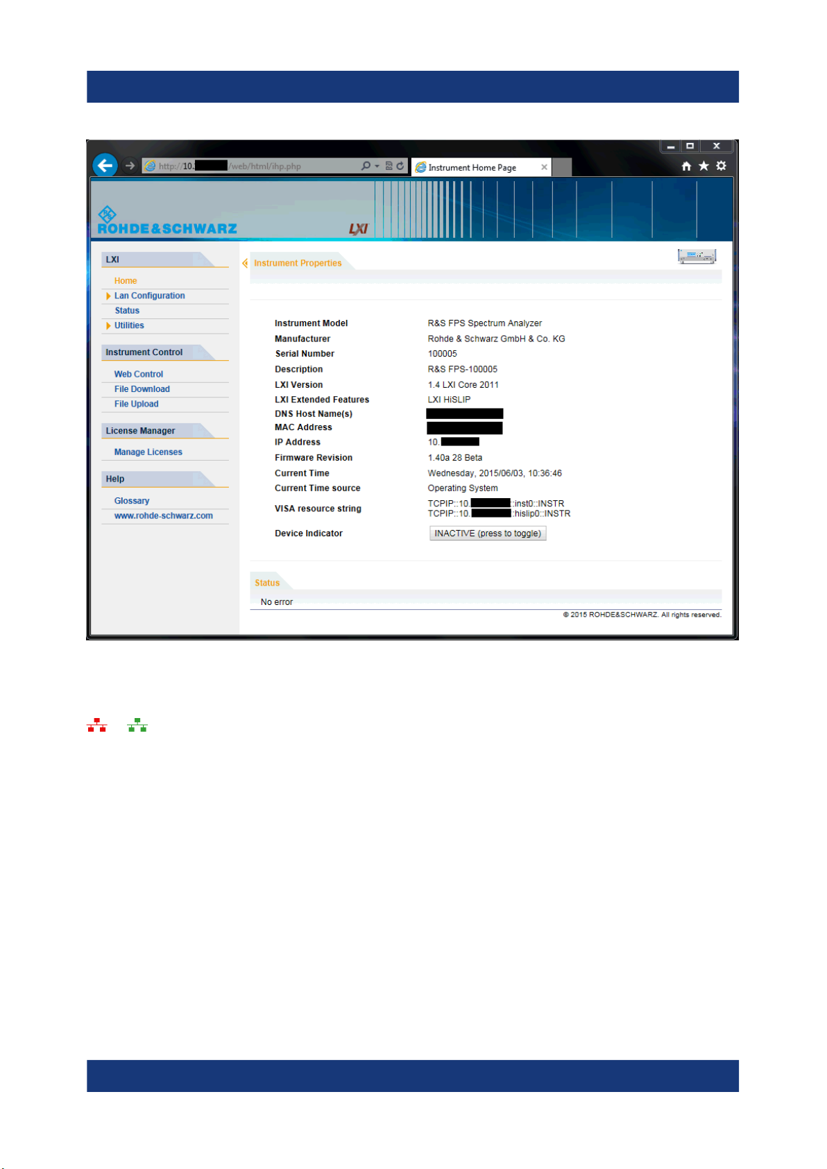
R&S®FPS
Controlling the R&S FPS Remotely
How to Configure a Network
The instrument home page displays device information, including the VISA
resource string, in read-only format.
► Press the "Device Indicator" button on the "Instrument Home Page" to activate
or deactivate the "LAN" status icon on the status bar of the R&S FPS. A green
"LAN" status symbol indicates that a LAN connection has been established; a
red symbol indicates an error, for example, that no LAN cable is connected.
When a device is connecting to the instrument, the "LAN" icon blinks. The
"Device Indicator" setting is not password-protected.
The most important control elements in the navigation pane of the browser interface are the following:
●
"LAN Configuration" opens the menu with configuration pages.
●
"Status" displays information about the "LAN" status of the instrument.
74Getting Started 1319.3362.02 ─ 10

R&S®FPS
7.2.3.1 LAN Configuration
The LAN configuration consists of three parts:
●
"IP configuration" provides all mandatory LAN parameters.
●
"Advanced LAN Configuration" provides further LAN settings.
●
"Ping Client" provides the ping utility to verify the connection between the
instrument and other devices.
IP Configuration
The "LAN Configuration > IP configuration" web page displays all mandatory LAN
parameters and allows their modification.
The "TCP/IP Mode" configuration field controls how the IP address for the instrument gets assigned (see also Chapter 7.2.2, "How to Assign the IP Address",
on page 72).
Controlling the R&S FPS Remotely
How to Configure a Network
For the manual configuration mode, the static IP address, subnet mask, and
default gateway are used to configure the LAN. The automatic configuration
mode uses DHCP server or Dynamic Link Local Addressing (Automatic IP) to
obtain the instrument IP address.
Changing the LAN configuration is password-protected. The default password is LxiWebIfc (notice upper and lower case characters).
Advanced LAN Configuration
The "LAN Configuration > Advanced LAN Configuration" parameters are used as
follows:
●
The "Negotiation" configuration field provides different Ethernet speed and
duplex mode settings. In general, the "Auto Detect" mode is sufficient.
●
"ICMP Ping" must be enabled to use the ping utility.
●
"VXI-11" is the protocol that is used to detect the instrument in the LAN.
●
mDNS and DNS-SD are two additional protocols: Multicast DNS and DNS
Service Discovery. They are used for device communication in zero configuration networks working without DNS and DHCP
Ping Client
Ping is a utility that verifies the connection between the instrument and another
device. The ping command uses the ICMP echo request and echo reply packets
75Getting Started 1319.3362.02 ─ 10

R&S®FPS
to determine whether the LAN connection is functional. Ping is useful for diagnosing IP network or router failures. The ping utility is not password-protected.
To initiate a ping between the instrument and a second connected device:
1. Enable "ICMP Ping" on the "Advanced LAN Configuration" page (enabled
after an LCI).
2. Enter the IP address of the second device without the ping command and
without any further parameters into the "Destination Address" field (e.g.
10.113.10.203).
3. Select "Submit".
Controlling the R&S FPS Remotely
How to Log on to the Network
7.2.4 How to Change the GPIB Instrument Address
In order to operate the instrument via remote control, it must be addressed using
the GPIB address. The remote control address is factory-set to 20, but it can be
changed if it does not fit in the network environment. For remote control,
addresses 0 through 30 are allowed. The GPIB address is maintained after a
reset of the instrument settings.
To change the GPIB address
1. In the R&S FPS's mini display menu, navigate to "GPIB" > "GPIB address"
and press the [Enter] key.
2. Enter the required address: Use the <Up Arrow> and <Down Arrow> keys to
scroll through the digits 1-10 and the <Left Arrow> and <Right Arrow> keys to
move between the first and second digits.
3. Press the [Enter] key again to store the entry and exit the edit mode.
Remote command:
SYST:COMM:GPIB:ADDR 18
7.3 How to Log on to the Network
Windows 10 requires that users identify themselves by entering a user name and
password in a login window. You can set up two types of user accounts, either an
76Getting Started 1319.3362.02 ─ 10

R&S®FPS
administrator account with unrestricted access to the computer/domain or a standard user account with limited access. The instrument provides an auto-login
function for the administrator account, i.e. login with unrestricted access is carried
out automatically in the background. By default, the user name for the administrator account is "Instrument", and the user name for the standard user account is
"NormalUser". In both cases the initial password is "894129". You can change the
password in Windows 10 for any user at any time. Some administrative tasks
require administrator rights (e.g. firmware updates or the configuration of a LAN
network).
At the same time you log on to the operating system, you are automatically logged on to the network. As a prerequisite, the user name and the password must
be identical on the instrument and on the network.
Controlling the R&S FPS Remotely
How to Log on to the Network
7.3.1 How to Create Users
After the software for the network has been installed, the instrument issues an
error message the next time it is switched on because there is no user named
"instrument" (= default user ID for Windows 10 automatic login) in the network.
Thus, a matching user must be created in the R&S FPS and in the network, the
password must be adapted to the network password, and the automatic login
mechanism must then be deactivated.
In order to configure users for the R&S FPS, a controller pc or an external
monitor, mouse and keyboard must be connected to the R&S FPS. See
Chapter 7.6, "How to Set Up Remote Desktop", on page 82.
The network administrator is responsible for creating new users in the network. A
new user can be created on the instrument using the "User Account" dialog box:
1.
Select the "Windows" icon in the toolbar to access the operating system of the
R&S FPS.
2. In the "Start" menu, select "Control Panel" and then select "User Accounts."
3. Select "Give other users access to this computer" and then "Add".
The "Add New User" dialog box is displayed.
4. Enter the name of the new user in the text field and select "Next".
77Getting Started 1319.3362.02 ─ 10

R&S®FPS
5. Define the level of access you want to allow the new user:
● Select "Standard" to create an account with limited rights.
● Select "Administrator" to create an account with administrator rights.
Note: Full firmware functionality requires administrator rights.
6. Select the "Finish" button.
The new user is created.
Controlling the R&S FPS Remotely
How to Log on to the Network
7.3.2 How to Change the User Password
In order to change the user passwords for the R&S FPS, a controller pc or
an external monitor, mouse and keyboard must be connected to the
R&S FPS. See Chapter 7.6, "How to Set Up Remote Desktop",
on page 82.
After the new user has been created on the instrument, the password must be
adapted to the network password. This is also done using the "User Accounts"
dialog box.
1.
Select the "Windows" icon in the toolbar to access the operating system of the
R&S FPS.
2. Select [Ctrl + Alt + Delete], then select "Change a password".
3. Enter the user account name.
4. Enter the old password.
5. Enter the new password in the upper text line and repeat it in the following
line.
6. Select [Enter].
The new password is now active.
78Getting Started 1319.3362.02 ─ 10

R&S®FPS
Controlling the R&S FPS Remotely
How to Log on to the Network
7.3.3 How to Configure the Automatic Login Mechanism
In order to activate or deactivate the automatic login mechanism on the
R&S FPS, a controller pc or an external monitor, mouse and keyboard must
be connected to the R&S FPS. See Chapter 7.6, "How to Set Up Remote
Desktop", on page 82.
Adapting the auto-login function to a new password
If you change the password that is used during auto-login, this function no longer
works. Adapt the settings for the auto-login function first.
If the SecureUser or the NormalUser are enabled, those passwords are used for
autologin. In that case, if you change any of the passwords, the autologin function
must be adapted each time you change the user account.
1. Open the C:\R_S\INSTR\USER\user\AUTOLOGIN.REG file in any text editor (e.g. Notepad).
2. In the line "DefaultPassword"="894129", replace the default password
(894129) by the new password for automatic login.
3. Save the changes to the file.
4. In the Windows "Start" menu, select "Run".
The "Run" dialog box is displayed.
5. Enter the command C:\R_S\INSTR\USER\user\AUTOLOGIN.REG.
6. Press the [ENTER] key to confirm.
The auto-login function is reactivated with the changed password. It will be
applied the next time the instrument is switched on.
Switching users when using the auto-login function
Which user account is used is defined during login. If auto-login is active, the
login window is not displayed. However, you can switch the user account to be
used even when the auto-login function is active.
1. Select the "Windows" icon in the toolbar to access the operating system of the
R&S FPS (see also "To access the "Start" menu" on page 28).
79Getting Started 1319.3362.02 ─ 10

R&S®FPS
How to Share Directories (only with Microsoft Networks)
2. Press [CTRL] + [ALT] + [DEL], then select "Sign out".
The "Login" dialog box is displayed, in which you can enter the different user
account name and password.
Deactivating the auto-login function
When shipped, the instrument is already configured to automatically log on the
"instrument" user under Windows 10. To deactivate the auto-login function, perform the following steps:
1. In the "Start" menu, select "Run".
The "Run" dialog box is displayed.
2. Enter the command C:\R_S\INSTR\USER\user\NO_AUTOLOGIN.REG.
3. Press the [ENTER] key to confirm.
The auto-login function is deactivated. The next time you switch on the instrument, you are prompted to enter your user name and password before the
firmware is started.
Controlling the R&S FPS Remotely
Reactivating the auto-login function
To reactivate the auto-login function after manually deactivating it, perform the following steps:
1. In the "Start" menu, select "Run".
The "Run" dialog box is displayed.
2. Enter the command C:\R_S\INSTR\USER\user\AUTOLOGIN.REG.
3. Press the [ENTER] key to confirm.
The auto-login function is reactivated. It will be applied the next time the
instrument is switched on.
7.4 How to Share Directories (only with Microsoft
Networks)
Sharing directories makes data available for other users. This is only possible in
Microsoft networks. Sharing is a property of a file or directory.
80Getting Started 1319.3362.02 ─ 10

R&S®FPS
How to Start a Remote Control Session from a PC
In order to configure shared directories on the R&S FPS, a controller pc or
an external monitor, mouse and keyboard must be connected to the
R&S FPS. See Chapter 7.6, "How to Set Up Remote Desktop",
on page 82.
1.
Select the "Windows" icon in the toolbar to access the operating system of the
R&S FPS.
2. In the "Start" menu, select "Programs", "Accessories" and then select "Windows Explorer".
3. Select the desired folder with the right mouse button.
4. In the context menu, select "Sharing with > Specific people".
The dialog box for sharing a directory is displayed.
Controlling the R&S FPS Remotely
5. Select a user from the list or add a new name and select the "Add" button.
6. Select the "Share" button.
7. Select "Done" to close the dialog box.
The drive is shared and can be accessed by the selected users.
7.5 How to Start a Remote Control Session from a
PC
When you switch on the instrument, it is always in manual operation state ("local"
state) and can be operated via Remote Desktop from an external PC.
1. Send an addressed command (GTR - Go to Remote) from a controller to the
instrument.
The instrument is switched to remote control ("remote" state). Operation via
the soft front panel (on the Remote Desktop) is disabled. (The keys on the
R&S FPS remain enabled.) The instrument remains in the remote state until it
is reset to the manual state via the remote control interface.
Switching from manual operation to remote control and vice versa does not
affect the other instrument settings.
81Getting Started 1319.3362.02 ─ 10

R&S®FPS
2. To obtain optimum performance during remote control, send the
SYSTem:DISPlay:UPDate OFF command to hide the display of results and
diagrams on the controller PC or external monitor (default setting in remote
control).
3. To enable manual operation via the soft front panel on the Remote Desktop
again, switch the instrument to local mode using the remote command GTL
(Go to Local), that is, deactivate the REN line of the remote control interface.
Controlling the R&S FPS Remotely
How to Set Up Remote Desktop
7.6 How to Set Up Remote Desktop
Remote Desktop is a Windows application which can be used to access and control the instrument from a remote computer through a LAN connection. While the
instrument is in operation, the instrument uses the display on the remote computer, and Remote Desktop provides access to all of the applications, files, and
network resources of the instrument. Thus, remote operation of the R&S FPS is
possible.
With Windows 10, Remote Desktop Client is part of the operating system. For
other versions of Windows, Microsoft offers the Remote Desktop Client as an
add-on.
This section provides basic instructions on setting up the Remote Desktop for the
R&S FPS. For details refer to the Windows 10 operating system documentation.
7.6.1 How to Configure the R&S FPS for Remote Operation via
Remote Desktop
By default, the R&S FPS is configured to allow Remote Desktop access by
any user (except for the "SecureUser", see Chapter 7.6.5, "How to Add or
Remove Users to the Remote Desktop Users Group", on page 88).
To change the settings for remote operation, you must connect an external monitor, mouse and keyboard, or connect a controller PC and set up a Remote Desktop connection with the default settings as described in Chapter 7.6.3, "How to
Start and Close the Remote Desktop", on page 86.
82Getting Started 1319.3362.02 ─ 10

R&S®FPS
To change the settings for Remote Desktop access
1.
Select the "Windows" icon in the toolbar to access the operating system of the
R&S FPS.
2. In the "Start" menu, select the "Control Panel" and then "System and Security".
3. In the "System" area, select "Allow remote access".
Controlling the R&S FPS Remotely
How to Set Up Remote Desktop
4. In the "Remote" tab, in the "Remote Desktop" area, activate the "Allow connections from computers running Remote Desktop" option.
5. Define which users are to be given access to the R&S FPS via Remote Desktop.
If the secure user mode is deactivated, the "SecureUser" account is also
deactivated. Thus, the procedure described here will not work for the "SecureUser". Instead, see Chapter 7.6.5, "How to Add or Remove Users to the
Remote Desktop Users Group", on page 88.
Note: Administrator user accounts (e.g. "Instrument") are automatically
enabled for Remote Desktop.
a) Select the "Select Users" button.
b) Select the users or create new user accounts as described in Chap-
ter 7.3.1, "How to Create Users", on page 77.
c) Select "OK" to confirm the settings.
83Getting Started 1319.3362.02 ─ 10

R&S®FPS
6. The R&S FPS is now ready for connection setup with the Remote Desktop
program of the controller.
Controlling the R&S FPS Remotely
How to Set Up Remote Desktop
7.6.2 How to Configure the Controller
Remote Desktop Client
With Windows 10, Remote Desktop Client is part of the operating system
and can be accessed via "Start > Programs > Accessories > Remote Desktop Connection".
For other versions of Windows, Microsoft offers the Remote Desktop Client
as an add-on.
1. In the "Start" menu of the controller, select "All Programs > Accessories >
Remote Desktop Connection".
The "Remote Desktop Connection" dialog box is displayed.
2. Select the "Options >>" button.
The dialog box is expanded to display the configuration data.
3. Open the "Experience" tab.
The settings on this tab are used to select and optimize the connection speed.
84Getting Started 1319.3362.02 ─ 10

R&S®FPS
4. In the list, select the appropriate connection (for example: LAN (10 Mbps or
higher)).
Depending on your selection (and how powerful the connection is), the
options are activated or deactivated.
5. To improve the performance, you can deactivate the "Desktop background",
"Show window contents while dragging" and "Menu and window animation"
options.
6. Open the "Local Resources" tab to enable printers, local drives and serial
interfaces.
7. If you will need to access drives of the controller from the R&S FPS (e.g. in
order to store settings or to copy files from the controller to the R&S FPS),
activate the "Disk drives" option.
Windows will then map drives of the controller to the corresponding network
drives.
Controlling the R&S FPS Remotely
How to Set Up Remote Desktop
8. To use printers connected to the controller while accessing them from the
R&S FPS, activate the "Printers" options. Do not change the remaining settings.
9. Open the "Display" tab.
The options to configure the R&S FPS screen display are displayed.
10.Under "Remote desktop size", you can set the size of the R&S FPS window
on the desktop of the controller.
11. Under "Colors", do not change the settings.
12.Set the "Display the connection bar when I use the full screen" option:
If activated, a bar showing the network address of the R&S FPS will appear at
the top edge of the screen. You can use this bar to reduce, minimize or close
the window.
If deactivated, the only way you can return to the controller desktop from the
R&S FPS screen in full screen mode is to select "Disconnect" from the "Start"
menu.
85Getting Started 1319.3362.02 ─ 10

R&S®FPS
Controlling the R&S FPS Remotely
How to Set Up Remote Desktop
7.6.3 How to Start and Close the Remote Desktop
To set up a connection from the controller to the R&S FPS
1. On the controller, in the "Remote Desktop Connection" dialog box (see Chap-
ter 7.6.2, "How to Configure the Controller", on page 84), open the "General"
tab.
2. In the "Computer" field, enter the IP address of the R&S FPS (see Chap-
ter 7.2.2, "How to Assign the IP Address", on page 72 to determine the IP
address).
In the "User name" field, enter instrument to log in as an administrator, or Nor-
mal User to log in as a standard user.
In the "Password" field, enter 894129.
3. To save the connection configuration for later use:
a) Select the "Save As" button.
The "Save As" dialog box is displayed.
b) Enter the name for the connection information (*.RDP).
4. To load an existing connection configuration:
a) Select the "Open" button.
The "Open" dialog box is displayed.
b) Select the *.RDP file.
5. Select the "Connect" button.
The connection is set up.
6. If the "Disk drives" option is activated on the "Local Resources" tab, a warning
is displayed indicating that the drives are enabled for access from the
R&S FPS.
Select "OK" to confirm the warning.
7. After a few moments, the R&S FPS screen is displayed and manual operation
is possible.
For details on manual operation see Chapter 8, "Operating the Instrument in
Manual Mode", on page 95.
8. If a dark screen appears or a dark square appears in the upper left-hand corner of the screen, you must restart the R&S FPS in order to see the modified
screen resolution.
86Getting Started 1319.3362.02 ─ 10

R&S®FPS
Controlling the R&S FPS Remotely
How to Set Up Remote Desktop
●
Select the key combination [ALT] + [F4].
●
The R&S FPS firmware is shut down, which may take a few
seconds.
●
On the desktop, double-click the "Analyzer" icon.
The firmware restarts and then automatically opens the graphical user interface from which you can access all instrument functions and settings.
For more information see Chapter 8.1.3, "Front Panels", on page 98.
9. After the connection is established, the R&S FPS screen is displayed in the
"Remote Desktop" application window.
To terminate Remote Desktop control
► On the controller, close the "Remote Desktop" window at any time.
The connection to the R&S FPS is terminated.
87Getting Started 1319.3362.02 ─ 10

R&S®FPS
Restoring the connection to the R&S FPS
Follow the instructions above for setting up a connection to the R&S FPS. If the
connection is terminated and then restored, the R&S FPS remains in the same
state.
Controlling the R&S FPS Remotely
How to Set Up Remote Desktop
7.6.4 How to Shut Down the R&S FPS via Remote Desktop
1.
Select the "Windows" icon in the toolbar to access the operating system of the
R&S FPS.
2. In the "Start" menu, enter cmd to start a command prompt window.
3. In the command prompt window, enter shutdown /s.
The connection with the controller is terminated and the R&S FPS is shut
down.
7.6.5 How to Add or Remove Users to the Remote Desktop
Users Group
Only users in the Remote Desktop Users Group are allowed to connect to the
R&S FPS via Remote Desktop. You can add the users to this group directly when
you allow remote access on the R&S FPS, as described in Chapter 7.6, "How to
Set Up Remote Desktop", on page 82. Furthermore, you can add or remove
users to this group at any time.
In order to add or remove users to the Remote Desktop users group for the
R&S FPS, a controller pc or an external monitor, mouse and keyboard must
be connected to the R&S FPS. See Chapter 7.6, "How to Set Up Remote
Desktop", on page 82.
88Getting Started 1319.3362.02 ─ 10

R&S®FPS
Secure User Mode
For security reasons, the "SecureUser" used in secure user mode is not
allowed Remote Desktop access to the R&S FPS by default (see Chap-
ter 4.15, "Protecting Data Using the Secure User Mode", on page 33). You
must explicitely add the "SecureUser" to the Remote Desktop group. If you
do not allow this user RemoteDesktop access, the "SecureUser" will only be
able to operate the R&S FPS using remote commands or via the mini display.
1. If necessary, disable the "SecureUser" on the R&S FPS (mini display: "System commands > Disable SecureUser").
2. Login using the administrator ("Instrument" user) account.
3. Start a RemoteDesktop connection to the R&S FPS as described in "To set up
a connection from the controller to the R&S FPS" on page 86.
Controlling the R&S FPS Remotely
How to Set Up Remote Desktop
4.
Select the "Windows" icon in the toolbar to access the operating system of the
R&S FPS.
5. Open the Windows Explorer.
6. Select the directory:
Control Panel\All Control Panel Items\
Administrative Tools.
7. Double-click "Computer Management".
8. In the "Computer Management" dialog box, select "Local Users and Groups
\Users" on the left side.
89Getting Started 1319.3362.02 ─ 10

R&S®FPS
9. Double-click the user to be added, for example: "SecureUser".
Controlling the R&S FPS Remotely
How to Set Up Remote Desktop
10.In the "SecureUser Properties" dialog box, switch to the "Member of" tab and
click "Add".
11. In the "Select Groups" dialog box, enter the "Remote Desktop Users" group
and select "OK".
90Getting Started 1319.3362.02 ─ 10

R&S®FPS
How to Control the R&S FPS via the Web Browser Interface
12.Select "Apply".
13.Select "OK" and close all dialog boxes.
14.Reboot the R&S FPS firmware so the changes become effective.
The new user (e.g. "SecureUser") should now be able to access the R&S FPS
via RemoteDesktop.
Controlling the R&S FPS Remotely
7.7 How to Control the R&S FPS via the Web
Browser Interface
Via the LAN web browser interface to the R&S FPS, one or more users can control the instrument remotely from another PC without additional installation. Most
instrument controls are available via the front panel simulation. File upload and
download between the instrument and the remote PC is also available.
If no external monitor is connected to the R&S FPS, an additional driver is
required on the instrument in order to control the R&S FPS via its web
browser interface. If the driver is not available, the browser shows only a
black screen.
Download the TightVNC DFMirage driver from the official TightVNC website (http://www.tightvnc.com/download.php) and install it on the R&S FPS
as described on the website.
The current R&S FPS firmware was tested with the TightVNC DFMirage
driver version 2.0.301.
91Getting Started 1319.3362.02 ─ 10

R&S®FPS
How to Control the R&S FPS via the Web Browser Interface
To access the R&S FPS via the web browser interface
1. Start a web browser that supports html5 (W3C compliant).
2. Enter the IP address of the R&S FPS in the browser's address bar.
The R&S FPS's Welcome page is displayed.
3. In the navigation pane, select "Instrument Control > Web Control".
The instrument's display is shown in a new browser window, with a software
front panel displayed beside or below it.
4. Use the mouse cursor to access the functionality in the software front panel or
in the display as you would directly on the instrument's front panel.
To exchange files with the R&S FPS
You can download files, for example stored measurement data, from the
R&S FPS to the remote PC, or upload files, for example limit line definitions, from
the PC to the R&S FPS.
Controlling the R&S FPS Remotely
1. In the web browser, select the Welcome page window.
2. In the navigation pane, select "Instrument Control" > "File Upload" or "File
Download".
92Getting Started 1319.3362.02 ─ 10

R&S®FPS
How to Deactivate the Web Browser Interface
The most commonly used folders on the instrument are displayed, for example those that contain user data, as well as the top-most My Computer folder,
from which you can access all other folders on the instrument.
3. To download a file from the R&S FPS, select the file from the displayed folders
and then select "Download File".
4. To upload a file to the R&S FPS:
a) From the displayed folders in the web browser window, select the folder on
the R&S FPS to which you want to copy a file.
b) Under "File to Upload", select "Browse" to open a file selection dialog box
and select the required file on the PC.
c) Select "Upload" to copy the file from the PC to the defined folder on the
R&S FPS.
Controlling the R&S FPS Remotely
7.8 How to Deactivate the Web Browser Interface
If you want to prevent other users in the LAN from accessing or operating the
R&S FPS via its LAN web browser interface, you must deactivate this function.
Note that after a firmware update the function is automatically active again
until you deactivate it manually.
To deactivate the LAN web browser interface
1.
Select the "Windows" icon in the toolbar to access the operating system.
2. In the "Start" menu, select "Control Panel".
3. Select "System and Security" > "Administrative Tools".
4. From the list on the right, select "Services".
5. From the list of local services, select "R&S TightVNC Server".
93Getting Started 1319.3362.02 ─ 10

R&S®FPS
Controlling the R&S FPS Remotely
How to Deactivate the Web Browser Interface
6. Set "Startup type" to "Disabled".
7. Select "Stop".
8. Select "Apply".
The next time a user enters the IP address of the instrument in a web
browser, an error message is displayed:
Failed to connect to server (code. 1006)
94Getting Started 1319.3362.02 ─ 10

R&S®FPS
Graphical User Interface Elements (Soft Front Panel)
Operating the Instrument in Manual Mode
8 Operating the Instrument in Manual
Mode
The R&S FPS is completely remote-controlled; it does not provide a display for
manual measurement control. The mini display on the front panel of the R&S FPS
allows only for very basic instrument configuration (see Chapter 6, "Mini Display",
on page 47).
However, although the R&S FPS does not have a built-in display for manual measurement control, it is possible to operate it interactively in manual mode using a
graphical user interface on an external monitor or a controller PC.
It is recommended that you use the manual mode initially to get familiar with the
instrument and its functions before using it in pure remote mode. Thus, this section describes in detail how to operate the instrument manually using a controller
PC and mouse, or an external monitor, mouse and keyboard. It describes what
kind of information is displayed in the diagram area, how to use the soft front
panel keys and other interface elements, and how to use the Online Help.
● Graphical User Interface Elements (Soft Front Panel)....................................95
● Understanding the Display Information......................................................... 106
● Changing the Focus...................................................................................... 115
● Entering Data.................................................................................................116
● Displaying Results.........................................................................................116
● Getting Help.................................................................................................. 123
8.1 Graphical User Interface Elements (Soft Front
Panel)
All tasks necessary to operate the instrument can be performed using the graphical user interface provided by the soft front panel, a virtual front panel displayed
on the external monitor or the Remote Desktop.
All measurement results are displayed. Additionally, the display provides status
and setting information, allows you to switch between various measurement
tasks, and provides access to all measurement functions.
95Getting Started 1319.3362.02 ─ 10

R&S®FPS
Operating the Instrument in Manual Mode
Graphical User Interface Elements (Soft Front Panel)
1
8
2
3 6 74 5
9
10
Figure 8-1: Graphical user interface elements in the R&S FPS's soft front panel
1 = Toolbar with standard application functions, e.g. print, save/open file etc.
2 = Tabs for individual measurement channels
3 = Channel bar for firmware and measurement settings
4 = Window title bar with diagram-specific (trace) information
5 = Measurement results area
6 = Input field for measurement setting
7 = Softkeys for function access
8 = Diagram footer with diagram-specific information, depending on application
9 = Instrument status bar with error messages, progress bar and date/time display
10 = Front panel with keys, keypad, navigation elements
8.1.1 Toolbar
Standard functions can be performed via the icons in the toolbar at the top of the
screen.
96Getting Started 1319.3362.02 ─ 10

R&S®FPS
Operating the Instrument in Manual Mode
Graphical User Interface Elements (Soft Front Panel)
You can hide the toolbar display to enlarge the display area for the measurement results ("Setup > Display > Displayed Items"). See the R&S FPS
user manual for details.
The following functions are available:
Table 8-1: Standard application functions in the toolbar
Icon Description
Windows: displays the Windows "Start" menu and task bar
Open: opens a file from the instrument ("Save/Recall" menu)
Store: stores data on the instrument ("Save/Recall" menu)
Print: defines print settings ("Print" menu)
Undo: reverts last operation
Redo: repeats previously reverted operation
Selection mode: the cursor can be used to select (and move) markers in a zoomed
display
Zoom mode: displays a dotted rectangle in the diagram that can be expanded to
define the zoom area
Multiple zoom mode: multiple zoom areas can be defined for the same diagram
Zoom off: displays the diagram in its original size
SmartGrid: activates "SmartGrid" mode to configure the screen layout
Sequencer: opens the "Sequencer" menu to perform consecutive measurements
Help (+ Select): allows you to select an object for which context-specific help is displayed
AL Analysis line (MSRA mode only): opens a dialog box to display and position an analy-
sis line in MSRA measurements (see R&S FPS MSRA user manual)
97Getting Started 1319.3362.02 ─ 10

R&S®FPS
Operating the Instrument in Manual Mode
Graphical User Interface Elements (Soft Front Panel)
Icon Description
Help: displays context-sensitive help topic for currently selected element
Print immediately: prints the current display (screenshot) as configured
In "SmartGrid" mode only:
Exit "SmartGrid" mode
8.1.2 Softkeys
Softkeys are virtual keys provided by the software. Softkeys are dynamic, i.e.
depending on the selected function key, a different list of softkeys is displayed on
the right side of the screen.
A list of softkeys for a certain function key is also called a menu. Softkeys can
either perform a specific function or open a dialog box.
The "More" softkey indicates that the menu contains more softkeys than can be
displayed at once on the screen. When selected, it displays the next set of softkeys.
Recognizing the softkey status by color
A softkey is highlighted orange when its associated dialog box is open. If it is a
toggle softkey, the current state is highlighted blue. If an instrument function is not
available temporarily due to a specific setting, the associated softkey is deactivated and its text is colored gray.
Some softkeys belong to a certain (firmware) option. If this option is not installed
in your instrument, the associated softkeys are not displayed.
You can hide the softkey display to enlarge the display area for the measurement results ("Setup > Display > Displayed Items"). See the user manual for details.
8.1.3 Front Panels
The virtual "front panel" provides (static) function keys to access basic instrument
functions and softkey menus, as well as a keypad and navigation keys.
98Getting Started 1319.3362.02 ─ 10

R&S®FPS
Operating the Instrument in Manual Mode
Graphical User Interface Elements (Soft Front Panel)
1
Figure 8-2: Front panel elements
1 = System keys
2 = Function keys
3 = Keypad
4 = Navigation keys
2
3 4
The measurement and instrument functions and settings can be accessed by
selecting the corresponding keys in the front panel. To activate a key, select the
key in the display using the mouse pointer.
The virtual front panel is displayed by default when you connect an external monitor or use Remote Desktop with the R&S FPS.
To toggle the front panel display, press the [F6] key on the controller PC or an
external keyboard.
Mini front panel
The mini front panel displays only the basic system and function keys in a
detached dialog box that can be moved around the screen.
99Getting Started 1319.3362.02 ─ 10

R&S®FPS
Operating the Instrument in Manual Mode
Graphical User Interface Elements (Soft Front Panel)
Figure 8-3: Mini front panel
You can close the window by selecting "Close Panel" or the key combination [ALT
+ M] (be aware of the keyboard language defined in the operating system!).
To display the front panel or mini front panel
1. If neither the default front panel nor the mini front panel are displayed, press
the [F6] key on the controller pc or external keyboard to access the virtual system keys.
2. Select the [Setup] key and then the "Display" softkey.
3. Select the "Displayed Items" tab.
4. Select "Front Panel: On" or "Mini Front Panel: On".
● SYSTEM Keys.............................................................................................. 101
● Function Keys............................................................................................... 101
● Keypad.......................................................................................................... 104
● Navigation Controls.......................................................................................104
100Getting Started 1319.3362.02 ─ 10
 Loading...