


®
R&S
Spectrum Rider FPH
Handheld Spectrum
Analyzer
Getting Started
(=E9î2)
1321099602
Version 12

This manual describes the following R&S®FPH models with firmware version 2.30
and higher:
●
R&S®FPH (1321.1111.02)
●
R&S®FPH (1321.1111.06)
●
R&S®FPH (1321.1111.13)
●
R&S®FPH (1321.1711.23)
●
R&S®FPH (1321.1111.26)
●
R&S®FPH (1321.1711.36)
●
R&S®FPH (1321.1711.44)
●
R&S®FPH (1321.1711.54)
●
R&S®FPH (1321.1111.52, equivalent to 1321.1111.02)
●
R&S®FPH (1321.1111.56, equivalent to 1321.1111.06)
●
R&S®FPH (1321.1111.63, equivalent to 1321.1111.13)
●
R&S®FPH (1321.1111.76, equivalent to 1321.1111.26)
© 2022 Rohde & Schwarz GmbH & Co. KG
Muehldorfstr. 15, 81671 Muenchen, Germany
Phone: +49 89 41 29 - 0
Email: info@rohde-schwarz.com
Internet: www.rohde-schwarz.com
Subject to change – data without tolerance limits is not binding.
R&S® is a registered trademark of Rohde & Schwarz GmbH & Co. KG.
Trade names are trademarks of the owners.
1321.0996.02 | Version 12 | R&S®Spectrum Rider FPH
Throughout this manual, products from Rohde & Schwarz are indicated without the ® symbol, e.g.
R&S®Spectrum Rider is indicated as R&S Spectrum Rider.

R&S®Spectrum Rider FPH
Contents
1 Safety information................................................................. 7
2 Korea certification class B....................................................8
3 Documentation overview...................................................... 9
3.1 Manuals..................................................................................................9
3.2 Data sheet............................................................................................10
3.3 Calibration certificate......................................................................... 10
3.4 Release notes, open source acknowledgment................................ 10
3.5 Application notes, application cards, videos...................................10
Contents
4 Welcome to the R&S Spectrum Rider................................ 11
5 Preparing for use................................................................. 12
5.1 Putting into operation.........................................................................12
5.1.1 Unpacking and checking the instrument............................................... 13
5.1.2 Accessory list........................................................................................ 14
5.1.3 Setting up the R&S Spectrum Rider..................................................... 14
5.1.4 Using the AC adapter............................................................................16
5.1.5 Battery operation...................................................................................17
5.1.6 Battery maintenance............................................................................. 19
5.1.6.1 Handling................................................................................................19
5.1.6.2 Storage................................................................................................. 19
5.1.6.3 Transportation.......................................................................................20
5.1.6.4 End of life.............................................................................................. 20
5.2 Switching the instrument on and off.................................................20
5.3 Checking the supplied options..........................................................21
6 Instrument tour.................................................................... 24
3Getting Started 1321.0996.02 ─ 12

R&S®Spectrum Rider FPH
6.1 Front view............................................................................................ 25
6.2 Top view...............................................................................................26
6.3 Left view...............................................................................................29
6.4 Right view............................................................................................ 29
6.5 Rear view............................................................................................. 30
6.6 Touchscreen display...........................................................................30
6.6.1 Title bar................................................................................................. 32
6.6.2 Measurement result view...................................................................... 33
6.6.3 Measurement trace window.................................................................. 34
6.6.4 Parameter view..................................................................................... 35
6.6.4.1 Configuration overview......................................................................... 36
Contents
6.7 On-screen keyboard........................................................................... 39
6.8 Front panel keys................................................................................. 39
6.8.1 POWER key..........................................................................................39
6.8.2 Screenshot key..................................................................................... 40
6.8.3 Softkey.................................................................................................. 40
6.8.4 System keys..........................................................................................40
6.8.5 Function keys........................................................................................41
6.8.6 Keypad..................................................................................................42
6.8.7 Navigation controls............................................................................... 43
6.9 Managing options............................................................................... 44
6.9.1 Enabling options................................................................................... 44
6.9.2 Checking options.................................................................................. 45
6.9.3 Managing options with R&S license manager...................................... 45
6.10 Configuring the R&S Spectrum Rider...............................................47
6.10.1 Configuring the hardware......................................................................48
6.10.2 Configuring antennas............................................................................49
4Getting Started 1321.0996.02 ─ 12

R&S®Spectrum Rider FPH
6.10.3 Using the GPS receiver........................................................................ 54
6.10.4 Configuring date and time.....................................................................57
6.10.5 Selecting regional settings.................................................................... 58
6.10.6 Configuring the display......................................................................... 59
6.10.7 Configuring the audio output.................................................................62
6.10.8 Configuring power supply..................................................................... 63
6.10.9 Internal alignment................................................................................. 65
6.10.10 Resetting the R&S Spectrum Rider...................................................... 67
6.11 Connecting the R&S Spectrum Rider to a PC.................................. 68
6.11.1 LAN connection.....................................................................................69
6.11.2 USB connection.................................................................................... 74
Contents
7 Trying out the instrument................................................... 76
7.1 Using the spectrum analyzer............................................................. 76
7.1.1 Attenuating the signal........................................................................... 76
7.1.2 Using the preamplifier........................................................................... 77
7.1.3 Measuring CW signals.......................................................................... 78
7.1.4 Measuring harmonics............................................................................82
7.2 Using a power sensor.........................................................................84
7.2.1 Measuring the power with a power sensor........................................... 85
7.2.2 Measuring power and return loss..........................................................88
7.3 Saving and recalling results and settings........................................ 90
8 Contacting customer support............................................ 92
Index..................................................................................... 93
5Getting Started 1321.0996.02 ─ 12

R&S®Spectrum Rider FPH
Contents
6Getting Started 1321.0996.02 ─ 12

R&S®Spectrum Rider FPH
Safety information
1 Safety information
The product documentation helps you use the R&S Spectrum Rider safely and
efficiently. Follow the instructions provided here and in the printed "Basic Safety
Instructions". Keep the product documentation nearby and offer it to other users.
Intended use
The R&S Spectrum Rider is intended for the development, production and verification of electronic components and devices in industrial, administrative, and laboratory environments. Use the R&S Spectrum Rider only for its designated purpose. Observe the operating conditions and performance limits stated in the data
sheet.
Where do I find safety information?
Safety information is part of the product documentation. It warns you about the
potential dangers and gives instructions how to prevent personal injuries or damage caused by dangerous situations. Safety information is provided as follows:
●
The printed "Basic Safety Instructions" provide safety information in many languages and are delivered with the R&S Spectrum Rider.
●
Throughout the documentation, safety instructions are provided when you
need to take care during setup or operation.
7Getting Started 1321.0996.02 ─ 12

R&S®Spectrum Rider FPH
Korea certification class B
2 Korea certification class B
이 기기는 가정용(B급) 전자파 적합기기로서 주로 가정에서 사용하는 것을 목적으
로 하며, 모든 지역에서 사용할 수 있습니다.
8Getting Started 1321.0996.02 ─ 12

R&S®Spectrum Rider FPH
Documentation overview
Manuals
3 Documentation overview
This section provides an overview of the R&S Spectrum Rider user documentation.
3.1 Manuals
You find the documents on the R&S Spectrum Rider product page at:
http://www.rohde-schwarz.com/manual/fph
Getting started manual
Introduces the R&S Spectrum Rider and describes how to set up and start working with the product. The printed document is delivered with the instrument.
User manual
Contains the description of all instrument modes and functions. It also provides
an introduction to remote control, a complete description of the remote control
commands with programming examples, and information on maintenance and
instrument interfaces. Includes the contents of the getting started manual.
The online version of the user manual provides the complete contents for immediate display on the internet.
Basic safety instructions
Contains safety instructions, operating conditions and further important information. The printed document is delivered with the instrument.
Instrument security procedures manual
Deals with security issues when working with the R&S Spectrum Rider in secure
areas.
Service manual
Describes the performance test for checking the rated specifications, module
replacement and repair, firmware update, troubleshooting and fault elimination,
and contains mechanical drawings and spare part lists. The service manual is
9Getting Started 1321.0996.02 ─ 12

R&S®Spectrum Rider FPH
Application notes, application cards, videos
available for registered users on the global Rohde & Schwarz information system
(GLORIS, https://gloris.rohde-schwarz.com).
Documentation overview
3.2 Data sheet
The data sheet contains the technical specifications of the R&S Spectrum Rider.
It also lists the options and their order numbers as well as optional accessories.
The brochure provides an overview of the R&S Spectrum Rider and shows its
specific characteristics.
http://www.rohde-schwarz.com/brochure-datasheet/fph
3.3 Calibration certificate
The document is available on https://gloris.rohde-schwarz.com/calcert. You need
the device ID of your instrument, which you can find on a label on the rear panel.
3.4 Release notes, open source acknowledgment
The release notes list new features, improvements and known issues of the current firmware version, and describe the firmware installation.
The open source acknowledgment document provides verbatim license texts of
the used open source software.
http://www.rohde-schwarz.com/firmware/fph
3.5 Application notes, application cards, videos
These documents contain information about possible applications and background information on various topics, see www.rohde-schwarz.com/appnotes
10Getting Started 1321.0996.02 ─ 12

R&S®Spectrum Rider FPH
Welcome to the R&S Spectrum Rider
4 Welcome to the R&S Spectrum Rider
The R&S Spectrum Rider is a new generation Rohde & Schwarz signal and spectrum analyzer developed to meet demanding customer requirements. Offering
touchscreen input, the analyzer enhances user experience in making measurements fast and easy.
This user manual contains a description of the functionality that the instrument
provides. The latest version is available for download at the product homepage
(http://www.rohde-schwarz.com/product/fph.html).
11Getting Started 1321.0996.02 ─ 12

R&S®Spectrum Rider FPH
Preparing for use
Putting into operation
5 Preparing for use
5.1 Putting into operation
This chapter describes the basic steps to be taken when setting up the R&S
Spectrum Rider for the first time.
Risk of injury due to disregarding safety information
Observe the information on appropriate operating conditions provided in the
data sheet to prevent personal injury or damage to the instrument. Read
and observe the basic safety instructions provided with the instrument, in
addition to the safety instructions in the following sections. In particular:
●
Do not open the instrument casing.
Risk of instrument damage due to inappropriate operating conditions
Specific operating conditions are required to ensure accurate measurements and to avoid damage to the instrument. Observe the information on
appropriate operating conditions provided in the basic safety instructions
and the instrument's data sheet.
Instrument damage caused by electrostatic discharge
Electrostatic discharge (ESD) can damage the electronic components of the
instrument and the device under test (DUT). Electrostatic discharge is most
likely to occur when you connect or disconnect a DUT or test fixture to the
instrument's test ports. To prevent electrostatic discharge, use a wrist strap
and cord and connect yourself to the ground, or use a conductive floor mat
and heel strap combination.
12Getting Started 1321.0996.02 ─ 12

R&S®Spectrum Rider FPH
Risk of instrument damage during operation
An unsuitable operating site or test setup can cause damage to the instrument and to connected devices. Ensure the following operating conditions
before you switch on the instrument:
●
The instrument is dry and shows no sign of condensation.
●
The instrument is positioned as described in the following sections.
●
The ambient temperature does not exceed the range specified in the
data sheet.
●
Signal levels at the input connectors are all within the specified ranges.
●
Signal outputs are correctly connected and are not overloaded.
Preparing for use
Putting into operation
EMI impact on measurement results
Electromagnetic interference (EMI) may affect the measurement results.
To suppress generated electromagnetic interference (EMI):
●
Use suitable shielded cables of high quality. For example, use doubleshielded RF and LAN cables.
●
Always terminate open cable ends.
●
Note the EMC classification in the data sheet.
5.1.1 Unpacking and checking the instrument
Check the equipment for completeness using the delivery note and the accessory
lists for the various items. Check the instrument for any damage. If there is damage, immediately contact the carrier who delivered the instrument. Make sure not
to discard the box and packing material.
Packing material
Retain the original packing material. If the instrument needs to be transported or shipped later, you can use the material to protect the control elements
and connectors.
13Getting Started 1321.0996.02 ─ 12

R&S®Spectrum Rider FPH
Risk of damage during transportation and shipment
Insufficient protection against mechanical and electrostatic effects during
transportation and shipment can damage the instrument.
●
Always make sure that sufficient mechanical and electrostatic protection
is provided.
●
When shipping an instrument, the original packaging should be used. If
you do not have the original packaging, use sufficient padding to prevent the instrument from moving around inside the box. Pack the instrument in antistatic wrap to protect it from electrostatic charging.
●
Secure the instrument to prevent any movement and other mechanical
effects during transportation.
Preparing for use
Putting into operation
5.1.2 Accessory list
The instrument comes with the following accessories:
●
Power supply cable and adapter set
●
Li-ion rechargeable battery
●
USB2.0 cable A-Mini
●
Side strap
●
"Getting Started" printed manual
●
Document folder containing safety instructions, KC and CE certificate
Optional accessories and their order numbers are listed in the data sheet.
5.1.3 Setting up the R&S Spectrum Rider
The R&S Spectrum Rider is designed for lab operation as well as for service and
maintenance applications on-site.
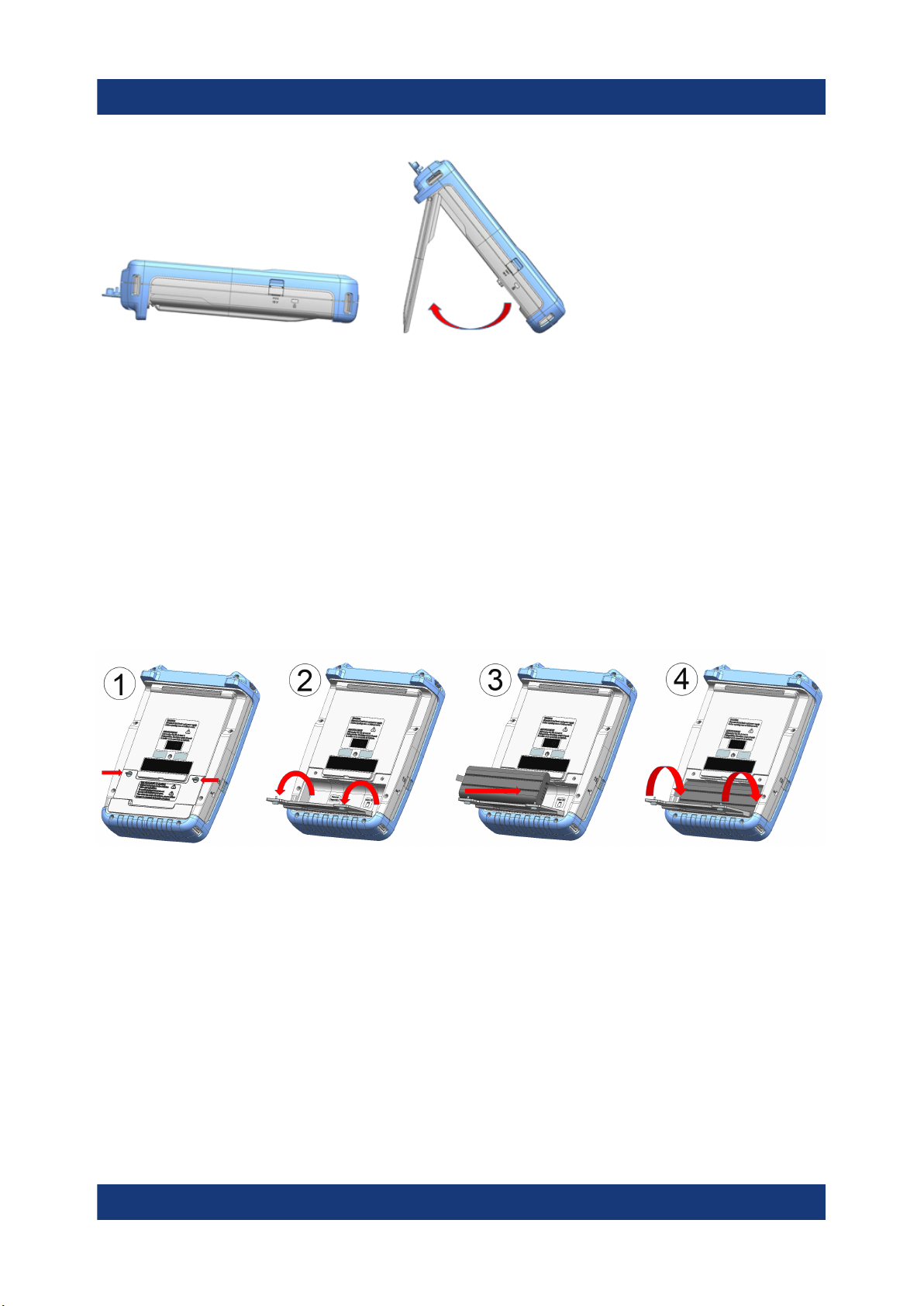
Depending on the environment, you can adjust the viewing angle of the display
and either lay it out horizontally or prop it up using the support on the back of the
R&S Spectrum Rider.
14Getting Started 1321.0996.02 ─ 12
R&S®Spectrum Rider FPH
When laid out horizontally for operation from above, the R&S Spectrum Rider is
tilted slightly due to the micro-stand at the back. This position provides the optimum viewing angle for the display.
To allow easy operation from the front and still be able to read the display, you
can swing out the support on the back of the R&S Spectrum Rider.
Before you turn on the R&S Spectrum Rider, you should insert the lithium ion battery included in the delivery into the battery compartment located at the back of
the R&S Spectrum Rider.
Preparing for use
Putting into operation
Insert battery
1. Unscrew the two thumb screws located on the battery compartment.
2. Open the cover.
3. Insert the battery into the R&S Spectrum Rider.
4. Close the cover and screw back the thumb screws.
You can operate the R&S Spectrum Rider with the AC adapter or the battery.
Both are included in the delivery.
15Getting Started 1321.0996.02 ─ 12

R&S®Spectrum Rider FPH
Preparing for use
Putting into operation
5.1.4 Using the AC adapter
Risk of instrument damage
To avoid instrument damage:
●
Only use the power supply (R&S HA-Z301, order number 1321.1386.02)
included in the delivery.
●
Make sure that the AC supply voltage is compatible to the voltage specified on the power supply unit.
●
Attach the appropriate adapter to the power supply.
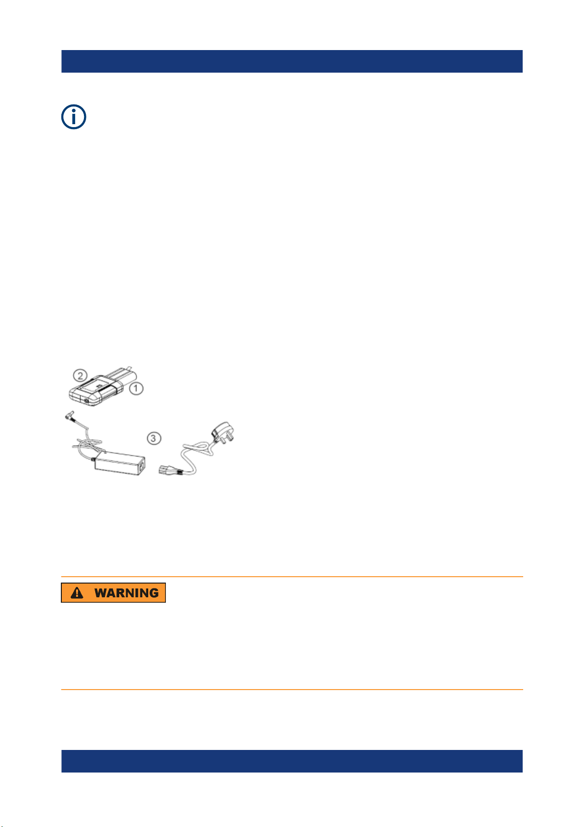
Connect the AC adapter to the DC port on the left side of the R&S Spectrum
Rider (item 1 of Figure 5-1). Make sure to fully insert the AC adapter plug into the
DC port.
Depending on the system you need, firmly connect the appropriate power cable
included in the delivery to the AC adapter (item 2 of Figure 5-1 ).
Finally, connect the power cable plug to an AC power outlet.
Figure 5-1: AC adapter
1 = AC adapter
2 = Power cable
The voltage range of the AC power supply is 100 V to 240 V AC.
After the R&S Spectrum Rider is connected to the power supply, you can turn it
on with the [Power] key on the front panel.
16Getting Started 1321.0996.02 ─ 12

R&S®Spectrum Rider FPH
Preparing for use
Putting into operation
5.1.5 Battery operation
The R&S Spectrum Rider has a smart battery indicator which displays the battery
charging status on the [Power] key as well as the battery icon shown at the top
right corner of the display screen. See Chapter 6.6.1, "Title bar", on page 32.
The lithium ion battery has a capacity of 6.4 Ah and it allows operation of up to
eight hours when it is fully charged.
The actual operation time depends on the current charged status (see Fig-
ure 5-2), the ambient temperature and the operating mode of the R&S Spectrum
Rider.
For a summary of the LED indication of the [Power] key, see Table 5-1.
The battery charging and discharging process of the battery icon indicated in the
display screen is illustrated below:
Figure 5-2: Battery charging and discharging process
Charging time is about three hours when the R&S Spectrum Rider is in inactive
mode (i.e. R&S Spectrum Rider is switched off). If the instrument is in active
mode (i.e. R&S Spectrum Rider is switched on), the charging time is extended to
about four hours because the charging current is reduced as the power is partially
drained by the usage of the R&S Spectrum Rider.
During operation in the field, you can also charge the battery with the car adapter
(R&S HA-Z302, order number 1321.1340.02). You can connect the car adapter to
the DC port. With the car adapter, you are able to charge the R&S Spectrum
Rider via the car's cigarette lighter socket. A replacement battery (R&S HA-Z306,
order number 1321.1334.02) with the same capacity and charging time as the
battery included in the standard delivery is also available if necessary.
17Getting Started 1321.0996.02 ─ 12
R&S®Spectrum Rider FPH
Preparing for use
Putting into operation
Battery dispatched during delivery is not fully charged, for battery operation
you have to charge it first.
To charge the battery, connect the charger to AC power adapter included in
the delivery. For more information, see "Using an external battery charger"
on page 18.
Using an external battery charger
You can also use an external battery charger (R&S HA-Z303, order number
1321.1328.02) to charge the battery.
To charge the battery externally, put the battery into the external charger and supply it with power via the AC power adapter.
An amber LED on the charger indicates the charging process. The LED turns to
green when the battery is fully charged. A red LED on the charger indicates that
the battery is not charging or the charging failed.
Figure 5-3: External battery charger
1 = Lithium ion battery R&S HA-Z306
2 = External charger R&S HA-Z303
3 = Power supply unit R&S HA-Z301 or car adapter R&S HA-Z302
Risk of traffic accidents, physical injury and property damage
●
Turn off the R&S Spectrum Rider while driving or while the engine is on.
●
Operation of the R&S Spectrum Rider via the cigarette lighter socket
while driving or while the engine on is prohibited.
18Getting Started 1321.0996.02 ─ 12

R&S®Spectrum Rider FPH
Preparing for use
Putting into operation
5.1.6 Battery maintenance
The R&S Spectrum Rider comes with a lithium-ion battery. In general, these batteries are easy to handle. When you handle the battery, follow the instruction
mentioned in the safety instructions and in the following chapters.
5.1.6.1 Handling
●
The battery has been designed for a specific application. Do not use it for any
other applications.
●
Do not connect batteries in series or parallel as it can cause serious damage.
●
Observe correct polarities during installation and charging.
●
Do not heat over 70°C. The battery contains thermal fuses that could activate
and render the battery inoperable.
●
The battery contains an electronic device for protection against deep discharge, overcharge and short-circuiting between the terminals.
– If you cannot discharge the battery, it may be deep discharged. Charge the
battery for 0.5 hours and check again.
– If you cannot charge the battery, it may be overcharged. Discharge the
battery and check again.
– If the battery has been short-circuited, charge it to reset the electronics.
– If the battery still does not work, contact the Rohde & Schwarz customer
support.
●
Do not allow metallic objects to come into contact with the terminals.
●
Do not solder directly to the battery.
5.1.6.2 Storage
The battery self-discharges while not in use. When storing the battery for an
extended period of time, make sure to
●
Handle the battery carefully to avoid short circuits. Make sure that leads and
terminals are insulated.
●
Keep the battery in the supplied packaging before use. The temperature
should be between -20°C to 50°C.
●
Store the battery at an initial state of charge between 15% and 50% of its
capacity. When calculating the initial state of charge, consider
19Getting Started 1321.0996.02 ─ 12

R&S®Spectrum Rider FPH
Switching the instrument on and off
– The maximum consumption of electronic devices
– The self-discharge of the battery - the higher the state of charge, the
higher the rate of self-discharge
●
Avoid a deep discharge of the battery. A deep discharge occurs when the
state of charge falls below 5% of the battery's capacity.
●
Recharge the battery at least every six months.
Should the battery voltage be low or even 0 V, the battery protection circuit may
have gone into a sleep mode. In that case, reset the battery with an approved
charger.
5.1.6.3 Transportation
No special regulations apply for transporting the battery. The battery cells contain
no metallic lithium.
Preparing for use
5.1.6.4 End of life
The capacity of the battery decreases after it has gone through numerous charge
cycles and nearing its end of life. When the battery is dead, do not open the battery. Do not dispose battery in fire.
5.2 Switching the instrument on and off
The instrument can be powered with an AC or DC (battery operated or via car
adapter) input. See Chapter 5.1.4, "Using the AC adapter", on page 16.
► Press [Power] key to switch on the instrument.
During booting, the R&S Spectrum Rider displays a splash screen to indicate
the operable frequency range of the instrument. Depending on the frequency
upgrade option installed, the respective splash screen is loaded.
After booting, the instrument is ready for operation.
Refer to the instrument brochure for the list of options available.
► Press [Power] key to switch off the instrument.
20Getting Started 1321.0996.02 ─ 12

R&S®Spectrum Rider FPH
Preparing for use
Checking the supplied options
Risk of losing data
If a running instrument (without battery) is disconnected directly from the
power cord, the instrument loses its current settings. Furthermore, program
data may be lost.
Press [Power] key first to shut down the application properly.
The following shows the [POWER] key behavior in different operation modes.
Table 5-1: Summary of LED indication on POWER key
LED indication on [Power]
key
Green LED Instrument is in operation mode.
Blue LED Instrument is in switch off mode with a fully charged battery.
Amber LED Instrument is in switch off mode with AC supply and there is
Red LED There is an error in the battery charging.
LED "OFF" This is an indication that there is no AC or DC supply to the
Descriptions
A blinking blue LED indicates that the battery charging is in
process.
no battery in it.
instrument. The instrument is in a switch off mode.
5.3 Checking the supplied options
The instrument can be equipped with different hardware and installed options. For
a list of R&S Spectrum Rider supported hardware and installed options, refer to
the instrument brochure for the list of options available.
In order to check whether the installed options correspond to the options indicated in the delivery note, proceed as follows.
1. Press [SETUP] key.
2. Select "Installed Options" softkey.
A list of all available options and the current status of the options are displayed.
21Getting Started 1321.0996.02 ─ 12

R&S®Spectrum Rider FPH
Preparing for use
Checking the supplied options
3. Check the availability of the installed options as indicated in the delivery note.
4. Check the availability of the hardware options as indicated in the delivery
note.
5. Press "HW/SW Info" softkey.
A list with hardware and firmware information is displayed.
22Getting Started 1321.0996.02 ─ 12

R&S®Spectrum Rider FPH
Preparing for use
Checking the supplied options
23Getting Started 1321.0996.02 ─ 12

R&S®Spectrum Rider FPH
Instrument tour
6 Instrument tour
This chapter describes the instrument in different views, including all function
keys and connectors.
It also contains general system configuration on the R&S Spectrum Rider as well
as the connectivity of the instrument to PC.
● Front view........................................................................................................25
● Top view.......................................................................................................... 26
● Left view..........................................................................................................29
● Right view........................................................................................................29
● Rear view........................................................................................................ 30
● Touchscreen display........................................................................................30
● On-screen keyboard........................................................................................39
● Front panel keys..............................................................................................39
● Managing options............................................................................................44
● Configuring the R&S Spectrum Rider............................................................. 47
● Connecting the R&S Spectrum Rider to a PC.................................................68
24Getting Started 1321.0996.02 ─ 12

R&S®Spectrum Rider FPH
6.1 Front view
Instrument tour
Front view
Figure 6-1: Front panel of R&S Spectrum Rider
1 = RF input (N-type, PC 3.5 mm or PC 2.92 mm connector)
2 = BNC connectors
3 = Headphone jack
4 = USB ports
5 = RF output (N-type, PC 3.5 mm or PC 2.92 mm connector)
6 = Touch-sensitive screen area
7 = Softkey labels (on display)
8 = Softkey
9 = System keys
10 = DC port (behind protective cap)
11 = Kensington lock
12 = Function keys
13 = Power key
14 = Alphanumeric key
15 = Unit keys
16 = Back key
17 = Cancel key
18 = Rotary knob
19 = Screenshot key
20 = LAN and mini USB ports (behind protective cap)
**21 = SD card slot (not visible as it is located behind the battery compartment)
For a detailed description of the front panel keys, see "Front Panel Keys" in the
R&S Spectrum Rider user manual.
25Getting Started 1321.0996.02 ─ 12

R&S®Spectrum Rider FPH
Instrument damage caused by cleaning agents
Cleaning agents contain substances that may damage the instrument. For
example, cleaning agents that contain a solvent may damage the front
panel labeling, plastic parts, or the display.
Never use cleaning agents such as solvents (thinners, acetone, etc.), acids,
bases, or other substances.
The outside of the instrument can be cleaned sufficiently using a soft, lintfree dust cloth.
6.2 Top view
Instrument tour
Top view
1 = RF input
2 = BNC connector
3 = Headphone jack
4 = USB type A connector
5 = RF output
RF input
Depending on the instrument models, different RF connector is used.
Table 6-1: Types of RF connectors
Instrument models Type of RF connector, 50 Ω
Model 02, model 06, model 13 and model 23 N type
Model 26 and model 36 RPC 3.5 mm
Model 44 and model 54 RPC 2.9 mm
Connect a cable or DUT to the RF input. Use a cable to connect the DUT to the
R&S Spectrum Rider, if necessary.
26Getting Started 1321.0996.02 ─ 12

R&S®Spectrum Rider FPH
Make sure not to overload the R&S Spectrum Rider when a DUT is connected.
The maximum power that is permissible at the RF input is 20 dBm (or 100 mW).
The RF input is protected from static discharges and voltage pulses by a limiting
circuit.
RF power overload
The R&S Spectrum Rider maybe loaded with up to 30 dBm (or 1 W ) for up
to three minutes. If you apply 1 W for a longer period, the R&S Spectrum
Rider may be destroyed.
Instrument tour
Top view
Risk of electric shock
To avoid electrical shock the DC input voltage, you must never exceed the
value specified on the housing.
Risk of damage of the R&S Spectrum Rider
To avoid damage to the coupling capacitor, input attenuator or the mixer,
the DC input voltage must never exceed the value specified in the data
sheet.
BNC connector
You can connect the BNC connector for various applications. It supports an external trigger signal or an external reference signal.
When the BNC connector is configured as a trigger input, it controls the start of a
measurement. The trigger mode is selected in the "Sweep" menu, see Chap-
ter 6.8.5, "Function keys", on page 41. The trigger threshold is similar to that of
TTL signals.
When the BNC connector is configured as reference input, you can apply a 10
MHz external reference signal to it for frequency synchronization. The external
reference label is displayed at the top right corner of the trace window to indi-
27Getting Started 1321.0996.02 ─ 12

R&S®Spectrum Rider FPH
cate that the reference signal is supplied via external signal input. The label turns
green when the reference signal is detected.
The level of the reference signal must be larger than 0 dBm. If there is no reference signal present at the BNC connector, the R&S Spectrum Rider displays an
appropriate message. Thus, measurements without a valid reference can be avoided.
For more information on configuring the BNC connector for the appropriate signal,
see "Configuring the BNC connector" on page 49 and Chapter 6.10.3, "Using
the GPS receiver", on page 54.
Headphone jack
The 3.5 mm connector for headphones has an internal impedance of approximately 10 Ω.
USB type A connector
Instrument tour
Top view
There are two USB ports located on top of the R&S Spectrum Rider.
You can use the USB interface to connect a memory stick and store data sets or
screenshots. The USB connector can also be used to control the operation of the
external power sensor and GPS receiver.
See Chapter 7.2, "Using a power sensor", on page 84 and Chapter 6.10.3,
"Using the GPS receiver", on page 54.
RF output
Applicable for model 23, model 36 and model 54, the RF output connector provides the following ways to generate a signal source output power at -10.00 dBm
nominal.
●
Tracking generator output
●
Continuous signal source output
●
Coupled continuous signal source output
For types of RF output connectors, see Table 6-1.
For more information on configuring the RF output for signal source, see "Configuring the Tracking Generator" chapter in the R&S Spectrum Rider user manual.
28Getting Started 1321.0996.02 ─ 12
R&S®Spectrum Rider FPH
Instrument tour
Right view
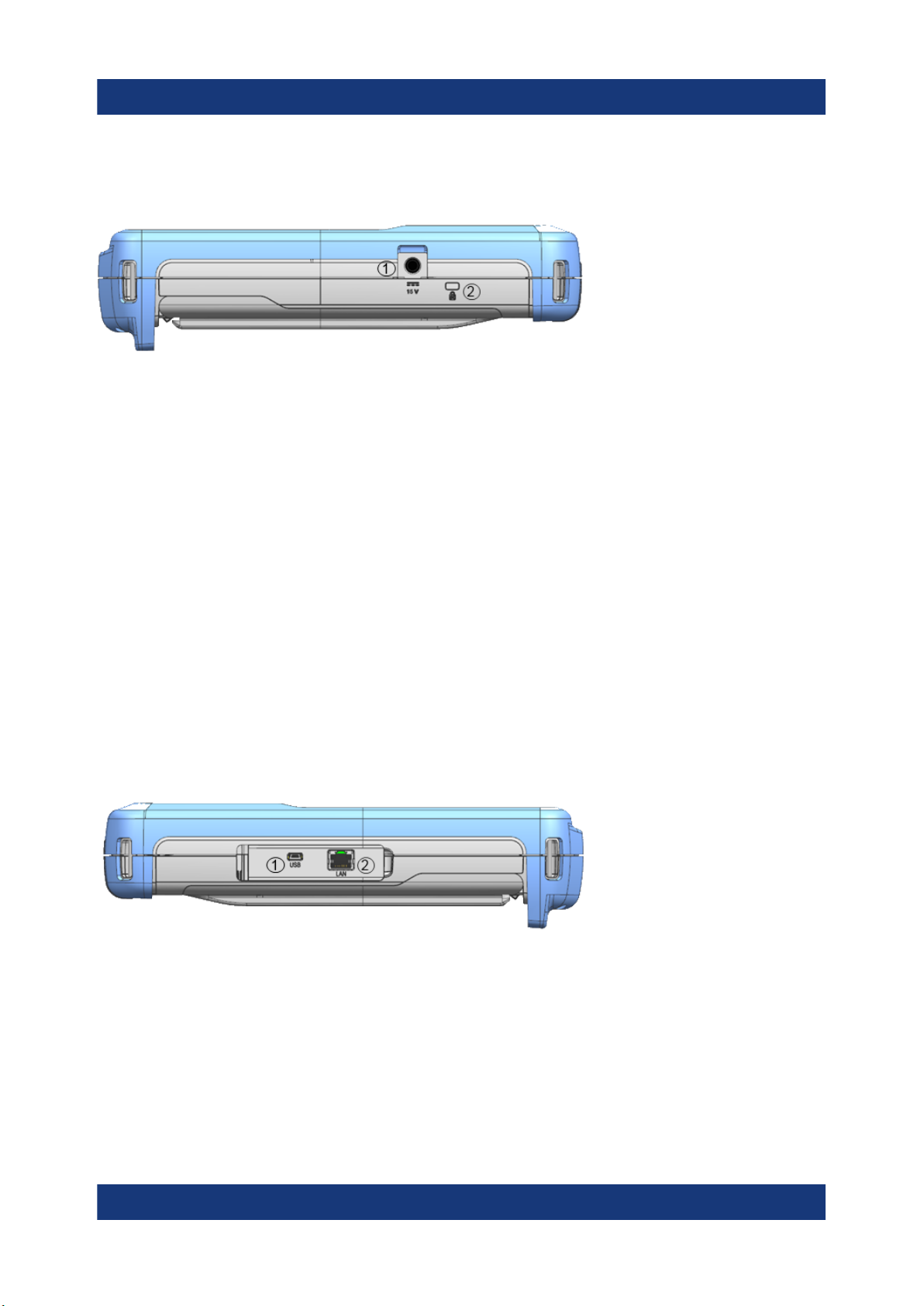
6.3 Left view
1 = DC port
2 = Kensington lock slot
DC port
The R&S Spectrum Rider is supplied with power by the AC/DC transformer power
supply via the DC connector. You can also use the DC connector to charge the
battery.
Kensington lock slot
A Kensington lock can be anchored to the R&S Spectrum Rider housing to
secure it to a workstation mechanically.
6.4 Right view
1 = Mini USB
2 = LAN port
Mini USB
Mini USB connector to connect a computer for remote control of the instrument
and transfer data in both directions.
29Getting Started 1321.0996.02 ─ 12
 Loading...