

Page 1
R&S®EX-IQ-BOX
Digital Interface Module
R&S®DigIConf Software
User Manual
(>9ÅÔP)
1409.5570.32 ─ 06
User Manual
Test & Measurement
Page 2

This document describes the R&S®EX-IQ-BOX models:
●
R&S®EX-IQ-BOX 1409.5505K04 and its options,
●
R&S®EX-IQ-BOX 1409.5505.02,
and the R&S®DigIConf (Digital Interface Configurator) software.
The firmware of the instrument makes use of several valuable open source software packages. For information, see the "Open Source
Acknowledgement" on the user documentation CD-ROM (included in delivery).
Rohde & Schwarz would like to thank the open source community for their valuable contribution to embedded computing.
© 2017 Rohde & Schwarz GmbH & Co. KG
Mhldorfstr. 15, 81671 Mnchen, Germany
Phone: +49 89 41 29 - 0
Fax: +49 89 41 29 12 164
E-mail: info@rohde-schwarz.com
Internet: www.rohde-schwarz.com
Subject to change – Data without tolerance limits is not binding.
R&S® is a registered trademark of Rohde & Schwarz GmbH & Co. KG.
Trade names are trademarks of the owners.
Throughout this manual R&S® is abbreviated as R&S and applies to the following R&S products: R&S®EX-IQ-BOX , R&S®DigIConf,
R&S®AMU200A, R&S®SMU200A, R&S®SMBV100A, R&S®SMJ100A, R&S®FSQ, R&S®FSW, R&S®FSG, R&S®FMU36, R&S®FSV,
R&S®CMW500 and R&S®WinIQSIM2.
Page 3
Basic Safety Instructions
Symbol
Meaning
Symbol
Meaning
Notice, general danger location
Observe product documentation
ON/OFF Power
Caution when handling heavy equipment
Standby indication
Danger of electric shock
Direct current (DC)
Always read through and comply with the following safety instructions!
All plants and locations of the Rohde & Schwarz group of companies make every effort to keep the safety
standards of our products up to date and to offer our customers the highest possible degree of safety. Our
products and the auxiliary equipment they require are designed, built and tested in accordance with the
safety standards that apply in each case. Compliance with these standards is continuously monitored by
our quality assurance system. The product described here has been designed, built and tested in
accordance with the EC Certificate of Conformity and has left the manufacturer’s plant in a condition fully
complying with safety standards. To maintain this condition and to ensure safe operation, you must
observe all instructions and warnings provided in this manual. If you have any questions regarding these
safety instructions, the Rohde & Schwarz group of companies will be happy to answer them.
Furthermore, it is your responsibility to use the product in an appropriate manner. This product is designed
for use solely in industrial and laboratory environments or, if expressly permitted, also in the field and must
not be used in any way that may cause personal injury or property damage. You are responsible if the
product is used for any purpose other than its designated purpose or in disregard of the manufacturer's
instructions. The manufacturer shall assume no responsibility for such use of the product.
The product is used for its designated purpose if it is used in accordance with its product documentation
and within its performance limits (see data sheet, documentation, the following safety instructions). Using
the product requires technical skills and, in some cases, a basic knowledge of English. It is therefore
essential that only skilled and specialized staff or thoroughly trained personnel with the required skills be
allowed to use the product. If personal safety gear is required for using Rohde & Schwarz products, this
will be indicated at the appropriate place in the product documentation. Keep the basic safety instructions
and the product documentation in a safe place and pass them on to the subsequent users.
Observing the safety instructions will help prevent personal injury or damage of any kind caused by
dangerous situations. Therefore, carefully read through and adhere to the following safety instructions
before and when using the product. It is also absolutely essential to observe the additional safety
instructions on personal safety, for example, that appear in relevant parts of the product documentation. In
these safety instructions, the word "product" refers to all merchandise sold and distributed by the Rohde &
Schwarz group of companies, including instruments, systems and all accessories. For product-specific
information, see the data sheet and the product documentation.
Safety labels on products
The following safety labels are used on products to warn against risks and dangers.
1171.0000.42 - 09 Page 1
Page 4
Basic Safety Instructions
Symbol
Meaning
Symbol
Meaning
Caution ! Hot surface
Alternating current (AC)
Protective conductor terminal
To identify any terminal which is intended for
connection to an external conductor for
protection against electric shock in case of a
fault, or the terminal of a protective earth
Direct/alternating current (DC/AC)
Earth (Ground)
Class II Equipment
to identify equipment meeting the safety
requirements specified for Class II equipment
(device protected by double or reinforced
insulation)
Frame or chassis Ground terminal
EU labeling for batteries and accumulators
For additional information, see section "Waste
disposal/Environmental protection", item 1.
Be careful when handling electrostatic sensitive
devices
EU labeling for separate collection of electrical
and electronic devices
For additional information, see section "Waste
disposal/Environmental protection", item 2.
Warning! Laser radiation
For additional information, see section
"Operation", item 7.
Indicates a hazardous situation which, if not avoided, will result in death or
serious injury.
Indicates a hazardous situation which, if not avoided, could result in death or
serious injury.
Indicates a hazardous situation which, if not avoided, could result in minor or
moderate injury.
Indicates information considered important, but not hazard-related, e.g.
messages relating to property damage.
In the product documentation, the word ATTENTION is used synonymously.
Signal words and their meaning
The following signal words are used in the product documentation in order to warn the reader about risks
and dangers.
These signal words are in accordance with the standard definition for civil applications in the European
Economic Area. Definitions that deviate from the standard definition may also exist in other economic
areas or military applications. It is therefore essential to make sure that the signal words described here
are always used only in connection with the related product documentation and the related product. The
use of signal words in connection with unrelated products or documentation can result in misinterpretation
and in personal injury or material damage.
1171.0000.42 - 09 Page 2
Page 5

Basic Safety Instructions
Operating states and operating positions
The product may be operated only under the operating conditions and in the positions specified by the
manufacturer, without the product's ventilation being obstructed. If the manufacturer's specifications are
not observed, this can result in electric shock, fire and/or serious personal injury or death. Applicable local
or national safety regulations and rules for the prevention of accidents must be observed in all work
performed.
1. Unless otherwise specified, the following requirements apply to Rohde & Schwarz products:
predefined operating position is always with the housing floor facing down, IP protection 2X, use only
indoors, max. operating altitude 2000 m above sea level, max. transport altitude 4500 m above sea
level. A tolerance of ±10 % shall apply to the nominal voltage and ±5 % to the nominal frequency,
overvoltage category 2, pollution degree 2.
2. Do not place the product on surfaces, vehicles, cabinets or tables that for reasons of weight or stability
are unsuitable for this purpose. Always follow the manufacturer's installation instructions when
installing the product and fastening it to objects or structures (e.g. walls and shelves). An installation
that is not carried out as described in the product documentation could result in personal injury or
even death.
3. Do not place the product on heat-generating devices such as radiators or fan heaters. The ambient
temperature must not exceed the maximum temperature specified in the product documentation or in
the data sheet. Product overheating can cause electric shock, fire and/or serious personal injury or
even death.
Electrical safety
If the information on electrical safety is not observed either at all or to the extent necessary, electric shock,
fire and/or serious personal injury or death may occur.
1. Prior to switching on the product, always ensure that the nominal voltage setting on the product
matches the nominal voltage of the mains-supply network. If a different voltage is to be set, the power
fuse of the product may have to be changed accordingly.
2. In the case of products of safety class I with movable power cord and connector, operation is
permitted only on sockets with a protective conductor contact and protective conductor.
3. Intentionally breaking the protective conductor either in the feed line or in the product itself is not
permitted. Doing so can result in the danger of an electric shock from the product. If extension cords
or connector strips are implemented, they must be checked on a regular basis to ensure that they are
safe to use.
4. If there is no power switch for disconnecting the product from the mains, or if the power switch is not
suitable for this purpose, use the plug of the connecting cable to disconnect the product from the
mains. In such cases, always ensure that the power plug is easily reachable and accessible at all
times. For example, if the power plug is the disconnecting device, the length of the connecting cable
must not exceed 3 m. Functional or electronic switches are not suitable for providing disconnection
from the AC supply network. If products without power switches are integrated into racks or systems,
the disconnecting device must be provided at the system level.
5. Never use the product if the power cable is damaged. Check the power cables on a regular basis to
ensure that they are in proper operating condition. By taking appropriate safety measures and
carefully laying the power cable, ensure that the cable cannot be damaged and that no one can be
hurt by, for example, tripping over the cable or suffering an electric shock.
1171.0000.42 - 09 Page 3
Page 6

Basic Safety Instructions
6. The product may be operated only from TN/TT supply networks fuse-protected with max. 16 A (higher
fuse only after consulting with the Rohde & Schwarz group of companies).
7. Do not insert the plug into sockets that are dusty or dirty. Insert the plug firmly and all the way into the
socket provided for this purpose. Otherwise, sparks that result in fire and/or injuries may occur.
8. Do not overload any sockets, extension cords or connector strips; doing so can cause fire or electric
shocks.
9. For measurements in circuits with voltages V
> 30 V, suitable measures (e.g. appropriate
rms
measuring equipment, fuse protection, current limiting, electrical separation, insulation) should be
taken to avoid any hazards.
10. Ensure that the connections with information technology equipment, e.g. PCs or other industrial
computers, comply with the IEC 60950-1 / EN 60950-1 or IEC 61010-1 / EN 61010-1 standards that
apply in each case.
11. Unless expressly permitted, never remove the cover or any part of the housing while the product is in
operation. Doing so will expose circuits and components and can lead to injuries, fire or damage to the
product.
12. If a product is to be permanently installed, the connection between the protective conductor terminal
on site and the product's protective conductor must be made first before any other connection is
made. The product may be installed and connected only by a licensed electrician.
13. For permanently installed equipment without built-in fuses, circuit breakers or similar protective
devices, the supply circuit must be fuse-protected in such a way that anyone who has access to the
product, as well as the product itself, is adequately protected from injury or damage.
14. Use suitable overvoltage protection to ensure that no overvoltage (such as that caused by a bolt of
lightning) can reach the product. Otherwise, the person operating the product will be exposed to the
danger of an electric shock.
15. Any object that is not designed to be placed in the openings of the housing must not be used for this
purpose. Doing so can cause short circuits inside the product and/or electric shocks, fire or injuries.
16. Unless specified otherwise, products are not liquid-proof (see also section "Operating states and
operating positions", item 1). Therefore, the equipment must be protected against penetration by
liquids. If the necessary precautions are not taken, the user may suffer electric shock or the product
itself may be damaged, which can also lead to personal injury.
17. Never use the product under conditions in which condensation has formed or can form in or on the
product, e.g. if the product has been moved from a cold to a warm environment. Penetration by water
increases the risk of electric shock.
18. Prior to cleaning the product, disconnect it completely from the power supply (e.g. AC supply network
or battery). Use a soft, non-linting cloth to clean the product. Never use chemical cleaning agents such
as alcohol, acetone or diluents for cellulose lacquers.
Operation
1. Operating the products requires special training and intense concentration. Make sure that persons
who use the products are physically, mentally and emotionally fit enough to do so; otherwise, injuries
or material damage may occur. It is the responsibility of the employer/operator to select suitable
personnel for operating the products.
1171.0000.42 - 09 Page 4
Page 7

Basic Safety Instructions
2. Before you move or transport the product, read and observe the section titled "Transport".
3. As with all industrially manufactured goods, the use of substances that induce an allergic reaction
(allergens) such as nickel cannot be generally excluded. If you develop an allergic reaction (such as a
skin rash, frequent sneezing, red eyes or respiratory difficulties) when using a Rohde & Schwarz
product, consult a physician immediately to determine the cause and to prevent health problems or
stress.
4. Before you start processing the product mechanically and/or thermally, or before you take it apart, be
sure to read and pay special attention to the section titled "Waste disposal/Environmental protection",
item 1.
5. Depending on the function, certain products such as RF radio equipment can produce an elevated
level of electromagnetic radiation. Considering that unborn babies require increased protection,
pregnant women must be protected by appropriate measures. Persons with pacemakers may also be
exposed to risks from electromagnetic radiation. The employer/operator must evaluate workplaces
where there is a special risk of exposure to radiation and, if necessary, take measures to avert the
potential danger.
6. Should a fire occur, the product may release hazardous substances (gases, fluids, etc.) that can
cause health problems. Therefore, suitable measures must be taken, e.g. protective masks and
protective clothing must be worn.
7. Laser products are given warning labels that are standardized according to their laser class. Lasers
can cause biological harm due to the properties of their radiation and due to their extremely
concentrated electromagnetic power. If a laser product (e.g. a CD/DVD drive) is integrated into a
Rohde & Schwarz product, absolutely no other settings or functions may be used as described in the
product documentation. The objective is to prevent personal injury (e.g. due to laser beams).
8. EMC classes (in line with EN 55011/CISPR 11, and analogously with EN 55022/CISPR 22,
EN 55032/CISPR 32)
Class A equipment:
Equipment suitable for use in all environments except residential environments and environments
that are directly connected to a low-voltage supply network that supplies residential buildings
Note: Class A equipment is intended for use in an industrial environment. This equipment may
cause radio disturbances in residential environments, due to possible conducted as well as
radiated disturbances. In this case, the operator may be required to take appropriate measures to
eliminate these disturbances.
Class B equipment:
Equipment suitable for use in residential environments and environments that are directly
connected to a low-voltage supply network that supplies residential buildings
Repair and service
1. The product may be opened only by authorized, specially trained personnel. Before any work is
performed on the product or before the product is opened, it must be disconnected from the AC supply
network. Otherwise, personnel will be exposed to the risk of an electric shock.
1171.0000.42 - 09 Page 5
Page 8

Basic Safety Instructions
2. Adjustments, replacement of parts, maintenance and repair may be performed only by electrical
experts authorized by Rohde & Schwarz. Only original parts may be used for replacing parts relevant
to safety (e.g. power switches, power transformers, fuses). A safety test must always be performed
after parts relevant to safety have been replaced (visual inspection, protective conductor test,
insulation resistance measurement, leakage current measurement, functional test). This helps ensure
the continued safety of the product.
Batteries and rechargeable batteries/cells
If the information regarding batteries and rechargeable batteries/cells is not observed either at all or to the
extent necessary, product users may be exposed to the risk of explosions, fire and/or serious personal
injury, and, in some cases, death. Batteries and rechargeable batteries with alkaline electrolytes (e.g.
lithium cells) must be handled in accordance with the EN 62133 standard.
1. Cells must not be taken apart or crushed.
2. Cells or batteries must not be exposed to heat or fire. Storage in direct sunlight must be avoided.
Keep cells and batteries clean and dry. Clean soiled connectors using a dry, clean cloth.
3. Cells or batteries must not be short-circuited. Cells or batteries must not be stored in a box or in a
drawer where they can short-circuit each other, or where they can be short-circuited by other
conductive materials. Cells and batteries must not be removed from their original packaging until they
are ready to be used.
4. Cells and batteries must not be exposed to any mechanical shocks that are stronger than permitted.
5. If a cell develops a leak, the fluid must not be allowed to come into contact with the skin or eyes. If
contact occurs, wash the affected area with plenty of water and seek medical aid.
6. Improperly replacing or charging cells or batteries that contain alkaline electrolytes (e.g. lithium cells)
can cause explosions. Replace cells or batteries only with the matching Rohde & Schwarz type (see
parts list) in order to ensure the safety of the product.
7. Cells and batteries must be recycled and kept separate from residual waste. Rechargeable batteries
and normal batteries that contain lead, mercury or cadmium are hazardous waste. Observe the
national regulations regarding waste disposal and recycling.
8. Follow the transport stipulations of the carrier (IATA-DGR, IMDG-Code, ADR, RID) when returning
lithium batteries to Rohde & Schwarz subsidiaries.
Transport
1. The product may be very heavy. Therefore, the product must be handled with care. In some cases,
the user may require a suitable means of lifting or moving the product (e.g. with a lift-truck) to avoid
back or other physical injuries.
2. Handles on the products are designed exclusively to enable personnel to transport the product. It is
therefore not permissible to use handles to fasten the product to or on transport equipment such as
cranes, fork lifts, wagons, etc. The user is responsible for securely fastening the products to or on the
means of transport or lifting. Observe the safety regulations of the manufacturer of the means of
transport or lifting. Noncompliance can result in personal injury or material damage.
1171.0000.42 - 09 Page 6
Page 9

Instrucciones de seguridad elementales
3. If you use the product in a vehicle, it is the sole responsibility of the driver to drive the vehicle safely
and properly. The manufacturer assumes no responsibility for accidents or collisions. Never use the
product in a moving vehicle if doing so could distract the driver of the vehicle. Adequately secure the
product in the vehicle to prevent injuries or other damage in the event of an accident.
Waste disposal/Environmental protection
1. Specially marked equipment has a battery or accumulator that must not be disposed of with unsorted
municipal waste, but must be collected separately. It may only be disposed of at a suitable collection
point or via a Rohde & Schwarz customer service center.
2. Waste electrical and electronic equipment must not be disposed of with unsorted municipal waste, but
must be collected separately.
Rohde & Schwarz GmbH & Co. KG has developed a disposal concept and takes full responsibility for
take-back obligations and disposal obligations for manufacturers within the EU. Contact your
Rohde & Schwarz customer service center for environmentally responsible disposal of the product.
3. If products or their components are mechanically and/or thermally processed in a manner that goes
beyond their intended use, hazardous substances (heavy-metal dust such as lead, beryllium, nickel)
may be released. For this reason, the product may only be disassembled by specially trained
personnel. Improper disassembly may be hazardous to your health. National waste disposal
regulations must be observed.
4. If handling the product releases hazardous substances or fuels that must be disposed of in a special
way, e.g. coolants or engine oils that must be replenished regularly, the safety instructions of the
manufacturer of the hazardous substances or fuels and the applicable regional waste disposal
regulations must be observed. Also observe the relevant safety instructions in the product
documentation. The improper disposal of hazardous substances or fuels can cause health problems
and lead to environmental damage.
For additional information about environmental protection, visit the Rohde & Schwarz website.
Instrucciones de seguridad elementales
¡Es imprescindible leer y cumplir las siguientes instrucciones e informaciones de seguridad!
El principio del grupo de empresas Rohde & Schwarz consiste en tener nuestros productos siempre al día
con los estándares de seguridad y de ofrecer a nuestros clientes el máximo grado de seguridad. Nuestros
productos y todos los equipos adicionales son siempre fabricados y examinados según las normas de
seguridad vigentes. Nuestro sistema de garantía de calidad controla constantemente que sean cumplidas
estas normas. El presente producto ha sido fabricado y examinado según el certificado de conformidad
de la UE y ha salido de nuestra planta en estado impecable según los estándares técnicos de seguridad.
Para poder preservar este estado y garantizar un funcionamiento libre de peligros, el usuario deberá
atenerse a todas las indicaciones, informaciones de seguridad y notas de alerta. El grupo de empresas
Rohde & Schwarz está siempre a su disposición en caso de que tengan preguntas referentes a estas
informaciones de seguridad.
1171.0000.42 - 09 Page 7
Page 10
Instrucciones de seguridad elementales
Símbolo
Significado
Símbolo
Significado
Aviso: punto de peligro general
Observar la documentación del producto
Tensión de alimentación de PUESTA EN
MARCHA / PARADA
Atención en el manejo de dispositivos de peso
elevado
Indicación de estado de espera (standby)
Peligro de choque eléctrico
Corriente continua (DC)
Advertencia: superficie caliente
Corriente alterna (AC)
Conexión a conductor de protección
Corriente continua / Corriente alterna (DC/AC)
Además queda en la responsabilidad del usuario utilizar el producto en la forma debida. Este producto
está destinado exclusivamente al uso en la industria y el laboratorio o, si ha sido expresamente
autorizado, para aplicaciones de campo y de ninguna manera deberá ser utilizado de modo que alguna
persona/cosa pueda sufrir daño. El uso del producto fuera de sus fines definidos o sin tener en cuenta las
instrucciones del fabricante queda en la responsabilidad del usuario. El fabricante no se hace en ninguna
forma responsable de consecuencias a causa del mal uso del producto.
Se parte del uso correcto del producto para los fines definidos si el producto es utilizado conforme a las
indicaciones de la correspondiente documentación del producto y dentro del margen de rendimiento
definido (ver hoja de datos, documentación, informaciones de seguridad que siguen). El uso del producto
hace necesarios conocimientos técnicos y ciertos conocimientos del idioma inglés. Por eso se debe tener
en cuenta que el producto solo pueda ser operado por personal especializado o personas instruidas en
profundidad con las capacidades correspondientes. Si fuera necesaria indumentaria de seguridad para el
uso de productos de Rohde & Schwarz, encontraría la información debida en la documentación del
producto en el capítulo correspondiente. Guarde bien las informaciones de seguridad elementales, así
como la documentación del producto, y entréguelas a usuarios posteriores.
Tener en cuenta las informaciones de seguridad sirve para evitar en lo posible lesiones o daños por
peligros de toda clase. Por eso es imprescindible leer detalladamente y comprender por completo las
siguientes informaciones de seguridad antes de usar el producto, y respetarlas durante el uso del
producto. Deberán tenerse en cuenta todas las demás informaciones de seguridad, como p. ej. las
referentes a la protección de personas, que encontrarán en el capítulo correspondiente de la
documentación del producto y que también son de obligado cumplimiento. En las presentes
informaciones de seguridad se recogen todos los objetos que distribuye el grupo de empresas
Rohde & Schwarz bajo la denominación de "producto", entre ellos también aparatos, instalaciones así
como toda clase de accesorios. Los datos específicos del producto figuran en la hoja de datos y en la
documentación del producto.
Señalización de seguridad de los productos
Las siguientes señales de seguridad se utilizan en los productos para advertir sobre riesgos y peligros.
1171.0000.42 - 09 Page 8
Page 11
Instrucciones de seguridad elementales
Símbolo
Significado
Símbolo
Significado
Conexión a tierra
El aparato está protegido en su totalidad por un
aislamiento doble (reforzado)
Conexión a masa
Distintivo de la UE para baterías y
acumuladores
Más información en la sección
"Eliminación/protección del medio ambiente",
punto 1.
Aviso: Cuidado en el manejo de dispositivos
sensibles a la electrostática (ESD)
Distintivo de la UE para la eliminación por
separado de dispositivos eléctricos y
electrónicos
Más información en la sección
"Eliminación/protección del medio ambiente",
punto 2.
Advertencia: rayo láser
Más información en la sección
"Funcionamiento", punto 7.
Indica una situación de peligro que, si no se evita, causa lesiones
graves o incluso la muerte.
Indica una situación de peligro que, si no se evita, puede causar
lesiones graves o incluso la muerte.
Indica una situación de peligro que, si no se evita, puede causar
lesiones leves o moderadas.
Indica información que se considera importante, pero no en relación
con situaciones de peligro; p. ej., avisos sobre posibles daños
materiales.
En la documentación del producto se emplea de forma sinónima el
término CUIDADO.
Palabras de señal y su significado
En la documentación del producto se utilizan las siguientes palabras de señal con el fin de advertir contra
riesgos y peligros.
Las palabras de señal corresponden a la definición habitual para aplicaciones civiles en el área
económica europea. Pueden existir definiciones diferentes a esta definición en otras áreas económicas o
en aplicaciones militares. Por eso se deberá tener en cuenta que las palabras de señal aquí descritas
sean utilizadas siempre solamente en combinación con la correspondiente documentación del producto y
solamente en combinación con el producto correspondiente. La utilización de las palabras de señal en
combinación con productos o documentaciones que no les correspondan puede llevar a interpretaciones
equivocadas y tener por consecuencia daños en personas u objetos.
1171.0000.42 - 09 Page 9
Page 12

Instrucciones de seguridad elementales
Estados operativos y posiciones de funcionamiento
El producto solamente debe ser utilizado según lo indicado por el fabricante respecto a los estados
operativos y posiciones de funcionamiento sin que se obstruya la ventilación. Si no se siguen las
indicaciones del fabricante, pueden producirse choques eléctricos, incendios y/o lesiones graves con
posible consecuencia de muerte. En todos los trabajos deberán ser tenidas en cuenta las normas
nacionales y locales de seguridad del trabajo y de prevención de accidentes.
1. Si no se convino de otra manera, es para los productos Rohde & Schwarz válido lo que sigue:
como posición de funcionamiento se define por principio la posición con el suelo de la caja para
abajo, modo de protección IP 2X, uso solamente en estancias interiores, utilización hasta 2000 m
sobre el nivel del mar, transporte hasta 4500 m sobre el nivel del mar. Se aplicará una tolerancia de
±10 % sobre el voltaje nominal y de ±5 % sobre la frecuencia nominal. Categoría de sobrecarga
eléctrica 2, índice de suciedad 2.
2. No sitúe el producto encima de superficies, vehículos, estantes o mesas, que por sus características
de peso o de estabilidad no sean aptos para él. Siga siempre las instrucciones de instalación del
fabricante cuando instale y asegure el producto en objetos o estructuras (p. ej. paredes y estantes). Si
se realiza la instalación de modo distinto al indicado en la documentación del producto, se pueden
causar lesiones o, en determinadas circunstancias, incluso la muerte.
3. No ponga el producto sobre aparatos que generen calor (p. ej. radiadores o calefactores). La
temperatura ambiente no debe superar la temperatura máxima especificada en la documentación del
producto o en la hoja de datos. En caso de sobrecalentamiento del producto, pueden producirse
choques eléctricos, incendios y/o lesiones graves con posible consecuencia de muerte.
Seguridad eléctrica
Si no se siguen (o se siguen de modo insuficiente) las indicaciones del fabricante en cuanto a seguridad
eléctrica, pueden producirse choques eléctricos, incendios y/o lesiones graves con posible consecuencia
de muerte.
1. Antes de la puesta en marcha del producto se deberá comprobar siempre que la tensión
preseleccionada en el producto coincida con la de la red de alimentación eléctrica. Si es necesario
modificar el ajuste de tensión, también se deberán cambiar en caso dado los fusibles
correspondientes del producto.
2. Los productos de la clase de protección I con alimentación móvil y enchufe individual solamente
podrán enchufarse a tomas de corriente con contacto de seguridad y con conductor de protección
conectado.
3. Queda prohibida la interrupción intencionada del conductor de protección, tanto en la toma de
corriente como en el mismo producto. La interrupción puede tener como consecuencia el riesgo de
que el producto sea fuente de choques eléctricos. Si se utilizan cables alargadores o regletas de
enchufe, deberá garantizarse la realización de un examen regular de los mismos en cuanto a su
estado técnico de seguridad.
4. Si el producto no está equipado con un interruptor para desconectarlo de la red, o bien si el
interruptor existente no resulta apropiado para la desconexión de la red, el enchufe del cable de
conexión se deberá considerar como un dispositivo de desconexión.
El dispositivo de desconexión se debe poder alcanzar fácilmente y debe estar siempre bien accesible.
Si, p. ej., el enchufe de conexión a la red es el dispositivo de desconexión, la longitud del cable de
conexión no debe superar 3 m).
Los interruptores selectores o electrónicos no son aptos para el corte de la red eléctrica. Si se
1171.0000.42 - 09 Page 10
Page 13

Instrucciones de seguridad elementales
integran productos sin interruptor en bastidores o instalaciones, se deberá colocar el interruptor en el
nivel de la instalación.
5. No utilice nunca el producto si está dañado el cable de conexión a red. Compruebe regularmente el
correcto estado de los cables de conexión a red. Asegúrese, mediante las medidas de protección y
de instalación adecuadas, de que el cable de conexión a red no pueda ser dañado o de que nadie
pueda ser dañado por él, p. ej. al tropezar o por un choque eléctrico.
6. Solamente está permitido el funcionamiento en redes de alimentación TN/TT aseguradas con fusibles
de 16 A como máximo (utilización de fusibles de mayor amperaje solo previa consulta con el grupo de
empresas Rohde & Schwarz).
7. Nunca conecte el enchufe en tomas de corriente sucias o llenas de polvo. Introduzca el enchufe por
completo y fuertemente en la toma de corriente. La no observación de estas medidas puede provocar
chispas, fuego y/o lesiones.
8. No sobrecargue las tomas de corriente, los cables alargadores o las regletas de enchufe ya que esto
podría causar fuego o choques eléctricos.
9. En las mediciones en circuitos de corriente con una tensión U
> 30 V se deberán tomar las medidas
eff
apropiadas para impedir cualquier peligro (p. ej. medios de medición adecuados, seguros, limitación
de tensión, corte protector, aislamiento etc.).
10. Para la conexión con dispositivos informáticos como un PC o un ordenador industrial, debe
comprobarse que éstos cumplan los estándares IEC60950-1/EN60950-1 o IEC61010-1/EN 61010-1
válidos en cada caso.
11. A menos que esté permitido expresamente, no retire nunca la tapa ni componentes de la carcasa
mientras el producto esté en servicio. Esto pone a descubierto los cables y componentes eléctricos y
puede causar lesiones, fuego o daños en el producto.
12. Si un producto se instala en un lugar fijo, se deberá primero conectar el conductor de protección fijo
con el conductor de protección del producto antes de hacer cualquier otra conexión. La instalación y
la conexión deberán ser efectuadas por un electricista especializado.
13. En el caso de dispositivos fijos que no estén provistos de fusibles, interruptor automático ni otros
mecanismos de seguridad similares, el circuito de alimentación debe estar protegido de modo que
todas las personas que puedan acceder al producto, así como el producto mismo, estén a salvo de
posibles daños.
14. Todo producto debe estar protegido contra sobretensión (debida p. ej. a una caída del rayo) mediante
los correspondientes sistemas de protección. Si no, el personal que lo utilice quedará expuesto al
peligro de choque eléctrico.
15. No debe introducirse en los orificios de la caja del aparato ningún objeto que no esté destinado a ello.
Esto puede producir cortocircuitos en el producto y/o puede causar choques eléctricos, fuego o
lesiones.
16. Salvo indicación contraria, los productos no están impermeabilizados (ver también el capítulo
"Estados operativos y posiciones de funcionamiento", punto 1). Por eso es necesario tomar las
medidas necesarias para evitar la entrada de líquidos. En caso contrario, existe peligro de choque
eléctrico para el usuario o de daños en el producto, que también pueden redundar en peligro para las
personas.
1171.0000.42 - 09 Page 11
Page 14

Instrucciones de seguridad elementales
17. No utilice el producto en condiciones en las que pueda producirse o ya se hayan producido
condensaciones sobre el producto o en el interior de éste, como p. ej. al desplazarlo de un lugar frío a
otro caliente. La entrada de agua aumenta el riesgo de choque eléctrico.
18. Antes de la limpieza, desconecte por completo el producto de la alimentación de tensión (p. ej. red de
alimentación o batería). Realice la limpieza de los aparatos con un paño suave, que no se deshilache.
No utilice bajo ningún concepto productos de limpieza químicos como alcohol, acetona o diluyentes
para lacas nitrocelulósicas.
Funcionamiento
1. El uso del producto requiere instrucciones especiales y una alta concentración durante el manejo.
Debe asegurarse que las personas que manejen el producto estén a la altura de los requerimientos
necesarios en cuanto a aptitudes físicas, psíquicas y emocionales, ya que de otra manera no se
pueden excluir lesiones o daños de objetos. El empresario u operador es responsable de seleccionar
el personal usuario apto para el manejo del producto.
2. Antes de desplazar o transportar el producto, lea y tenga en cuenta el capítulo "Transporte".
3. Como con todo producto de fabricación industrial no puede quedar excluida en general la posibilidad
de que se produzcan alergias provocadas por algunos materiales empleados ―los llamados
alérgenos (p. ej. el níquel)―. Si durante el manejo de productos Rohde & Schwarz se producen
reacciones alérgicas, como p. ej. irritaciones cutáneas, estornudos continuos, enrojecimiento de la
conjuntiva o dificultades respiratorias, debe avisarse inmediatamente a un médico para investigar las
causas y evitar cualquier molestia o daño a la salud.
4. Antes de la manipulación mecánica y/o térmica o el desmontaje del producto, debe tenerse en cuenta
imprescindiblemente el capítulo "Eliminación/protección del medio ambiente", punto 1.
5. Ciertos productos, como p. ej. las instalaciones de radiocomunicación RF, pueden a causa de su
función natural, emitir una radiación electromagnética aumentada. Deben tomarse todas las medidas
necesarias para la protección de las mujeres embarazadas. También las personas con marcapasos
pueden correr peligro a causa de la radiación electromagnética. El empresario/operador tiene la
obligación de evaluar y señalizar las áreas de trabajo en las que exista un riesgo elevado de
exposición a radiaciones.
6. Tenga en cuenta que en caso de incendio pueden desprenderse del producto sustancias tóxicas
(gases, líquidos etc.) que pueden generar daños a la salud. Por eso, en caso de incendio deben
usarse medidas adecuadas, como p. ej. máscaras antigás e indumentaria de protección.
7. Los productos con láser están provistos de indicaciones de advertencia normalizadas en función de la
clase de láser del que se trate. Los rayos láser pueden provocar daños de tipo biológico a causa de
las propiedades de su radiación y debido a su concentración extrema de potencia electromagnética.
En caso de que un producto Rohde & Schwarz contenga un producto láser (p. ej. un lector de
CD/DVD), no debe usarse ninguna otra configuración o función aparte de las descritas en la
documentación del producto, a fin de evitar lesiones (p. ej. debidas a irradiación láser).
8. Clases de compatibilidad electromagnética (conforme a EN 55011 / CISPR 11; y en analogía con EN
55022 / CISPR 22, EN 55032 / CISPR 32)
Aparato de clase A:
Aparato adecuado para su uso en todos los entornos excepto en los residenciales y en aquellos
conectados directamente a una red de distribución de baja tensión que suministra corriente a
edificios residenciales.
Nota: Los aparatos de clase A están destinados al uso en entornos industriales. Estos aparatos
1171.0000.42 - 09 Page 12
Page 15

Instrucciones de seguridad elementales
pueden causar perturbaciones radioeléctricas en entornos residenciales debido a posibles
perturbaciones guiadas o radiadas. En este caso, se le podrá solicitar al operador que tome las
medidas adecuadas para eliminar estas perturbaciones.
Aparato de clase B:
Aparato adecuado para su uso en entornos residenciales, así como en aquellos conectados
directamente a una red de distribución de baja tensión que suministra corriente a edificios
residenciales.
Reparación y mantenimiento
1. El producto solamente debe ser abierto por personal especializado con autorización para ello. Antes
de manipular el producto o abrirlo, es obligatorio desconectarlo de la tensión de alimentación, para
evitar toda posibilidad de choque eléctrico.
2. El ajuste, el cambio de partes, el mantenimiento y la reparación deberán ser efectuadas solamente
por electricistas autorizados por Rohde & Schwarz. Si se reponen partes con importancia para los
aspectos de seguridad (p. ej. el enchufe, los transformadores o los fusibles), solamente podrán ser
sustituidos por partes originales. Después de cada cambio de partes relevantes para la seguridad
deberá realizarse un control de seguridad (control a primera vista, control del conductor de
protección, medición de resistencia de aislamiento, medición de la corriente de fuga, control de
funcionamiento). Con esto queda garantizada la seguridad del producto.
Baterías y acumuladores o celdas
Si no se siguen (o se siguen de modo insuficiente) las indicaciones en cuanto a las baterías y
acumuladores o celdas, pueden producirse explosiones, incendios y/o lesiones graves con posible
consecuencia de muerte. El manejo de baterías y acumuladores con electrolitos alcalinos (p. ej. celdas de
litio) debe seguir el estándar EN 62133.
1. No deben desmontarse, abrirse ni triturarse las celdas.
2. Las celdas o baterías no deben someterse a calor ni fuego. Debe evitarse el almacenamiento a la luz
directa del sol. Las celdas y baterías deben mantenerse limpias y secas. Limpiar las conexiones
sucias con un paño seco y limpio.
3. Las celdas o baterías no deben cortocircuitarse. Es peligroso almacenar las celdas o baterías en
estuches o cajones en cuyo interior puedan cortocircuitarse por contacto recíproco o por contacto con
otros materiales conductores. No deben extraerse las celdas o baterías de sus embalajes originales
hasta el momento en que vayan a utilizarse.
4. Las celdas o baterías no deben someterse a impactos mecánicos fuertes indebidos.
5. En caso de falta de estanqueidad de una celda, el líquido vertido no debe entrar en contacto con la
piel ni los ojos. Si se produce contacto, lavar con agua abundante la zona afectada y avisar a un
médico.
6. En caso de cambio o recarga inadecuados, las celdas o baterías que contienen electrolitos alcalinos
(p. ej. las celdas de litio) pueden explotar. Para garantizar la seguridad del producto, las celdas o
baterías solo deben ser sustituidas por el tipo Rohde & Schwarz correspondiente (ver lista de
recambios).
7. Las baterías y celdas deben reciclarse y no deben tirarse a la basura doméstica. Las baterías o
acumuladores que contienen plomo, mercurio o cadmio deben tratarse como residuos especiales.
Respete en esta relación las normas nacionales de eliminación y reciclaje.
1171.0000.42 - 09 Page 13
Page 16

Instrucciones de seguridad elementales
8. En caso de devolver baterías de litio a las filiales de Rohde & Schwarz, debe cumplirse las
normativas sobre los modos de transporte (IATA-DGR, código IMDG, ADR, RID).
Transporte
1. El producto puede tener un peso elevado. Por eso es necesario desplazarlo o transportarlo con
precaución y, si es necesario, usando un sistema de elevación adecuado (p. ej. una carretilla
elevadora), a fin de evitar lesiones en la espalda u otros daños personales.
2. Las asas instaladas en los productos sirven solamente de ayuda para el transporte del producto por
personas. Por eso no está permitido utilizar las asas para la sujeción en o sobre medios de transporte
como p. ej. grúas, carretillas elevadoras de horquilla, carros etc. Es responsabilidad suya fijar los
productos de manera segura a los medios de transporte o elevación. Para evitar daños personales o
daños en el producto, siga las instrucciones de seguridad del fabricante del medio de transporte o
elevación utilizado.
3. Si se utiliza el producto dentro de un vehículo, recae de manera exclusiva en el conductor la
responsabilidad de conducir el vehículo de manera segura y adecuada. El fabricante no asumirá
ninguna responsabilidad por accidentes o colisiones. No utilice nunca el producto dentro de un
vehículo en movimiento si esto pudiera distraer al conductor. Asegure el producto dentro del vehículo
debidamente para evitar, en caso de un accidente, lesiones u otra clase de daños.
Eliminación/protección del medio ambiente
1. Los dispositivos marcados contienen una batería o un acumulador que no se debe desechar con los
residuos domésticos sin clasificar, sino que debe ser recogido por separado. La eliminación se debe
efectuar exclusivamente a través de un punto de recogida apropiado o del servicio de atención al
cliente de Rohde & Schwarz.
2. Los dispositivos eléctricos usados no se deben desechar con los residuos domésticos sin clasificar,
sino que deben ser recogidos por separado.
Rohde & Schwarz GmbH & Co.KG ha elaborado un concepto de eliminación de residuos y asume
plenamente los deberes de recogida y eliminación para los fabricantes dentro de la UE. Para
desechar el producto de manera respetuosa con el medio ambiente, diríjase a su servicio de atención
al cliente de Rohde & Schwarz.
3. Si se trabaja de manera mecánica y/o térmica cualquier producto o componente más allá del
funcionamiento previsto, pueden liberarse sustancias peligrosas (polvos con contenido de metales
pesados como p. ej. plomo, berilio o níquel). Por eso el producto solo debe ser desmontado por
personal especializado con formación adecuada. Un desmontaje inadecuado puede ocasionar daños
para la salud. Se deben tener en cuenta las directivas nacionales referentes a la eliminación de
residuos.
4. En caso de que durante el trato del producto se formen sustancias peligrosas o combustibles que
deban tratarse como residuos especiales (p. ej. refrigerantes o aceites de motor con intervalos de
cambio definidos), deben tenerse en cuenta las indicaciones de seguridad del fabricante de dichas
sustancias y las normas regionales de eliminación de residuos. Tenga en cuenta también en caso
necesario las indicaciones de seguridad especiales contenidas en la documentación del producto. La
eliminación incorrecta de sustancias peligrosas o combustibles puede causar daños a la salud o
daños al medio ambiente.
Se puede encontrar más información sobre la protección del medio ambiente en la página web de
Rohde & Schwarz.
1171.0000.42 - 09 Page 14
Page 17

Customer Support
Technical support – where and when you need it
For quick, expert help with any Rohde & Schwarz equipment, contact one of our Customer Support
Centers. A team of highly qualified engineers provides telephone support and will work with you to find a
solution to your query on any aspect of the operation, programming or applications of Rohde & Schwarz
equipment.
Up-to-date information and upgrades
To keep your instrument up-to-date and to be informed about new application notes related to your
instrument, please send an e-mail to the Customer Support Center stating your instrument and your wish.
We will take care that you will get the right information.
Europe, Africa, Middle East
North America
Latin America
Asia/Pacific
China
Phone +49 89 4129 12345
customersupport@rohde-schwarz.com
Phone 1-888-TEST-RSA (1-888-837-8772)
customer.support@rsa.rohde-schwarz.com
Phone +1-410-910-7988
customersupport.la@rohde-schwarz.com
Phone +65 65 13 04 88
customersupport.asia@rohde-schwarz.com
Phone +86-800-810-8228 /
+86-400-650-5896
customersupport.china@rohde-schwarz.com
1171.0200.22-06.00
Page 18

R&S®EX-IQ-BOX
1 Preface....................................................................................................5
1.1 Documentation Overview.............................................................................................5
1.2 Typographical Conventions.........................................................................................9
2 Welcome to the R&S EX-IQ-BOX........................................................11
3 System Overview.................................................................................14
3.1 Basic Operating Modes..............................................................................................14
3.2 Components................................................................................................................21
4 Getting Started.....................................................................................26
4.1 Safety Instructions......................................................................................................26
4.2 Unpacking the R&S EX-IQ-BOX.................................................................................29
Contents
Contents
4.3 Control Elements and Connectors............................................................................29
4.4 Installing R&S DigIConf..............................................................................................34
4.5 Connecting the R&S EX-IQ-BOX................................................................................42
4.6 Installing R&S EX-IQ-BOX Options...........................................................................44
5 Application Examples..........................................................................47
5.1 Baseband Receiver Chip Test....................................................................................47
5.2 CPRI Test Setup..........................................................................................................48
5.3 In-Circuit Emulation for Wireless Designs...............................................................51
6 R&S EX-IQ-BOX Configuration...........................................................53
6.1 R&S DigIConf Configuration Software......................................................................53
6.2 Configuration via R&S Instruments..........................................................................83
7 Protocol Settings.................................................................................95
7.1 User Defined................................................................................................................95
7.2 CPRI............................................................................................................................126
8 Remote Control Basics......................................................................213
8.1 Remote Control Interfaces and Protocols..............................................................213
8.2 SCPI Command Structure........................................................................................222
8.3 Command Sequence and Synchronization............................................................231
8.4 General Programming Recommendations.............................................................234
3User Manual 1409.5570.32 ─ 05
Page 19

R&S®EX-IQ-BOX
9 Remote Control Commands..............................................................236
9.1 Common Commands................................................................................................236
9.2 R&S EX-IQ-BOX - Remote Control Commands......................................................239
9.3 User Defined - Remote Control Commands...........................................................257
9.4 CPRI Remote Control Commands...........................................................................286
10 Interfaces............................................................................................355
10.1 User Interface of the R&S EX-IQ-BOX.....................................................................355
10.2 LAN Connector..........................................................................................................357
10.3 Breakout Boards.......................................................................................................358
A Annex..................................................................................................369
A.1 Abbreviations............................................................................................................369
A.2 Extensions for User Files.........................................................................................370
Contents
A.3 Preset.........................................................................................................................371
A.4 Drawings....................................................................................................................375
List of Commands..............................................................................376
Index....................................................................................................384
4User Manual 1409.5570.32 ─ 05
Page 20

R&S®EX-IQ-BOX
1 Preface
Preface
Documentation Overview
1.1 Documentation Overview
The user documentation describes the R&S EX-IQ-BOX and all related components.
It consists of the following parts:
Quick start guide, printed manual,
●
Online help system on the configurator software
●
Documentation CD-ROM with:
●
–
Operating manuals for the R&S EX-IQ-BOX and options,
– Service manual,
– Online help system (*.chm) as a standalone help,
– Data sheet and specifications,
– Links to useful sites on the R&S internet,
– Configuration software R&S DigIConf,
1.1.1 Quick Start Guide
The Quick Start Guide is delivered with the R&S EX-IQ-BOX in printed form and in PDF
format on the user documentation CD-ROM. It provides the information needed to put
the R&S EX-IQ-BOX into operation and get familiar with the device.
The guide gives an overview of the operating modes, available components (options) and
information on how to get started. Some test setting examples provide an insight into
various applications.
The quick start guide is subdivided into the data sheet, and the chapters listed in the
following overview, and an index:
Data Sheet
Informs about specifications and characteristics of the R&S EX-IQ-BOX. The Data sheet
is in printable form (pdf).
Introduction
Introduces the R&S EX-IQ-BOX with an overview about the functionality, features and
components.
System Overview
Describes the operating modes of the R&S EX-IQ-BOX, including R&S instruments com-
municating with the R&S EX-IQ-BOX and available hardware and software components.
5User Manual 1409.5570.32 ─ 05
Page 21
R&S®EX-IQ-BOX
Preface
Documentation Overview
Getting Started
Describes the control elements and connectors of the R&S EX-IQ-BOX and the procedures required for putting the R&S EX-IQ-BOX into operation. It encloses the installation
of the configuration software R&S DigIConf, installation of options, and connection of the
R&S EX-IQ-BOX to an R&S instrument and the DUT.
Application Examples
Describes several application examples.
Interfaces
Contains a short description and information on the pin assignments of the user interface
and the breakout boards.
This chapter is also a part of the operating manual. Additionally you find the connection
schemes in the appendix of the operating manual.
Index
Contains an index of the quick start guide.
1.1.2 Help System
The online help is embedded in the system components R&S DigIConf and in the R&S
signal generators, offering quick context-sensitive reference to the information needed
for operating. The help contains the complete user documentation for the R&S EX-IQBOX including the contents of the quick start guide.
The help files (*.chm) are also available on the CD-ROM and can be used as a standalone
help.
1.1.3 User Documentation CD-ROM
The CD-ROM provides the complete user documentation for the R&S EX-IQ-BOX,
including quick start guide, operating manual and service manual in printable pdf format,
a *.chm online help file and the configuration software R&S DigIConf. In addition, it provides links to useful sites of the R&S internet.
Version for pdf and chm
Use the ADOBE® Acrobat® Reader for PDF files and any browser HTML help.
Using the Internet Explorer® version 4.0 or later is required.
Manuals
Quick Start Guidein printable form, and an Operating Manual and Service Manual in
*.pdfformat.
6User Manual 1409.5570.32 ─ 05
Page 22

R&S®EX-IQ-BOX
Preface
Documentation Overview
Online Help
The standalone help file eqiqbox.chm.
Data Sheet
Informs about specifications and characteristics of the R&S EX-IQ-BOX. The Data sheet
is in printable form (pdf).
Software
DigIConf_*.exe (Digital Interface Configurator)
●
R&S DigIConf is a software for configurating the R&S EX-IQ-BOX settings via USB
interface and a PC.
1.1.4 Operating Manual
The operating manual is available in PDF format - in printable form - on the Documentation CD-ROM delivered with the R&S EX-IQ-BOX.
It contains comprehensive information on the functions and remote control, in addition to
the chapters of the quick start guide. The manual includes information on the interfaces
and related breakout boards and on maintenance.
The operating manual covers the data sheet plus the chapters of the quick start guide
plus the chapters of the operating manual, listed below. An index, a glossary an open
source declaration and attachments are also part of the manual.
Data Sheet
Informs about specifications and characteristics of the R&S EX-IQ-BOX. The Data sheet
is in printable form (pdf).
Introduction
Introduces the module with an overview about the functionality, features and components.
System Overview
Describes the operating modes of the R&S EX-IQ-BOX, including R&S instruments communicating with the R&S EX-IQ-BOX and available hardware and software components.
Getting Started
Describes the control elements and connectors of the R&S EX-IQ-BOX and the procedures required for putting the R&S EX-IQ-BOX into operation. It encloses the installation
of the configuration software R&S DigIConf, installation of options, and connecting the
device to an R&S instrument and the DUT.
Application Examples
Describes several application examples.
7User Manual 1409.5570.32 ─ 05
Page 23

R&S®EX-IQ-BOX
Preface
Documentation Overview
R&S EX-IQ-BOX Configuration
Describes the configuration software R&S DigIConf. Additionally this section encloses
information on configuration of the R&S EX-IQ-BOX via software or via R&S instruments.
Protocol Settings
This part describes the configuration software R&S DigIConf in general, and the functions
of the transmission protocols in detail. The chapter is divided according to the protocol
types, i.e. user defined and standardized protocols. It provides a brief overview of the
features of the protocol type, and describes all settings in detail.
Remote Control Basics
Provides an introduction to remote control and information needed to set up a remote
control session, including some examples of remote access.
Remote Control Commands
Describes all remote-control commands available including programming examples.
The chapter is divided according to the main functions of the configuration software R&S
DigIConf and the protocol types, i.e. user defined and standardized protocols.
Interfaces
Contains a short description and information on the pin assignments of the user interface
and the breakout boards for user defined applications and specific information on the
breakout boards of the standardized protocols.
Index
Contains an index of the operating manual.
Appendix
The appendix provides a list of common abbreviations used in the documentation and it
contains an overview of the most important default settings. The appendix also includes
an alphabetical list of all remote-control commands that are relevant for the remote control
of the R&S EX-IQ-BOX.
Open Source
Covers information on software licensing.
Attachments
The attachments contain the connection schemes of the user interface and the breakout
boards.
8User Manual 1409.5570.32 ─ 05
Page 24
R&S®EX-IQ-BOX
Preface
Typographical Conventions
1.1.5 Service Manual
The service manaul describes some service functions provided for the R&S EX-IQ-BOX,
and for the breakout board of the digital standardized protocol CPRI. Additionally, it contains information for customer support and service.
The service manual is subdivided into general safety instructions plus the service and
maintenance chapters:
Service and Repair
These chapters include information on replacement and service tests of the R&S EX-IQ-
BOX and the breakout boards.
Maintenance
Points to maintenance and environmental conditions.
Documents
Contains the spare parts list and mechanical drawings.
Index
Contains an index of the service manual.
1.1.6 Internet Site
The Rohde & Schwarz internet site provides the most up to date information on the
R&S EX-IQ-BOX. Additonally firmware updates including the associated release notes,
instrument drivers current data sheets and application notes are provided for download
on the internet site.
The current manual is provided in the download area under "Manuals".
In the "Download > Software" tab, the website also offers the latest version of the configuration software R&S DigIConf, including information on changes and on the software
update process.
http://www.rohde-schwarz.com/product/EX-IQ-BOX.html
1.2 Typographical Conventions
The following text markers are used throughout this documentation:
Convention Description
"Graphical user interface elements"
All names of graphical user interface elements on the screen, such as dialog boxes, menus, options, buttons, and softkeys are enclosed by quotation marks.
KEYS Key names are written in capital letters.
9User Manual 1409.5570.32 ─ 05
Page 25

R&S®EX-IQ-BOX
Preface
Typographical Conventions
Convention Description
File names, commands,
program code
Input Input to be entered by the user is displayed in italics.
Links
"References" References to other parts of the documentation are enclosed by quotation
File names, commands, coding samples and screen output are distinguished by their font.
Links that you can click are displayed in blue font.
marks.
10User Manual 1409.5570.32 ─ 05
Page 26

R&S®EX-IQ-BOX
2 Welcome to the R&S EX-IQ-BOX...
Welcome to the R&S EX-IQ-BOX...
...the Digital Interface Module
While in the past the transmission of the analog I/Q signals had played an important role,
nowadays it is the digital I/Q signals that are significant. The utilization of digital I/Q signals
leads to the employment of different transmission protocols and still involves the development of different interface types with a great variety of physical characteristics.
The R&S EX-IQ-BOX, as a configurable interface module, is designed to solve this prob-
lem. The main application field of this device is the conversion of signal properties and
transmission protocols of the R&S instruments into User Defined or standardized signal
formats and vice versa.
To digitally transmit I/Q signals, R&S instruments like signal generators, signal analyzers,
communication testers and the R&S EX-IQ-BOX communicate with each other, using an
R&S wide standardized transmission protocol, which is based on LVDS (Low Voltage
Differential Signaling).
For applications with User Defined protocols the R&S EX-IQ-BOX enables either serial
or parallel transmission of I/Q signals to a DUT, including variable clock modes, various
data rates as well as different logical signal levels.
In applications with standardized protocols the R&S EX-IQ-BOX not only provides the
I/Q data, but also the control information of the respective standard. Equipped with the
respective options, the R&S EX-IQ-BOX supports the standardized protocol CPRI
(Common Packet Radio Interface). This protocol defines a combined interface for the
transmission of I/Q and control data between the baseband and RF module of a base
station.
The R&S EX-IQ-BOX is directly connected to the digital interface of an R&S instrument
by using an LVDS cable. For connection to the DUT, various interchangeable adapters
are available, so called breakout boards. Breakout boards adapt the signals physically.
A breakout board is directly connected to the user interface on the front panel of the
R&S EX-IQ-BOX.
For User Defined applications, two different breakout boards are provided with the
●
R&S EX-IQ-BOX, supporting single ended and differential signals.
For CPRI applications, separate options support the respective signal formats.
●
The R&S EX-IQ-BOX is controlled via the USB interface. It is operated from a PC by
using the configuration software R&S DigIConf.
Test setups of the R&S EX-IQ-BOX 1409.5505.02 with instruments of the R&S SMU or
R&S FSQ families provide control of the R&S EX-IQ-BOX without using the digital interface configuration software R&S DigIConf. But this constellation applies only to User
Defined applications.
Due to the enhanced capabilities of the R&S EX-IQ-BOX 1409.5505K04, this model is
exclusively controlled by R&S DigIConf and applies to all applications.
11User Manual 1409.5570.32 ─ 05
Page 27

R&S®EX-IQ-BOX
Welcome to the R&S EX-IQ-BOX...
● In User Defined mode R&S DigIConf controls the protocol settings, data format and
multiple clock scenarios as internal or device clocking (external) for data transmission.
● For standardized protocols R&S DigIConf provides all settings of the respective
standard. Additionally, control functions according to the standard are supported from
the R&S EX-IQ-BOX and are set with the aid of R&S DigIConf.
In addition, the R&S DigIConf can be remote controlled, from a PC either directly or via
a network.
Equipped with the respective options, the R&S EX-IQ-BOX has integrated a Waveform
Output Memory (64 Msamples) as well as a Multi Waveform Playback to generate test
signals which were created externally, e.g. by means of R&S WinIQSIM2 or Matlab simulation software. R&S DigIConf takes the generated data from the control PC, checks the
data and loads it into the R&S EX-IQ-BOX. The Multi Waveform Playback provides
simultaneous playback of up to four signals.
Also, for operating in receiver mode a Recording Memory (512 MB) option is available.
The signal data can be recorded over a period of time and then saved in a file.
Waveform Memory, Recording Memory and Multi Waveform Playback can be performed
only with R&S DigIConf and standardized protocols.
Software options for Digital Standards with R&S®WinIQSIM2TM are also available. For
example, GSM / EDGE, 3GPP FDD, EUTRA / LTE, etc., i.e. all those supported by CPRI.
The Digital Standards are described in individual manuals available on the
Rohde & Schwarz internet site or on the user documentation CD-ROM of R&S®WinIQSIM2TM.
The signals that are generated with the aid of the R&S WinIQSIM2 software can be output
by the Waveform Memory or the Multi Waveform Playback of the R&S EX-IQ-BOX. Signals calculated by Matlab software can be directly loaded.
For detailed information on all available options refer to chapter 3.2.2, "Options",
on page 22".
12User Manual 1409.5570.32 ─ 05
Page 28

R&S®EX-IQ-BOX
Welcome to the R&S EX-IQ-BOX...
Latest information on extensions and changes
The new R&S EX-IQ-BOX 1409.5505K04 offers enlarged functionalities which will not all
be available yet in this release. Refer to the supplementary sheet at the beginning of this
manual which informs you about the planned enlargements within the following releases.
Additionally, firmware and software updates as well as the release notes, describing the
improvements and modifications are provided on the internet at the download site of
Rohde & Schwarz:
http://www.rohde-schwarz.com/product/EX-IQ-Box.html
This website always offers the latest information about your R&S EX-IQ-BOX, about the
current firmware and the software R&S DigIConf, e.g. also on changes of the software
update procedure.
13User Manual 1409.5570.32 ─ 05
Page 29

R&S®EX-IQ-BOX
3 System Overview
System Overview
Basic Operating Modes
This section comprises an overview of the instruments communicating with the R&S EXIQ-BOX and some basic operating modes. It also describes available hardware and software components for operating the R&S EX-IQ-BOX.
The R&S EX-IQ-BOX provides transmission of I/Q data between R&S instruments and
external devices (DUTs). In applications with standardized protocols, the R&S EX-IQBOX operates bidirectional. Data can be sent and received at the same time. In the User
Defined mode only one data direction is possible at the same time.
In the following configurations, signal transmission is shown by means of an R&S instrument operating as transmitter to the DUT via the R&S EX-IQ-BOX. Vice versa, the
R&S EX-IQ-BOX works as a receiver, while it receives a test signal from a DUT and
transfers it to an R&S instrument for analyzing. For further configuration examples refer
to chapter 5, "Application Examples", on page 47.
An overview of instruments working with the R&S EX-IQ-BOX is given in chapter 3.2.5,
"R&S Instruments Working with the R&S EX-IQ-BOX", on page 25. For the available
options and their respective part numbers refer to chapter 3.2.2, "Options",
on page 22.
3.1 Basic Operating Modes
This chapter provides a short overview of the various operating modes to control the
R&S EX-IQ-BOX, including waveform memory and recording:
● R&S DigIConf controlling the R&S EX-IQ-BOX
● R&S Instruments controlling the R&S EX-IQ-BOX
● Remote control of R&S DigIConf
Waveform Memory, Multi Waveform Playback and Recording Memory
●
3.1.1 R&S DigIConf Controlling the R&S EX-IQ-BOX
The previous model R&S EX-IQ-BOX 1409.5502.02 provides only User Defined protocols.
Standardized protocols, Waveform Memory, Multi Waveform Playback and Recording
Memory require the R&S EX-IQ-BOX 1409.5505K04 and the configuration software R&S
DigIConf.
14User Manual 1409.5570.32 ─ 05
Page 30
R&S®EX-IQ-BOX
System Overview
Basic Operating Modes
R&S DigIConf
R&S Instrument
(equipped with digital interface)
Control
USB IN
DIG. IQ OUT IQ IN
REF OUT
Data
Reference
REF IN
USB Host
R&S EX-IQ-BOX
User
Interface
Breakout Board
Data
DUT
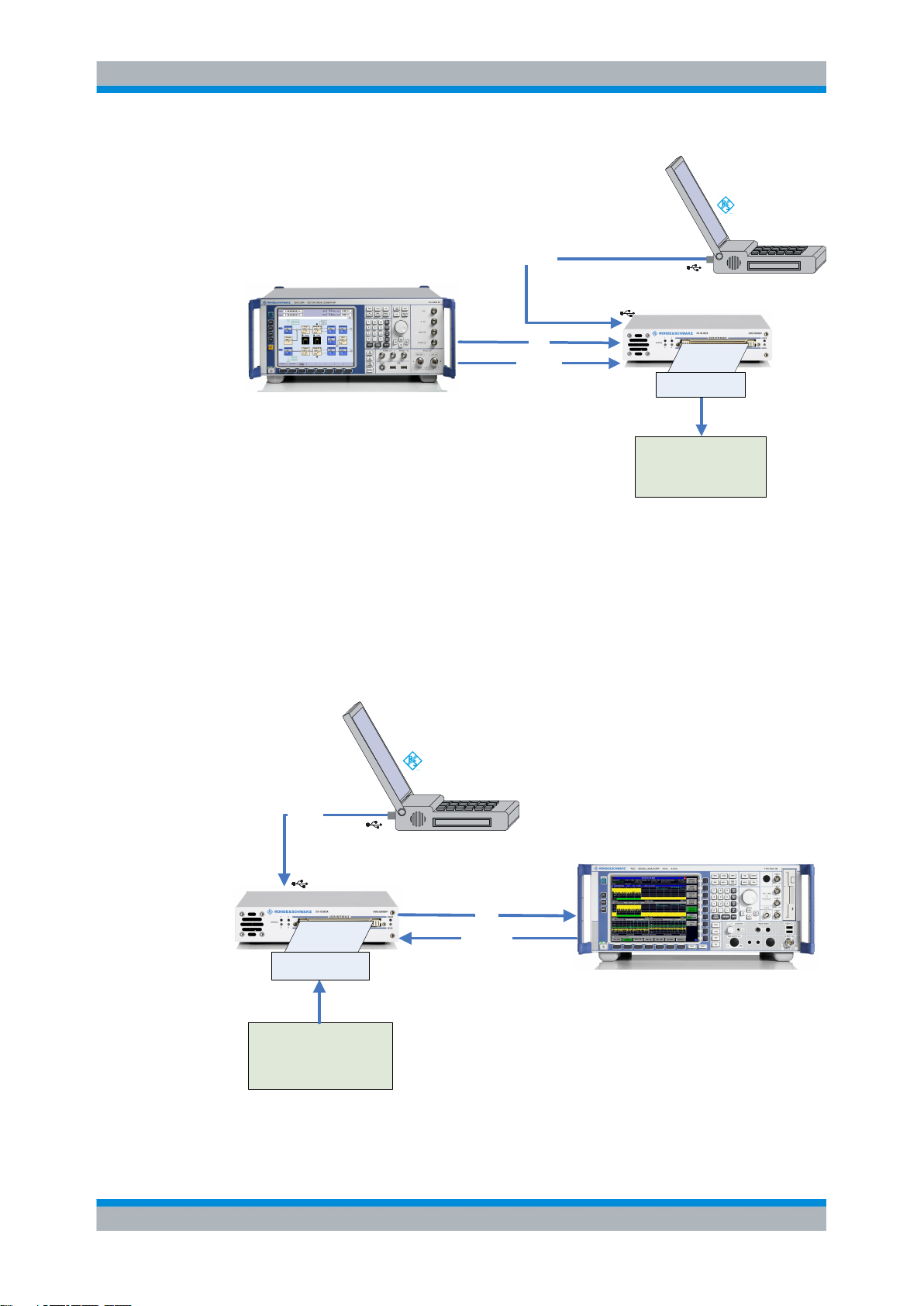
Fig. 3-1: Configuration example with R&S DigIConf
The example represents a basic configuration of the R&S EX-IQ-BOX, operated by the
digital interface configuration software R&S DigIConf via PC.
In this configuration the R&S EX-IQ-BOX operates in transmitter mode from an R&S
instrument to the DUT.
A configuration example of the R&S EX-IQ-BOX working in receiver mode is shown in
the following picture:
Control
USB IN
R&S EX-IQ-BOX
Breakout Board
Fig. 3-2: R&S
R&S DigIConf
USB Host
R&S Instrument
(equipped with digital interface)
IQ OUT
User
Interface
Data
DUT
EX-IQ-BOX and R&S instrument working in receiver mode, controlled by R&S DigIConf
REF IN
Data
Reference
DIG. IQ IN
REF OUT
15User Manual 1409.5570.32 ─ 05
Page 31

R&S®EX-IQ-BOX
System Overview
Basic Operating Modes
3.1.2 R&S Instruments Controlling the R&S EX-IQ-BOX
This operating mode applies to the previous model of the R&S EX-IQ-BOX
1409.5502.02 and User Defined applications.
The R&S EX-IQ-BOX"1409.5505K04" is always controlled by R&S DigIConf.
R&S Instrument
(equipped with digital interface)
USB Host
DIG. IQ OUT IQ IN
REF OUT
Fig. 3-3: Configuration example of the R&S EX-IQ-BOX, directly controlled by an R&S instrument
Control
Data
Reference
USB IN
REF IN
R&S EX-IQ-BOX
User
Interface
Breakout Board
Data
DUT
This example shows a basic configuration of the R&S EX-IQ-BOX 1409.5502.02, working
with an R&S signal generator. The R&S EX-IQ-BOX operates in transmitter mode from
the signal generator to the DUT.
3.1.3 Remote Control of the R&S EX-IQ-BOX
Remote control functionality provides access to the measurement from a remote computer (external controller). By means of remote commands, settings or data are transmitted to the R&S EX-IQ-BOX via R&S DigIConf. Remote programs automate repeated
settings. The remote control programs can either run on the same computer as the
R&S DigIConf or on any PC in the network.
Remote control of R&S DigIConf is performed via a LAN socket communication protocol,
also referred to as Raw Socket communication.
Socket communication uses the TCP/IP network protocol. A VISA installation on remote
controller side is not mandatory. Connection can also be performed with a Win Socket
communication.
If you use a VISA library, the access is more convenient.
16User Manual 1409.5570.32 ─ 05
Page 32

R&S®EX-IQ-BOX
System Overview
Basic Operating Modes
Information on the LAN Connector of the R&S EX-IQ-BOX
Data and settings of the R&S EX-IQ-BOX are controlled via the USB interface. The LAN
connector is intended for future use and it is not possible to directly remote-control the
R&S EX-IQ-BOX via the LAN interface.
For the control, SCPI (Standard Commands for Programmable Instruments) commands
are used.
An introduction to the structure and to the syntax of SCPI commands is given in the
operating manual of the R&S EX-IQ-BOX, see chapter 8, "Remote Control Basics",
on page 213.
3.1.3.1 Remote Control via R&S DigIConf
The remote control program controls R&S DigIConf, which then transmits the settings to
the R&S EX-IQ-BOX via the USB interface. The remote program runs either on the same
PC as the R&S DigIConf software or on any PC in a network.
Examples of the remote controlled R&S DigIConf
● The remote control program and R&S DigIConf run on the same computer.
Remote control program
Adress: Local Host
LAN
Port: 5026
Remote
R&S DigIConf
Fig. 3-4: Remote control program and R&S
The remote connection is looped internally. The computer name, i.e. the IP address
is "Local Host". R&S DigIConf uses port 5026 by default, the port can be set.
● The remote control program and R&S DigIConf run on different computers.
Control
USB
DigIConf running on the same PC
R&S EX-IQ-BOX
17User Manual 1409.5570.32 ─ 05
Page 33

R&S®EX-IQ-BOX
Remote control
program
ipaddr, port
Remote
LAN
ipaddr
port
System Overview
Basic Operating Modes
R&S DigIConf
Fig. 3-5: Remote control program and R&S DigIConf running on different PCs
The LAN connection is established to the computer with R&S DigIConf with a commercial
RJ-45 network cable. IP address and port are assigned accordingly.
For further information on LAN connection and IP address, see chapter 8, "Remote Con-
trol Basics", on page 213.
3.1.3.2 Remote Control via an R&S Instrument
This operating mode applies to the R&S EX-IQ-BOX 1409.5502.02 and User Defined
protocols.
The R&S EX-IQ-BOX 1409.5505K04 is always controlled by R&S DigIConf.
If the R&S EX-IQ-BOX 1409.5502.02 works directly with an R&S instrument, i.e. without
R&S DigIConf, the box is accessed by the instrument via the USB interface. Remote
control is executed via the instrument, i.e. all remote control interfaces of the instrument
can be usesd, as well as all remote-control modes.
Control
USB
R&S EX-IQ-BOX
R&S instruments usually provide remote control via LAN, GPIB, or USB interface. Refer
to the operating manual of your instrument to receive detailed information on the available
remote control interfaces and their use.
See the operating manual of your R&S instrument for detailed information:
For setting up a connection, refer to sections "Connecting the Instrument to a Net-
●
work", and "Manual Remote Control via an External Controller" in chapter "Putting
into Operation".
Chapter "Remote Control - Basics" describes the basics for setting up the instrument
●
for remote control, programming syntax, command processing and the status reporting system.
Chapter "Remote Control - Description of Commands" lists all the remote commands
●
that are defined for the instrument.
18User Manual 1409.5570.32 ─ 05
Page 34

R&S®EX-IQ-BOX
System Overview
Basic Operating Modes
The remote control commands for setting the parameters of the R&S EX-IQ-BOX are
described in the operating manual; see chapter 9.3, "User Defined - Remote Control
Commands", on page 257.
R&S Instrument
(equipped with digital interface)
Remote control
program
GPIB, LAN, ...
Remote
Data
Control
USB
R&S EX-IQ-BOX
Fig. 3-6: Example of remote control of an R&S instrument with a connected R&S EX-IQ-BOX
3.1.4 Waveform Memory, Multi Waveform Playback and Recording Memory
Waveform Memory, Multi Waveform Playback and Recording Memory are performed
with R&S DigIConf and standardized protocols.
The R&S EX-IQ-BOX "1409.5505K04" can also be used without an instrument as an I/
Q source, while a signal is generated in the box by means of a Waveform Memory, or
even a Multi Waveform Playback for simultaneous playback of up to four signals.
19User Manual 1409.5570.32 ─ 05
Page 35

R&S®EX-IQ-BOX
System Overview
Basic Operating Modes
R&S DigIConf
USB Host
Fig. 3-7: Configuration example of the R&S EX-IQ-BOX equipped with a Waveform Memory
Waveform data
Transmitter
mode
Control
Waveform
Memory
R&S EX-IQ-BOX
Breakout Board
Data
DUT
Equipped with the Recording Memory option, the R&S EX-IQ-BOX records received I/Q
signals. With a suitable program, the data can be displayed on a PC and evaluated.
R&S DigIConf
USB Host
Fig. 3-8: Configuration example of the R&S
Waveform data
Control
Receiver
mode
EX-IQ-BOX recording incoming data
R&S EX-IQ-BOX
Breakout Board
Data
DUT
Recording
Memory
20User Manual 1409.5570.32 ─ 05
Page 36

R&S®EX-IQ-BOX
System Overview
Components
The R&S EX-IQ-BOX can execute signal generation from a Waveform Memory and data
recording simultaneously.
3.2 Components
This chapter provides an overview of the available components for test setups with the
R&S EX-IQ-BOX. Hardware and software components and the according part numbers
are listed.
Ordering information as well as latest software and firmware versions are also provided
on the internet at the R&S website:
http://www.rohde-schwarz.com/product/EX-IQ-Box.html
3.2.1 R&S EX-IQ-BOX
Digital Signal Interface module R&S EX-IQ-BOX (part number 1409.5505K04), including:
power supply
●
one USB cable
●
one LVDS cable
●
two breakout boards for User Defined protocols
●
– single ended 090002-22x, type II
– differential 090002-23x, type III
Quick Start Guide
●
● CD-ROM with configuration software R&S DigIConf, data sheet, online help and user
manual
21User Manual 1409.5570.32 ─ 05
Page 37

R&S®EX-IQ-BOX
System Overview
Components
3.2.2 Options
The options concept allows you to individually equip the R&S EX-IQ-BOX according to
the requirements of the application. Additionally, note the following information in order
to configure the R&S EX-IQ-BOX correctly:
Standardized protocols always exist of the option for the hardware (Breakout Board)
●
and one or several options for the software. To enable a standardized protocol order
the respective software option in addition to the hardware option (EXBOX-Bxx +
EXBOX-Kxx).
Waveform Memory, Multi Waveform Playback and Recording Memory can be per-
●
formed only with standardized protocols.
Software options providing digital standards require R&S WinIQSIM2 software and
●
the Waveform Memory or the Multi Waveform Playback.
Standardized protocols, Waveform Memory, Multi Waveform Playback and Record-
●
ing Memory require the R&S EX-IQ-BOX 1409.5505K04 and the configuration software R&S DigIConf.
3.2.2.1 Standardized Protocols
For applications with standardized protocols the following options are available:
Digital Interface Protocol... Option R&S... R&S part number
CPRI Breakout Board (16x) EXBOX-B85 1409.7208.04
CPRI Breakout Board (5x) EXBOX-B85 1409.7208.02
CPRI RE Test EXBOX-K10 1417.1170.02
CPRI REC Test EXBOX-K11 1417.1186.02
Note: Each option is delivered with a licence key for activation.
Standardized protocols require R&S EX-IQ-BOX 1409.5505K04 and the configuration
software R&S DigIConf.
3.2.2.2 User Defined Protocols
In addition to the two breakout boards single ended and differential, which are included
in delivery, the following options are available:
...Breakout board Option R&S... R&S part number
Cadence Palladium ... 090002-24x EXBOX-Z3 1417.3566.02
MDR (Mini Delta Ribbon) ... 090002-25x EXBOX-Z4 1417.3614.02
These options only consist of the breakout boards and are used the same way as the breakout boards types
single ended and differential.
22User Manual 1409.5570.32 ─ 05
Page 38

R&S®EX-IQ-BOX
System Overview
Components
The R&S EX-IQ-BOX 1409.5502.02 provides only User Defined protocols.
3.2.2.3 Waveform Memory, Multi Waveform Playback and Recording Memory
Waveform Memory 64 MS EXBOX-K90 1417.1005.02
Multi Waveform Playback EXBOX-K91 1417.1011.02
Recording Memory 512 MByte EXBOX-K94 1417.1028.02
Option R&S... R&S part number
Waveform Memory, Multi Waveform Playback and Recording Memory require the
R&S EX-IQ-BOX 1409.5505K04 and the configuration software R&S DigIConf.
3.2.2.4 Digital Standards with R&S WinIQSIM2
The following software options providing digital standards are available. The signals generated with the aid of the R&S WinIQSIM2 software can be output by the Waveform
Memory or the Multi Waveform Playback of the R&S EX-IQ-BOX. Digital standards are
provided by the R&S EX-IQ-BOX 1409.5505K04 and the configuration software
R&S DigIConf.
Digital Standard Option R&S... R&S part number
GSM/EDGE EXBOX-K240 1417.1034.02
EDGE Evolution EXBOX-K241 1417.1040.02
3GPP FDD EXBOX-K242 1417.1057.02
3GPP FDD Enhanced EXBOX-K243 1417.1063.02
3GPP FDD HSUPA EXBOX-K245 1417.1070.02
CDMA 2000® incl. 1xEV-DV EXBOX-K246 1417.1086.02
1xEV-DO REV. A EXBOX-K247 1417.1092.02
IEEE 802.16 (WiMAXTM) EXBOX-K249 1417.1111.02
TD-SCDMA EXBOX-K250 1417.1128.02
TD-SCDMA Enhanced EXBOX-K251 1417.1134.02
IEEE 802.11n (WLAN-N) EXBOX-K254 1417.1105.02
EUTRA/LTE EXBOX-K255 1417.1140.02
HSPA+ EXBOX-K259 1417.1157.02
3.2.3 R&S DigIConf - Digital Interface Configurator
The software R&S DigIConf (Digital Interface Configurator for the R&S EX-IQ-BOX)
controls the protocol, data and clock settings of the R&S EX-IQ-BOX independently from
23User Manual 1409.5570.32 ─ 05
Page 39

R&S®EX-IQ-BOX
System Overview
Components
the connected R&S instrument. Besides basic functions of the User Defined protocols,
this software utility supports the settings of the standardized protocol CPRI ; provided
that the appropriate options are available, see chapter 3.2.2, "Options", on page 22.
R&S DigIConf provides:
● the control of the R&S EX-IQ-BOX from a PC, or also from the R&S CMW
● parameter settings of the R&S EX-IQ-BOX 1409.5502.02 for User Defined protocols
● parameter settings of the R&S EX-IQ-BOX 1409.5502K04, for
– User Defined protoocols
– Standardized protocols
data verification and transfer of Waveform Memory, Multi Waveform Playback and
●
Recording Memory
activation of Digital Standards with R&S WinIQSIM2
●
The program is designed to be installed on a PC running a Microsoft® Windows 2000
(SP4) / XP (SP1) / Windows 7 (32/64 bit) operating system. A setup file, included in
delivery, covers an installation wizard, the executable program and all necessary program
and data files.
For information on installation of R&S DigIConf refer to chapter 4.4, "Installing R&S Dig-
IConf", on page 34.
Operating R&S DigIConf is described in the operating manual, chapter 6, "R&S EX-IQ-
BOX Configuration", on page 53.
How to proceed for setting up an option refer to chapter 4.6, "Installing R&S EX-IQ-BOX
Options", on page 44.
Simulation mode
If no R&S EX-IQ-BOX is connected, R&S DigIConf runs in simulation mode. All options
are active, but real operation cannot be performed.
The latest software versions can be downloaded free of charge from the R&S website:
http://www.rohde-schwarz.com/product/EX-IQ-Box.html
3.2.4 Accessories
Various accessories support specific test configurations or modifications.
For example, if you want to connect the R&S EX-IQ-BOX to a second R&S instrument,
you need a second LVDS cable.
Or, if your application requires a specific cable, card or an individual pin assignment, the
user interface connector, the Tyco Z-Dok adapter, is separately available as R&S
EXBOX-Z1.
The breakout board R&S EXBOX-Z2 especially supports direct connection of two
R&S EX-IQ-BOXes, used for example for demo purposes.
24User Manual 1409.5570.32 ─ 05
Page 40

R&S®EX-IQ-BOX
System Overview
Components
A conceivable scenario is for example: An R&S signal generator connected to the first
R&S EX-IQ-BOX, and R&S signal analyzer to the second one. The R&S EX-IQ-BOXes
are connected via the R&S EXBOX-Z2 breakout board.
The signal generator sends an I/Q signal to the first R&S EX-IQ-BOX which forwards this
signal to the second R&S EX-IQ-BOX via the breakout board. With the signal analyzer
you can evaluate and display the transmitted signal.
Accessory Option R&S... R&S part number
LVDS cable for connecting
digital baseband interfaces
Tyco Z-Dok connector,
168 pin (56 differential pairs)
Demo breakout board EXBOX-Z2 1417.3514.02
3.2.5 R&S Instruments Working with the R&S EX-IQ-BOX
SMU-Z6 1415.0201.02
EXBOX-Z1 1409.7437.01
This sections provides an overview of the R&S instruments that work with the R&S EXIQ-BOX, provided that the instrument is equipped with the respective digital interface
option.
Digital interface options of R&S instruments
For detailed information on the digital input and output options of the instruments refer to
the R&S EX-IQ-BOX data sheet, provided on the CD ROM, or the respective operating
manual of your R&S instrument.
Signal Generation
● R&S AMU200A - Baseband Signal Generator and Fading Simulator
● R&S SMU200A - Vector Signal Generator
● R&S SMBV100A - Vector Signal Generator
● R&S SMJ100A - Vector Signal Generator
Signal Analysis
● R&S FMU36 - Baseband Signal Analyzer
● R&S FSV - Signal and Spectrum Analyzer
● R&S FSW - Signal and Spectrum Analyzer
● R&S FSG - Signal Analyzer
● R&S FSQ - Signal Analyzer
Radio Communication
● R&S CMW500 - Universal Wideband Radio Communication Tester
25User Manual 1409.5570.32 ─ 05
Page 41

R&S®EX-IQ-BOX
4 Getting Started
Getting Started
Safety Instructions
This section introduces the control elements and connectors of the R&S EX-IQ-BOX and
explains how to put the device into operation. It encloses installation of the configuration
software R&S DigIConf, installation of options, and connecting the device to an R&S
instrument and the DUT.
4.1 Safety Instructions
General Precautions
Shock hazard
Do not open the device casing. As a rule, normal operation of the device does not require
opening the casing. Observe the general safety instructions and regulations at the beginning of the manual.
Risk of device damage
Note that the general safety instructions also contain information on operating conditions
that will prevent damage to the device. The device's data sheet may contain additional
operating conditions.
Before putting the device into operation, make sure that the following conditions are met:
All fan openings are unobstructed and the airflow perforations are unimpeded. The
●
minimum distance from the wall is 10 cm.
The device is dry and shows no sign of condensation.
●
The interfaces of the device are correctly connected.
●
The device is operated in the horizontal position on an even surface.
●
The ambient temperature does not exceed the range specified in the data sheet.
●
Signal levels at the input and output connectors are all within the specified ranges.
●
Failure to meet these conditions may cause damage to the R&S EX-IQ-BOX or other
devices in the test setup.
26User Manual 1409.5570.32 ─ 05
Page 42

R&S®EX-IQ-BOX
Getting Started
Safety Instructions
Risk of injury and instrument damage if stacking instruments
A stack of instruments may tilt over and cause injury and material damage because the
instrument's top surface area is too small.
Never stack instruments on top of each other. If you need to stack instruments, install
them in a rack.
Protection against Connector Overload
Avoid connector overload
The type of the electrical signals are based on various logic types (TTL or CMOS standard) performing different logic levels. The logic type of the connected DUT must be compatible to the set logic type of the R&S EX-IQ-BOX. Inappropriate logic types may cause
damage to the R&S EX-IQ-BOX or to the DUT.
Make sure that the signal level is compatible to the set logic type and does not exceed
the permissible limits.
Follow the allowed maximum values, listed in the data sheet!
As soon as a protocol is activated or the logic type is changed during the operation, the
following warning message appears:
The setting is executed only after confirmation of the warning message.
27User Manual 1409.5570.32 ─ 05
Page 43

R&S®EX-IQ-BOX
Getting Started
Safety Instructions
Protection against Electrostatics
Risk of electrostatic discharge
Protect the work area against electrostatic discharge to avoid damage to the electronic
components in the modules. For details, refer to the safety instructions at the beginning
of this manual.
EMI Suppression
Electromagnetic interference (EMI) may affect the measurement results.
To suppress generated electromagnetic interference (EMI):
Use suitable double shielded LAN (CAT 7), SMA and BNC cables of high quality.
●
All connected cables must not exceed 3m in length.
●
All unconnected outputs and lines have to be terminated properly with 50 Ohms.
●
Use only the USB cable included in delivery.
●
Note: USB cables are of varying and often poor quality. Therefore, it is recommended
that you use only the supplied USB cable.
Use only the power supply included in delivery.
●
Use the cable R&S SMU-Z6 for connection to the DIG I/Q interfaces of the instrument.
●
The required cable is available under part number 1415.0201.02.
Note the EMC classification in the data sheet.
●
Power supply
Danger of instrument damage when using a power supply other than specified!
Use only with the approved power supply of type:
Vendor: CINCON ELECTRONICS CA., LTD.
Model: TR45A05-11A01
Input: 100-240VAC 1.5A 50-60Hz
Output: 5VDC 6.0A
The R&S EX-IQ-BOX must not be specially switched on or switched off, but is ready for
operation after connection of the power supply and the USB. Also the device is powered
off while the USB connection is disconnected and the net plug is pulled.
28User Manual 1409.5570.32 ─ 05
Page 44

R&S®EX-IQ-BOX
Getting Started
Unpacking the R&S EX-IQ-BOX
4.2 Unpacking the R&S EX-IQ-BOX
To remove the device from its packaging and check the equipment for completeness
proceed as follows:
1.
Remove the R&S EX-IQ-BOX and the various components from their packaging.
2. Check the equipment for completeness using the delivery list.
3. Check the device for any damage. If there is damage, immediately contact the carrier
who delivered the device. Make sure not to discard the box and packing material.
Packing material
Retain the original packing material. If the R&S EX-IQ-BOX needs to be transported or
shipped at a later date, you can use the material to prevent control elements and connectors from being damaged.
Risk of injury and instrument damage if stacking instruments
A stack of instruments may tilt over and cause injury and material damage because the
instrument's top surface area is too small.
Never stack instruments on top of each other. If you need to stack instruments, install
them in a rack.
4.3 Control Elements and Connectors
This section explains the control elements and connectors of the R&S EX-IQ-BOX with
the aid of the front and rear views.
29User Manual 1409.5570.32 ─ 05
Page 45

R&S®EX-IQ-BOX
Getting Started
Control Elements and Connectors
4.3.1 Front Panel Tour
This section gives an overview of the control elements and the connectors at the front
panel of the R&S EX-IQ-BOX. Each element/connector is briefly described and a reference is given to the chapters containing detailed information.
Fig. 4-1: Front panel view
4.3.1.1 STATUS - LEDs
1 Status LED for DIG I/Q IN/OUT 1
Green: the interface is active.
●
Yellow: the interface is initializing.
●
Off: the interface is not connected.
●
2 Status LED for DIG I/Q IN/OUT 2
Green: the interface is active.
●
Yellow: the interface is initializing.
●
Off: the interface is not connected.
●
3 Status LED for PLL (Phase Locked Loop)
Green: the PLL is active and locked.
●
Yellow: the PLL is active and unlocked.
●
Off: the PLL is switched off.
●
4 Status LED of the breakout board
Green: the breakout board is active.
●
Yellow: the breakout board is connected.
●
Off: the breakout board is not connected.
●
30User Manual 1409.5570.32 ─ 05
Page 46

R&S®EX-IQ-BOX
Getting Started
Control Elements and Connectors
4.3.1.2 User Interface
Fig. 4-2: TYCO Z-Dok adapter board connector, 56 differential pairs
See chapter 10.1.1, "Z-DOK-Adapter Board Connector", on page 355.
User interface for serial or parallel transmission of digital I/Q data (up to 20 bit wide data
bus), data clock and control signals, connected by a 168 pin connector, type TYCO ZDok (56 differential pairs).
This interface is used to connect the breakout boards.
4.3.1.3 MODE - LED
The MODE LED indicates current activities of the R&S EX-IQ-BOX.
Green blinking: the configuration file (application specific image) is loading.
●
Green continuous: the configuration file (application specific image) is currently
●
active. Data transmission is possible.
Yellow blinking: the initialization (initial image) is loading.
●
Yellow continuous: the initialization (initial image) is currently active.
●
Off: there is no configuration file loaded. Therefore, data transmission is not possible.
●
4.3.1.4 ERROR - LED
The ERROR LED indicates an error of the R&S EX-IQ-BOX.
Off : no error occurred.
●
● Red: an error has been detected. R&S DigIConf or the connected R&S instrument
display an error message.
31User Manual 1409.5570.32 ─ 05
Page 47

R&S®EX-IQ-BOX
Getting Started
Control Elements and Connectors
4.3.2 Rear Panel View
This section gives an overview of the control elements and the connectors on the rear
panel of the R&S EX-IQ-BOX. Each element/connector is briefly described and a reference is given to the chapters containing detailed information.
Fig. 4-3: Rear panel view
4.3.2.1 REF IN - Reference signal input
BNC connector for input of a reference signal provided by the R&S instrument.
4.3.2.2 IN / OUT - LED
The interface LEDs indicate the operating mode of the digital interfaces.
Green: the interface is operating in input mode.
●
Yellow: the interface is operating in output mode.
●
4.3.2.3 DIG I/Q IN/OUT2, 1 - Digital interfaces
32User Manual 1409.5570.32 ─ 05
Page 48

R&S®EX-IQ-BOX
Getting Started
Control Elements and Connectors
Connectors for the input or output of the digital I/Q signal. The R&S EX-IQ-BOX covers
two digital interfaces; both ports can be used for either signal input or output.
One cable for the connection between the digital I/Q interfaces of the R&S EX-IQ-BOX
and an R&S instrument is included in delivery. Additional cables are available separately.
Refer to chapter 3.2.4, "Accessories", on page 24 for the R&S part number of the associated cable.
4.3.2.4 LAN - Interface
The LEDs at the top indicate activity and status of the interface.
Green: a link is active.
●
Yellow: transmission is active.
●
The LAN connector is intended for future use and it is not possible to directly remotecontrol the R&S EX-IQ-BOX via this interface. Data and settings of the R&S EX-IQ-BOX
are controlled via the USB interface.
The R&S EX-IQ-BOX is connected to the LAN with the aid of a commercial RJ-45 CAT7
cable. The interface supports 10/100/1000Mbps Ethernet IEEE 802.3u.
4.3.2.5 USB IN - USB interface type B
Universal Serial Bus interface of type B (device "USB"). This port is used for communi-
cation with the host instrument.
The interface supports two data rates:
High-speed data rate of 480 Mbit/s.
●
Full-speed rate of 12 Mbit/s.
●
An USB cable for the connection is included in delivery.
33User Manual 1409.5570.32 ─ 05
Page 49

R&S®EX-IQ-BOX
Getting Started
Installing R&S DigIConf
4.3.2.6 POWER - Power supply
The R&S EX-IQ-BOX is supplied with an external power supply unit and a separate power
cable, see chapter 4.5, "Connecting the R&S EX-IQ-BOX", on page 42.
The Power LED indicates the different operating states of the device, depending on the
state of the external voltages.
OFF: the external power supply unit is not connected ("Power Off state").
●
Yellow: the main power of the device is on but the USB power is off (Standby
●
state).
Green: the main power and the USB power are on. The device is ready for operation.
●
4.4 Installing R&S DigIConf
This section describes how to install the software R&S DigIConf (Digital Interface
Configurator), the tool for controlling the protocol settings of the R&S EX-IQ-BOX. It also
encloses the hardware and software requirements which have to be met for installation.
Software and Hardware Requirements
It is recommended that your PC fulfills the following minimum requirements:
Component Minimum requirement
Operating system Windows 2000 SP4 / XP SP1 (32 bit), Windows 7
CPU Pentium 4, 1 GHz or higher
RAM 256 MB
Hard disk 100 MByte free space
Monitor XGA monitor (1024 x 768)
Interfaces USB 2.0
Tip: USB 1.1 is also supported, but due to the lower transmission speed, it is
recommended to operate with USB 2.0.
For some Rohde & Schwarz instruments, e.g. the R&S CMW500, it is possible to install
R&S DigIConf directly on the instrument. The operating manual of the instrument states
if the instrument supports this mode of operation. The installation on the instrument is the
same as on the PC, see below.
34User Manual 1409.5570.32 ─ 05
Page 50

R&S®EX-IQ-BOX
Getting Started
Installing R&S DigIConf
Prerequisites
● Uninstall the old software version, as described in chapter 4.4.3, "Uninstalling",
on page 38.
Close any running applications.
●
● Disconnect all R&S EX-IQ-BOXes and do not connect any during installation.
4.4.1 Installation
The setup file DigIConf_x.xx.xxx.exe for the installation of the R&S DigIConf is included
in the delivery of your R&S EX-IQ-BOX or can be downloaded from the R&S website:
http://www.rohde-schwarz.com/product/EX-IQ-Box.html
► Execute DigIConf_x.xx.xxx.exe
in the windows explorer and follow the installation instructions of the R&S DigIConf
setup wizard.
The version number x.xx.xxx in the filename represents the current version. Each
update has a new release number.
During installation the program creates various subdirectories needed by the application.
Additionally, the installation wizard checks the status of the registry entry "DisableCAD"
in order to exclude logon conflicts during later operation. The wizard prompts you to
modify the DisableCAD status accordingly, in order to fix these conflicts.
Fig. 4-4: R&S
"Yes"
●
DigIConf Installation > Modify DisableCAD
Accept modification.
The installation wizard sets DisableCAD=0 in the registry.
[HKEY_LOCAL_MACHINE\SOFTWARE\Microsoft\Windows\CurrentVersion
\policies\system]"DisableCAD"=dword:00000000
A connected R&S EX-IQ-BOX does not cause any conflicts at startup and logon.
"No"
●
Reject modification.
The parameter DisableCAD remains 1 and you must disconnect the R&S EX-IQBOX before every login and connect it afterwards again.
Backgound: Depending on this registry entry, a connected R&S EX-IQ-BOX may cause
an infinite loop at the Windows logon prompt. It occurs during a logon because Windows
interprets the internal SmartCard of the R&S EX-IQ-BOX as a medium for login. You find
more details also in chapter 4.4.4, "Known Restrictions on SmartCard Related Issues",
on page 39.
35User Manual 1409.5570.32 ─ 05
Page 51

R&S®EX-IQ-BOX
Getting Started
Installing R&S DigIConf
It is recommended that you accept modification.
However, it is also possible, to modify the status later on. The installation wizard prepares
the respective entries for a later modification.
In the last installation window the setup wizard provides a shortcut to the desktop and
you can run R&S DigIConf.
4.4.2 Starting
R&S DigIConf can either be started via:
the menu item "Start > Programs > R&S DigIConf > DigIConf_x.xx.xxx",
●
●
by starting DigIConf.exe in the MS®Windows explorer, located in the prgram files
directory, %Program Files%\Rohde-Schwarz\DigIConf
or via
the "application icon" on the desktop.
●
Startup takes several seconds. At runtime a startup window is indicated until the software
is ready for operation. After startup, the R&S DigIConf main application window is displayed.
36User Manual 1409.5570.32 ─ 05
Page 52

R&S®EX-IQ-BOX
Getting Started
Installing R&S DigIConf
Fig. 4-5: R&S DigIConf main application window
The main application window shows the current configuration and the signal flow in form
of a block diagram.
Depending on the test configuration different elements are indicated. For example, if the
R&S EX-IQ-BOX is connected with an R&S instrument, R&S DigIConf shows a separate
function block with information about the connected instrument. Input/Output symbols in
the block diagram show the currently used inputs and outputs and the lines indicate the
signal flow.
The following pictures show an example of how R&S DigIConf adjusts the display accord-
ing to the test configuration. If several boxes are connected, the respective test configuration is indicated for every R&S EX-IQ-BOX.
Fig. 4-6: R&S
DigIConf display of the R&S EX-IQ-BOX connected to an R&S AMU200A
Fig. 4-7: R&S DigIConf display of the R&S EX-IQ-BOX connected to an R&S FSQ-26
37User Manual 1409.5570.32 ─ 05
Page 53

R&S®EX-IQ-BOX
Getting Started
Installing R&S DigIConf
Fig. 4-8: R&S DigIConf display of the R&S EX-IQ-BOX operating in bidirectional mode
For a detailed description of the application window and its elements refer to the operating
manual, chapter 6.1, "R&S DigIConf Configuration Software", on page 53.
4.4.3 Uninstalling
Uninstall the software with the aid of R&S DigIConf uninstaller,
1. "Start > Programs > R&S DigIConf > Uninstall"
or the PC's control panel,
2. "Start > Settings > Control Panel" in the Windows task bar and open the "Add or
Remove Programs" dialog. Uninstall the program with "Remove".
The uninstall routine identifies all currently installed R&S DigIConf components,
including the relevant files, such as files with user-specific settings.
Before uninstalling, the program asks whether you want to delete the settings directory as well.
3. Confirm or reject, and start uninstalling.
38User Manual 1409.5570.32 ─ 05
Page 54

R&S®EX-IQ-BOX
Getting Started
Installing R&S DigIConf
The uninstaller removes all currently installed R&S DigIConf software items.
After completion the uninstall process is confirmed and can be finished with OK.
If you have decided to keep the preference files, the respective directories of DigIConf
remain.
4.4.4 Known Restrictions on SmartCard Related Issues
If a R&S EX-IQ-BOX is connected while the computer is locked, login can be performed
without any conflicts coming up. But if a R&S EX-IQ-BOX is already connected and you
want to log in, the following "Logon Message" appears:
39User Manual 1409.5570.32 ─ 05
Page 55

R&S®EX-IQ-BOX
Getting Started
Installing R&S DigIConf
Fig. 4-9: R&S DigIConf Installation > Logon message
Windows interprets the internal SmartCard of the R&S EX-IQ-BOX as a medium for login
and therefore causes this message.
When trying to confirm, the system reacts in different ways, depending on the status of
the "DisableCAD" registry entry:
1. "Logon Message" remains
The system repeats the SmartCard error message and blocks the login. DisableCAD=1, i.e. the Windows security attention sequence (CTR-ALT-Del) for login is
skipped. Windows tries to log in with the smart card and fails.
To terminate:
a)
Disconnect the R&S EX-IQ-BOX to enable login.
b) Log in.
c)
Connect the R&S EX-IQ-BOX again.
Note: To solve this conflict for later operation, deactivate DisableCAD in the registry.
The DisableCAD parameter determines whether you need to press CTRL+ALT
+DEL keys to log in, or whether the login window directly appears after at startup or
after locked desktop.
2. "Logon Message" disappears
The system forwards to the "Computer Locked" dialog box. In this case, DisableCAD=0, Windows requires users to press CTR-ALT-Del (security attention
sequence) for login.
a) Press CTRL+ALT+DEL to unlock the computer and log in as usual.
The connection to the R&S EX-IQ-BOX may remain.
4.4.4.1 How to avoid the SmartCard Conflict
The only way to avoid the conflict reliably, is to set DisableCAD=0. If the setting has not
been modified yet, proceed as follows.
To modify this registry entry, R&S DigIConf provides the file DisableCAD.reg in the
directory:
%APPDATA%\Rohde-Schwarz\DigIConf\Registry
► Execute DisableCAD.reg to deactivate the setting, i.e. to enable the "Press Ctrl-
Alt-Del" security attention sequence.
The entry is automatically set to 0. Login can now be performed with connected
R&S EX-IQ-BOXes without conflicts.
40User Manual 1409.5570.32 ─ 05
Page 56

R&S®EX-IQ-BOX
Getting Started
Installing R&S DigIConf
R&S DigIConf also provides the file EnableCAD.reg in the installation directory to disable the sequence accordingly.
4.4.4.2 DisableCAD - Background Information
The DisableCAD parameter determines whether you must press the (CTRL+ALT+DEL)
security attention sequence for windows login, or whether the login window directly
appears after startup or after locked desktop.
DisableCAD=0
●
This status requires users first to press CTRL+ALT+DEL, the windows security attention sequence to access the Windows login dialog box.
Fig. 4-10: Windows security attention sequence check box
The Windows dialog box opens, as shown below.
DisableCAD=1
●
The Windows login dialog box appears immediately after booting, or locked desktop.
41User Manual 1409.5570.32 ─ 05
Page 57

R&S®EX-IQ-BOX
Getting Started
Connecting the R&S EX-IQ-BOX
Fig. 4-11: Windows login dialog box
The require users to "Press Ctrl-Alt-Del" check box is skipped.
4.5 Connecting the R&S EX-IQ-BOX
This section describes how to connect the R&S EX-IQ-BOX in principle, i.e. to the power
supply, to a PC, an R&S instrument and to the DUT. Connection and startup require no
particular order, but it is recommended that you follow the procedure as described below.
Connection
It is assumed that all R&S instruments in the test setup are properly power supplied and
switched on.
1. Power supply
Power supply: 30 W switching power supply adapter with an input voltage of
100 to 240 VAC.
The R&S EX-IQ-BOX is power supplied with an external power supply unit and a separate
power cable. The external power supply unit provides all required voltages of the hardware.
►
Connect the R&S EX-IQ-BOX to the AC supply.
The R&S EX-IQ-BOX is in ready state, if USB is already connected (POWER LED
= green). Without USB connection the device R&S EX-IQ-BOX is in standby state
(POWER LED = yellow).
42User Manual 1409.5570.32 ─ 05
Page 58

R&S®EX-IQ-BOX
Getting Started
Connecting the R&S EX-IQ-BOX
The device is still power-supplied while it is in standby mode.
2. USB Connection
To establish a connection between the R&S EX-IQ-BOX and a PC or an R&S instrument
(R&S EX-IQ-BOX 1409.5502.02), proceed as follows:
1.
Connect the USB cable plug B to the R&S EX-IQ-BOX USB IN
2. Connect the USB cable plug A to the PC or to the instrument
Device driver
If the R&S EX-IQ-BOX is connected for the first time, the Windows Hardware Wizard
requires the installation of the appropriate device driver. The same applies if you install
a new update of R&S DigIConf.
Follow the wizard instructions until windows has finished the driver installation. If the
installation is finished, a message is displayed in the info line.
The software drivers need to be installed only once for a device. Due to the operation
mode of USB, every new R&S EX-IQ-BOX needs a driver installation.
3. Data signal connection
1. Establish the connection for the reference frequency.
a)
Connect the coaxial cable to REF IN-BNC connector of the R&S EX-IQ-BOX.
b) Connect the coaxial cable to REF OUT of the instrument.
2. Establish the digital interface connection.
a) Transmitter Mode
Connect the LVDS cable between the R&S EX-IQ-BOX (DIG I/Q IN/OUT 2) and
the BASEBAND DIGITAL IN of the R&S instrument
b) Receiver Mode
Connect the LVDS cable between the R&S EX-IQ-BOX "DIG I/Q IN/OUT 2" connector and the "BASEBAND DIGITAL IN" of the R&S instrument.
43User Manual 1409.5570.32 ─ 05
Page 59

R&S®EX-IQ-BOX
Getting Started
Installing R&S EX-IQ-BOX Options
On connecting the LVDS cable the R&S instruments and the R&S EX-IQ-BOX detect
the connection established between them. Depending on the instrument the indication for a successful connection differs, it is either a short message in the info line or
a graphical message.
4. Connection to the DUT
1. Connect the respective breakout board (USER INTERFACE).
2. Establish the appropriate connection to the DUT.
4.6 Installing R&S EX-IQ-BOX Options
This section explains how to install an option of the R&S EX-IQ-BOX.
Prerequisites
Before installing an option, make sure that the R&S EX-IQ-BOX is power supplied and
an USB connection is established.
Keep the license key ready that is provided with the software option.
Installation
The software options are installed on the R&S EX-IQ-BOX using R&S DigIConf.
1.
Start R&S DigIConf.
2. In the "Tools" menu, select "Tools > EX-IQ-BOX Device Manager".
The "EX-IQ-BOX Device Manager" dialog opens.
44User Manual 1409.5570.32 ─ 05
Page 60

R&S®EX-IQ-BOX
Getting Started
Installing R&S EX-IQ-BOX Options
The hardware tab indicates various information on a selected device, like part number, serial number, firmware version, and so on.
3. In the "Options" tab, select the appropriate "EX-IQ-BOX Device".
The list box lists each connected R&S EX-IQ-BOX.
45User Manual 1409.5570.32 ─ 05
Page 61

R&S®EX-IQ-BOX
Getting Started
Installing R&S EX-IQ-BOX Options
For detailed description on this dialog refer to chapter 6.1.6.1, "EX-IQ-BOX Device
Manager", on page 65 in the operating manual.
4. To enter the license key, perform one of the follwoing:
● in the "Enter License Key" text box, enter the license key code manually.
● Select "Import License Key from File", and proceed accordingly.
5. Enter the license key provided with the option in the "Option-Key" field and confirm
with "Enter".
6. Confirm with "OK".
R&S DigIConf immediately shows the newly enabled option in the table.
Installing several options
Just repeat step 3 to install more options on the same device or steps 2 and 3 to install
options on other devices.
Checking for installed options
To check installed options proceed as follows:
1. Open the "EX-IQ-BOX Device Manager" dialog.
2.
Select the R&S EX-IQ-BOX from "EX-IQ-BOX Device".
The installed options are displayed in the "Installed Options" table.
46User Manual 1409.5570.32 ─ 05
Page 62

R&S®EX-IQ-BOX
5 Application Examples
Application Examples
Baseband Receiver Chip Test
This chapter covers some application examples. The test setups show the R&S EX-IQBOX controlled by R&S DigIConf. Applications with User Defined Interface transmission
protocols also support the direct control of the R&S EX-IQ-BOX by R&S Instruments.
Standardized interface protocols always require the configuration by R&S DigIConf.
5.1 Baseband Receiver Chip Test
Example of the generation of a standards-compliant digital baseband signal for checking
the quality of a receiver.
R&S Signal Generator
Digital IQ data
R&S
Fading
Noise
Impairments
Reference
Transmitter
mode
IQ format
R&S EX-IQ-BOX
Breakout board
Digital IQ
data
R&S DigIConf
USB control
Clock
specific IQ format
Digital baseband
Fig. 5-1: Application example of a baseband receiver chip test
BB Chip
An R&S signal generator together with the R&S EX-IQ-BOX provides digital baseband
signals for all important mobile radio and wireless digital standards such as EUTRA/LTE,
3GPP, HSPA, GSM/EDGE, WiMAX IEEE 802.16 and WLAN IEEE 802.11n. All signal
generator functions are also available for generating digital baseband signals, plus all
signal processing functions to yield effects such as fading, AWGN or I/Q impairments.
This allows measurements on baseband receiver chips to be performed accurately and
47User Manual 1409.5570.32 ─ 05
Page 63

R&S®EX-IQ-BOX
Application Examples
CPRI Test Setup
reproducibly. With the aid of bit and block error ratio measurements the quality of the
receiver can be tested.
5.2 CPRI Test Setup
The following test setups show two typical CPRI test scenarios with the R&S EX-IQ-BOX.
First, the R&S EX-IQ-BOX emulates the baseband module, and in the other example, it
acts as the RF part.
5.2.1 Typical CPRI RE Test Setup
Example of a typical CPRI RE (Radio Equipment = RF unit) test scenario, where the
R&S EX-IQ-BOX acts as a baseband module REC (Remote Equipment Control).
The test setup requires the CPRI breakout board, option R&S EXBOX-B85, the CPRI RE
Test, option R&S EXBOX-K10 and the configuration software R&S DigIConf. For details
on available options, see chapter 3.2.2.1, "Standardized Protocols", on page 22.
R&S SMU200A
Reference
Digital IQ data
Transmitter
R&S FSQ
Receiver
R&S
IQ format
R&S
IQ format
R&S DigIConf
USB control
Bidirectional
mode
R&S EX-IQ-BOX
Breakout board
Optical or
electrical link
CPRI link
Downlink
TX
CPRI RE
(Radio Equipment)
RX
RFBaseband
Uplink
Fig. 5-2: Application example of a RE test setup with the digital interface protocol CPRI
R&S FSQ
Receiver
R&S SMU200A
Transmitter
48User Manual 1409.5570.32 ─ 05
Page 64

R&S®EX-IQ-BOX
Application Examples
CPRI Test Setup
The test setup covers the downlink and the uplink. It provides testing both directions either
simultaneously, i.e. full duplex, or uplink and downlink seperately.
The downlink signal flow
The R&S baseband signal generator feeds a baseband signal (e.g. an LTE downlink) in
the R&S specific I/Q format to the R&S EX-IQ-BOX. The R&S EX-IQ-BOX converts the
R&S I/Q format into the CPRI protocol. The CPRI link transmits the I/Q baseband signal
and control & management information from the R&S EX-IQ-BOX to the DUT, in this case
the CPRI RE Device.
The CPRI RE device extracts the baseband signal from the CPRI link and executes an
I/Q modulation to a certain carrier frequency RF. The resulting RF signal is sent to the
R&S spectrum-analyzer, to perform various measurements, e.g. ACP (Adjacent Channel
Power) or EVM (Error Vector Magnitude) evaluation.
The uplink signal flow
The R&S vector signal generator feeds an RF signal (e.g. an LTE uplink) via the antenna
input into the CPRI RE device. The DUT converts the signal from RF to baseband and
transmits the baseband signal by using the CPRI link.
The R&S EX-IQ-BOX extracts the I/Q baseband signal from the CPRI protocol and sends
the signal in the R&S specific I/Q format to the R&S signal analyzer for demodulation.
All settings regarding the baseband signal (e.g. LTE) are directly controlled by the R&S
signal generator and analyzer, respectively.
CPRI settings like I/Q mapping or link settings are controlled by the configurator software
R&S DigIConf .
In addition to the I/Q data, C&M (Control and Management) information is embedded in
the CPRI protocol. These parameters are also set with the aid of R&S DigIConf.
An Ethernet connector provides fast C&M, and the R&S DigIConf inline text console can
be used for slow C&M.
5.2.2 Typical CPRI REC Test Setup
Example of a typical CPRI REC (Radio Equipment Control = baseband unit) test scenario,
where the R&S EX-IQ-BOX acts as a RF module RE (Remote Equipment).
The test setup requires the CPRI breakout board, option R&S EXBOX-B85, the CPRI
REC Test, option R&S EXBOX-K11 and the configuration software R&S DigIConf. For
details on available options, see chapter 3.2.2.1, "Standardized Protocols", on page 22.
49User Manual 1409.5570.32 ─ 05
Page 65

R&S®EX-IQ-BOX
Application Examples
CPRI Test Setup
R&S DigIConf
USB control
Bidirectional
Downlink
CPRI REC
(Radio Equipment Control)
Uplink
R&S FSQ
R&S
Digital IQ data
Digital IQ data
Reference
Receiver
(downlink)
R&S SMU200A
Transmitter
(uplink)
R&S
IQ format
IQ format
R&S EX-IQ-BOX
mode
Breakout board
Optical or
electrical link
CPRI link
Baseband
Fig. 5-3: Application example of a REC test setup with the digital interface protocol CPRI
The test setup covers the downlink and the uplink. It provides testing both directions either
simultaneously, i.e. full duplex, or uplink and downlink separately.
The downlink signal flow
The DUT, in this case the CPRI REC device, generates a digital baseband signal (e.g.
an LTE downlink) and transmits this signal over the CPRI link.
The R&S EX-IQ-BOX extracts the I/Q baseband signal from the CPRI protocol and sends
the signal in the R&S specific I/Q format to the R&S signal analyzer for demodulation.
The R&S signal analyzer features various measuring methods, as e.g. ACP (Adjacent
Channel Power) or EVM (Error Vector Magnitude) evaluation. Use this measurement
methods to examine the validity and quality of the digital baseband signal, or to evaluate
the influence of numerical imperfections, e.g. quantization effects depending on the I/Q
resolution.
The uplink signal flow
The R&S signal generator feeds an UE uplink signal (e.g. an LTE uplink) in the R&S
specific I/Q format to the R&S EX-IQ-BOX.
The R&S EX-IQ-BOX converts the R&S I/Q format into the CPRI protocol. The CPRI link
transmits the I/Q baseband signal and control & management information from the
R&S EX-IQ-BOX to the DUT, in this case the CPRI REC device.
The DUT must now be able to demodulate the UE uplink signal. Use the various functionalities of the R&S signal generator, e.g. add Channel Fading, AWGN (Additive White
Gaussian Noise) and I/Q impairments in order to perform a very powerful and realistic
receiver / demodulator measurement with this test scenario.
50User Manual 1409.5570.32 ─ 05
Page 66

R&S®EX-IQ-BOX
Application Examples
In-Circuit Emulation for Wireless Designs
All settings regarding the baseband signal (e.g. LTE) are directly controlled by the R&S
signal generator and analyzer, respectively.
CPRI settings like I/Q mapping or link settings are controlled by the configurator software
R&S DigIConf.
In addition to the I/Q data, "C&M" (Control and Management) information is embedded
in the CPRI protocol. These parameters are also set with the aid of R&S DigIConf.
An Ethernet connector provides fast C&M, and a RS-232-C connector provides slow C&M
in real time.
5.3 In-Circuit Emulation for Wireless Designs
The following test setup example requires the Cadence Palladium Breakout Board, option
R&S EXBOX-Z3, and the configuration software R&S DigIConf.
The following example shows a test setup for the emulation of a chip in a software model:
R&S CMW500 Protocol Tester
Digital
IQ data
Uplink
R&S IQ format
Downlink
Frequency reference
R&S IQ format
Frequency reference
Digital IQ data
USB control
R&S EX-IQ-BOX
Breakout Board
R&S EX-IQ-BOX
Breakout Board
Clock
IQ data
IQ data
Clock
USB control
Specific IQ format
Specific IQ format
R&S DigIConf
Fig. 5-4: Application example of an in-circuit emulation of wireless designs
This test setup shows an R&S CMW500, equipped for protocol testing which creates an
I/Q signal. The signal is then converted by an R&S EX-IQ-BOX and fed to the emulator.
A second R&S EX-IQ-BOX converts the incoming signal from the emulator and feeds it
into the baseband section of the R&S potocol tester. Both R&S EX-IQ-BOX devices are
controlled by R&S DigIConf. For detailed information on this application refer to the oper-
51User Manual 1409.5570.32 ─ 05
Page 67

R&S®EX-IQ-BOX
Application Examples
In-Circuit Emulation for Wireless Designs
ating manual of the protocol tester, and the to http://www.rohde-schwarz.com/appnote/
1CM75 on the internet.
52User Manual 1409.5570.32 ─ 05
Page 68

R&S®EX-IQ-BOX
6 R&S EX-IQ-BOX Configuration
R&S EX-IQ-BOX Configuration
R&S DigIConf Configuration Software
The versatile functionality of the R&S EX-IQ-BOX and its options provide convenient
adjustment for signal transmission between different digital interfaces and communication protocols. It supports both user defined protocols or the standardized transmission
protocol CPRI.
The configuration software R&S DigIConf enables you to configure and control the
R&S EX-IQ-BOX via PC. Some R&S instruments, as e.g. the R&S CMW500, also provide
installing R&S DigIConf on the instrument directly. Check in the operating manual to see
if your R&S instrument supports this mode of operation. Refer to chapter 3.1, "Basic
Operating Modes", on page 14 for description in detail.
The R&S EX-IQ-BOX, model 1409.5505.02, additionally supports direct control from an
R&S instrument in User Defined mode. Due to the enhanced capabilities of the R&S EX-
IQ-BOX 1409.5505K04, this model is controlled by R&S DigIConf exclusively, since it
supports all applications.
The following references lead you to the appropriate descriptions for using R&S DigIConf,
and configuring the R&S EX-IQ-BOX for the respective applications:
● R&S DigIConf Configuration Software, comprises the graphical user interface and
basic functionalities of R&S DigIConf, including configuration dialogs and basic information on remote control.
Note: The latest software versions can be downloaded free charge from the R&S
website:
http://www.rohde-schwarz.com/product/EX-IQ-Box.html
● Configuration via R&S Instruments covers all specific characteristics of an R&S
instrument in conjunction with an R&S EX-IQ-BOX1409.5505.02, separately described for every instrument family. E.g. the indication of the R&S EX-IQ-BOX in an
instrument and access to the parameters of the R&S EX-IQ-BOX in an instrument´s
dialog. This constellation applies to User Defined applications.
Separate chapters contain protocol settings of the specific operating modes:
● chapter 7.1, "User Defined", on page 95 covers the parameters and settings for
serial or parallel transmission of I/Q signals, including clock modes, data rates and
logical signal levels.
● chapter 7.2, "CPRI", on page 126 covers explanations and the description to this
standardized protocol.
6.1 R&S DigIConf Configuration Software
This chapter describes the graphical user interface of R&S DigIConf, including the layout
of the application window, the display, controls and how to operate the configuration
software R&S DigIConf. Additionally the chapter contains information on special features
53User Manual 1409.5570.32 ─ 05
Page 69

R&S®EX-IQ-BOX
R&S EX-IQ-BOX Configuration
R&S DigIConf Configuration Software
concerning the connection of the R&S EX-IQ-BOX to R&S instruments and the respective
configuration dialogs.
6.1.1 Graphical User Interface - Overview
After starting the R&S DigIConf software the main application window opens.
The appearance of the application window is based on the Microsoft®Windows layout,
covering
a header with the name of the window and buttons for minimizing and closing
●
a menubar with functions to file management, tools and access to the help system
●
a toolbar with icons for saving ore restoring instrument settings
a display with a block diagram and the infoline
●
a taskbar with softkeys showing open dialogs that are minimized
●
Fig. 6-1: R&S DigIConf main application window
1 = window header
2 = menu bar
3 = tool bar
4 = remote indicator
5 = block diagram
5a = connector symbol
5b = EX-IQ-BOX functional block
54User Manual 1409.5570.32 ─ 05
Page 70

R&S®EX-IQ-BOX
R&S EX-IQ-BOX Configuration
R&S DigIConf Configuration Software
5c = DUT block
5d = graphical signal display
6 = info line
7 = task bar
The following description mainly refers to R&S DigIConf and to the R&S EX-IQ-BOX. For
windows functionalities refer to Microsoft® Windows help system.
6.1.1.1 Menu Bar
The menu bar covers menus with functions for file management, tools for configuration
and access to the help system. Some of the functions are visualized by icons and available in the toolbar.
For an overview of functions with associated icons, refer to chapter 6.1.1.2, "Toolbar",
on page 55.
The menu functions are executed by a mouse click on the associated menu item. The
following table briefly explains the menus and refers to the detailed description:
Table 6-1: Menu overview
Menu Function Find description under ...
The File menu contains all functions
that belong to file management, e.g.
creating, saving or recalling settings
data.
Open dialogs for accessing information on R&S EX-IQ-BOX devices and
to set protection levels for test and
service purposes.
chapter 6.1.2.1, "File Menu",
on page 58
chapter 6.1.2.2, "Tools Menu",
on page 59
6.1.1.2 Toolbar
The toolbar of the main application window contains icons for quickly starting the main
functions.
The functions are started by clicking the icon buttons with the left mouse button. Each
icon features a corresponding item in the menu lists. For assignment on the icons to the
corresponding functions see the table below:
The Help menu provides access to
the complete description of the
R&S EX-IQ-BOX, and index for
search and informs about software
version and support.
chapter 6.1.2.3, "Help Menu",
on page 60
55User Manual 1409.5570.32 ─ 05
Page 71

R&S®EX-IQ-BOX
R&S EX-IQ-BOX Configuration
R&S DigIConf Configuration Software
Table 6-2: Icons and the corresponding functions
Icon Function Corresponding Menu item
Preset File > New
Load Settings File > Open
Save Settings File > Save
File handling is described briefly in chapter 6.1.2.1, "File Menu", on page 58
6.1.1.3 Info
The info line reports and indicates the current state with status, error and warning messages. Detailed information on the messages is shown in the info window, called by the
info button. For description in detail refer to chapter 6.1.3, "Info Line and Window",
on page 60.
6.1.1.4 Block Diagram
The diagram is built up like the display of the R&S Signal Generators. Test system architecture and signal flow are shown in the block diagram. Each R&S EX-IQ-BOX is
assigned to a block, which is shown always in a line with an instrument block and a DUT.
The DUT is displayed as passive block.
Block Diagram
R&S DigIConf may handle up to four R&S EX-IQ-BOX devices simultaneously. The
number of R&S EX-IQ-BOXes to be configured is set in the entry field "Number of
R&S EX-IQ-BOXes" located in the toolbar.
Indicates that
R&S DigIConf is
remotely operated.
---
The block diagram in the figure below represents a configuration with one R&S EX-IQBOX and one R&S instrument, i.e. in this case an R&S AMU200A.
The R&S EX-IQ-BOX transfers test signals to a DUT or from a DUT to an R&S instrument:
in transmitter mode the signals are transferred from an R&S instrument in conjunc-
●
tion with the R&S EX-IQ-BOX to a DUT.
in receiver mode incoming signals from a DUT are forwarded to an R&S instrument
●
from the R&S EX-IQ-BOX.
56User Manual 1409.5570.32 ─ 05
Page 72

R&S®EX-IQ-BOX
R&S EX-IQ-BOX Configuration
R&S DigIConf Configuration Software
Input/Output symbols in the block diagram show the currently used inputs and outputs
and the lines indicate the signal flow.
Remote command:
[:SOURce<hw>]:EBOX:COUNt on page 250
6.1.1.5 Taskbar
The labeled buttons in the winbar indicate active dialogs. When a button softkey is
pressed, the associated dialog is displayed in the foreground or minimized in the winbar.
The button displayed in a lighter color indicates that the corresponding dialog is currently
open. Up to eight dialogs may be open simultaneously. When the ninth dialog is opened,
the dialog that was opened first is automatically closed.
6.1.1.6 Dialogs
The parameters are set in dialogs, which vary in details depending on their functions.
Dialogs are designed in Microsoft®Windows format, covering the same functional elements, as e.g. entry fields, selection lists, checkboxes and buttons. A dialog is accessed
either by means of an item in the menu list or via the function block in the diagram.
Each dialog consists of a window header and one or more sections with various fields for
setting parameters. The header line contains the name of the dialog and the buttons for
minimizing and closing the dialog. To operate the buttons, use the mouse. Several fields
of associated but separately set parameters can be organized in an area, framed and
labelled with the function common to all parameters. Also, some parameters can be partially structured in tabs.
R&S DigIConf mainly distinguishes between the settings dialogs for User Defined or
standardized protocol settings and configuration dialogs, which comprise for example
general settings of the R&S EX-IQ-BOX, options, connected instruments, default settings
or setup tests.
● Configuration dialogs are described in chapter 6.1.6, "Configuration Dialogs",
on page 65.
For settings dialogs of your specific application, comprising signal and interface
●
parameters refer to the respective section under chapter 7, "Protocol Settings",
on page 95.
6.1.1.7 Context-sensitive Menus
Within the entire screen display, including single parameters, you can access contextsensitive menus that provide some additional functions.
57User Manual 1409.5570.32 ─ 05
Page 73

R&S®EX-IQ-BOX
R&S EX-IQ-BOX Configuration
R&S DigIConf Configuration Software
6.1.2 Menus
6.1.2.1 File Menu
The File menu contains all functions that belong to file management, e.g. creating, saving
or recalling settings data.
Operation of file management is very similar to operation of Windows user interfaces.
Menus and dialogs are made up of known elements, such as selection lists, check boxes
and entry fields.
File > New
Setup a new configuration. The function resets the current configuration.
File > Open...
Open a settings file previously stored with Save or Save as.
The "Choose a file to open" dialog is similar to an MS Windows File dialog. Use this dialog
in the same way to select a previously stored settings file.
58User Manual 1409.5570.32 ─ 05
Page 74

R&S®EX-IQ-BOX
R&S EX-IQ-BOX Configuration
R&S DigIConf Configuration Software
R&S instruments or programs generally store settings files with the extension *.savrcl.
Therefore the suffix is preset in the field Files of type and only files with this extension
are listed.
File > Save
Store the current settings in a file. If it is a previously loaded file the settings are stored
in the same file without confirmation. If it is a new configuration the settings are stored
with "Save as".
File > Save as...
Store the current settings in a selected file. Assign a file name and choose the directory
to save the settings file.
The extension of a settings file is *.savrcl and cannot be changed. By default settings files
are stored in the R&S DigIConf application directory, for example %Program Files%
\RohdeSchwarz\DigIConf\... .
File > Exit
Quits the R&S DigIConf.
The current settings of the R&S DigIConf session are saved and loaded by default when
starting R&S DigIConf again.
6.1.2.2 Tools Menu
The Tools menu contains functions for R&S EX-IQ-BOX devices and protection.
Tools > EX-IQ-BOX Device Manager
Displays information about the connected R&S EX-IQ-BOX devices, e.g. serial or part
number and a list of installed options. Fields and parameters of this dialog are described
in chapter 6.1.6.1, "EX-IQ-BOX Device Manager", on page 65.
For installing options refer to Installing chapter 4.6, "Installing R&S EX-IQ-BOX
Options", on page 44.
Tools > Protection...
Opens the protection dialog, which is described under chapter 6.1.6.2, "Protection",
on page 69.
Tools > Preferences...
Opens the preferences dialog, covering the default settings directory and displays the
SCPI server port. See chapter chapter 6.1.6.3, "Preferences", on page 69.
59User Manual 1409.5570.32 ─ 05
Page 75

R&S®EX-IQ-BOX
R&S EX-IQ-BOX Configuration
R&S DigIConf Configuration Software
6.1.2.3 Help Menu
The Help menu provides access to the complete description of the R&S EX-IQ-BOX, an
index for search and informs about software version and support.
Help > Contents...
Opens the online help start page.
Help > Index...
Open the online help index. Search for specific words or phrases, or choose from a list
of keywords.
Help > About R&S DigIConf ...
Retrieve information about software version and R&S support of R&S DigIConf.
6.1.3 Info Line and Window
6.1.3.1 Info Line
On top of the block diagram the info line reports and indicates the current state with status,
error and warning messages. Status information and messages differ concerning their
importance and display duration. Further information on all messages can be called in
the info window.
Status information
Gives an overview of the main operating states and settings. States are indicated for
information and do not necessiate any action by the user.
Messages
Mesages indicate errors. They are displayed in different colors depending on their importance. Errors are displayed in red, information and warnings in balack. Warnings indicate
less significant errors.
60User Manual 1409.5570.32 ─ 05
Page 76

R&S®EX-IQ-BOX
R&S EX-IQ-BOX Configuration
R&S DigIConf Configuration Software
Volatile messages
Brief messages report automatic settings in the R&S EX-IQ-BOX or on illegal entries that
are not accepted by the instrument. They are displayed in the info line on a yellow background, always on top of status information or permanent messages. Volatile messages
do not normally demand user actions and disappear automatically after a brief period of
time. They are stored in the history, however.
Permanent messages
Permanent messages are displayed if an error occurs that impairs further operation, e.g.
a hardware fault. The error signalled by a permanent message must be eliminated before
correct instrument operation can be ensured.
The message is displayed until the error is eliminated. It covers the status display in the
info line. After error elimination, the message automatically disappears and is also recorded in the history.
6.1.3.2 Info Window
An information window comprising a description of current messages opens with the
"Info" button.
The upper section of the info window contains a list of all current permanent messages
in the order of their occurrence, i.e. the most recent message is displayed first. In the
lower section of the window, additional information on the highlighted message is displayed. A history of all messages that have occurred since startup can be called with the
"Show History" softkey. The most recent message is displayed first.
The messages are color-coded according to their level. Device-specific messages are
red, info and remote control error are black.
The level is also indicated in the "Lev" column. Column "SCPI" indicates the SCPI error
code. Column "Text" displays the message in short form.
With the aid of the softkeys, error messages can be cleared and a history of all messages
called.
61User Manual 1409.5570.32 ─ 05
Page 77

R&S®EX-IQ-BOX
R&S EX-IQ-BOX Configuration
R&S DigIConf Configuration Software
Delete
Clears the highlighted message.
This button is available only if the history of the messages is displayed.
Delete all
Clears all messages.
This button is available only if the history of the messages is displayed.
Del. volatile
Clears all volatile messages.
This button is available only if the history of the messages is displayed.
Show History /Show Static
Calls the list of all messages that have occurred since instrument switch-on. The most
recent messages are displayed at the top of the list. When the softkey is pressed again,
the list of current messages is displayed.
6.1.4 Blocks
The block diagram shows the current configuration and signal flow and permits interactive
operation via graphical elements. The diagram indicates a separate block for each conneced R&S EX-IQ-BOX, and other R&S instruments.
The DUT is displayed as passive block, just representing the device under test.
6.1.4.1 R&S EX-IQ-BOX
An R&S EX-IQ-BOX function block provides access to the settings of the corresponding
standard transmission protocol, determined by the connected breakout board.
R&S DigIConf may handle up to four connected R&S EX-IQ-BOXes, each displayed in
a separate block. Each block automatically displays the essential information on the
R&S EX-IQ-BOX and the transmission protocol.
Fig. 6-2: R&S DigIConf EX-IQ-BOX in the block diagram
1 = block label
1 = config button
1 = On checkbox
In this block, a R&S EX-IQ-BOX is configured and activated.
62User Manual 1409.5570.32 ─ 05
Page 78

R&S®EX-IQ-BOX
R&S EX-IQ-BOX Configuration
R&S DigIConf Configuration Software
The block label (1) represents the R&S EX-IQ-BOX, including the serial number of the
connected instrument.
The label of the configure button (2) shows the used interface protocol, that means either
"User Defined" or "CPRI". To access the settings dialogs, click the button.
To access the settings dialog of a protocol requires that the associated option is installed
and the respective breakout board is connected. Refer to chapter 6.1.6.1, "EX-IQ-BOX
Device Manager", on page 65 for installed options.
The chapters chapter 7.1, "User Defined", on page 95and chapter 7.2, "CPRI",
on page 126 describe the parameters of the specific protocols.
The On checkbox (3) activates signal input or output of the assigned R&S EX-IQ-BOX.
6.1.4.2 Smart Graphic Display
The signal can be graphically displayed in the block diagram, in form of a "smart graphic".
A shown signal is actually recorded by one of the transient recordes. The display is activated in the settings dialog chapter 6.1.6.5, "Transient Recorder", on page 71, and can
be used for checking purposes. R&S DigIConf provides two transient recorders pro
R&S EX-IQ-BOX, which can both be activated for display.
To access the transient recorder dialog, click the smart graphic.
6.1.4.3 Instrument
In the instrument block a connected R&S instrument is indicated. Click the button to get
access to a dialog for configuring the network connection, described in chapter 6.1.6.4,
"Instrument on the R&S EX-IQ-BOX", on page 70.
Displays the name and the instrument ID of the connected instrument.
6.1.5 Help System
R&S DigIConf is equipped with a context-sensitive help function offering quick contextsensitive reference to the information needed for operating. The comprehensive help
system contains the complete user documentation including the contents of the quick
start guide.
Each parameter offers a context-sensitive help page you can call at any time during the
operation.
63User Manual 1409.5570.32 ─ 05
Page 79

R&S®EX-IQ-BOX
R&S EX-IQ-BOX Configuration
R&S DigIConf Configuration Software
► Open a help page with the F1 function key.
F1 opens a browser window with the description of the highlighted parameter. You
can move from this context-sensitive page to any page of the help system.
Note:
The Help (*.chm) file, included on the CD-ROM, also works in stand-alone mode.
Alternatively, you can open the help in the help menu or in the menu tree.
► Select the appropriate item in the help menu, or right-click in the application window.
Click "Menu" and select the appropriate help item.
A browser window opens, tiled into three panels. On top, several navigation are available
scrolling through the help pages. On the left, a contents panel lists all topics, and the text
panel aside describes the selected topic. The contents panel provides additional tabs
with an index and a search function.
Links are highlighted in blue, and can be selected and called up using the mouse.
Fig. 6-3: R&S EX-IQ-BOX Configuration > help window
6.1.5.1 Navigation panel
Navigation softkeys on top of the help window provide browsing through the help pages.
"Hide" / "Show"
●
Display or hide the contents panel.
"Previous" / "Next"
●
Scroll through the help pages. The sequence of the pages corresponds to their position in the dialogs.
"Back" / "Forward"
●
Switches to the previously opened help page and back again.
Home
●
64User Manual 1409.5570.32 ─ 05
Page 80

R&S®EX-IQ-BOX
R&S EX-IQ-BOX Configuration
R&S DigIConf Configuration Software
Opens the first pge of the online help.
Print
●
Enables you to print the selected topic or all the topics in the selected heading.
6.1.5.2 Contents panel
The contents panel is divided into three tabs:
"Contents"
●
In the topics list you can select certain help pages individually. It is structured hierarchically. The highlighted topic indicates the currently displayed page.
"Index"
●
The index contains an alphabetical list of all terms which refer to functions of the
application. The index is used to call up all pages which contain the selected entry.
The index has an alphabetical structure. The associated help page can be opened
by double click.
"Search"
●
The text search allows you to look for freely selectable terms in all help pages. A list
of the pages containing the entered term is displayed as the search result.
The content of the titles only for the complete help text can be searched for the
entered term.
6.1.5.3 Text panel
Shows the help text and links to subtopics and the corresponding GPIB bus command.
Internal links in the text open pages which directly relate to the described function.
6.1.6 Configuration Dialogs
Select "Tools" > "Menu" and the corresponding menu item to access a configuration
dialog.
6.1.6.1 EX-IQ-BOX Device Manager
This dialog displays instrumet specific information on a connected R&S EX-IQ-BOX and
the installed options. Installing new options is done in this dialog.
The enhanced functionalities like standardized protocols or waveform memories are
supported only by the R&S EX-IQ-BOX variant 1409.5505K04. Hence, the "EX-IQ-BOX
Device Manager" dialog varies in dependence of the variant.
65User Manual 1409.5570.32 ─ 05
Page 81

R&S®EX-IQ-BOX
R&S EX-IQ-BOX Configuration
R&S DigIConf Configuration Software
R&S EX-IQ-BOX 1409.5505K04 R&S EX-IQ-BOX 1409.5505.02
EX-IQ-BOX Device
The selection field "EX-IQ-BOX Device" lists each connected device.
The serial number of the device is used to identify a device. “Undefined” indicates that
there is no R&S EX-IQ-BOX connected. For connection refer to chapter 4.5, "Connecting
the R&S EX-IQ-BOX", on page 42.
Remote command:
[:SOURce<hw>]:EBOX:DEVice:CATalog? on page 239
[:SOURce<hw>]:EBOX:DEVice:SELect on page 244
Hardware Info
The hardware panel is related to the selectecd R&S EX-IQ-BOX and indicates various
information, like part number, serial number, firmware version etc. and the installed
options.
Hardware component Information Model-specific
"Part Number"
"Serial Number"
"EZ-USB/ARM Firmware
Version"
"PPC Firmware Version" The version of the built-in power PC.
The part number of the R&S EX-IQ-BOX.
The serial number of the R&S EX-IQ-BOX.
The firmware version installed in the R&S EX-IQ-BOX.
-
-
-
R&S EX-IQ-BOX
1409.5505K04
"FPGA (Base) Version" The version of FPGA (Field Programmable Gate
Array) basic design.
"FPGA DigIO Version" The version of the digital interface standard.
"FPGA BOB Version" The version of the connected breakout board. -
-
R&S EX-IQ-BOX
1409.5505K04
66User Manual 1409.5570.32 ─ 05
Page 82

R&S®EX-IQ-BOX
R&S EX-IQ-BOX Configuration
R&S DigIConf Configuration Software
Hardware component Information Model-specific
"CPLD Version" The version of CPLD (Complex Programmable Logic
Device).
"Board Part Number"
"Board Serial Number"
"Board Revision"
"Breakout Board Type" The type of the connected breakout board. -
"Breakout Board Serial Number"
"Breakout Board Revision" The revision number of the connected breakout board.
The part number of the R&S EX-IQ-BOX´s internal
board.
The serial number of the R&S EX-IQ-BOX´s internal
board.
The revision number of the R&S EX-IQ-BOX´s internal
board.
The serial number of the connected breakout board.
The breakout board might be unplugged while the
R&S EX-IQ-BOX is running. In this case, the R&S EX-
IQ-BOX is deactivated, i.e. the protocol, if active, is
also deactivated. The breakout board information is no
longer indicated.
Remote command:
[:SOURce<hw>]:EBOX:DEVice:PART on page 241
[:SOURce<hw>]:EBOX:DEVice:CONTroller? on page 240
[:SOURce<hw>]:EBOX:DEVice:SERial on page 244
[:SOURce<hw>]:EBOX:DEVice:PPCVersion? on page 241
[:SOURce<hw>]:EBOX:DEVice:FPG:BASe? on page 240
[:SOURce<hw>]:EBOX:DEVice:FPG:DIGio? on page 241
[:SOURce<hw>]:EBOX:DEVice:FPG:BOB? on page 241
[:SOURce<hw>]:EBOX:DEVice:CPLD? on page 240
[:SOURce<hw>]:EBOX:DEVice:BOARd:PART? on page 242
[:SOURce<hw>]:EBOX:DEVice:BOARd:SERial? on page 242
[:SOURce<hw>]:EBOX:DEVice:BOARd:REVision? on page 242
[:SOURce<hw>]:EBOX:DEVice:BOB:TYPE? on page 243
[:SOURce<hw>]:EBOX:DEVice:BOB:SERial? on page 243
[:SOURce<hw>]:EBOX:DEVice:BOB:REVision? on page 242
R&S EX-IQ-BOX
1409.5505.02
-
-
-
R&S EX-IQ-BOX
1409.5505K04
-
Options
Displays the installed hardware and software options of the R&S EX-IQ-BOX. In addition,
you can enable options purchased at a later stage.
Note: An option is ready to operate after it is enabled by means of a license key code,
supplied with the option. To obtain the license key code, you must specify the device ID
of the R&S EX-IQ-BOX.
Device ID ← Options
Displays the R&S EX-IQ-BOX specific identification number. The device ID is an unique
string with the following structure:
67User Manual 1409.5570.32 ─ 05
Page 83

R&S®EX-IQ-BOX
R&S EX-IQ-BOX Configuration
R&S DigIConf Configuration Software
<part number>-<serial number>-<checksum>
Remote command:
[:SOURce<hw>]:EBOX:ID? on page 250
Installed Options ← Options
Lists all options the R&S EX-IQ-BOX is equipped with. The first column shows the R&S
option type, and the second contains a short description.
Note: Only the R&S EX-IQ-BOX variant 1409.5505K04 supports the enlarged functionality of the additionally available options.
Remote command:
[:SOURce<hw>]:EBOX:OPT on page 250
Enter License Key ← Options
Type here the license key provided with the option.
For license key delivered as a file, use
For description on how to install a new option refer to chapter 4.6, "Installing R&S EX-
IQ-BOX Options", on page 44.
Import License Key From File ← Options
Opens a file manager dialog for selecting the file with the license key.
Export Deactivation Response To File ← Options
Exports the generated deactivation response key to a file. A file management dialog
opens for storing the file.
This key is required during the unregistration process.
Note: If you want o register an option at another R&S EX-IQ-BOX, you must request a
new license key code for the instrument, see Device ID.
Status Information ← Options
Displays status information about the license process.
Update EX-IQ-BOX Firmware
This section is displayed in the device manager dialog of an R&S EX-IQ-BOX
1409.5505.02. It indicates the installed as well as the currently available firmware version
and provides an update.
FW versions Information
"This software supports version"
"Installed version"
Indicates the firmware available in the current software of the R&S DigIConf.
Indicates the currently installed firmware version in the R&S EX-IQ-BOX.
Remote command:
[:SOURce<hw>]:EBOX:DEVice:FIRMware:SUPPorted? on page 243
68User Manual 1409.5570.32 ─ 05
Page 84

R&S®EX-IQ-BOX
R&S EX-IQ-BOX Configuration
R&S DigIConf Configuration Software
Update
Executes an update of the firmware. R&S DigIConf starts the update and reports when
it is completed.
6.1.6.2 Protection
Protection
"Protection" enables activating or deactivating several protective levels to provide special
functions like self test or specific tests for service purposes.
Protected functions are unlocked, when the correct password for the respective protection level is entered.
Unlock, for example, some self test routines, while you switch protective level 1 to unprotected. The password is 123456.
Note: Only personnel of R&S Service Departments are authorized to access level 2 and
higher.
After Startup, all protection levels are activated.
Remote command:
n.a.
6.1.6.3 Preferences
The preference dialog indicates the settings directory for default settings, and indicates
the currently used server port.
Default Settings Directory
Select the directory that contains application-specific settings files.
Note:
69User Manual 1409.5570.32 ─ 05
Page 85

R&S®EX-IQ-BOX
R&S EX-IQ-BOX Configuration
R&S DigIConf Configuration Software
● During installation, R&S DigIConf creates several directories, including the settings
directory, which is scheduled for storing application settings. With this field you can
individually select a directory with application-specific settings files.
If you uninstall DigIconf, you can keep these files. The same applies if you update
●
R&S DigIConf.
SCPI Server Port
Select the port address of the server for remote control.
Info Server Port
Sets the port address of the TCP/IP connection.
Provides information on TCP/IP connection on this port, such as parallel, locked, USB or
LVDS.
Show Taskbar
Activates the display of the taskbar in the block diagram. Changing the setting requires
a restart of R&S DigIConf.
Remote command:
n.a.
6.1.6.4 Instrument on the R&S EX-IQ-BOX
This dialog covers information on the connected R&S instrument. In addition, R&S DigIConf provides the remote control of the instrument.
The instruments block and the configuration dialog are available, if an R&S instrument is
connected.
R&S instruments can be remote controlled from an external PC via LAN (TCP/IP), GPIB
or USB. This allows convenient operation of the instruments from R&S DigIConf, too.
Settings are sent by R&S DigIConf into the instruments via SCPI commands, which are
entered in the SCPI Interactive tab or the SCPI Scripting tab.
Refer to the operating manual of your R&S instrument for details to interfaces and programming for the remote control.
The dialog is accessed in the block of the connected instrument:
Click on the <instrument> button in the instrument block.
70User Manual 1409.5570.32 ─ 05
Page 86

R&S®EX-IQ-BOX
R&S EX-IQ-BOX Configuration
R&S DigIConf Configuration Software
Connected Instrument
Indicates the name and serial number of the connected R&S instrument. These two
parameters also appear as label on the <instrument> button of the instrument block.
The General Information tab, section Hardware Information displays hardware information of the connected instrument.
Remote command:
[:SOURce<hw>]:EBOX:INST<ch>:NAME? on page 251
Instrument Type
Displays the name of the connected instrument. The name is used for instrument identification within the program and is displayed in the <instrument> button of the instrument
block.
Remote command:
[:SOURce<hw>]:EBOX:INST<ch>:TYPE? on page 252
Serial Number
The serial number of the connected R&S instrument. The ID is also is displayed in the
<instrument> button of the instrument block.
Remote command:
[:SOURce<hw>]:EBOX:INST<ch>:SERial? on page 252
Port
The digital interface where the R&S instrument is connected.
Remote command:
[:SOURce<hw>]:EBOX:INST<ch>:PORT? on page 252
6.1.6.5 Transient Recorder
Two independent transient recorders provide monitoring the I/Q data flow through the
R&S EX-IQ-BOX. You can record input signals, output signals and signals of the waveform memory. The graphical representation allows to quickly view and check the current
signal characteristics.
The transient recorders are provided in the R&S EX-IQ-BOX 1409.5505K04.
71User Manual 1409.5570.32 ─ 05
Page 87

R&S®EX-IQ-BOX
R&S EX-IQ-BOX Configuration
R&S DigIConf Configuration Software
► To access an "Transient Recorder" settings dialog, click the smart graphic in the block
diagram.
Fig. 6-4: R&S DigIConf transient recorder
This dialog contains all parameters required for recording, as:
"State" for activating
●
"Data Source" to select the signal
●
"Display Settings" to determine the type of display
●
"Acquisition Settings" for setting the capture length
●
This section provides setting the length for recording or selecting a specific sample
for recording.
"Trigger Settings" to configure the triggering mechanism for data acquisition
●
The section contains the parameters for triggering the signal to be recorded.
72User Manual 1409.5570.32 ─ 05
Page 88

R&S®EX-IQ-BOX
R&S EX-IQ-BOX Configuration
R&S DigIConf Configuration Software
The "Status" line indicates when recording is running.
●
State
Activates the selected transient recorder.
Note: Note that the R&S EX-IQ-BOX must be switched on for data recording.
After activation, the diagram selected with Display Type is displayed in the "Graphics"
window.
Data Source
Selects the signal source of the I/Q data for recording.
Either signals directly fed in at the digital interfaces of the R&S EX-IQ-BOX, or signals
generated from the waveform output memory can be recorded.
"DIG IQ IN 1"
"DIG IQ OUT 2"
"ARB 1 ... 4"
"USER INTERFACE"
"Sine Testsignal"
Smart Graphic
Activates the display of a smart graphic.
Additionally to the graphics window in the dialog, R&S DigIConf shows the graphic in a
smaller scale, i.e. as a Smart graphic in the main application window, directly below the
corresponding "EX-IQ-BOX" block. It serves basic checks.
Note: Double click the smart graphic to open the transient recorder configuration dialog.
Selects the signal fed in at the corresponding digital interface DIG I/Q
IN/OUT 1.
Selects the signal assigned at the corresponding digital interface DIG
I/Q IN/OUT 2 output.
Records a signal played back from one of the waveform memories.
Records the signal transmitted at the USER INTERFACE.
Records the internally generated sine test signal.
Display Type
Select the graphical signal display. Available diagram types to display the recorded data
are I/Q, Vector, CCDF and Power Spectrum diagrams. The individual diagram types
are described in chapter 6.1.6.6, "Graphical Signal Displays ", on page 75.
73User Manual 1409.5570.32 ─ 05
Page 89

R&S®EX-IQ-BOX
R&S EX-IQ-BOX Configuration
R&S DigIConf Configuration Software
Acquisition Length
Select the number of samples to be captured by the transient recorder. The sample
memory sizes 512, 1024 and 2048 MSamples are available.
Decimation Factor
Selects a certain sample to be recorded, i.e. only the nth sample is recorded.
Trigger Mode
Select the mode for triggering.
"Continuous"
"Single"
Start Recording
Manually initiate a trigger event to start recording the signal once.
Note: This button applies to "Single Trigger" mode.
Recording is automatically initiated and continues until the process is
stopped manually. Recording is retriggered every 250ms.
Note: Deactivate the recorder while switching off status.
Records one signal flow until acquisition length is reached. Initiate a
single trigger event by pressing the "Start Recording" button.
Trigger Source
Sets the time for starting the recording. A trigger event can be initiated by the software
itself or by hardware events.
Note: The control signals GP_0 ... GP_5 are part of the I/Q signal and transmitted via
the digital I/Q interface of the R&S instrument.
"Software"
"Data valid"
"GP_0"
"GP_1 "
"GP_2 "
"GP_3 "
"GP_4 "
"GP_5 "
Trigger Type
Set the polarity of the signal to trigger data recording.
Note: "Trigger type" supports all hardware trigger sources like DATA VALID and
GP_0..5. Trigger source "Software" does not use this parameter.
"Rising Edge"
"Falling Edge"
"Low Level"
R&S DigIConf initiates the trigger event for recording. Recording starts
automatically either within specified intervals, in continuous mode or by
defined user events in single mode.
The external control signal Data Valid initiates the recording of data.
The "(Marker 0)" determines the beginning of recording.
(Reserve 0) triggers the recording.
(Trigger 0) triggers the recording.
(Trigger 1) triggers the recording.
(Marker 1) triggers the recording.
(Reserve 1) triggers the recording.
The positive slope of the reference signal starts recording the I/Q data
signal.
The negative slope of the reference signal triggers recording.
The low reference level of the signal triggers recording. Low level represents the logical 0.
74User Manual 1409.5570.32 ─ 05
Page 90

R&S®EX-IQ-BOX
R&S EX-IQ-BOX Configuration
R&S DigIConf Configuration Software
"High Level"
Start recording as long as the reference signal level is high. High level
corresponds to logical 1.
Trigger Position
The trigger position determines the position of the trigger event on the time-scale. The
value is set in samples while a positive number <n> means the trigger event is at sample
number <n>, a negative value means the trigger event was before the first sample.
Status
Indicates the current status of the transient recorder: "Stopped", or "Running".
6.1.6.6 Graphical Signal Displays
Different signal displays assist in evaluating and checking the I/Q data flow through the
R&S EX-IQ-BOX.
I/Q Diagram
The I/Q diagram displays the inphase component (i[t]) and quadrature component (q[t])
of the I/Q signal over time. The diagram is displayed in a window with two separate coordinate systems. The coordinate systems have identical X and Y axes. The time in number
of samples is plotted on the X axes, and the amplitude scaled to the peak envelope power
(PEP) is plotted on the Y axes (minimum scaled amplitude = -1; maximum scaled amplitude = +1). The recording depth is 1 kSamples.
75User Manual 1409.5570.32 ─ 05
Page 91

R&S®EX-IQ-BOX
R&S EX-IQ-BOX Configuration
R&S DigIConf Configuration Software
Fig. 6-5: R&S DigIConf signal graphics > I/Q diagram
Vector Diagram
The Q component is displayed over the I component in the vector diagram. Each point
is determined by a vector. The amplitudes of the signal components scaled to the peak
envelope power (PEP) are plotted on the X and Y axis (minimum scaled amplitude = -1;
maximum scaled amplitude = +1).
This display shows the curves between the various states of modulation mapping. The
recording depth is 1 kSamples.
76User Manual 1409.5570.32 ─ 05
Page 92

R&S®EX-IQ-BOX
R&S EX-IQ-BOX Configuration
R&S DigIConf Configuration Software
Fig. 6-6: R&S DigIConf signal graphics > Vector diagram
CCDF Display
The Complementary Cumulative Distribution Function shows the probability with which
the output will exceed the average power. The level over the average power is plotted
from 0 to 20 dB on the X axis; the average power corresponds to the origin. The probability
of exceeding the average power is plotted between and 100% on the Y axis. The recording depth is 8 kSamples.
The point at which the CCDF curve intersects the X axis gives the crest factor of the
signal.
77User Manual 1409.5570.32 ─ 05
Page 93

R&S®EX-IQ-BOX
R&S EX-IQ-BOX Configuration
R&S DigIConf Configuration Software
Fig. 6-7: R&S DigIConf signal graphics > CCDF display
Power Spectrum (FFT)
With the spectrum display, the signal spectrum is calculated from the I/Q signal by means
of Fourier Transform (FFT). The power density over frequency is displayed. The power
density is plotted on the Y axis, and frequency is plotted symmetrically on the X axis (sampling rate/2 to +sampling rate/2). FFT Points indicates the number of I/Q value pairs
which are used for calculating a (part-)FFT. AVG indicates number of subspectra used
for averaging. The recording depth is 8 kSamples.
The spectrum display of the output signal is particularly suitable for checking multi carrier
signals.
78User Manual 1409.5570.32 ─ 05
Page 94

R&S®EX-IQ-BOX
R&S EX-IQ-BOX Configuration
R&S DigIConf Configuration Software
Fig. 6-8: R&S DigIConf signal graphics > Power spectrum
6.1.7 Connected R&S EX-IQ-BOX
This section describes how a connected R&S EX-IQ-BOX is indicated in R&S DigIConf.
6.1.7.1 Connection
For controlling the R&S EX-IQ-BOX with R&S DigIConf, the R&S EX-IQ-BOX must be
connected to the PC via USB. The connection of the R&S EX-IQ-BOX to the PC and the
instrument is described in detail in chapter 4.5, "Connecting the R&S EX-IQ-BOX",
on page 42.
6.1.7.2 Indicating the R&S EX-IQ-BOX in R&S DigIConf
By the connection of an R&S EX-IQ-BOX, R&S DigIConf recognizes the device automatically and shows the following message in the Info line.
79User Manual 1409.5570.32 ─ 05
Page 95

R&S®EX-IQ-BOX
R&S EX-IQ-BOX Configuration
R&S DigIConf Configuration Software
►
Select a serial number from the list to assign the R&S EX-IQ-BOX to the block.
A device can be assigned only once, i.e. it is then grayed out in the lists of the other
blocks. If no R&S EX-IQ-BOX is connected or an assigned R&S EX-IQ-BOX is disconnected, "Undefined" is indicated automatically.
R&S DigIConf shows a connected R&S EX-IQ-BOX as follows:
the "EX-IQ-BOX" function block shows the serial number
●
Fig. 6-9: R&S DigIConf > serial number of the R&S DigIConf in the function block
R&S DigIConf shows the serial numbers of all connected R&S EX-IQ-BOXes in the
device list of each function block.
the header of all "settings dialogs" indicates the serial number
●
Fig. 6-10: R&S
the "EX-IQ-BOX Device Manager"
●
EX-IQ-BOX serial number in the header of dialogs
Fig. 6-11: R&S
EX-IQ-BOX hardware information in the device manager
80User Manual 1409.5570.32 ─ 05
Page 96

R&S®EX-IQ-BOX
R&S EX-IQ-BOX Configuration
R&S DigIConf Configuration Software
This dialog provides detailed information on the hard- and firmware, see chap-
ter 6.1.6.1, "EX-IQ-BOX Device Manager", on page 65
6.1.7.3 Transmitting I/Q Data
The I/Q data transmission between the R&S instruments and DUT via the R&S EX-IQBOX starts by switching on in the protocol settings dialogs or by ticking the checkbox of
the R&S EX-IQ-BOX function block.
Data transmission requires that the respective option is installed and the corresponding
breakout board is connected.
6.1.8 Connected R&S Instruments
A test setup usually operates with one or more R&S instruments for generating signals
or evaluating results. This section explains how R&S DigIConf indicates a connected R&S
instrument.
6.1.8.1 Connection
The connection to an R&S instrument is established via the digital I/Q interface DIG IQ
IN/OUT.
An R&S instrument has to be equipped with an option for digital baseband input or output,
respectively. Refer to the corresponding internet site of your instrument for information
on the available options.
Additionally, the R&S EX-IQ-BOX controlled by R&S DigIConf, i.e. it must be connected
to the controlling PC via USB.
The connection of the R&S EX-IQ-BOX to the PC and the instrument is described in detail
in chapter 4.5, "Connecting the R&S EX-IQ-BOX", on page 42.
6.1.8.2 Indicating the R&S Instrument in R&S DigIConf
By the connection, R&S DigIConf recognizes the R&S instrument automatically and
shows the following message in the Info line.
The button in the instruments block is labeled with the name and the device ID of the
instrument.
81User Manual 1409.5570.32 ─ 05
Page 97

R&S®EX-IQ-BOX
R&S EX-IQ-BOX Configuration
R&S DigIConf Configuration Software
Fig. 6-12: R&S DigIConf > R&S instrument function block
R&S DigIConf indicates a connected R&S instrument as follows:
it shows an "Instrument" function block with a softkey, labeled with product name and
●
device ID (serial number).
"Input/Output" symbols show the currently used inputs and outputs
●
"Arrows" indicate the signal flow.
●
► Click "<instrument>" to open the "Instrument on EX-IQ-BOX <n> (<connector>)" dia-
log box.
Fig. 6-13: R&S DigIConf > Instrument on EX-IQ-BOX... dialog box
R&S DigIConf displays the procuct name and device ID of the connected R&S instrument
in the header of this dialog box, described in chapter 6.1.6.4, "Instrument on the R&S EX-
IQ-BOX", on page 70.
Indication of an R&S EX-IQ-BOX in the R&S Instrument
After establishing the data connection, the R&S EX-IQ-BOX is also indicated in the R&S
instrument. In R&S signal generators, the ID (serial number) is shown in the "Connected
Device" field of the digital IQ input/output dialogs. Analyzers indicate the respective
R&S EX-IQ-BOX information in the "EXBoxStatus" field.
6.1.9 Automation of R&S DigIConf
In addition to the usual control of the R&S EX-IQ-BOX using the R&S DigIConf interface,
the entire system can be remotely controlled.
It is particularly useful for repeating measurement sequences reproducible, e.g. to achieve higher configuration speeds or to perform complex test setups.
In remote mode, the software is remotely controlled by a controller. Each PC with the
required remote control software installed can act as a controller. You only need a LAN
connection to the PC with R&S DigIConf.
82User Manual 1409.5570.32 ─ 05
Page 98

R&S®EX-IQ-BOX
R&S EX-IQ-BOX Configuration
Configuration via R&S Instruments
Possible remote control configurations are:
● Controller and R&S DigIConf installed on the same PC
Controller R&S DigIConf R&S EX-IQ-BOX
localhost
PC
USB
● Controller and R&S DigIConf running on separate PCs:
Controller R&S DigIConf R&S EX-IQ-BOX
PC#1
LAN
PC#2
USB
Refer to chapter 8.1.3, "Starting a Remote Control Session", on page 215 for information
on how to get started and how to establish a remote control connection between the
controller and the software.
The remote control mode controls R&S DigIConf with commands following the SCPI
(Standard Commands for Programmable Instruments) standard.
Find a detailed description of the SCPI commands available for R&S DigIConf in chap-
ter 9, "Remote Control Commands", on page 236. The remote control commands related
to the transmission protocols are described in detail after each functional unit.
For background information on the SCPI command structure and basic information on
operating the R&S DigIConf software via remote control, refer to chapter 8, "Remote
Control Basics", on page 213.
6.2 Configuration via R&S Instruments
This chapter describes how you configure the R&S EX-IQ-BOX directly in a R&S instrument. It explains connection, indication and data transmission separately for each instrument family.
● chapter 6.2.1, "R&S Signal Generators", on page 84 contains general information
on the connection and operation with the R&S signal generators, the block diagram
and the configuration dialogs.
● chapter 6.2.2, "R&S Signal Analyzers", on page 89 contains general information on
connection and operation with R&S signal analyzers and shows the display and configuration dialogs.
● chapter 6.2.3, "R&S Protocol Tester", on page 94 always control the R&S EX-IQBOX via R&S DigIConf. Therefore, this chapter contains references to the relevant
information.
83User Manual 1409.5570.32 ─ 05
Page 99

R&S®EX-IQ-BOX
R&S EX-IQ-BOX Configuration
Configuration via R&S Instruments
Direct configuration via R&S Instruments applies to the previous model of the R&S EXIQ-BOX 1409.5502.02 and User Defined applications.
The R&S EX-IQ-BOX 1409.5505K04 is always controlled by R&S DigIConf.
Some R&S instruments, as e.g. the R&S CMW500 may also directly control the R&S EXIQ-BOX, but in this case, operation is only possible with R&S DigIConf. Check in the
operating manual to see if your instrument supports this mode of operation. How to operate R&S DigIConf in general refer to chapter 6.1, "R&S DigIConf Configuration Soft-
ware", on page 53.
The protocol settings are described in chapter 7.1, "User Defined", on page 95, where
you also find links to the corresponding remote commands, described in chapter 9.3,
"User Defined - Remote Control Commands", on page 257.
6.2.1 R&S Signal Generators
The information in this section applies to R&S SMx and R&S AMU Signal Generators.
The R&S EX-IQ-BOX 1409.5502.02 can be controlled directly by an R&S signal generator
only in a "User Defined" application. Test cases of standardized protocols require
R&S DigIConf.
An R&S instrument must be equipped with the option for digital baseband input or output,
respectively. The R&S EX-IQ-BOX is then connected at the digital interface Baseband
Digital IN or Out of the R&S instrument.
You find a short overview on the instruments and the appropriate options in chapter 3.2.5,
"R&S Instruments Working with the R&S EX-IQ-BOX", on page 25. Refer to the R&S
website for latest information.
The configuration is performed in the signal generator´s configuration dialogs. Accessing
the dialogs is described in chapter 6.2.1.3, "Dialogs", on page 87 and the settings in
chapter 7.1, "User Defined", on page 95.
84User Manual 1409.5570.32 ─ 05
Page 100

R&S®EX-IQ-BOX
R&S EX-IQ-BOX Configuration
Configuration via R&S Instruments
Risk of hardware damage
Digital, electrical signals base on various logical technologies, such as TTL or CMOS with
several voltage levels. Therefore, the signal settings in the R&S EX-IQ-BOX must correspond to the signal, in both, the logical standard as well as the voltage value.
Any deviations may damage the DUT or the R&S EX-IQ-BOX.
A change of the logic type during the operation is performed only when you confirm the
following warning message:
Check the voltage values of your test setup.
●
Select "OK" if the correct logic type is selected.
●
Select "Cancel" if an incompatible logic type is selected. Adjust your setup accord-
●
ingly and set correct logic type in the main configuration dialog for User Defined protocols, see "Logic Type" on page 99 .
6.2.1.1 Connection
►
Establish the USB and LVDS connection between the R&S EX-IQ-BOX and the R&S
signal generator, as described in chapter 4.5, "Connecting the R&S EX-IQ-BOX",
on page 42.
The R&S EX-IQ-BOX can be connected or disconnected while the R&S instrument
is in operating mode.
6.2.1.2 Indication of the R&S EX-IQ-BOX in an R&S Signal Generator
The graphical user interfaces (GUIs) of the signal generators R&S AMU200A, R&S
SMU200A and R&S SMJ100A display the architecture and the signal flow in a block
diagram. If an R&S EX-IQ-BOX is connected, the R&S instrument recognizes this device
automatically, and marks the connection in the block diagram accordingly.
85User Manual 1409.5570.32 ─ 05
 Loading...