

Page 1
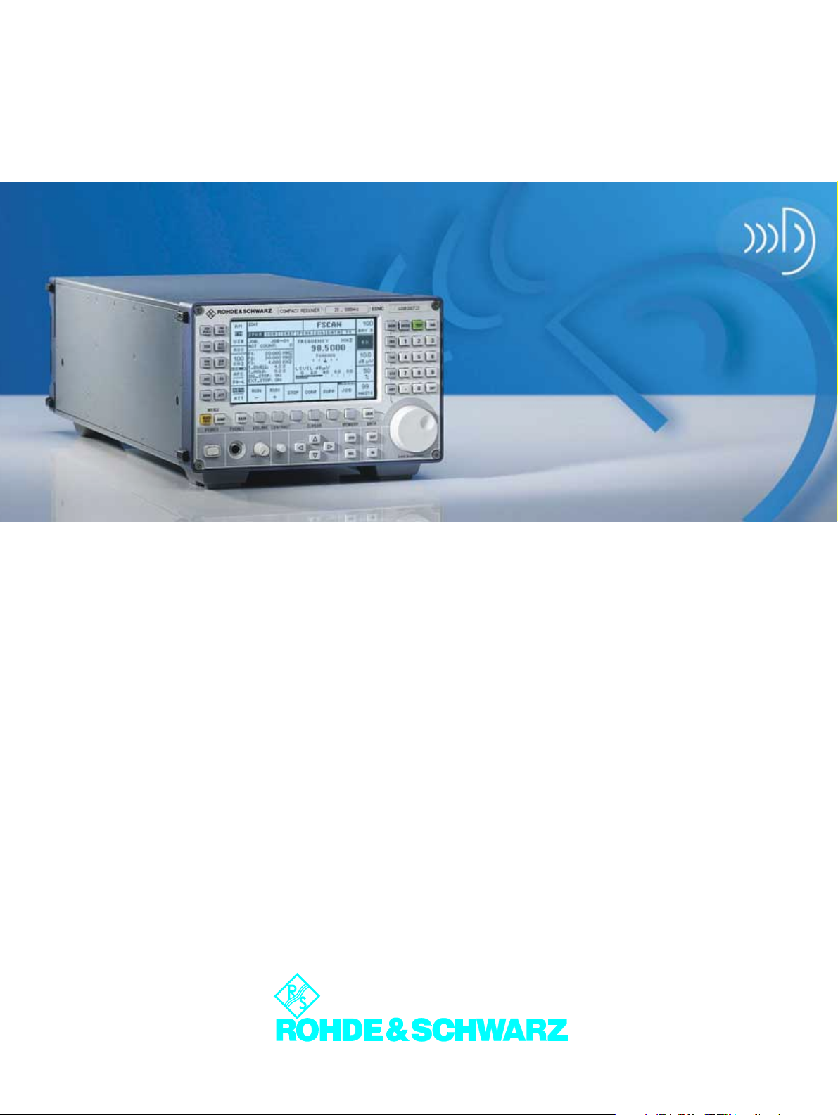
Compact Receiver ESMC
Lightweight – compact – user-friendly:
optimized radiomonitoring from 0.5 MHz to 3000 MHz
• Signal reception
– aural monitoring
– radiomonitoring
– recording
•1 Hz frequency resolution
• Searching and scanning
– continuous manual tuning
– at any channel spacing
– 5 start/stop frequency ranges
– spectrum display with a
speed of up to 13 GHz/s
– within 1000 memory locations
•Measurement of
– frequency occupancy
– level and frequency
– coverage
• RF and IF spectrum display
Page 2
With the Compact Receiver ESMC, a universal
and multipurpose receiver for radiomonitoring
applications has been
produced in a compact
size that was thought not
possible up to now.
The new receiver is only
half the size of customary
19" multipurpose receivers of 3 height units but its
technical data are even
superior to those of such
units.
The most important
features are:
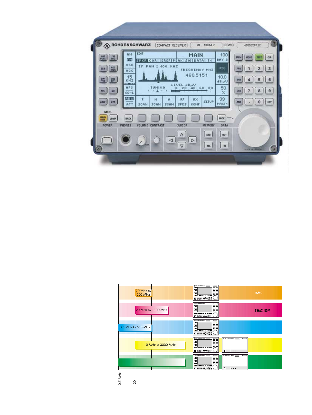
• custom-specific frequency extension
from HF to UHF (see diagram)
• detection of frequency-agile emissions with analog sweep
• compact design and low weight
• simple operation via LC display
• wide dynamic range and high
overload capacity
• 1 Hz frequency resolution
• low phase noise
• master/slave operation without a PC
• accurate measurement of signal level
• offset display for channel frequency
• remote control unit for mobile use
• AC/DC supply without changing
the power supply unit
Operation
The operating concept meets all the demands made on a state-of-the-art radiomonitoring receiver, ie all main functions such as type of demodulation,
bandwidth, etc, can be set directly via
labelled keys. A hotkey permits returning to the main menu from any submenu.
Menu control is organized in priority levels so that signal processing is not interrupted by menu changes and the user
never loses sight of what is going on.
Description
ESMC is a heterodyne receiver with a
second IF of 21.4 MHz. In spite of the
compact design, no compromises have
been made in the operating concept.
For reducing the total signal load, the
tuners are each provided with a tracking preselection filter. High-level mixers
Compact Receiver ESMC: radiomonitoring from 0.5 MHz to 3000 MHz
Frequency range Device view Basic configuration
20 MHz to
650 MHz
20 MHz to 1300 MHz
0.5 MHz to 650 MHz
20 MHz to 3000 MHz
0.5 MHz to 3000 MHz
20 MHz
0.5 MHz
650 MHz
1300 MHz
3000 MHz
ensure high immunity to intermodulation. The low oscillator reradiation is
the result of elaborate filtering. An advanced synthesizer concept featuring a
very low phase noise allows switching
times of less than 1 ms. This permits
highly efficient scanning and fast status
assignment in slave operation.
ROHDE& SCHWARZ
ROHDE& SCHWARZ
ROHDE& SCHWARZ
ROHDE& SCHWARZ ROHDE& SCHWARZ
ROHDE& SCHWARZ ROHDE& SCHWARZ
Configuration 0.5 MHz...1300 MHz on request
ESMC
ESMC
ESMC, ESMC-T2
ESMC, ESMC-T2
ESMC, ESMC-T0
ESMC, ESMC-T0
ESMC, ESMC-T2,
ESMC, ESMC-T2,
ESMC-FE
ESMC-FE
ESMC, ESMC-T2,
ESMC, ESMC-T2,
ESMC-FE, ESMC-T0,
ESMC-FE, ESMC-T0,
ESMC-TC
ESMC-TC
2 Compact Receiver ESMC
Page 3
ESMC is equipped with demodulators
for AM, FM, LOG and PULSE modes.
SSB reception for LSB/USB and A1 is
optional. The log demodulator allows a
dB-linear level indication over 9 decades. Average value or peak weighting
may be selected. The absolute accuracy
of the level display is further improved
by taking into account the frequency response of the preselection filter and the
tolerances of the log amplifier in the
measurement of the signal level.
ESMC may be equipped with up to 5 IF
bandwidths between 500 Hz and
8 MHz. Video filters matched to the
bandwidth used and a switchable AF
filter improve the S/N ratio after demodulation.
AGC covers a level range of 120 dB,
90 dB of which is used for IF control and
30 dB for an attenuator at the tuner input which may be switched in automatically or manually when strong signals
are received. This attenuator is considered in the level display. With manual
gain control (MGC) the IF gain may be
varied by 90 dB. The 30 dB attenuation
too may be switched in if required.
Frequency scan
Five start/stop frequency ranges (5
jobs) may be defined and a complete
data set allocated to each range. In addition to receiver settings, the following
scan parameters may be included in
the data set:
– step width
– signal threshold (dBµV)
– dwell time (s)
– hold time (ms) plus the time re-
quired for external devices,
if any
– number of scan repetitions
– signal-controlled continuation
(on/off)
– suppression (individual frequencies
or ranges)
Memory scan
ESMC uses 1000 memory locations,
each holding a complete receiver setting, such as frequency, type of modulation, bandwidth, etc. The content of
the memory can be modified manually
or overwritten by results of a scan operation. User-definable code names,
group ID and scan enable flags may
also be defined for each location. Final-
ly the whole memory can be sorted according to increasing frequency values. The content of any memory location can be transferred to the receiver
manually, by using the RCL key, by turning the tuning knob or automatically by
activating the memory scan.
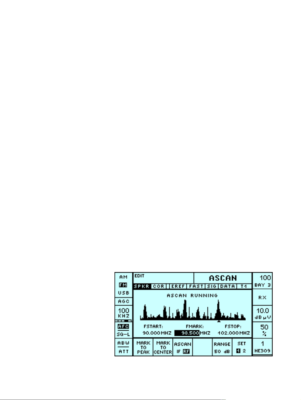
Analog scan – full-speed detection of
bursts and hoppers
The advantage of analog sweep is the
extremely high speed. This allows detection of burst signals and frequency-agile
transmissions. With the option
ESMC-AS and an external PC a program under Windows™ is provided,
which enables panoramic and waterfall
displays. Start and stop frequency are
freely selectable within any tuner range.
Depending on the performance of the
controlling PC, a scanning speed of up
to 13 GHz/s can be achieved. With
the aid of a printer, measurement results may be documented as a frequency-versus-time plot.
Click & listen
For fixed frequency monitoring a spectrum line can be selected by mouse click
or by frequency marker.
A tuning indication controlled by the
crystal discriminator simplifies tuning to
the center of the selected IF bandwidth.
When signals of unstable frequency
are received, digital AFC may be used
for retuning the receiver.
Search facilities
The ESMC uses highly advanced
search routines. Fast synthesizer settling and short level measurement times
guarantee highly effective search operations. The shortest period for scanning
is 5 ms with an IF bandwidth of 15 kHz
(incl. measurement time for level).
With option ESMC-AS fast hopping frequencies can be detected
Compact Receiver ESMC 3
Page 4

Real-time spectrum display
with EPZ513
The external Spectrum Display
EPZ 513 provides highly versatile display modes. An analog CRT guarantees display in real time.
RF mode 650 MHz within 50 ms
In this mode the tuner section of ESMC
is directly controlled by the EPZ513.
The period of the sweep is 50 ms, independent of the span.
The spectrum is displayed on the screen
within the tuner range. A superimposed
marker indicates the frequency to
which the receiver has been tuned.
With the aid of the start/stop frequency
markers entered on the ESMC, the span
may be expanded within a wide range.
The amplitude range covers 80 dB and
uses a selectable level line.
IF mode
In this mode the signal environment
around the receive frequency is displayed. The span may be varied continuously or in steps of 7/2/0.2 MHz. Selection of resolution filters is automatic. The
zoom capability of the EPZ is very useful
in practical applications since details of
the signal spectrum can be examined. In
the double-trace mode, the total span
(7 MHz) and any expanded section thereof may be displayed simultaneously.
The advantage of real-time spectrum
display is that a quick overview of the
receive range is obtained and unknown signal activities (bursts, frequency hopping) can be detected.
Interfaces
For system applications ESMC is provided with a number of important interfaces:
• IEC 625-2 (IEEE 488) for computer
operation (standard)
With VHF-UHF Direction Finder DDF190 and Spectrum Display EPZ513 the Compact Receiver ESMC
forms a convenient VHF-UHF monitoring system
• RS232C/RS422/RS485 for computer operation (option ESMC-R2)
• Outputs for antenna control (eg via
Antenna Selector GS 050) with
– antenna number and
– coded frequency information
• 21.4 MHz IF output, controlled
(50 Ω, BNC)
• 21.4 MHz IF output, uncontrolled
(50 Ω, BNC)
• 21.4 MHz connector for external
spectrum display (50 Ω, BNC)
• Video output, AM/FM/LOG,
DC-coupled (50 Ω, BNC)
• DC connector for battery supply
• Connector for external bidirectional
reference frequency, 10 MHz (BNC)
• Output for 1st LO (50 Ω, BNC)
• Output for 2nd LO (50 Ω, BNC)
• AF balanced, 600 Ω
• AF unbalanced via AF filter
• 4 Ω output for external loudspeaker
• Carrier-operated relay (COR)
• Output for signal > threshold
• Output for log signal level
• Internal/external control
• Input for control voltage (MGC)
• Output for channel offset
• Others (special function ports)
Options
Several “plug&play“ options allow the
user to tailor the ESMC to his special
needs:
ESMC-T2 for frequency extension
up to 1.3 GHz
ESMC-T0 for frequency extension
from 0.5 MHz to 30 MHz
instead of ESMC-T2 or for
installation in ESMC-FE.
(Max. IF bandwidth =
30 kHz).
4 Compact Receiver ESMC
Page 5

ESMC-FE separate 1/219“ unit for
ESMC-GB remote control unit (opera-
frequency extension from
1.3 GHz to 3 GHz or
0.5 MHz to 3 GHz
ESMC-AN antenna splitter for one
antenna input, 20 MHz to
ESMC-Z1 IF section with special
3 GHz (only with ESMC-FE)
ESMC-OR 10 MHz OCXO reference
5)
(error ≤0.1 x 10
ESMC-S3 for reception of
LSB/USB and A1
ESMC-SU low-cost panoramic
adapter using the LCD of
the receiver
ESMC-AS analog scan function
−6
)
All these options can be added to the
basic version of the ESMC without any
software reconfiguration; whenever a
module is changed or added, a recalibration process is started automatically
after power-up.
and software for use with
PC AT486 or Pentium
ESMC-R1 for remote control via
Designed to meet the standards
IEC625-2/IEEE 488
(instead of ESMC-R2)
ESMC-R2 for remote control via
RS232, RS422 and
RS485 bus (instead
of ESMC-R1)
The receiver has been designed for sta-
tionary and mobile use according to
DIN IEC721 recommendations for
class-C instruments. Careful shielding
and filtering of all input and output lines
ensures ultralow spurious emissions
and low EMS.
tor front panel) for controlling ESMC model .02 or
.03 via serial link espcially for mobile applications
bandwidth (see ordering
information)
Diagnostic center included
The receiver is permanently monitored
by built-in test (BIT). If deviations from
nominal values are detected, an error
message is output with a code informing on the type of fault. For detailed information, the values of 48 internal test
probes including upper and lower limits are available on the screen. Any values which are out of range will be highlighted on the display. In a loop test triggered by the user, the complete signal
path between the antenna input and the
loudspeaker or video output is checked
out. This test is carried out with an internally generated and modulated test signal of calibrated frequency.
User-friendly maintenance
The advanced design, based on plug-in
modules guarantees short MTTR. All
modules of the unit may be exchanged
without any recalibration or adjustments being required.
Remote control
All receiver functions can be remotecontrolled by a controller via the standard IEC 625-2 (IEEE 488) interface or
via the optional RS232C/RS422/
RS485 interface. If no acknowledgements for the settings are required, simplified master-slave operation will be
possible without the use of an additional controller. In this case the ESMC used
as a master (talker) may address up to
ten slave ESMCs (listeners) and transfer
the corresponding setups to the slaves.
The transferred setups are stored automatically in the master under the slave
addresses and may be read out (electronic notebook).
Model .02/.03 of ESMC for remote control or
for detached front panel ESMC-GB, eg for convenient use in cars
Compact Receiver ESMC 5
Page 6

ESMC-RAMON – access to
computer-aided radiomonitoring
Compact radiomonitoring system
With its favourable price, ESMCRAMON is an ideal compact radio
monitoring software. It is configured to
control one ESMC and can be expanded to set additional ESMC and
ESM500 slave receivers to perform radiomonitoring and radiosurveillance
tasks.
The system provides three operating
modes:
• Static mode: the receiver can be
tuned for monitoring
• Search mode: the receiver scans
frequency ranges and/or a frequency list and stops for a definable time at each signal activity
• Overview mode: the receiver
scans frequency ranges and/or a
frequency list continuously to display the frequency spectrum
The overview mode
shows active signals with their levels as
green lines. The duration of the signal
activity is displayed in a waterfall, with
the signal level being indicated in colour. Important parameters can be
measured using markers and rulers in
different colours.
ESMC-RAMON: Overview Mode
ESMC-RAMON-Evaluate
The ESMC-RAMON-Evaluate option
permits the recording of signal activities in the overview mode. Such recordings can be evaluated with the scan replay tool and analyzed in detail with
the activity analyzer.
ESMC-RAMON-MasterSlave
This option allows up to six ESMC receivers to be connected to the system via IEC/
IEEE bus. The slave receivers are set and
enabled automatically. A free slave receiver will be set to a frequency, which is
detected by the master receiver running
in the search mode. The slave receiver
will be enabled for new settings after the
signal is below a selectable threshold for
a selectable time. With this option, frequency bands and single frequencies
can be monitored automatically.
ESMC or ESM 500
IEC/IEEE bus
ESMC
ESMC-RAMON-Log
This option allows the logging of the
master receiver settings.
The settings can be stored in a log file. In
combination with the Log option or the
Master Slave option, all transfers to slave
receivers are also stored in the log file.
ESMC RAMON-IEEE488 Kit
This option contains the necessary
IEEE488 board for the control PC, the
board driver software, the driver installation manual and a 2 m IEEE488 cable
for connecting the ESMC.
Upgrading possibility
The close relationship to RAMON
®
makes upgrading to the full RAMON
software very easy. Existing equipment
can still be used. All that remains to be
done is to install the new software. As
the operational concept is similar, existing knowledge can be used. All this
shows that ESMC-RAMON is a Rohde
&Schwarz product providing easy access to computer-aided radiomonitoring.
6 Compact Receiver ESMC
System requirements
– IBM-compatible PC
– minimum 486/DX2-66, 8 MByte
RAM
– min. 10 MB hard disk space
– colour graphics adapter with min.
resolution 1024 x 768 pixels
– mouse or other pointing device
– Windows 3.1, Windows 95 or
Windows NT
Page 7

Specifications
Frequency range
Basic unit (with tuner 1) 20 MHz to 650 MHz
Tuner 0 0.5 MHz to 30 MHz (optional)
Tuner 2 650 MHz to 1300 MHz (optional)
ESMC-FE (Tuner 3) 1300 MHz to 3000 MHz (optional)
Frequency setting 1 kHz, 100 Hz, 10 Hz, 1 Hz
Frequency error
Frequency aging ≤±0.5 x 10⁻⁶ per year
Oscillator phase noise
for tuner 0
Synthesizer settling time
Antenna input s N connectors, 50
Oscillator reradiation
Tuner 0
Input selectivity tuned filters
Tuner 0 4 switched bandpass filters
≤±1.5 x 10
≤±0.1 x 10
≤−110 dBc (10 kHz)
≤−138 dBc (10 kHz)
≤1 ms
overload-protected
≤−107 dBm
≤−127 dBm
ESMC-FE (Tuner 3) 3 switched bandpass filters
Immunity to interference,
nonlinearities
Image frequency rejection , all tuners typ. 110 dB,
IF rejection, all tuners typ. 110 dB,
IP2
Tuner 1, tuner 2 typ. 50 dBm,
ESMC-FE (Tuner 3) typ. 43 dBm
Tuner 0 typ. 70 dBm,
IP3
Tuner 1 typ. 12 dBm,
Tuner 2, ESMC-FE (Tuner 3) typ. 10 dBm,
Tuner 0 typ. 35 dBm,
Spurious
Tuner 1, tuner 2, ESMC-FE
Tuner 3 )
Tuner 0
≤–107 dBm
≤–113 dBm
−6
(−10 °C to +55 °C)
–6
(Option ESMC-OR)
Ω, VSWR ≤2.5,
≥90 dB
≥90 dB
≥40 dBm
, ≥35 dBm
≥55 dBm
≥8 dBm
≥6 dBm
≥28 dBm
Sensitivity
Total noise figure (incl. AF section) typ. 10 dB,
(S+N)/N ratio measurement using telephone filter to
AM, B= 8 kHz, f
20 MHz to 650 MHz (tuner 1),
=−107 dBm (1 µV) ≥10 dB
V
in
650 MHz to 1300 MHz (tuner 2),
V
=−103.5 dBm (1.5 µV) ≥10 dB
in
=−47 dBm (1 mV) ≥47 dB
V
in
1300 MHz to 3000 MHz
(ESMC-FE, tuner 3)
=–103.5 dBm (1.5 µV) ≥10 dB
U
e
U
=–47 dBm ( 1 mV) ≥47 dB
e
FM, B=15 kHz, f
deviation 5 kHz
20 MHz to 650 MHz (tuner 1),
=−107 dBm (1 µV) ≥25 dB
V
in
650 MHz to 1300 MHz (tuner 2),
=−103.5 dBm (1.5 µV) ≥25 dB
V
in
V
=−47 dBm (1 mV) ≥70 dB
in
1300 MHz to 3000 MHz
(ESMC-FE, tuner 3)
=–103.5 dBm (1.5 µV) ≥25 dB
U
e
=–47 dBm ( 1 mV) ≥70 dB
U
e
USB/LSB, B= 2.5 kHz,
20 MHz to 650 MHz (tuner 1),
=−117 dBm (0.3 µV) ≥10 dB
V
in
V
=−47 dBm (1 mV) ≥50 dB
in
Tuner 0, (S+N)/N ratio
LSB/USB, IF bandwidth 500 Hz,
∆f=500 Hz
0.5 MHz to 20 MHz, V
20 to 30 MHz, V
LSB/USB, IF bandwidth 2.5 kHz,
∆f=1 kHz
0.5 MHz to 20 MHz, V
20 MHz to 30 MHz, V
=1 kHz, m=0.5
mod
=1 kHz,
mod
∆f=1 kHz
= 0.4 µV ≥10 dB
in
= 0.5 µV ≥10 dB
in
= 0.6 µV ≥10 dB
in
= 0.7 µV ≥10 dB
in
V
=100 µV ≥46 dB
in
(20 MHz to 650 MHz)
typ. 11 dB,
(650 MHz to 1300 MHz)
typ. 11 dB,
(1300 MHz to 2000 MHz)
typ. 12 dB,
(2000 MHz to 3000 MHz)
CCITT
≤13.5 dB
≤14.5 dB
≤13 dB
≤14.5 dB
7 Compact Receiver ESMC
Rear of ESMC; the IEC/IEEE
bus can optionally be replaced by RS232 and
RS422/RS 485 interface
Page 8

AM, IF bandwidth 2.5 kHz,
f
=1 kHz, m=0.5
mod
0.5 MHz to 20 MHz, V
20 MHz to 30 MHz, V
Large signal behaviour for tuner 0
Crossmodulation
interfering signal 2.5 V (+21 dBm),
∆f ≥ 30 kHz; m = 0.3; f = 1 kHz,
signal level 5 mV (
modulation transfer
Blocking
interf. signal 3.15 V (+ 23 dBm),
∆f ≥ 30 kHz,
signal level 500
m = 0.3, f = 1 kHz
signal attenuation
Desensitization
interf. signal 150 mV (
∆f ≥ 30 kHz,
signal level 15
bandwidth 2.5 kHz
SINAD
Demodulation AM, FM , LOG, PULSE;
Squelch signal-controlled, adjustable
AGC range 90 dB; 1
RF attenuator 30 dB (40 dB with tuner 0) selectable or
AGC speed for 90 dB range Attack Decay
Range of MGC (manual gain control) 90 dB
EGC (external gain control)
by analog voltage 90 dB
COR
Decay adjustable 1 s to 10 s
Attack
AFC digital tuning for signals of unstable fre-
Offset indication graphic using tuning markers,
Signal-level indication graphic as level line or numeric from
Resolution graphic 1 dB, numeric 0.1 dB
Error
Memory scan MSCAN 1000 definable memory locations,
Frequency scan FSCAN five definable start/stop frequency
Analog sweep ASCAN (option) full receive range (max. 650 MHz) or
Frequency marker added for receiver tuning
Sweep time approx. 47 ms
Resolution filter IF filters of receiver
Built-in test (BIT)
Continuous test module monitoring, test points of mod-
Loop test key-triggered, automatic test of com-
= 1 µV ≥10 dB
in
= 1.2 µV ≥10 dB
in
−33 dBm)
µV (−53 dBm),
−3.5 dBm),
µV (−83.5 dBm),
≤10 %
≤1 dB
≥20 dB
SSB and CW optional
−10 dBµV to 80 dBµV (max. 110 dBµV,
120 dB
µV with tuner 0)
µV to 10 mV makes ≤4 dB dif-
ference in AF level
signal-controlled
AM/B= 15 kHz <15 ms 15 ms
Pulse/B= 100 kHz <0.1 ms
SSB/B= 2.5 kHz <1 ms
3 s, corr. to
3dB/100ms
≤25 ms
quency
numeric in 50 Hz steps (B
≤100 kHz)
−10 dBµV to 80 dBµV (110 dBµV),
with tuner 0 120 dB
µV
≤±3 dB, ≤±2 dB for level ≥ 0 dBµV
each location may be allocated a complete set of receive data, up to 250 ch/s
spans with separate receive data sets
(5 jobs), up to 250 ch/s
any expanded section
ules can be shown on display, fault signalling with error code + text
plete receive section incl. AF section
Real-time display on
Spectrum Display EPZ 513
IF
RF full receive range (max. 650 MHz) or
Inputs and outputs
IF 21.4 MHz, controlled output 500 Hz to 8 MHz
IF 21.4 MHz, uncontrolled output 500 Hz to 8 MHz
21.4 MHz, wideband output
Video output, AM/FM/LOG 1/2 IF bandwidth, DC-coupled, BNC,
AF output, balanced 600
AF output,
filtered, unbalanced 0.3 kHz to 3.4 kHz, fixed, 1 V (rms)
AF output, unbalanced 1 V (rms)
AF loudspeaker output 4
(AF filter 0.3 kHz to 3.4 kHz
may be switched to any
AF output)
Output, log signal level 0 V to +5 V, Z
Output, channel offset −5 V to +5 V, Z
Input, ext. MGC voltage 0 V to 2 V, Zin = 10 kΩ
Output, 1st LO 50 Ω, SMA, −10 dBm
Output, 2nd LO 50
Bidirectional referencefrequency connector 10 MHz, BNC
Special function ports configurable for muting, ext. scan stop,
Output for controlling
antenna selectors BCD, TTL level (for frequency
Data interfaces IEC 625-2 (IEEE 488) (standard) or
1
)
±3.5 MHz, ±1 MHz, ±100 kHz or
zoom
any expanded section
2
Ω, −10 dBm
50
V
+ 12 dB
in
±4 MHz uncontrolled, BNC, 50 Ω,
V
+9 dB, for external spectrum display
in
50
Ω, 2 V (pp); for log 1 V
), BNC,
2
), BNC, 50 Ω,
Ω, 0 dBm
Ω, 500 mW
= 1 kΩ
out
Ω
= 1 k
out
Ω, SMA, −15 dBm
in: 0.1 V to 2 V, Z
out: 3 dBm, Z
= 50 Ω
out
= 500 Ω
in
etc
information)
RS232C/RS422/RS485 (option)
SCPI syntax
General data
Operating temperature range
Nominal temperature range 0
Storage temperature range
Humidity to IEC 68-2-30,
model .02/.03 max. 95%, cyclic test 25
model .22/.23 max. 80%, cyclic test 25
Shock to IEC 68-2-27 (MIL-STD-810D,
Vibration (sinewave) to IEC 68-2-6 (MIL-T-28800D),
Vibration (noise) to IEC 68-2-36, 10 Hz to 500 Hz,
EMC VDE 0875 (RFI suppression grade K)
Power supply AC 100/120/230/240 V,
DC 10 V to 32 V, reverse d polarity pro tec-
Power consumption AC
DC
Dimensions (W x H x D) 219 mm x 147 mm x 460 mm
Weig ht
model .02/.03 11.5 kg
−10 °C to +55 °C
°C to +50 °C
−40 °C to +70 °C
°C/55 °C
°C/40 °C
MIL-T-28800D), shock spectrum 45 Hz
to 2000 Hz, 40 g
5 Hz to 55 Hz, 0.15 mm amplitude
1.9 g (rms)
VDE 0871, MIL-STD-461 - CE 03,
MIL-STD-461 - RE 02
47 Hz to 440 Hz, overvoltage protec-
−12%/+10%,
tion to VDE 160
tion
≤100 VA
≤75 W
1
/2 19", 3 heig ht uni ts)
(
model .22/.23 12 kg
Compact Receiver ESMC 8
Page 9

Ordering information
Compact Receiver ESMC (VHF/UHF basic unit)
Model .22, with front-panel control 4030.2007.22
Model .02, without front-panel control 4030.2007.02
models .22/.02 including:
IEC625 (IEEE 488) interface ESMC-R1
IF Section (filters 2.5 kHz/8 kHz/
15 kHz/100 kHz/2 MHz) ESMC-Z1
Model .23, with front-panel control 4030.2007.23
Model .03, without front-panel control 4030.2007.03
basic models .23/.03 without
ESMC-R1 and ESMC-Z1
ESMC-RAMON
Options for all models
Tuner 0 for 0.5 MHz to 30 MHz ESMC-T0
Tuner 2 for 650 MHz to 1300 MHz ESMC-T2
(combination of tuner 0 and tuner 2
in one ESMC case not possible)
SSB Unit ESMC-S3 4037.5501.02
IF Spectrum Unit ESMC-SU 4037.5553.02
ESMC-RA 4037.6508.02
ESMC-RE 3013.4815.02
ESMC-RM 3013.4838.02
ESMC-RL 3013.4844.02
ESMC-RI 3013.4867.02
3
) 4039.9004.03
3
) 4037.5201.02
Analog Scan (software) ESMC-AS 4042.0404.02
IEC625 (IEEE 488) Interface ESMC-R1
Serial Interface (RS232/422/485) ESMC-R2
Remote Control Unit
for model .02/.03 ESMC-GB 4039.8508.02
Frequency Extension
1.3 GHz to 3 GHz
(separate
OCXO Reference ESMC-OR
1
/219“unit) ESMC-FE 4042.6002.02
4
) 4037.5401.02
4
) 4037.5453.02
5
) 4042.6902.02
Antenna Splitter ESMC-AN 4042.6702.02
Recommended extras
Spectrum Display EPZ513 4011.9500.04
(data sheet PD756.9451)
19 " Adapter ZZA-98 0827.4533.00
for
one or two ESMC
one ESMC and one EK890/895
one ESMC and one EPZ513
one ESMC and one ESMC-FE
1
) External unit.
2
) Depending on selected bandwidth (see table on this page).
3
) Only one of these options to be fitted in ESMC.
4
) Only one of these options to be fitted.
5
) Slot in option ESMC-FE available, otherweise in ESMC basic unit instead
of option ESMC-SU.
Certified Quality System
ISO 9001
DQS REG. NO 1954-04
Compact Receiver ESMC 9
Page 10

Option to choose for model .23/.03
IF Section (special bandwidths) ESMC-Z1 4037.5253.XX
500 Hz 2.5 kHz 8 kHz 15 kHz 30 kHz 50 kHz 100 kHz 200 kHz 500 kHz 1 MHz 2 MHz 4 MHz 8 MHz Model
● ● ● ● ●
● ● ● ● ●
●●●●●
●●●●●
● ● ● ● ●
● ● ● ● ●
●●●●●
●●● ● ●
● ● ● ● ●
● ● ● ● ●
●●● ● ●
●●●● ●
● ● ● ● ●
● ● ● ● ●
●●●● ●
●●● ● ●
● ● ● ● ●
● ● ● ● ●
●●●●●
●● ● ●●
● ● ● ● ●
● ● ● ● ●
●●● ●●
●● ●●●
● ● ● ● ●
● ● ● ● ●
●●●●●
●● ●● ●
● ● ● ● ●
● ● ● ● ●
●●●●●
●●●●●
● ● ● ● ●
● ● ● ● ●
.02
.03
.04
.05
.06
.07
.08
.09
.10
.11
.12
.13
.15
.16
.17
.18
.19
.20
.21
.22
.23
.24
.25
.26
.27
.29
.30
.31
.32
.33
.34
.35
.36
.37
Other combinations (5 out of 13) on request
The max. IF bandwidth of tunerT0 (0.5 MHz to 30 MHz) is 30 kHz.
Bandwidths >30 kHz cannot be used in this frequency range.
Data without tolerances: typical values Printed in Germany 10/00 (U bb)
⋅
Subject to change
⋅
ROHDE & SCHWARZ GmbH & Co. KG ⋅ Muehldorfstrasse 15 ⋅ 81671 Munich, Germany
P.O. B. 8014 69 ⋅ 81614 Munich, Germany ⋅ Telephone +4989 4129-0 ⋅ Fax +4989 4129-13247 ⋅ www.rohde-schwarz.com
Printed on chlorine-free paper
⋅
Compact Receiver ESMC
⋅
PD 757.1090.25
 Loading...