

Page 1
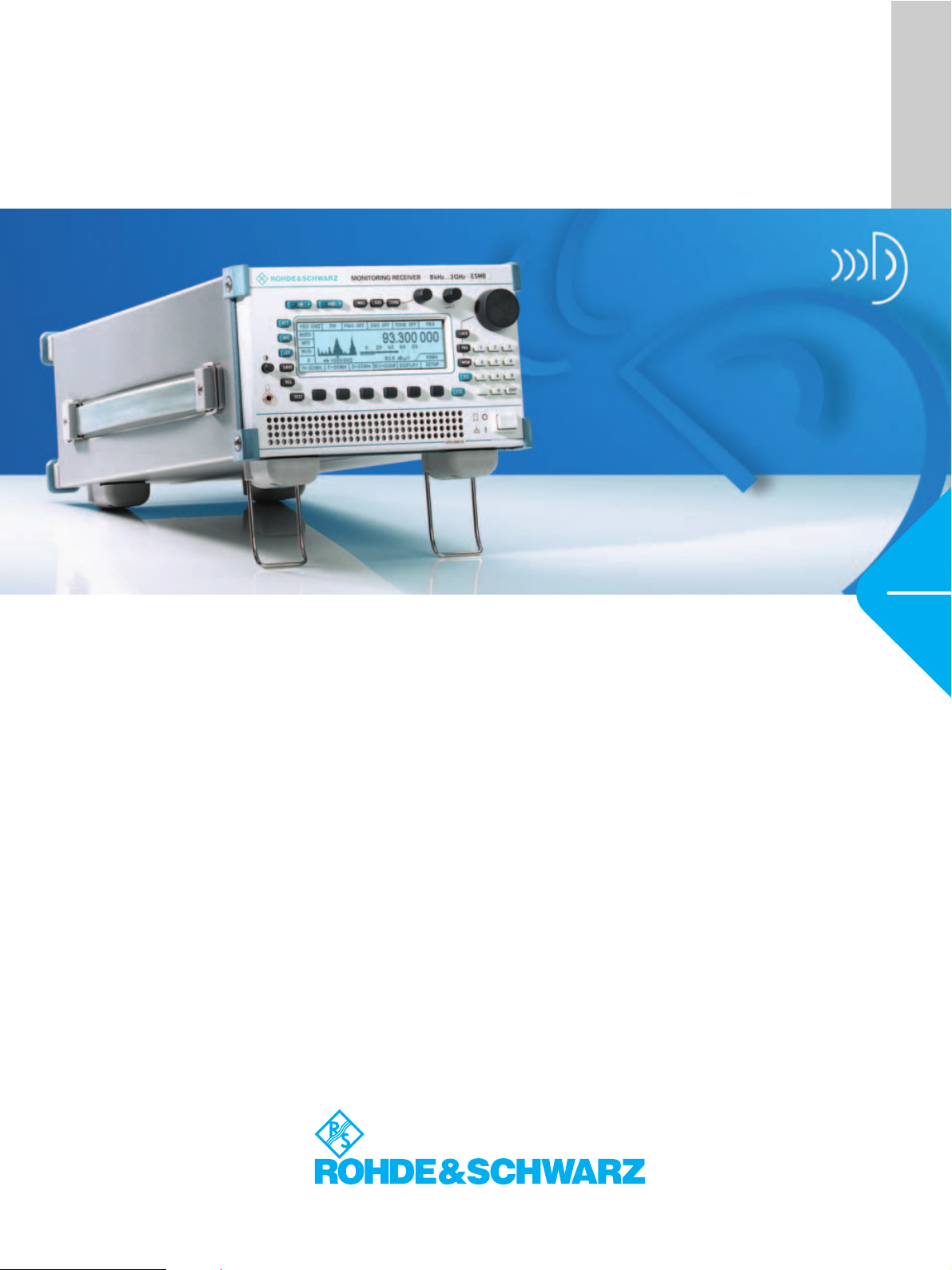
Monitoring Receiver R&S®ESMB
Data sheet
Version
03.00
September
2003
Military and civil monitoring from 9 kHz to 3 GHz
ITU-compliant measurements
The Monitoring Receiver R&S ESMB is
ideally suited for military monitoring tasks
and spectrum monitoring in line with ITU
recommendations as well as for use in
radio investigation services.
The range of applications includes:
◆ Signal detection
◆ Signal search in frequency and
memory scan mode
◆ Spectrum occupancy measurement
◆ RF and IF analysis
◆ Coverage measurements (option)
◆ Field-strength measurements
Page 2
General
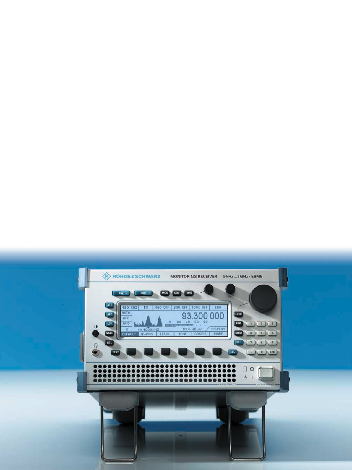
The R&S ESMB is a monitoring and test
receiver for all radio detection and
radiomonitoring
tasks in line with ITU-R,
and for radio investigation services. The
compact and sturdy design combined
with low weight makes the R&S ESMB a
versatile and universal unit for stationary
and mobile use.
Applications
The following measurements in line with
ITU-R specifications can be performed by
the R&S ESMB:
◆ Frequency and frequency offset to
ITU-R SM 377
◆ Field strength to ITU-R SM 378
◆ Modulation to ITU-R SM 328
◆ Spectrum occupancy and identifica-
tion with external PC to ITU-R SM 182
◆ Bandwidth to ITU-R SM 328
The optimized features of the R&S ESMB
allow fast performance of the following
additional tasks in military radiomonitoring and radio investigation services:
◆ Frequency scan with predefined
frequency ranges
◆ Memory scan of up to 1000 memory
channels
◆ RF frequency spectrum (option)
◆ Audio monitoring of CW, AM, SSB
and FM transmissions
◆ Identification
Description
As a ½ 19" unit, the R&S ESMB is ideal
both for mobile use and for rackmounting. It contains the following
functional units:
◆ A/D and DSP module with digital IF
filters, digital demodulators for CW,
AM, LSB, USB, PULSE, FM, PM, IQ
and ISB, parameter measurements
and FFT processing of IF panoramic
display
◆ Band and tracking preselection
◆ RF frontends for converting the
antenna signal into an IF of 10.7 MHz
◆ Fast synthesizer
◆ Processor system
◆ Display and control unit
◆ Remote control interface
◆ DC/DC converter
Digital IF section
The R&S ESMB covers a frequency range
from 9 kHz to 3 GHz. A large number of IF
bandwidths is required to process the various signals with optimum signal-to-noise
ratio. Maximum quality in a minimum of
space can only be ensured by using ultramodern digital signal processing throughout.
The R&S ESMB is equipped with 18 IF
filters from 150 Hz to 300 kHz, and up to
1 MHz in the IF panoramic mode.
2 Monitoring Receiver R&S
®
ESMB
Page 3
Operation
The Monitoring Receiver R&S ESMB
features full remote control capability as
well as manual control via the front panel.
The operating concept meets all the
demands made on a state-of-the-art
spectrum monitoring receiver, i.e. all the
main functions such as type of modulation, bandwidth, etc can easily be set
directly via labelled keys.
Menu control is organized in priority
levels so that signal processing is not
interrupted by menu changes and the
user has an optimized view of current
operations.
In conjunction with the
Digital Direction Finder
R&S DDF190, the
Monitoring Receiver
R&S ESMB forms a
monitoring system with
excellent price/performance ratio
◆ Step width
◆ Signal threshold (dBµV)
◆ Dwell time
◆ Hold time
◆ Number of scans
◆ Signal-controlled continuation
◆ Suppression (individual frequencies
or search ranges)
Memory scan
The R&S ESMB uses 1000 definable
memory locations. A complete data set
such as frequency, mode of demodulation, bandw
idth, squelch level, etc can be
assigned to each memory location. The
content of any memory location can be
transferred to the receiver manually using
the RCL key.
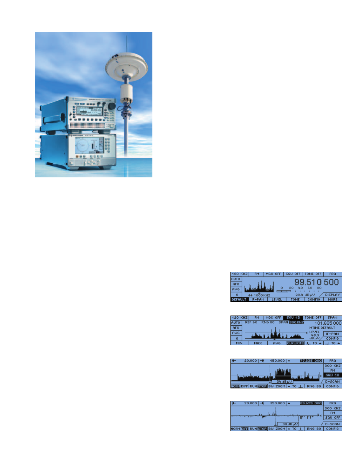
Emissions detected can be seen at a
glance. Aural monitoring of the information is possible by simply pressing a softkey. The R&S ESMB then goes to the DIGI
Scan listen mode. The stored spectrum is
displayed in the background, and the
emission of interest can be selected and
monitored by marking it with the
frequency cursor.
Location of miniature transmitters at
close range is possible in the differential
mode of the DIGI Scan option. In this
mode, the displayed spectrum is stored as
a reference. Current spectra are superimposed on the reference spectrum, and
any new signals or variations in signal
strength are clearly discernible as peaks.
If the measurement is carried out while
walking across the room, the field
strength of transmitters at close range
varies to a greater extent than that of
transmitters located far away. This differential display ensures fast and reliable location of miniature transmitters even in the
case of spread-spectrum transmission.
Optimized view for current task
Overview
IF panoramic display
Scan modes
Frequency scan
It is possible to define a frequency range
to which a complete data set can be allocated. In addition to receiver settings, the
following scan parameters are included in
the data set:
Frequency spectrum
Fitted with the frequency spectrum
option DIGI Scan, the R&S ESMB scans
the frequency range of interest with
digital control and displays the associated spectrum.
DIGI Scan listen mode
DIGI Scan differential mode
Monitoring Receiver R&S® ESMB 3
Page 4

g
R&S ESMB
in measurement mode
Bandwidth measurement
Interfaces
For system applications, the receiver is
equipped with a number of important
interfaces:
device functions as well as data output, but
also transmission of the digital AF. With the
aid of the DIGI Scan option, data for 20 000
channels/s can be output in the scan mode.
Modulation measurement
When equipped with the R&S EB200CM
option, the R&S ESMB can also be used
for coverage measurements. In this configuration, it is possible to perform up to
2000 triggered level measurements on
one frequency or up to 200 multichannel
measurements (with any frequency hopping). This option is only available via the
remote-control interface.
The R&S ESMB together with the R&S
ROMES software form a coverage
measurement system with excellent
price/performance ratio.
◆ Baseband output (digital)
◆ AF output (digital)
◆ IF 10.7 MHz ±2.5 MHz, VHF/UHF
IF 10.7 MHz ±5 kHz, HF
uncontrolled for external panoramic
display
◆ AF balanced 600 Ω, 0 dBm
◆ Output for external loudspeaker,
4 Ω, 500 mW
◆ Headphone socket via volume control
◆ Output for antenna control with
antenna number
◆ Connector for internal/external
reference frequency, 10 MHz
Remote-control interface
LAN TCP/IP (Ethernet 10Base-T), optional
9-pin RS-232-C. The LAN interface
(Ethernet 10Base-T) with TCP/IP protocol
fitted as standard enables the R&S ESMB
to be integrated into systems of varying
complexity. The high data rate of this
interface not
RF
antenna
input
VHF/
UHF
antenna
input
only allows full control of all
Preselection RF
– Band filter
– Switchable attenuator
– Preamplifier
Preselection VHF/UHF
– Tracking filter
– Band filter
– Switchable
attenuator/preamplifier
Frontend RF
– Mixer
– IF amplifier
Frontend VHF/UHF
– Mixer
– IF amplifier
– Oscillators
– Synthesizers
Designed to meet the standards
State-of-the-art design
The receiver is designed for both mobile
and stationary operation. Careful screening and filters in all the input and output
lines ensure extremely low spurious emissions and high interference rejection.
BITE
The receiver is permanently monitored by
built-in test equipment (BITE). If deviations from the nominal specifications are
detected, an error message is output with
a code indicating the type of error.
Serviceability
Modern design and the use of plug-in
modules ensure short repair times. All the
modules can be replaced without any
recalibration or adjustments being
required.
IF
Digital
IF panorama
Digital
IF processing
– 2 switchable prefilters
– A/D converter
– Coprocessor (DDC)
– Digital signal processor
– FFT calculation
– Demodulation
– Signal analysis
nal measurement
– Si
IF
AF
digital
AF
Front panel
– Display
– Controls
– Keys
– Rollkey
Data and control bus
RF, IF, AF analog
4 Monitoring Receiver R&S
®
ESMB
Control processor
– PC
– Firmware
Remote
Remote interface
– LAN (TCP/IP) or
RS-232-C
DC/DC converter
Block diagram of the Monitoring Receiver R&S ESMB
control
Power
supply
Page 5

Bandwidth and
modulation
measurements
with panoramic
display
Use in computer-controlled
systems
Full use of the performance features of
the receiver can be made in the remotecontrol mode via LAN using a suitable
PC and the Spectrum Monitoring
Software R&S ARGUS or R&S RAMON.
R&S RAMON, which is primarily used in
military and security applications,
enables fast frequency detection and
transfer to support monitoring receivers
(concentration on interactive operation
and signal identification).
R&S ARGUS is intended for applications
focusing on measurements, and is therefore particularly suitable for frequency
management tasks.
For basic tasks, the R&S ARGUS MON
software is available for remote control of
the R&S ESMB. The functionality of this
software, which features a favourable
price/performance ratio, is optimally tailored to the capabilities of the R&S ESMB.
It allows remote control of all settings,
measurement and scan functions as well
as saving of mea
quency, level, offset,
sured data such as fre-
date and time. The
basic R&S ARGUS MON software can be
Scan with 3D waterfall diagram
upgraded to R&S ARGUS for use in more
complex systems. The pictures above
show how easy-to-use and user-friendly
R&S ARGUS MON is. The R&S ESMB
together with R&S ARGUS MON is a costefficient basic system that fulfills all the
ITU recommendations.
Detailed information is provided in the
data sheet (PD0757.4818).
Monitoring Receiver R&S® ESMB 5
Page 6

Specifications
Frequency range
Base unit 20 MHz to 3 GHz
Base unit with
HF Option R&S ESMBHF
9 kHz to 3 GHz
Frequency setting
via keypad or rollkey
1 kHz, 100 Hz, 10 Hz, 1 Hz;
or in selectable increments
Frequency accuracy ≤0.5 × 10
–6
Input for external reference 10 MHz
Synthesizer setting time ≤3 ms, typ. 1 ms
Oscillator phase noise ≤–120 dBc (1 Hz) at 10 kHz offset (HF range)
≤–100 dBc (1 Hz) at 10 kHz offset
(VHF/UHF range)
Antenna inputs N socket, 50 Ω
VSWR ≤3, typ. 1.5 for HF range
≤2.5, typ. 1.8 for VHF/UHF range
Oscillator reradiation ≤–107 dBm
Input selection
9 kHz to 30 MHz
20 (30) MHz to 1500 MHz
1500 MHz to 3000 MHz
5 bandpass filters
tracking preselection
highpass, lowpass
Interference rejection, nonlinearities – HF range (only with HF Option
R&S ESMBHF)
Image frequency rejection ≥90 dB, typ. 100 dB
IF rejection ≥90 dB, typ. 100 dB
2nd order intercept point ≥50 dBm, typ. 60 dBm (ATT off)
3rd order intercept point1)≥20 dBm, typ. 25 dBm (ATT off)
Internal spurious signals ≤–107 dBm
Interference rejection, nonlinearities – VHF/UHF range
Image frequency rejection ≥80 dB, typ. 95 dB
IF rejection ≥90 dB, typ. 100 dB
2nd order intercept point ≥40 dBm, typ. 55 dBm (low distortion mode)
3rd order intercept point2)≥12 dBm, typ. 18 dBm (low distortion mode)
Internal spurious signals ≤–107 dBm
Sensitivity – HF range (only with HF Option R&S ESMBHF)
Overall noise figure
(including AF section)
≤14 dB, typ. 10 dB (f ≥50 kHz, ATT off),
0.1 MHz to 30 MHz
Signal-to-noise ratio measurement with telephone filter
CW, bandwidth 300 Hz,
V = 0.6 µV
≥10 dB
SSB, bandwidth 2.5 kHz
V = 1 µV
≥10 dB
AM, bandwidth 9 kHz
f
= 1 kHz, m = 0.5
mod
V = 1 µV
≥10 dB
Sensitivity – VHF/UHF range
Overall noise figure
(including AF section)
≤12 dB, typ. 9 dB,
20 (30) MHz to 2700 MHz (low noise mode)
Signal-to-noise ratio measurement with telephone filter
AM, bandwidth 9 kHz,
f
= 1 kHz, m = 0.5
mod
20 (30) MHz to 2700 MHz,
V = 1 µV
2.7 GHz to 3 GHz,
V = 1.3 µV
≥10 dB (low noise mode), typ. 16 dB
FM, bandwidth 15 kHz
f
= 1 kHz,
mod
deviation = 5 kHz
20 (30) MHz to 2700 MHz,
V = 1 µV
2.7 GHz to 3 GHz,
V = 1.3 µV
≥25 dB (low noise mode), typ. 30 dB
Detection modes AM, FM, PM, USB, LSB, CW, ISB, PULSE, IQ
IF bandwidths for
level detection and
offset measurement
23 filters (150 Hz to 1 MHz)
IF bandwidths with
standard demodulation
(–6 dB bandwidth)
0.15, 0.3, 0.6, 1, 1.5, 2.4, 3, 4, 6, 8, 9, 15, 30, 100,
120, 150, 250, 300 kHz
(reduced IF bandwidth in HF range: ±5 kHz)
Squelch, signal-controlled –30 dBµV to 110 dBµV
Gain control AGC, MGC (120 dB)
AFC digital retuning for unstable signals
Modulation measurement
AM (f
= 100 kHz)
max
Indication error
FM (f
= 100 kHz) deviation max. 125 kHz less modulation
max
m = 1% to 99% (resolution 0.1 %)
<5% for m = 50%, S/N >40 dB, AF = 1 kHz
frequency (resolution 0.001 kHz)
Indication error
Narrow bandwidths
(≤15 kHz)
100 Hz plus 3% of reading
Broad bandwidths
(≤250 kHz)
2 kHz plus 3% of reading for
S/N >40 dB, AF = 1 kHz
PM (f = 0.3 kHz to 5 kHz) ∆ϕ = 0 to 4π
∆ϕ = 0 to 12.5 rad (resolution 0.01 rad)
Indication error <0.1 rad plus 5% of reading for
S/N >40 dB, AF = 1 kHz
1)
Frequency spacing between intermodulating signals ≥30 kHz.
2)
Frequency spacing between intermodulating signals ≥2.2 MHz.
6 Monitoring Receiver R&S
®
ESMB
Page 7

Level and offset measurement
Offset indication graphically with tuning markers or numerically
Signal level –30 dBµV to 110 dBµV
Frequency scan start/stop/step and 100 suppress ranges,
typ. 250 channels/s (300 kHz IF filter)
DIGI Scan (option) RF spectrum with user-selectable start/stop
frequency, typ. 3000 MHz/s (300 kHz IF filter)
Error ≤±1.5 dB
typ. ±0.8 dB (HF range)
typ. ±1.0 dB (VHF/UHF range)
for V = 20 dBµV to 100 dBµV, AVG, 0°C to 45°C
Display numeric, 3 digits, resolution 0.1 dB or
graphic as level line
acoustic indication by level tone
Level indication mode AVG, PEAK, FAST, RMS
Field strength (dBµV/m) level range depending on antenna used
Display numeric
IF panoramic display internal module
Span range 0.15 kHz to 1000 kHz (23 steps)
Scan characteristics
Automatic memory scan 1000 definable memory locations,
typ. 200 channels/s (300 kHz IF filter)
Inputs/outputs
Reference frequency
connector
10 MHz, SMA, bidirectional
IF 10.7 MHz, wideband ±2.5 MHz (VHF/UHF range), ±5 kHz (HF range),
uncontrolled for external panoramic display,
SMA
Baseband output (digital) serial, 2 × 16 bit (clock, data, frame)
AF output (digital) AF signal, 2 × 16 bit, AES/EBU to
AES3-1985 (ANSI S4.40-1985)
AF output, balanced 600 Ω, 0 dBm
Loudspeaker output 4 Ω, 500 mW
Headphone output via volume control
BITE monitoring of test signals by means of loop test
Data interface LAN (Ethernet 10Base-T) or 9-pin RS-232-C, PPP
Rear view of the R&S ESMB
Monitoring Receiver R&S® ESMB 7
Page 8

General data
Ordering information
Rated temperature range 0°C to +50°C
Operating temperature range –10°C to +55°C
Storage temperature range –40°C to +70°C
Humidity max. 80%, cyclic test 25°C/55°C
max. 95% without condensation
Shock DIN IEC 60068-2-27 (MIL-STD-810E,
MIL-T-28800D), 40 g, spectrum 45 Hz to 2 kHz
Vibration (sinusoidal) DIN IEC 60068-2-6 (MIL-T-28800D),
5 Hz to 55 Hz, 0.15 mm amplitude,
55 Hz to 150 Hz, 0.5 g
Vibration (random) DIN IEC 60068-2-64, 10 Hz to 500 Hz, 1.9 g rms
EMC DIN EN 61000-6-3, 61000-6-4
Power supply 10 V to 32 V DC (max. 40 W) or
100 V to 240 V, 50 Hz to 60 Hz
via external AC/DC power supply
Dimensions (W × H × D) 227 mm × 153 mm × 474 mm
Rack model (½ 19" × 3 HU) 210 mm × 132 mm × 460 mm
Weight 8 kg
Order Designation Typ e Order No.
Monitoring Receiver
(with external power supply)
R&S ESMB 4056.6000.02
HF Option 9 kHz to 30 MHz R&S ESMBHF 4056.6100.02
Coverage Measurement Option R&S EB200CM 4052.9804.02
Frequency Spectrum Option
DIGI Scan
R&S ESMBDS 4056.6200.02
RS-232-C Serial Interface R&S ESMBR2 4052.9056.02
Software
R&S ARGUS basic module 3027.7363.0x
R&S ARGUS device driver for R&S ESMB 3027.7363.45
R&S RAMON basic module RA/BASIC 3020.9490.0x
R&S RAMON device driver EMB/CTL 3020.8264.02
Printed in Germany (U sk)
More information at
www.rohde-schwarz.com
(search term: ESMB)
Rohde& Schwarz GmbH&Co. KG ⋅ Mühldorfstraße 15 ⋅ 81671 München ⋅ Germany
P.O.B. 8014 69 ⋅ 81614 München ⋅ Germany ⋅ Telephone +49 89 41 29-0 ⋅ Fax +49 89 4129-132 47 ⋅ www.rohde-schwarz.com
ESMB ⋅ Version 03.00 ⋅ September 2003 ⋅ Data without tolerance limits is not binding ⋅ Subject to change
®
R&S® is a registered trademark of Rohde &Schwarz GmbH& Co. KG · Trade names are trademarks of the owners
PD 0758.0716.32 ⋅ Monitoring Receiver R&S
 Loading...