

Page 1

1166.6004.12-01 I-1 05/04
Operating Manual
EMI Test Receiver
R&S
ESCI
1166.5950.03
This manual consists of 2 volumes:
Volume 1
Printed in the Federal
Republic of Germany
Test and Measurement Division
Page 2

1166.6004.12-01 I-2 05/04
Dear Customer,
R&S® is a registered trademark of Rohde & Schwarz GmbH & Co. KG
Trade names are trademarks of the owners.
Page 3

R&S ESCI Tabbed Divider Overview
1166.6004.12 RE E-1
Tabbed Divider Overview
Volume 1 - Operating Manual - Manual Control
Data Sheet
Safety Instructions
Certificate of Quality
EU Certificate of Conformity
Support Center Address
List of R&S Representatives
Manuals for Test Receiver R&S ESCI
Tabbed Divider
1 Chapter 1: Putting into Operation
2 Chapter 2: Getting Started
3 Chapter 3: Operation
4 Chapter 4: Functional Description
5 Index
Volume 2 - Operating Manual - Remote Control
Safety Instructions
Tabbed Divider
5 Chapter 5: Remote Control – Basics
6 Chapter 6: Remote Control – Commands
7 Chapter 7: Remote Control – Program Examples
8 Chapter 8: Maintenance and Hardware Interfaces
9 Chapter 9: Error Messages
10 Index
Page 4

Page 5

1171.0000.42-02.00 Sheet 1
Before putting the product into operation for
the first time, make sure to read the following
Safety Instructions
Rohde & Schwarz makes every effort to keep the safety standard of its products up to date and to offer
its customers the highest possible degree of safety. Our products and the auxiliary equipment required
for them are designed and tested in accordance with the relevant safety standards. Compliance with
these standards is continuously monitored by our quality assurance system. This product has been
designed and tested in accordance with the EC Certificate of Conformity and has left the manufacturer’s
plant in a condition fully complying with safety standards. To maintain this condition and to ensure safe
operation, observe all instructions and warnings provided in this manual. If you have any questions
regarding these safety instructions, Rohde & Schwarz will be happy to answer them.
Furthermore, it is your responsibility to use the product in an appropriate manner. This product is
designed for use solely in industrial and laboratory environments or in the field and must not be used in
any way that may cause personal injury or property damage. You are responsible if the product is used
for an intention other than its designated purpose or in disregard of the manufacturer's instructions. The
manufacturer shall assume no responsibility for such use of the product.
The product is used for its designated purpose if it is used in accordance with its operating manual and
within its performance limits (see data sheet, documentation, the following safety instructions). Using
the products requires technical skills and knowledge of English. It is therefore essential that the
products be used exclusively by skilled and specialized staff or thoroughly trained personnel with the
required skills. If personal safety gear is required for using Rohde & Schwarz products, this will be
indicated at the appropriate place in the product documentation.
Symbols and safety labels
Observe
operating
instructions
Weight
indication for
units >18 kg
Danger of
electric
shock
Warning!
Hot
surface
PE terminal Ground
Ground
terminal
Attention!
Electrostatic
sensitive
devices
Supply
voltage
ON/OFF
Standby
indication
Direct
current
(DC)
Alternating
current (AC)
Direct/alternating
current (DC/AC)
Device fully
protected by
double/reinforced
insulation
Page 6

Safety Instructions
1171.0000.42-02.00 Sheet 2
Observing the safety instructions will help prevent personal injury or damage of any kind caused by
dangerous situations. Therefore, carefully read through and adhere to the following safety instructions
before putting the product into operation. It is also absolutely essential to observe the additional safety
instructions on personal safety that appear in other parts of the documentation. In these safety
instructions, the word "product" refers to all merchandise sold and distributed by Rohde & Schwarz,
including instruments, systems and all accessories.
Tags and their meaning
DANGER
This tag indicates a safety hazard with a high potential of risk for the
user that can result in death or serious injuries.
WARNING
This tag indicates a safety hazard with a medium potential of risk for the
user that can result in death or serious injuries.
CAUTION This tag indicates a safety hazard with a low potential of risk for the user
that can result in slight or minor injuries.
ATTENTION
This tag indicates the possibility of incorrect use that can cause damage
to the product.
NOTE
This tag indicates a situation where the user should pay special attention
to operating the product but which does not lead to damage.
These tags are in accordance with the standard definition for civil applications in the European
Economic Area. Definitions that deviate from the standard definition may also exist. It is therefore
essential to make sure that the tags described here are always used only in connection with the
associated documentation and the associated product. The use of tags in connection with unassociated
products or unassociated documentation can result in misinterpretations and thus contribute to personal
injury or material damage.
Basic safety instructions
1. The product may be operated only under
the operating conditions and in the
positions specified by the manufacturer. Its
ventilation must not be obstructed during
operation. Unless otherwise specified, the
following requirements apply to
Rohde & Schwarz products:
prescribed operating position is always with
the housing floor facing down, IP protection
2X, pollution severity 2, overvoltage
category 2, use only in enclosed spaces,
max. operation altitude max. 2000 m.
Unless specified otherwise in the data
sheet, a tolerance of ±10% shall apply to
the nominal voltage and of ±5% to the
nominal frequency.
2. Applicable local or national safety
regulations and rules for the prevention of
accidents must be observed in all work
performed. The product may be opened
only by authorized, specially trained
personnel. Prior to performing any work on
the product or opening the product, the
product must be disconnected from the
supply network. Any adjustments,
replacements of parts, maintenance or
repair must be carried out only by technical
personnel authorized by Rohde & Schwarz.
Only original parts may be used for
replacing parts relevant to safety (e.g.
power switches, power transformers,
fuses). A safety test must always be
performed after parts relevant to safety
have been replaced (visual inspection, PE
conductor test, insulation resistance
measurement, leakage current
measurement, functional test).
3. As with all industrially manufactured goods,
the use of substances that induce an
allergic reaction (allergens, e.g. nickel)
such as aluminum cannot be generally
excluded. If you develop an allergic
reaction (such as a skin rash, frequent
sneezing, red eyes or respiratory
difficulties), consult a physician immediately
to determine the cause.
Page 7

Safety Instructions
1171.0000.42-02.00 Sheet 3
4. If products/components are mechanically
and/or thermically processed in a manner
that goes beyond their intended use,
hazardous substances (heavy-metal dust
such as lead, beryllium, nickel) may be
released. For this reason, the product may
only be disassembled, e.g. for disposal
purposes, by specially trained personnel.
Improper disassembly may be hazardous to
your health. National waste disposal
regulations must be observed.
5. If handling the product yields hazardous
substances or fuels that must be disposed
of in a special way, e.g. coolants or engine
oils that must be replenished regularly, the
safety instructions of the manufacturer of
the hazardous substances or fuels and the
applicable regional waste disposal
regulations must be observed. Also
observe the relevant safety instructions in
the product documentation.
6. Depending on the function, certain products
such as RF radio equipment can produce
an elevated level of electromagnetic
radiation. Considering that unborn life
requires increased protection, pregnant
women should be protected by appropriate
measures. Persons with pacemakers may
also be endangered by electromagnetic
radiation. The employer is required to
assess workplaces where there is a special
risk of exposure to radiation and, if
necessary, take measures to avert the
danger.
7. Operating the products requires special
training and intense concentration. Make
certain that persons who use the products
are physically, mentally and emotionally fit
enough to handle operating the products;
otherwise injuries or material damage may
occur. It is the responsibility of the
employer to select suitable personnel for
operating the products.
8. Prior to switching on the product, it must be
ensured that the nominal voltage setting on
the product matches the nominal voltage of
the AC supply network. If a different voltage
is to be set, the power fuse of the product
may have to be changed accordingly.
9. In the case of products of safety class I with
movable power cord and connector,
operation is permitted only on sockets with
earthing contact and protective earth
connection.
10. Intentionally breaking the protective earth
connection either in the feed line or in the
product itself is not permitted. Doing so can
result in the danger of an electric shock
from the product. If extension cords or
connector strips are implemented, they
must be checked on a regular basis to
ensure that they are safe to use.
11. If the product has no power switch for
disconnection from the AC supply, the plug
of the connecting cable is regarded as the
disconnecting device. In such cases, it
must be ensured that the power plug is
easily reachable and accessible at all times
(length of connecting cable approx. 2 m).
Functional or electronic switches are not
suitable for providing disconnection from
the AC supply. If products without power
switches are integrated in racks or systems,
a disconnecting device must be provided at
the system level.
12. Never use the product if the power cable is
damaged. By taking appropriate safety
measures and carefully laying the power
cable, ensure that the cable cannot be
damaged and that no one can be hurt by
e.g. tripping over the cable or suffering an
electric shock.
13. The product may be operated only from
TN/TT supply networks fused with max.
16 A.
14. Do not insert the plug into sockets that are
dusty or dirty. Insert the plug firmly and all
the way into the socket. Otherwise this can
result in sparks, fire and/or injuries.
15. Do not overload any sockets, extension
cords or connector strips; doing so can
cause fire or electric shocks.
16. For measurements in circuits with voltages
V
rms
> 30 V, suitable measures (e.g.
appropriate measuring equipment, fusing,
current limiting, electrical separation,
insulation) should be taken to avoid any
hazards.
17. Ensure that the connections with
information technology equipment comply
with IEC 950/EN 60950.
18. Never remove the cover or part of the
housing while you are operating the
product. This will expose circuits and
components and can lead to injuries, fire or
damage to the product.
Page 8

Safety Instructions
1171.0000.42-02.00 Sheet 4
19. If a product is to be permanently installed,
the connection between the PE terminal on
site and the product's PE conductor must
be made first before any other connection
is made. The product may be installed and
connected only by a skilled electrician.
20. For permanently installed equipment
without built-in fuses, circuit breakers or
similar protective devices, the supply circuit
must be fused in such a way that suitable
protection is provided for users and
products.
21. Do not insert any objects into the openings
in the housing that are not designed for this
purpose. Never pour any liquids onto or into
the housing. This can cause short circuits
inside the product and/or electric shocks,
fire or injuries.
22. Use suitable overvoltage protection to
ensure that no overvoltage (such as that
caused by a thunderstorm) can reach the
product. Otherwise the operating personnel
will be endangered by electric shocks.
23. Rohde & Schwarz products are not
protected against penetration of water,
unless otherwise specified (see also safety
instruction 1.). If this is not taken into
account, there exists the danger of electric
shock or damage to the product, which can
also lead to personal injury.
24. Never use the product under conditions in
which condensation has formed or can form
in or on the product, e.g. if the product was
moved from a cold to a warm environment.
25. Do not close any slots or openings on the
product, since they are necessary for
ventilation and prevent the product from
overheating. Do not place the product on
soft surfaces such as sofas or rugs or
inside a closed housing, unless this is well
ventilated.
26. Do not place the product on heatgenerating devices such as radiators or fan
heaters. The temperature of the
environment must not exceed the maximum
temperature specified in the data sheet.
27. Batteries and storage batteries must not be
exposed to high temperatures or fire. Keep
batteries and storage batteries away from
children. If batteries or storage batteries are
improperly replaced, this can cause an
explosion (warning: lithium cells). Replace
the battery or storage battery only with the
matching Rohde & Schwarz type (see
spare parts list). Batteries and storage
batteries are hazardous waste. Dispose of
them only in specially marked containers.
Observe local regulations regarding waste
disposal. Do not short-circuit batteries or
storage batteries.
28. Please be aware that in the event of a fire,
toxic substances (gases, liquids etc.) that
may be hazardous to your health may
escape from the product.
29. Please be aware of the weight of the
product. Be careful when moving it;
otherwise you may injure your back or other
parts of your body.
30. Do not place the product on surfaces,
vehicles, cabinets or tables that for reasons
of weight or stability are unsuitable for this
purpose. Always follow the manufacturer's
installation instructions when installing the
product and fastening it to objects or
structures (e.g. walls and shelves).
31. Handles on the products are designed
exclusively for personnel to hold or carry
the product. It is therefore not permissible
to use handles for fastening the product to
or on means of transport such as cranes,
fork lifts, wagons, etc. The user is
responsible for securely fastening the
products to or on the means of transport
and for observing the safety regulations of
the manufacturer of the means of transport.
Noncompliance can result in personal injury
or material damage.
32. If you use the product in a vehicle, it is the
sole responsibility of the driver to drive the
vehicle safely. Adequately secure the
product in the vehicle to prevent injuries or
other damage in the event of an accident.
Never use the product in a moving vehicle if
doing so could distract the driver of the
vehicle. The driver is always responsible for
the safety of the vehicle; the manufacturer
assumes no responsibility for accidents or
collisions.
33. If a laser product (e.g. a CD/DVD drive) is
integrated in a Rohde & Schwarz product,
do not use any other settings or functions
than those described in the documentation.
Otherwise this may be hazardous to your
health, since the laser beam can cause
irreversible damage to your eyes. Never try
to take such products apart, and never look
into the laser beam.
Page 9
1171.0000.42-02.00 página 1
Por favor lea imprescindiblemente antes de
la primera puesta en funcionamiento las
siguientes informaciones de seguridad
Informaciones de seguridad
Es el principio de Rohde & Schwarz de tener a sus productos siempre al día con los estandards de
seguridad y de ofrecer a sus clientes el máximo grado de seguridad. Nuestros productos y todos los
equipos adicionales son siempre fabricados y examinados según las normas de seguridad vigentes.
Nuestra sección de gestión de la seguridad de calidad controla constantemente que sean cumplidas
estas normas. Este producto ha sido fabricado y examinado según el comprobante de conformidad
adjunto según las normas de la CE y ha salido de nuestra planta en estado impecable según los
estandards técnicos de seguridad. Para poder preservar este estado y garantizar un funcionamiento
libre de peligros, deberá el usuario atenerse a todas las informaciones, informaciones de seguridad y
notas de alerta. Rohde&Schwarz está siempre a su disposición en caso de que tengan preguntas
referentes a estas informaciones de seguridad.
Además queda en la responsabilidad del usuario utilizar el producto en la forma debida. Este producto
solamente fue elaborado para ser utilizado en la indústria y el laboratorio o para fines de campo y de
ninguna manera deberá ser utilizado de modo que alguna persona/cosa pueda ser dañada. El uso del
producto fuera de sus fines definidos o despreciando las informaciones de seguridad del fabricante
queda en la responsabilidad del usuario. El fabricante no se hace en ninguna forma responsable de
consecuencias a causa del maluso del producto.
Se parte del uso correcto del producto para los fines definidos si el producto es utilizado dentro de las
instrucciones del correspondiente manual del uso y dentro del margen de rendimiento definido (ver
hoja de datos, documentación, informaciones de seguridad que siguen). El uso de los productos hace
necesarios conocimientos profundos y el conocimiento del idioma inglés. Por eso se deberá tener en
cuenta de exclusivamente autorizar para el uso de los productos a personas péritas o debidamente
minuciosamente instruidas con los conocimientos citados. Si fuera necesaria indumentaria de
seguridad para el uso de productos de R&S, encontrará la información debida en la documentación del
producto en el capítulo correspondiente.
Símbolos y definiciones de seguridad
Ver manual
de
instrucciones
del uso
Informaciones
para
maquinaria
con uns peso
de > 18kg
Peligro de
golpe de
corriente
¡Advertencia!
Superficie
caliente
Conexión a
conductor
protector
Conexión
a tierra
Conexión
a masa
conductora
¡Cuidado!
Elementos de
construción
con peligro de
carga
electroestática
potencia EN
MARCHA/PARADA
Indicación
Stand-by
Corriente
continua
DC
Corriente
alterna AC
Corriente
continua/alterna
DC/AC
El aparato está
protegido en su
totalidad por un
aislamiento de
doble refuerzo
Page 10

Informaciones de seguridad
1171.0000.42-02.00 página 2
Tener en cuenta las informaciones de seguridad sirve para tratar de evitar daños y peligros de toda
clase. Es necesario de que se lean las siguientes informaciones de seguridad concienzudamente y se
tengan en cuenta debidamente antes de la puesta en funcionamiento del producto. También deberán
ser tenidas en cuenta las informaciones para la protección de personas que encontrarán en otro
capítulo de esta documentación y que también son obligatorias de seguir. En las informaciones de
seguridad actuales hemos juntado todos los objetos vendidos por Rohde&Schwarz bajo la
denominación de „producto“, entre ellos también aparatos, instalaciones así como toda clase de
accesorios.
Palabras de señal y su significado
PELIGRO Indica un punto de peligro con gran potencial de riesgo para el
ususario.Punto de peligro que puede llevar hasta la muerte o graves
heridas.
ADVERTENCIA Indica un punto de peligro con un protencial de riesgo mediano para el
usuario. Punto de peligro que puede llevar hasta la muerte o graves
heridas .
ATENCIÓN Indica un punto de peligro con un protencial de riesgo pequeño para el
usuario. Punto de peligro que puede llevar hasta heridas leves o
pequeñas
CUIDADO Indica la posibilidad de utilizar mal el producto y a consecuencia
dañarlo.
INFORMACIÓN Indica una situación en la que deberían seguirse las instrucciones en el
uso del producto, pero que no consecuentemente deben de llevar a un
daño del mismo.
Las palabras de señal corresponden a la definición habitual para aplicaciones civiles en el ámbito de la
comunidad económica europea. Pueden existir definiciones diferentes a esta definición. Por eso se
debera tener en cuenta que las palabras de señal aquí descritas sean utilizadas siempre solamente en
combinación con la correspondiente documentación y solamente en combinación con el producto
correspondiente. La utilización de las palabras de señal en combinación con productos o
documentaciones que no les correspondan puede llevar a malinterpretaciones y tener por
consecuencia daños en personas u objetos.
Informaciones de seguridad elementales
1. El producto solamente debe ser utilizado
según lo indicado por el fabricante referente
a la situación y posición de funcionamiento
sin que se obstruya la ventilación. Si no se
convino de otra manera, es para los
productos R&S válido lo que sigue:
como posición de funcionamiento se define
principialmente la posición con el suelo de la
caja para abajo , modo de protección IP 2X,
grado de suciedad 2, categoría de
sobrecarga eléctrica 2, utilizar solamente en
estancias interiores, utilización hasta 2000 m
sobre el nivel del mar.
A menos que se especifique otra cosa en la
hoja de datos, se aplicará una tolerancia de
±10% sobre el voltaje nominal y de ±5%
sobre la frecuencia nominal.
2. En todos los trabajos deberán ser tenidas en
cuenta las normas locales de seguridad de
trabajo y de prevención de accidentes. El
producto solamente debe de ser abierto por
personal périto autorizado. Antes de efectuar
trabajos en el producto o abrirlo deberá este
ser desconectado de la corriente. El ajuste,
el cambio de partes, la manutención y la
reparación deberán ser solamente
efectuadas por electricistas autorizados por
R&S. Si se reponen partes con importancia
para los aspectos de seguridad (por ejemplo
el enchufe, los transformadores o los
fusibles), solamente podrán ser sustituidos
por partes originales. Despues de cada
recambio de partes elementales para la
seguridad deberá ser efectuado un control de
Page 11

Informaciones de seguridad
1171.0000.42-02.00 página 3
seguridad (control a primera vista, control de
conductor protector, medición de resistencia
de aislamiento, medición de medición de la
corriente conductora, control de
funcionamiento).
3. Como en todo producto de fabricación
industrial no puede ser excluido en general
de que se produzcan al usarlo elementos
que puedan generar alergias, los llamados
elementos alergénicos (por ejemplo el
níquel). Si se producieran en el trato con
productos R&S reacciones alérgicas, como
por ejemplo urticaria, estornudos frecuentes,
irritación de la conjuntiva o dificultades al
respirar, se deberá consultar inmediatamente
a un médico para averigurar los motivos de
estas reacciones.
4. Si productos / elementos de construcción son
tratados fuera del funcionamiento definido de
forma mecánica o térmica, pueden generarse
elementos peligrosos (polvos de sustancia
de metales pesados como por ejemplo
plomo, berilio, níquel). La partición elemental
del producto, como por ejemplo sucede en el
tratamiento de materias residuales, debe de
ser efectuada solamente por personal
especializado para estos tratamientos. La
partición elemental efectuada
inadecuadamente puede generar daños para
la salud. Se deben tener en cuenta las
directivas nacionales referentes al
tratamiento de materias residuales.
5. En el caso de que se produjeran agentes de
peligro o combustibles en la aplicación del
producto que debieran de ser transferidos a
un tratamiento de materias residuales, como
por ejemplo agentes refrigerantes que deben
ser repuestos en periodos definidos, o
aceites para motores, deberan ser tenidas en
cuenta las prescripciones de seguridad del
fabricante de estos agentes de peligro o
combustibles y las regulaciones regionales
para el tratamiento de materias residuales.
Cuiden también de tener en cuenta en caso
dado las prescripciones de seguridad
especiales en la descripción del producto.
6. Ciertos productos, como por ejemplo las
instalaciones de radiación HF, pueden a
causa de su función natural, emitir una
radiación electromagnética aumentada. En
vista a la protección de la vida en desarrollo
deberían ser protegidas personas
embarazadas debidamente. También las
personas con un bypass pueden correr
peligro a causa de la radiación
electromagnética. El empresario está
comprometido a valorar y señalar areas de
trabajo en las que se corra un riesgo de
exposición a radiaciones aumentadas de
riesgo aumentado para evitar riesgos.
7. La utilización de los productos requiere
instrucciones especiales y una alta
concentración en el manejo. Debe de
ponerse por seguro de que las personas que
manejen los productos estén a la altura de
los requerimientos necesarios referente a
sus aptitudes físicas, psíquicas y
emocionales, ya que de otra manera no se
pueden excluir lesiones o daños de objetos.
El empresario lleva la responsabilidad de
seleccionar el personal usuario apto para el
manejo de los productos.
8. Antes de la puesta en marcha del producto
se deberá tener por seguro de que la tensión
preseleccionada en el producto equivalga a
la del la red de distribución. Si es necesario
cambiar la preselección de la tensión
también se deberán en caso dabo cambiar
los fusibles correspondientes del prodcuto.
9. Productos de la clase de seguridad I con
alimentación móvil y enchufe individual de
producto solamente deberán ser conectados
para el funcionamiento a tomas de corriente
de contacto de seguridad y con conductor
protector conectado.
10. Queda prohibida toda clase de interrupción
intencionada del conductor protector, tanto
en la toma de corriente como en el mismo
producto ya que puede tener como
consecuencia el peligro de golpe de corriente
por el producto. Si se utilizaran cables o
enchufes de extensión se deberá poner al
seguro, que es controlado su estado técnico
de seguridad.
11. Si el producto no está equipado con un
interruptor para desconectarlo de la red, se
deberá considerar el enchufe del cable de
distribución como interruptor. En estos casos
deberá asegurar de que el enchufe sea de
fácil acceso y nabejo (medida del cable de
distribución aproximadamente 2 m). Los
interruptores de función o electrónicos no
son aptos para el corte de la red eléctrica. Si
los productos sin interruptor están integrados
en construciones o instalaciones, se deberá
instalar el interruptor al nivel de la
instalación.
Page 12

Informaciones de seguridad
1171.0000.42-02.00 página 4
12. No utilice nunca el producto si está dañado el
cable eléctrico. Asegure a través de las
medidas de protección y de instalación
adecuadas de que el cable de eléctrico no
pueda ser dañado o de que nadie pueda ser
dañado por él, por ejemplo al tropezar o por
un golpe de corriente.
13. Solamente está permitido el funcionamiento
en redes de distribución TN/TT aseguradas
con fusibles de como máximo 16 A.
14. Nunca conecte el enchufe en tomas de
corriente sucias o llenas de polvo. Introduzca
el enchufe por completo y fuertemente en la
toma de corriente. Si no tiene en
consideración estas indicaciones se arriesga
a que se originen chispas, fuego y/o heridas.
15. No sobrecargue las tomas de corriente, los
cables de extensión o los enchufes de
extensión ya que esto pudiera causar fuego
o golpes de corriente.
16. En las mediciones en circuitos de corriente
con una tensión de entrada de Ueff > 30 V se
deberá tomar las precauciones debidas para
impedir cualquier peligro (por ejemplo
medios de medición adecuados, seguros,
limitación de tensión, corte protector,
aislamiento etc.).
17. En caso de conexión con aparatos de la
técnica informática se deberá tener en
cuenta que estos cumplan los requisitos de
la EC950/EN60950.
18. Nunca abra la tapa o parte de ella si el
producto está en funcionamiento. Esto pone
a descubierto los cables y componentes
eléctricos y puede causar heridas, fuego o
daños en el producto.
19. Si un producto es instalado fijamente en un
lugar, se deberá primero conectar el
conductor protector fijo con el conductor
protector del aparato antes de hacer
cualquier otra conexión. La instalación y la
conexión deberán ser efecutadas por un
electricista especializado.
20. En caso de que los productos que son
instalados fijamente en un lugar sean sin
protector implementado, autointerruptor o
similares objetos de protección, deberá la
toma de corriente estar protegida de manera
que los productos o los usuarios estén
suficientemente protegidos.
21. Por favor, no introduzca ningún objeto que
no esté destinado a ello en los orificios de la
caja del aparato. No vierta nunca ninguna
clase de líquidos sobre o en la caja. Esto
puede producir corto circuitos en el producto
y/o puede causar golpes de corriente, fuego
o heridas.
22. Asegúrese con la protección adecuada de
que no pueda originarse en el producto una
sobrecarga por ejemplo a causa de una
tormenta. Si no se verá el personal que lo
utilice expuesto al peligro de un golpe de
corriente.
23. Los productos R&S no están protegidos
contra el agua si no es que exista otra
indicación, ver también punto 1. Si no se
tiene en cuenta esto se arriesga el peligro de
golpe de corriente o de daños en el producto
lo cual también puede llevar al peligro de
personas.
24. No utilice el producto bajo condiciones en las
que pueda producirse y se hayan producido
líquidos de condensación en o dentro del
producto como por ejemplo cuando se
desplaza el producto de un lugar frío a un
lugar caliente.
25. Por favor no cierre ninguna ranura u orificio
del producto, ya que estas son necesarias
para la ventilación e impiden que el producto
se caliente demasiado. No pongan el
producto encima de materiales blandos como
por ejemplo sofás o alfombras o dentro de
una caja cerrada, si esta no está
suficientemente ventilada.
26. No ponga el producto sobre aparatos que
produzcan calor, como por ejemplo
radiadores o calentadores. La temperatura
ambiental no debe superar la temperatura
máxima especificada en la hoja de datos.
Page 13

Informaciones de seguridad
1171.0000.42-02.00 página 5
27. Baterías y acumuladores no deben de ser
expuestos a temperaturas altas o al fuego.
Guardar baterías y acumuladores fuera del
alcance de los niños. Si las baterías o los
acumuladores no son cambiados con la
debida atención existirá peligro de explosión
(atención celulas de Litio). Cambiar las
baterías o los acumuladores solamente por
los del tipo R&S correspondiente (ver lista de
piezas de recambio). Baterías y
acumuladores son deshechos problemáticos.
Por favor tirenlos en los recipientes
especiales para este fín. Por favor tengan en
cuenta las prescripciones nacionales de cada
país referente al tratamiento de deshechos.
Nunca sometan las baterías o acumuladores
a un corto circuito.
28. Tengan en consideración de que en caso de
un incendio pueden escaparse gases tóxicos
del producto, que pueden causar daños a la
salud.
29. Por favor tengan en cuenta que en caso de
un incendio pueden desprenderse del
producto agentes venenosos (gases, líquidos
etc.) que pueden generar daños a la salud.
30. No sitúe el producto encima de superficies,
vehículos, estantes o mesas, que por sus
características de peso o de estabilidad no
sean aptas para él. Siga siempre las
instrucciones de instalación del fabricante
cuando instale y asegure el producto en
objetos o estructuras (por ejemplo paredes y
estantes).
31. Las asas instaladas en los productos sirven
solamente de ayuda para el manejo que
solamente está previsto para personas. Por
eso no está permitido utilizar las asas para la
sujecion en o sobre medios de transporte
como por ejemplo grúas, carretillas
elevadoras de horquilla, carros etc. El
usuario es responsable de que los productos
sean sujetados de forma segura a los medios
de transporte y de que las prescripciones de
seguridad del fabricante de los medios de
transporte sean tenidas en cuenta. En caso
de que no se tengan en cuenta pueden
causarse daños en personas y objetos.
32. Si llega a utilizar el producto dentro de un
vehículo, queda en la responsabilidad
absoluta del conductor que conducir el
vehículo de manera segura. Asegure el
producto dentro del vehículo debidamente
para evitar en caso de un accidente las
lesiones u otra clase de daños. No utilice
nunca el producto dentro de un vehículo en
movimiento si esto pudiera distraer al
conductor. Siempre queda en la
responsabilidad absoluta del conductor la
seguridad del vehículo y el fabricante no
asumirá ninguna clase de responsabilidad
por accidentes o colisiones.
33. Dado el caso de que esté integrado un
producto de laser en un producto R&S (por
ejemplo CD/DVD-ROM) no utilice otras
instalaciones o funciones que las descritas
en la documentación. De otra manera pondrá
en peligro su salud, ya que el rayo laser
puede dañar irreversiblemente sus ojos.
Nunca trate de descomponer estos
productos. Nunca mire dentro del rayo laser.
Page 14

Page 15

DIN EN ISO 9001 : 2000
DIN EN 9100 : 2003
DIN EN ISO 14001 : 1996
DQS REG. NO 001954 QM/ST UM
Certified Quality System
Sehr geehrter Kunde,
Sie haben sich für den Kauf eines
Rohde & Schwarz-Produktes entschieden. Hiermit erhalten Sie ein nach
modernsten Fertigungsmethoden
hergestelltes Produkt. Es wurde nach
den Regeln unseres Managementsystems entwickelt, gefertigt und
geprüft.
Das Rohde & Schwarz Managementsystem ist zertifiziert nach:
DIN EN ISO 9001:2000
DIN EN 9100:2003
DIN EN ISO 14001:1996
Dear Customer,
you have decided to buy a Rohde &
Schwarz product. You are thus assured of receiving a product that is
manufactured using the most modern
methods available. This product was
developed, manufactured and tested
in compliance with our quality management system standards.
The Rohde & Schwarz quality management system is certified according to:
DIN EN ISO 9001:2000
DIN EN 9100:2003
DIN EN ISO 14001:1996
Cher Client,
vous avez choisi d‘acheter un produit
Rohde & Schwarz. Vous disposez
donc d‘un produit fabriqué d‘après
les méthodes les plus avancées. Le
développement, la fabrication et les
tests respectent nos normes de gestion qualité.
Le système de gestion qualité de
Rohde & Schwarz a été homologué
conformément aux normes:
DIN EN ISO 9001:2000
DIN EN 9100:2003
DIN EN ISO 14001:1996
QUALITÄTSZERTIFIKAT CERTIFICATE OF QUALITY CERTIFICAT DE QUALITÉ
Page 16

1007.8684.14-04.00
Customer Support
Technical support – where and when you need it
For quick, expert help with any Rohde & Schwarz equipment, contact one of our
Customer Support Centers. A team of highly qualified engineers provides telephone
support and will work with you to find a solution to your query on any aspect of the
operation, programming or applications of Rohde & Schwarz equipment.
Up-to-date information and upgrades
To keep your Rohde & Schwarz equipment always up-to-date,
please subscribe to our electronic newsletter at
http://www.rohde-schwarz.com/www/response.nsf/newsletterpreselection
or request the desired information and upgrades via email from your Customer Support
Center (addresses see below).
Feedback
We want to know if we are meeting your support needs. If you have any comments
please email us and let us know CustomerSupport.Feedback@rohde-schwarz.com.
USA & Canada
Monday to Friday (except US public holidays)
8:00 AM – 8:00 PM Eastern Standard Time (EST)
Tel. from USA 888-test-rsa (888-837-8772) (opt 2)
From outside USA +1 410 910 7800 (opt 2)
Fax +1 410 910 7801
E-mail Customer.Support@rsa.rohde-schwarz.com
East Asia
Monday to Friday (except Singaporean public holidays)
8:30 AM – 6:00 PM Singapore Time (SGT)
Tel. +65 6 513 0488
Fax +65 6 846 1090
E-mail Customersupport.asia@rohde-schwarz.com
Rest of the World
Monday to Friday (except German public holidays)
08:00 – 17:00 Central European Time (CET)
Tel. from Europe +49 (0) 180 512 42 42
From outside Europe +49 89 4129 13776
Fax +49 (0) 89 41 29 637 78
E-mail CustomerSupport@rohde-schwarz.com
Page 17

R&S ESCI Manuals
1166.6004.12 0.1 E-1
Contents of Manuals for EMI Test Receiver R&S ESCI
Operating Manual R&S ESCI
The operating manual describes the following models and options of EMI test receiver ESCI:
• R&S ESCI
• Option FSP-B4 OCXO - reference oscillator
• Option FSP-B6 TV trigger
• Option FSP-B9 tracking generator
• Option FSP-B10 external generator control
• Option FSP-B16 LAN interface
This operating manual contains information about the technical data of the instrument, the setup
functions and about how to put the instrument into operation. It infor ms about the operating c oncept
and controls as well as about the operation of the R&S ESCI via the menus and via r emote control.
Typical measurement tasks for the R&S ESCI are explained using the functions offered by the
menus and a selection of program examples.
Additionally the operating manual includes information about maintenance of the instrument and
about error detection listing the error messages which may be output by the instrument. It is subdivided into the data sheet plus 9 chapters:
The data sheet informs about guaranteed specifications and characteristics of the instrument.
Chapter 1 describes the control elements and connectors on the front and rear panel as well
as all procedures required for putting the R&S ESCI into operation and integration
into a test system.
Chapter 2 gives an introduction to typical measurem ent tasks of the R&S ESCI which are
explained step by step.
Chapter 3 describes the operating principles, the struc ture of the graphical interf ace and of-
fers a menu overview.
Chapter 4 forms a refer ence for manual control of the R&S ESCI and contains a detailed
description of all instrument functions and their application. T he chapter also lis ts
the remote control command corresponding to each instrument function.
Chapter 5 describes the basics f or programming the R&S ESCI, comm and processing and
the status reporting system.
Chapter 6 lists all the remote-control commands defined for the instrument. At the end of the
chapter a alphabetical list of commands and a table of s oftkeys with command
assignment is given.
Chapter 7 contains program examples for a number of typical applications of the R&S ESCI.
Chapter 8 describes preventive maintenance and the characteris tics of the instrument’s in-
terfaces.
Chapter 8 gives a list of error messages that the R&S ESCI may generate.
Chapter 9 contains a list of error messages.
Chapter 10 contains an index for the operating manual.
Page 18

Manuals R&S ESCI
1166.6004.12 0.2 E-1
Service Manual - Instrument
The service manual - instrument informs on how to check compliance with rated spec ifications, on
instrument function, repair, troubleshooting and f ault elimination. It contains all information r equired
for the maintenance of R&S ESCI by exchanging modules.
Page 19

R&S ESCI Contents - Preparing for Operation
1166.6004.12 I-1.1 E-2
Contents - Chapter 1 " Preparing for Operation "
1 Preparing for Operation...................................................................................... 1.1
Description of Front and Rear Panel Views...................................................................................1.1
Front View................................................................................................................................1.1
Rear View.................................................................................................................................1.9
Getting Started with the Instrument .............................................................................................1.12
Preparing the Instrument for Operation..................................................................................1.12
Setting Up the Instrument.......................................................................................................1.12
Standalone Operation..................................................................................................1.12
Safety Instruction for Instruments with Tiltable Feet....................................................1.13
Rackmounting..............................................................................................................1.13
EMC Safety Precautions........................................................................................................1.14
Connecting the Instrument to the AC Supply.........................................................................1.14
Switching the Instrument On/Off ............................................................................................1.14
Switching On the Instrument........................................................................................1.15
Startup Menu and Booting ...........................................................................................1.15
Switching Off the R&S ESCI........................................................................................1.15
Power-Save Mode........................................................................................................1.16
Recalling the Most Recent Instrument Settings .....................................................................1.16
Function Test..................................................................................................................................1.16
Windows XP....................................................................................................................................1.17
Connecting an External Keyboard................................................................................................1.18
Connecting a Mouse ......................................................................................................................1.19
Connecting an External Monitor...................................................................................................1.20
Connecting a Printer......................................................................................................................1.21
Selecting a Printer..................................................................................................................1.21
Installation of Plug&Play Printers ...........................................................................................1.24
Installation of Non-Plug&Play Printers....................................................................................1.24
Local Printer.................................................................................................................1.26
Configuring a Network Printer................................................................................................1.30
Connection of USB Devices..........................................................................................................1.32
Installing Windows XP Software...................................................................................................1.34
Authorized Windows XP Software for the Instrument............................................................1.34
Page 20

Contents - Preparing for Operation R&S ESCI
1166.6004.12 I-1.2 E-2
Fig. 1-1 Front View
Page 21

R&S ESCI Front View
1166.6004.12 1.1 E-2
1 Preparing for Operation
Chapter 1 describes the controls and c onnectors of the test receiver R&S ESCI by means of the front
and rear view. Then follows all the information that is nec essar y to put the instrument into oper ation and
connect it to the AC supply and to external devices.
A more detailed description of the hardware connectors and interfaces can be found in chapter 8.
Chapter 2 provides an introduction into the operation of the R&S ESCI by means of typical examples of
configuration and measurement; for the description of the concept for manual operation and an
overview of menus refer to chapter 3.
For a systematic explanation of all m enus, functions and par ameters and back ground inform ation refer
to the reference part in chapter 4.
For remote control of the R&S ESCI refer to the general description of the SCPI commands, the
instrument model, the status reporting system, and command description in chapter 5 and 6.
Description of Front and Rear Panel Views
Front View
1
Display Screen see Chapter 3
2
Softkeys see Chapter 3
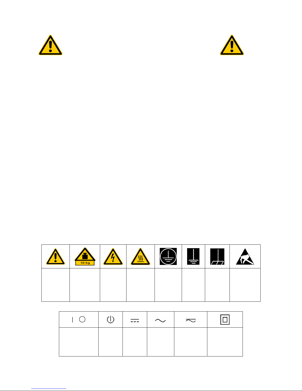
3
mV
0
12
3
4
56
7
89
.
-
ESC
ENTER
CANCEL
GHz
MHz
kHz
Hz
-dBm
dBm
dB
dB..
BACK
s
V
ms
mV
µs
µV
ns
nV
data input
0...9 input numbers
. input decimal point
– change sign
ESC – close input field (for uncompleted or
CANCEL already closed inputs, the original
entry is kept)
– erase the current entry in input field
(beginning of an input)
– close message window (status, error
and warning messages)
ENTER close the data input.
BACK – erase last character input for
uncompleted input
– restore previous input (undo)
see Chapter 3
Page 22

Front View R&S ESCI
1166.6004.12 1.2 E-2
Fig. 1-1 Front View
Page 23
R&S ESCI Front View
1166.6004.12 1.3 E-2
mV
0
12
3
4
56
7
89
.
-
ESC
ENTER
CANCEL
GHz
MHz
kHz
Hz
-dBm
dBm
dB
dB..
BACK
s
V
ms
mV
µs
µV
ns
nV
Keypad for data input
GHz s The units keys close the data
-dBm V input and define the multipli-
cation factor for each basic unit.
MHz ms For dimension-less or
dBm mV alphanumeric inputs, the units
keys have weight 1.
kHz µs They behave, in this case, like the
dB µVENTER key.
Hz ns
dB.. nV
see Chapter 3
4
FCTN
FREQ
MKR
AMPT
SPAN
MKR
MKR
FREQ Set frequency axis
SPAN Set span
AMPT Set level indication and configure
RF input.
MKR Select and set standard marker and delta
marker functions.
MKR-> Change instrument settings via markers
MKR Select further marker and delta
FCTN marker functions
see Chapter 4
5
MEAS TRIG
BW SWEEP
BW –Set resolution bandwidth, video
bandwidth and sweep time,
–Set coupling of these parameters
SWEEP Select sweep or set scan parameters
MEAS Select and set power measurements or
select detectors and measurement time
TRIG Set trigger sources
see Chapter 4
Page 24
Front View R&S ESCI
1166.6004.12 1.4 E-2
Fig. 1-1 Front View
Page 25
R&S ESCI Front View
1166.6004.12 1.5 E-2
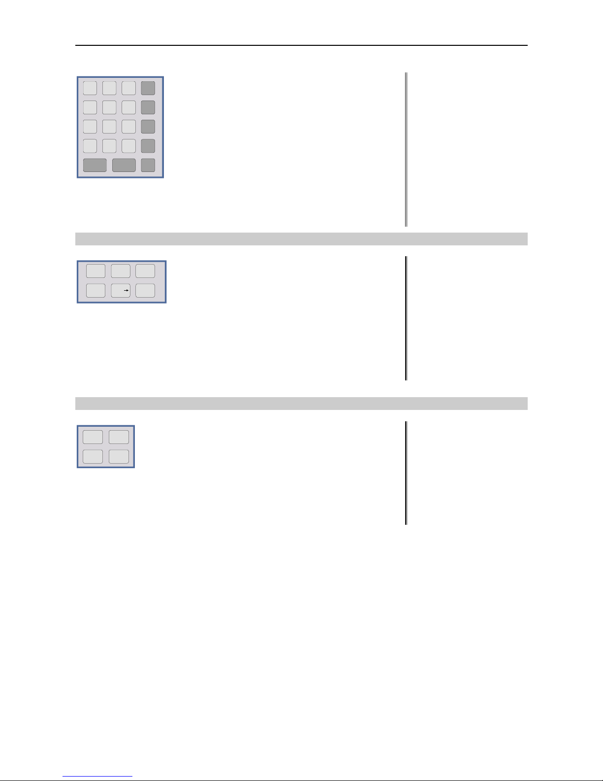
6
Key group for entering data and for cursor movement
Cursor keys – Move the cursor within the input
fields and tables.
– Vary the input value.
– Define the direction of movement
for the roll-key.
Roll-key – Vary input values.
– Move markers and limits.
– Select letters in the help line editor.
– Move cursor in the tables
– Close data input (ENTER)
see Chapter 3
7
3 1/2" diskette drive; 1.44 MByte
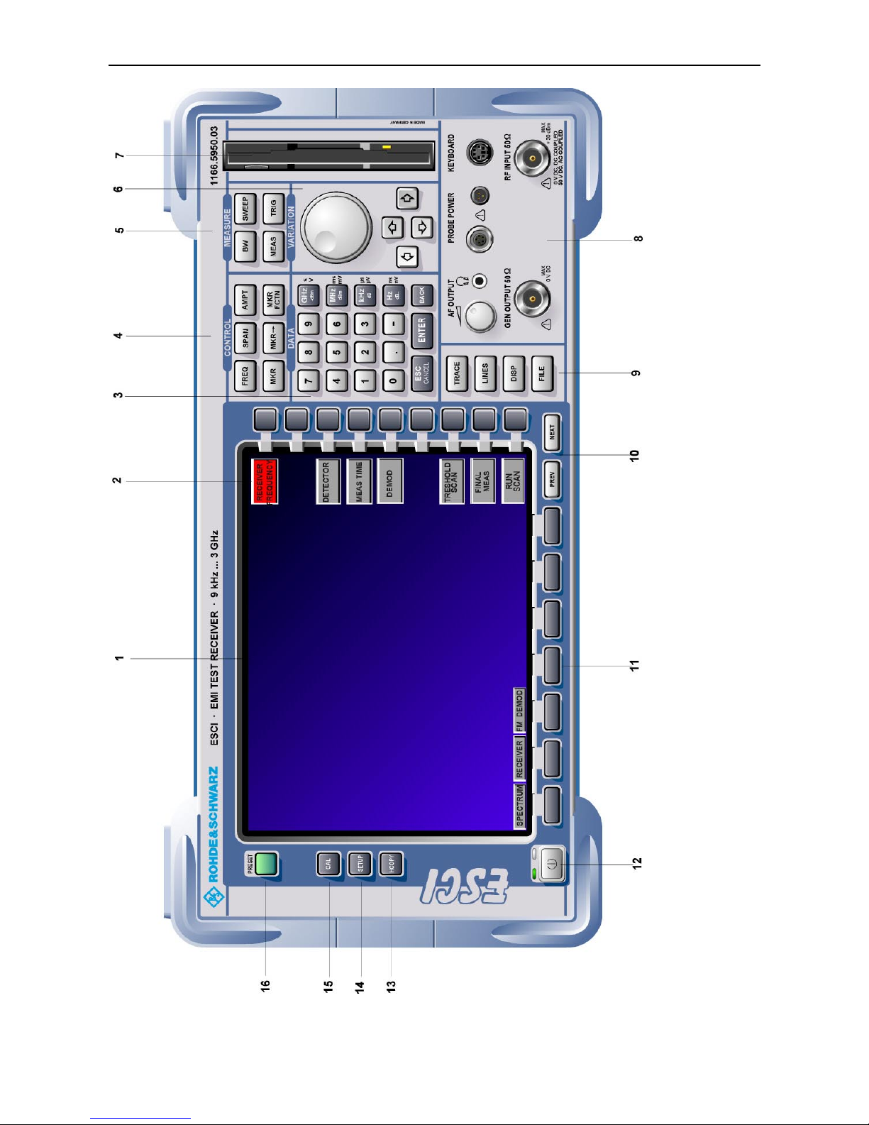
8
AF OUTPUT
Volume control
Head phone
connector
PROBE POWER Power supply and
coded socket
(+15 V/ -12 V) for
accessories
KEYBOARD Connector for an
external keyboard
GEN OUTPUT Generator output
(option FSP-B9)
see Chapter 8
RF INPUT RF input
Caution:
For DC-coupling, the max. DC
voltage is 0 V. For ACcoupling, the max. DC voltage
is 50 V. The maximum power
is 1 W ( 30 dBm at
≥
30 dB
attenuation)
see Chapter 8
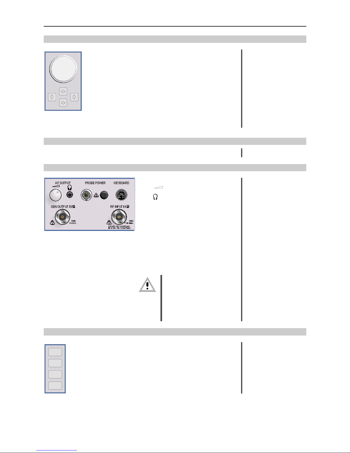
9
TRACE
LINES
DISP
FILE
TRACESelect and activate traces and detectors
LINES Set limit lines
DISP Configure display
FILE – Save and recall instrument data
– Configuration of memory media and data
see Chapter 4
Page 26

Front View R&S ESCI
1166.6004.12 1.6 E-2
Fig. 1-1 Front View
Page 27

R&S ESCI Front View
1166.6004.12 1.7 E-2
10
PREV NEXT
Menu-change keys
NEXT Change to side menu
PREV Call main menu
see Chapter 3
11
Hotkeys see Chapter 3
12
ON/STANDBY switch see Chapter 1
13
13
HCOPY
Configure and start a print job see Chapters 1 and 4
14
SETUP
Define general configuration see Chapter 4
15
CAL
Record correction data see Chapter 4
16
PRESET
Call default settings see Chapter 4
Page 28

Rear View R&S ESCI
1166.6004.12 1.8 E-2
625
=p` mf
I / Q DATA OUT
TG I IN
TG Q IN
20.4 - MHz OUT
REF IN
REF OUT
AUX CONTROL
USER PORT
IEC 2
NOISE
100 - 240 VAC
PKN=J=NKP=^
TG Q IN
LAN
17
18
25
24
23
22
21
20
19
30
29
28
27
26
31
32
625
EXT TRIG /
d^qb=fk
klfpb
plro`b
rp_
jlkfqlo `lj im q
SCPI
C
®
US
LR 114 19
S
Fig. 1-2 Rear View
Page 29

R&S ESCI Rear View
1166.6004.12 1.9 E-2
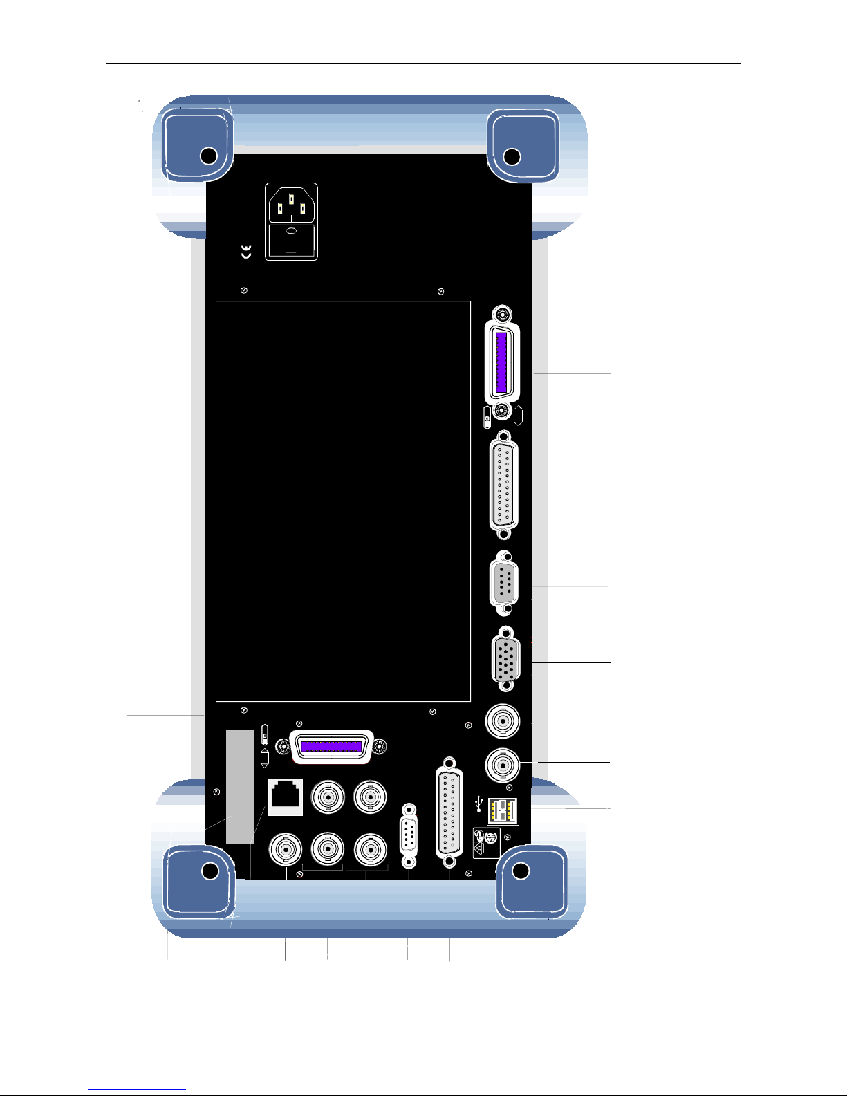
Rear View
17
IEC/IEEE bus-connector 2 for the external
generator (with Option R&S FSP-B10 only)
see Chapter 8
18
100 - 240 VAC
3.1 - 1.3 A
I 0
Power switch and AC power connector see Chapter 1
19
SC PI
625
IEC/IEEE bus-connector see Chapter 8
20
LPT
Parallel interface connector
(printer connector)
see Chapter 8
21
COM
Connector for a serial interface
(9-pin socket; COM)
see Chapter 8
22
MONITOR
Connector for an external monitor see Chapter 8
23
NOISE
SOURCE
Output connector for an external noise source see Chapter 8
24
EXT TRIG /
GATE IN
Input connector for an external trigger or an
external gate signal
see Chapter 8
Page 30
Rear View R&S ESCI
1166.6004.12 1.10 E-2
625
=p` mf
I / Q DATA OUT
TG I IN
TG Q IN
20.4 - MHz OUT
REF IN
REF OUT
AUX CONTROL
USER PORT
IEC 2
NOISE
100 - 240 VAC
PKN=J=NKP=^
TG Q IN
LAN
17
18
25
24
23
22
21
20
19
30
29
28
27
26
31
32
625
EXT TRIG /
d^qb=fk
klfpb
plro`b
rp_
jlkfqlo `lj im q
SCPI
C
®
US
LR 114 19
S
Fig. 1-2 Rear View
Page 31

R&S ESCI Rear View
1166.6004.12 1.11 E-2
25
USB
USB interface
see Chapter 8
26
USER PORT
USER PORT Output/input. TTL levels
(Low < 0,4 V, High > 2 V).
Internal +5 V power supply voltage.
Maximum load current 100 mA.
see Chapter 8
27
AUX CONTROL
AUX Control connector for controlling the external
generator (option R&S FSP-B10 only)
28
REF IN REF OUT
REF IN Input connector for an external
reference (10 MHz)
REF OUT Output connector for an internal
reference (10 MHz)
29
TG I IN TG Q IN
TG I IN Input connector for external modulation
of tracking generator (option FSP-B9)
TG Q IN Input connector for external modulation
of tracking generator (option FSP-B9)
see Chapter 4
30
20.4 - MHz OUT
Output connector for 20.4 MHz IF
(not if option FSP-B6 is built in)
see Chapter 8
CVS IN/OUT
Selectable CCVS input/output
(only if option FSP-B6 is built in)
see Chapter 4 and 8
31
LAN
LAN Interface (FSP-B16) see Chapter 4
32
Reserved for options
Page 32

Getting Started with the Instrument R&S ESCI
1166.6004.12 1.12 E-1
Getting Started with the Instrument
The following section describes how to activate the instrument and how to connect external devices
such as printer and monitor.
Chapter 2 explains the operation of the instrument using simple measurement examples.
Important:
Prior to switching on the instrument, make sure that the following conditions are fulfilled:
• The instrument cover is in place and tightly screwed on
• Fan openings are not obstructed
• Signal levels at the inputs are within specified limits
• Signal outputs are connected correctly and not overloaded.
Any non-compliance may cause damage to the instr ument .
Preparing the Instrument for Operation
remove protective caps
! Take the instrument out of the packaging and check whether the
items listed in the pack ing list and in the lists of acces sories are all
included.
! Remove the two protective covers from the front and rear of the
R&S ESCI and carefully check the instrument for damage.
! Should the instrument be damaged, immediately notify the carrier
and keep the box and packing material.
! For further transport or shipment of the R&S ESCI, the original
packing should be used. It is recommended to k eep at least the two
protective covers of the front and rear panels in order to prevent
damage to the controls and connectors.
Setting Up the Instrument
Standalone Operation
The instrument is designed for use under general laboratory conditions. The ambient conditions required
at the site of operation are as follows:
Wrist strap with cord
Building ground
Floor mat
Ground connection
of operational site
Heel strap
• The ambient tem perature m us t be in the range spec ified in
the data sheet.
• All fan openings mus t be unobstructed and the air flow at
the rear panel and at the side-panel perforations must be
unimpeded. The distance to the wall should be at least
10 cm.
• The mounting surface should be flat.
• To avoid damage of electronic components of the DUT
due to electrostatic discharge on manual touch, protective
measures against electrostatic discharge are
recommended.
Page 33

R&S ESCI Getting Started with the Instrument
1166.6004.12 1.13 E-1
Safety Instruction for Instruments with Tiltable Feet
Warning
The feet must be fully folded in or out. Only in this way can the stability of the
instrument be guaranteed and reliable operation be ensured. W ith the feet out, the
total load for the feet must not exceed 500 N (own weight and additional units put
onto the instrument). These units must be sec ured against slipping (e.g. by locking
the feet of the unit at the top side of the enclosure).
YRMMk
When shifting the instrument with the feet out, the feet might c ollapse and fold in. To
avoid injuries, the instrument must therefore not be shifted with the feet out.
The instrument can be operated in any position.
Rackmounting
Important:
For rack installation, ensure that the air flow at the s ide-panel per for ations and the air
exhaust at the rear panel are not obstructed.
The instrument may be installed in a 19" rack by using a rack adapter kit (Order No. see data sheet).
The installation instructions are part of the adapter kit.
Page 34

Getting Started with the Instrument R&S ESCI
1166.6004.12 1.14 E-1
EMC Safety Precautions
In order to avoid electromagnetic interference (EMI), the instrument may be operated only with all covers
closed. Only adequately shielded signal and control cables may be used (see recommended
accessories).
Connecting the Instrument to the AC Supply
The R&S ESCI is equipped with an AC voltage selection feature and will automatically adapt itself to the
applied AC voltage (range: 100 to 240 V AC, 40 to 400 Hz). External voltage selection or adaptation of
the fuses are not necessary. The AC power connector is located on the rear panel (see below).
o
I
Power connector
! Connect the instrument to the AC power source using the AC
power cable delivered with the instrument.
As the instrument is designed according to the regulations for
safety class EN61010, it must be connected to a power outlet
with earthing contact.
Switching the Instrument On/Off
Caution:
Do not power down during booting. Such a switch-off may lead to corr uption of
the hard disk files.
AC power switch on the rear panel
Power switch
I 0
Power connec tor
Power switch
Position I = ON
In the I position, the instrument is in st andby mode or in
operation, depending on the position of the
ON/STANDBY key at the front of the instrument.
Note:
The AC power switch may remain ON continuously.
Switching to OFF is only required when the instrument
must be completely removed from the AC power source.
Position O = OFF
The 0 position implies an all-pole disconnection of the
instrument from the AC power source.
Page 35

R&S ESCI Getting Started with the Instrument
1166.6004.12 1.15 E-1
ON/STANDBY switch on the front panel
ON STANDBY
Standby switch
The ON/STANDBY switch activates two different oper ating
modes indicated by coloured LEDs:
Operation ON - ON/STANDBY is depressed
The green LED (ON) is illuminated. The instrument is
ready for operation. All modules within the instrument are
supplied with power.
Caution:
In standby mode, the AC
power voltage is present
within the instrument
STANDBY - ON/STANDBY switch is not pressed.
The yellow LED (STANDBY) is illuminated. Only the
power supply is supplied with power and the quartz oven
is maintained at normal operating temperature.
Switching On the Instrument
! In order to switch on the R&S ESCI, set the power switch on the rear panel to position I.
! Set the R&S ESCI to operating mode by pressing the ON/STANDBY key on the front panel. The
green LED must be illuminated.
Startup Menu and Booting
After switching on the instrum ent, a message indicating the ins talled BIOS version (e.g. Analyzer BIOS
Rev. 1.2) appears on the screen for a few seconds.
Subsequently Windows XP is booted fir st and after that the instrument firm ware will boot. As soon as
the boot process is finished the inst rument will start measuring. T he settings used will be the one that
was active when the instrument was previously switched off, provided no other device c onf igur ation than
FACTORY had been selected with STARTUP RECALL in the FILE menu.
Switching Off the R&S ESCI
! Switch the ON/STANDBY key on the front panel to standby mode by pressing it once.
The R&S ESCI will write the current instrum ent settings to disk before perfor ming a Windows XP
shutdown. At the end of the shutdown procedure the power supply will be switched to STANDBY
mode.
The yellow LED must be illuminated.
Only when removing the R&S ESCI completely from t he A C p o w e r s ou r c e :
! Set the power switch at the rear panel to position 0.
Page 36

Function Test R&S ESCI
1166.6004.12 1.16 E-1
Power-Save Mode
Display:
The R&S ESCI offers the possibility of switching on a power-save mode for the screen display. The
backlighting will be switched off if no entry is made on the front panel (key, softkey or hotkey as well as
spinwheel) during the selected response time.
In order to switch on the power-save mode:
1. Call the DISPLAY - CONFIG DISPLAY submenu to configure the screen display:
! Press DISP key
! Press CONFIG DISPLAY softkey
2. Activate the save mode
! Press DISPLAY PWR SAVE softkey.
The softkey is highlighted in colour, thus indicating that the power-save mode is on. At the
same time the data entry for the delay time is opened.
3. Define the delay time
! Enter the required response time in minutes and confirm the entry using the ENTER key.
The screen will be blanked out after the selected time period has elapsed.
Hard disk:
A power-save mode is preset f or the built-in hard disk which is automatic ally closed down 15 minutes
after the last access.
Recalling the Most Recent Instrument Settings
The R&S ESCI stores its curr ent instrument settings onto the hard disk every time it is s witched off via
the ON/STANDBY key. After each power-on, the R&S ESCI is reloaded with the operational parameters
which were active just prior to the last power-off (STANDBY or AC power OFF) or were set with
STARTUP RECALL (see Chapter 4 "Saving and Recalling Data Sets").
Note: Storing the current instrument settings is not possible if the instrument is s witched off us ing
the POWER ON switch at the rear panel or when unplugging the mains cord. After poweron the instrument settings stored previously on the hard disk will be loaded in this case.
Function Test
After turning on the AC power, the R&S ESCI will display the following message on the display screen:
Rohde & Schwarz GmbH & Co. KG
Analyzer BIOS Vx.y
After appearance of the above message, a selftest of the controller hardware is performed.
Subsequently, the Windows XP controller boots and the measurement screen will appear.
The system self- alignment is activated via CAL key, CAL TOTAL softkey. The individual resu lts of the
self-alignment (PASSED / FAILED) can be displayed in the CAL menu (CAL RESULTS).
With the aid of the built-in selftest functions (SETUP key, SERVICE, SELFTEST soft keys), the
functional integrity of the instrument can be verified and/or defective modules can be localized.
Page 37

R&S ESCI Windows XP
1166.6004.12 1.17 E-1
Windows XP
Caution:
The drivers and programs used under Windows XP are adapted to the measuring
instrument. In order to prevent the instrument functions from damage, the settings
should only be modified as described below.
Existing software may only be modified using update s oftware released by Rohde &
Schwarz.
Additionally only programs authorized by Rohde & Schwarz for use on the R&S ESCI
may be run on the instrument.
Do not power down during booting. Such a switch-off may lead to corruption of
the hard disk files.
The instrument runs under the operating system Windows XP Embedded. The computer can be used to
install and configure device drivers that were authorized by Rohde & Schwarz. Any further use of the
computer function is only allowed under the conditions described in this operating manual.
Login
Windows XP requires a login process , during which the user is asked for identif ication by entering his
name and password. As a factory default the instrument is configured for Auto Login, i.e. the login is
performed automatic ally and in the backgr ound. The user name used for this is "instrum ent" and the
password is also "instrument" (in small letters).
Administrator level
The NT user account used for the autologin function has administrator access rights.
Windows XP Service Packs
The Windows XP Embedded system installed on the instrument includes Service Pack 1 for XP
Embedded.
Any service pack not approved by Rohde & Schwarz must not be installed since malfunctions
may occur. These malfunctions could impair measurements that are correctly performed on the
instrument and necessitate a repair.
The user is especially warned against using Service Pack s of Windows XP Hom e or of the Prof ess ional
Edition, since these Service Packs are not compatible with Windows XP Embedded.
Calling the Windows XP start menu
The Windows XP start menu is called using the key combination <CTRL> <ESC>. It is possible to
access the required subm enus f rom the star t m enu by means of the m ouse or the cur sor k eys. In order
to return to the measurement screen the button "R&S Analyzer Interface" in the W indows XP task bar
can be used.
Page 38

Connecting an External Keyboard R&S ESCI
1166.6004.12 1.18 E-1
Connecting an External Keyboard
Caution:
Connect the keyboard only when the instrument is switched off
(STANDBY). Otherwise, proper functioning cannot be ens ured due to interactions with
the firmware.
The R&S ESCI allows an external PC keyboard to be connected to the 6-pin PS/2 connector labelled
KEYBOARD on the front panel or to the USB interface on the rear panel.
KEYBOARD
USB
The keyboard makes it easier to enter comments, file names, etc, when measurements are performed.
If the keyboard is to be connected to the PS/2 connector, the PSP-Z2 keyboard (Order No.
1091.4100.02, English) is recomm ended. This keyboard includes not only the PC keyboard but also a
trackball for controlling the mouse.
Keyboards and mouse devices in line with the USB standard 1.1 are suitable f or connection to the USB
interface.
The keyboard (except for PSP-Z2, see above) will automatically be recognized after connection. The US
keyboard assignment is the default setting. Special settings such as ref resh rate can be performed in
the Windows XP menu START - SETTINGS - CONTROL PANEL - KEYBOARD.
Chapter 8 contains the interface description for the connectors.
Page 39

R&S ESCI Connecting a Mouse
1166.6004.12 1.19 E-1
Connecting a Mouse
To make W indows XP operation easier, the R&S ESCI allows a mouse to be connected to the USB
interface on the rear panel.
USB
Microsoft and Logitech mouse types are supported.
Note. The recommended keyboard PSP-Z2 is equipped with a trackball for mous e c ontrol. Connec ting
an additional mouse will cause interface conflicts and lead to malfunctions of the instrument.
After connection the mouse is automatically recognized. Special settings suc h as mouse cursor s peed
etc, can be performed in the Windows XP menu START - SETTINGS - CONTROL PANEL - MOUSE.
Chapter 8 contains the interface description for the connector.
Page 40

Connecting an External Monitor R&S ESCI
1166.6004.12 1.20 E-1
Connecting an External Monitor
Caution:
The monitor may only be connected when the instrument is sw itched off (STANDBY).
Otherwise, the monitor may be damaged.
Do not modify the screen driver (dis play type) and display configuration since this will
severely affect instrument operation.
The instrument is equipped with a rear-panel MONITOR connector for the connection of an external
monitor.
MONITOR
After connecting the external monitor the instrument needs to be rebooted in order to recognize the
monitor. After that the measurement screen is displayed on both the external monitor and the
instrument. Further settings are not necessary.
Page 41

R&S ESCI Connecting a Printer
1166.6004.12 1.21 E-1
Connecting a Printer
A printer can be connected while the instrument is running.
The R&S ESCI allows two different printer configurations for printing a hardcopy to be created plus
switchover between these two configurations. The DEVICES table in the HCOPY menu shows the
available selection of installed printers (see section 4.4 "Documentation of Measurement Results").
The interfaces for connecting printers are on the rear panel:
LPT
USB
Chapter 8 contains the interface description for the connectors.
Selecting a Printer
Before a hardcopy can be printed, the printer has to be selected from the "HCOPY" menu.
In the following example, an HP DeskJet 660C printer that was preinstalled for LPT1 is selected as
DEVICE2 for hardcopies of the screen content.
COLORS
HCOPY
DEVICE
SETUP
DEVICE
1 2
! Press the HCOPY key.
The HCOPY menu will open.
DEVICE
1 2
! Press the DEVICE 1/2 softkey.
Device 2 will become the active output
unit.
Note:
If the printer is to be operated as device 1,
this step can be omitted.
Page 42

Connecting a Printer R&S ESCI
1166.6004.12 1.22 E-1
DEVICE
SETUP
! Press the DEVICE SETUP softkey.
The HARDCOPY SETUP table opens and
displays the selection of output formats.
The current selection "Clipboard" is
highlighted and marked with a dot in the
option button.
! Use the cursor key
to move the
selection bar to "Printer" and press
ENTER.
Windows for selecting a printer (Name),
printing to file (Print to File) and selecting
printout orientation (Orientation) are
displayed.
! Use the curs or key to set the selection
bar to "Name" and press ENTER .
The list of available printer types appears.
! Use the cursor key
/ or the
spinwheel to move the selection bar to the
"HP DeskJet 660C" printer and press
ENTER.
The list closes and the selected printer
appears in the "Name" field.
Note:
If the desired printer is not available in the
selection list, its driver must first be
installed.
For further information, see sections
"Installation of Plug&Play Printers",
"Installation of Non-Plug&Play Printers"
and "Installation of Network Printers".
Page 43

R&S ESCI Connecting a Printer
1166.6004.12 1.23 E-1
VARIATION
! Press the cursor key or turn the
spinwheel until the "Close" button is
reached.
Further settings can still be made:
"Print to File" redirects printing to a f ile. In
this case, the system prompts you for a file
name when printing is started.
! The selection is activated by pressing
ENTER or the spinwheel.
"Orientation" is used to switch between
portrait and landscape format.
! To change the selection, open the list by
pressing ENTER and select the desired
orientation with the cursor key
/ . T o
close the list, press ENTER again.
The "Close" button is used to complete the
setup.
! Press ENTER as soon as the "Close"
button is available.
The dialog closes. Printing will now be
performed according to the selected settings.
PRINT
SCREEN
Start printing
! Press the PRINT SCREEN softkey.
A hardcopy of the screen contents will be
printed.
Page 44

Connecting a Printer R&S ESCI
1166.6004.12 1.24 E-1
The factory setting for DEVICE 2 is "Clipboard". In this case, the printout will be copied to the
Windows XP clipboard which is supported by most Windows applications. The contents of the
clipboard can be pasted directly into a document via EDIT - PASTE.
Table 1-1 F actory settings for DEVICE 1 and DEVICE 2 in the HCOPY menu shows the factor y
settings for the two output devices.
Table 1-1 Factory settings for DEVICE 1 and DEVICE 2 in the HCOPY menu
Setting Selection in
configuration table
Setting for DEVICE 1 Setting for DEVICE 2
Output device DEVICE WINDOWS METAFILE CLIPBOARD
Output PRINT TO FILE YES ---
Orientation ORIENTATION --- ---
Installation of Plug&Play Printers
The installation of Plug&Play printers under Windows XP is quite simple:
After the printer is connected and s witched on, Windows XP autom atically recognizes it and installs its
driver, provided the driver is included in the XP installation.
If the XP printer driver is not found, W indows XP prom pts you to enter the path f or the corresponding
installation files. In addition to pre-installed driver s, a number of other printer drivers can be f ound in
directory D:\I386.
Note: When installing new printer driver s, you will be prompted to indicate the path of the new
driver. This path may be on a disk in dr ive A. Alternatively, the driver can be loaded via a
memory stick or USB CD-ROM drive (see section "Connection of USB Devices").
Installation of Non-Plug&Play Printers
Note: The dialogs below can be controlled either from the front panel or via the mouse and
keyboard (see sections "Connec ting a Mouse" and "Connecting a Keyboard"). Mouse and
PC keyboard are absolutely essential for configuring network printers.
A new printer is installed with the INSTALL PRINTER softkey in the HCOPY menu.
COLORS
HCOPY
DEVICE
SETUP
DEVICE
1 2
! Press the HCOPY key.
The HCOPY menu will open.
Page 45

R&S ESCI Connecting a Printer
1166.6004.12 1.25 E-1
NEXT
! Press the NEXT key to open the side
menu.
INSTALL
PRINTER
! Press INSTALL PRINTER to open the
Printers and Faxes dialog window.
! Select Add Printer in the list using the
spinwheel.
! Highlight the selected item with CURSOR
RIGHT and press ENTER or the
spinwheel to confirm the selection.
The Add Printer Wizard is displayed.
! Select NEXT with the spinwheel and press
the spinwheel for confirmation.
Local or Network Printer can be selected.
! To install a local printer, select Local
printer attached to this computer with the
spinwheel. Press the spinwheel for
confirmation and continue with the "Local
Printer" section.
! To install a network printer, select A
network printer or a printer attached to
another computer. Press the spinwheel for
confirmation and continue with the
"Network Printer" section.
Page 46

Connecting a Printer R&S ESCI
1166.6004.12 1.26 E-1
Local Printer
In the following example, a Star LC24 printer is connected to the LPT1 interface and configured as
DEVICE2 for hardcopies of screen contents. The Add Printer Wizard has already been opened as
described in the section "Starting the Add Printer Wizard" .
! To selec t the USB interface, open the list
of ports by clicking the spinwheel.
Select the printer port with
spinwheel/arrow keys and confirm by
pressing the spinwheel. The selection lis t
is closed again.
! To s elect the LPT c onnector, the selection
list need not be opened.
! Place the cursor on the Next button and
confirm by pressing the spinwheel.
The "Install Printer Software" dialog is
opened.
! Select the desir ed manuf acturer ("Star") in
the Manufacturer table using the up / down
keys.
Page 47

R&S ESCI Connecting a Printer
1166.6004.12 1.27 E-1
! Go to the Printers list with the spinwheel.
! Select the desir ed printer type (Star LC24-
200 Colour) using the up / down keys and
confirm with ENTER.
Note:
If the desired printer type is not in the list, the
respective driver is not installed yet. In this
case click the HAVE DISK button with the
mouse key. You will be prompted to ins ert a
disk with the corresponding printer driver.
Press OK and select the desired printer
driver.
! The printer name can be changed as
required in the Printer name entry field
(max. 60 characters). A PC keyboard is
required in this case.
! Use the spinwheel to selec t Yes or No for
the default printer.
! Choose the desired status with the up
/down keys.
! Confirm with ENTER.
The Printer Sharing dialog is opened.
! Exit the dialog with ENTER.
The Print Test Page dialog is opened.
Page 48

Connecting a Printer R&S ESCI
1166.6004.12 1.28 E-1
! Exit the dialog with ENTER.
The Completing the Add Printer Wizard
dialog is opened.
! Check the displayed s ettings and exit the
dialog with ENTER.
The printer is installed. If Windows finds
the required driver files, the installation is
completed without any further queries.
If W indows cannot find the required driver
files, a dialog is opened where the path for
the files can be entered.
! Select the Browse button with the
spinwheel and confirm with by pressing
the spinwheel.
The Locate File dialog is opened.
Page 49

R&S ESCI Connecting a Printer
1166.6004.12 1.29 E-1
! Tur n the spinwheel to select the directory
and path D:\I386 and press it to confirm
the selection.
If the selected item is not pr inted on a blue
background, it must be marked with the
cursor up / down keys before it can be
activated by pressing the spinwheel.
! Select the driver file with the spinwheel
and confirm by pressing the spinwheel.
The file is included in the Files Needed
dialog.
Note:
If the desired file is not in the D:\I386
directory, a disk with the driver file is
needed. In this case, exit the dialog with
ESC and repeat the selection starting from
the "Files needed" dialog.
! Select the OK button with the spinwheel
and press the spinwheel to confirm.
The installation is completed.
Finally, the instrument must be configured for printout with this printer using the softkeys DEVICE
SETUP and DEVICE 1/2 in the hardcopy main menu (see section "Selecting a printer").
Page 50

Connecting a Printer R&S ESCI
1166.6004.12 1.30 E-1
Configuring a Network Printer
! To select a network printer, click the option
"A network printer or a printer attached to
another computer".
Continue with Next.
! Click Browse for a printer and then Next.
A list of selectable printers is displayed.
! Mark the desired printer and select it with
OK.
Page 51

R&S ESCI Connecting a Printer
1166.6004.12 1.31 E-1
! Confir m the subsequent prom pt to install a
suitable printer driver with "OK".
The list of available printer drivers is
displayed.
The manufacturers are listed in the lefthand table, the available printer drivers in
the right-hand table.
! Select the manufacturer from the
Manufacturers table and then the printer
driver from the Printers table.
Note:
If the desired type of output device is not
shown in the list, the driver has not yet been
installed. In this case, click the "HAVE DISK"
button. You will be prompted to insert a disk
with the corresponding printer driver. Insert
the disk, select "OK" and then choose the
desired printer driver.
! Click Next.
If one or more printers have already been
installed, this window queries whether the
printer last installed is to be used as the
default printer for the Windows XP
applications. The default selection is No.
! Start the printer driver installation with
Finish.
Finally, the instrument has to be configured for printout with this printer using the softkeys DEVICE
SETUP and DEVICE 1/2 in the hardcopy menu (see section "Selection of a Printer").
Page 52

Connection of USB Devices R&S ESCI
1166.6004.12 1.32 E-1
Connection of USB Devices
Up to two USB devices can be directly connected to the analyzer via the USB interface on the rear of the
R&S ESCI. This number can be increased as required by interconnecting USB hubs.
Owing to the wide variety of available USB devices, the R&S ESCI can be expanded with almost no
limitations. The following list shows a selection of USB devices suitable for the R&S ESCI:
• Power Sensor R&S NRP-Z11 or R&S NRP-Z21 (Adapter Cable R&S NRP-Z4 required)
• Pendrive (memory stick) for easy data transfer from/to the PC (e.g. firmware updates)
• CD-ROM drive for easy installation of firmware applications
• PC keyboard for entering comments, file names, etc
• Mouse for easy operation of Windows dialogs
• Printer for documentation of measurement results
• Modem for remote control of the R&S ESCI over great distances
The installation of USB devices is quite simp le under Windows XP s ince all USB devic es are Plug&Play.
Apart from the keyboard and the mouse, all USB devices can be connected to or disconnec ted fr om the
R&S ESCI while the instrument is running.
After the instrument is connected to the USB interface, Windows XP automatically searches for a
suitable device driver.
If Windows XP does not find a suitable driver, you will be prompted to specify a directory where the
driver software can be found. If the driver software is on a CD, a USB CD-ROM should first be
connected to drive to the R&S ESCI.
As soon as the connection between the R&S ESCI and the USB device is interrupted, Windows XP will
again recognize the modified hardware configuration and will deactivate the corresponding device driver.
Example:
Connecting a pendrive (memory stick) to the R&S ESCI:
1. After the pendrive is connected to the USB interface, Windows XP will recognize the newly
connected hardware:
2. Windows XP installs the corresponding driver.
After successful installation, XP signals that the unit is ready for operation:
Page 53

R&S ESCI Connection of USB Dev ices
1166.6004.12 1.33 E-1
3. The pendrive is now available as a new drive and is displayed in Windows Explorer:
The pendrive can be used as a normal drive to load or save files.
4. If the pendrive is no longer required or if files are to be transferred to another computer, the
pendrive is simply disconnected. Windows XP will then deactivate the driver.
If the corresponding drive is still selected in Explorer, an error message will be displayed indicating
that the drive is no longer available.
Page 54

Installing Windows XP Software R&S ESCI
1166.6004.12 1.34 E-1
Installing Windows XP Software
Authorized Windows XP Software for the Instrument
The driver software and the system s ettings of Windows XP are adapted to the measur ement functions
of the instrument. Correc t operation of the instrument c an therefore be guaranteed only if the software
and hardware used are authorized or supplied by Rohde & Schwarz.
The following program pack ages have been successfully tested for com patibility with the instrument's
software:
• R&S FS-K3 – software for measuring noise factor and gain
• R&S FS-K4 – software for measuring phase noise
• R&S Power Viewer
(virtual power sensor for displaying the results of Power Sensors NRP-Z11 and -Z21)
• Windows XP remote desktop
• FileShredder – for deleting files from the hard disk
• Symantec Norton AntiVirus – software for protection against viruses
The use of other software or hardware may cause failures in the functions of the R&S ESCI.
A current list of the software author ized for use on the R&S ESCI can be obtained from your nearest
Rohde & Schwarz agency (see list of addresses).
Page 55

R&S ESCI Contents - Getting Started
1166.6004.12 I-2.1 E-2
Contents - Chapter 2 "Getting Started"
4 Getting Started
Measurement Example.....................................................................................................................2.1
Example of Level and Frequency Measurement......................................................................2.2
Measurement.................................................................................................................2.2
Main Test Receiver Functions .......................................................................................2.2
Measurement Sequence - Level and Frequency Measurement....................................2.2
Page 56

Contents - Getting Started R&S ESCI
1166.6004.12 I-2.2 E-2
Page 57

R&S ESCI Example - Level and Frequency Measurement
1166.6004.12 2.1 E-2
2 Getting Started
Chapter 2 provides a fast introduction to operation by guiding the user step by step through a
measurement example.
Before starting any measurement with the R&S ESCI, please note the instr uctions given in chapter 1 f or
putting the instrument into operation. In chapters 3 you will find detailed information on custom izing the
instrument and the display.
For a systematic explanation of all m enus, functions and par ameters and back ground inform ation refer
to the reference part in chapter 4.
Measurement Examples and Applications
This section descr ibes a typical and simple meas urement tas k for an EMI tes t receiver. Each operating
step is explained with the aid of R&S ESCI for rapid f amiliarization of the us er without the need to know
all the details of the operating functions.
In the introductory example a standard measurement of level and frequency is perfor med with the aid
of the SCAN table. This measurem ent is an over view and precer tif ic ation measurement to be perf ormed
before the final standard-conformal measurement is carried out.
Note: If unknown (RFI) signals are to be measured, it is strongly recommended to provide for at least
10 dB RF attenuation at the RF input in order to protect the input circuit.
In the following example the test receiver is s et to def ault values in the r eceiver mode. The default s etup
is activated by pressing first the RECEIVER hotkey and then the PRESET key. The main default
parameters are listed in the following table.
Table 2-1 Default parameters after preset in recveiver mode
Parameter Setting
Receiver frequency 100 MHz
RF attenuation Auto
Preamplifier Off
Detector AV
Measurement time 100 ms
RES bandwidth 120 kHz
Demodulator Off
Trigger Free run
Page 58

Example - Level and Frequency Measurement R&S ESCI
1166.6004.12 2.2 E-2
Example of Level and Frequency Measurement
Measurement
Measurement and display of RFI signal levels versus frequency is one of the most frequent tasks
performed by an EMI test receiver. In the cas e of unknown signals, PRESET values will mostly be used
for the measurem ent. If levels higher than +137 dBµV (10 dB RF attenuation) are expected or pos sible,
a power attenuator has to be connected in front of the test receiver input. Very high levels may
otherwise damage or destroy the attenuator or input mixer.
Main Test Receiver Functions
The main functions required for the level and frequency measurement are setting the SCAN table
(START FREQUENCY, STOP FREQUENCY, STEPSIZE) , selecting the res olution (IF) bandwidth (RES
BW), setting the measurement time (MEAS TIME) and selecting the detec tors ( eg peak or average) and
MARKER functions required for the analysis.
Measurement Sequence - Level and Frequency Measurement
In this example the spectrum of the signal pres ent at RF INPUT is recorded in the fr equency range 150
kHz to 30 MHz. The scan table and associated parameters are manually set.
The example is generally suitable for all fast pre-compliance measurements required for measuring
unknown noise spectra of DUTs in the development stage and for modifying prototypes and can be
used as a basis for final tests later on.
The high speed of fully synthesized scans, the frequency and amplitude accurac y and the wide dynamic
range of Test Receiver R&S ESCI are of utmost importance and very useful for these measurements.
The following measurement steps are performed:
1. PRESET of instrument.
2. Selecting RECEIVER mode (RECEIVER hotkey).
3. Programming the scan table: stop frequency 30 MHz, 1 scan range
4. Selecting detectors, measurement bandwidth and measurement time
5. Applying the signal (RF input)
6. Starting the scan
7. Level analysis in the frequency domain using MARKER function
8. Setting the SPLIT SCREEN function
9. Tuning to the receiver frequency using the TUNE TO MARKER function
10. From overview to standard-conformal measurement
11. Storing test results, tables and diagrams
Page 59

R&S ESCI Example - Level and Frequency Measurement
1166.6004.12 2.3 E-2
PRESET
RECEIVER
1. Resetting the instrument and
2. Selecting the RECEIVER mode
! Press first the PRESET key and then the
RECEIVER hotkey.
The main receiver m enu is opened. The receiver
mode is set.
The following screen is displayed:
Fig.2-1 Display after selecting the default setup in receiver mode
USE CURR
SETTINGS
USE SCAN
TABLE
SWEEP
USE SCAN
TABLE
3. Programming a SCAN table
! Press the SWEEP key.
! In the SW EEP menu press the USE SCAN TABLE
softkey.
A menu is displayed where the whole display range
can be defined and divided into scan subranges.
After PRESET a scan range of 150 k Hz to 1 GHz is
preset on the frequency axis.
Now the stop frequency is set to 30 MHz.
Page 60

Example - Level and Frequency Measurement R&S ESCI
1166.6004.12 2.4 E-2
Fig.2-2 Scan range after selecting default setup with PRESET
! Press the DOWN cursor in the DATA VARIATION
field repeatedly until a line in the scan table is
marked.
! Press the RIGHT cursor key in the DATA
VARIATION field.
An entry in the RANGE 2 column is marked.
DELETE
RANGE
! Press the DELETE RANGE softkey.
All entries in column RANGE 2 are cleared.
The following scan table is now displayed:
Page 61

R&S ESCI Example - Level and Frequency Measurement
1166.6004.12 2.5 E-2
Fig.2-3 Modified SCAN table for preparing a SCAN
After editing the scan subrange, the frequency
display has to be adapted to the new settings. The
lowest START frequency of SCAN range 1 and the
highest STOP frequency of the subsequently
defined subranges are used for defining the start
and stop frequencies of the graphic s display. In the
example the limit frequencies of SCAN RANGE 1
are therefore also the limits of the graphics display.
ADJUST
AXIS
! Press the ADJUST AXIS softkey.
The respective frequency values in the table are
transferred to adapt the display.
PREV
! Press the menu change key PREV.
The USE SCAN TABLE submenu is closed.
Page 62

Example - Level and Frequency Measurement R&S ESCI
1166.6004.12 2.6 E-2
4. Selecting detectors
Up to three detectors can be connected in parallel to
simultaneously display the amplitude at every frequency
as a function of detector weighting. When a parallel
detector is selected, the slowest detector (in the sense
of a calibrated measurement) determ ines the speed or
the total measurement tim e required for the scan. The
fastest scan is performed when the peak detector is
used as the sole detector.
In the example, the peak detector (trace 1) and the
average detector (trace 2; default) are used in an
overview measurement.
CLEAR /
WRITE
SELECT
TRACE
MAX HOLD
TRACE
! Press the TRACE key.
The TRACE menu is opened where the trace can
be selected and the detector for the select ed trace
can be determined.
SELECT
TRACE
! Press the SELECT TRACE softkey.
A data input field is opened where the number of
the trace, here 1, can be entered. The input is
confirmed with the ENTER key.
MAX
PEAK
DETECTOR
MIN
PEAK
QUASIPEAK
! Press the DETECTOR softkey.
The DETECTOR menu is opened where different
detectors, MAX PEAK, MIN PEAK, QUASIPEAK,
AVERAGE and RMS, can be selected for trace 1.
MAX
PEAK
! Press the MAX PEAK softkey.
The peak detector is selected.
Page 63

R&S ESCI Example - Level and Frequency Measurement
1166.6004.12 2.7 E-2
! Repeat the settings for trace 2.
! Press the CLEAR / WRITE softkey.
In the DETECTOR menu select the AVERAGE
detector.
5. Applying the signal
! Connect RF cable to the RF input.
6. Starting the scan
! Press the SWEEP key.
The SWEEP/SCAN menu is openend.
STOP
SCAN
HOLD
SCAN
RUN
SCAN
! Press the RUN SCAN softkey.
The measurement with the selected PEAK and
AVERAGE detectors is continuously repeated
because the default setting CONTINUOUS SCAN
remains unchanged.
At the same time the HOLD SCAN and STOP
SCAN s oftkeys are displayed with the aid of which
the scan can be interrupted (HOLD SCAN)
or
aborted (STOP SCAN).
In the example the scan should be aborted.
STOP
SCAN
! Press the STOP SCAN softkey.
The measurement is aborted.
Peak and average results (see following figure)
should be further analyzed with the aid of the built-in
marker functions.
Depending on the DUT, diverse trace forms are
obtained. For this reason the diagram below should
be regarded as an example.
The scaling of the y-axis can be adjusted in the
AMPT menu by means of softkey GRID RANGE
LOG MANUAL if necessary.
Page 64

Example - Level and Frequency Measurement R&S ESCI
1166.6004.12 2.8 E-2
Fig.2-4 Result display of standard pre-compliance measurement using
peak/average detector
MKR
7. Level analysis in frequency domain using
MARKER functions
! Press the MRK key.
The mark er jumps to the larges t signal peak shown
on the display screen.
Note: When the marker is switched on for the first
time, it automatically performs the PEAK
SEARCH function as demonstrated in this
example.
If a marker was already active, the PEAK
softkey in the MRK-> menu must be pressed in
order to set the currently active mar ker to the
displayed signal maximum.
The level and frequency measured by the marker
can be read in the marker field at the upper edge of
the display screen.
Page 65

R&S ESCI Example - Level and Frequency Measurement
1166.6004.12 2.9 E-2
VARIATION
! Move the marker on the trace with the aid of the
spinwheel.
The respective level and frequency values are
displayed in the marker field.
or with
PEAK search functions
NEXT PEAK
PEAK
SELECT
MARKER
MKR
! Press the Press the MKR→ key.
The MARKER → menu is opened.
PEAK
! Press the PEAK softkey.
The marker is positioned at the maximum level in
the display.
NEXT
! Press the menu change key NEXT.
The right submenu is opened.
ABSOLUTE
PEAK/MIN
NEXT MODE
SEARCH
NEXT LEFT
SEARCH
NEXT RIGHT
! Press the NEXT MODE softkey.
The NEXT MODE submenu is opened.
ABSOLUTE
PEAK/MIN
! Press the ABSOLUTE PEAK/MIN softkey.
PREV
! Press the menu change key PREV.
The NEXT MODE menu is closed.
NEXT
! Press the menu change key NEXT.
The left submenu is opened.
Page 66

Example - Level and Frequency Measurement R&S ESCI
1166.6004.12 2.10 E-2
NEXT
PEAK
! Press the NEXT PEAK softkey.
The marker moves to the next lower level in the
spectrum irrespective of whether the frequency is
higher or lower than that of the previously measured
PEAK value.
NEXT
! Press the menu change key NEXT.
The right submenu is opened.
ABSOLUTE
PEAK/MIN
NEXT MODE
SEARCH
NEXT LEFT
SEARCH
NEXT RIGHT
! Press the NEXT MODE softkey.
The NEXT MODE submenu is opened.
SEARCH
NEXT RIGHT
! Press the SEARCH NEXT RIGHT softkey.
PREV
! Press the menu change key PREV.
The NEXT MODE menu is closed.
NEXT
! Press the menu change key NEXT.
The left submenu is opened.
NEXT
PEAK
! Press the NEXT PEAK softkey.
The marker is displayed on the next level at a higher
frequency (see following figure).
The displayed spectrum can be further analyzed
with the aid of up to four mark ers. The m arkers can
be assigned to different traces.
Page 67

R&S ESCI Example - Level and Frequency Measurement
1166.6004.12 2.11 E-2
SPLIT
SCREEN
FULL
SCREEN
DISP
! Press the DISP key in the SYSTEM field.
The SYSTEM DISPLAY menu is opened.
FULL
SCREEN
! Press the FULL SCREEN softkey.
One window is displayed on the screen
Fig.2-5 Screen display with marker
8. Setting the SPLIT SCREEN function
The SPLIT SCREEN f unction simp lifies the analysis
of measured data, partic ularly at critic al f r equencies .
In the split-screen mode, the frequency, eg that of
the active marker, and the level of the active
detectors are displayed in the upper half of the
screen numerically and on a bargraph.
Page 68

Example - Level and Frequency Measurement R&S ESCI
1166.6004.12 2.12 E-2
SPLIT
SCREEN
FULL
SCREEN
DISP
! Press the DISP key in the SYSTEM field.
The SYSTEM DISPLAY menu is opened.
SPLIT
SCREEN
! Press the SPLIT SCREEN softkey.
Two windows are displayed on the screen.
9. Tuning the receiver frequency and obtaining
final test results using the QUASI-PEAK detector
The currently measured frequency can be rapidly
changed eg with the TUNE TO MARKER softkey in
the MKR→ m enu. Other or additional detectors c an
be switched on at this receive frequency and an
overview of levels of all active detectors is given.
For measurements to standard, the measurement
time must first be set to 1 s.
MKR
! Press the MKR key.
Marker 1 is displayed.
Frequency and level values can be read in the
marker field at the top left of the screen.
NEXT PEAK
PEAK
SELECT
MARKER
MKR
! Press the MKR→ key.
The MARKER → menu is opened.
TUNE TO
MARKER
! Press the TUNE TO MARKER softkey.
The current receive frequency is tuned to the
marker frequency.
A measurement time of 1 s must be set for
measurements to standard.
Page 69

R&S ESCI Example - Level and Frequency Measurement
1166.6004.12 2.13 E-2
RECEIVER
! Press the RECEIVER hotkey.
The RECEIVER menu is opened.
MEAS
TIME
MEAS TIME
1 ms
! Press the MEAS TIME softkey.
The window with the currently set measurement
time is opened (1 ms in the example).
! Enter 1 on the numeric keypad and terminate by
pressing s.
The new measurement time is displayed.
The quasi-peak detector should now be switched on
in addition.
MAX PEAK
DETECTOR
MIN PEAK
QUASIPEAK
AVERAGE
! Press the DETECTOR softkey.
The DETECTOR menu is opened. The peak and
average detectors of the pre-compliance
measurement are active.
QUASIPEAK
QUASIPEAK
! Press the QUASI-PEAK and the MAX PEAK
softkey.
The LEVEL at the current receive frequency is
displayed for three detectors numerically and on
three bargraphs (see following figure).
Page 70

Example - Level and Frequency Measurement R&S ESCI
1166.6004.12 2.14 E-2
Fig.2-6 Analysis of single frequencies with standard measurement time and several detectors
Page 71

R&S ESCI Example - Level and Frequency Measurement
1166.6004.12 2.15 E-2
10. From overview to standard-conformal
measurement
Data reduction and automatic routines for final
measurement
The R&S ESCI offers several data reduction
methods for interactive or automatic final
measurements.
The methods are described in Chapter 4, Section
"Data Reduction and Subrange Maxima".
Limit lines
A final measurement to standard can be performed
when active limit lines are displayed in the diagram
during the described analysis and measurements
are repeated at all critical frequencies using the
standard measurement time and a corresponding
detector.
The use and setting of limit lines is described in
Chapter 4, Section "Limit Lines - LIMIT Key".
Transducer
Care should be taken that the correction values or
transducer factors available in tabular form are
considered in the measurement result when
accessories with frequency-dependent
characteristics are used. Several correction tables
can be combined to form a transducer set.
The use and entry of transducer tables is des cribed
in Chapter 4, Section "Using Transducers".
11. Storing test results, tables or diagrams on
floppy
In the example, test results are stored on a floppy.
Measured data are output to a file type *.wmf for use
in other applications.
DEVICE1 and output to a file type *.wmf is
automatically selected with PRESET.
The display elements are now selected.
HCOPY
! Press the HCOPY key.
The HCOPY SETTINGS menu is opened where the
output of measurement and device data can be
configured and started.
! Insert a floppy into the floppy disk drive.
Page 72

Example - Level and Frequency Measurement R&S ESCI
1166.6004.12 2.16 E-2
PRINT
SCREEN
! Press the PRINT SCREEN softkey.
The output is started. A window is displayed where
the file name and the path must be entered using
the built-in auxiliary line editor or the external
keyboard, eg
A:\ display.wmf.
! Press the ENTER key.
The screen content is stor ed on the f loppy under the
specified file name.
During storing the softkeys are blanked. Operation
in the menus can be continued when the softkeys
are displayed again.
The file can be used in other W indows applications,
ie it can be linked.
Fig. 2-7 gives an example of a stor ed display. In the
example, two limit lines are active and f our m arkers
positioned in the spectrum.
Fig. 2-7 Result display stored in a file in WMF format
Note: A detailed description of the file management for complete receiver setups, data records for
traces (traces 1-3), limit lines and transducer is given in in Chapter 4, Section
"Management of Data Files".
limit
lines
marker
marker info
Page 73

R&S ESCI Contents - Manual Operation
1166.6004.12 I-3.1 E-1
Contents - Chapter 3 "Manual Operation"
3 Manual Operation................................................................................................ 3.1
The Screen ........................................................................................................................................3.1
Diagram Area...........................................................................................................................3.2
Indications in the Diagram Area.....................................................................................3.3
Full Screen.....................................................................................................................3.9
Split Screen....................................................................................................................3.9
Softkey Area...........................................................................................................................3.10
Hotkey Area............................................................................................................................3.11
Calling and Changing the Menus..................................................................................................3.12
Setting Parameters.........................................................................................................................3.13
Numeric Keypad.....................................................................................................................3.13
Spinwheel and Cursor Keys...................................................................................................3.14
Selection and Setting of Parameters via Keys or Softkeys....................................................3.15
Editing of Numeric Parameters ..............................................................................................3.18
Entry of Alphanumeric Parameter ..........................................................................................3.21
Selection and Setting of Parameters via Tables ....................................................................3.25
Menu Overview ...............................................................................................................................3.28
FREQ Key..............................................................................................................................3.28
SPAN Key...............................................................................................................................3.29
AMPT Key..............................................................................................................................3.30
MKR Key................................................................................................................................3.31
MKR-> Key.............................................................................................................................3.32
MKR FCTN Key......................................................................................................................3.34
BW Key ..................................................................................................................................3.35
SWEEP Key...........................................................................................................................3.36
MEAS Key..............................................................................................................................3.37
TRIG Key................................................................................................................................3.39
TRACE Key............................................................................................................................3.40
LINES Key..............................................................................................................................3.41
DISP Key................................................................................................................................3.42
FILE Key.................................................................................................................................3.43
CAL Key.................................................................................................................................3.44
SETUP Key............................................................................................................................3.45
HCOPY Key............................................................................................................................3.47
Hotkey Menu..........................................................................................................................3.48
LOCAL Menu..........................................................................................................................3.48
Menu Overview RECEIVER Hotkey...............................................................................................3.49
Menu Overview Network Mode .....................................................................................................3.50
Menu Overview Option Ext. Generator Control...........................................................................3.51
Menu Overview Option Mixed.......................................................................................................3.52
Page 74

Contents - Manual Operation R&S ESCI
1166.6004.12 I-3.2 E-1
Page 75

R&S ESCI The Screen
1166.6004.12 3.1 E-1
3 Manual Operation
Chapter 3 provides an overview of the operating concept and the basic steps of manual operation of the
R&S ESCI. This includes a description of the screen, of the control of menus and of the setting of
parameters. An overview of the menus will be listed at the end of this chapter.
The functions of the menus are described in detail in Chapter 4. Chapter 2 c ontains a short introduc tion
on step-by-step simple measurements. The rem ote contr ol of the ins trum ent is des cribed in Chapter s 5,
6 and 7
The operation of the spectrum analyzer is menu-controlled via keys, hotkeys and softk eys. The setting
of the instrument and test parameters in the m enus is made either directly via softkeys or by entry of
values in entry fields and by selection in tables. The operating mode and the sc reen mode is selected
via the hotkeys.
If required, data entry windows and tables are superimposed on the screen.
The Screen
The screen informs continuously on the results and parameters of the selec ted measuring functions . It
shows the assignment of the softkeys and menus, which are required for setting the measuring
parameters. The display of test results, the softkey labeling and the type of menu depend on the
selected measuring function.
The screen is subdivided into three areas:
Diagramm area hotkey area softkey area
|||
Fig. 3-1 Subdivision of screen
Page 76

The Screen R&S ESCI
1166.6004.12 3.2 E-1
Diagram area
This area contains the measuring diagrams and other measured-value
information as well as the parameters and status information which are
important for analysis of the results.
In addition, message fields, entry windows and tables may be shown in this
area.
Softkey area
This area contains the instrument functions which can be selected via the
softkeys. The softkey area is not superimposed by other graphics.
Hotkey area
This area contains the available operating modes and screen modes. The
hotkey area is not superimposed by other graphics.
Diagram Area
Fig. 3-2 Subdivision of the R&S ESCI screen in analyzer mode
Page 77

R&S ESCI The Screen
1166.6004.12 3.3 E-1
Fig. 3-3 Measuring diagram
Indications in the Diagram Area
The following graphic elements are displayed in the diagram area:
General indications
Logo
Indication of the logo
Screen title
Indication of selected screen title
Date / time
Indication of date and time
Hardware settings
Receiver mode
RBW
Att
MT
PREAMP
Indication of the set IF bandwidth.
Indication of the set RF attenuation.
Indication of the set measurement time
Indication of preamplifier status.
Marker
Limit line Limit line
Deltamarker
Page 78

The Screen R&S ESCI
1166.6004.12 3.4 E-1
Analyzer Mode
Ref
Offset
Att
RBW
VBW
SWT
Indication of the reference level
Indication of the offset of reference level.
Indication of the set RF attenuation.
Indication of the set resolution bandwidth.
If the bandwidth does not correspond to the value of the automatic
coupling, a green asterisk "*" is prefixed to the field.
Indication of the set video bandwidth.
If the bandwidth does not correspond to the value of the automatic
coupling, a green asterisk "*" is prefixed to the field.
Indication of the set sweep time.
If the sweep time does not correspond to the value of the automatic
coupling an asterisk "*" is prefixed to the field. The colour of the asterisk
turns red as soon as the sweep time falls below the value of the
automatic coupling.
Marker/deltamarker This label displays the position of the last selected marker or
deltamarker in the x and y-directions and the marker/deltamarker index.
The square brackets contain the curve which the marker is assigned to
and the active measuring function of the marker indicated. The
measuring function of the markers in the second field is indicated by the
following abbreviations:
FXD reference fixed active
PHN phase noise measurement active
CNT frequency counter active
TRK signal track active
NOI noise measurement active
MOD measurement of AM modulation depth active
TOI TOI measurement active (3
rd
order intercept)
Limit check Indication of the result of the limit check.
X-axis labelling
10 MHz/DIV
Center 1.2345678901234 GHz
Start 1.2345678901234 GHz
Display of the x-scaling.
The distance between two grid lines is displayed in this label.
The set center frequency or start frequency is displayed in this label
depending on whether the keys FREQ/SPAN or the softkeys
START/STOP were last pressed.
If span = 0 Hz, the center frequency is always displayed.
Span 1.2345678901234 GHz
Stop 1.2345678901234 GHz
Trigger 1.234 ms
The set frequency range (SPAN) or the stop frequency is displayed,
depending on whether the keys FREQ/SPAN or the softkeys
START/STOP were last pressed.
If span = 0 Hz, the trigger moment (PRETRIGGER) is displayed.
Page 79

R&S ESCI The Screen
1166.6004.12 3.5 E-1
Status information
#SMPL
UNCAL
The status inform ation on the left side of the diagram hint at irregular ity
(e.g. UNCAL)
"#SMPL" indicates that the relation Span / RBW is higher than 125 while
the RMS detector is activated. In this case, a stable signal evaluation is
no longer possible due to an insufficient number of A/D converter
samples.
⇒ reduce span or increase RBW
"UNCAL" is indicated under the following circumstances:
• correction data are switched off (menu CAL, CAL CORR OFF).
⇒ switch on CAL CORR ON or PRESET
• no valid correction data. This may occur after a cold start of the
instrument following a firmware update.
⇒ record correction data
• Sweep time too short for current instrument settings (span,
resolution bandwidth, video bandwidth).
⇒ increase sweep time
OVLD / IFOVL
LOUNL /
EXREF
OVEN
OVLD is indicated when the input mixer is overloaded.
⇒ Increase input attenuation
IFOVL is indicated when overload occurs in the IF signal path after the
input mixer.
⇒ Increase reference level
LOUNL is indicated when an error occurs in the f r equenc y processing of
the instrument.
EXREF is indicated when the analyzer is configured for use of an
external reference signal, but no reference signal is detected at the
corresponding input.
OVEN is indicated when the crystal oscillator (option R&S FSP-B4) has
not yet reached its operating temperature. This indic ation vanishes af ter
a few minutes after switch on.
Page 80

The Screen R&S ESCI
1166.6004.12 3.6 E-1
Trace info:
Every active measurement curve (trace ≠ BLANK) is allocated trace
information of two or three lines at the left of the diagram. The trace
information has the same colour as the measurement curve.
The information on the currently selected trace is displayed in inverse
video (see TRACE - SELECT TRACE softkey).
<n> <detector> <*>
<mode>
<trace math>
Example:
1 PK *
CLRWR
1-2
n = trace number (1 ... 3)
detector = selected detector
AP: AUTOPEAK detector
PK: MAX PEAK detector
MI: MIN PEAK detector
SA: SAMPLE detector
AV: AVERAGE detector
RM: RMS detector
QP: QUASIPEAK detector
* = indicates that the selected detector does not correspond
to that of the automatic coupling.
mode = indication of sweep mode
CLRWR: CLEAR/WRITE
MAXH: MAX HOLD
MINH: MIN HOLD
AVG: AVERAGE
VIEW: VIEW
Trace math = trace math active
1 - 2 trace 1 - trace 2
1 - 3: trace 1 - trace 3
Page 81

R&S ESCI The Screen
1166.6004.12 3.7 E-1
Instrument settings
(Enhancement Labels)
Indication of user instrument settings which influence the measuring
result and which are not immediately obvious when viewing the
measured values.
*
The current instrument setting does not correspond to the one which
applied when one of the displayed curves had been stored. This
occurs under the following circumstances:
• The instrument setting is modified while a measurement is being
performed.
• The instrument setting is modified in SINGLE SWEEP mode
subsequent to the end of the sweep and no new sweep is started.
• The instrument setting is modified after setting the trace to VIEW.
The display is retained until the cause is eliminated by the user. I.e.,
either a new sweep is started (SINGLE SW EEP mode), or the trac e of
interest is switched to BLANK.
A / B
Identification for scr een A / B. When screen A / B is activated f or the
entry of test parameters, this label is highlighted.
SGL
The sweep is set to SINGLE SWEEP or SINGLE SCAN.
GAT
The frequency sweep is controlled via the EXT TRIG/GATE input of
the instrument.
TRG
The instrument is not triggered in FREE RUN mode.
LVL
A level offset ≠ 0 dB has been set.
FRQ
A frequency offset ≠ 0 Hz has been set.
PRN
A printer output is active.
75 ΩΩΩΩ The input impedance of the instrument is set to 75 Ω.
EXT
The instrument is configured for operation with external reference
PA
The RF preamplification is switched on.
PS
The RF preselection is switched on.
TDF
A antenna correction factor (TRANSDUCER FACTOR) is switched on.
TDS
A set of antenna correction factors ( TRANSDUCER SETS) is switched
on.
Entry fields:
Entry window
The data entry window is superimposed in the left upper corner of the
diagram area, if required. It covers the display of the title and the time.
The field is used to enter numeric or alphanumeric device parameters.
Tables
The tables are superimposed in the diagram area, if required.
They are used for displaying and configuring device parameters.
Page 82

The Screen R&S ESCI
1166.6004.12 3.8 E-1
Message windows:
Message field
Message fields provide notes on measurements, e.g. results of the
limit check (PASS/FAIL).
These notes are no error messages, which are indicated as system
messages.
They can be masked out by pressing the ESC key.
System messages
System messages indicate warnings and error messages.
Message without action field:
These system messages c ontain only arbitrary information. They hint
at events which are of interest for the user but do not affect the
measurement or functioning of the instrument.
They are deleted either automatically after a predefined time has
passed (3 seconds) or upon any keystroke or mouse click.
Message with action field:
These system mes sages require a decision to be taken by the user.
They are not deleted until any action has been selected. Deletion of
the message initiates the action selec ted and appropriate m easur es to
be taken. The action field cons ists of one (OK), two ( OK/CANCEL) or
three (arbitrary) buttons.
The user may select one of the buttons using the cursor keys and
initiate the associated action by means of the unit keys. The ESC key
is used to acknowledge the message without releasing any action.
Traces:
1 to 3
Up to 3 traces in each measurement diagram can be displayed
simultaneously.
Limit lines
Limit lines are used to mark level curves or spectral distributions which
must not be exceeded or dropped below.
The R&S ESCI provides two display modes:
• Full Screen: 1 window, the measurement is performed in the active diagram.
• Split Screen: 2 windows, the measurements are performed in both diagrams.
Page 83

R&S ESCI The Screen
1166.6004.12 3.9 E-1
Full Screen
In the full-screen m ode, the settings and measurem ents are perfor med in the active visible window. All
indications on the screen refer to this window. The designation (SCREEN A or SCREEN B) is ins erted
as enhancement label A or B on the right diagram margin.
Switching between the windows is by means of SCREEN A/B hotkey. The current measurement is
terminated when its window is blanked out.
Switching from split-screen to full-screen mode is performed in menu DISP.
Split Screen
In Split Screen mode, the screen is divided into two halves.
Fig.3-4 Subdivision of the screen in Split Screen mode
In the receiver mode, the screen is divided up according to fixed configurations.
Table 3-1 Default assignment of traces to windows with split screen in the receiver mode
upper (screen A) Indication of level and frequency
lower (screen B) Scan spectrum
In analyzer mode, the upper half is assigned Screen A, the lower one Screen B. The settings for
measurement c an be selected independently for both screens. E.g., a spectr um may be displayed in
Screen A and a time amplitude in the time range is displayed in Screen B.
Page 84

The Screen R&S ESCI
1166.6004.12 3.10 E-1
In the MIXED mode, the screen is split according to fixed configurations.
Table 3-2 Assignment of windows with split screen in the MIXED receiver mode
upper (screen A) Level and frequency di splay
lower (screen B) Analyzer spectrum
or
upper (screen A) Analyzer spectrum
Lower (screen B) Scan spectrum
Displays that apply to only one measurement diagr am appear at the edge of the diagram in question.
Displays that apply to both windows appear between the diagrams.
The SCREEN A/B hotkey is used to select the diagram f or which the input of m easurem ent param eters
or the operation of markers is valid. Measurem ents are perf ormed s imultaneously in both meas urement
diagrams, regardless of which is currently active.
Switching from full-screen to split-screen display is done via the DISP menu.
Softkey Area
The softkeys are assigned to the nine keys on the right side of the display
The setup of the softk ey area is independent of the operating mode. It consists of the f ollowing graphic
elements:
SOFTKEY
LABEL 1
Softkey menu:
indication of side menu
SOFTKEY
LABEL 2
SOFTKEY
LABEL 3
SOFTKEY
LABEL 4
SOFTKEY
LABEL 5
SOFTKEY
LABEL 6
SOFTKEY
LABEL 7
SOFTKEY
LABEL 8
SOFTKEY
LABEL 9
⇒
indication of submenu (arrow)
softkey active (green)
softkey activ e, opens a data
entry field (red)
softkey functi on not av ai l able
(without 3D frame)
Fig.3-5 Setup of the softkey area
The softkeys have different functions depending on the instrument state. Therefore, their labeling can be
varied. The labeling of all softkeys which call a submenu includes a ⇓ arrow.
The function and current s tate of the softk eys is indicated in the label by different texts and c olors. T he
color assignment is factory-set as follows:
Page 85

R&S ESCI The Screen
1166.6004.12 3.11 E-1
Table 3-1 Factory-set color assignment of soft keys
Softkey color Meaning
gray Softkey switched off
green Softkey switched on
red Softkey switched on and data ent ry active
These colors can be changed by the user as desired in the DISP - CONFIG DISPLAY menu.
A softkey is switched on or off by pr essing the respective hardkey (see following sec tion "Setting the
Parameters").
Softkeys are masked out, too, if the functionality which they represent is not available. A distinction has
to be made between two cases:
• If an instrument function depends on an option, and if this option is not f itted, the as soc iated s of tkey is
masked out,.
• If the instrument function is not available temporar ily due to specific settings, the soft key is displayed
without the 3D frame.
The label
on the right lower corner of the softk ey area indicates that a side menu is available. T he
side menu is called by pressing the NEXT key.
Hotkey Area
Hotkeys are allocated to the eight keys on the bottom margin of the screen. They change between
modes and the active diagrams.
The menu only shows the hotkeys which are actually used:
SCREEN B
SPECTRUM
RECEIVER
MIXED
A keystroke activates the associated hotkey. An activated hotkey changes its frame:
SPECTRUM
Page 86

Calling and Changing the Menus R&S ESCI
1166.6004.12 3.12 E-1
Calling and Changing the Menus
The operation of the spectrum analyzer is menu-controlled via keys and softkeys. Various softkey
menus are displayed depending on the instrument s tatus. The individual menus constitute the so- called
menu tree. The top m enu (the root of the m enu tree) is always called by means of a keystrok e. Arrows
at the lower edge of the softkey area indicate whether a supplementary menu can be entered or not.
Softkeys with an arrow allow for branching into further menus (so-called submenus): The field "
" at the
lower right side of the softkey area indicates that this menu has a side menu.
The menu change k eys on the front panel below the softkey area allow for switching between the m ain
menu and the side menus and submenus.
NEXT
The NEXT key calls the side menu.
PREV
The PREVIOUS key returns to the next higher menu.
Several menus provide for automatic change, i.e., return to the nex t higher
menu is caused automatically after pressing a softkey.
Selection of a submenu is always effected via a softkey.
SOFTKEY
The labeling of all softkeys which call a submenu includes a ⇓ arrow.
Page 87

R&S ESCI Setting Parameters
1166.6004.12 3.13 E-1
Setting Parameters
Parameters are set either by simple selection (selection parameters) or by (alpha)numeric entries in
data entry windows or tables.
The numeric k eypad on the front panel, an external keyboard (optional), a spinwheel and the cursor
keys are provided for the entry of instrument parameters in an entry window or in a table.
The external keyboard is optional. If it is not f itted, the help line editor is called autom atically for entry of
alphanumeric parameters . The help line editor provides for selec tion of individual letters and a number
of special characters which are copied into the actual entry window.
Numeric Keypad
mV
0
12
3
4
56
7
89
.
-
ESC
ENTER
CANCEL
GHz
MHz
kHz
Hz
-dBm
dBm
dB
dB..
BACK
s
V
ms
mV
µs
µV
ns
nV
The numeric keypad is provided for entry of numeric
parameters. It contains the following keys:
• Number keys 0 to 9
• Decimal point
Inserts a decimal point "." at the cursor position.
• Sign key
Changes the sign of the mantissa or exponent of a numeric
parameter.
A "-" is inserted at the cursor position in case of an
alphanumeric parameter.
• Unit keys (GHz/-dBm, MHz/dBm, kHz/dB and Hz/dB)
– Provide the num eric value enter ed with the s elect ed unit
and terminate the entry.
The unit keys are all assigned the value "1" for
dimensionless quantities or for level entries (e.g., in dB).
The unit keys thus assume the function of an ENTER
key. The same applies for an alphanumeric entry.
– Open and close the selection windows of tables.
• BACK key
– Deletes the character left to the cursor with numeric
entry.
– Allows for toggling between the curr ent and the pr evious
values subsequent or prior to entry (UNDO function).
• ESC/CANCEL key
– Aborts the entry before it has been terminated. The
previous value is restored.
– Closes the entry field after termination of input.
– Closes system messages.
• ENTER key
– Terminates the input of dimensionless quantities. The
new value is set.
Note: The ENTER keys assumes the function of the
Hz key for frequency input, and the function of
the
µ
s(kHz) key for time input.
Page 88

Setting Parameters R&S ESCI
1166.6004.12 3.14 E-1
Spinwheel and Cursor Keys
The spinwheel and the cursor keys are arranged besides the numeric keypad.
The spinwheel has various functions:
• With numeric entry, the instrument parameter is incremented (turning
clockwise) or decremented (turning counterclockwise) at a defined step
size.
• In tables, the spinwheel can be used to shift the cursor horizontally or
vertically when no entry window is open. The direction (horizontal/ vertical)
is switched over using the cursor keys.
• The spinwheel is used with the help-line editor to select the individual
letters.
• It can be used to shift markers, display lines, limit lines etc.
• Pressing the spinwheel terminates the input of parameters.
In tables, the cursor keys are used to shift the cursor between the lines and
columns of the table.
The keys
and
are used to shift the cursor inside the entry window to
reach a particular position in the string.
The keys
and
– increase or decrease the value of a parameter for numeric input .
– switch between editing line and help line editor for alphanumeric input.
Page 89

R&S ESCI Setting Parameters
1166.6004.12 3.15 E-1
Selection and Setting of Parameters via Keys or Softkeys
The selection of param eters and their settings is effected by means of a k ey, a sof tkey or in a table
depending on the hierarchical level of the menu they are assigned to. Selection and setting of
parameters in tables is described in section "Selection and Setting of Parameters in Tables" .
Selection via key Most keys of the network analyzer are used to enter
menus where the selection and the settings are made.
Few settings can be made directly by means of a
keystroke, only.
Example: Call up of preset settings
! Press PRESET key
The spectrum analyzer is brought into a predefined
initial state.
PRESET
Selection via softkey
1. The softkey is active or inactive.
In most cases the selection is made by pressing the
respective softkey. There are various alternatives of
making the selection:
Example: Switching on/off the frequency counter
! Press MKR key.
! Press SIGNAL COUNT softkey.
Each time the softk ey is pressed, the mark er info list
is switched on or off. If the s of t k e y is active (= m ar ker
info list on), it is illuminated.
SIGNAL
COUNT
SIGNAL
COUNT
2. The softkey acts like a toggle
switch, each pressing changes the
active selection.
Example: Selection of the reference (internal or external)
! Press SETUP key.
! Press GENERAL SETUP softkey, the GENERAL
SETUP submenu is opened.
! Press REFERENCE INT/EXT softkey.
With each pressing, the checkmark on the softkey
changes from INT (internal reference) to EXT
(external reference) and vice versa. When in the
active setting the softkey menu item is illuminated.
REFERENCE
INT EXT
REFERENCE
INT EXT
Page 90

Setting Parameters R&S ESCI
1166.6004.12 3.16 E-1
3. Various softkeys act like selection
switches. Only one softkey may be
active at a time.
Example: sweep setting
! Press SWEEP key.
! Press CONTINUOUS SWEEP softkey.
The continuous sweep is thus set. The CONTINOUS
SWEEP softkey is colored (factory-set: green). The
second alternative, a series of n sweeps according to
the trigger definition, can be selected via the SINGLE
SWEEP softkey in the same m enu. Only one of the two
softkeys can be active at a time, the softkeys thus act
like selection switches.
CONTINUOUS
SWEEP
SINGLE
SWEEP
CONTINUOUS
SWEEP
SINGLE
SWEEP
4. The softkey is used to select the
parameter, the setting is made in
an alphanumeric data entry
window.
Example: SWEEP COUNT parameter
! Press SWEEP key
! Press SWEEP COUNT softkey.
The window for entering the number of sweeps for the
SINGLE SWEEP mode is opened. The softkey is
colored (factory-set: red). (Data entry is described in the
next section).
SWEEP
COUNT
SPAN
100
SWEEP COUNT
Page 91

R&S ESCI Setting Parameters
1166.6004.12 3.17 E-1
4. The softkey is used to select the
parameter, the setting is made in
an (alpha)numeric data entry
window. The softkey function is
switched on. To switch off the
function, the softkey has to be
pressed again.
Example: parameter MARKER
! Press MRK key.
! Press MARKER 1 softkey.
The window for entering the marker frequency is
opened. The softkey is colored (factory set: red).
Marker 1 is switched on and the peak search is started.
MARKER 1
SPAN
MARKER 1
42.03456788 MHz
! Press MARKER 2 softkey.
The entry window for the marker frequenc y of marker 2
is opened. The softkey is colored (red), marker 2 is
switched on, and the MARKER 1 softkey turns green.
MARKER 2
SPAN
DELTA MARKER 2
1.746729018 GHz
MARKER 1
! Press MARKER 1 softkey again.
Marker 1 is switched off.
5. The softkey selects the parameter,
the setting is made in a selection
table.
Example: Selection of the sorting criteria of a file list
! Press FILE key.
! Press FILE MANAGER softkey.
! Press SORT MODE softkey.
A selection table is displayed. The softkey is colored
(factory-set: red). (operation see below).
SORT
MODE
by DATE/TIME
by EXTENSION
SORT MO
DE
by NAME
Page 92

Setting Parameters R&S ESCI
1166.6004.12 3.18 E-1
Editing of Numeric Parameters
The entry of numeric values is always made in a data entry window, which is displayed automatically
after selection of the parameter.
START FREQUENCY
10.2457535 GHz
ST
A
RT FREQUENCY OUT OF RANGE
Head line with
p
arameter name
Editing line with
parameter value and unit
Status and messa
g
e line
The headline indicates the name of the instrument parameter, which has been selected. T he entry is
made in the editing line. Subsequent to calling the entry window, the current parameter value including
the unit is displayed left-justified in the editing line. Status and error mess ages which ref er to the c urrent
entry are displayed in the third and (optionally) fourth line.
Note: Entry windows may be represented transparent (cf. DISPLAY - CONFIG DISPLAY menu)
Entry of a numeric value ! Call data entry window (cf. selection of parameters)
The editing line indicates the current value
Example: center frequency (frequency-sweep mode)
CENTER FRE QUENCY
FREQ
1.5 GHz
Entry via number keys
! Enter required value via number keys.
Example:
2
0
0
CENTER FRE QUENCY
200 MHz
ms
mV
MHz
dBm
Entry via cursor keys
! Cursor
or until obtaining the required value.
Example:
CENTER FRE QUENCY
200 MHz
Page 93

R&S ESCI Setting Parameters
1166.6004.12 3.19 E-1
Entry via spinwheel
! Rotate the spinwheel until reaching the required value.
The variation step size increases with increasing
rotational speed.
Turning the spinwheel clockwise increases the value,
turning it counterclockwise decreases the value.
Example:
CENTER FRE QUENCY
1.75 GHz
Note: When the value is modified by means of the
spinwheel or the cursor keys the new value
is immediately set.
Terminating the entry ! Press one of the unit keys
The unit is entered in the entry window and the new
setting is accepted by the instrument.
For dimensionless quantities:
!Press the ENTER key or the spinwheel
The new setting is accepted by the instrument.
A few data entry windows close automatically whereas
others like the entry window for the start frequency
remain open even after term ination of the entry. They
can be closed by pressing the ESC key.
If an error occurs, a corresponding error message is
displayed in the status line of the entry window, e.g.,
"Out of range", "Value adjusted", etc. In this c ase, the
new value is not accepted for the instrument setting.
Example:
0
CENTER FRE QUENCY
0 Hz
out of range
ns
nV
Hz
dB.
Correcting the entry
Deleting an entry
! Position the cursor beside the digit which is to be
deleted using the cursor keys
or
.
! Press the BACK key. The entry left to the cursor is
deleted.
! Enter new numbers. The num ber is inserted to the left
of the cursor, the other numbers are shifted right.
Page 94

Setting Parameters R&S ESCI
1166.6004.12 3.20 E-1
Restoring the original value
! Press the BACK key
For numerous parameters, the data administration of
the instrument stores the previously valid parameter
value in addition to the current value. The BACK key
can be used to toggle between these two values. This
applies for terminated entries as long as the data entry
window is displayed.
Aborting the entry ! Press ESC key
The original parameter value is restored. The new
entry is deleted.
! Press ESC key again
The entry window is closed, the original value remains
active.
or
! Press any k ey or any softkey (even the softkey which
has opened the entry window).
The entry is aborted and the entry window is closed.
The original value remains active.
Page 95

R&S ESCI Setting Parameters
1166.6004.12 3.21 E-1
Entry of Al phanumer ic Parameter
A help-line editor or an external keyboard (optional) are provided for the entry of alphanumeric
instrument parameters.
The spinwheel and the exponent key have no function with alphanumeric entry. All unit keys assume the
function of an ENTER key.
The entry is always made in a data entry window which is displayed automatically upon selection of the
parameter. The editing line com prises 60 characters. Up to 256 characters may be entered. If a text
exceeds 60 characters the c ontents is shifted automatically 20 characters lef t or right when the left or
right margin of the editing line is touched by the cursor.
Editing with External Keyboard
COMMENT CHANNEL
BANDPASS-FILTER TEST 23A
input lin
message li n e
Entry of text ! Select parameter.
The data entry is active automatically upon calling the
data entry window. The cursor is positioned at the
beginning of the previous entry.
! Press the required character on the keyboard.
The character is inserted prior to the cursor.
! Enter further characters
Correcting the entry ! Delete the entry using the DELETE key or
BACKSPACE key.
Terminating the entry
! Press the ENTER key of the external keyboard
The data entry window is closed and the new value is
accepted for the instrument.
Aborting the entry ! Press the ESC key on the front panel
or
! any softkey.
The data entry window is closed, the original value is
retained.
Page 96

Setting Parameters R&S ESCI
1166.6004.12 3.22 E-1
Editing with Help Line Editor
If the external keyboard is not fitted, the help line editor is called automatically with entry of alphanumeric
parameters. The help line editor is an extension of the alphanumeric entry window. It contains the
complete alphabet with uppercase and lowercase letters as well as special c haracters in two lines of 52
characters, each. Individual letters and a s eries of special characters can be s elected in the help line
editor and copied into the entry line.
The help line editor comes in two versions:
Version 1:
BCDEFGHIJKLMNOPQRSTU
V
W
XYZÄÖÜ!?"$%/(){[]}\+*#~'-_=.:
abcdefghi jkl
m
nopqrstuvwxyzäöüß,;<>|@µ²³^°1234567890
A
CALIBRATION FILE
C:\MEASDATA\STANDARD.CAL
help line editor
message line
input line
The cursor keys or toggle between entry in the editing line and selection in the help line editor.
Entry of text ! Select parameter.
The data entry is active automatically upon calling the data entry
window. The cursor is positioned on the left in the editing line.
! Position the cursor in the help line editor using the cursor key.
The cursor marks the first letter of the editor.
! Locate the cur sor on the character which is to be entered into the
editing line using the cursor keys
or
or the spinwheel.
! Press the ENTER key or the spinwheel
The character is entered in the editing line.
Correcting the entry
Terminating the entry
Aborting the entry
! Locate the cursor in the editing line using the cursor key .
! Position the cursor after the char acter which is to be deleted using
the cursor keys
and .
! Press the BACK key .
The entry left to the cursor is deleted.
! Locate the cursor in the editing line using the cursor key
.
! Press any unit key or the spinwheel.
The data entry window is closed, the new entry is accepted by the
instrument.
! Press the CLR key.
The data entry window is closed, the previous entry is retained.
Page 97

R&S ESCI Setting Parameters
1166.6004.12 3.23 E-1
Version 2:
The entry area consists of two parts:
! the editing line
! the character selection field
The cursor keys
or are used to toggle between entry in the editing line and the character s elect ion
field .
Entry of text ! Select parameter.
The data entry is active automatically upon calling the data entry
window. In tables, the help line editor is accessed by the cursor key
.
In the editing line, the cursor is positioned at the beginning of the
current entry.
! Position the cursor to the character selection field using the cursor
key
.
The cursor highlights the first letter of the editor.
! Position the cursor to the character to be entered in the editing line
by means of the cursor keys
or or the spinwheel.
! Press the ENTER key or the spinwheel.
The character will be entered in the editing line.
Correcting the entry
(Version 1)
! Move to the character << in the character selection field using the
spinwheel.
! Position the cursor behind the character to be deleted by moving
and pressing the spinwheel on << and >>.
! Move to the BACK field using the spinwheel and press the
spinwheel.
The entry to the left of the cursor in the editing line will be deleted.
Page 98

Setting Parameters R&S ESCI
1166.6004.12 3.24 E-1
Correcting the entry
(Version 2)
Terminating the entry
(Version 1)
Terminating the entry
(Version2)
Interrupting the entry
! Position the cursor to the editing line by means of the cursor key
.
! Position the curs or after the character to be deleted by means of
the cursor keys
and or with the spinwheel.
! Press the BACK key .
The entry to the left of the cursor will be deleted.
! Select the EXIT field using the spinwheel and press the spinwheel.
The data entry window will be closed; the new entry will be
accepted by the instrument.
! Move the cursor to the editing line using the cursor key
.
! Press one of the unit keys or the spinwheel.
The data entry window will be closed; the new entry will be
accepted by the instrument.
! Press the ESC key.
The data entry window will be closed; the previous entry will be
retained.
Page 99

R&S ESCI Setting Parameters
1166.6004.12 3.25 E-1
Selection and Setting of Parameters via Tables
The spectrum analyzer uses numerous tables for display and configuration of instrument parameters.
The tables differ considerably in the number of lines, columns and inscriptions. The basic steps of
operation for the selection and setting of parameters are, however, the same for all tables. Shown below
is the typical entry of parameters into a table.
Note:
Most of the tables are coupled to a softkey menu which provides further functions for editing table
entries such as deletion of tables, copying of lines or columns, marking of table elements, restoring
default states.
The definition of individual tables and the operation of particular editing functions can be looked up in the
description of the corresponding softkey menu.
1. Activating the table
• If the menu has only one table, the latter is activated
automatically subsequent to calling this menu in most
cases and the marking cur sor is positioned to the top field
of the left column.
• If the menu contains various tables, the table of interest
must be selected using the softkey which is labeled with
the title of the table.
2. Selection of the parameter
NAME COMPATIBLE LIMIT CHECK TRACE MARGIN
GSM22UP off 1 0 dB
LP1GHz on 2 0 dB
LP1GHz off 1 0 dB
MIL461A off 2 -1 0 dB
LIMIT LINES
marking cursor
Selection of the parameter (or the setting) is made using the
marking cursor.
! Press the cursor keys to move to the wanted field.
or
! Rotate the spinwheel until the wanted field is marked. The cursor
keys are used to specify the direction of the spinwheel movement
(horizontal or vertical)
When shifting the cursor, elements may be skipped which can
not be edited. Table elements, which can not be selected are
indicated by a different color.
Page 100

Setting Parameters R&S ESCI
1166.6004.12 3.26 E-1
! Press the ENTER key or the spinwheel.
The parameter/the setting has been selected.
The selected parameter can be edited the way described below:
3. Editing the marked parameter
LIMIT LINES
checkmark
MARGIN
-10 dB
TRACE
1
2
3
NAME COMPATIBLE LIMIT CHECK TRACE MARGIN
GSM22UP off 1 0 dB
LP1GHz on 2 0 dB
LP1GHz off 1 0 dB
MIL461A off 2 -10 dB
a) Toggling between two
states
If an element of a table can be switched on and off only, the
unit keys are used to toggle between these two states.
! Press one of the unit keys.
The table element is switched on and provided with a
checkmark. (√).
! Press one of the unit keys once more.
The table element is switched off.
or
! Press one of the unit keys.
The table element is switched on, "on" is displayed.
! Press one of the unit keys once more.
The table element is switched off, "off" is displayed
 Loading...