

Page 1
R&S®EM100
Digital Compact Receiver
Manual
User Manual
Page 2

R&S®EM100 Content
Version history
Version Publication
date
02 July 2, 2009 2.0
04 EN December 15, 2009 2.1
05 EN June 21, 2010 2.2
30 EN November 12, 2010 3.0
31 EN April 6, 2011 3.1
Describes
firmware version
Comment
© 2011 Rohde & Schwarz GmbH & Co. KG
81671 Munich, Germany
Printed in Germany – Subject to change – Data without tolerance limits is not binding.
®
R&S
is a registered trademark of Rohde & Schwarz GmbH & Co. KG.
Trade names are trademarks of the owners.
The following abbreviations are used throughout this manual:
R&S®
EM100 is abbreviated as R&S EM100.
User Manual R&S® EM100 - 31 EN 2
Page 3

Basic Safety Instructions
Always read through and comply with the following safety instructions!
All plants and locations of the Rohde & Schwarz group of companies make every effort to keep the safety
standards of our products up to date and to offer our customers the highest possible degree of safety. Our
products and the auxiliary equipment they require are designed, built and tested in accordance with the
safety standards that apply in each case. Compliance with these standards is continuously monitored by
our quality assurance system. The product described here has been designed, built and tested in
accordance with the attached EC Certificate of Conformity and has left the manufacturer’s plant in a
condition fully complying with safety standards. To maintain this condition and to ensure safe operation,
you must observe all instructions and warnings provided in this manual. If you have any questions
regarding these safety instructions, the Rohde & Schwarz group of companies will be happy to answer
them.
Furthermore, it is your responsibility to use the product in an appropriate manner. This product is designed
for use solely in industrial and laboratory environments or, if expressly permitted, also in the field and must
not be used in any way that may cause personal injury or property damage. You are responsible if the
product is used for any intention other than its designated purpose or in disregard of the manufacturer's
instructions. The manufacturer shall assume no responsibility for such use of the product.
The product is used for its designated purpose if it is used in accordance with its product documentation
and within its performance limits (see data sheet, documentation, the following safety instructions). Using
the product requires technical skills and a basic knowledge of English. It is therefore essential that only
skilled and specialized staff or thoroughly trained personnel with the required skills be allowed to use the
product. If personal safety gear is required for using Rohde & Schwarz products, this will be indicated at
the appropriate place in the product documentation. Keep the basic safety instructions and the product
documentation in a safe place and pass them on to the subsequent users.
Observing the safety instructions will help prevent personal injury or damage of any kind caused by
dangerous situations. Therefore, carefully read through and adhere to the following safety instructions
before and when using the product. It is also absolutely essential to observe the additional safety
instructions on personal safety, for example, that appear in relevant parts of the product documentation. In
these safety instructions, the word "product" refers to all merchandise sold and distributed by the Rohde &
Schwarz group of companies, including instruments, systems and all accessories.
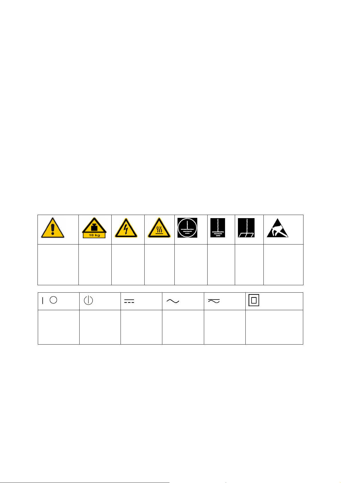
Symbols and safety labels
Notice, general
danger location
Observe product
documentation
ON/OFF supply
voltage
Caution
when
handling
heavy
equipment
Standby
indication
Danger of
electric
shock
Direct current
(DC)
Warning!
Hot surface
Alternating current
(AC)
PE terminal Ground Ground
terminal
Direct/alternating
current (DC/AC)
Device fully protected by
double (reinforced) insulation
Be careful when
handling
electrostatic
sensitive
devices
1171.0000.42-05.00 Page 1
Page 4

Basic Safety Instructions
Tags and their meaning
The following signal words are used in the product documentation in order to warn the reader about risks
and dangers.
indicates a hazardous situation which, if not avoided, will result in death or
serious injury.
indicates a hazardous situation which, if not avoided, could result in death or
serious injury.
indicates a hazardous situation which, if not avoided, could result in minor or
moderate injury.
indicates the possibility of incorrect operation which can result in damage to
the product.
In the product documentation, the word ATTENTION is used synonymously.
These tags are in accordance with the standard definition for civil applications in the European Economic
Area. Definitions that deviate from the standard definition may also exist in other economic areas or
military applications. It is therefore essential to make sure that the tags described here are always used
only in connection with the related product documentation and the related product. The use of tags in
connection with unrelated products or documentation can result in misinterpretation and in personal injury
or material damage.
Operating states and operating positions
The product may be operated only under the operating conditions and in the positions specified by the
manufacturer, without the product's ventilation being obstructed. If the manufacturer's specifications are
not observed, this can result in electric shock, fire and/or serious personal injury or death. Applicable local
or national safety regulations and rules for the prevention of accidents must be observed in all work
performed.
1. Unless otherwise specified, the following requirements apply to Rohde & Schwarz products:
predefined operating position is always with the housing floor facing down, IP protection 2X, pollution
severity 2, overvoltage category 2, use only indoors, max. operating altitude 2000 m above sea level,
max. transport altitude 4500 m above sea level. A tolerance of ±10 % shall apply to the nominal
voltage and ±5 % to the nominal frequency.
2. Do not place the product on surfaces, vehicles, cabinets or tables that for reasons of weight or stability
are unsuitable for this purpose. Always follow the manufacturer's installation instructions when
installing the product and fastening it to objects or structures (e.g. walls and shelves). An installation
that is not carried out as described in the product documentation could result in personal injury or
death.
3. Do not place the product on heat-generating devices such as radiators or fan heaters. The ambient
temperature must not exceed the maximum temperature specified in the product documentation or in
the data sheet. Product overheating can cause electric shock, fire and/or serious personal injury or
death.
1171.0000.42-05.00 Page 2
Page 5

Basic Safety Instructions
Electrical safety
If the information on electrical safety is not observed either at all to the extent necessary, electric shock,
fire and/or serious personal injury or death may occur.
1. Prior to switching on the product, always ensure that the nominal voltage setting on the product
matches the nominal voltage of the AC supply network. If a different voltage is to be set, the power
use of the product may have to be changed accordingly.
f
2. In the case of products of safety class I with movable power cord and connector, operation is
permitted only on sockets with an earthing contact and protective earth connection.
3. Intentionally breaking the protective earth connection either in the feed line or in the product itself is
not permitted. Doing so can result in the danger of an electric shock from the product. If extension
cords or connector strips are implemented, they must be checked on a regular basis to ensure that
they are safe to use.
4. If the product does not have a power switch for disconnection from the AC supply network, the plug of
the connecting cable is regarded as the disconnecting device. In such cases, always ensure that the
power plug is easily reachable and accessible at all times (corresponding to the length of connecting
cable, approx. 2 m). Functional or electronic switches are not suitable for providing disconnection from
the AC supply network. If products without power switches are integrated into racks or systems, a
disconnecting device must be provided at the system level.
5. Never use the product if the power cable is damaged. Check the power cable on a regular basis to
ensure that it is in proper operating condition. By taking appropriate safety measures and carefully
laying the power cable, you can ensure that the cable will not be damaged and that no one can be
hurt by, for example, tripping over the cable or suffering an electric shock.
6. The product may be operated only from TN/TT supply networks fused with max. 16 A (higher fuse
only after consulting with the Rohde & Schwarz group of companies).
7. Do not insert the plug into sockets that are dusty or dirty. Insert the plug firmly and all the way into the
socket. Otherwise, sparks that result in fire and/or injuries may occur.
8. Do not overload any sockets, extension cords or connector strips; doing so can cause fire or electric
shocks.
9. For measurements in circuits with voltages V
> 30 V, suitable measures (e.g. appropriate
rms
measuring equipment, fusing, current limiting, electrical separation, insulation) should be taken to
avoid any hazards.
10. Ensure that the connections with information technology equipment, e.g. PCs or other industrial
computers, comply with the IEC60950-1/EN60950-1 or IEC61010-1/EN 61010-1 standards that apply
in each case.
11. Unless expressly permitted, never remove the cover or any part of the housing while the product is in
operation. Doing so will expose circuits and components and can lead to injuries, fire or damage to the
product.
12. If a product is to be permanently installed, the connection between the PE terminal on site and the
product's PE conductor must be made first before any other connection is made. The product may be
installed and connected only by a licensed electrician.
13. For permanently installed equipment without built-in fuses, circuit breakers or similar protective
devices, the supply circuit must be fused in such a way that anyone who has access to the product, as
well as the product itself, is adequately protected from injury or damage.
1171.0000.42-05.00 Page 3
Page 6

Basic Safety Instructions
14. Use suitable overvoltage protection to ensure that no overvoltage (such as that caused by a bolt of
lightning) can reach the product. Otherwise, the person operating the product will be exposed to the
danger of an electric shock.
15. Any object that is not designed to be placed in the openings of the housing must not be used for this
purpose. Doing so can cause short circuits inside the product and/or electric shocks, fire or injuries.
6. Unless specified otherwise, products are not liquid-proof (see also section "Operating states and
1
operating positions", item 1. Therefore, the equipment must be protected against penetration by
liquids. If the necessary precautions are not taken, the user may suffer electric shock or the product
itself may be damaged, which can also lead to personal injury.
17. Never use the product under conditions in which condensation has formed or can form in or on the
product, e.g. if the product has been moved from a cold to a warm environment. Penetration by water
increases the risk of electric shock.
18. Prior to cleaning the product, disconnect it completely from the power supply (e.g. AC supply network
or battery). Use a soft, non-linting cloth to clean the product. Never use chemical cleaning agents such
as alcohol, acetone or diluents for cellulose lacquers.
Operation
1. Operating the products requires special training and intense concentration. Make sure that persons
who use the products are physically, mentally and emotionally fit enough to do so; otherwise, injuries
or material damage may occur. It is the responsibility of the employer/operator to select suitable
personnel for operating the products.
2. Before you move or transport the product, read and observe the section titled "Transport".
3. As with all industrially manufactured goods, the use of substances that induce an allergic reaction
(allergens) such as nickel cannot be generally excluded. If you develop an allergic reaction (such as a
skin rash, frequent sneezing, red eyes or respiratory difficulties) when using a Rohde & Schwarz
product, consult a physician immediately to determine the cause and to prevent health problems or
stress.
4. Before you start processing the product mechanically and/or thermally, or before you take it apart, be
sure to read and pay special attention to the section titled "Waste disposal", item 1.
5. Depending on the function, certain products such as RF radio equipment can produce an elevated
level of electromagnetic radiation. Considering that unborn babies require increased protection,
pregnant women must be protected by appropriate measures. Persons with pacemakers may also be
exposed to risks from electromagnetic radiation. The employer/operator must evaluate workplaces
where there is a special risk of exposure to radiation and, if necessary, take measures to avert the
potential danger.
6. Should a fire occur, the product may release hazardous substances (gases, fluids, etc.) that can
cause health problems. Therefore, suitable measures must be taken, e.g. protective masks and
protective clothing must be worn.
7. If a laser product (e.g. a CD/DVD drive) is integrated into a Rohde & Schwarz product, absolutely no
other settings or functions may be used as described in the product documentation. The objective is to
prevent personal injury (e.g. due to laser beams).
1171.0000.42-05.00 Page 4
Page 7

Basic Safety Instructions
Repair and service
1. The product may be opened only by authorized, specially trained personnel. Before any work is
performed on the product or before the product is opened, it must be disconnected from the AC supply
network. Otherwise, personnel will be exposed to the risk of an electric shock.
2. Adjustments, replacement of parts, maintenance and repair may be performed only by electrical
xperts authorized by Rohde & Schwarz. Only original parts may be used for replacing parts relevant
e
to safety (e.g. power switches, power transformers, fuses). A safety test must always be performed
after parts relevant to safety have been replaced (visual inspection, PE conductor test, insulation
resistance measurement, leakage current measurement, functional test). This helps ensure the
continued safety of the product.
Batteries and rechargeable batteries/cells
If the information regarding batteries and rechargeable batteries/cells is not observed either at all or to the
extent necessary, product users may be exposed to the risk of explosions, fire and/or serious personal
injury, and, in some cases, death. Batteries and rechargeable batteries with alkaline electrolytes (e.g.
lithium cells) must be handled in accordance with the EN 62133 standard.
1. Cells must not be taken apart or crushed.
2. Cells or batteries must not be exposed to heat or fire. Storage in direct sunlight must be avoided.
Keep cells and batteries clean and dry. Clean soiled connectors using a dry, clean cloth.
3. Cells or batteries must not be short-circuited. Cells or batteries must not be stored in a box or in a
drawer where they can short-circuit each other, or where they can be short-circuited by other
conductive materials. Cells and batteries must not be removed from their original packaging until they
are ready to be used.
4. Keep cells and batteries out of the hands of children. If a cell or a battery has been swallowed, seek
medical aid immediately.
5. Cells and batteries must not be exposed to any mechanical shocks that are stronger than permitted.
6. If a cell develops a leak, the fluid must not be allowed to come into contact with the skin or eyes. If
contact occurs, wash the affected area with plenty of water and seek medical aid.
7. Improperly replacing or charging cells or batteries that contain alkaline electrolytes (e.g. lithium cells)
can cause explosions. Replace cells or batteries only with the matching Rohde & Schwarz type (see
parts list) in order to ensure the safety of the product.
8. Cells and batteries must be recycled and kept separate from residual waste. Rechargeable batteries
and normal batteries that contain lead, mercury or cadmium are hazardous waste. Observe the
national regulations regarding waste disposal and recycling.
Transport
1. The product may be very heavy. Therefore, the product must be handled with care. In some cases,
the user may require a suitable means of lifting or moving the product (e.g. with a lift-truck) to avoid
back or other physical injuries.
1171.0000.42-05.00 Page 5
Page 8

Informaciones elementales de seguridad
2. Handles on the products are designed exclusively to enable personnel to transport the product. It is
therefore not permissible to use handles to fasten the product to or on transport equipment such as
cranes, fork lifts, wagons, etc. The user is responsible for securely fastening the products to or on the
means of transport or lifting. Observe the safety regulations of the manufacturer of the means of
transport or lifting. Noncompliance can result in personal injury or material damage.
3. If you use the product in a vehicle, it is the sole responsibility of the driver to drive the vehicle safely
and properly. The manufacturer assumes no responsibility for accidents or collisions. Never use the
product in a moving vehicle if doing so could distract the driver of the vehicle. Adequately secure the
product in the vehicle to prevent injuries or other damage in the event of an accident.
Waste disposal
1. If products or their components are mechanically and/or thermally processed in a manner that goes
beyond their intended use, hazardous substances (heavy-metal dust such as lead, beryllium, nickel)
may be released. For this reason, the product may only be disassembled by specially trained
personnel. Improper disassembly may be hazardous to your health. National waste disposal
regulations must be observed.
2. If handling the product releases hazardous substances or fuels that must be disposed of in a special
way, e.g. coolants or engine oils that must be replenished regularly, the safety instructions of the
manufacturer of the hazardous substances or fuels and the applicable regional waste disposal
regulations must be observed. Also observe the relevant safety instructions in the product
documentation. The improper disposal of hazardous substances or fuels can cause health problems
and lead to environmental damage.
Informaciones elementales de seguridad
Es imprescindible leer y observar las siguientes instrucciones e informaciones de seguridad!
El principio del grupo de empresas Rohde & Schwarz consiste en tener nuestros productos siempre al día
con los estándares de seguridad y de ofrecer a nuestros clientes el máximo grado de seguridad. Nuestros
productos y todos los equipos adicionales son siempre fabricados y examinados según las normas de
seguridad vigentes. Nuestro sistema de garantía de calidad controla constantemente que sean cumplidas
estas normas. El presente producto ha sido fabricado y examinado según el certificado de conformidad
adjunto de la UE y ha salido de nuestra planta en estado impecable según los estándares técnicos de
seguridad. Para poder preservar este estado y garantizar un funcionamiento libre de peligros, el usuario
deberá atenerse a todas las indicaciones, informaciones de seguridad y notas de alerta. El grupo de
empresas Rohde & Schwarz está siempre a su disposición en caso de que tengan preguntas referentes a
estas informaciones de seguridad.
Además queda en la responsabilidad del usuario utilizar el producto en la forma debida. Este producto
está destinado exclusivamente al uso en la industria y el laboratorio o, si ha sido expresamente
autorizado, para aplicaciones de campo y de ninguna manera deberá ser utilizado de modo que alguna
persona/cosa pueda sufrir daño. El uso del producto fuera de sus fines definidos o sin tener en cuenta las
instrucciones del fabricante queda en la responsabilidad del usuario. El fabricante no se hace en ninguna
forma responsable de consecuencias a causa del mal uso del producto.
1171.0000.42-05.00 Page 6
Page 9
Informaciones elementales de seguridad
Se parte del uso correcto del producto para los fines definidos si el producto es utilizado conforme a las
indicaciones de la correspondiente documentación del producto y dentro del margen de rendimiento
definido (ver hoja de datos, documentación, informaciones de seguridad que siguen). El uso del producto
hace necesarios conocimientos técnicos y ciertos conocimientos del idioma inglés. Por eso se debe tener
en cuenta que el producto solo pueda ser operado por personal especializado o personas instruidas en
profundidad con las capacidades correspondientes. Si fuera necesaria indumentaria de seguridad para el
so de productos de Rohde & Schwarz, encontraría la información debida en la documentación del
u
producto en el capítulo correspondiente. Guarde bien las informaciones de seguridad elementales, así
como la documentación del producto, y entréguelas a usuarios posteriores.
Tener en cuenta las informaciones de seguridad sirve para evitar en lo posible lesiones o daños por
peligros de toda clase. Por eso es imprescindible leer detalladamente y comprender por completo las
siguientes informaciones de seguridad antes de usar el producto, y respetarlas durante el uso del
producto. Deberán tenerse en cuenta todas las demás informaciones de seguridad, como p. ej. las
referentes a la protección de personas, que encontrarán en el capítulo correspondiente de la
documentación del producto y que también son de obligado cumplimiento. En las presentes
informaciones de seguridad se recogen todos los objetos que distribuye el grupo de empresas
Rohde & Schwarz bajo la denominación de "producto", entre ellos también aparatos, instalaciones así
como toda clase de accesorios.
Símbolos y definiciones de seguridad
Aviso: punto de
peligro general
Observar la
documentación
del producto
Tensión de
alimentación de
PUESTA EN
MARCHA /
PARADA
Atención en
el manejo de
dispositivos
de peso
elevado
Indicación de
estado de
espera
(Standby)
Peligro de
choque
eléctrico
Corriente
continua (DC)
Advertencia:
superficie
caliente
Conexión a
conductor de
protección
Corriente alterna
(AC)
Conexión
a tierra
Corriente
continua /
Corriente alterna
(DC/AC)
Conexión
a masa
El aparato está protegido
en su totalidad por un
aislamiento doble
(reforzado)
Aviso: Cuidado
en el manejo de
dispositivos
sensibles a la
electrostática
(ESD)
1171.0000.42-05.00 Page 7
Page 10

Informaciones elementales de seguridad
Palabras de señal y su significado
En la documentación del producto se utilizan las siguientes palabras de señal con el fin de advertir contra
riesgos y peligros.
PELIGRO identifica un peligro inminente con riesgo elevado que
provocará muerte o lesiones graves si no se evita.
ADVERTENCIA identifica un posible peligro con riesgo medio de
provocar muerte o lesiones (graves) si no se evita.
ATENCIÓN identifica un peligro con riesgo reducido de provocar
lesiones leves o moderadas si no se evita.
AVISO indica la posibilidad de utilizar mal el producto y, como
consecuencia, dañarlo.
En la documentación del producto se emplea de forma sinónima el
término CUIDADO.
Las palabras de señal corresponden a la definición habitual para aplicaciones civiles en el área
económica europea. Pueden existir definiciones diferentes a esta definición en otras áreas económicas o
en aplicaciones militares. Por eso se deberá tener en cuenta que las palabras de señal aquí descritas
sean utilizadas siempre solamente en combinación con la correspondiente documentación del producto y
solamente en combinación con el producto correspondiente. La utilización de las palabras de señal en
combinación con productos o documentaciones que no les correspondan puede llevar a interpretaciones
equivocadas y tener por consecuencia daños en personas u objetos.
Estados operativos y posiciones de funcionamiento
El producto solamente debe ser utilizado según lo indicado por el fabricante respecto a los estados
operativos y posiciones de funcionamiento sin que se obstruya la ventilación. Si no se siguen las
indicaciones del fabricante, pueden producirse choques eléctricos, incendios y/o lesiones graves con
posible consecuencia de muerte. En todos los trabajos deberán ser tenidas en cuenta las normas
nacionales y locales de seguridad del trabajo y de prevención de accidentes.
1. Si no se convino de otra manera, es para los productos Rohde & Schwarz válido lo que sigue:
como posición de funcionamiento se define por principio la posición con el suelo de la caja para
abajo, modo de protección IP 2X, grado de suciedad 2, categoría de sobrecarga eléctrica 2, uso
solamente en estancias interiores, utilización hasta 2000 m sobre el nivel del mar, transporte hasta
4500 m sobre el nivel del mar. Se aplicará una tolerancia de ±10 % sobre el voltaje nominal y de
±5 % sobre la frecuencia nominal.
2. No sitúe el producto encima de superficies, vehículos, estantes o mesas, que por sus características
de peso o de estabilidad no sean aptos para él. Siga siempre las instrucciones de instalación del
fabricante cuando instale y asegure el producto en objetos o estructuras (p. ej. paredes y estantes). Si
se realiza la instalación de modo distinto al indicado en la documentación del producto, pueden
causarse lesiones o incluso la muerte.
3. No ponga el producto sobre aparatos que generen calor (p. ej. radiadores o calefactores). La
temperatura ambiente no debe superar la temperatura máxima especificada en la documentación del
producto o en la hoja de datos. En caso de sobrecalentamiento del producto, pueden producirse
choques eléctricos, incendios y/o lesiones graves con posible consecuencia de muerte.
1171.0000.42-05.00 Page 8
Page 11

Informaciones elementales de seguridad
Seguridad eléctrica
Si no se siguen (o se siguen de modo insuficiente) las indicaciones del fabricante en cuanto a seguridad
eléctrica, pueden producirse choques eléctricos, incendios y/o lesiones graves con posible consecuencia
de muerte.
1. Antes de la puesta en marcha del producto se deberá comprobar siempre que la tensión
reseleccionada en el producto coincida con la de la red de alimentación eléctrica. Si es necesario
p
modificar el ajuste de tensión, también se deberán cambiar en caso dado los fusibles
correspondientes del producto.
2. Los productos de la clase de protección I con alimentación móvil y enchufe individual solamente
podrán enchufarse a tomas de corriente con contacto de seguridad y con conductor de protección
conectado.
3. Queda prohibida la interrupción intencionada del conductor de protección, tanto en la toma de
corriente como en el mismo producto. La interrupción puede tener como consecuencia el riesgo de
que el producto sea fuente de choques eléctricos. Si se utilizan cables alargadores o regletas de
enchufe, deberá garantizarse la realización de un examen regular de los mismos en cuanto a su
estado técnico de seguridad.
4. Si el producto no está equipado con un interruptor para desconectarlo de la red, se deberá considerar
el enchufe del cable de conexión como interruptor. En estos casos se deberá asegurar que el enchufe
siempre sea de fácil acceso (de acuerdo con la longitud del cable de conexión, aproximadamente
2 m). Los interruptores de función o electrónicos no son aptos para el corte de la red eléctrica. Si los
productos sin interruptor están integrados en bastidores o instalaciones, se deberá colocar el
interruptor en el nivel de la instalación.
5. No utilice nunca el producto si está dañado el cable de conexión a red. Compruebe regularmente el
correcto estado de los cables de conexión a red. Asegúrese, mediante las medidas de protección y
de instalación adecuadas, de que el cable de conexión a red no pueda ser dañado o de que nadie
pueda ser dañado por él, p. ej. al tropezar o por un choque eléctrico.
6. Solamente está permitido el funcionamiento en redes de alimentación TN/TT aseguradas con fusibles
de 16 A como máximo (utilización de fusibles de mayor amperaje solo previa consulta con el grupo de
empresas Rohde & Schwarz).
7. Nunca conecte el enchufe en tomas de corriente sucias o llenas de polvo. Introduzca el enchufe por
completo y fuertemente en la toma de corriente. La no observación de estas medidas puede provocar
chispas, fuego y/o lesiones.
8. No sobrecargue las tomas de corriente, los cables alargadores o las regletas de enchufe ya que esto
podría causar fuego o choques eléctricos.
9. En las mediciones en circuitos de corriente con una tensión U
> 30 V se deberán tomar las medidas
eff
apropiadas para impedir cualquier peligro (p. ej. medios de medición adecuados, seguros, limitación
de tensión, corte protector, aislamiento etc.).
10. Para la conexión con dispositivos informáticos como un PC o un ordenador industrial, debe
comprobarse que éstos cumplan los estándares IEC60950-1/EN60950-1 o IEC61010-1/EN 61010-1
válidos en cada caso.
11. A menos que esté permitido expresamente, no retire nunca la tapa ni componentes de la carcasa
mientras el producto esté en servicio. Esto pone a descubierto los cables y componentes eléctricos y
puede causar lesiones, fuego o daños en el producto.
1171.0000.42-05.00 Page 9
Page 12

Informaciones elementales de seguridad
12. Si un producto se instala en un lugar fijo, se deberá primero conectar el conductor de protección fijo
con el conductor de protección del producto antes de hacer cualquier otra conexión. La instalación y
la conexión deberán ser efectuadas por un electricista especializado.
13. En el caso de dispositivos fijos que no estén provistos de fusibles, interruptor automático ni otros
mecanismos de seguridad similares, el circuito de alimentación debe estar protegido de modo que
todas las personas que puedan acceder al producto, así como el producto mismo, estén a salvo de
posibles daños.
14. Todo producto debe estar protegido contra sobretensión (debida p. ej. a una caída del rayo) mediante
los correspondientes sistemas de protección. Si no, el personal que lo utilice quedará expuesto al
peligro de choque eléctrico.
15. No debe introducirse en los orificios de la caja del aparato ningún objeto que no esté destinado a ello.
Esto puede producir cortocircuitos en el producto y/o puede causar choques eléctricos, fuego o
lesiones.
16. Salvo indicación contraria, los productos no están impermeabilizados (ver también el capítulo
"Estados operativos y posiciones de funcionamiento", punto 1). Por eso es necesario tomar las
medidas necesarias para evitar la entrada de líquidos. En caso contrario, existe peligro de choque
eléctrico para el usuario o de daños en el producto, que también pueden redundar en peligro para las
personas.
17. No utilice el producto en condiciones en las que pueda producirse o ya se hayan producido
condensaciones sobre el producto o en el interior de éste, como p. ej. al desplazarlo de un lugar frío a
otro caliente. La entrada de agua aumenta el riesgo de choque eléctrico.
18. Antes de la limpieza, desconecte por completo el producto de la alimentación de tensión (p. ej. red de
alimentación o batería). Realice la limpieza de los aparatos con un paño suave, que no se deshilache.
No utilice bajo ningún concepto productos de limpieza químicos como alcohol, acetona o diluyentes
para lacas nitrocelulósicas.
Funcionamiento
1. El uso del producto requiere instrucciones especiales y una alta concentración durante el manejo.
Debe asegurarse que las personas que manejen el producto estén a la altura de los requerimientos
necesarios en cuanto a aptitudes físicas, psíquicas y emocionales, ya que de otra manera no se
pueden excluir lesiones o daños de objetos. El empresario u operador es responsable de seleccionar
el personal usuario apto para el manejo del producto.
2. Antes de desplazar o transportar el producto, lea y tenga en cuenta el capítulo "Transporte".
3. Como con todo producto de fabricación industrial no puede quedar excluida en general la posibilidad
de que se produzcan alergias provocadas por algunos materiales empleados, los llamados alérgenos
(p. ej. el níquel). Si durante el manejo de productos Rohde & Schwarz se producen reacciones
alérgicas, como p. ej. irritaciones cutáneas, estornudos continuos, enrojecimiento de la conjuntiva o
dificultades respiratorias, debe avisarse inmediatamente a un médico para investigar las causas y
evitar cualquier molestia o daño a la salud.
4. Antes de la manipulación mecánica y/o térmica o el desmontaje del producto, debe tenerse en cuenta
imprescindiblemente el capítulo "Eliminación", punto 1.
1171.0000.42-05.00 Page 10
Page 13

Informaciones elementales de seguridad
5. Ciertos productos, como p. ej. las instalaciones de radiocomunicación RF, pueden a causa de su
función natural, emitir una radiación electromagnética aumentada. Deben tomarse todas las medidas
necesarias para la protección de las mujeres embarazadas. También las personas con marcapasos
pueden correr peligro a causa de la radiación electromagnética. El empresario/operador tiene la
obligación de evaluar y señalizar las áreas de trabajo en las que exista un riesgo elevado de
exposición a radiaciones.
6. Tenga en cuenta que en caso de incendio pueden desprenderse del producto sustancias tóxicas
(gases, líquidos etc.) que pueden generar daños a la salud. Por eso, en caso de incendio deben
usarse medidas adecuadas, como p. ej. máscaras antigás e indumentaria de protección.
7. En caso de que un producto Rohde & Schwarz contenga un producto láser (p. ej. un lector de
CD/DVD), no debe usarse ninguna otra configuración o función aparte de las descritas en la
documentación del producto, a fin de evitar lesiones (p. ej. debidas a irradiación láser).
Reparación y mantenimiento
1. El producto solamente debe ser abierto por personal especializado con autorización para ello. Antes
de manipular el producto o abrirlo, es obligatorio desconectarlo de la tensión de alimentación, para
evitar toda posibilidad de choque eléctrico.
2. El ajuste, el cambio de partes, el mantenimiento y la reparación deberán ser efectuadas solamente
por electricistas autorizados por Rohde & Schwarz. Si se reponen partes con importancia para los
aspectos de seguridad (p. ej. el enchufe, los transformadores o los fusibles), solamente podrán ser
sustituidos por partes originales. Después de cada cambio de partes relevantes para la seguridad
deberá realizarse un control de seguridad (control a primera vista, control del conductor de
protección, medición de resistencia de aislamiento, medición de la corriente de fuga, control de
funcionamiento). Con esto queda garantizada la seguridad del producto.
Baterías y acumuladores o celdas
Si no se siguen (o se siguen de modo insuficiente) las indicaciones en cuanto a las baterías y
acumuladores o celdas, pueden producirse explosiones, incendios y/o lesiones graves con posible
consecuencia de muerte. El manejo de baterías y acumuladores con electrolitos alcalinos (p. ej. celdas de
litio) debe seguir el estándar EN 62133.
1. No deben desmontarse, abrirse ni triturarse las celdas.
2. Las celdas o baterías no deben someterse a calor ni fuego. Debe evitarse el almacenamiento a la luz
directa del sol. Las celdas y baterías deben mantenerse limpias y secas. Limpiar las conexiones
sucias con un paño seco y limpio.
3. Las celdas o baterías no deben cortocircuitarse. Es peligroso almacenar las celdas o baterías en
estuches o cajones en cuyo interior puedan cortocircuitarse por contacto recíproco o por contacto con
otros materiales conductores. No deben extraerse las celdas o baterías de sus embalajes originales
hasta el momento en que vayan a utilizarse.
4. Mantener baterías y celdas fuera del alcance de los niños. En caso de ingestión de una celda o
batería, avisar inmediatamente a un médico.
5. Las celdas o baterías no deben someterse a impactos mecánicos fuertes indebidos.
1171.0000.42-05.00 Page 11
Page 14

Informaciones elementales de seguridad
6. En caso de falta de estanqueidad de una celda, el líquido vertido no debe entrar en contacto con la
piel ni los ojos. Si se produce contacto, lavar con agua abundante la zona afectada y avisar a un
médico.
7. En caso de cambio o recarga inadecuados, las celdas o baterías que contienen electrolitos alcalinos
(p. ej. las celdas de litio) pueden explotar. Para garantizar la seguridad del producto, las celdas o
baterías solo deben ser sustituidas por el tipo Rohde & Schwarz correspondiente (ver lista de
recambios).
8. Las baterías y celdas deben reciclarse y no deben tirarse a la basura doméstica. Las baterías o
acumuladores que contienen plomo, mercurio o cadmio deben tratarse como residuos especiales.
Respete en esta relación las normas nacionales de eliminación y reciclaje.
Transporte
1. El producto puede tener un peso elevado. Por eso es necesario desplazarlo o transportarlo con
precaución y, si es necesario, usando un sistema de elevación adecuado (p. ej. una carretilla
elevadora), a fin de evitar lesiones en la espalda u otros daños personales.
2. Las asas instaladas en los productos sirven solamente de ayuda para el transporte del producto por
personas. Por eso no está permitido utilizar las asas para la sujeción en o sobre medios de transporte
como p. ej. grúas, carretillas elevadoras de horquilla, carros etc. Es responsabilidad suya fijar los
productos de manera segura a los medios de transporte o elevación. Para evitar daños personales o
daños en el producto, siga las instrucciones de seguridad del fabricante del medio de transporte o
elevación utilizado.
3. Si se utiliza el producto dentro de un vehículo, recae de manera exclusiva en el conductor la
responsabilidad de conducir el vehículo de manera segura y adecuada. El fabricante no asumirá
ninguna responsabilidad por accidentes o colisiones. No utilice nunca el producto dentro de un
vehículo en movimiento si esto pudiera distraer al conductor. Asegure el producto dentro del vehículo
debidamente para evitar, en caso de un accidente, lesiones u otra clase de daños.
Eliminación
1. Si se trabaja de manera mecánica y/o térmica cualquier producto o componente más allá del
funcionamiento previsto, pueden liberarse sustancias peligrosas (polvos con contenido de metales
pesados como p. ej. plomo, berilio o níquel). Por eso el producto solo debe ser desmontado por
personal especializado con formación adecuada. Un desmontaje inadecuado puede ocasionar daños
para la salud. Se deben tener en cuenta las directivas nacionales referentes a la eliminación de
residuos.
2. En caso de que durante el trato del producto se formen sustancias peligrosas o combustibles que
deban tratarse como residuos especiales (p. ej. refrigerantes o aceites de motor con intervalos de
cambio definidos), deben tenerse en cuenta las indicaciones de seguridad del fabricante de dichas
sustancias y las normas regionales de eliminación de residuos. Tenga en cuenta también en caso
necesario las indicaciones de seguridad especiales contenidas en la documentación del producto. La
eliminación incorrecta de sustancias peligrosas o combustibles puede causar daños a la salud o
daños al medio ambiente.
1171.0000.42-05.00 Page 12
Page 15

R&S®EM100 Content
1 Content
1 CONTENT 15
2 QUALITY CERTIFICATE 19
3 CE CERTIFICATE 20
4 SUPPORT CENTER ADDRESS 21
5 FUNCTIONING OF THE R&S®EM100 22
6 INITIAL OPERATION 27
Front view 27
Rear view 27
Unpacking the instrument 27
Switching the monitoring receiver on and off 29
Ambient and operating conditions 29
Preventive maintenance 29
Connectors on the monitoring receiver 30
The R&S®EM100 has the following connectors: 30
Description and configuration of the connectors 33
Setting up a connection with hyperterminal or telnet 35
Setting the TCP parameters 37
Firmware update 40
6.1.2 Preparations for updating the firmware 40
6.1.3 Firmware Update with the Firmware Upgrade Tool 41
6.1.4 Firmware Update with the SD Card 42
6.1.5 Option code activation 43
7 TROUBLESHOOTING 44
8 SCPI INTERFACE 45
Document Outline 45
8.1.1 List of figures 46
8.1.2 List of tables 47
8.1.3 List of commands 49
User Manual R&S® EM100 - 31 EN 15
Page 16

R&S®EM100 Content
Conventions Used in the Documentation 61
8.1.4
9 SCPI COMMANDS 62
SCPI Introduction 62
9.1.1 Common Command Structure 63
9.1.2 Device-Specific Command Structure 63
9.1.3 Structure of a Command Line 65
9.1.4 Responses to Queries 66
9.1.5 Parameters 66
Status Reporting 69
9.1.6 Structure of an SCPI Status Register 69
9.1.7 Description of the Status Registers 73
9.1.8 Use of the Status Reporting System 79
9.1.9 Resetting Values of the Status Reporting System 80
Error Messages 81
Commands Description 84
9.1.10 Notation 84
9.1.11 Unprotected commands 85
9.1.12 Errors 85
9.1.13 Common Commands 86
10 INSTRUMENT BEHAVIOUR 89
Error Situations 89
Ranging and Rounding 89
Value Representation 90
Default Values 90
Instrument States 90
10.1.1 Introduction 90
10.1.2 Receiver States 90
11 COMMANDS REFERENCE 93
Common Commands 93
ABORt subsystem 93
CALCulate subsystem 94
DIAGnostic subsystem 98
DISPlay subsystem 99
FORMat subsystem 118
INITiate subsystem 122
User Manual R&S® EM100 - 31 EN 16
Page 17

R&S®EM100 Content
INPut subsystem 123
MEASure subsystem 124
MEMory subsystem 125
11.1.1 Memory list subsystem 131
11.1.2 Memory save subsystem 133
MMEMory subsystem 136
OUTPut subsystem 144
Program preset subsystem 156
ROUTe subsystem 158
Sense Subsystem 172
11.1.3 Sense Memory Scan subsystem MSC 197
11.1.4 Sense Panorama Scan subsystem PSC 206
11.1.5 Sense Frequency Scan subsystem SWE 211
STATus subsystem 219
SYSTem subsystem 224
TRACe|DATA subsystem 245
TRACe|DATA:UDP subsystem 268
TRIGger subsystem 277
GPSCompass subsystem 288
GPSCompass subsystem Data 292
12 UDP DATA STREAMS 294
Stream Packet Structure 294
Audio Streaming 297
FScan streaming 299
MScan streaming 301
CW streaming 302
IFPan streaming 302
IF streaming 304
PSCAN streaming 305
GPSCompass streaming 307
User Manual R&S® EM100 - 31 EN 17
Page 18

R&S®EM100 Content
13 DATA STRUCTURE RECORDED FILES 310
IQ record files 310
Trace record files 310
Audio record files 310
14 DEFAULT VALUES 312
CALCulation subsystem 312
DISPlay subsystem 312
FORMat subsystem 313
INPut subsystem 313
MEASurement subsystem 313
MEMory subsystem 313
OUTPut subsystem 314
SENSe subsystem 314
STATus subsystem 316
SYSTem subsystem 317
TRACe subsystem 317
15 REFERENCES 318
User Manual R&S® EM100 - 31 EN 18
Page 19

R&S®EM100 Quality Certificate
2 Quality Certificate
ear Customer,
D
Thank you for purchasing a Rohde & Schwarz product.
This product is manufactured using state-of-the-art production methods. It is developed, produced and
tested in line with the rules of our Quality Management System. The Rohde & Schwarz Quality
Management System is ISO 9001 certified.
Certified Quality System
ISO 9001
DQS REG. NO 1954-04
User Manual R&S® EM100 - 31 EN 19
Page 20
R&S®EM100 CE Certificate
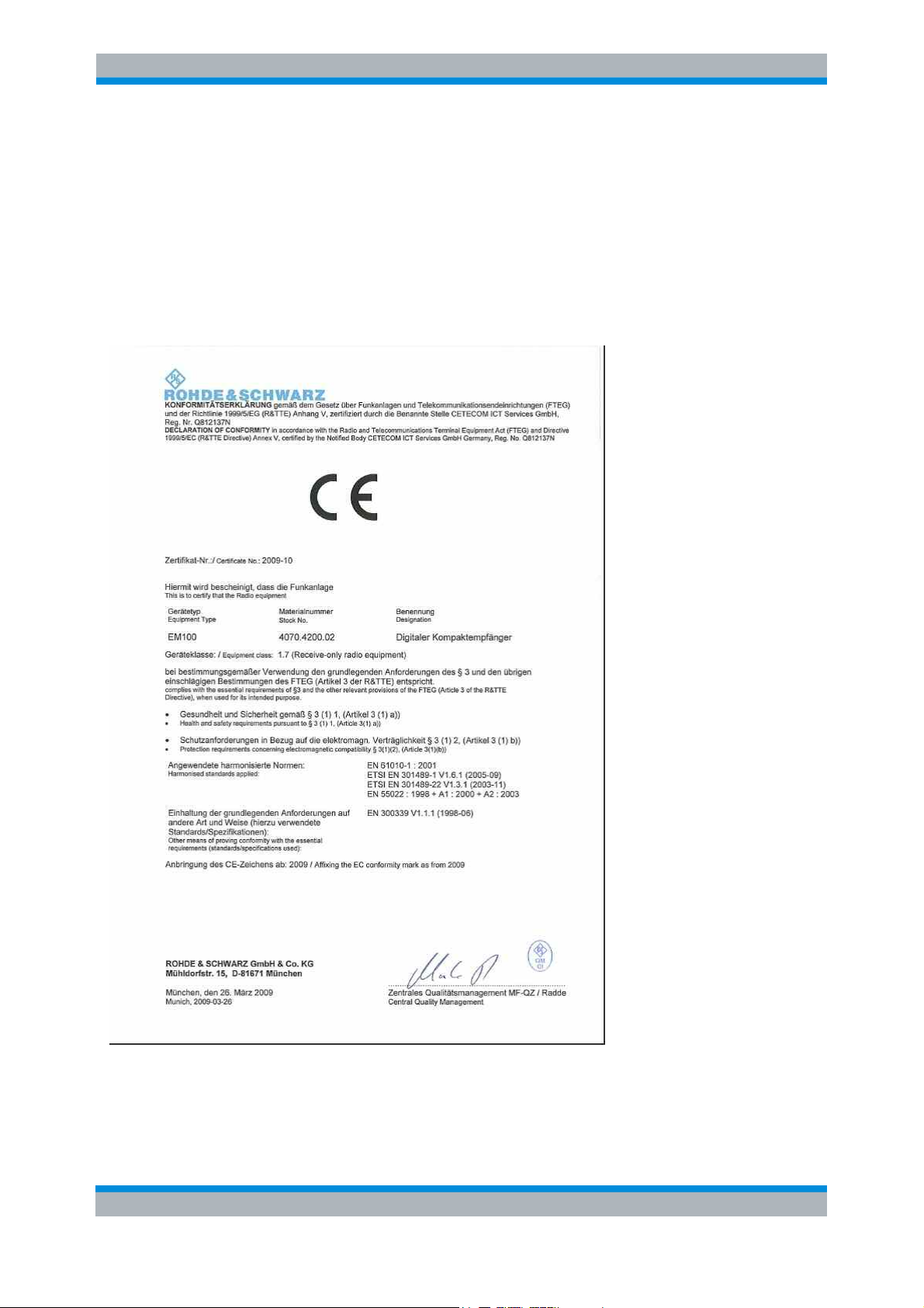
3 CE Certificate
Note:
The applicable CE standards are fulfilled only under the following operating conditions:
- The connecting cable for the DC power supply must be shorter than 3 m.
- Direct operation of the EM100 from the onboard DC power supply system of a vehicle is prohibited.
The receiver may not be operated if these conditions are not fulfilled.
User Manual R&S® EM100 - 31 EN 20
Page 21

R&S®EM100 Support Center Address
4 Support Center Address
hould you have any questions regarding this Rohde & Schwarz instrument, please call our support
S
center hotline at Rohde & Schwarz Vertriebs-GmbH.
Our team will be happy to answer your questions and work with you to find a solution.
The hotline is open Monday to Friday between 8 a.m. and 5 p.m (Central European Time).
Should you wish to contact us outside normal business hours, please leave a voice message or send
us a fax or email. We will contact you as soon as possible.
If you would like to receive information on modifications and updates for a specific instrument, please
send us a short email stating which instrument. We will ensure that you regularly receive the latest
information.
Support Center
Tel: +49 180 512 42 42
Fax: +49 89 41 29 137 77
Email: CustomerSupport@rohde-schwarz.com
User Manual R&S® EM100 - 31 EN 21
Page 22
R&S®EM100 Functioning of the R&S®EM100
5 Functioning of the R&S®EM100
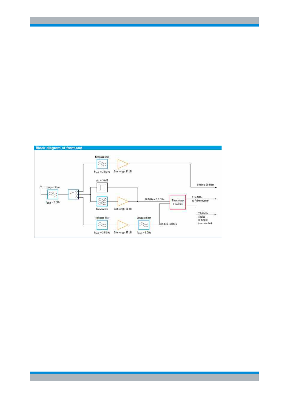
Frontend
Starting from the antenna socket, the frequency in the signal path is limited to 8 GHz. Signal
processing then takes place in three paths for three different frequency ranges. Signals from 9 kHz to
30 MHz are routed via a preamplifier directly to the A/D converter. Signals from 20 MHz to 3.5 GHz
are taken to the IF section via a preselection and a preamplifier, or via an attenuator pad in the case of
high signal levels. The preselection as well as the attenuator pad effectively protect the IF section
against overloading. This is particularly important in this frequency range, where the maximum signal
sum levels occur. Signals from 3.5 GHz to 8 GHz are taken to the IF section via a preamplifier. The
three-stage IF section processes the signals from 20 MHz to 8 GHz for the subsequent A/D converter.
To provide optimum instrument performance, only signals up to 7.5 GHz are processed in the
subsequent stages. The uncontrolled 21.4 MHz IF can also be tapped ahead of the A/D converter via
a BNC socket of the R&S®EM100 for further external processing.
Fig. 5-1: Block diagram, frontend
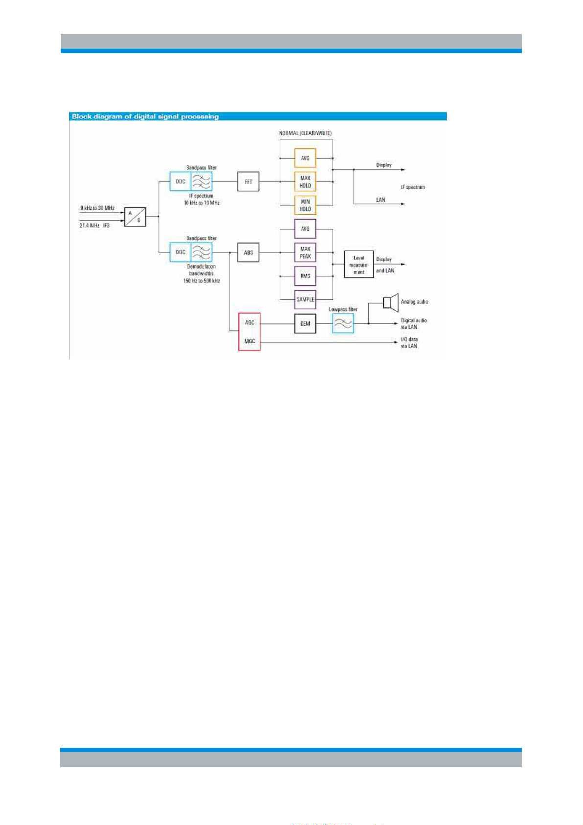
Digital signal processing
Following A/D conversion of the received signal, the signal path splits: The IF spectrum is computed
via a digital downconverter (DDC), a digital bandpass filter and the FFT block. The user can set the
bandwidth of the bandpass filter in a range from 1 kHz to 10 MHz. Before the IF spectrum is output on
the display or via the LAN interface, results are postprocessed by means of the AVERAGE, MIN
HOLD or MAX HOLD function as selected by the user. The second DDC and bandpass filter are used
to prepare the signal for level measurement or demodulation. To process the different signals with
optimum signal-to-noise ratio, the receiver contains IF filters with demodulation bandwidths from
150 Hz to 500 kHz, which can be selected independently of the IF bandwidth.
Prior to the level measurement, the absolute value of the level is determined and weighted by means
of the AVERAGE, MAX PEAK, RMS or SAMPLE function, as selected by the user. Next, the
measured level is output via the display or the LAN interface. For the demodulation of analog signals,
the complex baseband data is subjected to automatic gain control (AGC) or manual gain control
(MGC) after the bandpass filter. It is then applied to the AM, FM, USB, LSB, ISB, pulse or CW
demodulation stage. The complex baseband data (I/Q data) representing the digitized signal is output
directly following the AGC/MGC block via the LAN interface.
User Manual R&S® EM100 - 31 EN 22
Page 23
R&S®EM100 Functioning of the R&S®EM100
The results that are obtained are available in digital format and can be output as required via the LAN
interface. Digital audio data are reconverted to analog signals for output via the loudspeaker.
Fig. 5-2: Block diagram, digital signal processing
High receiver sensitivity, high signal resolution
The R&S®EM100 features an IF bandwidth of up to 10 MHz. This allows even very short signal pulses
to be captured since the receiver displays the large bandwidth of 10 MHz in a single spectrum about
the set center frequency without any scanning being required. The widest IF bandwidth of 10 MHz
yields the widest spectral display; the narrowest IF bandwidth of 1 kHz yields maximum sensitivity.
The IF spectrum is digitally calculated by means of a fast Fourier transform (FFT). Usage of FFTs in
the IF stage has a significant benefit: Significantly more sensitive and higher-resolution reception
compared to conventional analog receivers with the same spectral bandwidth.
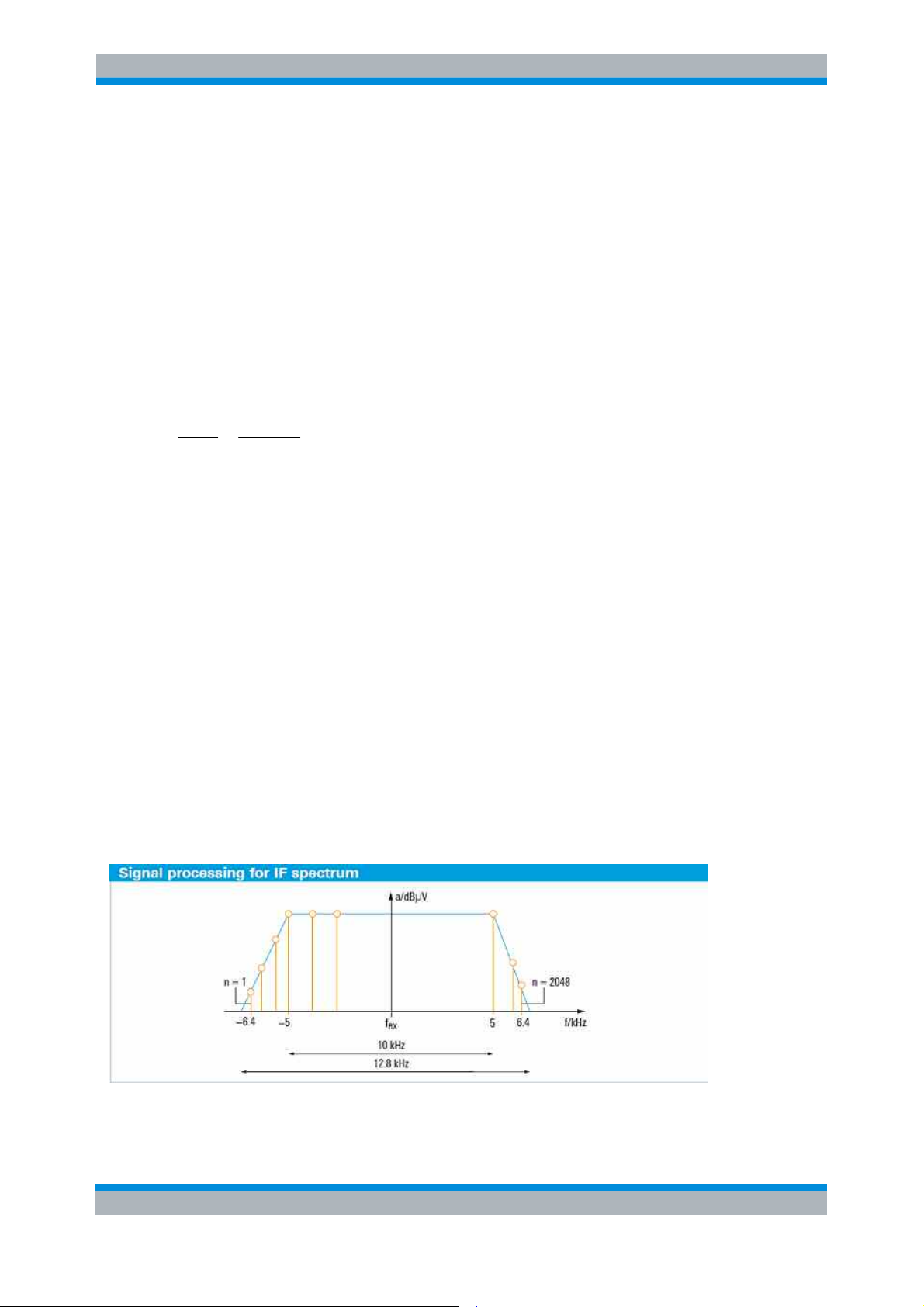
IF spectrum
For example, if the setting B
IF spectrum
= 10 kHz is chosen for sensitive signal reception, the following
steps will occur schematically in the FFT computation of the IF spectrum: Due to the finite edge
steepness of the IF filter, the sampling rate f
bandwidth B
IF spectrum
. The quotient of the sampling rate and the IF bandwidth is thus a value > 1 and is
must be greater than the selected IF spectrum
S
a measure of the edge steepness of the IF filter.
This relationship is expressed by the following two formulas:
User Manual R&S® EM100 - 31 EN 23
Page 24
R&S®EM100 Functioning of the R&S®EM100
2048
2048
f
s
B
SpectrumIF
=
const
or
constBf
=
*
SpectrumIFs
The value of the constant is dependent on the selected IF bandwidth, i.e. it may vary as a function of
the IF bandwidth. For an IF bandwidth of
B
F spectrum
I
wide, a sampling rate of f
= 10 kHz, this constant is equal to 1.28. In order to display an IF spectrum that is 10 kHz
= 12.8 kHz is thus required. The R&S®EM100 uses a standard FFT length
S
N of 2048 points to generate the IF spectrum. To calculate these points, the 12.8 kHz sampling band
in the above example is divided into 2048 equidistant frequency slices, which are also referred to as
bins (see figure "Signal processing for IF spectrum"). The bandwidth BW
of the frequency slices is
bin
obtained as follows:
BW
Bin
f
S
8,12
kHz
Hz
25,6
===
This means that in the above example only the calculated bandwidth of 6.25 Hz for each bin has to be
taken into account as the noise bandwidth in the calculation of the displayed average noise floor
(DANL) in accordance with the formula below (the effect of the window function (Blackman window) of
the FFT is not considered here for simplicity's sake):
DANL = –174 dBm + NF + 10 · log(BW
bin
/Hz)
The quantity NF represents the overall noise figure of the receiver. The above example shows that,
due to the use of the FFT, the actual resolution bandwidth (RBW) to be taken into account in DANL
calculation is clearly smaller (i.e. BW
) than would be expected for the wide display range of 10 kHz.
bin
Another advantage of the high spectral resolution used in the FFT calculation is that signals located
close together (e.g. f
, f2, f3) can be captured and represented in the IF spectrum as discrete signals
1
(see figure "Signal display in IF spectrum"). If, comparable to the operation of an analog receiver, a
resolution bandwidth equal to
the set IF bandwidth was selected (RBW = BWIF spectrum),
a sum signal f
discrete signals f
would be displayed instead of the three
Sum
, f2and f3.
1
Fig. 5-3: Actual sampling bandwidth compared with selected IF bandwidth
User Manual R&S® EM100 - 31 EN 24
Page 25
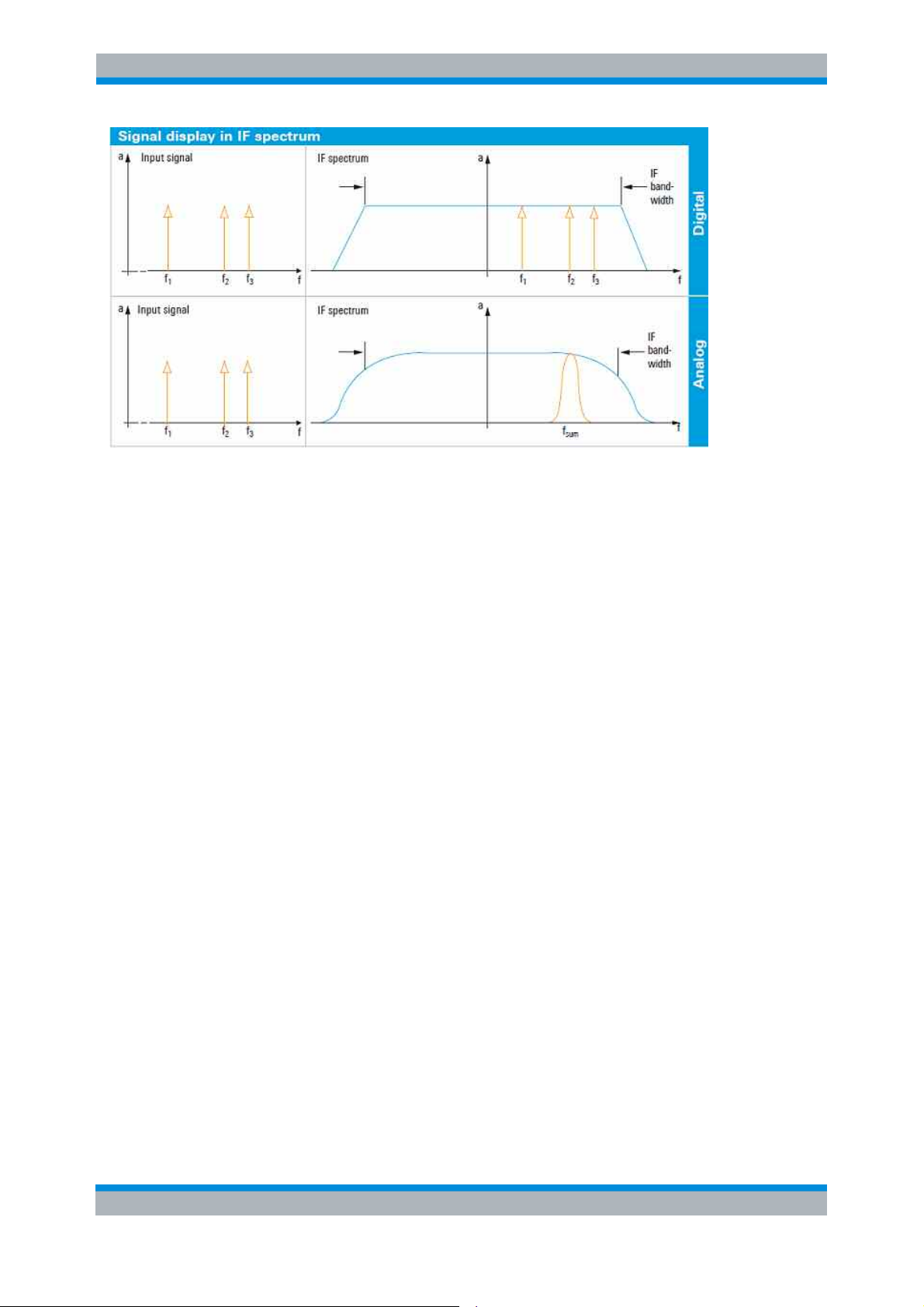
R&S®EM100 Functioning of the R&S®EM100
Fig. 5-4: Signal resolution in the IF spectrum with digital and analog receiver concept
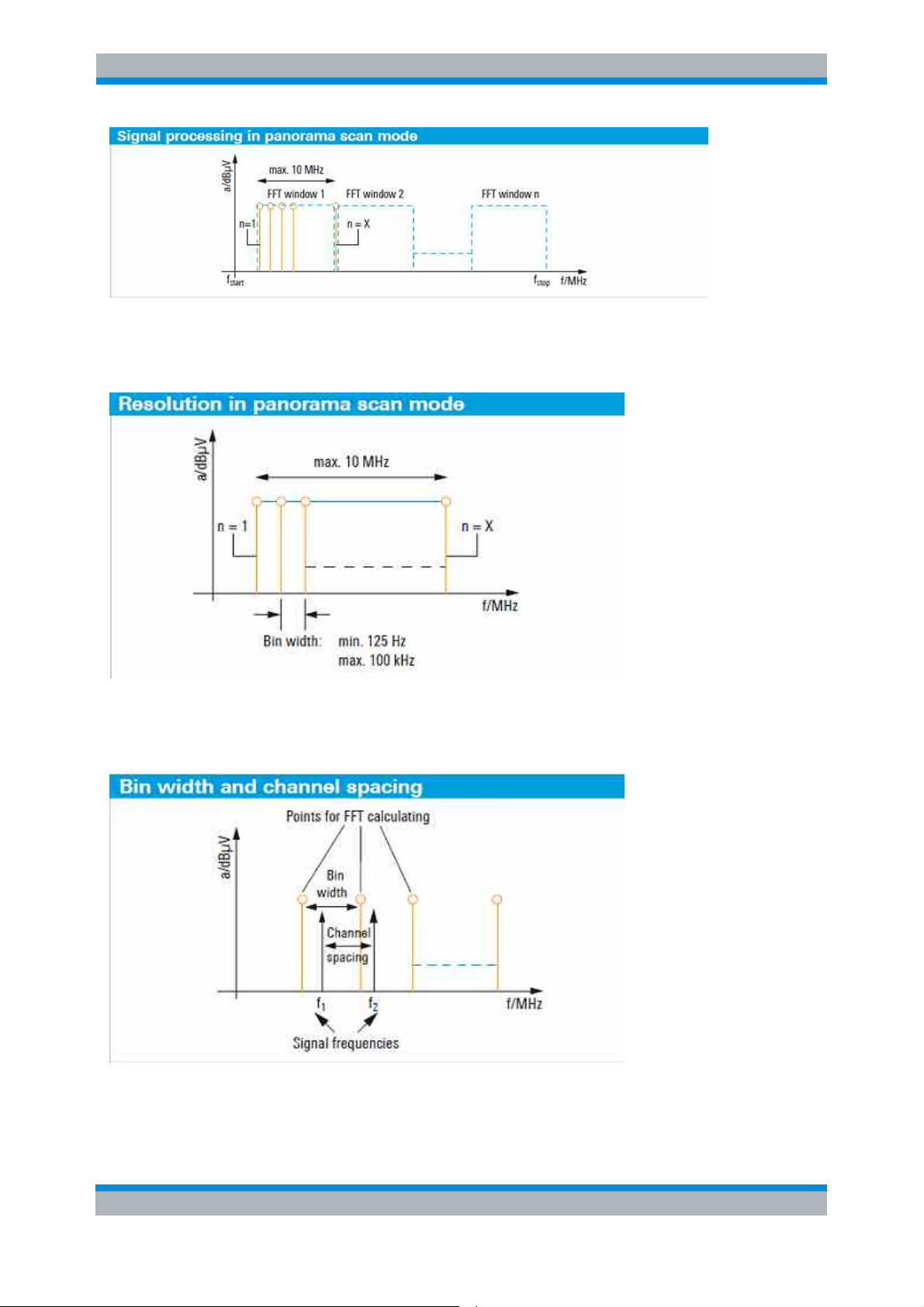
Panorama scan
The receiver's maximum FFT bandwidth of 10 MHz makes it possible to perform extremely fast scans
across a wide frequency range (panorama scan). For this purpose, frequency windows of max.
10 MHz width are linked in succession, and thus the complete, predefined scan range is traversed
(see figure "Signal processing in panorama scan mode"). Analogous to the IF spectrum, an FFT is
used to process the broad window with a finer resolution. The width of the frequency window and the
FFT length (number of FFT points) are variable and are selected by the receiver. In the panorama
scan mode, the user can select among 12 resolution bandwidths from 125 Hz to 100 kHz. The
resolution bandwidth corresponds to the width of the frequency slices (bin width) mentioned under "IF
spectrum" above. Based on the selected bin width and the start and stop frequency, the R&S®EM100
automatically determines the required FFT length and the width of the frequency windows for each
scan step. The receiver selects these internal parameters so that the optimum scan speed is achieved
for each resolution bandwidth (see figure "Resolution in panorama scan mode").
In the panorama scan mode, the resolution bandwidth of 100 kHz yields the maximum scan speed,
while the resolution bandwidth of 125 Hz yields maximum sensitivity. The resolution bandwidth (bin
width) for the panorama scan (selectable between 125 Hz and 100 kHz) therefore corresponds to the
resolution bandwidth (BWbin) used in the DANL calculation for the IF spectrum (see DANL formula
under "IF spectrum" above), and can thus be used for calculating the DANL for the panorama scan.
Moreover, the user selects the resolution bandwidth to obtain the desired frequency resolution (see
figure "Bin width and channel spacing").
User Manual R&S® EM100 - 31 EN 25
Page 26
R&S®EM100 Functioning of the R&S®EM100
Fig. 5-5: Basic sequence of steps in fast panorama scan mode
Fig. 5-6: Selection of resolution for panorama scan by varying the bin width
Fig. 5-7: Selection of 12.5 kHz bin width to capture a radio service using 12.5 kHz channel spacing
User Manual R&S® EM100 - 31 EN 26
Page 27
R&S®EM100 Initial Operation
6 Initial Operation
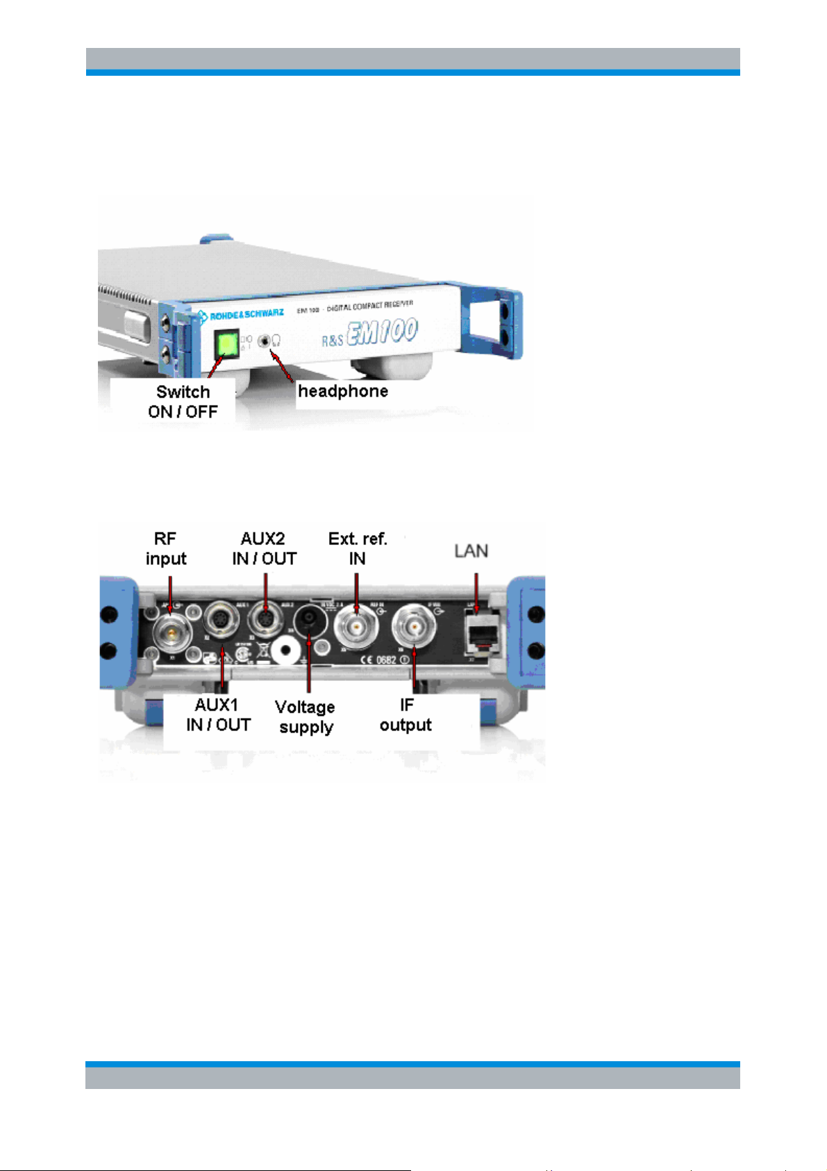
Front view
Rear view
The following section describes how to set up the instrument and how to connect external devices
including the power supply.
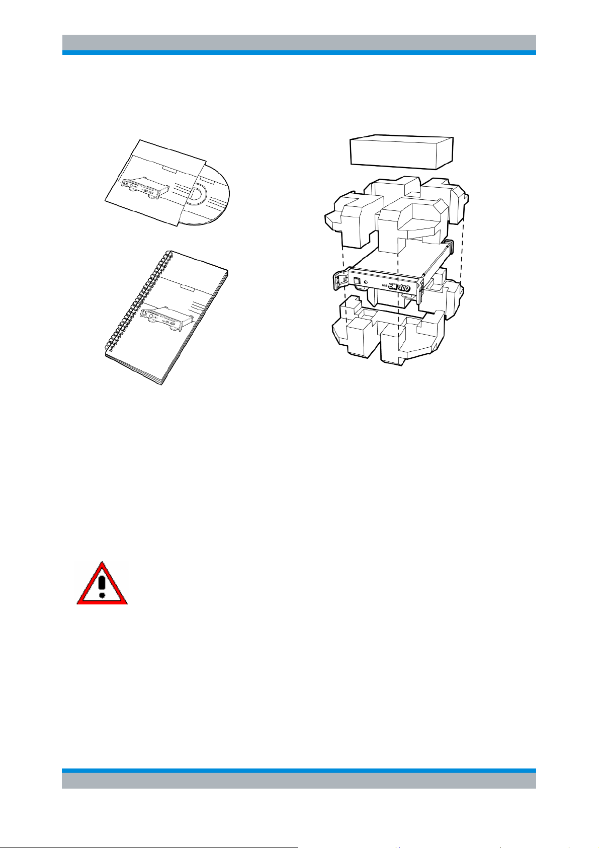
Unpacking the instrument
The R&SEM100 is shipped in an outer box with form-fitted packaging consisting of a top shell and a
bottom shell.
All of the supplied accessories are contained in the package.
R To unpack the instrument, remove the top shell and the accessory box.
User Manual R&S® EM100 - 31 EN 27
Page 28
R&S®EM100 Initial Operation
roper adapter to the power supply
permissible temperature range from 0°C to 45°C. Outside of this temperature
R Remove the R&S®EM100 and accessories.
Setting up the instrument
The R&S®EM100 digital compact receiver is designed for desktop operation, built-in installation or
vehicle-based operation.
When used as a desktop instrument, the R&S®EM100 can either be placed flat on the table, or the
folding support feet on the bottom can be opened to incline the instrument for easier usage.
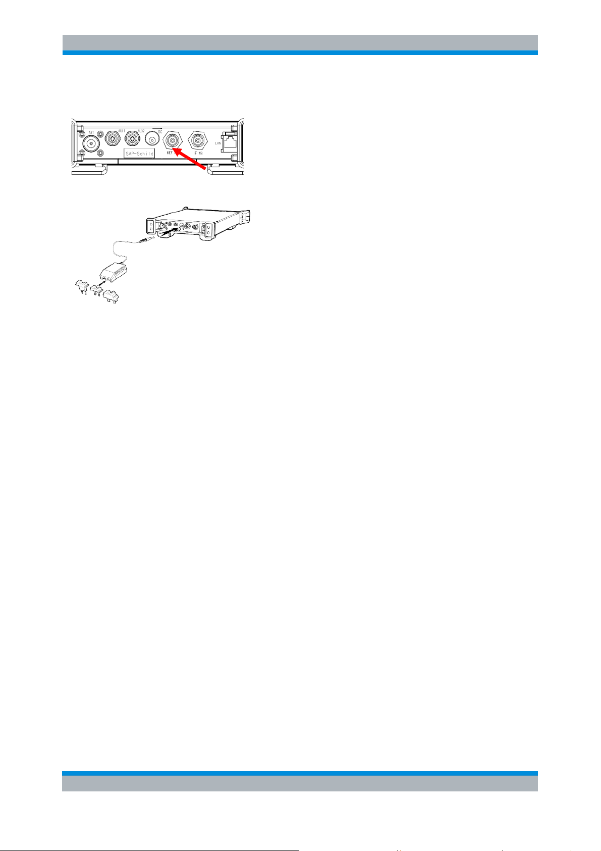
Connecting to the power supply
The R&S®EM100 can be operated using the R&S®HA-Z201 power supply (not included).
Caution!
For operation from AC power, the R&S® HA-Z201 power supply (order
number 1309.6100.00) is recommended.
Prior to usage, ensure that the AC voltage corresponds to the voltage
indicated on the power supply. Attach the p
before plugging it into the AC power.
The R&S® HA-Z201 power supply may be operated only within its
range, an external DC power supply must be used.
The external DC power supply must comply with
IEC / EN / UL / CSA 60950-1 or
IEC / EN / UL / CSA 61010 -1 (applicable current versions).
Insert the power supply's jack plug into voltage supply connector X4 on the rear of the instrument until
it locks in. Then connect the adaptor to the AC power socket.
The adapter voltage range is 100 V to 240 V AC / 50 Hz to 60 Hz.
User Manual R&S® EM100 - 31 EN 28
Page 29
R&S®EM100 Initial Operation
The DC supply range for the R&S®EM100 is equal to +15 V DC +/-10 %, max. 2 A.
Plug the power supply (R&S® HA-Z201) as shown above into the R&S®EM100.
Switching the monitoring receiver on and off
Press the white button to the left on the front panel to switch on the R&S®EM100.
The on/off button will be backlit in green when the R&S®EM100 is switched on.
When switching off the instrument or when interrupting the supply voltage, please keep in mind that
the internal storage system in the EM100 (flash memory) is transaction-safe (i.e. it always retains its
consistency when switched off), but the SD card is not. Accordingly, the file system on the SD card
can become unusable if the receiver is switched off during an SD write procedure or is disconnected
from the supply voltage.
Moreover, the receiver must NEVER be switched off during a firmware update.
Ambient and operating conditions
Reliable operation of the R&S®EM100 is ensured under the following ambient and operating
conditions:
Air humidity max. 95 %
Nominal operating altitude max. 4,600 m above sea level
Transport elevation max. 12,000 m above sea level
Overvoltage category 2
Pollution severity 2
Preventive maintenance
If the R&S®EM100 becomes soiled, clean it with a moist, soft cloth and a mild cleaning agent.
User Manual R&S® EM100 - 31 EN 29
Page 30
R&S®EM100 Initial Operation
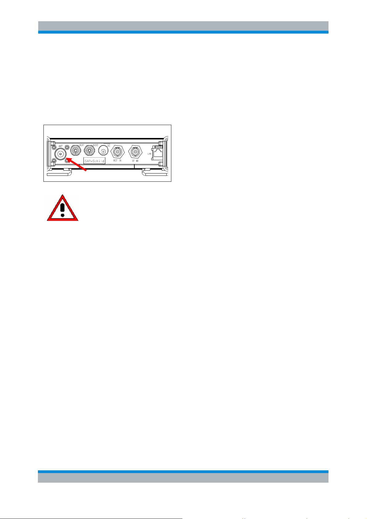
Connectors on the monitoring receiver
The R&S®EM100 has the following connectors:
RF input
Connect the RF input to the antenna using a cable with an N connector.
Make sure that the input is not overloaded.
Caution!
The maximum permissible continuous
power level to the RF input is +20 dBm
(100 mW)
The maximum permissible DC voltage at
the RF input is 0 VDC.
User Manual R&S® EM100 - 31 EN 30
Page 31

R&S®EM100 Initial Operation
Headphone connector
A 3.5 mm stereo connector is provided for headphones on the front panel. The internal impedance of the
connector is approx. 100 Ohm.
AUX1 IN/OUT
External control signals can be fed to the receiver via the AUX1 input/output, for example.
AUX2 IN/OUT
Control signals for externally triggered test procedures (e.g. for coverage measurement applications) are supplied
to the receiver via the AUX2 input/output.
External reference input
A 10 MHz reference signal for frequency synchronization is supplied via the BNC socket labeled EXT REF. The
level of the reference signal must be greater than 0 dBm.
IF output
The uncontrolled 21.4 MHz IF signal is provided for external use via the BNC socket labeled IF OUT.
User Manual R&S® EM100 - 31 EN 31
Page 32

R&S®EM100 Initial Operation
LAN interface
A 10/100 BaseT LAN interface is provided for remote operation of the receiver.
To comply with the EMC directive (R&TTE), only
LAN cables having a length less than 3 m may
be used (see recommended accessories).
User Manual R&S® EM100 - 31 EN 32
Page 33

R&S®EM100 Initial Operation
Description and configuration of the connectors
Voltage supply
15 V DC +/- 10 %, max. 2 A
DC coaxial connector on receiver, plus voltage on inner pin
Suitable plug JSBP5 (external Ø 6.5 mm, internal Ø 4.3 mm, pin Ø 1.4 mm, shaft length 9.5
mm)
DC cable length < 3 m
Direct operation from the onboard DC power supply system of a vehicle is prohibited.
Associated SCPI commands:
Query battery or AC power DIAGnostic[:SERVice]:ADAPter[:STATe]?
RF input
N female
Max. +20 dBm / 100 mW
No DC component allowed
10 dB attenuator pad (from 20 MHz to 3.5 GHz) can be enabled
...................................... 98
Associated SCPI commands :
Switch attenuator pad on/off INPut:ATTenuation:STATe<Boolean>
Headphone connector
3.5 mm stereo connector (female)
Impedance approx. 100 Ohm
Associated SCPI commands :
Audio mute SYSTem:AUDio:VOLume MINimum
AUX1/AUX2 input and output
7-pin connector (female) with screw fitting.
A suitable male connector can be purchased using the R&S® order number 1145.5921.00.
The pins for the AUX connectors are numbered as follows:
....................................... 123
......................................... 228
Fig. 6-1: Pin numbers for the AUX connectors (view of R&S EM100 connector)
User Manual R&S® EM100 - 31 EN 33
Page 34

R&S®EM100 Initial Operation
The AUX pins are assigned as follows:
Pin 1 2 3 4 5 6 7
AUX1
AUX2
Table 1: Pin assignments for the AUX connectors
5 V output
max. 500 mA
Output Input/Output Input/Output -- Output Input Input
5 V output
max. 500 mA
Output Output Input -- Output Input Input
I/O bit 0 I/O bit 1 GND TxD RxD Sense_in
Squelch Mute
GND TxD RxD Trigger_in
All of the inputs and outputs use TTL low levels,
i.e. low = 0 V to 0.8 V, high = 2.0 V to 3.3 V.
RXD and TXD form a RS232 connection (low level TTL). TxD is the data output from the EM100, and
RxD is the data input to the EM100.
The RS232 parameters are set by the EM100 firmware. For GPS devices (e.g. the GPS compass in
the R&S HE300 antenna), the settings are as follows: 19200 baud, even parity, 1 stop bit, 8 data bits.
External reference input
BNC female
External 10 MHz reference frequency
Level min. 0 dBm
Associated SCPI commands :
Switch reference internal/external [SENSe]:ROSCillator:SOURceINTernal|EXTernal
..................... 210
IF output
BNC female
Uncontrolled IF 21.4 MHz
Associated SCPI commands :
Switch IF output on/off
OUTPut:IF[:STATe]<Boolean>.................................................. 147
LAN interface
RJ45 female
Tolerates crosslink cables
10M/100M speed
DHCP-enabled
IP address, subnet and gateway can be set
LAN allows:
SCPI remote control
UDP data streams
Remote firmware update using update tool
Usage of the PRView software
Usage of the EM100Control remote operating software
Associated SCPI commands :
LAN settings SYSTem:COMMunicate:SOCKet:ADDRess<ip-address>
............................ 232
User Manual R&S® EM100 - 31 EN 34
Page 35

R&S®EM100 Initial Operation
SD memory card
Max. capacity 32 GB (but max. individual file size is 4 GB)
A class 6 card is needed for the internal recording option.
The card should be formatted by the EM100 for good performance.
Associated SCPI commands :
Format SD card MMEMory:INIT[<label>]
Note: The R&S®EM100 is shipped with the SD memory card installed. The enclosure must be opened
to access this card.
.................................................................... 143
Setting up a connection with hyperterminal or telnet
The R&S®EM100 uses remote control with SCPI commands via a LAN telnet connection.
The EM100 is shipped with the following factory default settings:
DHCP OFF
IP address
Subnetwork mask 255.255.255.0
172.17.75.1
Port 5555
Gateway 0.0.0.0
The hostname for the receiver is derived from the serial number as follows:
For R&S®EM100 rs-em100-<serial number>-002
Example: rs-em100-102007-002
Notes:
R If DHCP access is changed from enabled to disabled, the EM100 will switch to the IP address that
is statically configured.
R In case of a reset to the factory default settings, the current LAN settings are retained!
Setup and testing of a LAN connection between a PC and the EM100 is discussed here. This LAN
connection can be used to input all of the SCPI commands and observe the responses. UDP streams
cannot be monitored in this manner.
It is assumed here that the IP address and subnet mask are known, or DHCP is activated and the
hostname is known.
See section "Setting the TCP parameters" (p. 37) for a description of how to set these parameters in
case they are not known.
R Connect the LAN cable to the PC and the EM100 (direct connection), or connect the EM100 to the
office network (network connection). The EM100 will automatically detect crossed and uncrossed
LAN cables.
R In case of a direct connection, set the IP addresses and subnet masks for the EM100 and PC so
that a connection can be established.
R In case of a network connection, set the EM100 to DHCP and configure the DHCP server as
required, or (without DHCP) set the IP addresses and subnet masks like for a direct connection.
User Manual R&S® EM100 - 31 EN 35
Page 36

R&S®EM100 Initial Operation
R Open a DOS window and ping the EM100 as follows:
ping –a 172.17.75.1
The parameter –a returns the hostname of EM100 .
R If the connection is working, open a hyperterminal on the PC as follows:
Start-Program s-Accessories-Communication-Hyperterminal
Fig. 6-2: Hyperterminal connection setup
R In Hyperterminal, enable transmission of line ends and local echo as follows:
File – Properties – Settings – ASCII Configuration
User Manual R&S® EM100 - 31 EN 36
Page 37

R&S®EM100 Initial Operation
Fig. 6-3: Hyperterminal configuration
R In Hyperterminal, enter the SCPI command
*IDN? (+Return)
and the receiver should respond with
"Rohde&Schwarz", instrument type, serial number, firmware version.
Note: You might need to enter *IDN? several times before the receiver responds.
Fig. 6-4: Hyperterminal SCPI command
R Instead of Hyperterminal, you can also use a DOS window and open a telnet connection to the
receiver as follows:
telnet –t vt100 172.17.75.1 5555
Associated SCPI commands :
DHCP on / off SYSTem:COMMunicate:SOCKet:DHCP[:STATe]<Boolean>
...................... 233
Gateway SYSTem:COMMunicate:LAN:GATeway<ip-address>.................................. 230
Subnet mask SYSTem:COMMunicate:LAN:SUBMask<subnetmask> ............................... 231
IP adress SYSTem:COMMunicate:SOCKet:ADDRess<ip-address> ........................... 232
Port SYSTem:COMMunicate:SOCKet:PORT<numeric_value> ........................... 234
Query MAC adress SYSTem:COMMunicate:LAN:ETHernet?
...................................................... 230
Setting the TCP parameters
Method 1
Method 1 always works but requires an additional cable.
The following equipment is needed to set the IP address, subnet mask, port or DHCP setting:
A special serial cable (R&S part number 4070.4481.00) in order to connect a COM port on a
PC to the EM100. This cable converts the levels from RS232 levels to low-level TTL.
A PC or laptop with a COM port (D-Sub, 9 pins)
A terminal program on the PC, e.g. Hyperterminal; see section "Setting up a connection" (p.
35)
Notes:
1) PCs without a COM port can be connected via a USB-to-RS232 cable + R&S cable, assuming
the terminal program can be operated with COM via USB.
User Manual R&S® EM100 - 31 EN 37
Page 38

R&S®EM100 Initial Operation
2) A TCP cable can remain connected while setting the TCP parameters, but it cannot be
addressed since a TCP stack is not yet available during this time.
R Launch Hyperterminal
R In Hyperterminal, configure the RS232 connection as follows:
Fig. 5: RS232 settings for the AUX connection
R Switch off the R&S®EM100
R Connect the R&S cable via AUX2 to the R&S®EM100
R Make Hyperterminal the active window by clicking on it
(top bar blue, not gray)
R Repeatedly press the spacebar on the PC and switch on the R&S®EM100
R The following screen should appear in Hyperterminal:
User Manual R&S® EM100 - 31 EN 38
Page 39

R&S®EM100 Initial Operation
Fig. 6: Terminal with network settings
R Modify the IP address, subnet mask, port and DHCP as required
R Start the EM100 with S
R It can also be started with F, but this will delete all of the user settings.
Method 2
Method 2 presumes that the receiver can be addressed via TCP (i.e. the IP address, etc. are known).
An additional cable is not required.
R Set up a telnet connection to the receiver; see section "Setting up a connection" (p. 35).
R Enter the commands for the required changes in a single line, e.g.:
"127.10.290.11"; :SYST:COMM:LAN:SUBM "255.0.0.0"
SYST:COMM:SOCK:ADDR
Note: The reason for entering the commands in a single line is that command lines (unlike queries) are
executed as a whole; all commands in the line are either executed jointly or rejected.
Command lines for TCP modification are also executed immediately. If each TCP command is sent in
a separate line, there is the risk that the user will be blocked out of the TCP connection if the receiver
becomes inaccessible after executing the first line.
R After execution of the TCP modification, the existing TCP connection terminates because the
receiver is now accessible via the new address.
R To test this, set up a telnet connection using the new address.
User Manual R&S® EM100 - 31 EN 39
Page 40

R&S®EM100 Initial Operation
Firmware update
n order to be able to use all of the features of the R&S®EM100, it is recommended to update the
I
instrument to the latest firmware version.
The latest firmware can be downloaded from the R&S
terms EM100 firmware).
6.1.2 Preparations for updating the firmware
Interrupt any running scans
A currently running scan will significantly slow down the process of downloading the firmware files to
the SD card. Accordingly, you should interrupt it beforehand using the SCPI command ABORT or
*RST (or by switching the instrument off and back on again).
Exchange and format SD card if necessary
®
website (www.rohde-schwarz.com, search
The high recording speeds of the "Internal Recording" option necessitate the use of a high-quality,
class 6 SD card with a write speed of at least 133x / 20MB/s. A suitable card (4 GB, class 6) is
available from Rohde & Schwarz under part number 4070.4475.00.
SD cards with a size up to 32 GB can be used in the R&S®EM100.
For performance-related reasons, the card should be formatted using the SCPI command
MMEMory:INIT
(p.143).
User Manual R&S® EM100 - 31 EN 40
Page 41

R&S®EM100 Initial Operation
6.1.3 Firmware Update with the Firmware Upgrade Tool
Starting with version 1.22, the firmware is supplied in the form of individual files for the SD card (see
above) as well as an update program. The update program works well if the SD card or the whole
eceiver is inaccessible.
r
The update program makes it possible to update the firmware via LAN without direct access to the SD
card. This is especially beneficial with the R&S®EM100 since its SD card can only be accessed by
opening the enclosure.
R Prior to the update
Make sure that an SD card is inserted into the EM100. Approx. 30 MB of storage space must
be free on this card.
Set up and test a LAN connection to the EM100; see section "Setting up a connection" (p. 35).
R To perform the update, launch the update program RS_PR_MR_<identification>.exe,
e.g. RS_PR_MR_V2_10.exe
User Manual R&S® EM100 - 31 EN 41
Page 42

R&S®EM100 Initial Operation
Follow the instructions that appear on the screen.
Upon completion of the update, the following message will appear on the PC:
Notes:
The update program will not start if firmware version 1.21 (or earlier) is installed on the EM100.
Options
Existing options will be retained by the firmware update.
R Note: In case of a firmware update from versions 1.04 or 1.12 to a newer version, all of the option
codes must be entered initially.
For a description of how to enable new options which might be present for the first time in the current
firmware, see section “” (p. 43).
6.1.4 Firmware Update with the SD Card
This method works well only if the SD card is directly accessible. It is not recommended for the
R&S®EM100 since the R&S®EM100’s enclosure must be opened to access the SD card.
The firmware to be installed must first be copied to an SD card (e.g. R&S HA-Z231, order number
1309.6217.00).
The following files must be copied to the SD card:
The version numbers of the individual files (e.g. V2_00) are dependent on the current firmware
version.
User Manual R&S® EM100 - 31 EN 42
Page 43

R&S®EM100 Initial Operation
Note!
Only one file of each type may be saved in the root directory of
the SD card. The update procedure will be interrupted if two
different versions of a given file type are found.
R Switch off the instrument.
R Insert the SD card into the SD card slot on the right side.
R Start the update using the SCPI command SYSTem:FIRMware:UPDate
R Wait 5 minutes, then read out the new firmware version using the following SCPI command:
*IDN?
Caution!
THE R&S®EM100
MUST NOT BE SWITCHED OFF DURING THE FIRMWARE
UPDATE!
6.1.5 Option code activation
In the R&S®EM100, additional features can be enabled using option codes.
The following table provides a summary of the available options.
Abbre
Option
Panorama Scan PS 4071.9306.03
Internal Recording IR 4071.9358.03
Frequency Extension FE 4070.4669.03
External Triggered
Measurement
Field Strength
Measurement
GPS Data Interface GP 4071.9958.03
The installed options can be displayed via SCPI using *OPT? (p. 93) additional options can be
enabled using SYSTem:SECurity:OPTion<code> (p. 243).
viatio
ETM 4071.9458.03
FS 4071.9506.03
n
R&S®EM100
Order no.
Comment
Extends the frequency range
of the R&S®EM100 from 3.5
GHz to 7.5 GHz
User Manual R&S® EM100 - 31 EN 43
Page 44

R&S®EM100 Troubleshooting
7 Troubleshooting
ymptom: IP address changes unexpectedly.
S
ossible cause: DHCP was activated / deactivated. When DHCP is activated, the receiver obtains a
P
new IP address from the DHCP server. When DHCP is deactivated, the old static address is
reenabled.
Action: Set the desired DHCP status.
Side effects of action: None
Symptom : High load in entire network.
Possible cause: UDP stream in the EM100 was activated but the UDP sink (PC) cannot (or can no
longer) be reached. As a result, the UDP packets are broadcast via switches and routers in the entire
network, resulting in a high load.
Action: Disable the UDP stream or reenable the UDP sink.
Side effects of action: None
Symptom : Poor recording quality, missing data sets
Possible cause: SD card too slow.
Incorrect type, fragmented or not formatted in the EM100.
Action: Make sure that a class 6 SD card that handles 20 MB/s is used.
Format the card in the EM100.
Side effects of action: Formatting erases the data on the card.
All of the available remote-control commands for the R&S®EM100 (SCPI commands) are described in
detail hereafter in this manual.
The SCPI section of the manual is available exclusively in English (since English is understood
throughout the programming world).
User Manual R&S® EM100 - 31 EN 44
Page 45

R&S®EM100 SCPI Interface
8 SCPI Interface
Document Outline
The SCPI standard describes an interface with which instruments can be controlled. The idea behind
SCPI is that it should not matter what kind of instrument measures e.g. a voltage level, be it a
multimeter or a radio scanner measuring the voltage at the antenna output; the command should
always be the same. Although theoretically possible, in practice this goal in unachievable. However,
the goal of every instrument designer is to stay as close to SCPI as possible.
The goal of every instrument designer is to stay as close to SCPI as possible. In addition, the EM100
tries to be backward compatible with its predecessor, the EB200 Miniport Receiver, when possible. In
fact, this compatibility requirement outweighs the SCPI compliance requirement. Therefore, the SCPI
interface for the EM100 is defined with the following rules:
1. If an EB200 SCPI command relates to functionality that is not supported by the EM100, the
command is not supported either.
2. If a function can be done via an existing EB200 SCPI command, that command is supported.
3. If a function cannot be done via an existing EB200 SCPI command, but a suitable SCPI
compliant command is available, the SCPI compliant command is supported.
4. Otherwise, a new SCPI-like command is added, specific for the EM100.
A command is rarely useful if no data can be retrieved to monitor its effect. In SCPI, this is done via
queries. Queries can be used to retrieve the settings of an instrument. However, measurements can
consist of large sets of data. Outputting that over the SCPI interface could delay the reaction time to
commands, which is why the EM100 also offers the data in another format that can be sent via the
UDP/IP protocol .
User Manual R&S® EM100 - 31 EN 45
Page 46

R&S®EM100 SCPI Interface
8.1.1List of figures
ig. 5-1: Block diagram, frontend 22
F
Fig. 5-2: Block diagram, digital signal processing 23
Fig. 5-3: Actual sampling bandwidth compared with selected IF bandwidth 24
Fig. 5-4: Signal resolution in the IF spectrum with digital and analog receiver concept 25
Fig. 5-5: Basic sequence of steps in fast panorama scan mode 26
Fig. 5-6: Selection of resolution for panorama scan by varying the bin width 26
Fig. 5-7: Selection of 12.5 kHz bin width to capture a radio service using 12.5 kHz channel spacing 26
Fig. 6-1: Pin numbers for the AUX connectors (view of R&S EM100 connector) 33
Fig. 6-2: Hyperterminal connection setup 36
Fig. 6-3: Hyperterminal configuration 37
Fig. 6-4: Hyperterminal SCPI command 37
Fig. 5: RS232 settings for the AUX connection 38
Fig. 6: Terminal with network settings 39
Figure 9-1: Tree-Structure example of command system " SYSTem " 63
Figure 9-2: Status Register Model 70
Figure 9-3: Status Registers 73
Figure 10-1: Receiver States 91
Figure 10-2: States of Frequency Scan Mode and Memory Scan Mode 92
Figure 12-1: Payload PSCAN UDP Package 307
Figure 12-2: Antenna elevation and roll 309
Figure 13-1: Trace record file contents 310
User Manual R&S® EM100 - 31 EN 46
Page 47

R&S®EM100 SCPI Interface
8.1.2List of tables
Table 1: Pin assignments for the AUX connectors................................................................................ 34
Table 9-1: List of abbreviations ........................................................................................................... 62
Table 9-2: Special numerical values ................................................................................................... 67
Table 9-3: Syntax elements................................................................................................................. 69
Table 9-4: Bit allocation of status byte ................................................................................................ 73
Table 9-5: Bit allocation of event status register ................................................................................. 74
Table 9-6: Bit allocation of STATus:OPERation register..................................................................... 75
Table 9-7: Bit allocation of STATus:OPERation:SWEeping register .................................................. 75
Table 9-8: Bit allocation of STATus:TRACe register........................................................................... 76
Table 9-9: Bit allocation of STATus:Extension register....................................................................... 77
Table 9-10: Change bit-allocation in STATus:EXTension register...................................................... 78
Table 9-11: Bit allocation of STATus: QUEStionable register.............................................................. 79
Table 9-12: Resetting status registers.................................................................................................. 80
Table 9-13: "No Error" message .......................................................................................................... 81
Table 9-14: Command Errors............................................................................................................... 81
Table 9-15: Execution Errors................................................................................................................ 82
Table 9-16: Device Specific Errors....................................................................................................... 83
Table 9-17: Query Errors...................................................................................................................... 83
Table 9-18: Device-dependent Errors .................................................................................................. 83
Table 9-19: Unprotected Commands ................................................................................................... 85
Table 9-20: Common Commands ........................................................................................................ 86
Table 9-21: Option Identification .......................................................................................................... 87
Table 11-1: Parameters for MEMory:CONTents ............................................................................... 127
Table 11-2: Block data structure for MEMory:CONTents.................................................................. 128
Table 11-3: Output data types for SENSe::DATA? ........................................................................... 174
Table 11-4: STATus register default values ...................................................................................... 223
Table 11-5: Suppress list example .................................................................................................... 245
Table 11-6: Suppress list example, query results ............................................................................. 246
Table 11-7: output types for TRACe:DATA? ..................................................................................... 248
Table 12-1: UDP Stream Format........................................................................................................ 294
Table 12-2: UDP Stream Data Types................................................................................................ 294
Table 12-3: UDP Stream, settings for < flags>................................................................................... 295
Table 12-4: UDP Stream, End Markers.............................................................................................. 296
Table 12-5: UDP Stream, Audio Format ........................................................................................... 297
Table 12-6: UDP Stream, Audio Data Types ..................................................................................... 298
Table 12-7: UDP Stream, Demodulation Modes and Identifiers ........................................................ 299
Table 12-8: UDP Stream, Audio Data Formats.................................................................................. 299
Table 12-9: FScan UDP Format......................................................................................................... 300
Table 12-10: FScan UDP Data Types................................................................................................ 300
Table 12-11: MScan UDP Format ...................................................................................................... 301
Table 12-12: MScan UDP Data Types ............................................................................................... 301
Table 12-13: CW UDP Format ........................................................................................................... 302
Table 12-14: CW UDP Data Types ..................................................................................................... 302
Table 12-15: IFPan UDP Format......................................................................................................... 303
Table 12-16: IFPan UDP Data Types.................................................................................................. 303
Table 12-17: IF UDP Format ............................................................................................................... 304
Table 12-18: IF UDP Data Types ........................................................................................................ 304
Table 12-19: Pscan UDP Format ....................................................................................................... 305
Table 12-20: Pscan UDP Data Types ................................................................................................. 306
Table 12-21: GPSCompass stream Format: <optional header> and <trace data> ............................ 308
Table 12-22: GPSCompass stream data types optional header......................................................... 308
Table 12-23: GPSCompass stream Format: <trace data>.................................................................. 308
Table 12-24: GPSCompass sample data types .................................................................................. 308
Table 12-25: GPS Header .................................................................................................................. 309
User Manual R&S® EM100 - 31 EN 47
Page 48

R&S®EM100 SCPI Interface
Table 12-26: GPS Header data types ................................................................................................. 309
Table 13-1: WAV file structure............................................................................................................. 310
Table 13-2: WAV file timestamp structure.......................................................................................... 311
able 14-1: CALCulation default values............................................................................................. 312
T
Table 14-2: DISPlay default values .................................................................................................... 312
Table 14-3: FORMat default values ................................................................................................... 313
Table 14-4: INPut default values ........................................................................................................ 313
Table 14-5: MEASurement default values.......................................................................................... 313
Table 14-6: MEMory default values.................................................................................................... 313
Table 14-7: OUTPut default values .................................................................................................... 314
Table 14-8: SENSe default values ..................................................................................................... 314
Table 14-9: STATus default values .................................................................................................... 316
Table 14-10: SYSTem default values.................................................................................................. 317
Table 14-11: TRACe default values .................................................................................................... 317
User Manual R&S® EM100 - 31 EN 48
Page 49

R&S®EM100 SCPI Interface
8.1.3List of commands
*OPT? 93
ABORt 93
CALCulate:IFPan:AVERage:TYPEMINimum|MAXimum|SCALar|OFF 94
CALCulate:IFPan:AVERage:TYPE? 94
CALCulate:IFPan:CLEar 94
CALCulate:IFPan:MARKer:MAXimum[:PEAK 95
CALCulate:IFPan:MARKer:MAXimum:LEFT 96
CALCulate:PSCan:AVERage:TYPEMINimum|MAXimum|SCALar|OFF 96
CALCulate:IFPan:MARKer:MAXimum:RIGHt 95
CALCulate:PSCan:AVERage:TYPE? 96
CALCulate:PSCan:CLEar 96
CALCulate:PSCan:MARKer:MAXimum[:PEAK] 97
CALCulate:PSCan:MARKer:MAXimum:LEFT 97
CALCulate:PSCan:MARKer:MAXimum:RIGHt 97
DIAGnostic[:SERVice]:ADAPter[:STATe]? 98
DIAGnostic[:SERVice]:INFO:SVERsion? 98
DISPlay:BRIGhtness<numeric_value>|MINimum|MAXimum 99
DISPlay:BRIGhtness?[MINimum|MAXimum] 99
DISPlay:CMAP:DEFault 100
DISPlay:CMAPINDoor|OUTDoor|BW 100
DISPlay:CMAP? 101
DISPlay:DATE:FORMatDDMMyyyy|MMDDyyyy 101
DISPlay:DATE:FORMat? 101
DISPlay:FSTRength<Boolean> 102
DISPlay:FSTRength? 102
DISPlay:IFPan:LEVel:AUTO 103
DISPlay:IFPan:LEVel:RANGe<numeric_value>|MINimum|MAXimum 103
DISPlay:IFPan:LEVel:RANGe?[MINimum|MAXimum] 104
DISPlay:IFPan:LEVel:REFerence<numeric_value>|MINimum|MAXimum 104
DISPlay:IFPan:LEVel:REFerence?[MINimum|MAXimum] 105
DISPlay:LEVel:AUTO 105
DISPlay:LEVel:LIMit:MINimum<numeric_value>|MINimum|MAXimum 106
User Manual R&S® EM100 - 31 EN 49
Page 50

R&S®EM100 SCPI Interface
DISPlay:LEVel:LIMit:MINimum?[MINimum|MAXimum] 106
DISPlay:LEVel:RANGe<numeric_value>|MINimum|MAXimum 107
DISPlay:LEVel:RANGe?[MINimum|MAXimum] 107
DISPlay:PSCan:LEVel:AUTO 108
DISPlay:PSCan:LEVel:RANGe<numeric_value>|MINimum|MAXimum 108
DISPlay:PSCan:LEVel:RANGe?[MINimum|MAXimum] 109
DISPlay:PSCan:LEVel:REFerence<numeric_value>|MINimum|MAXimum 109
DISPlay:PSCan:LEVel:REFerence?[MINimum|MAXimum] 110
DISPlay:WATerfall:CMAP<color_map> 110
DISPlay:WATerfall:CMAP? 111
DISPlay:WATerfall:CMAP:CATalog? 111
DISPlay:WATerfall:CMAP:RANGe<numeric_value>|MINimum|MAXimum 112
DISPlay:WATerfall:CMAP:RANGe?[MINimum|MAXimum] 112
DISPlay:WATerfall:CMAP:THReshold<numeric_value>|MINimum|MAXimum 113
DISPlay:WATerfall:CMAP:THReshold?[MINimum|MAXimum] 113
DISPlay:WATerfall:HOLD[:STATe]<Boolean> 114
DISPlay:WATerfall:HOLD[:STATe]? 114
DISPlay:WATerfall:SPEed<numeric_value>|MINimum|MAXimum 115
DISPlay:WATerfall:SPEed?[MINimum|MAXimum] 115
DISPlay:WINDow<display> 115
DISPlay:WINDow? 116
DISPlay:WINDow:CATalog? 116
DISPlay:WINDow:FETch? 117
DISPlay:WINDow:STORe<file_name> 117
FORMat:BORDerNORMal|SWAPped 118
FORMat:BORDer? 118
FORMat[:DATA]ASCii|PACKed[,length] 119
FORMat[:DATA]? 119
FORMat:MEMoryASCii|PACKed 120
FORMat:MEMory? 120
FORMat:SREGister ASCii|BINary|HEXadecimal|OCTal 121
FORMat:SREGister? 121
INITiate[:IMMediate] 122
INITiate:CONM[:IMMediate] 122
INPut:ATTenuation:STATe <Boolean> 123
User Manual R&S® EM100 - 31 EN 50
Page 51

R&S®EM100 SCPI Interface
INPut:ATTenuation:STATe? 123
MEASure:MODE CONTinuous|PERiodic 124
MEASure:MODE? 124
MEASure:TIME <numeric_value>|MINimum|MAXimum|DEFault 124
MEASure:TIME?[MINimum|MAXimum] 125
MEMory:CLEar<mem_loc>[,<count>|MAXimum] 126
MEMory:CONFig:CATalog? 126
MEMory:CONFig<block_data> 126
MEMory:CONFig? 127
MEMory:CONTents<mem_loc>,<mem_paras>|<packed_struct> 127
MEMory:CONTents?<mem_loc> 128
MEMory:CONTents:MPAR<mem_loc>,<Boolean> 129
MEMory:CONTents:MPAR?<mem_loc> 129
MEMory:COPY<src_loc>,<dest_loc> 130
MEMory:EXCHange<mem_loc1>,<mem_loc2> 130
MEMory:LABel<mem_loc>,<String> 130
MEMory:LABel?<mem_loc> 131
MEMory:LIST:CONTents?<index> 132
MEMory:LIST:MEMory?<mem_loc> 132
MEMory:LIST:SORT<order> 132
MEMory:SAVE:AUTO:STARt<mem_loc> 133
MEMory:SAVE:AUTO:STARt? 133
MEMory:SAVE:AUTO:STOP<mem_loc> 134
MEMory:SAVE:AUTO:STOP? 134
MEMory:SAVE:DIRect:STARt<mem_loc> 135
MEMory:SAVE:DIRect:STARt? 135
MEMory:SAVE:DIRect:STOP<mem_loc> 135
MEMory:SAVE:DIRect:STOP? 136
MMEMory:CATalog? 136
MMEMory:CATalog:DIRectories? 137
MMEMory:CDIRectory<folder_name> 138
MMEMory:CDIRectory? 138
MMEMory:COPY<src_name>,<dest_name> 139
MMEMory:DATA<file_name>,<block_data> 139
MMEMory:DATA?<file_name> 139
User Manual R&S® EM100 - 31 EN 51
Page 52

R&S®EM100 SCPI Interface
MMEMory:DELete<name> 140
MMEMory:FILE<file_name>,<block_data> 140
MMEMory:FILE?<file_name> 140
MMEMory:FILE:DATE<file_name>,<year>,<month>,<day> 141
MMEMory:FILE:DATE?<file_name> 141
MMEMory:FILE:TIME<file_name>,<hours>,<minutes>,<seconds> 142
MMEMory:FILE:TIME?<file_name> 142
MMEMory:INIT[<label>] 143
MMEMory:MDIRectory<folder_name> 143
MMEMory:MOVE<src_name>,<dest_name> 143
MMEMory:RDIRectory<folder_name> 144
OUTPut:AUX:AUTO<Boolean> 144
OUTPut:AUX:AUTO? 144
OUTPut:BITaux[<numeric_suffix>][:STATe]<Boolean> 145
OUTPut:BITaux[<numeric_suffix>][:STATe]? 145
OUTPut:BYTaux[:STATe]<numeric_value> 146
OUTPut:BYTaux[:STATe]? 146
OUTPut:IF[:STATe]<Boolean> 147
OUTPut:IF[:STATe]? 147
OUTPut:SQUelch:CONTrolMEMory|NONE 148
OUTPut:SQUelch:CONTrol? 148
OUTPut:SQUelch[:STATe]<Boolean> 148
OUTPut:SQUelch[:STATe]? 149
OUTPut:SQUelch:THReshold[:UPPer]<numeric_value>|UP|DOWN|MINimum|MAXimum 149
OUTPut:SQUelch:THReshold[:UPPer]?[MINimum|MAXimum] 150
OUTPut:SQUelch:THReshold[:UPPer]:STEP[:INCRement]<numeric_value>|MINimum|MAXimum150
OUTPut:SQUelch:THReshold[:UPPer]:STEP[:INCRement]?[MINimum|MAXimum] 151
OUTPut:TONE:CONTrol ONLY|WITHaf 151
OUTPut:TONE:CONTrol? 152
OUTPut:TONE:GAIN<numeric_value>|MINimum|MAXimum|UP|DOWN 152
OUTPut:TONE:GAIN?[MINimum|MAXimum] 153
OUTPut:TONE[:STATe]<Boolean> 153
OUTPut:TONE[:STATe]? 154
OUTPut:TONE:THReshold<numeric_value>|UP|DOWN|MINimum|MAXimum 154
OUTPut:TONE:THReshold?[MINimum|MAXimum] 155
User Manual R&S® EM100 - 31 EN 52
Page 53

R&S®EM100 SCPI Interface
OUTPut:TONE:THReshold:STEP[:INCRement]<numeric_value>|MINimum|MAXimum 155
OUTPut:TONE:THReshold:STEP[:INCRement]?[MINimum|MAXimum] 156
PROGram:PRESet:CATalog? 156
PROGram:PRESet:DEFine<name> 157
PROGram:PRESet:DELete<name> 157
PROGram:PRESet:DELete:ALL 158
PROGram:PRESet:SELect<name> 158
ROUTe:CLOSe<channel_list> 158
ROUTe:CLOSe?<channel_list> 159
ROUTe:CLOSe:STATe?[MINimum|MAXimum] 160
ROUTe:OPEN:ALL 160
ROUTe:PATH:BITPattern:ACTive<channel>,<numeric_value> 160
ROUTe:PATH:BITPattern:ACTive?<channel> 161
ROUTe:PATH:BITPattern:PASSive<channel>,<numeric_value> 161
ROUTe:PATH:BITPattern:PASSive?<channel> 162
ROUTe:PATH:CATalog? 162
ROUTe:PATH:CONFig:CATalog? 163
ROUTe:PATH:CONFig<block_data> 163
ROUTe:PATH:CONFig? 164
ROUTe:PATH[:DEFine]<name>,<channel> 164
ROUTe:PATH[:DEFine]?<name> 164
ROUTe:PATH:DELete:ALL 165
ROUTe:PATH:DELete[:NAME]<name> 165
ROUTe:PATH:FREQuency:OFFSet<channel>,<numeric_value>|MINimum|MAXimum 166
ROUTe:PATH:FREQuency:OFFSet?<channel>|MINimum|MAXimum 166
ROUTe:PATH:FREQuency:RANGe<channel>,<start_frequency>,<stop_frequency> 167
ROUTe:PATH:FREQuency:RANGe?<channel>|MINimum|MAXimum 168
ROUTe:PATH:KFACtor<channel>,<table> 168
ROUTe:PATH:KFACtor?<channel> 169
ROUTe:PATH:KFACtor:CATalog? 169
ROUTe:PATH:KFACtor:CONFig:CATalog? 170
ROUTe:PATH:KFACtor:CONFig<file_name>,<block_data> 170
ROUTe:PATH:KFACtor:CONFig?<file_name> 170
ROUTe:PATH:KFACtor:DELete<file_name> 171
ROUTe:SELect<channel> 171
User Manual R&S® EM100 - 31 EN 53
Page 54

R&S®EM100 SCPI Interface
[SENSe]:BANDwidth|BWIDth[:RESolution]<numeric_value>|UP|DOWN|MINimum|MAXimum 172
[SENSe]:BANDwidth|BWIDth[:RESolution]?[MINimum|MAXimum] 172
[SENSe]:CORRection:ANTennaACTive|PASSive 173
[SENSe]:CORRection:ANTenna? 173
[SENSe]:DATA?[<data_handle>] 174
[SENSe]:DEModulationAM|FM|PULSe|CW|LSB|USB|IQ|ISB|A0|A1 175
[SENSe]:DEModulation? 176
[SENSe]:DEModulation:BFO:FREQuency<numeric_value>|MINimum|MAXimum 176
[SENSe]:DEModulation:BFO:FREQuency?[MINimum|MAXimum] 177
[SENSe]:DETector[:FUNCtion]AVG|FAST|PEAK|RMS 177
[SENSe]:DETector[:FUNCtion]? 178
[SENSe]:FREQuency:AFC<Boolean> 178
[SENSe]:FREQuency:AFC? 179
[SENSe]:FREQuency:CONVersion:THReshold<numeric_value>|MINimum|MAXimum 179
[SENSe]:FREQuency:CONVersion:THReshold?[MINimum|MAXimum] 180
[SENSe]:FREQuency[:CW|FIXed]<numeric_value>|UP|DOWN|MINimum|MAXimum 180
[SENSe]:FREQuency[:CW|FIXed]?[MINimum|MAXimum] 181
[SENSe]:FREQuency[:CW|FIXed]:STEP[:INCRement]<numeric_value>|MINimum|MAXimum 181
[SENSe]:FREQuency[:CW|FIXed]:STEP[:INCRement]?[MINimum|MAXimum] 182
[SENSe]:FREQuency:MODE CW|FIXed|SWEep|MSCan|PSCan 182
[SENSe]:FREQuency:MODE? 183
[SENSe]:FREQuency:PSCan:CENTer<numeric_value>|MINimum|MAXimum 183
[SENSe]:FREQuency:PSCan:CENTer?[MINimum|MAXimum] 184
[SENSe]:FREQuency:PSCan:SPAN<numeric_value>|MINimum|MAXimum 184
[SENSe]:FREQuency:PSCan:SPAN?[MINimum|MAXimum] 185
[SENSe]:FREQuency:PSCan:STARt<numeric_value>|MINimum|MAXimum 185
[SENSe]:FREQuency:PSCan:STARt?[MINimum|MAXimum] 186
[SENSe]:FREQuency:PSCan:STOP<numeric_value>|MINimum|MAXimum 186
[SENSe]:FREQuency:PSCan:STOP?[MINimum|MAXimum] 187
[SENSe]:FREQuency:SPAN<numeric_value>|UP|DOWN|MINimum|MAXimum 187
[SENSe]:FREQuency:SPAN?[MINimum|MAXimum] 188
[SENSe]:FREQuency:STARt<numeric_value>|MINimum|MAXimum 188
[SENSe]:FREQuency:STARt?[MINimum|MAXimum] 189
[SENSe]:FREQuency:STOP<numeric_value>|MINimum|MAXimum 189
[SENSe]:FREQuency:STOP?[MINimum|MAXimum] 190
User Manual R&S® EM100 - 31 EN 54
Page 55

R&S®EM100 SCPI Interface
[SENSe]:FUNCtion:CONCurrent<Boolean> 190
[SENSe]:FUNCtion:CONCurrent? 191
[SENSe]:FUNCtion:OFF<sensor_function>,<sensor_function> 191
[SENSe]:FUNCtion:OFF? 192
[SENSe]:FUNCtion:OFF:COUNt? 192
[SENSe]:FUNCtion[:ON]<sensor_function>,<sensor_function> 193
[SENSe]:FUNCtion[:ON]? 193
[SENSe]:FUNCtion[:ON]:COUNt? 194
[SENSe]:GCONtrol[:FIXed|MGC]<numeric_value>|UP|DOWN|MINimum|MAXimum 194
[SENSe]:GCONtrol[:FIXed|MGC]?[MINimum|MAXimum] 195
[SENSe]:GCONtrol[:FIXed|MGC]:STEP[:INCRement]<numeric_value>|MINimum|MAXimum 195
[SENSe]:GCONtrol[:FIXed|MGC]:STEP[:INCRement]?[MINimum|MAXimum] 196
[SENSe]:GCONtrol:MODEFIXed|MGC|AUTO|AGC 196
[SENSe]:GCONtrol:MODE? 197
[SENSe]:MSCan:CHANnel<mem_loc>|UP|DOWN|NEXT 197
[SENSe]:MSCan:CHANnel? 198
[SENSe]:MSCan:CONTrol:OFF<control_function>,<control_function> 198
[SENSe]:MSCan:CONTrol:OFF? 199
[SENSe]:MSCan:CONTrol:[ON]<control_function>,<control_function> 199
[SENSe]:MSCan:CONTrol[:ON]? 200
[SENSe]:MSCan:COUNt<numeric_value>|MINimum|MAXimum|INFinity 200
[SENSe]:MSCan:COUNt?[MINimum|MAXimum] 201
[SENSe]:MSCan:DIRectionUP|DOWN 201
[SENSe]:MSCan:DIRection? 202
[SENSe]:MSCan:DWELl<numeric_value>|MINimum|MAXimum|INFinity 202
[SENSe]:MSCan:DWELl?[MINimum|MAXimum] 203
[SENSe]:MSCan:HOLD:TIME<numeric_value>|MINimum|MAXimum 203
[SENSe]:MSCan:HOLD:TIME?[MINimum|MAXimum] 204
[SENSe]:MSCan:LIST:STARt<numeric_value>|MINimum|MAXimum 204
[SENSe]:MSCan:LIST:STARt?[MINimum|MAXimum] 205
[SENSe]:MSCan:LIST:STOP<numeric_value>|MINimum|MAXimum 205
[SENSe]:MSCan:LIST:STOP?[MINimum|MAXimum] 206
[SENSe]:PSCan:COUNt<numeric_value>|MINimum|MAXimum|INFinity 206
[SENSe]:PSCan:COUNt?[MINimum|MAXimum] 207
[SENSe]:PSCan:DIRectionUP|DOWN 207
User Manual R&S® EM100 - 31 EN 55
Page 56

R&S®EM100 SCPI Interface
[SENSe]:PSCan:DIRection? 208
[SENSe]:PSCan:STEP<numeric_value>|UP|DOWN|MINimum|MAXimum 208
[SENSe]:PSCan:STEP?[MINimum|MAXimum] 209
[SENSe]:ROSCillator:EXTernal:FREQuency? 209
[SENSe]:ROSCillator:INTernal:FREQuency? 210
[SENSe]:ROSCillator:SOURceINTernal|EXTernal 210
[SENSe]:ROSCillator:SOURce? 211
[SENSe]:SWEep:CONTrol:OFF<control_function>,<control_function> 211
[SENSe]:SWEep:CONTrol:OFF? 212
[SENSe]:SWEep:CONTrol:[ON]<control_function>{,<control_function>} 212
[SENSe]:SWEep:CONTrol[:ON]? 213
[SENSe]:SWEep:COUNt<numeric_value>|MINimum|MAXimum|INFinity 213
[SENSe]:SWEep:COUNt?[MINimum|MAXimum] 214
[SENSe]:SWEep:DIRectionUP|DOWN 214
[SENSe]:SWEep:DIRection? 215
[SENSe]:SWEep:DWELl<numeric_value>|MINimum|MAXimum|INFinity 215
[SENSe]:SWEep:DWELl?[MINimum|MAXimum] 216
[SENSe]:SWEep:HOLD:TIME<numeric_value>|MINimum|MAXimum 216
[SENSe]:SWEep:HOLD:TIME?[MINimum|MAXimum] 217
[SENSe]:SWEep:STEP<numeric_value>|MINimum|MAXimum 217
[SENSe]:SWEep:STEP?[MINimum|MAXimum] 218
[SENSe]:SWEep:SUPPress 218
[SENSe]:SWEep:SUPPress:SORT 219
STATus:<RegisterName>:CONDition? 219
STATus:<RegisterName>:ENABle<numeric_value> 220
STATus:<RegisterName>:ENABle? 220
STATus:<RegisterName>[:EVENt]? 221
STATus:<RegisterName>:NTRansition<numeric_value> 221
STATus:<RegisterName>:NTRansition? 222
STATus:<RegisterName>:PTRansition<numeric_value> 222
STATus:<RegisterName>:PTRansition? 223
STATus:PRESet 223
STATus:QUEue?[:NEXT]? 224
SYSTem:AUDio:BALance <numeric_value>|MINimum|MAXimum 224
SYSTem:AUDio:BALance? MINimum|MAXimum 225
User Manual R&S® EM100 - 31 EN 56
Page 57

R&S®EM100 SCPI Interface
SYSTem:AUDio:Mute <Boolean> 225
SYSTem:AUDio:Mute? 226
SYSTem:AUDio:OUTPut AUTO|HPHone 226
SYSTem:AUDio:OUTPut? 226
SYSTem:AUDio:REMote:MODE<audio_mode> 227
SYSTem:AUDio:REMote::MODE? 227
SYSTem:AUDio:VOLume<numeric_value>|MINimum|MAXimum 227
SYSTem:AUDio:VOLume?[MINimum|MAXimum] 228
SYSTem:BEEPer:VOLume<numeric_value>|MINimum|MAXimum 228
SYSTem:BEEPer:VOLume?[MINimum|MAXimum] 229
SYSTem:COMMunicate:GPIB:SELF:RTERmintatorEOI 229
SYSTem:COMMunicate:LAN:ETHernet? 230
SYSTem:COMMunicate:LAN:GATeway<ip-address> 230
SYSTem:COMMunicate:LAN:GATeway? 231
SYSTem:COMMunicate:LAN:SUBMask<subnetmask> 231
SYSTem:COMMunicate:LAN:SUBMask? 231
SYSTem:COMMunicate:SOCKet:ADDRess<ip-address> 232
SYSTem:COMMunicate:SOCKet:ADDRess? 232
SYSTem:COMMunicate:SOCKet:DHCP[:STATe]<Boolean> 233
SYSTem:COMMunicate:SOCKet:DHCP[:STATe]? 233
SYSTem:COMMunicate:SOCKet:PORT<numeric_value> 234
SYSTem:COMMunicate:SOCKet:PORT? 234
SYSTem:DATE<year>,<month>,<day> 235
SYSTem:DATE? 235
SYSTem:ERRor[:NEXT]? 236
SYSTem:ERRor:ALL? 236
SYSTem:ERRor:CODE[:NEXT]? 237
SYSTem:ERRor:CODE:ALL? 237
SYSTemERRor:COUNt? 238
SYSTem:FIRMware:UPDate 238
SYSTem:KCLick:VOLume<numeric_value>|MINimum|MAXimum 239
SYSTem:KCLick:VOLume?[MINimum|MAXimum] 239
SYSTem:KLOCk[<Boolean>|FRONt] 240
SYSTem:KLOCk? 240
SYSTem:PRESet:FACTory 241
User Manual R&S® EM100 - 31 EN 57
Page 58

R&S®EM100 SCPI Interface
SYSTem:PRESet:MEASurements 241
SYSTem:RESet:[WARM] 242
SYSTem:RESet:COLD 242
SYSTem:SECurity:OPTion<code> 243
SYSTem:TIME<hours>,<minutes>,<seconds> 243
SYSTem:TIME? 244
SYSTem:VERSion? 244
TRACe|DATA:CATalog? 246
TRACe|DATA[:DATA]<trace_name>,<numeric_value>{,<numeric_value>}|<block> 246
TRACe|DATA[:DATA]?<trace_name> 247
TRACe|DATA:FEED?<trace_name> 249
TRACe|DATA:FEED:CONTrol<trace_name>,ALWays|SQUelch|NEVer 250
TRACe|DATA:FEED:CONTrol?<trace_name> 251
TRACe|DATA:LIMit[:UPPer]<trace_name>,<numeric_value>|MINimum|MAXimum 251
TRACe|DATA:LIMit[:UPPer]?<trace_name>[,MINimum|MAXimum] 252
TRACe|DATA:POINts?<trace_name>[,MINimum|MAXimum] 252
TRACe|DATA:POINts:AUTO?<trace_name> 253
TRACe|DATA:RECord:SOURceIQ|AUDio|AOS|TRACes 253
TRACe|DATA:RECord:SOURce? 254
TRACe|DATA:RECord:STORageMEMory|FILE 254
TRACe|DATA:RECord:STORage? 255
TRACe|DATA:RECord:MEMory:SIZE<size>|MINimum|MAXimum 255
TRACe|DATA:RECord:MEMory:SIZE?[MINimum|MAXimum] 256
TRACe|DATA:RECord:MEMory:MODECYCLic|ONCE 256
TRACe|DATA:RECord:MEMory:MODE? 257
TRACe|DATA:RECord:MEMory:SAVE<filename> 257
TRACe|DATA:RECord:STARt 258
TRACe|DATA:RECord:STARt? 259
TRACe|DATA:RECord:STOP 260
TRACe|DATA:RECord:STOP? 260
TRACe|DATA:RECord:OVERruns? 261
TRACe|DATA:REPLay:SEEK<position>|MINimum|MAXimum 261
TRACe|DATA:REPLay:SEEK?[MINimum|MAXimum] 261
TRACe|DATA:REPLay:STARt[<filename>] 262
TRACe|DATA:REPLay:STARt? 263
User Manual R&S® EM100 - 31 EN 58
Page 59

R&S®EM100 SCPI Interface
TRACe|DATA:REPLay:STOP 263
TRACe|DATA:REPLay:STOP? 264
TRACe|DATA:REPLay:PAUSe 264
TRACe|DATA:REPLay:PAUSE? 265
TRACe|DATA:REPLay:RESume 265
TRACe|DATA:SUPPress:CONFig:CATalog? 265
TRACe|DATA:SUPPress:CONFig<block_data> 266
TRACe|DATA:SUPPress:CONFig? 266
TRACe|DATA:VALue<trace_name>,<index>,<numeric_value> 266
TRACe|DATA:VALue?<trace_name>,<index> 267
TRACe|DATA:UDP?[<numeric_value>|MINimum|MAXimum|DEFault] 268
TRACe|DATA:UDP:DEFault:FLAG:OFF<ip-address>,<ip-port>,<flag>,<flag> 269
TRACe|DATA:UDP:DEFault:FLAG[:ON]<ip-address>,<ip-port>,<flag>{,<flag>} 270
TRACe|DATA:UDP:DEFault:TAG:OFF<ip-address>,<ip-port>,<tag>{,<tag>} 271
TRACe|DATA:UDP:DEFault:TAG[:ON]<ip-address>,<ip-port>,<tag>{,<tag>} 271
TRACe|DATA:UDP:DELeteALL|(<ip-address>,<ip-port>) 272
TRACe|DATA:UDP:FLAG:OFF<ip-address>,<ip-port>,<flag>,<flag> 273
TRACe|DATA:UDP:FLAG[:ON]<ip-address>,<ip-port>,<flag>,<flag> 274
TRACe|DATA:UDP:TAG:OFF<ip-address>,<ip-port>,<tag>,<tag> 275
TRACe|DATA:UDP:TAG[:ON]<ip-address>,<ip-port>,<tag>,<tag> 276
TRIGger[:SEQuence]:ENABle<Boolean> 277
TRIGger[:SEQuence]:ENABle? 277
TRIGger[:SEQuence]:STATe? 278
TRIGger[:SEQuence]:LOCK<Boolean> 278
TRIGger[:SEQuence]:LOCK? 279
TRIGger[:SEQuence]:BEEP<Boolean> 279
TRIGger[:SEQuence]:BEEP? 280
TRIGger[:SEQuence]:STARt:SOURceROTary|AUX|SQUelch|TIME|SCPI 280
TRIGger[:SEQuence]:STARt:SOURce? 280
TRIGger[:SEQuence]:STOP:SOURceNONE|AUTO|ROTary|AUX|SQUelch|TIME|TDURation|SCPI281
TRIGger[:SEQuence]:STOP:SOURce? 281
TRIGger[:SEQuence]:STARt:SLOPePOSitive|NEGative 282
TRIGger[:SEQuence]:STARt:SLOPe? 282
TRIGger[:SEQuence]:STOP:SLOPePOSitive|NEGative 283
TRIGger[:SEQuence]:STOP:SLOPe? 283
User Manual R&S® EM100 - 31 EN 59
Page 60

R&S®EM100 SCPI Interface
TRIGger[:SEQuence]:STARt:TIME<dd>,<mm>,<yyyy>,<hh>,<mm>,<ss> 284
TRIGger[:SEQuence]:STARt:TIME? 284
TRIGger[:SEQuence]:STOP:TIME<dd>,<mm>,<yyyy>,<hh>,<mm>,<ss> 285
TRIGger[:SEQuence]:STOP:TIME? 285
TRIGger[:SEQuence]:STOP:TDURation<numeric_value>|MAXimum|MINimum 286
TRIGger[:SEQuence]:STOP:TDURation?[MINinum|MAXimum] 286
TRIGger[:SEQuence]:ACTionNONE|SCReen|TRACe|GPS|SCAN|RECord 286
TRIGger[:SEQuence]:ACTion? 287
TRIGger[:SEQuence]:IMMediate 288
SYSTem:GPSCompass:AUXiliary:ACCessory <auxport>, <accessory> 288
SYSTem:GPSCompass:AUXiliary:ACCessory? <auxport> 288
SYSTem:GPSCompass:AUXiliary:CONFiguration <auxport>, <baudrate>, <databits>, <parity>,
<stopbits> 289
SYSTem:GPSCompass:AUXiliary:CONFiguration? <auxport> 289
SYSTem:GPSCompass:DATA:NMEA <NMEAstring> 290
SYSTem:GPSCompass:SOURce <datatype>, <source> 290
SYSTem:GPSCompass:SOURce? <datatype> 291
SYSTem:GPSCompass[:STATe] <boolean> 291
SYSTem:GPSCompass[:STATe]? 291
SYSTem:COMPass:DATA? [<name>] 292
SYSTem:GPS:DATA? 292
User Manual R&S® EM100 - 31 EN 60
Page 61

R&S®EM100 SCPI Interface
8.1.4Conventions Used in the Documentation
The following conventions are used throughout the R&S EM100 Manual:
Typographical conventions
Convention Description
“Graphical user interface elements” All names of graphical user interface elements both on the screen
and on the front and rear panels, such as dialog boxes, softkeys,
menus, options, buttons etc., are enclosed by parentheses.
“KEYS” Key names are written in capital letters and enclosed by
parentheses.
Input Input to be entered by the user is displayed in italics.
File names, commands,
program code
"Links" Links that you can click are displayed in blue font.
"References" References to other parts of the documentation are enclosed by
File names, commands, coding samples and screen output are
distinguished by their font.
parentheses.
Other conventions
R Remote commands: Remote commands may include abbreviations to simplify input. In the
description of such commands, all parts that have to be entered are written in capital letters.
Additional text in lower-case characters is for information only.
User Manual R&S® EM100 - 31 EN 61
Page 62

R&S®EM100 SCPI Commands
9 SCPI Commands
SCPI Introduction
SCPI (Standard Commands for Programmable Instruments) describes a standard command set for
rogramming devices, irrespective of the type of device or manufacturer. The goal of the SCPI
p
consortium is to standardize the device-specific commands to a large extent. For this purpose, a
model was developed that defines the same functions for different devices. Command systems were
generated that are assigned to these functions. Thus it is possible to address the same functions with
identical commands.
The command systems are of a hierarchical structure. Figure 9-1 (S. 63) illustrates this tree structure
using a section of command system SYSTEM. The other examples regarding syntax and structure of
the commands are derived from the command system SENSE, which operates the sensor functions of
the devices.
SCPI is based on standard IEEE 488.2, i.e. it uses the same syntactic elements as well as the
common commands defined in this standard. Part of the syntax of the device responses is defined
with greater restrictions than in standard IEEE 488.2 (see Section 9.1.4).
The commands consist of a so-called header and, in most cases, one or more parameters. Header
and parameter are separated by a "white space" (= any number of space characters, ASCII code 32
decimal). The headers may consist of several keywords. Queries are formed by directly appending a
question mark to the header.
Table 9-1: List of abbreviations
Abbreviation Meaning
ASCII American Standard Code for Information Interchange
NA Not Applicable
SCPI Standard Commands for Programmable Instruments
ESE Event Status Enable
ESR Event Status Register
IP Internet Protocol
IST Individual Status
LSB Least Significant Byte
MAV Message Available
MR Monitoring Receiver
MSB Most Significant Byte
NTR Negative TRansition
PRE Parallel Poll Register Enable
PTR Positive TRansition
SRE Service Request Enable
SRQ Service ReQuest
STB STatus Byte
UDP User Datagram Protocol
User Manual R&S® EM100 - 31 EN 62
Page 63

R&S®EM100 SCPI Commands
9.1.1Common Command Structure
Common commands consist of a header preceded by an asterisk "*" and one or several parameters, if
ny.
a
Examples:
*RST RESET, resets the device
*ESE 253 EVENT STATUS ENABLE, sets the bits of the
event status enable register to 253
*ESR? EVENT STATUS QUERY, queries the contents of the
event status register.
9.1.2Device-Specific Command Structure
Hierarchy
Device-specific commands are of hierarchical structure (see Figure 9-1 (S. 63)). Commands of the
highest level (root level) consist of only one keyword. This keyword denotes a complete command
system.
Figure 9-1: Tree-Structure example of command system " SYSTem "
Example:
SYSTem This keyword denotes the command system SYSTem.
For commands of lower levels, the complete path has to be specified, starting on the left with the
highest level, the individual keywords being separated by a colon ":".
Example:
User Manual R&S® EM100 - 31 EN 63
Page 64

R&S®EM100 SCPI Commands
SENSe:FREQuency:STARt 118 MHz
This command lies in the third level of the SENSe system. It sets the starting frequency of a scan
to 118 MHz.
Keywords that occur at several levels within one command system can have different effects.
Example:
MMEMory:CATalog? List all files in the current directory.
DISPlay:WINDow:CATalog? List all available display modes.
Optional keywords
Some command systems permit certain keywords to be optionally inserted into a command or omitted.
These keywords are marked by square brackets in the description. Some commands are considerably
shortened by these optional keywords, although the full command length is also recognized by the
device.
Example:
Command description: FORMat[:DATA] ASCii
Full command: FORMat ASCii
Shortened command: FORM ASC
Note: An optional keyword must not be omitted if its effect is specified in detail by a numeric suffix.
Long and short form
The keywords can be of a long form or a short form. Either the short form or the long form can be
entered, other abbreviations are not permissible.
Example:
Long form: STATus:QUEStionable:ENABle 1
Short form: STAT:QUES:ENAB 1
Note: The short form is marked by upper-case letters, the long form corresponds to the complete
word. Upper-case and lower-case notation only serve the human reader, the device itself does not
make any difference between upper- and lower-case letters.
Parameter
The parameter must be separated from the header by a "white space". If several parameters are
specified in a command, they are separated by a comma ",". A few queries permit the parameters
MINimum, MAXimum and DEFault to be entered. For a description of the types of parameter, refer to
"Parameters" in Section 9.1.5.
Example:
User Manual R&S® EM100 - 31 EN 64
Page 65

R&S®EM100 SCPI Commands
DISPlay:BRIGhtness? MAXimum Response: 1.00
This query requests the maximal value for the display backlight.
Numeric Suffix
If a device features several functions or characteristics of the same kind, the desired function can be
selected by a suffix added to the command. Entries without suffix are interpreted like entries with the
suffix 1.
9.1.3Structure of a Command Line
Several commands in a line are separated by a semicolon ";". If the next command belongs to a
different command system, the semicolon is followed by a colon.
Example:
DISPlay:BRIGhtness MAXimum;:SYSTem:AUDio:VOLume MAXimum
This command line contains two commands. The first command is part of the DISPlay system and is
used to specify the level of the display backlight. The second command is part of the SYSTem system
and sets the audio volume to maximum.
If the successive commands belong to the same system, having one or several levels in common, the
command line can be abbreviated. To this end, the second command after the semicolon starts with
the level that lies below the common levels (see also Figure 9-1 (S. 63)). The colon following the
semicolon must be omitted in this case.
Example:
DISPlay:BRIGhtness MAXimum;:DISPlay:DATE:FORMat ddmmyyyy
This command line is represented in its full length and contains two commands separated from each
other by the semicolon. Both commands are part of the DISPlay command system, ie they have one
level in common.
When abbreviating the command line, the second command begins with the level below DISPlay. The
colon after the semicolon is omitted. The abbreviated form of the command line reads as follows:
DISPlay:BRIGhtness MAXimum;DATE:FORMat ddmmyyyy
However, a new command line always begins with the complete path.
Example:
DISPlay:BRIGhtness MAXimum
DISPlay:BRIGhtness 0.5
User Manual R&S® EM100 - 31 EN 65
Page 66

R&S®EM100 SCPI Commands
9.1.4Responses to Queries
A query is defined for each setting command unless explicitly specified otherwise. It is formed by
adding a question mark to the associated setting command. According to SCPI, the responses to
queries are partly subject to stricter rules than in standard IEEE 488.2.
1. Maximum values, minimum values and all further quantities, which are requested via a special text
parameter are returned as numerical values.
Example: SENSe:FREQuency:STARt? MIN
Response: 9000
2. Numerical values are output without a unit. Physical quantities are referred to the basic units.
Example: SENSe:FREQuency:STOP?
Response: 100000000 for 100 MHz
3. Truth values <Boolean values> are returned as 0 (for OFF) and 1 (for ON).
Example: OUTPut:IF:STATe?
Response: 1
4. Text (character data) is returned in a short form (see also "Parameters" on page 66).
Example: FORMat:BORDer?
Response: SWAP
9.1.5Parameters
Most commands require a parameter to be specified. The parameters must be separated from the
header by a "white space". Permissible parameters are numerical values, Boolean parameters, text,
character strings, block data and expressions. The type of parameter required for each command and
the permissible range of values are specified in the command description (see Section 11 (p.93)).
Numerical values
Numerical values can be entered in several forms, i.e. with sign, decimal point and exponent. Values
exceeding the resolution of the device are rounded. The mantissa may comprise up to 41 characters,
the exponent must lie inside the value range -37 to 37. The exponent is introduced by an "E" or "e".
Entry of the exponent alone is not permissible. In the case of physical quantities, the unit can be
entered. Permissible units are as follows:
R For frequencies GHz, MHz or MAHz, kHz and Hz, default unit is Hz
R For times s, ms, us, ns; default unit is s
R For levels dBcV; default unit is dBcV
User Manual R&S® EM100 - 31 EN 66
Page 67

R&S®EM100 SCPI Commands
R For percentage PCT, default unit PCT
If the unit is missing, the default unit is used. Note that mHz (milli Hz) as a unit is not used to avoid
confusion with MHz (mega Hz) since SCPI is case insensitive.
Example:
SENSe:FREQuency:STARt 123 MHz = SENSe:FREQuency:STARt 123E6
Special numerical
The texts MIN, MAX, UP, DOWN, INF, NINF, and NAN are interpreted as special numerical
values. In the case of a query, the numerical value is provided.
Example:
Command: SENSe:FREQuency:STARt MINimum
Query: SENSe: FREQuency:STARt?
Response: 9000
Table 9-2: Special numerical values
MIN/MAX MINimum and MAXimum denote the minimum and maximum value
UP/DOWN UP, DOWN increases or decreases the numerical value by one step.
The step width can be specified for most parameters with a separate
command. Some parameters can only be changed in fixed steps (e.g.
SENSe:BWIDth UP).
INF INFinity stands for +
output.
NINF Negative INFinity (NINF) stands for - d. For queries the numerical
value -9,9E37 is output. In a measured-value query, this value is
output if the measurement cannot be carried out (e.g. due to a wrong
device setting).
NAN Not A Number (NAN) stands for results of calculations that are not
number. Possible causes are the division by zero, the subtraction of
infinity from infinity and simply missing values. SCPI outputs the value
9,91E37 where NAN is meant. NAN is only sent as a device response,
it cannot be entered in a command.
d. For queries the numerical value 9,9E37 is
Boolean parameters
Boolean parameters represent two states.
The ON state (logically true) is represented by ON or a numerical value unequal to 0. The OFF state
(logically untrue) is represented by OFF or the numerical value 0. 0 or 1 is provided in a query.
Example:
User Manual R&S® EM100 - 31 EN 67
Page 68

R&S®EM100 SCPI Commands
Setting command: SYST:COMM:SOCK:DHCP:STAT ON
Query: SYST:COMM:SOCK:DHCP:STAT?
Response: 1
Text
Text parameters (character data) observe the syntactic rules for keywords, i.e. they can be entered
using the short or long form. Like any parameter, they have to be separated from the header by a
"white space". In the case of a query, the short form of the text is provided.
Example:
Setting command: FORMat:BORDer SWAPped
Query: FORMat:BORDer?
Response SWAP
Strings
Strings must always be entered in quotation marks (' or ").
Example:
PROGram:PRESet:DEFine “User Preset 1”
PROGram:PRESet:DEFine ‘User Preset 2’
Block Data
Block data (Definite Length Block) are a transmission format which is suitable for the transmission of
large amounts of data. A command using a block data parameter has the following structure:
Example:
HEADer:HEADer #45168xxxxxxxx
ASCII character # introduces the data block. The next number indicates how many of the following
digits describe the length of the data block. In the example the 4 following digits indicate the length to
be 5168 bytes. The data bytes follow; a single character for each byte. Data elements comprising
more than one byte are transmitted with the byte being the first that was specified by SCPI command
"FORMat:BORDer".
During the transmission of the data bytes all flow-control (e.g End-of-Line) that is sent as an ASCII
character is ignored until all bytes are transmitted. Note that e.g. a VXI-11 connection also has flowcontrol that is not sent as ASCII characters.
Expressions
Expression must always be in parentheses.
Syntax Elements
User Manual R&S® EM100 - 31 EN 68
Page 69

R&S®EM100 SCPI Commands
Table 9-3 offers an overview of the syntax elements.
Table 9-3: Syntax elements
Element Comment
: The colon separates the key words of a command. In a command line
the colon after the separating semicolon marks the uppermost command
level.
; The semicolon separates two commands of a command line. It does not
lter the path.
a
, The comma separates several parameters of a command.
? The question mark forms a query.
* The asterisk marks a common command.
" Quotation marks introduce a string and terminate it.
# ASCII character # introduces block data.
A "white space" (ASCII-Code 0 to 9, 11 to 32 decimal, e g blank)
separates header and parameter.
( ) Parentheses enclose an expression (channel lists).
Status Reporting
The status reporting system stores all the information on the present operating state of a device and
on errors that have occurred. This information is stored in the status registers and in the error queue.
For each remote client of a device (up to 5 cients are possible) there is a separate status reporting
system that offers access to all registers of the error queue. The registers form a hierarchical
structure. The register “status byte” (STB) defined in IEEE 488.2 and its associated mask register
“service request enable” (SRE) form the uppermost level.
The STB receives information from the other registers and evaluates whether an SRQ or IST message
has to be generated: The IST flag ("Individual STatus") and the “parallel poll enable” register (PRE)
allocated to it are also part of the status reporting system. The IST flag, like the SRQ, combines the
entire device status in a single bit. The PRE fulfils a function for the IST flag as the SRE does for the
service request.
For SCPI over TCP/IP, an SRQ is a text-response “&SRQ<CR><LF>”, where <CR> is a carriagereturn, and <LF> is a line-feed. A C-type string would read as: “&SRQ\r\n”.
The message queue contains the messages the device sends back to the controller. It is not part of
the status reporting system but determines the value of the “message available” (MAV) bit in STB and
is thus shown in Section 9.1.8.2.
9.1.6Structure of an SCPI Status Register
Each SCPI register consists of 5 sections each having a width of 16 bits (see Figure 9-2 (p. 70) ). Bit
15 (the most significant bit) is set to zero for all sections. Thus the contents of the register sections can
be processed by the controller as positive integers. The function of each section is explained below.
User Manual R&S® EM100 - 31 EN 69
Page 70

R&S®EM100 SCPI Commands
Figure 9-2: Status Register Model
CONDition section
The CONDition section of a register reflects directly the state of the hardware. This register section
can only be read. Its contents are not changed during reading. As an alternative, a bit in a CONDition
register can also contain the summary information of a further status register connected in front. In this
case, the bit is cleared only when reading out the root-cause of the bit: another bit in another status
register connected in front.
PTRansition section
The Positive-TRansition section acts as an edge detector. When a bit of the CONDition section is
changed from 0 to 1, the associated PTR bit decides whether the EVENt bit is set to 1.
PTR bit = 1: the EVENt bit is set.
PTR bit = 0: the EVENt bit is not set.
This section can be written into and read from in any way. Its contents are not changed during
reading.
NTRansition section
The Negative-TRansition section also acts as an edge detector. When a bit of the CONDition section
is changed from 1 to 0, the associated NTR bit decides whether the EVENt bit is set to 1.
NTR-bit = 1: the EVENt bit is set.
NTR-bit = 0: the EVENt bit is not set.
This section can be written into and read from in any way. Its contents are not changed during
reading.
With these two edge register sections the user can define which state transition of the condition
section (none, 0 to 1, 1 to 0 or both) is stored in the EVENt section.
EVENt section
User Manual R&S® EM100 - 31 EN 70
Page 71

R&S®EM100 SCPI Commands
The EVENt section indicates whether an event has occurred since the last reading, it is the "memory"
of the CONDition section. It only indicates events passed on by the edge filters. The EVENt section is
permanently updated by the device. This part can only be read. During reading, its contents are set to
zero. This section is often regarded as the entire register.
ENABle section
The ENABle section determines whether the associated EVENt bit contributes to the summary bit (see
below). Each bit of the EVENt section is ANDed with the associated ENABle bit (symbol '&'). The
results of all logical operations of this section are passed on to the summary bit via an OR operation
(symbol '1').
ENABle bit = 0: the associated EVENt bit does not contribute to the summary bit
ENABle bit = 1: if the associated EVENT bit is "1", the summary bit is set to "1" as well.
This section can be written into and read by the user in any way. Its contents is not changed during
reading.
Summary bit
As indicated above, the summary bit is obtained from the EVENt and ENABle section for each
register. The result is then entered into a bit of the CONDition section of the higher-order register. The
device automatically generates the summary bit for each register. Thus an event, e.g. a PLL that has
not locked, can lead to a service request through all the hierarchy levels.
Note: The service request enable register SRE defined in IEEE 488.2 can be taken as ENABle
section of the STB if the STB is structured according to SCPI. By analogy, the ESE can be taken as
the ENABle section of the ESR.
User Manual R&S® EM100 - 31 EN 71
Page 72

R&S®EM100 SCPI Commands
User Manual R&S® EM100 - 31 EN 72
Page 73

R&S®EM100 SCPI Commands
Figure 9-3: Status Registers
9.1.7Description of the Status Registers
9.1.7.1 Status Byte (STB) and Service Request Enable Register (SRE)
The STB is already defined in IEEE 488.2. It provides an overview of the device status by collecting
the pieces of information of the lower registers. It can thus be compared with the CONDition section of
an SCPI register and assumes the highest level within the SCPI hierarchy. A special feature is that bit
6 acts as the summary bit of the other bits of the status byte.
The STATUS BYTE is read out using the command "*STB?".
The STB implies the SRE. As to its function, it corresponds to the ENABle section of the SCPI
register. A bit in the SRE is assigned to each bit of the STB. Bit 6 of the SRE is ignored. If a bit is set
in the SRE and the associated bit in the STB changes from 0 to 1, a Service Request (SRQ) is
generated.
The SRE can be set using command "*SRE" and read using "*SRE?".
Table 9-4: Bit allocation of status byte
Bit No. Meaning
0 EXTended status register summary bit
The bit is set if an EVENt bit is set in the EXTended-status register and if the corresponding
ENABle bit is set to 1. The states of the hardware functions and change bits are combined in the
EXTended-status register.
1 TRACe status register summary bit
The bit is set if an EVENt bit is set in the TRACe-status register and if the corresponding ENABle
bit is set to 1. The states of the TRACes MTRACE, ITRACE, SSTART and SSTOP are
represented in the TRACe-status register.
2 Error Queue not empty
The bit is set when the error queue contains an entry. If this bit is enabled by the SRE, an entry
into the empty error queue generates a service request. Thus, an error can be recognized and
specified in greater detail by polling the error queue. The poll provides an informative error
message.
3 QUEStionable status register summary bit
The bit is set if an EVENt bit is set in the QUEStionable-status register and the corresponding
ENABle bit is set to 1. A set bit indicates a questionable device status which can be specified in
greater detail by polling the QUEStionable-status register.
4 MAV bit (message available)
This bit is set when the message queue is not empty.
5 ESB bit
Summary bit of the EVENt status register. It is set if one of the bits in the EVENt status register is
set and is also enabled in the EVENt status enable register. Setting of this bit implies a serious
error which can be specified in greater detail by polling the EVENt status register.
6 MSS bit (master status summary bit)
The bit is set if the device triggers a service request. This is the case if one of the other bits of
this register is set together with its mask bit in the service request enable register SRE.
7 OPERation status register summary bit
The bit is set if an EVENt bit is set in the OPERation-status register and the corresponding
ENABle bit is set to 1. A set bit indicates that the device is just performing an action. The type of
action can be determined by polling the OPERation-status register.
User Manual R&S® EM100 - 31 EN 73
Page 74

R&S®EM100 SCPI Commands
9.1.7.2 IST Flag and Parallel Poll Enable (PPE) Register
Analogous to the SRQ message, the IST flag combines the entire status information in a single bit. It
can be queried by using command "*IST?".
The parallel poll enable register (PPE) determines which bits of the STB contribute to the IST flag. The
bits of the STB are ANDed with the corresponding bits of the PPE. In contrast to SRE bit 6 is also
used here. The IST flag results from the ORing of all results. The PPE can be set using the "*PRE"
commands and read using the "*PRE?" command.
9.1.7.3 Event Status Register (ESR) and Event Status Enable (ESE) Register
The ESR is already defined in IEEE 488.2. It can be compared with the EVENt section of an SCPI
register. The EVENt status register can be read out using the "*ESR?" command.
The ESE is the associated ENABle section. It can be set using the "*ESE" command and read using
the "*ESE?" command.
Table 9-5: Bit allocation of event status register
Bit No. Meaning
0 Operation Complete
On receipt of the command *OPC, this bit is set exactly when all previous commands have been
executed.
2 Query Error
This bit is set if a query is faulty and hence cannot be executed.
3 Device-dependent error
This bit is set if a device-dependent error occurs. An error message with a number between -300
and -399 or a positive error number denoting the error in greater detail is entered into the error
queue (see section “Error Messages” (p. 81)).
4 Execution Error
This bit is set if a received command is syntactically correct but cannot be performed for different
reasons. An error message with a number between -200 and -299 denoting the error in greater
detail is entered into the error queue (see section “Error Messages” (p. 81)).
5 Command Error
This bit is set if an undefined and syntactically incorrect command is received. An error message
with a number between -100 and -199 denoting the error in greater detail is entered into the
error queue (see section “Error Messages” (p. 81)).
7 Power On (supply voltage on)
This bit is set when the device is switched on.
9.1.7.4 STATus:OPERation Register
In the CONDition section, this register contains information about the type of actions currently being
executed by the device. In the EVENt section, it also contains information about the type of actions
having been executed since the last reading. It can be read using the commands
"STATus:OPERation:CONDition?" or
"STATus:OPERation[:EVENt]?".
User Manual R&S® EM100 - 31 EN 74
Page 75

R&S®EM100 SCPI Commands
Table 9-6: Bit allocation of STATus:OPERation register
Bit No. Meaning
3 SWEeping
This bit is set when the sum bit of STATus:OPERation:SWEeping bits is set
4 MEASuring
This bit is set for the duration of a measurement
8 TESTing
This bit is set when a self-test is running
9.1.7.5 STATus:OPERation:SWEeping Register
This register contains more detailed information on the operating state of the device. The device is
either set to normal receive mode (Fixed Frequency Mode FFM) or to one of several scan modes
(FSCAN, MSCAN, PSCAN).
The status is determined by using the command SENSe:FREQuency:MODE. The CW|FIXed status is
set by clearing bits 3 to 7 from the STATus:OPERation:SWEeping register.
Table 9-7: Bit allocation of STATus:OPERation:SWEeping register
Bit No. Meaning
0 Hold
This bit is set if an FSCAN or MSCAN was interrupted due to the fulfillment of a hold criterion.
1 Running up
This bit is set if sweeping is to be carried out in the direction of increasing frequency values or
memory location numbers.
2 Running down
This bit is set if sweeping is to be carried out in the direction of decreasing frequency values or
memory location numbers.
3 FSCAN active
This bit is set if FREQ:MODE is set to SWEep
4 MSCAN active
This bit is set if FREQ:MODE is set to MSCan
5 Not used, always 0 (was used for DSCAN mode in EB200)
6 Not used, always 0 (was used for FASTlevcw mode in EB200)
7 Not used, always 0 (was used for LIST mode in EB200)
8 PSCAN active
This bit is set if FREQ:MODE is set to PSCan
9.1.7.6 STATus:TRACe Register
This register contains information on ambiguous states of the traces MTRACE, ITRACE, IFPAN,
SSTART and SSTOP. It can be queried with the commands STATus:TRACe:CONDition? or
STATus:TRACe[:EVENt]?.
User Manual R&S® EM100 - 31 EN 75
Page 76

R&S®EM100 SCPI Commands
Table 9-8: Bit allocation of STATus:TRACe register
Bit No. Meaning
0 MTRACE not empty
This bit is set if the MTRACE contains at least one measured value.
1 MTRACE limit exceeded
This bit is set if the number of measured values contained in the MTRACE exceeds the threshold
given by the command TRACe:LIMit[:UPPer] MTRACE.
2 MTRACE total full
This bit is set if the MTRACE is loaded with the maximum number of measured values.
3 ITRACE not empty
This bit is set if the ITRACE contains at least one information value.
4 ITRACE limit exceeded
This bit is set if the number of measured values contained in the ITRACE exceeds the threshold
given by the command TRACe:LIMit[:UPPer] ITRACE.
5 ITRACE total full
This bit is set if the ITRACE is loaded with the maximum number of information values.
6 SSTART changed
This bit is set if one or several start frequencies of the current suppress table have changed.
7 SSTOP changed
This bit is set if one or several stop frequencies of the current suppress table have changed.
8 IFPAN not empty
This bit is set if at least one measured value is stored under IFPAN.
9 IFPAN Limit exceeded
This bit is set if the number of measured values stored under IFPAN exceeds the threshold set
by TRACe:LIMit[:UPPer] IFPAN.
10 IFPAN total full
This bit is set if the maximal number of measured values is stored under IFPAN.
11 RECORDING active
12 reserved for AUDIO
13 reserved for AUDIO
9.1.7.7 STATus:EXTension Register
This register contains in the CONDition part information on different receiver states which cannot be
assigned to the other registers. Information about the actions the unit had carried out since the last
read out is stored in the EVENt part. The corresponding registers can be queried with the commands
STATus:EXTension:CONDition? or STATus:EXTension[:EVENt]? .
User Manual R&S® EM100 - 31 EN 76
Page 77

R&S®EM100 SCPI Commands
Table 9-9: Bit allocation of STATus:Extension register
Bit No. Meaning
0 RX data changed
This bit is set if the receiver data-set is changed by manual control or by another remote client.
See also Table 9-10.
1 FSCAN configuration changed
This bit is set if the FSCAN data-set is changed by manual control or by another remote client.
See also Table 9-10.
2 Signal changed
This bit is set if the received signal changes in level or offset. The device need not implement a
hysteresis, since this bit is only used for test purposes. See also Table 9-10.
3 Trigger State changed
This bit is set if the trigger state is changed.
4 SIGNal > THReshold
This bit is set if the signal level is above the squelch threshold (precondition: squelch is switched
on).
5 INPut:ATTenuation:STATe
This bit is set if the input attenuator is switched on.
GPSCompass configuration changed
6
This bit is set if the GPS/Compass setup was changed by manual control or by another remote
client. See also Table 9-10.
7 FP settings changed
This bit is set if the front-panel data-set is changed by manual control or by another remote client.
See also Table 9-10.
8 Audio settings changed
This bit is set if a parameter was changed by manual control or by another remote client in the
data set "miscellaneous". See also Table 9-10.
9 MSCAN configuration changed
This bit is set if the MSCAN data-set is changed by manual control or by another remote client.
See also Table 9-10.
10 not used, always 0 (was used for DSCAN in EB200)
12 MEMory data changed
This bit is set if memory data was changed by manual control or by another remote client. See
also Table 9-10.
13 MEMory parameter changed
This bit is set if the memory-query bit was changed. See also Table 9-10.
14 PSCAN configuration changed
This bit is set if the PSCAN data-set is changed by manual control or by another remote client.
See also Table 9-10.
With bits 0 to 2 and 7 to 9 and 12 to 14, the host can be informed via an SRQ about parameter
changes. Cyclical polling of the settings by the host is thus stopped during manual operation or if the
signal parameters are to be indicated. In the CONDition section of the register, the change bits are set
after manual control or signal change and are reset by special query commands. Changes done by
front panel or by another remote client affect the change bits equally.
User Manual R&S® EM100 - 31 EN 77
Page 78

R&S®EM100 SCPI Commands
Table 9-10: Change bit-allocation in STATus:EXTension register
Bit
Set by change of: Reset by query:
No.
0 Frequency, demodulation, bandwidth, threshold value,
MGC value, control mode, antenna number, attenuation,
type of detector, squelch enable, squelch control, sensor
function, AFC, TONE mode, tone reference threshold,
AUX bit(s), AUX output mode, IF-panorama display
width, IF-panorama display mode, measuring time
1 FSCAN:
Start frequency, stop frequency, stepwidth, number of
SWE:HOLD:TIME?, runs, synchronizing time, listening
time, scan mode
2 Signal level, offset SENS:DATA?
3 Trigger state TRIG:STAT?
6 GPSCompass configuration SYST:GPSC:AUX:ACC?
7 Display variants, display mode, display disable, antenna
names, display illumination cut-out time, display
brightness
8 Volume, loudspeaker, balance, external reference, tone
monitoringr
9 MSCAN:
Number of runs, synchronizing time, listening time, scan
mode
FREQ?, DEM?, BAND?, GCON:MODE?,
INP:ATT:STAT?, DET?, OUTP:SQU?,
OUTP:SQU:CONT?, FUNC?, FREQ:AFC?,
OUTP:TONE?, OUTP:TONE:THR?, OUTP:BYTAux?,
OUTP:AUX?, CALC:IFPAN:AVERTYPE?,
CALC:IFPAN:AVER:TIME?, MEAS:TIME?
FREQ:STAR?, FREQ:STOP?, SWE:STEP?,
SWE:COUN?, SWE:DWEL?, SWE:DIR?, SWE:CONT?
SYST:GPSC:AUX:CONF?
SYST:GPSC:AUX:VCON?
SYST:GPSC:SOUR?
SYST:GPSC[:STAT]?
DISP:CMAP?, DISP:BRIG?,
SYST:AUD:VOL?, SYST:AUD:BAL?, ROSC:SOUR?,
OUTP:TONE:CONT?,
MSC:COUN?, MSC:DWEL?, MSC:HOLD:TIME?,
MSC:DIR?; MSC:CONT?
10 not used, always 0
(was used for DSCAN in EB200)
12 Frequency, demodulation, bandwidth, threshold value,
antenna number, attenuation, squelch enable, AFC
13 Query bit: (set, reset). MEM:CONT? 0 ... 1023
14 PSCAN:
Start frequency, stop frequency
9.1.7.8 STATus:QUEStionable Register
This register contains information on ambiguous device states. They can occur, for example if the
device is operated outside its specification range. It can be queried using the commands
STATus:QUEStionable:CONDition? or STATus:QUEStionable[:EVENt]?.
Not all bits of this register are free for any use. Table 9-11: Bit allocation of STATus: QUEStionable
register shows what bits have requirements.
User Manual R&S® EM100 - 31 EN 78
-
MEM:CONT? 0 ... 1023
MEM:CONT:MPAR? 0 ... 1023
MEM:CONT:MPAR? 0 ... 1023
FREQ:PSC:STAR?, FREQ:PSC:STOP?
Page 79

R&S®EM100 SCPI Commands
Table 9-11: Bit allocation of STATus: QUEStionable register
Bit
No.
Meaning
2 Reserved for BATTery low
This bit is set if the supply (or battery) voltage becomes too low (Not used in current release).
4 Reserved for TEMPerature
This bit is set if the internal temperature is too high (Not used in current release).
9 Reserved for LEVel
This bit is set when the IF section is overdriven by an excessively high input signal. The result of a level measurement
is then suspect.
9.1.8Use of the Status Reporting System
In order to be able to effectively use the status reporting system, the information contained there has
to be transmitted to the host where it is further processed. There are several methods which are
described in the following sub-sections.
9.1.8.1 Service Request, making use of the hierarchy structure
Under certain circumstances, the device can send a "service request" (SRQ) to the host. As Section
9.1.6 shows, an SRQ is always initiated if one or several of the bits 0, 1, 2, 3, 4, 5 or 7 of the status
byte are set and enabled in the SRE. Each of these bits combines the information of a further register,
the error queue or the output buffer. By setting the ENABle sections of the status registers
correspondingly, it can be achieved that any bits in any status register initiate an SRQ. In order to use
the service request, some bits should be set to "1" in enable registers SRE and ESE. Only those bits
need to be set that represent the situations for which a service request must be received.
Examples (also see Section 9.1.6):
Use command "*OPC" to generate an SRQ
• Set bit 0 in the ESE (Operation Complete)
• Set bit 5 in the SRE
After completion of the settings, the device generates an SRQ.
For SCPI over TCP/IP, this is a text-response "&SRQ<CR><LF>", where <CR> is a carriage-return,
and <LF> is a line-feed.
A C-type string would read as: "&SRQ\r\n".
Indication of a signal during a sweep by means of an SRQ at the host
• Set bit 7 in the SRE (summary bit of the STATus:OPERation register)
• Set bit 3 (SWEeping) in the STATus:OPERation:ENABle.
• Set bit 3 in the STATus:OPERation:NTRansition so that the change of SWEeping-bit 3 from 0
to 1 is also recorded in the EVENt section.
• Set bit 0 in STATus:OPERation:SWEeping:ENABle
• Set bit 0 in STATus:OPERation:SWEeping:PTRansition so that the change of hold-bit 0 from 0
to 1 is also recorded in the EVENt section.
The device generates an SRQ after a signal has been found.
User Manual R&S® EM100 - 31 EN 79
Page 80

R&S®EM100 SCPI Commands
Once an SRQ has been received, the contents of the status-byte register can be polled. For SCPI
over TCP/IP, polling is done by sending the string "&POL". The R&S EM100 device then answers with
the string "&<value><CR><LF>", where <value> is the decimal value of the contents of the STB.
The SRQ is the only possibility for the device to become active on its own. Each host program should
set the device so that a service request is initiated in case of malfunction. The program should react
appropriately to the service request.
9.1.8.2 Query by means of Commands
Each part of every status register can be read by means of queries. Only one number is returned
which represents the bit pattern of the register queried. The format of the number can be set by the
FORMat:SREGister command.
Queries are usually used after an SRQ in order to obtain more detailed information on the cause of the
SRQ.
9.1.8.3 Error-Queue Query
Each error state in the device results in an entry in the error queue. The entries of the error queue are
detailed plain-text error messages which can be queried by the command SYSTem:ERRor?. Each call
of SYSTem:ERRor? provides one entry from the error queue. If no error messages are stored there
anymore, the device responds with 0, "No error".
The error queue should be queried after every SRQ in the controller program as the entries describe
the cause of an error more precisely than the status registers. Especially during the test phase of a
controller program the error queue should be queried regularly since faulty commands from the
controller to the device are recorded there as well.
9.1.9Resetting Values of the Status Reporting System
Table 9-12 comprises the different commands and events causing the status reporting system to be
reset. None of the commands, except for *RST, influences the functional device settings. In particular,
DCL does not change the device settings.
Table 9-12: Resetting status registers
(1: the next command-line clears the output buffer, DCL: Device Clear, SDC Selected Device Clear)
Effect Power
On
Clear STB, ESR yes - - - yes
DCL,
SDC
*RST STATus:PRESet *CLS
Clear SRE, ESE yes - - - -
Clear PPE yes - - - -
Clear EVENt sections of the registers yes - - - yes
Clear ENABle section of all OPERation and QUEStionable
registers, Fill ENABle sections of all other registers with "1".
Fill PTRansition sections with "1" , Clear NTRansition sections yes - - yes -
Clear error queue yes - - - yes
yes - - yes -
User Manual R&S® EM100 - 31 EN 80
Page 81

R&S®EM100 SCPI Commands
This message is output if the error queue does not contain entries.
102,"Syntax error"
103,"Invalid separator"
104,"Data type error"
105,"GET not allowed"
A Group Execute Trigger (GET) is within a command line.
113,"Undefined header"
Effect Power
On
Clear output buffer yes yes 1 1 1
Clear command processing and input buffer yes yes - - yes
DCL,
SDC
*RST STATus:PRESet *CLS
Error Messages
The following list contains all error messages for errors occurring in the instrument. The meaning of
negative error codes is defined in SCPI (Standard Commands for Programmable Instruments),
positive error codes mark errors specific for the instrument.
In the left column the table contains the error text which is entered in the error/event queue. In the
right column there is an explanation regarding the respective error.
For some errors, a so-called device-dependent info is added to the error message. It gives further
information about the error source (eg. -222, "Data out of range", frequency too high).
Table 9-13: "No Error" message
Error code from queue query Error explanation
0,"No error"
Table 9-14: Command Errors
- Faulty command; sets bit 5 in the ESR register
Error code from queue
query
-100,"Command error" The command is faulty or invalid.
-101,"Invalid character" The command contains an invalid sign. Example: A command contains an ampersand, "SENSe
-
-
-
-
-108,"Parameter not
allowed"
-109,"Missing parameter" The command contains too few parameters. Example: Command SENSe:FREQuency requires a
-111,"Header separator
error"
Error explanation
&".
The command is invalid. Example: The command contains block data the instrument does not
accept.
The command contains an impermissible sign instead of a separator. Example: A semicolon is
missing after the command.
The command contains an invalid value indication. Example: ON is indicated instead of a numeric
value for frequency setting.
The command contains too many parameters. Example: Command SENSe:FREQuency permits
only one frequency indication.
frequency indication.
The command contains an impermissible separator. Example: The header is not followed by a
"White Space", "*ESE255"
-112,"Program mnemonic
too long"
-
-114,"Header suffix out of
range"
The command contains more than 12 characters.
The command is not defined for the instrument. Example *XYZ is undefined for every instrument.
The command contains an impermissible numeric suffix. Example: SENSe9 does not exist in the
instrument.
User Manual R&S® EM100 - 31 EN 81
Page 82

R&S®EM100 SCPI Commands
123,"Exponent too large"
124,"Too many digits"
134,"Suffix too long"
138,"Suffix not allowed"
151,"Invalid string data"
161,"Invalid block data"
171,"Invalid expression"
200,"Execution error"
221,"Settings conflict"
222,"Data out of range"
223,"Too much data"
240,"Hardware error"
-121,"Invalid character in
number"
-
-
-128,"Numeric data not
allowed"
-131,"Invalid suffix" The suffix is invalid for this instrument. Example: nHz is not defined.
-
-
-141,"Invalid character
data"
-144,"Character data too
long"
-148,"Character data not
allowed"
-
-158,"String data not
allowed"
-
A number contains an impermissible character.
The absolute value of the exponent is larger than 32000.
The number contains too many digits.
The command contains a number which is not allowed at this position. Example: Command
FORMat:BORDer requires the indication of a text parameter.
The suffix contains more than 12 digits.
A suffix is not allowed for this command or at this position of the command.
The text parameter either contains an invalid sign or it is invalid for this command. Example:
spelling mistakes during parameter indication; FORMat:BORder WASP
The text parameter contains more than 12 characters.
The text parameter is not allowed for this command or at this position of the command.
The command contains a faulty character string. Example: An End-of-Line (not a character but a
flow-control) was received before the final quote character.
The command contains a valid character string at a position which is not allowed. Example: A text
parameter is set in quotation marks, FORMat:BORder "SWAP"
The command contains faulty block data. Example: An End-of-Line signal was received before the
expected number of data had been received.
-168,"Block data not
allowed"
-
-178,"Expression data not
allowed"
Table 9-15: Execution Errors
- Error in executing the command; sets bit 4 in the ESR register
Error code from queue
query
-
-203,"Command protected" Command not accepted because the Remote Control option is not installed.
-211, "Trigger Ignored" A trigger is ignored when e.g. it occurs before the measuring time has elapsed. This can
-
-
-
The command contains valid block data at an impermissible position.
The command contains an impermissible mathematical expression. Example: The expression
contains an uneven number of parentheses.
The command contains an expression at an impermissible position.
Error explanation
Error during execution of the command.
happen when the trigger time is smaller than the measuring time.
There is a settings conflict between two parameters.
The parameter value is outside the permissible range of the instrument.
The command requires more storage for data than is available. E.g. A list of frequencies may
only contain 5 elements, and the command tries to add a sixth.
-224, "Illegal parameter
value"
-
User Manual R&S® EM100 - 31 EN 82
Used when an exact value, from a list of possible values was expected.
Hardware error is not further specified.
Page 83

R&S®EM100 SCPI Commands
241,"Hardware missing"
-
-250,"Mass storage error" Error in writing to or reading from mass storage device (i.e. SD Card).
-257,"File name error" File name is not correct.
-258,“Media Protected” Mass storage device (temporarily) locked (e.g. for recording/replay)
-291,"Out of memory" Requested size of recording memory not available.
-292,"Referenced name
does not exist"
-293,"Referenced name
already exists"
Table 9-16: Device Specific Errors
- sets bit 3 in the ESR register
Error code from
queue query
-300,"Device-specific
error"
-350,"Queue
overflow"
The command cannot be executed due to missing hardware. Example: An option is not
installed.
An unknown name was sent as a parameter. Example: An unknown file name is to be deleted,
MMEM:RDIR "Flubber".
The name is defined twice. Example: An file already exists.
Error explanation
Some data in memory not valid.
This error code is entered into the queue instead of the actual error code if the queue is full. It
indicates that an error has occurred but not been accepted. The queue can accept 5 entries.
Table 9-17: Query Errors
- sets bit 2 in the ESR register
Error code from queue
query
-400,"Query error" General error which is not further specified.
-410,"Query
INTERRUPTED"
-420,"Query
UNTERMINATED"
-430,"Query
DEADLOCKED"
Table 9-18: Device-dependent Errors
- sets bit 3 in the ESR register
Error code from queue query Error explanation
1,"Device dependent error" The error is not further specified.
3, "Ethernet error" Error in ethernet connection has been recognized.
10,"Component failure" A component indicates an error.
Error explanation
The query has been interrupted. Example: After a query, the instrument receives new data
before the response has been sent completely.
The query is incomplete. Example: The instrument is addressed as a talker and receives
incomplete data.
The query cannot be processed. Example: The input and output buffers are full, the instrument
cannot continue the operation.
20, "No free resources for action" Indicates e.g. that a software buffer is full.
200,"Temperature too high" The internal temperature of the unit is too high.
User Manual R&S® EM100 - 31 EN 83
Page 84

R&S®EM100 SCPI Commands
300,"Power fail" One of the supply (or battery) voltage is too low.
Commands Description
9.1.10Notation
In the following sections, all commands implemented in the device are described in detail. The
notation corresponds to the SCPI standard.
Indentations
The different levels of the SCPI command hierarchy are represented in the description by means of
indentations to the right. The lower the level is, the further is the indentation to the right. Please
observe that the complete notation of the command always includes the higher levels as well.
Example: SENSe:FREQuency:STARt is indicated in the description as follows:
SENSe first level
. :FREQuency second level
. . :STARt third level
Upper-/Lower Case
Upper/lower-case letters serve to mark the long or short form of the key words of a command in the
description (see next sections). The device itself does not distinguish between upper- and lower-case
letters.
Special Characters
| Vertical Stroke
A selection of keywords with an identical effect exists for some commands. These keywords are given
in the same line and are separated by a vertical stroke. Only one of these keywords has to be
indicated in the header of the command. The effect of the command is independent of the keywords
being indicated.
Example:
SENSe
. :BANDwidth|:BWIDth
The two following commands of identical meaning can be formed. They set the bandwidth of the
device to 150 kHz:
SENSe:BANDwidth 150E3 = SENSe:BWIDth 150E3
A vertical stroke in indicating the parameters marks alternative possibilities in the
sense of "or". The effect of the command is different, depending on which parameter is entered.
Example: Selection of parameter for command
SENSe:GCONTrol:MODE FIXed|MGC AUTO|AGC
If the parameter FIXed is selected, the gain is determined by the MGC voltage. In case of AUTO the
gain depends on the signal. The two parameters MGC and AGC are synonymous for FIXed and
AUTO.
User Manual R&S® EM100 - 31 EN 84
Page 85

R&S®EM100 SCPI Commands
[ ] Square Brackets
Keywords in square brackets can be omitted in the command. The device also accepts the full
command. Parameters in square brackets can also be optionally inserted into the command or can be
mitted.
o
{ } Curly Braces
Parameters in braces can be inserted in the command once or several times, or be omitted altogether.
9.1.11Unprotected commands
Most of the SCPI commands described in this chapter are protected, meaning that they can only be
used if the Remote Control option has been installed (see SYSTem:SECurity:OPTion and *OPT?
commands).
Without this option a protected command will be refused with error -203 “Command protected”.
The following commands are unprotected (so they are always accepted):
Table 9-19: Unprotected Commands
*WAI SYSTem:ERRor:CODE:ALL?
*IDN? SYSTem:ERRor:CODE[:NEXT]?
*OPT? SYSTem:ERRor:COUNt?
*WAI? SYSTem:ERRor[:NEXT]?
MEMory:CONFig SYSTem:FIRMware:UPDate
DIAGnostic[:SERVice]:ADAPter[:STATe] SYSTem:RESet:COLD
DIAGnostic[:SERVice]:ADAPter[:STATe]? SYSTem:RESet[:WARM]
MEMory:CONFig? SYSTem:SECurity:OPTion
MEMory:CONFig:CATalog? SYSTem:TIME?
MMEMory subsystem: all commands TRACe|DATA:SUPPress:CONFig
SYSTem:DATE? TRACe|DATA:SUPPress:CONFig?
SYSTem:ERRor:ALL? TRACe|DATA:SUPPress:CONFig:CATalog?
9.1.12Errors
In the description of the commands only those error codes are mentioned for which some more
specific explanation was thought to be useful. For all other errors refer to section "Error Messages" (p.
81), which gives a general overview of SCPI error handling and of the meaning of returned error
codes.
User Manual R&S® EM100 - 31 EN 85
Page 86

R&S®EM100 SCPI Commands
9.1.13Common Commands
The common commands are taken from the IEEE 488.2 (IEC 625-2) standard. A particular command
has the same effect on different devices. The headers of these commands consist of an asterisk "*"
followed by three letters. Many common commands concern the "status reporting system" in section
SCPI Commands“ (p. 62).
“
Table 9-20: Common Commands
Command Parameter Query (also|no|only query)
*CLS no query
*ESE 0 ... 255 also query
*ESR? only query
*IDN? only query
*IST? only query
*OPC also query
*OPT? only query
*PRE 0 ... 255 also query
*RST no query
*SRE 0 ... 255 also query
*STB? only query
*TRG no query
*TST? only query
*WAI also query
*CLS
CLEAR STATUS sets the status byte (STB), the standard event register (ESR) and the EVENt
sections of the QUEStionable and the OPERation register to zero. The command does not alter the
mask and transition parts of the registers. It clears the output buffer.
*ESE 0 ... 255
EVENT STATUS ENABLE sets the event status enable register to the value indicated. Query *ESE?
returns the contents of the event status enable register in decimal form.
*ESR?
STANDARD EVENT STATUS QUERY returns the contents of the event status register in decimal
form (0 to 255) and subsequently sets the register to zero.
*IDN?
IDENTIFICATION QUERY queries unit about identification. The output of the unit must be:
"ROHDE&SCHWARZ, <model nr>, <serial nr>, <sw version>”
<model nr> the model number of the device (e.g. EM100)
<serial nr> the serial number of the unit, format 123456
<sw version> the firmware version number, e.g. 1.20
*IST?
User Manual R&S® EM100 - 31 EN 86
Page 87

R&S®EM100 SCPI Commands
INDIVIDUAL STATUS QUERY states the contents of the IST flags
in decimal form (0 | 1).
*OPC
OPERATION COMPLETE sets the bit in the event-status register to 0 if all previous commands were
arried out. This bit can be used for triggering a service request.
c
*OPC?
OPERATION COMPLETE QUERY writes the message '1' into the output buffer as soon as all
previous commands were carried out.
*OPT?
OPTION IDENTIFICATION QUERY queries about the options in the unit. It outputs a comma
separated list of 7 fields, where each field corresponds to a specific option. If the option is installed the
field contains an abbreviation identifying the option, else the field contains a zero value. The following
options are supported:
Table 9-21: Option Identification
Field nr. Abbreviation Option
1 PS Panorama Scan
2 IR Internal Recording
3 RC Remote Control
4 ET External Triggered Measurement
5 FS Fieldstrength Measurement
6 FP Frequency Processing SHF
8 FE Frequency Extension (on EM100 only)
others Reserved for future usage
Example:
*OPT? -> PS,IR,RC,0,FS,0,0 (on PR100)
-> PS,IR,RC,0,FS,0,0,FE (on EM100)
*PRE 0 ... 255
PARALLEL-POLL REGISTER ENABLE sets parallel poll enable register to the value indicated. Query
*PRE? returns the contents of the parallel poll enable register in decimal form.
*RST
RESET sets the device to a defined default status. The default setting is indicated in the description of
the commands.
*SRE 0 ... 255
SERVICE REQUEST ENABLE sets the service request enable register to the value indicated. Bit 6
(MSS mask bit) remains 0. This command determines under which conditions a service request is
triggered. Query *SRE? reads the contents of the service request enable register in decimal form. Bit
6 is always 0.
*STB?
User Manual R&S® EM100 - 31 EN 87
Page 88

R&S®EM100 SCPI Commands
READ STATUS BYTE QUERY reads out the contents of the status byte in decimal form.
*TRG
TRIGGER triggers the same actions as the INITiate:CONM[:IMMediate] command.
*TST?
SELFTEST QUERY triggers the module state test and yields a figure which is to be interpreted as the
bit field:
Result = 0
All modules are ok.
Result ? 0
There is a fault in one or several modules. The information about the possible error can be
queried by means of the SYSTem:ERRor? Command.
*WAI
WAIT-to-CONTINUE only permits the servicing of the subsequent commands after all preceding
commands have been executed and all signals have settled.
User Manual R&S® EM100 - 31 EN 88
Page 89

R&S®EM100 Instrument Behaviour
10 Instrument Behaviour
The behaviour of the R&S EM100 is defined by the following aspects:
Error Situations
R
There are several types of error situations that apply to a number of, otherwise unrelated,
commands.
R Ranging and Rounding
This applies to all commands that set a value. Ideally, the user supplies a value that is within the
instrument’s range and corresponds with its resolution. When this ideal situation is not met,
ranging and rounding must be applied to get a value the instrument can handle.
R Value Representation
This applies to all commands that return a value. This value must be presented to the user with an
adequate accuracy.
R Default Values
Each parameter that can be set or queried via SCPI has a default value after applying the *RST
command.
R Instrument States
The behaviour of a command may vary between instrument states.
Error Situations
The common behaviour of the instrument in error situations is as listed below (unless other behaviour
has been explicitly specified for a specific command or query):
R Do a command or query in an instrument state in which the command/query is not supported
The error -221 “Settings conflict” is returned
R Set a parameter to such a state that it conflicts with other parameters
The error -221 “Settings conflict” is returned. The device does not adapt other parameters in order to
try to resolve a settings conflict. The new parameter setting is rejected and the device setup remains
unchanged.
R Query a measurement result that is not available
SCPI outputs NAN instead of a value acc. to SCPI standard Section 7.2.1. Note that NAN is output as
9.91E37, as is also described in [SCPI].
Differences with EB200/EM050 Devices:
R A similar error situation may produce a different error code and message on the R&S EM100 and
on the EB200/EM050.
Ranging and Rounding
Each parameter of the device that takes a value has a maximum and a minimum. In addition, each
parameter has a resolution. The approach for setting a value for a parameter is as follows:
User Manual R&S® EM100 - 31 EN 89
Page 90

R&S®EM100 Instrument Behaviour
R if the supplied value is beyond its maximum or below its minimum, return error
-222 “Data out of range” without changing the parameter. The device does not adapt other
parameters in order to try to resolve a data out of range situation. The new parameter setting is
rejected and the device setup remains unchanged.
R round the supplied value to the device’s resolution. For specific parameters (e.g. bandwidth), R&S
EM100 can choose to round up or down instead of rounding towards the closest value.
R if the supplied value results in an error situation, return an error appropriate for that situation
without changing the parameter.
R accept the rounded value.
Differences to EB200/EM050 devices:
R The EB200 operates as described above, but does rounding before the range checking. That
means that a value is accepted if it is out of range, but within the resolution of the minimum or
maximum.
Value Representation
When a value (from either a measurement or from a setting) is presented to the user by means of a
response to an SCPI query, it is presented with the accuracy that is used by the instrument.
Exceptions to this rule will be documented.
Default Values
The device has only one set of default values: That means that both the user interface and the remote
interface (SCPI) use the same default values for parameters. This is identical to the EB200/EM050
devices.
The EB200 and the R&S EM100 do not use the same set of default parameters and their values are
not the same either.
Instrument States
10.1.1Introduction
In order to get a good overview of how the R&S EM100 reacts to SCPI commands, one should study
the various instrument states the device can have. If an SCPI command is disallowed or allowed
depends on the state the instrument is in. When a command is allowed, two situations can be
distinguished:
R the command triggers a state transition and executes from there
R the command executes in the current state
This section describes the instrument states and shows the commands that trigger state transitions. A
full description of these commands is part of the subsequent sections. Each command is assigned to
one or more states in which it can execute.
10.1.2Receiver States
The various states of the R&S EM100 are depicted below:
User Manual R&S® EM100 - 31 EN 90
Page 91

R&S®EM100 Instrument Behaviour
Figure 10-1: Receiver States
10.1.2.1 Fixed Frequency Mode (FFM/CW)
FFM is short for Fixed Frequency Mode. The modes correspond exactly to those of the SCPI
command
Fixed Frequency Mode uses a single running state.
10.1.2.2 Frequency Scan Mode FSCAN
SENS:FREQ:MODE. In both Fscan and Mscan mode, the devices has several substates that are
shown in Figure 10-2 (p. 92) below:
User Manual R&S® EM100 - 31 EN 91
Page 92

R&S®EM100 Instrument Behaviour
Figure 10-2: States of Frequency Scan Mode and Memory Scan Mode
10.1.2.3 Memory Scan Mode MSCAN
Memory Scan Mode shows exactly the same behaviour as the Frequency Scan Mode in the way of
internal states as presented in Figure 10-2 (p. 92).
10.1.2.4 Panorama Scan Mode PSCAN
In Panorama Scan Mode only states Stopped and Running are applicable.
User Manual R&S® EM100 - 31 EN 92
Page 93

R&S®EM100 Commands Reference
11 Commands Reference
This section describes the SCPI commands that are specific to the R&S EM100. They are additional to
the SCPI Common Commands in Table 9-20.
Common Commands
*OPT?
*OPT?
OPTION IDENTIFICATION QUERY queries about the options in the unit and outputs a list of
installed options. The options are separated by a comma, the format of the returned optionlist is of
fixed length within a given firmware version. Installed options are indicated by the abbreviations
below, options which are not installed are marked by zero.
Panorama Scan PS
Internal Recording IR
Remote Control RC
External Triggered Measurement ET
Fieldstrength Measurement FS
Frequency Processing FP
Global Positioning System GP
Parameters
none
Example
*OPT? returned PS,IR,RC,ET,FS,FP,GP
This instrument has the following options installed:
R Panorama Scan
R Internal Recording
R Remote Control
R External Triggered Measurement
R Fieldstrength Measurement
R Frequency Processing
R Global Positioning System
ABORt subsystem
ABORt
ABORt
Stop command for scans. This command stops an active scan and is the counterpart of INIT:IMM.
User Manual R&S® EM100 - 31 EN 93
Page 94

R&S®EM100 Commands Reference
Parameters
none
Example
ABORt
CALCulate subsystem
CALCulate . :IFPan . . :AVERage . . . :TYPE MINimum|MAXimum|SCALar|OFF
CALCulate:IFPan:AVERage:TYPEMINimum|MAXimum|SCALar|OFF
Setting of the averaging procedure for the IF-panorama data.
Parameters
MINimum Keep minimum value of obtained measurements
MAXimum Keep maximum value of obtained measurements
SCALar Average measurements according to a device specific algorithm
OFF Do not process obtained measurements
Example
CALCulate:IFPan:AVERage:TYPE MINimum
CALCulate . :IFPan . . :AVERage . . . :TYPE?
CALCulate:IFPan:AVERage:TYPE?
Query of the averaging procedure for the IF-panorama data.
Result
MIN, MAX, SCAL, OFF
Example
CALCulate:IFPan:AVERage:TYPE? -> MIN
CALCulate . :IFPan . . :CLEar
CALCulate:IFPan:CLEar
User Manual R&S® EM100 - 31 EN 94
Page 95

R&S®EM100 Commands Reference
Restart of the averaging function for the IF-panorama data. The value obtained from IF-panorama
measurements thus far is deleted, and a new value is obtained.
Parameters
None
Example
CALCulate:IFPan:CLEar
CALCulate . :IFPan . . :MARKer:MAXimum[:PEAK]
CALCulate:IFPan:MARKer:MAXimum[:PEAK
Centering of the IF-panorama spectrum to the absolute-level maximum. This changes the receiver
frequency SENS:FREQ:CW.
Parameters
None
Example
CALCulate:IFPan:MARKer:MAXimum
CALCulate . :IFPan . . :MARKer:MAXimum:LEFT
CALCulate:IFPan:MARKer:MAXimum:LEFT
The center of the IF-panorama spectrum is moved toward the nearest maximum on the left. This
changes the receiver frequency SENS:FREQ:CW.
Parameters
None
Example
CALCulate:IFPan:MARKer:LEFT
CALCulate . :IFPan . . :MARKer:MAXimum:RIGHt
CALCulate:IFPan:MARKer:MAXimum:RIGHt
The center of the IF-panorama spectrum is moved toward the nearest maximum on the right. This
changes the receiver frequency SENS:FREQ:CW.
User Manual R&S® EM100 - 31 EN 95
Page 96

R&S®EM100 Commands Reference
Parameters
None
Example
CALCulate:IFPan:MARKer:RIGHt
CALCulate . :PSCan . . :AVERage . . . :TYPE MINimum|MAXimum|SCALar| OFF
CALCulate:PSCan:AVERage:TYPEMINimum|MAXimum|SCALar|OFF
Setting of the averaging procedure for the panorama-scan data. Each FFT sample is processed
separately, e.g. for the MAXimum type a maximum value is kept for each bin in a panorama scan.
Parameters
MINimum Keep minimum value of obtained measurements
MAXimum Keep maximum value of obtained measurements
SCALar Average measurements over the measurement time
OFF Do not process obtained measurements
Example
CALCulate:PSCan:AVERage:TYPE MINimum
CALCulate . :PSCan . . :AVERage . . . :TYPE?
CALCulate:PSCan:AVERage:TYPE?
Query of the averaging procedure for the panorama-scan data.
Result
MIN, MAX, SCAL, OFF
Example
CALCulate:PSCan:AVERage:TYPE? -> MIN
CALCulate . :PSCan . . :CLEar
CALCulate:PSCan:CLEar
User Manual R&S® EM100 - 31 EN 96
Page 97

R&S®EM100 Commands Reference
Restart of the averaging function for the panorama-scan data. The values for each bin in the FFTs
measured thus far are deleted, and new values are obtained.
Parameters
None
Example
CALCulate:PSCan:CLEar
CALCulate . :PSCan . . :MARKer:MAXimum[:PEAK]
CALCulate:PSCan:MARKer:MAXimum[:PEAK]
Moves the reveiver frequency to the FFT-bin with the absolute-level maximum in the RF
panorama. This changes the receiver frequency SENS:FREQ:CW
Parameters
None
Example
CALCulate:PSCan:MARKer:MAXimum
CALCulate . :PSCan . . :MARKer:MAXimum:LEFT
CALCulate:PSCan:MARKer:MAXimum:LEFT
Moves the reveiver frequency to the maximum that lies to the left of the current frequency in the
RF-panorama scan. This changes the receiver frequency SENS:FREQ:CW. If squelch is on, only
the maxima that are above the squelch level are taken into account.
Parameters
None
Example
CALCulate:PSCan:MARKer:LEFT
CALCulate . :PSCan . . :MARKer:MAXimum:RIGHt
CALCulate:PSCan:MARKer:MAXimum:RIGHt
User Manual R&S® EM100 - 31 EN 97
Page 98

R&S®EM100 Commands Reference
Moves the reveiver frequency to the maximum that lies to the right of the current frequency in the
RF-panorama scan. This changes the receiver frequency SENS:FREQ:CW. If squelch is on, only
the maxima that are above the squelch level are taken into account.
Parameters
None
Example
CALCulate:PSCan:MARKer:RIGHt
DIAGnostic subsystem
DIAGnostic . [:SERVice] . . :ADAPter . . . [:STATe]?
DIAGnostic[:SERVice]:ADAPter[:STATe]?
Query whether the instrument is currently being powered by a mains adapter.
Result
0 Instrument is powered by internal battery.
1 Instrument is powered by mains adapter.
Example
DIAGnostic:ADAPter? -> 1
DIAGnostic . [:SERVice] . . :INFO . . . :SVERsion?
DIAGnostic[:SERVice]:INFO:SVERsion?
Query of the software version.
User Manual R&S® EM100 - 31 EN 98
Page 99

R&S®EM100 Commands Reference
Parameters
None
Result
Software version
Example
DIAGnostic:INFO:SVERsion? -> V[12.34]
“V” indicates this is a release version, “B” is for beta versions
12 is the major version number
24 is the minor version num
DISPlay subsystem
DISPlay . :BRIGhtness <numeric_value>|MINimum|MAXimum
DISPlay:BRIGhtness<numeric_value>|MINimum|MAXimum
Controls the brightness of the display backlighting.
Parameters
<numeric_value> Brightness of backlighting from 0.00 to 1.00
MINimum Backlighting off
MAXimum Full backlighting
Remark
The brightness can be set between 0.00 and 1.00 with 2 decimals resolution.
Example
DISPlay:BRIGhtness 0.45
DISPlay . :BRIGhtness? [MINimum|MAXimum]
DISPlay:BRIGhtness?[MINimum|MAXimum]
Query of brightness of display backlighting.
User Manual R&S® EM100 - 31 EN 99
Page 100

R&S®EM100 Commands Reference
Parameter
None Query of current brightness
MINimum Query of lowest brightness
MAXimum Query of highest brightness
Result
Brightness of backlighting from 0.00 to 1.00
0.00 = backlighting off
1.00 = full backlighting
Example
DISPlay:BRIGhtness? -> 0.45
DISPlay . :CMAP:DEFault
DISPlay:CMAP:DEFault
Selection of the default display color-scheme (OUTDoor).
Parameters
None
Example
DISPlay:CMAP:DEFault
DISPlay . :CMAP INDoor|OUTDoor|BW
DISPlay:CMAPINDoor|OUTDoor|BW
Selection of display color-scheme.
User Manual R&S® EM100 - 31 EN 100
 Loading...