


R&S®EDST300
TACAN/DME Station Tester
User Manual
(Â2éE2)
5202.9121.02 ─ 01
User Manual
Test & Measurement

This manual applies to the following R&S®EDST300 models with software version 4.0 and higher:
●
R&S®EDST300 (5202.9009.02)
In addition to the base unit, the following options are described:
●
R&S®EDST-B2 Low-Power Interrogator (5202.9509.02)
●
R&S®EDST-B3 Internal Battery (5202.7187.02)
●
R&S®EDST-K1 TACAN Analysis (5202.9515.02)
●
R&S®EDST-K2 Pulse Shape Analysis (5202.9521.02)
© 2016 Rohde & Schwarz GmbH & Co. KG
Mühldorfstr. 15, 81671 München, Germany
Phone: +49 89 41 29 - 0
Fax: +49 89 41 29 12 164
Email: info@rohde-schwarz.com
Internet: www.rohde-schwarz.com
Subject to change – Data without tolerance limits is not binding.
R&S® is a registered trademark of Rohde & Schwarz GmbH & Co. KG.
Trade names are trademarks of the owners.
The following abbreviations are used throughout this manual: R&S®EDST300 is abbreviated as R&S EDST300. R&S®EDST--Bxy/Kxy is abbreviated as R&S EDST-Bxy/-Kxy.

R&S®EDST300
1 Preface.................................................................................................... 5
1.1 Documentation Overview............................................................................................. 5
1.2 About this Manual......................................................................................................... 5
1.3 Typographical Conventions.........................................................................................6
2 Getting Started....................................................................................... 8
2.1 Welcome to the R&S EDST300.................................................................................... 8
2.2 Preparing for Use.......................................................................................................... 8
2.3 Instrument Tour...........................................................................................................16
2.4 Operating Basics.........................................................................................................25
3 Measurement Basics........................................................................... 32
Contents
Contents
3.1 Evaluating DME Signals............................................................................................. 32
3.2 Reply Efficiency.......................................................................................................... 33
3.3 RF Attenuator.............................................................................................................. 33
4 Measurements and Results.................................................................35
4.1 DME and TACAN Measurement Mode.......................................................................35
4.2 Graphical Pulse Analysis........................................................................................... 45
5 Configuring and Performing Measurements..................................... 53
5.1 Configuring Signal Input and Output........................................................................ 53
5.2 Configuring DME Measurements...............................................................................60
5.3 Performing Pulse Analysis.........................................................................................65
6 Data Management................................................................................ 74
6.1 Storing and Recalling Measurement Settings (Preset)........................................... 74
6.2 Logging Measurement Data....................................................................................... 76
6.3 Creating and Storing Screenshots............................................................................ 77
7 General Instrument Setup................................................................... 80
7.1 General Settings..........................................................................................................80
7.2 Setting Up a Network (LAN) Connection...................................................................81
7.3 Obtaining System Information...................................................................................85
7.4 Updating the Software................................................................................................ 90
3User Manual 5202.9121.02 ─ 01

R&S®EDST300
7.5 Activating Additional Options....................................................................................91
7.6 Configuring the Display and Audio Output.............................................................. 92
8 Remote Commands for DME/Pulse Analysis.................................... 96
8.1 Configuring Remote Operation..................................................................................97
8.2 Obtaining Instrument Information............................................................................. 99
8.3 General Instrument Setup........................................................................................ 102
8.4 Configuring Signal Input and Output...................................................................... 103
8.5 Configuring Measurements......................................................................................107
8.6 Retrieving Results.....................................................................................................121
9 Maintenance....................................................................................... 132
9.1 Calibration................................................................................................................. 132
9.2 Cleaning..................................................................................................................... 132
Contents
9.3 Changing the Internal Battery..................................................................................133
Annex.................................................................................................. 134
A References..........................................................................................134
B DME Channel Frequency List........................................................... 135
C Format Description of DME Measurement Data..............................151
List of Commands..............................................................................157
Index....................................................................................................160
4User Manual 5202.9121.02 ─ 01

R&S®EDST300
1 Preface
Preface
About this Manual
1.1 Documentation Overview
This section provides an overview of the R&S EDST300 user documentation. You find
it on the product page at:
www.rohde-schwarz.com/product/EDST300 > "Download"
User manual
Introduces the R&S EDST300 and describes how to set up and start working with the
instrument. Includes general information, e.g. safety instructions. Contains the description of all instrument modes and functions. It also provides an introduction to remote
control, a complete description of the remote control commands with programming
examples, and information on maintenance, instrument interfaces and error messages.
Basic safety instructions
Contains safety instructions, operating conditions and further important information.
The printed document is delivered with the instrument.
Data sheet and brochure
The data sheet contains the technical specifications of the R&S EDST300. It also lists
the options and their order numbers as well as optional accessories.
The brochure provides an overview of the instrument and deals with the specific characteristics.
Release notes and open source acknowledgment (OSA)
The release notes list new features, improvements and known issues of the current
firmware version, and describe the firmware installation.
The open source acknowledgment document provides verbatim license texts of the
used open source software.
See www.rohde-schwarz.com/product/EDST300 > "Downloads" > "Firmware"
Application notes, application cards, white papers, etc.
These documents deal with special applications or background information on particular topics, see www.rohde-schwarz.com/appnotes.
1.2 About this Manual
This R&S EDST300 DME/Pulse Station Tester User Manual provides information on
preparing the instrument for use and how to operate it.
5User Manual 5202.9121.02 ─ 01

R&S®EDST300
Preface
Typographical Conventions
The main focus in this manual is on the measurement results and the tasks required to
obtain them. The following topics are included:
●
Getting Started
Setting up and getting familiar with the R&S EDST300; general operating methods
and an introduction to the user interface.
●
Measurement Basics
Background information on basic terms and principles in the context of the measurement
●
Measurements and Result Displays
Details on supported measurements and results
●
Configuration + Analysis
A concise description of all functions and settings available to configure DME/Pulse
measurements and analyze pulses with their corresponding remote control command
●
Data Management
General information on storing and recalling measurement settings and results
●
General Instrument Setup
Description of general instrument settings and functions that are independent of
the current measurement.
●
How to Perform Measurements and Analyze Pulses with the R&S EDST300
The basic procedure to perform DME/Pulse station tests and analyze pulses, and
step-by-step instructions for more complex tasks or alternative methods
●
Remote Commands for DME/Pulse Station Tests and Pulse Analysis
Remote commands required to configure and perform DME/Pulse station tests and
analyze pulses in a remote environment, sorted by tasks
●
List of Remote Commands
Alphabetical list of all remote commands described in the manual
●
Index
1.3 Typographical Conventions
The following text markers are used throughout this documentation:
Convention Description
"Graphical user interface elements"
KEYS Key names are written in capital letters.
File names, commands,
program code
Input Input to be entered by the user is displayed in italics.
All names of graphical user interface elements on the screen, such as
dialog boxes, menus, options, buttons, and softkeys are enclosed by
quotation marks.
File names, commands, coding samples and screen output are distinguished by their font.
6User Manual 5202.9121.02 ─ 01

R&S®EDST300
Preface
Typographical Conventions
Convention Description
Links Links that you can click are displayed in blue font.
"References" References to other parts of the documentation are enclosed by quota-
tion marks.
7User Manual 5202.9121.02 ─ 01

R&S®EDST300
2 Getting Started
Getting Started
Preparing for Use
● Welcome to the R&S EDST300................................................................................ 8
● Preparing for Use......................................................................................................8
● Instrument Tour.......................................................................................................16
● Operating Basics.....................................................................................................25
2.1 Welcome to the R&S EDST300
The R&S EDST300 is an analyzer designed for installing, testing and servicing pulsed
terrestrial navigation systems like DME and TACAN ground equipment. Its wide
dynamic range and compact design make the R&S EDST300 ideal especially for wired
and field measurements on DME and TACAN ground stations.
The R&S EDST300 provides high-precision stimulus and analysis functions for DME /
TACAN signals in the frequency range from 960 MHz to 1215 MHz. It performs TX/RX
measurements required for DME und TACAN ground stations in line with the relevant
civil and military standards accurately and efficiently.
The R&S EDST300 can precisely determine characteristic parameters such as peak
power, main delay, reply efficiency, and can decode the identifier of the ground station
to be tested. The instrument also measures the parameters of TACAN stations
(R&S EDST-K1 option) and performs in-depth pulse analysis (R&S®EDST-K2 option).
The modular design of the R&S EDST300 provides a high degree of flexibility to adapt
it to the task at hand. An interrogator (R&S EDST-B2 option) with adjustable output
power (-80 dBm to +30 dBm peak power) is available for RX measurements. An internal battery (R&S EDST-B3 option) and a test antenna (R&S EDST-Z1 option) deliver
maximum flexibility when carrying out field measurements. Measured data can be
exported to a control system via remote control (LAN), or stored on a USB flash drive.
2.2 Preparing for Use
2.2.1 Safety Instructions for the R&S EDST300 with an Active Transmit-
ter
If the Low-Power Interrogator (option R&S EDST300-B2) is installed, the
R&S EDST300 can transmit signals. Before activating the transmitter (see "Transmitter
( TX ) State" on page 63), be sure to read and observe the following safety instruc-
tions carefully!
8User Manual 5202.9121.02 ─ 01
R&S®EDST300
Getting Started
Preparing for Use
Danger of life for persons wearing medical devices
Due to possible RF radiation which can affect the correct operation of vital medical
devices, the R&S EDST300 must not be used with an active transmitter by the following persons:
●
Persons wearing a pacemaker
●
Persons wearing an implanted defibrillator
●
Pregnant persons
Risk of injury or death due to handheld antenna
During a thunderstorm, do not operate the device using a handheld antenna; if lightning strikes the antenna, it can cause strong injury or death.
Risk of damage to eyesight
To avoid damage to your eyesight, do not look into the focal point of the transmitter
antenna.
2.2.2 Putting into Operation
This section describes the basic steps to be taken when setting up the R&S EDST300
for the first time.
Risk of injury and instrument damage
The instrument must be used in an appropriate manner to prevent electric shock, fire,
personal injury, or damage.
●
Do not open the instrument casing.
●
Read and observe the "Basic Safety Instructions" delivered as a printed brochure
with the instrument.
In addition, read and observe the safety instructions in the following sections.
Notice that the data sheet may specify additional operating conditions.
9User Manual 5202.9121.02 ─ 01
R&S®EDST300
Getting Started
Preparing for Use
Risk of electrostatic discharge (ESD)
Electrostatic discharge (ESD) can damage the electronic components of the instrument
and the device under test (DUT). ESD is most likely to occur when you connect or disconnect a DUT or test fixture to the instrument's test ports. To prevent ESD, use a wrist
strap and cord and connect yourself to the ground, or use a conductive floor mat and
heel strap combination.
For details, refer to the basic safety instructions delivered as a printed brochure with
the instrument.
Risk of instrument damage during operation
An unsuitable operating site or test setup can damage the instrument and connected
devices. Ensure the following operating conditions before you switch on the instrument:
●
All fan openings are unobstructed and the airflow perforations are unimpeded. The
minimum distance from the wall is 10 cm.
●
The instrument is dry and shows no sign of condensation.
●
The instrument is positioned as described in the following sections.
●
The ambient temperature does not exceed the range specified in the data sheet.
●
Signal levels at the input connectors are all within the specified ranges.
●
Signal outputs are correctly connected and are not overloaded.
EMI impact on measurement results
Electromagnetic interference (EMI) may affect the measurement results.
To suppress generated electromagnetic interference (EMI):
●
Use suitable shielded cables of high quality. For example, use double-shielded RF
and LAN cables.
●
Always terminate open cable ends.
●
Note the EMC classification in the data sheet.
● Unpacking and Checking the Instrument................................................................ 11
● Accessory List.........................................................................................................11
● Setting Up the Instrument....................................................................................... 11
● Connecting the Power Supply.................................................................................12
● Inserting and Charging the Battery......................................................................... 12
● Activating the TACAN Option..................................................................................13
● Switching the Instrument On and Off...................................................................... 14
10User Manual 5202.9121.02 ─ 01
R&S®EDST300
Getting Started
Preparing for Use
2.2.2.1 Unpacking and Checking the Instrument
Check the equipment for completeness using the delivery note and the accessory lists
for the various items. Check the instrument for any damage. If there is damage, immediately contact the carrier who delivered the instrument. Make sure not to discard the
box and packing material.
Packing material
Retain the original packing material. If the instrument needs to be transported or shipped at a later date, you can use the material to protect the control elements and connectors.
Risk of instrument damage during transportation and shipment
Insufficient protection against mechanical and electrostatic effects during transportation
and shipment can damage the instrument.
●
Always make sure that sufficient mechanical and electrostatic protection is provided.
●
When shipping an instrument, use the original packaging. If it is not available, allow
for sufficient padding to prevent the instrument from moving around inside the box.
Pack the instrument in antistatic wrap to protect it from electrostatic charging.
●
Secure the instrument to prevent any movement and other mechanical effects during transportation.
The carrying handles at the front are designed to lift or carry the instrument. Do not
apply an excessive external force to the handles.
2.2.2.2 Accessory List
The instrument comes with the following accessories:
●
Power supply unit with cable
●
"R&S EDST300 documentation CD-ROM"
●
Printed "Basic Safety Instructions" brochure
2.2.2.3 Setting Up the Instrument
The R&S EDST300 can be operated in a variety of places without detrimental effects
on its features. Even the movement caused by transportation or mobile use does not
impair its functioning.
11User Manual 5202.9121.02 ─ 01

R&S®EDST300
Getting Started
Preparing for Use
Risk of device damage due to environmental conditions
The R&S EDST300 was designed to provide a protected environment for the measurement setup. However, observe the allowed environmental conditions concerning temperature, humidity and mechanical stress described in the R&S EDST300 data sheet
and the general safety instructions to avoid damage to the devices.
Ensure that all fan openings on the R&S EDST300 are unobstructed and the airflow
perforations are unimpeded.
2.2.2.4 Connecting the Power Supply
To ensure high mobility and flexibility while using the R&S EDST300, it is equipped
with a DC power supply connector on the rear panel of the instrument. DC power can
be supplied by the provided battery, the provided power supply unit, or from appropriate external DC power sources.
Risk of instrument damage due to excess voltage
The R&S EDST300 must be operated only on DC power with a voltage of 20 VDC to
28 VDC. The provided DC power supply unit must only be plugged into a two-pin
grounded socket!
When connecting the instrument to an external direct voltage source, a 5 A fuse protection must be provided!
The instrument must not be connected to available direct voltage networks.
Use the provided DC power supply unit to operate the R&S EDST300 on a 230 V AC
power supply.
To connect the power supply
1. Connect the provided DC power supply unit to the POWER SUPPLY connector on
the back of the R&S EDST300 (see Figure 2-2).
2. Connect the provided power cable to the DC power supply unit and to a main
power socket.
The green operating LED on the power supply unit lights up.
The orange Standby LED on the R&S EDST300 lights up.
2.2.2.5 Inserting and Charging the Battery
You can operate the R&S EDST300 with the AC adapter or the battery. Both are included in the delivery. Before you use the R&S EDST300 for the first time, insert the battery and charge it.
12User Manual 5202.9121.02 ─ 01
R&S®EDST300
Getting Started
Preparing for Use
Risk of electrical shock during battery replacement
●
Disconnect power supply and all other cables before opening the battery cover.
●
Use only the specified Li-Ion battery, which is delivered with the instrument. You
can order additional batteries at Rohde & Schwarz, see Data Sheet for order number.
●
Do not operate the instrument with the battery cover open.
●
Use only the specified power adapter, which is delivered with the instrument.
To insert the internal battery for power supply
1. Screw open the battery cover.
2. Insert the battery.
3. Screw down the battery cover.
4. Connect the power adapter to the connector on the left side of the R&S EDST300,
and fully charge the battery. Charging can take a few hours.
If the instrument is on, the used power supply (battery/mains) is shown on the display (see Chapter 2.4.1, "Understanding the Display Information", on page 26).
Replace used batteries periodically by new batteries after 24 months of usage.
Observe the safety regulations in the "Batteries and rechargeable batteries/cells" chap-
ter in the "Basis Safety Instructions" brochure, which is delivered with the instrument.
If the R&S EDST300 is powered using the internal battery and the batteries become
empty, the instrument switches itself off. It cannot be switched back on until the DC
power supply is connected.
Battery for internal clock
The R&S EDST300 contains an internal clock. A lithium battery supplies this clock with
the necessary voltage when the instrument is switched off. If the lithium battery is
empty (life-span is approximately five years), the time and date are lost. To exchange
the lithium battery, the instrument has to be opened, which must only be done by competent technical personnel.
See also Chapter 9.3, "Changing the Internal Battery", on page 133.
2.2.2.6 Activating the TACAN Option
The TACAN (Tactical Air Navigation) option R&S EDST300-K1 is implemented as a
USB stick. The TACAN stick is linked to the R&S EDST300 unambiguously via the
instrument's MAC address. The R&S EDST300 can evaluate TACAN signals only if the
TACAN stick with the TACAN software is inserted in one of the USB ports.
13User Manual 5202.9121.02 ─ 01

R&S®EDST300
Getting Started
Preparing for Use
The TACAN stick must be inserted before the R&S EDST300 is switched on. Do not
remove the stick before switching off the R&S EDST300, or else the application is
closed.
When the R&S EDST300 firmware is started, the TACAN functionality is copied from
the stick to the RAM. After the R&S EDST300 is shut down, no TACAN functionality
remains in the instrument.
The TACAN stick cannot be used to store data; however, a second USB stick can be
connected simultaneously for data logging.
2.2.2.7 Switching the Instrument On and Off
Switching on the instrument
► Press the POWER key on the front panel.
The instrument is supplied with DC power. After booting, the instrument is ready for
operation. The left (Operating) LED above the POWER key lights up green.
After the instrument has fully booted, the most recently used measurement mode is
automatically started.
Switching off the instrument
► Press the POWER key on the front panel.
The R&S EDST300 switches to standby mode, which is indicated by an orange
(Status) LED above the POWER key.
Risk of losing data
If you switch off the running instrument by disconnecting the power cord, the instrument loses its current settings. Furthermore, program data can be lost.
Press the POWER key first to shut down the application properly.
2.2.3 Connecting External Devices
The following interfaces for external devices are provided:
● Connecting an Antenna...........................................................................................15
● Connecting a Suppressor Line................................................................................15
● Connecting USB Devices........................................................................................15
● Connecting an External Monitor..............................................................................16
14User Manual 5202.9121.02 ─ 01
R&S®EDST300
Getting Started
Preparing for Use
2.2.3.1 Connecting an Antenna
Risk of injury or death due to handheld antenna
During a thunderstorm, do not operate the device using a handheld antenna; if lightning strikes the antenna, it can cause strong injury or death.
In the standard R&S EDST300 base unit, two receiving antenna connections are provided (RF1 IN/OUT, RF2 IN, see Figure 2-1).
If the interrogator option R&S EDST300-B2 is installed on the R&S EDST300, the
instrument can also provide HF output to a transmitter antenna via the RF1 IN/OUT
connector (see also "Antenna Connections RF1 IN/OUT (26) and RF2 IN (32)"
on page 21).
Possible destruction of laboratory equipment
To prevent destruction of laboratory equipment in laboratory operation, insert an
attenuation element between the laboratory equipment and the R&S EDST300, if necessary. The R&S EDST300 transmitter antenna provides a maximum output of 1 W
(30 dB).
To connect an antenna
► Connect the antenna to the RF1 IN/OUT or the RF2 IN interface on the front panel
of the R&S EDST300.
While only the RF1 IN/OUT connector can provide output, the RF2 IN connector provides a higher sensitivity.
2.2.3.2 Connecting a Suppressor Line
Using a bi-directional suppressor line, the instruments in an aircraft send signals to
each other. While a signal is being sent on the suppressor line, no other instrument
can send a signal at the same time. Any receivers are switched off temporarily to avoid
overloading. The R&S EDST300 can be connected to a suppressor line by its
SUPPRESS IN / OUT interface on the rear panel (see Chapter 2.3.2.8, "SUPPRESS
IN / OUT (14) Connector", on page 25).
2.2.3.3 Connecting USB Devices
The USB interfaces of the R&S EDST300 allow you to connect USB devices directly to
the instrument. This number can be increased as necessary by using USB hubs.
15User Manual 5202.9121.02 ─ 01

R&S®EDST300
Getting Started
Instrument Tour
The following list shows USB devices that can be useful:
●
Memory sticks for easy transfer of data to/from a computer (e.g. data logging or
software updates)
●
R&S NRP-Z power sensors
2.2.3.4 Connecting an External Monitor
You can connect an external monitor (or projector) to the DVI connector on the instrument's rear panel (see also Chapter 2.3.2.2, "DVI (4)", on page 24). The screen resolution is always 640x480 pixels.
2.2.4 Checking the Supplied Options
The instrument can be equipped with additional software options. To check whether
the installed options correspond to the options indicated on the delivery note, proceed
as follows.
To display the list of installed options
1. Press the SETUP key.
2.
Press the "More softkeys" key.
3. Press the "Options" softkey.
For each possible option, the instrument indicates whether it is "available" or "not
available".
4. Check the availability of the hardware options as indicated in the delivery note.
The following options are provided for the R&S EDST300:
●
TACAN (R&S EDST300-K1, TACAN Signal Analysis),
●
PULSE VIEW (R&S EDST300-K2, Pulse Shape Analysis),
2.3 Instrument Tour
2.3.1 Front Panel View
This chapter describes the front panel of the R&S EDST300, including all function keys
and connectors.
16User Manual 5202.9121.02 ─ 01
R&S®EDST300
1 2 3 4 5 6 7 8 9 10
Getting Started
Instrument Tour
1112131415
44
43
42
41
40
39
38
37
36
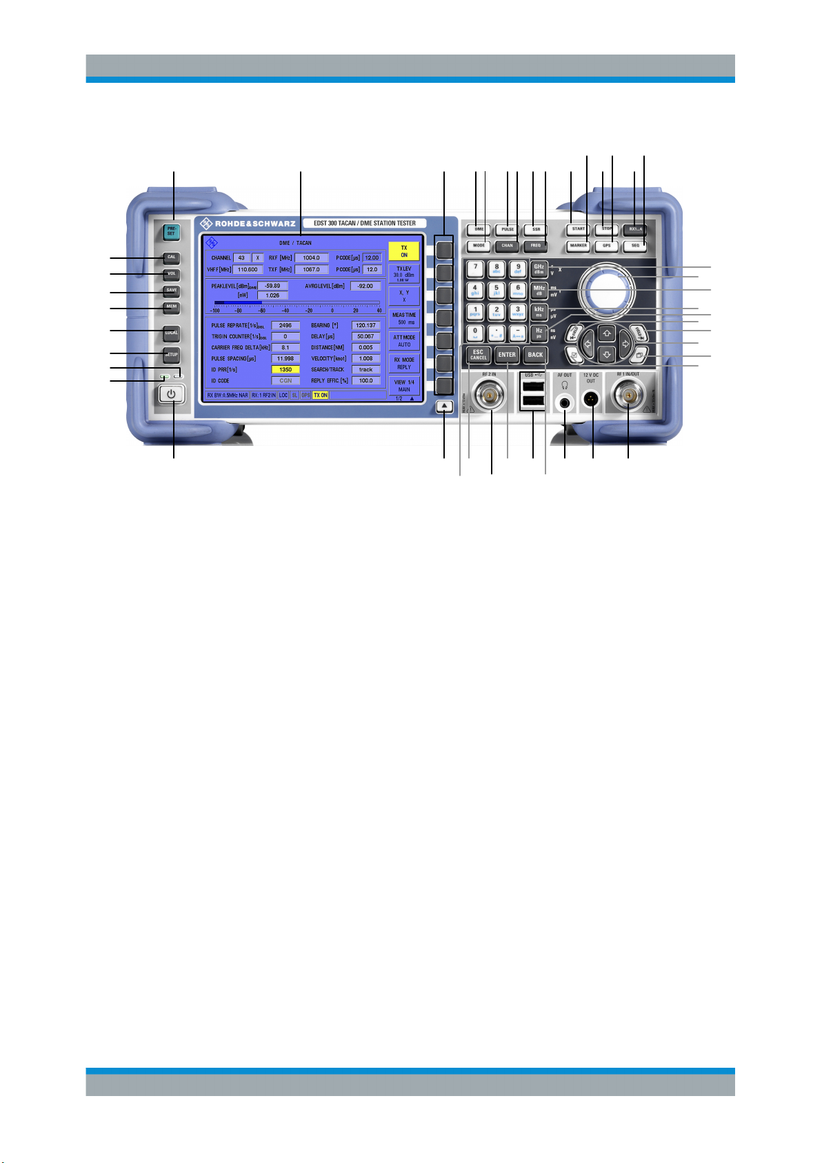
Figure 2-1: Front panel view of the R&S EDST300
1 = PRESET key
2 = TFT Colour Display ( 640 x 480 Pixels)
3 = Softkeys (Program-dependent function keys)
4 = DME key (selection of DME mode)
5 = MODE key (no function)
6 = PULSE key (selection of Pulse view mode, option)
7 = CHAN editor key (Channel input)
8 = SSR key (no function)
9 = FREQ key (Frequency input)
10 = START key (USB )
11 = MARKER key (Marker function)
12 = STOP key (USB Data-Logger)
13 = GPS key (no function)
14 = RX1 / RX2 (selection of receiving unit; RX2 not available)
15 = SEQ key (no function)
16 = GHZ key (Frequency input in GHz)
17 = MHZ key (Frequency input in MHz)
18 = Rotary knob with ENTER function
19 = KHZ key (Frequency input in kHz)
20 = HZ key (Frequency input in Hz)
21 = Not used
22 = Not used
23 = Arrow (cursor) keys
24 = Screenshot key (Stored image of a current display)
25 = Restart FPGA
26 = RF 1 IN/OUT
27 = 12 V DC OUT
28 = AF OUT
29 = BACK key (Backspace key)
30 = USB
31 = ENTER key
32 = RF 2 IN
33 = ESC/CANCEL key
34
16
17
18
19
20
21
22
23
24
25
2635 333231 302928 27
17User Manual 5202.9121.02 ─ 01

R&S®EDST300
Getting Started
Instrument Tour
34 = Numeric keypad (numerical input)
35 = Softkey extension - toggles between different pages of menu items
36 = POWER key (ON / OFF switch)
37 = Operating LED, green
38 = Standby LED, orange
39 = SETUP key (selection of SETUP menu)
40 = LOCAL key (Switch between Local / Remote)
41 = MEM key (no function)
42 = SAVE key (no function)
43 = VOL key (Volume setting)
44 = CAL key (Calibrate service function)
● Measurement Keys................................................................................................. 18
● Keypad....................................................................................................................19
● Navigation Keys (23)...............................................................................................19
● Rotary Knob (18).....................................................................................................20
● System Keys........................................................................................................... 20
● Currently Not Used Keys.........................................................................................21
● Front Panel Interfaces.............................................................................................21
2.3.1.1 Measurement Keys
Measurement keys provide access to the most common measurement settings and
functions.
A detailed description of the corresponding functions is provided in Chapter 5, "Config-
uring and Performing Measurements", on page 53.
Table 2-1: Measurement keys
Measurement key Assigned functions
DME (4)
PULSE (6)
SEQ (15)
CHAN (7)
RX1 / RX2 (14)
FREQ (9) Sets the center frequency and the start and stop frequencies for the fre-
START (10)
STOP (12)
MARKER (11) Sets and positions a measurement marker
Softkeys (3)
More softkeys (35)
Selects a specific measurement mode
Selects the input to the R&S EDST300 used for measurement (channel,
receiver antenna input)
quency range under consideration
Starts and stops a measurement
Variable, software-defined keys; functions depend on measurement
mode and current display.
The arrow toggles between different windows of functions in the same
menu.
18User Manual 5202.9121.02 ─ 01

R&S®EDST300
Getting Started
Instrument Tour
2.3.1.2 Keypad
The keys in the data entry keypad are used to enter alphanumeric data and units.
Data entry keys are only enabled while the cursor is placed on a data input field in a
dialog. Their function depends on the data type of the input field.
Keys Description
0...9/abc Enters the corresponding numbers (in numeric input fields) or characters (char-
. Inserts a decimal point (numeric input fields) or dot (character input fields) at
- Changes the sign of a numeric parameter. In the case of an alphanumeric
+/- Changes the sign of a numeric parameter. In the case of an alphanumeric
Unit keys Adds the selected unit to the entered numeric value and completes the entry.
_ Adds a blank in a character input field.
*... # Enters special characters. Toggles through the available characters if the key is
A ↔ a Toggles between uppercase and lowercase characters.
acter input fields).
the cursor position. Multiple decimal points are not allowed.
parameter, inserts a hyphen at the cursor position.
parameter, inserts a hyphen at the cursor position.
pressed several times in a row.
BACK Deletes the last character before the cursor position or the selected character
ENTER
ESC/CANCEL
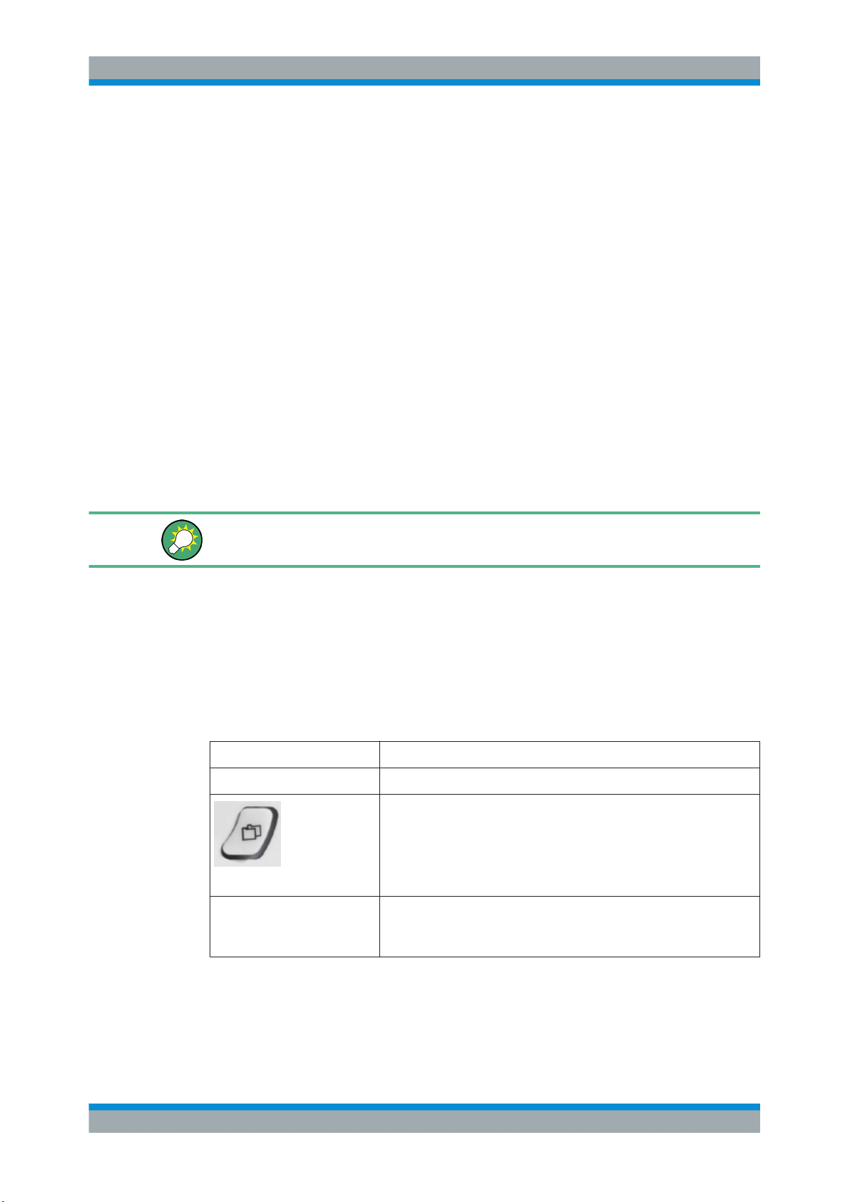
2.3.1.3 Navigation Keys (23)
The navigation keys consist of four arrow keys which are used for navigation, alternatively to the rotary knob.
Up/ Down Keys
The up and down arrow keys do the following:
sequence.
●
Concludes the entry of dimensionless entries. For other entries, this key
can be used instead of the default unit key. The new value is accepted.
●
Confirms ("OK") and closes open input windows.
●
In a dialog box, selects the default or focused button.
●
In a dialog box, activates the edit mode for the focused area, if available.
●
In a dialog box, activates or deactivates the selected option of the focused
area.
●
Calls the next menu level.
Pressing the rotary knob has the same effect.
●
Closes the open window without accepting new entries; the old value or
parameter is retained.
●
Closes all kinds of dialog boxes.
●
In dialog boxes that contain a "Cancel" button it activates that button.
●
In a numeric edit dialog box, increase or decrease the instrument parameter.
●
In a list, table, window or dialog box, scroll vertically.
19User Manual 5202.9121.02 ─ 01
R&S®EDST300
Left/ Right Keys
The left and right arrow keys do the following:
●
In an alphanumeric edit dialog box, move the cursor forward and back.
●
In a list, table, window or dialog box, scroll horizontally.
Getting Started
Instrument Tour
2.3.1.4 Rotary Knob (18)
The rotary knob has several functions:
●
Increases (clockwise direction) or decreases (counter-clockwise direction) numeric
values at a defined step width in editing mode
●
Scrolls within lists, tables or tree views
●
Acts like the ENTER key, when it is pressed.
●
Shifts the selection bar within focused areas (e.g. lists), if the edit mode is activated.
●
Moves the scroll bar vertically, if the scroll bar is focused and the edit mode is activated.
Turning or pressing the rotary knob is equivalent to pressing the UP and DOWN keys
or the ENTER key in the keypad.
2.3.1.5 System Keys
System keys set the instrument to a predefined state, change basic settings, and provide print and display functions.
A detailed description of the corresponding functions is provided in Chapter 7, "General
Instrument Setup", on page 80.
Table 2-2: SYSTEM keys
SYSTEM key Assigned functions
PRESET (1) Resets the instrument to the default state.
Creates a screenshot of the current display
Screenshot (24)
Status LEDs (37, 38) Status of operation: green if power is on
Standby LED: orange if software is shut down, but power is not switched
off
20User Manual 5202.9121.02 ─ 01
R&S®EDST300
Getting Started
Instrument Tour
SYSTEM key Assigned functions
SETUP (39)
LOCAL (40) Switches between remote and local operation of the R&S EDST300
VOL (43) Volume control for audio output
CAL (44) Starts a calibration on the R&S EDST300
2.3.1.6 Currently Not Used Keys
Some keys are currently not used, but are reserved for future use.
●
MODE (5)
●
SSR (8)
●
GPS (13)
●
RX1 / RX2 (14)
●
MEM (41)
●
SAVE (42)
Provides basic instrument configuration functions, e.g.:
●
Reference frequency (external/internal), noise source
●
Date, time, display configuration
●
LAN interface
●
Self-alignment
●
Software update and enabling of options
●
Information about instrument configuration incl. software version and
system error messages
●
Service support functions (self test etc.)
(21)
2.3.1.7 Front Panel Interfaces
(22)
Various interfaces are provided on the front panel of the R&S EDST300.
● Antenna Connections RF1 IN/OUT (26) and RF2 IN (32).......................................21
● Voltage Supply for External Consumers: 12 VDC OUT (27)...................................22
● Headphone Output AF OUT (28)............................................................................ 22
● USB Interface (29).................................................................................................. 22
Antenna Connections RF1 IN/OUT (26) and RF2 IN (32)
In the standard R&S EDST300 base unit, a single receiving antenna connection RF1
IN/OUT (26) is provided. Optionally, another connector (RF2 IN, 32) for a second
receiver unit is available (R&S EDST300-B1).
(25)
21User Manual 5202.9121.02 ─ 01
R&S®EDST300
Getting Started
Instrument Tour
RF input for the receiver units
Input level: max. +30 dBm (data stability up to 10 dBm)
Frequency range: 960 MHz ... 1215 MHz
VSWR: <1.5
Connector: N-socket, 50Ω
RF output with interrogator options
If the R&S EDST300 is equipped with the interrogator option R&S EDST300-B2, the
RF1 IN/OUT connector can also be used to provide HF output to a transmitter antenna.
The antenna has an equivalent frequency range and (peak) power range (1 W).
Possible destruction of laboratory equipment
To prevent destruction of laboratory equipment in laboratory operation, it is essential
that you insert an attenuation element between the laboratory equipment and the
R&S EDST300.
Table 2-3: Low-Power Interrogator, Option R&S
Output power: max. 1 W (+30 dBm) ±1.5 dB
Frequency range: 960 MHz ... 1215 MHz
Channel offset: 1 MHz
Distance range: 5.4 NM (approx. 10 km)
Resolution: 0.1 m
Deviation: ≤5 m
Connector: N-socket, 50 Ω
EDST300-B2
Voltage Supply for External Consumers: 12 VDC OUT (27)
The R&S EDST300 provides a power supply for connected external devices at the 3pole circular 12 VDC OUT connector. The output for external consumers such as an
active receiving antenna is supplied permanently with 12 VDC / 300 mA.
Headphone Output AF OUT (28)
Audio output is available by connecting a headphone to the 3.5 mm jack plug AF OUT.
USB Interface (29)
The front panel provides two female USB connectors (USB-A) to connect devices like
a memory stick to store and reload instrument settings and measurement data. Only
USB sticks using the FAT / FAT32 file system are supported.
22User Manual 5202.9121.02 ─ 01
R&S®EDST300
Getting Started
Instrument Tour
The connectors are standard USB 2.0 ports with a maximum transmission rate of
approximately 30 Mbit/s.
Note that there are two more USB (standard 3.0) interfaces on the rear panel of the
R&S EDST300, see Chapter 2.3.2.6, "USB (8)", on page 25.
2.3.2 Rear Panel View
This figure shows the rear panel view of the R&S EDST300. The individual elements
are described in more detail in the subsequent sections.
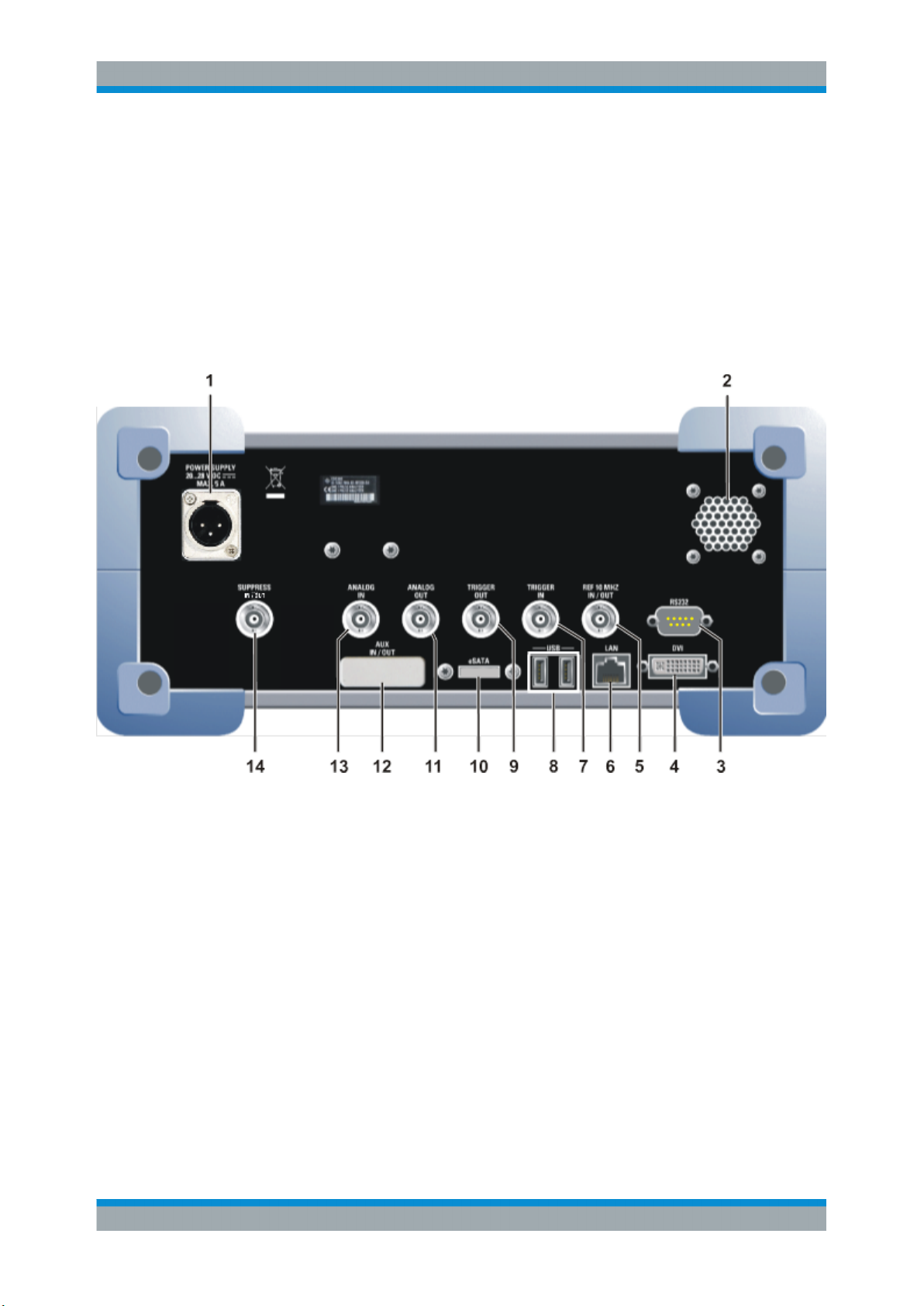
Figure 2-2: Rear panel view of the R&S EDST300
1 = POWER SUPPLY (24 VDC) power supply connection for table power pack/external feed
2 = Speaker
3 = RS232 interface
4 = DVI-D interface
5 = REF 10 MHZ IN/OUT
6 = LAN interface
7 = TRIGGER IN
8 = 2 x USB
9 = TRIGGER OUT
10 = ESATA (no function)
11 = ANALOG OUT
12 = AUX IN/OUT (no function)
13 = ANALOG IN
14 = SUPRESS IN/OUT
● DC Power Supply Connection (1)........................................................................... 24
● DVI (4).....................................................................................................................24
● REF 10 MHz IN/OUT (5).........................................................................................24
● LAN Interface (6).....................................................................................................24
23User Manual 5202.9121.02 ─ 01

R&S®EDST300
Getting Started
Instrument Tour
● TRIGGER INPUT (7) / OUTPUT (9)....................................................................... 24
● USB (8)................................................................................................................... 25
● ANALOG OUT (11) / ANALOG IN (13) Connectors................................................25
● SUPPRESS IN / OUT (14) Connector.................................................................... 25
2.3.2.1 DC Power Supply Connection (1)
Operate the R&S EDST300 on DC power only. The DC power can be supplied either
by the battery pack or power supply unit provided with the instrument, or by an appropriate external DC power source. The connector for an external DC power supply is
located on the rear panel of the instrument. An input voltage of 20 VDC to 28 VDC and
a maximum current of 5 A can be provided at this connector.
For details, refer to Chapter 2.2.2.4, "Connecting the Power Supply", on page 12.
2.3.2.2 DVI (4)
You can connect an external (TFT) monitor or other display device to the
R&S EDST300's DVI (Digital visual interface) to provide an enlarged display. The interface consists of a DVI-D socket (24+1).
For details, see Chapter 2.2.3.4, "Connecting an External Monitor", on page 16.
2.3.2.3 REF 10 MHz IN/OUT (5)
The REF 10 MHZ IN/OUT connector is used to provide an external reference signal to
the R&S EDST300, or from the R&S EDST300 to a connected device. In either case,
the reference signal is at 10 MHz, with a power level of 1 V
50 Ω socket.
. The connector is a BNC
eff
Whether the connector is used for input or output must be configured in the general
instrument settings (SETUP key, see Chapter 5.1.3, "Configuring the Reference Fre-
quency", on page 56).
2.3.2.4 LAN Interface (6)
The LAN interface can be used to connect the R&S EDST300 to a local network for
remote control, printouts or data transfer. A data transfer rate of up to 1 Gbit per second is possible. The IP address and subnet mask are configured in the general instrument settings (see Chapter 7.2, "Setting Up a Network (LAN) Connection",
on page 81).
2.3.2.5 TRIGGER INPUT (7) / OUTPUT (9)
Use the female BNC TRIGGER INPUT connector to input an external trigger. An external trigger, for example from the DME transmission system, can control the measurement on the R&S EDST300. The (digital) voltage levels can range from 3.3 V to 33 V.
The input impedance is 100 kΩ.
24User Manual 5202.9121.02 ─ 01

R&S®EDST300
Getting Started
Operating Basics
Use the female BNC TRIGGER OUTPUT connector to provide a trigger signal from the
R&S EDST300 to another connected device, such as the DME transmission system.
The trigger can be a pulse, ARB, or MRB signal, for example. The (digital) output signal is TTL compatible (0 V / 5 V). The output impedance is 50 Ω.
You can control the trigger signal in the measurement settings (see "Trigger Out Mode"
on page 55, "Trigger Source" on page 70)
2.3.2.6 USB (8)
The rear panel provides an additional female USB (USB-A) connector to connect a
memory stick or power sensor (see also "USB Interface (29)" on page 22).
The connectors are standard USB 3.0 ports with a maximum transmission rate of
40 Mbit/s.
2.3.2.7 ANALOG OUT (11) / ANALOG IN (13) Connectors
Various analog signals can be provided as output at the BNC ANALOG OUT connector. The signal is output with a peak power level of 4 V and an impedance of 50 Ω.
Which signal is to be output is configured in the general instrument settings (see Chap-
ter 5.1.2, "Configuring Signal Output", on page 55).
Analog baseband signals from another device can also be input to the R&S EDST300
for analysis via the BNC ANALOG IN connector (see Chapter 5.1.1, "Configuring the
Input Signal for Analysis", on page 53). The signal can be input with a peak power
level of 1 V and an impedance of 50 Ω.
2.3.2.8 SUPPRESS IN / OUT (14) Connector
The R&S EDST300 allows for a suppressor line signal to be input or output via the
BNC SUPPRESS IN / OUT connector (see Chapter 2.2.3.2, "Connecting a Suppressor
Line", on page 15).
The (digital) voltage levels for the input can range from 8 V to 30 V (when active).
The (digital) voltage levels for the output depend on the power supply of the
R&S EDST300. The power supply ranges from 20 V to 28 V; the output voltage is the
supplied voltage minus approx. 1 V.
In both cases, the impedance is 30 kΩ.
2.4 Operating Basics
This chapter provides an overview on how to work with the R&S EDST300. It describes
what kind of information is displayed on the screen and how to operate the
R&S EDST300 via the front panel keys and other interaction methods.
25User Manual 5202.9121.02 ─ 01
R&S®EDST300
Getting Started
Operating Basics
2.4.1 Understanding the Display Information
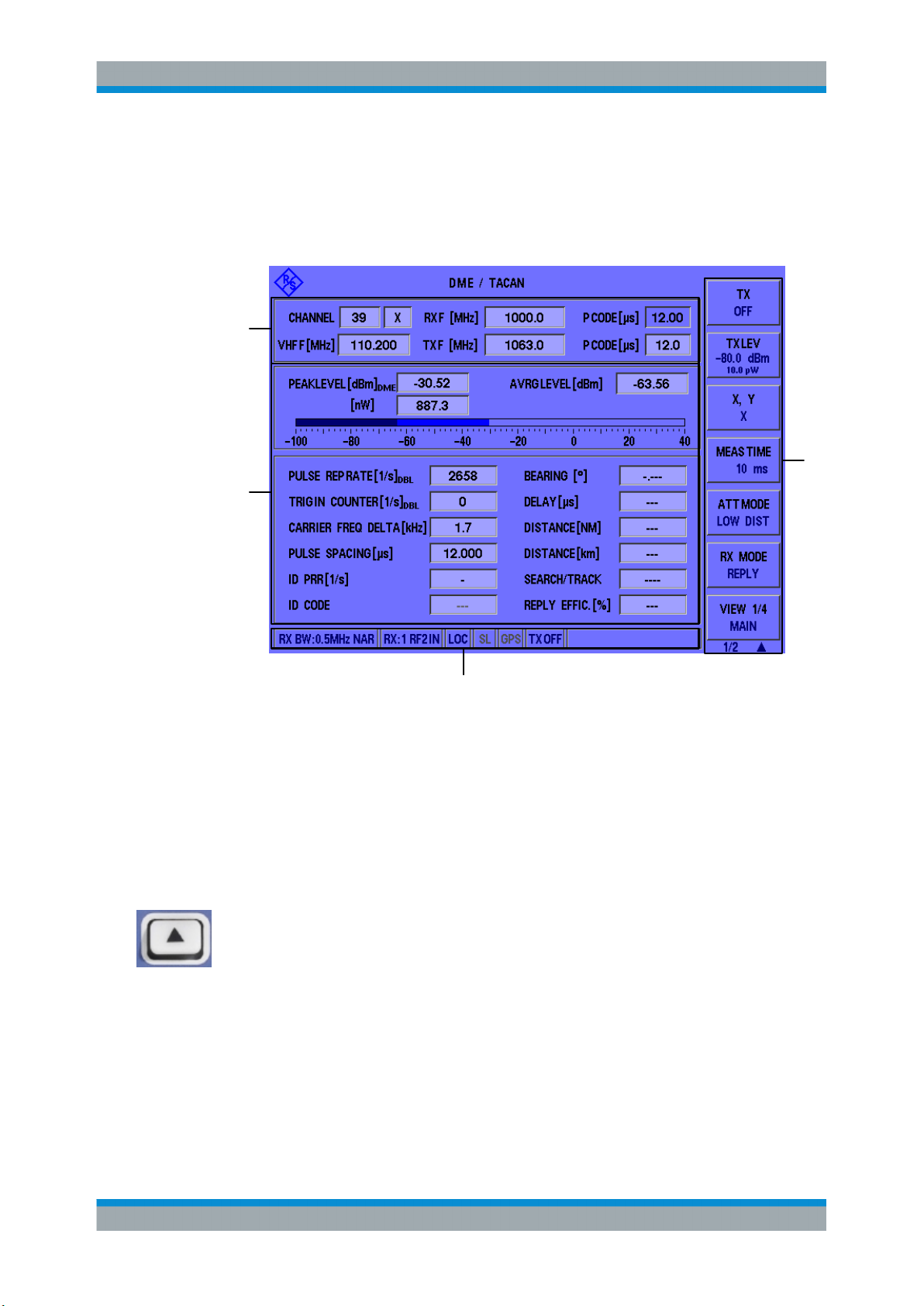
The following figure shows a typical screen display on the R&S EDST300. All different
screen elements are labeled. They are explained in more detail in the following sections.
4
3
1
2
Figure 2-3: Typical R&S EDST300 screen display (using DME mode as an example)
1 = Softkeys to edit settings and activate functions
2 = Status bar
3 = Measurement result area
4 = Measurement settings area
Softkeys
Softkeys are virtual function keys whose actual function is defined by the software,
depending on the currently selected measurement mode or key, or both.
In some cases, more functions are available than softkeys can be displayed at the
same time. In this case, a second menu of functions is available, indicated by "1/2" and
"2/2" beneath the softkeys in the display. To switch between the two menus of softkey
functions, press the "More softkeys" key beneath the softkeys on the front panel of the
R&S EDST300.
Measurement settings and results area
During a measurement, the available settings are displayed at the top of the screen;
the measurement results at the bottom. If a general instrument setting or data management function is selected, the settings and information are displayed in the main part of
the screen.
26User Manual 5202.9121.02 ─ 01
R&S®EDST300
Getting Started
Operating Basics
Which settings and results are displayed depends on the current measurement or
instrument function. See the following chapters for details:
●
Chapter 5, "Configuring and Performing Measurements", on page 53
●
Chapter 7, "General Instrument Setup", on page 80
●
Chapter 6, "Data Management", on page 74
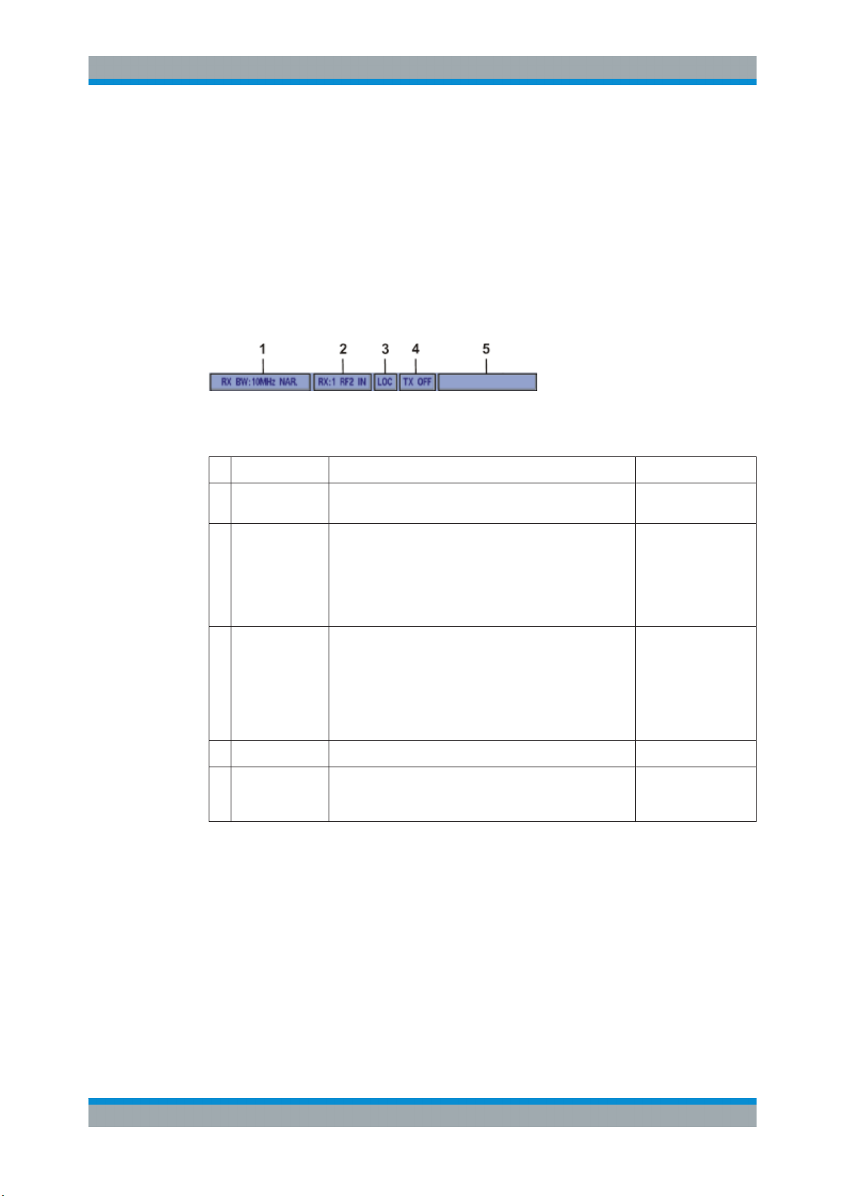
Status bar
The status bar at the bottom of the screen contains information on the operating status
of the instrument and connected devices.
Figure 2-4: R&S EDST300 status bar
Table 2-4: Information in the R&S EDST300 status bar
Section Function Example
1 Input settings Input settings, e.g. the set RF and demodulation band-
width (narrow, wide).
2 RX connectors Connector used for each receive channel (RX1 / RX2
(optional))
3 Operating mode Local or remote operation of the instrument
LOC: local operation (directly on the instrument)
REM: remote operation by external PC (can be stopped
using LOCAL key on front panel)
RLC: (REMOTELOCK) local operation is locked by remote
control
4 TX status Indicates use of RX connectors for transmission (ON/OFF)
5 Operating status Messages on the type of power supply (battery/mains) cur-
rently in use, as well as the data logging status of the
instrument, if applicable (see Error and Status Messages).
2.4.2 Accessing the Functionality
All functions available on the R&S EDST300 can be accessed using the keys on the
front panel of the instrument. Some keys provide a softkey menu on the display with
further functions and settings.
RX BW:0.5MHz NAR
RX:1 RF2 IN
(The RF input for
receive channel
"RX1" is provided by
the RF2 IN connector)
LOC
TX ON
USB LOGGING ON
To change a setting or activate a function
1. Select a key on the front panel of the instrument to activate a function directly, or to
display a softkey menu.
27User Manual 5202.9121.02 ─ 01
R&S®EDST300
Getting Started
Operating Basics
2.
Select the softkey for the setting or function as required.
If necessary, select the "More softkeys" key to switch to the second softkey menu.
The function is activated, or a new window is displayed to view or change specific
settings.
3. To set the focus on a specific setting in the displayed window, scroll through the
individual settings by turning the rotary knob or pressing the Up and Down arrow
keys on the front panel (see Chapter 2.3.1.3, "Navigation Keys (23)", on page 19).
4. To edit the currently selected setting, press the rotary knob or the ENTER key on
the front panel.
5. Scroll through the available setting values by turning the rotary knob or pressing
the Up and Down arrow keys on the front panel, or enter a numeric or alphanumeric value as described in Chapter 2.4.3, "Entering Data", on page 28.
6. Confirm the new setting by pressing the rotary knob or the ENTER key on the front
panel.
2.4.3 Entering Data
Data can be entered in input fields using elements provided by the front panel, e.g. the
keypad, rotary knob, or navigation keys.
The rotary knob has the same effect as the ENTER key when it is pressed.
Red input fields - invalid input
If you enter invalid data in an input field, the value is displayed in red and cannot be
stored.
2.4.3.1 Entering Numeric Parameters
If a field requires numeric input, the keypad provides only numbers.
1. Enter the parameter value using the keypad, or change the currently used parameter value by turning the rotary knob or pressing the Up or Down arrow keys.
2. After entering the numeric value via keypad, press the corresponding unit key.
The unit is added to the entry.
3. If the parameter does not require a unit, confirm the entered value by pressing the
ENTER key or any of the unit keys.
28User Manual 5202.9121.02 ─ 01

R&S®EDST300
Getting Started
Operating Basics
2.4.3.2 Entering Alphanumeric Parameters
If a field requires alphanumeric input, you can use the keypad on the front panel of the
R&S EDST300. Every alphanumeric key represents several characters and one number. The decimal point key (.) represents special characters, and the sign key (-) toggles between capital and small letters. For the assignment refer to Table 2-5.
Entering numbers and (special) characters via the keypad
1. Press the key once to enter the first possible value.
2. All characters available via this key are displayed.
3. To choose another value provided by this key, press the key again, until your
desired value is displayed.
4. With every key stroke the next possible value of this key is displayed. If all possible
values have been displayed, the series starts with the first value again. For information on the series refer to Table 2-5.
5. To change from capital to small letters and vice versa, press the sign key (-).
6. When you have chosen the desired value, wait for 2 seconds (to use the same key
again), or start the next entry by pressing another key.
Entering a blank
► Press the "0" key and wait 2 seconds.
Correcting an entry
1. Using the arrow keys (see Chapter 2.3.1.3, "Navigation Keys (23)", on page 19),
move the cursor to the right of the entry you want to delete.
2. Press the BACK key.
The entry to the left of the cursor is deleted.
3. Enter your correction.
Completing the entry
► Press the ENTER key or the rotary knob.
For numeric values, the default unit is appended to the numeric input.
To enter a value using a different unit, select the corresponding
Aborting the entry
► Press the ESC key.
The previous entry is restored.
29User Manual 5202.9121.02 ─ 01
R&S®EDST300
Getting Started
Operating Basics
Table 2-5: Keys for alphanumeric parameters
Key name
(upper inscription)
7 7 µ Ω ° € ¥ $ ¢
8 A B C 8 Ä ÆÅ Ç
9 D E F 9 É
4 G H I 4
5 J K L 5
6 M N O 6 Ň Ö
1 P Q R S 1
2 T U V 2 Ü
3 W X Y Z 3
0 <blank> 0 – @ + / \ < > = % &
. . * : _ , ; " ' ? ( ) #
– <toggles between capital and small letters>
2.4.4 Error and Status Messages
Series of (special) characters and number provided
If errors or irregularities are detected, a keyword or error message is displayed at the
top of the window. If an error occurs that affects the measurement, UNCAL is displayed in red letters at the top of the screen. In this case, check the error log for
missed errors. The UNCAL display is only removed when the R&S EDST300 is
switched off.
All error and status messages displayed on the R&S EDST300 are also stored to an
error log on the instrument for later inspection (see Chapter 7.3.1, "Error Log",
on page 85).
The status bar contains status messages for the used power supply or data operations.
Table 2-6: Status Messages
Message Description
Battery The internal battery pack is currently supplying power to the R&S EDST300.
Mains The AC power adapter is currently supplying power to the R&S EDST300.
Mount USB-Stick
Can't mount
USB-Stick
Mount USB-Stick:
OK
No USB storage device has been connected to the R&S EDST300 yet, for example for data logging
The USB storage device connected to the R&S EDST300 could not be read correctly.
The USB storage device connected to the R&S EDST300 is ready to store data.
30User Manual 5202.9121.02 ─ 01

R&S®EDST300
Getting Started
Operating Basics
Message Description
USB LOGGING ON
LOGGING STOPPED
Data logging to a USB storage device is active (see Chapter 6, "Data Manage-
ment", on page 74)
Data logging to a USB storage device was stopped (see Chapter 6, "Data Man-
agement", on page 74)
31User Manual 5202.9121.02 ─ 01

R&S®EDST300
3 Measurement Basics
Measurement Basics
Evaluating DME Signals
Some background knowledge on basic terms and principles used in DME/Pulse measurements is provided here for a better understanding of the required configuration settings.
● Evaluating DME Signals..........................................................................................32
● Reply Efficiency.......................................................................................................33
● RF Attenuator..........................................................................................................33
3.1 Evaluating DME Signals
DME ground stations constantly send out squitter pulses or replies to other aircrafts'
DME interrogations. Therefore it is necessary to recognize which answers belong to
the interrogator's own requests. This is usually solved in 3 possible modes (stages):
Search mode: In this mode, the interrogator sends request pulses on a specific channel to a ground station and searches the corresponding reply pulses in the output pulses of the ground station.
Initially, there is no information about the possible distance of the ground station. After
sending out an interrogation, all reply pulses for a specified duration (for example, the
next 4 ms) are collected. For a certain number of interrogations the pulses can be
expected to accumulate around one delay value, because one sender's reply pulses all
have the same delay. Other pulses are evenly spread. If the accumulation is clear
enough, the R&S EDST300 changes to "track" mode.
In this mode, the pulse repetition rate can be up to 150 pp/s (pulse pairs per second).
However, after 30 seconds the pulse repetition rate in the search mode must be
reduced to 30 pp/s.
Track mode: The delay and relative speed of the reply pulse is known. So for every
outgoing pulse the R&S EDST300 can calculate a prediction where the next reply
pulse is expected. If a reply pulse matches the prediction, a new distance value for the
ground station is generated. The reply efficiency describes the percentage of valid
replies (see Chapter 3.2, "Reply Efficiency", on page 33). As long as the reply efficiency is above 50 %, the R&S EDST300 remains in "track" mode.
Memory mode: The number of valid replies is too low to obtain reliable distance information. This may happen in difficult receiving situations or during the ID transmission.
The R&S EDST300 still sends out pulses and calculates a prediction from the last valid
replies. If the reply efficiency rises above 50 %, the R&S EDST300 immediately returns
to the "track" mode. But after a specified time (typically 10 s) the track is considered to
be lost and the R&S EDST300 returns to the "search" mode to start over.
The reply efficiency is the criterion to switch between search/track/memory mode. It is
calculated with all interrogations during a specific time (for example the last 2 s). If this
value is decreased, the R&S EDST300 moves to the "track" mode more quickly, but
also returns to the "memory" mode more quickly.
32User Manual 5202.9121.02 ─ 01

R&S®EDST300
Measurement Basics
RF Attenuator
3.2 Reply Efficiency
The reply efficiency of a DME system is the ratio of the number of sent pulses to the
number of received interrogation pulses from aircraft. A reply efficiency of 100 % is
very rarely achieved since there are several reasons why no reply pulse is sent on an
interrogation pulse request:
●
Interrogation pulse during the dead time of the receiver
●
Interrogation pulse occurs in the key down time of an ID sequence (or during an
MRB/ARB sequence of a TACAN ground station)
●
Level of the interrogation pulse below the receiver sensitivity of the ground station.
The reply efficiency drops dramatically when the maximum distance to the ground station is reached.
You must define a minimum reply efficiency that must be exceeded before the interrogator switches to track or search mode (see Chapter 3.1, "Evaluating DME Signals",
on page 32). Lower values are useful in difficult receiving conditions, for instance when
the signals are weak. However, if the value is too low, random pulses that are mistaken
for a reply can mislead the interrogator into thinking it is on a good track. Thus, you
must determine the appropriate setting for the current transmission situation.
3.3 RF Attenuator
Access: DME / PULSE > "Att.Mode Auto"
The attenuation mode determines the sensitivity of the receiver board. Depending on
the level of the incoming signal, the attenuator must avoid overload due to high-level
signals, while avoiding signal distortion for weak signals. The attenuation mode
changes the sensitivity of the receiver board by selecting a different signal path for
each mode.
Figure 3-1: Signal paths for different attenuation modes
Select the attenuator mode such that the input level always remains within the specified range.
33User Manual 5202.9121.02 ─ 01

R&S®EDST300
Measurement Basics
RF Attenuator
Risk of hardware damage due to high power levels
Do not exceed the maximum input level of +13 dBm at the RF2 Input connector, or
32 dBm at the RF1 connector!
Table 3-1: Input level ranges for different attenuation modes
Attenuation
mode
Low Noise -110 …
Norm -100 … +5 dBm -90 … +20 dBm -90 … +0 dBm
Low Distortion -85 … +12 dBm -75 … +32 dBm -75 … +12 dBm
Auto -110 …
Average input
level
-10 dBm
+12 dBm
Peak input level (RF 1) Peak input level (RF 2)
-100 … +10 dBm -100 … -10 dBm
-100 … +32 dBm -100 … +12 dBm
34User Manual 5202.9121.02 ─ 01

R&S®EDST300
4 Measurements and Results
Measurements and Results
DME and TACAN Measurement Mode
The R&S EDST300 provides different measurement modes depending on the task at
hand and the required results.
●
DME/TACAN measurement mode: determines numeric signal parameters for a
specific DME/TACAN interrogator or transponder channel. The measurement
results can be logged and output simultaneously to the measurement.
TACAN measurements require the TACAN option (R&S EDST300-K1).
●
Pulse analysis mode: measures the power levels at a specific interrogator or
transponder channel frequency to detect pulses and displays them in a power vs.
time diagram. Additional signal parameters are not determined; data logging is not
available.
Remote command:
<RX>:MEASMODE? on page 107
● DME and TACAN Measurement Mode...................................................................35
● Graphical Pulse Analysis........................................................................................ 45
4.1 DME and TACAN Measurement Mode
Access: DME
If the appropriate hardware option (Low-Power Interrogator, R&S EDST300-B2) is
installed, the R&S EDST300 can act as a DME interrogator. It sends out pulses to the
ground station which returns the signals to the R&S EDST300 at a different frequency
with a delay (see Chapter 3.1, "Evaluating DME Signals", on page 32).
The Low-Power Interrogator provides a pulse output power of 1 W for the local area
(testing DME / TACAN ground stations, range 5.4 NM).
Risk of damage of life due to RF radiation during transmission
Observe the special safety instructions for the transmitter described in Chapter 2.2.1,
"Safety Instructions for the R&S EDST300 with an Active Transmitter", on page 8.
Basic measurement process
Initially, there is no information about the possible distance of the ground station. Thus,
the R&S EDST300 interrogator starts in search mode. It sends request pulses on a
specific channel to a ground station. Then it searches the corresponding reply pulses
in the output pulses of the ground station.
Once a certain number of reply pulses accumulate around one delay value, the
R&S EDST300 changes to track mode and reduces the reply pulse rate. While in the
track mode, the R&S EDST300 displays the slant range to the ground station (indica-
35User Manual 5202.9121.02 ─ 01

R&S®EDST300
Measurements and Results
DME and TACAN Measurement Mode
ted in nautical miles and meters). If the R&S EDST300 loses the synchronization, it
moves to the memory mode and attempts to restore the synchronization based on the
defined request rate. If this is successful, the R&S EDST300 returns to the track mode.
Otherwise it returns to the search mode, increasing the number of request pulses to
restore the synchronization.
Receiver modes
The R&S EDST300 can measure either the pulses sent by the interrogator to the
ground station, or the reply pulses sent from the ground station to the interrogator. You
must specify in the measurement settings which signals you want to measure and analyze.
Remote command:
<RX>:MEASMODE_DME on page 107
● Displayed Measurement Settings........................................................................... 36
● DME Measurement Results.................................................................................... 36
● TACAN Measurement Results................................................................................40
● ID Measurement Results.........................................................................................44
4.1.1 Displayed Measurement Settings
For all DME/Pulse measurements, the following common settings are displayed (for
details see Chapter 5.2, "Configuring DME Measurements", on page 60):
Table 4-1: Distance measurement settings
Display Description
CHANNEL Receiver frequency channel according to the ICAO frequency list;
RX F [MHz] Receiver frequency for the reply pulses of the ground station
P.CODE [µs] Reply pulse code (distance of the double pulses), according to the ICAO fre-
quency list
VHFF Frequency of the interrogator pulse transmitted to the ground station by the
R&S EDST300
TX.F [MHz] Transmit frequency for the interrogator pulse transmitted to the ground station by
the R&S EDST300
P.CODE [µs] Interrogator pulse code (distance of the double pulses), according to the ICAO
frequency list.
4.1.2 DME Measurement Results
Access: DME
36User Manual 5202.9121.02 ─ 01

R&S®EDST300
Measurements and Results
DME and TACAN Measurement Mode
Distance measurements are performed in a specific mode on the R&S EDST300, the
"DME" mode.
The following results are displayed for a distance measurement.
Graphical results are described in Chapter 5.3, "Performing Pulse Analysis",
on page 65.
Background information on distance measurement equipment (DME) is provided in
Chapter 3.1, "Evaluating DME Signals", on page 32.
PEAKLEVEL [dBm] / [W]...............................................................................................38
AVRG.LEVEL [dBm]..................................................................................................... 38
Bargraph....................................................................................................................... 38
PULSE REPETITION RATE [1/s]................................................................................. 38
TRIG. IN COUNTER [1/s]............................................................................................. 38
CARRIER FREQ DELTA [kHz]..................................................................................... 38
PULSE SPACING [µs].................................................................................................. 38
ID PRR [1/s].................................................................................................................. 39
ID-CODE.......................................................................................................................39
BEARING [°]..................................................................................................................39
DELAY [µs]....................................................................................................................39
DISTANCE [km]............................................................................................................ 39
DISTANCE [NM]........................................................................................................... 39
SEARCH/TRACK..........................................................................................................39
REPLY EFFIC. [%]........................................................................................................40
37User Manual 5202.9121.02 ─ 01

R&S®EDST300
Measurements and Results
DME and TACAN Measurement Mode
PEAKLEVEL [dBm] / [W]
Peak measured level of the received signal
Note: A small "DME" indicates that the level refers to valid DME pulses (only double
pulses with the correct pulse spacing). The signal can also contain components with
higher levels which are not DME (like jammers).
If no "DME" is displayed, the maximum level in the signal is provided.
If external attenuation is applied (see "External Attenuation" on page 54), the attenu-
ation considered for the peak level is indicated.
Remote command:
<RX>:DME:PEAKLEVEL? on page 125
AVRG.LEVEL [dBm]
Average measured level of the received signal
Remote command:
<RX>:DME:AVRGLEVEL? on page 125
Bargraph
Graphical display of the measured received signal level.
The dark blue bar indicates the average level; the light blue bar indicates the peak
level.
PULSE REPETITION RATE [1/s]
Measured pulse repetition rate of the DME signal, i.e. number of interrogator/reply pulses (pairs) per second; only updated once per second
"DBL" indicates that double bursts are counted, "SGL" indicates that single pulses are
counted (see Count Pulses)
Remote command:
<RX>:DME:PULSE_REPT_RATE? on page 126
TRIG. IN COUNTER [1/s]
Number of measured trigger events on external trigger input
"DBL" indicates that double bursts are counted, "SGL" indicates that single pulses are
counted (see Count Pulses)
CARRIER FREQ DELTA [kHz]
Measured frequency deviation relative to the defined channel frequency
Remote command:
<RX>:DME:CARRIER_F_DELTA? on page 125
PULSE SPACING [µs]
Measured pulse spacing between the pulses of a pulse pair
38User Manual 5202.9121.02 ─ 01

R&S®EDST300
Measurements and Results
DME and TACAN Measurement Mode
Remote command:
<RX>:DME:PULSE_SPACING? on page 126
ID PRR [1/s]
Pulse repetition rate during ID transmissions. When an ID is detected, this field blinks
yellow and indicates the measured frequency.
Remote command:
<RX>:DME:ID_PRR? on page 125
ID-CODE
Morse-decoded ID with three or four letters. Since the ID is usually only transmitted
every 40 seconds, the ID remains on screen for 60 seconds.
Remote command:
<RX>:DME:ID_CODE? on page 125
BEARING [°]
TACAN signals only (requires option R&S EDST300-K1):
Direction of the ground station in relation to the R&S EDST300.
Remote command:
<RX>:TACAN:BEARING? on page 128
DELAY [µs]
Reply delay time, that is: the delay time between the interrogator and reply pulse,
including the ground station delay (50 µs in x mode / 56 µs in y mode)
Remote command:
<RX>:DST:DELAY? on page 127
DISTANCE [km]
Measured distance in kilometers, calculated from the DELAY [µs]
Remote command:
<RX>:DST:DST? on page 127
DISTANCE [NM]
Measured distance in nautical miles, calculated from the DELAY [µs]
Remote command:
<RX>:DST:DST? on page 127
SEARCH/TRACK
Current mode of the interrogator (see Chapter 3.1, "Evaluating DME Signals",
on page 32)
"Search30" indicates that the search mode has lasted longer than 30 seconds and thus
the PPR has been reduced to 30 pulses per second.
Remote command:
<RX>:DST:SOT? on page 124
39User Manual 5202.9121.02 ─ 01

R&S®EDST300
Measurements and Results
DME and TACAN Measurement Mode
REPLY EFFIC. [%]
Reply efficiency, ratio of the valid reply pulses relative to the transmitted interrogator
pulses in percent
Remote command:
<RX>:DST:REPEFF? on page 124
4.1.3 TACAN Measurement Results
Access: DME > "View" (> "TACAN1 ")
The DME part of the measurement is identical to Chapter 3.1, "Evaluating DME Sig-
nals", on page 32. However, additional parameters are displayed, including:
●
The bearing
●
The modulation depth of the AF signals
●
The frequency of the AF signals
●
The phase shift between the two AF tones
●
The absolute phase of the 15 Hz signal to the main reference burst (MRB)
●
The absolute phase of the 135 Hz signal to the auxiliary reference burst (ARB)
The R&S EDST300 can evaluate TACAN signals only if the TACAN stick with the
TACAN software is inserted in one of the USB ports (see Chapter 2.2.2.6, "Activating
the TACAN Option", on page 13).
If the TACAN stick is inserted, the DME view automatically includes the TACAN-specific results and functions. In addition to the DME results described in Chap-
ter 4.1.2, "DME Measurement Results", on page 36, the following additional results
are provided for TACAN signals.
The extended DME/TACAN view consists of several individual pages. To scroll through
the results, select the "View" softkey in the DME menu until the required page is displayed.
The main view is identical to the DME view described in Chapter 4.1.2, "DME Mea-
surement Results", on page 36.
The displayed measurement settings are described in Chapter 4.1.1, "Displayed Mea-
surement Settings", on page 36.
40User Manual 5202.9121.02 ─ 01

R&S®EDST300
Measurements and Results
DME and TACAN Measurement Mode
Figure 4-1: TACAN measurement results (page 1)
Figure 4-2: TACAN measurement results (part 2)
41User Manual 5202.9121.02 ─ 01

R&S®EDST300
Measurements and Results
DME and TACAN Measurement Mode
MOD.DEPTH 15Hz [%].................................................................................................42
MOD.DEPTH 135Hz [%]...............................................................................................42
BEARING [°]..................................................................................................................42
PHASE SHIFT [°].......................................................................................................... 42
FREQ 15Hz [Hz]........................................................................................................... 42
FREQ 135Hz [Hz]......................................................................................................... 42
PHASE 15Hz [°]............................................................................................................ 43
PHASE 135Hz [°/9]....................................................................................................... 43
Squitter+Rep [1/s]......................................................................................................... 43
MRB PRR [1/s]..............................................................................................................43
MRB PULSE COUNT....................................................................................................43
MRB PULSE SPACE [µs]............................................................................................. 43
MRB PEAK SPACE [µs]................................................................................................43
ARB PRR [1/s].............................................................................................................. 43
ARB PULSE COUNT.................................................................................................... 43
ARB PULSE SPACE [µs]..............................................................................................43
ARB PEAK SPACE [µs]................................................................................................ 44
MOD.DEPTH 15Hz [%]
Measured modulation depth of the 15 Hz signal
Remote command:
<RX>:TACAN:MOD_DEPTH_15HZ? on page 128
MOD.DEPTH 135Hz [%]
Measured modulation depth of the 135 Hz signal
Remote command:
<RX>:TACAN:MOD_DEPTH_135HZ? on page 128
BEARING [°]
TACAN signals only (requires option R&S EDST300-K1):
Direction of the ground station in relation to the R&S EDST300.
Remote command:
<RX>:TACAN:BEARING? on page 128
PHASE SHIFT [°]
Measured phase shift between the 15 Hz and 135 Hz components
Remote command:
<RX>:TACAN:PHASE_SHIFT? on page 129
FREQ 15Hz [Hz]
Measured frequency of nominal 15 Hz components
Remote command:
<RX>:TACAN:FREQ_15HZ? on page 128
FREQ 135Hz [Hz]
Measured frequency of nominal 135 Hz components
42User Manual 5202.9121.02 ─ 01

R&S®EDST300
Measurements and Results
DME and TACAN Measurement Mode
Remote command:
<RX>:TACAN:FREQ_135HZ? on page 128
PHASE 15Hz [°]
Measured phase of the 15 Hz components compared to the MRB; this value is updated
15 times per second
Remote command:
<RX>:TACAN:PHASE_15HZ? on page 129
PHASE 135Hz [°/9]
Measured phase (0° to 40°) of the 135 Hz components compared to the ARB; this
value is updated 135 times per second
Remote command:
<RX>:TACAN:PHASE_135HZ? on page 129
Squitter+Rep [1/s]
Number of measured pulses, including the replies from the ground station to the interrogator's pulses
"DBL" indicates that double bursts are counted, "SGL" indicates that single pulses are
counted (see Count Pulses)
MRB PRR [1/s]
Measured pulse repetition rate of the MRB (Main Reference Burst)
"DBL" indicates that double bursts are counted, "SGL" indicates that single pulses are
counted (see Count Pulses)
MRB PULSE COUNT
Number of pulses measured in one MRB.
"DBL" indicates that double bursts are counted, "SGL" indicates that single pulses are
counted (see Count Pulses)
MRB PULSE SPACE [µs]
Measured pulse spacing between two pulses of the MRB
MRB PEAK SPACE [µs]
Maximum measured pulse spacing between two pulses of the MRB
ARB PRR [1/s]
Measured pulse repetition rate of the ARB (Auxiliary Reference Burst)
ARB PULSE COUNT
Number of pulses measured in one ARB
"DBL" indicates that double bursts are counted, "SGL" indicates that single pulses are
counted (see Count Pulses)
ARB PULSE SPACE [µs]
Measured pulse spacing between two pulses of the ARB
43User Manual 5202.9121.02 ─ 01

R&S®EDST300
Measurements and Results
DME and TACAN Measurement Mode
ARB PEAK SPACE [µs]
Maximum measured pulse spacing between two pulses of the ARB.
4.1.4 ID Measurement Results
Access: DME > "View" > "View " > "View "
In addition to the measurement results for the reply and interrogator pulses, the measured ID pulses can also be analyzed.
The DME/TACAN view consists of several individual pages. The ID Analysis view is
the last in the series of result pages. To scroll through the results, select the "View"
softkey in the DME menu until the required page is displayed.
The following results are displayed for measured ID pulses.
The displayed measurement settings are described in Chapter 4.1.1, "Displayed Mea-
surement Settings", on page 36.
Figure 4-3: ID Analysis view
Last ID [s]......................................................................................................................45
ID Period [s].................................................................................................................. 45
EQ Pulse time [μ].......................................................................................................... 45
ID PRR [1/s].................................................................................................................. 45
Detected ID information................................................................................................ 45
44User Manual 5202.9121.02 ─ 01

R&S®EDST300
Measurements and Results
Graphical Pulse Analysis
└ ID CODE.........................................................................................................45
└ Dash Length [ms]............................................................................................45
└ Dot Length [ms]...............................................................................................45
└ Dot-Dash Gap [ms]......................................................................................... 45
└ Letter Gap [ms]............................................................................................... 45
Last ID [s]
Time since last ID pulse was measured
ID Period [s]
Time between two measured ID pulses
EQ Pulse time [μ]
Delay time of equalizer pulses from the id pulses during ID transmission
ID PRR [1/s]
Pulse repetition rate during ID transmissions. When an ID is detected, this field blinks
yellow and indicates the measured frequency.
Remote command:
<RX>:DME:ID_PRR? on page 125
Detected ID information
The following information is provided when an ID signal is detected. After 5 seconds,
the information fades to gray. After 60 seconds, the information disappears.
ID CODE ← Detected ID information
Morse-decoded ID with three or four letters. Since the ID is usually only transmitted
every 40 seconds, the ID remains on screen for several seconds.
Remote command:
<RX>:DME:ID_CODE? on page 125
Dash Length [ms] ← Detected ID information
Length of time a dash is transmitted in the used Morse code
Dot Length [ms] ← Detected ID information
Length of time a dot is transmitted in the used Morse code
Dot-Dash Gap [ms] ← Detected ID information
Length of time that passes between a transmitted dot and a dash in the used Morse
code
Letter Gap [ms] ← Detected ID information
Length of time that passes between two transmitted letters in the used Morse code
4.2 Graphical Pulse Analysis
Access: PULSE
45User Manual 5202.9121.02 ─ 01

R&S®EDST300
Measurements and Results
Graphical Pulse Analysis
R&S EDST300 pulse analysis is used to test the RF output signal of DME / TACAN
ground stations and interrogators and analyze pulse characteristics graphically. In
Pulse mode, the power levels at a specific interrogator or transponder channel frequency are measured. If user-defined criteria are fulfilled, a pulse is detected and displayed in a power vs time diagram, similarly to an oscilloscope. Additionally, characteristic pulse parameters are determined using markers in the diagram.
1
2
3
Figure 4-4: Default Pulse analysis view
1 = Selected receiver channel and frequency for measurement
2 = Marker and analysis results
3 = Power vs time diagram for measured channel
The channel and frequency to be measured can be changed directly in the Pulse view,
see "Changing the receiver (RX) channel number" on page 61 and "Changing the
receiver (RX) frequency" on page 62.
The pulse code according to the ICAO frequency list is indicated for reference (see
also Chapter B, "DME Channel Frequency List", on page 135).
For a description of the calculated marker results, see Chapter 4.2.1, "Automatic
Analysis", on page 47.
Pulse mode is meant for graphical analysis; data streaming and data logging is not
available. However, the pulse trace data can be queried remotely. For numeric results,
perform a DME/TACAN measurement (see Chapter 4.1, "DME and TACAN Measure-
ment Mode", on page 35).
46User Manual 5202.9121.02 ─ 01

R&S®EDST300
Measurements and Results
Graphical Pulse Analysis
Remote command:
<RX>:MEASMODE_PULSE on page 108
Results:
<RX>:PULSEVIEW:DATASET? on page 130
4.2.1 Automatic Analysis
By default, a set of common pulse characteristics are determined automatically.
For full analysis, the following parameters are determined:
Figure 4-5: Full analysis results in Pulse view
Pulse rise time
...............................................................................................................47
Pulse duration............................................................................................................... 48
Pulse decay time...........................................................................................................49
Pulse spacing................................................................................................................49
Pulse peak variation......................................................................................................50
Pulse rise time
Pulse rise time for each pulse in µs, calculated as the difference between two markers
(M2-M1). Marker 1 is set at 10 % of the rising pulse slope, marker 2 is set at 90 % of
the rising pulse slope.
47User Manual 5202.9121.02 ─ 01

R&S®EDST300
Measurements and Results
Graphical Pulse Analysis
Pulse duration
Pulse duration for each pulse in µs, calculated as the difference between two markers
(M2-M1). Marker 1 is set at 50 % of the rising pulse slope, marker 2 is set at 50 % of
the falling pulse slope.
48User Manual 5202.9121.02 ─ 01

R&S®EDST300
Measurements and Results
Graphical Pulse Analysis
Pulse decay time
Pulse decay time for each pulse in µs, calculated as the difference between two markers (M2-M1). Marker 1 is set at 90 % of the falling pulse slope, marker 2 is set at 10 %
of the rising pulse slope.
Pulse spacing
Pulse spacing between the pulses of a pulse pair in µs, calculated as the difference
between two markers (M2-M1). Marker 1 is set at 50 % of the rising slope of the first
pulse, marker 2 is set at 50 % of the rising slope of the second pulse.
49User Manual 5202.9121.02 ─ 01

R&S®EDST300
Measurements and Results
Graphical Pulse Analysis
Pulse peak variation
Variation in pulse peak power values in dB, calculated as the difference between two
markers (M2-M1). Marker 1 is set to the peak power level of the first pulse, marker 2 is
set to the peak power level of the second pulse.
50User Manual 5202.9121.02 ─ 01

R&S®EDST300
Measurements and Results
Graphical Pulse Analysis
4.2.2 Individual Marker Results
To determine the pulse parameters mentioned above, the markers must be set to different points in the pulse traces. Thus, displaying the markers in the diagram would not
be useful for full analysis. In this case, only the analysis results are displayed in the
pulse view (see Figure 4-5).
However, alternatively to full analysis, individual parameters can also be selected. In
this case, the markers can be displayed graphically in the diagram and the position and
values of the markers are indicated numerically in the pulse results area. Which analysis function is currently selected is also displayed in the results area and on the "Analysis" softkey.
Figure 4-6: Individual marker results and marker display in pulse analysis
For individual parameter analysis, the following information is displayed for the markers:
M2-M1...........................................................................................................................51
Mmax............................................................................................................................ 51
Mark1............................................................................................................................ 52
Mark2............................................................................................................................ 52
M2-M1
Difference between the time and power values for marker 2 and marker 1.
Mmax
Maximum measured power level in the selected pulse (see "Pulse selection for peak
marker ( Mrk. Max to Peak 1/2 )" on page 73), the time it was measured and percent-
age of total measured power at time of maximum
51User Manual 5202.9121.02 ─ 01

R&S®EDST300
Measurements and Results
Graphical Pulse Analysis
Mark1
Measured power level in pulse 1, the time it was measured and percentage of total
measured power
Mark2
Measured power level in pulse 2, the time it was measured and percentage of total
measured power
52User Manual 5202.9121.02 ─ 01

R&S®EDST300
5 Configuring and Performing Measurements
Configuring and Performing Measurements
Configuring Signal Input and Output
● Configuring Signal Input and Output.......................................................................53
● Configuring DME Measurements............................................................................60
● Performing Pulse Analysis...................................................................................... 65
5.1 Configuring Signal Input and Output
Access: SETUP
The R&S EDST300 can analyze signals received by its RF IN interface, but also provide output to the same interface. Furthermore, a reference signal can be provided as
input to the R&S EDST300 to improve accuracy of the measurements. All settings concerning signal input and output are described here.
Signal input and output settings are maintained even when you switch measurement
modes.
● Configuring the Input Signal for Analysis................................................................ 53
● Configuring Signal Output.......................................................................................55
● Configuring the Reference Frequency.................................................................... 56
● Configuring DME Interrogator Signals.................................................................... 58
5.1.1 Configuring the Input Signal for Analysis
Access: SETUP > "Signal In"
The signal to be analyzed by the R&S EDST300 can be obtained from different input
connectors.
53User Manual 5202.9121.02 ─ 01

R&S®EDST300
Configuring and Performing Measurements
Configuring Signal Input and Output
Input for RX Board 1..................................................................................................... 54
Input from (optional) RX Board 2.................................................................................. 54
External Attenuation......................................................................................................54
Fixed External Attenuation for RF input 1/2.................................................................. 55
Input for RX Board 1
Defines the input signal for the first receiver board, that is, which connector the input
signal will be taken from.
"RF 1 IN"
"RF 2 IN"
"BB IN"
Remote command:
<RX>:SETUP:INPUT on page 104
Input from (optional) RX Board 2
Not available.
External Attenuation
Activates or deactivates external attenuation.
"None"
RF input from the "RF 1 IN" connector on the front panel of the
R&S EDST300
RF input from the "RF 2 IN" connector on the front panel of the
R&S EDST300
Analog input from the ANALOG IN connector on the rear panel of the
R&S EDST300
No external attenuation is applied.
54User Manual 5202.9121.02 ─ 01

R&S®EDST300
Configuring and Performing Measurements
Configuring Signal Input and Output
"Fixed"
A fixed attenuation is applied to the RF input from the receiver board
(see "Fixed External Attenuation for RF input 1/2" on page 55). A
different attenuation level can be defined for each RF input connector.
Fixed External Attenuation for RF input 1/2
Defines the fixed power level by which the signal at the RF input 1 or 2 is attenuated
during the measurement (for External Attenuation = "Fixed").
5.1.2 Configuring Signal Output
Access: SETUP > "Signal Out"
Different signals can be provided at one of the R&S EDST300's output connectors.
Trigger Out Mode..........................................................................................................55
Analog Out.................................................................................................................... 56
Trigger Out Mode
Defines the type of trigger signal to be provided at the TRIGGER OUTPUT connector
on the rear panel of the R&S EDST300.
"PULSE_TRIGGER"
For each measured DME pulse, a square pulse with the same pulse
width is output synchronously.
"PULSE DECODED "
For each measured DME pulse pair with the correct pulse code
(=pulse spacing), a square pulse with a 1 μs pulse width is output.
55User Manual 5202.9121.02 ─ 01

R&S®EDST300
Configuring and Performing Measurements
Configuring Signal Input and Output
"INTERROG TRIGGER"
For each transmitted interrogator pulse pair, a square pulse with a
1 μs pulse width is output.
"ID_CODE"
A high signal is output during the ID transmission.
"MRB_TRGGER"
For each decoded MRB (main reference burst), a square pulse with a
1 μs pulse width is output.
Only available for TACAN analysis
"ARB_TRIGGER"
For each decoded ARB (auxiliary reference burst), a square pulse
with a 1 μs pulse width is output.
Only available for TACAN analysis (requires option R&S EDST300K1)
Remote command:
SETUP:TRIGGER_OUT_MODE on page 106
Analog Out
Defines the type of analog signal to be provided at the ANALOG OUTPUT connector
on the rear panel of the R&S EDST300.
"RX_DEMOD"
The demodulated baseband signal is output.
"DET ENVELOPE"
The peak detector envelope of the pulse signal is output.
"DET 15HZ"
The 15 Hz component in the peak detector envelope of the pulse signal is output.
Only available for TACAN analysis
"DET 135HZ"
The 135 Hz component in the peak detector envelope of the pulse
signal is output.
Only available for TACAN analysis
"DET ID"
The audio signal (detector envelope) of the ID is output (at 1350 Hz,
audible Morse code)
Remote command:
SETUP:ANALOG_OUT_MODE on page 104
5.1.3 Configuring the Reference Frequency
Access: SETUP > "Reference"
The R&S EDST300 can use the internal reference source or an external reference
source as the frequency standard for all internal oscillators. A 10 MHz crystal oscillator
is used as the internal reference source. If the external reference is used, all internal
oscillators of the R&S EDST300 are synchronized to the external reference frequency.
A reference frequency can also be provided by the R&S EDST300 to other devices
that are connected to this instrument in order to synchronize multiple devices in a measurement setup.
56User Manual 5202.9121.02 ─ 01

R&S®EDST300
Configuring and Performing Measurements
Configuring Signal Input and Output
Source...........................................................................................................................57
Ext. Reference.............................................................................................................. 57
Source
Defines whether the REF 10 MHZ IN/OUT connector on the rear panel of the
R&S EDST300 is used to receive a reference frequency from an external device, or to
provide the internal reference frequency of the R&S EDST300 as output to a connected device.
"Intern"
"Extern"
Remote command:
SETUP:REFERENCE:SOURCE on page 105
Ext. Reference
Indicates the usage and state of a reference frequency at the REF 10 MHZ IN/OUT
connector.
"Present"
The internal reference frequency of the R&S EDST300 is provided as
output to a device at the REF 10 MHZ IN/OUT connector.
The R&S EDST300 uses the external reference frequency provided
by another device at the REF 10 MHZ IN/OUT connector.
The Ext. Reference field shows the availability of a reference signal at
the connector.
A 10 MHz reference signal is provided by an external device at the
REF 10 MHZ IN/OUT connector of the R&S EDST300.
"Not present"
No reference signal is available at the REF 10 MHZ IN/OUT connector of the R&S EDST300. The internal 10 MHz reference signal is
used for measurement with the R&S EDST300.
57User Manual 5202.9121.02 ─ 01

R&S®EDST300
Configuring and Performing Measurements
Configuring Signal Input and Output
"Output"
The internal 10 MHz reference signal of the R&S EDST300 is provided as output to a device at the REF 10 MHZ IN/OUT connector
(Source = "Intern".
Remote command:
SETUP:REFERENCE:EXTREFERENCE? on page 105
5.1.4 Configuring DME Interrogator Signals
Access: SETUP > "DME Interrog"
The R&S EDST300 can act as a DME interrogator, sending out pulses to the ground
station which returns the signals to the R&S EDST300 at a different frequency with a
delay (see Chapter 3.1, "Evaluating DME Signals", on page 32).
Type of Prediction......................................................................................................... 58
Track Pulses................................................................................................................. 59
Search Pulses...............................................................................................................59
Memory Time (Tracking)...............................................................................................59
Min. Reply Effic. (Tracking)...........................................................................................59
Delay Offset.................................................................................................................. 59
TX Pulse Shape............................................................................................................ 59
ICAO Override...............................................................................................................60
Type of Prediction
Defines the type of algorithm used to calculate the expected reply pulse.
58User Manual 5202.9121.02 ─ 01

R&S®EDST300
Configuring and Performing Measurements
Configuring Signal Input and Output
During the search on a DME ground station, the time of arrival for the reply pulse is
calculated from the relative speed between the DME ground station and the interrogator.
"Linear"
"Static"
Track Pulses
Number of pulses during track mode for which the reply efficiency is calculated.
The larger the value, the more stable and accurate the results, but the slower the inter-
rogator.
Remote command:
<RX>:DST:TPULSES on page 113
Search Pulses
Number of pulses during search mode for which the reply efficiency is calculated.
The larger the value, the more stable and accurate the results, but the slower the inter-
rogator.
Remote command:
<RX>:DST:SPULSES on page 113
The time delay for the subsequent pulse is derived linearly from the
previously measured delay.
The relative speed is assumed to be zero; the time delay for the subsequent pulse is thus calculated from the mean value of previous
time delays. This setting is meant for fixed monitoring stations.
Memory Time (Tracking)
Defines the maximum time the interrogator remains in memory mode. After this time,
the next search mode is triggered. The defined time should be at least long enough to
finalize ID transmission.
Valid values are between 0.1 seconds and 50 seconds.
Min. Reply Effic. (Tracking)
Minimum reply efficiency (in percent) after which the interrogator switches between
tracking, memory and search modes (see Chapter 3.1, "Evaluating DME Signals",
on page 32).
Smaller values are better for difficult receiving conditions.
Valid values are between 20 % and 99 %.
Delay Offset
Defines an offset to the delay between the transmission of the request pulse and the
reply pulse.
This is useful to compensate for delay times caused by cable lengths, for example.
Valid values are between -100 μs and +100 μs.
TX Pulse Shape
Defines the shape of the transmitted (TX) interrogator pulse, if enabled.
●
"DME": Gauss pulse with a rise and fall time of 2.5 μs
●
"TAC": Asymmetric Gauss pulse with a rise time of 2.0 μs and a fall time of 2.7 μs
59User Manual 5202.9121.02 ─ 01

R&S®EDST300
Configuring and Performing Measurements
Configuring DME Measurements
(only available for TACAN measurements, requires option R&S EDST300-K1)
DME TAC
ICAO Override
Ignores the ICAO specifications regarding the maximum pulse repetition rate.
If the ICAO override is enabled, pulse rates of up to 6000 pulses per second are avail-
able. This is the default behavior of the R&S EDST300.
If this function is disabled, a maximum of 150 pulses per second are allowed for the
first 30 seconds, then only 30 pulses per second are allowed. This is the restriction as
required by the ICAO.
Remote command:
SETEXPERT on page 115
5.2 Configuring DME Measurements
Access: DME
DME measurements for DME and (optionally) TACAN signals are configured in the
"DME/TACAN" view.
See also Chapter 5.1.4, "Configuring DME Interrogator Signals", on page 58.
60User Manual 5202.9121.02 ─ 01

R&S®EDST300
Configuring and Performing Measurements
Configuring DME Measurements
Changing the receiver (RX) channel number................................................................61
Channel selection X, Y..................................................................................................62
Changing the receiver (RX) frequency..........................................................................62
RX Pulse Code ( P.Code )............................................................................................ 62
VHF Frequency ( VHFF ).............................................................................................. 62
Interrogator Transmission (TX) frequency.................................................................... 63
TX Pulse Code ( P.Code ).............................................................................................63
Transmitter ( TX ) State.................................................................................................63
Interrogator Transmission (TX) Level............................................................................63
Measurement Time....................................................................................................... 64
Att.Mode........................................................................................................................64
Receiver (RX) Mode......................................................................................................64
View.............................................................................................................................. 65
Interrogator Transmission (TX) Pulse Width................................................................. 65
PRR for Search Mode...................................................................................................65
PRR for Track Mode..................................................................................................... 65
Changing the receiver (RX) channel number
Access: CHAN
A DME channel is uniquely identified by its channel number (+extension) or its receive
frequency. Thus, if you set the receiver (RX) channel to a different (valid) value and
apply the change, the associated parameters are automatically adapted according to
the ICAO frequency list. The associated parameters are the channel frequency, transmit (TX) frequency, and pulse spacing.
To change the extension, use the Channel selection X, Y function.
The valid channel number range for DME channels is from 1 to 126 (see Chapter B,
"DME Channel Frequency List", on page 135).
61User Manual 5202.9121.02 ─ 01

R&S®EDST300
Configuring and Performing Measurements
Configuring DME Measurements
Remote command:
<RX>:DME:RFCH on page 110
<RX>:DME:RFCH_PS? on page 126
Channel selection X, Y
Access: CHAN
Switches between the channel codes X and Y according to the ICAO frequency list.
The currently selected channel is indicated at the bottom of the softkey.
Changing the receiver (RX) frequency
Access: FREQ
A DME channel is uniquely identified by its channel number (+extension) or its receive
frequency. Thus, if you set the receiver (RX) frequency to a different (valid) value and
apply the change, the associated parameters are adapted according to the ICAO frequency list automatically. The associated parameters are the channel number (+extension), transmit (TX) frequency, and pulse spacing.
For combined VORTAC ground stations, the channel is not only uniquely defined by
the channel number or the RX frequency, but also by the corresponding VHF frequency. If you enter a valid VHF frequency in the "RX freq" field, the R&S EDST300
recognizes it. The entered frequency is then displayed as the "VHF Frequency
( VHFF )" on page 62, and the "RX freq" is set to the corresponding RX frequency.
This function is only available with the TACAN option (R&S EDST300-K1).
The valid frequency range for DME channels is from 960 MHz to 1215 MHz (see Chap-
ter B, "DME Channel Frequency List", on page 135).
If you enter a frequency which is inside the valid range, but not assigned to a channel
according to the ICAO frequency list (and is not a VHF frequency), the associated
parameters (see above) are indicated in yellow.
Remote command:
<RX>:DME:FREQ on page 109
RX Pulse Code ( P.Code )
Defines the reply pulse code (spacing) in μ s.
The valid value range is from 11 μs to 42 μs.
If you enter a value that does not comply with the ICAO channel definition (see Chap-
ter B, "DME Channel Frequency List", on page 135), the input field is highlighted yel-
low.
Remote command:
<RX>:DME:RFCH_PS? on page 126
VHF Frequency ( VHFF )
For combined VORTAC ground stations, the channel is not only uniquely defined by
the channel number or the RX frequency, but also by the corresponding VHF frequency. If the RX freq has a corresponding VHF frequency, it is displayed in this field.
62User Manual 5202.9121.02 ─ 01

R&S®EDST300
Configuring and Performing Measurements
Configuring DME Measurements
Since this field is read-only, you cannot enter a VHF frequency directly. However, if
you enter a valid VHF frequency in the RX freq field, the R&S EDST300 recognizes it.
The entered frequency is then displayed as the "VHFF", and the RX freq is set to the
corresponding RX frequency.
This function is only available with the TACAN option (R&S EDST300-K1).
Interrogator Transmission (TX) frequency
The frequency at which the interrogator pulses are transmitted, if enabled (see "Trans-
mitter ( TX ) State" on page 63).
The valid frequency range for interrogator channels is from 1025 MHz to 1150 MHz
(see Chapter B, "DME Channel Frequency List", on page 135).
If a frequency outside the valid range is entered, the value is indicated in red and cannot be stored.
Remote command:
<RX>:DME:TXFREQ on page 111
TX Pulse Code ( P.Code )
Defines the interrogator pulse code (spacing) in μ s.
The valid value range is from 11 μs to 42 μs.
If you enter a value that does not comply with the ICAO channel definition (see Chap-
ter B, "DME Channel Frequency List", on page 135), the input field is highlighted yel-
low.
Remote command:
<RX>:DME:RFCH_PS? on page 126
Transmitter ( TX ) State
Activates and deactivates the interrogator. If activated, the R&S EDST300 transmits
interrogator pulses to the ground station in the specified pulse repetition rate (see PRR
for Search Mode/ PRR for Track Mode. An active transmitter is indicated by a yellow
"TX ON" message in the status bar of the R&S EDST300 screen.
NOTICE! Risk of damage to the instrument or injury due to false transmission settings.
Only change transmission settings while the transmitter is deactivated. Falsely entered
settings can lead to unexpected output levels that can cause damage or injury.
Remote command:
<RX>:DST:TXON on page 114
Interrogator Transmission (TX) Level
Defines the level at which the R&S EDST300 low-power interrogator transmits pulses
to the ground station.
The valid value range is from -80 dBm to +30 dBm (max. 1 W) in 0.1 dB steps.
Remote command:
<RX>:DST:TXPOWER on page 114
63User Manual 5202.9121.02 ─ 01

R&S®EDST300
Configuring and Performing Measurements
Configuring DME Measurements
Measurement Time
Defines the time span in which the results are averaged. Each measurement is performed 130 times per second. Thus, each measurement requires approximately
7.4 ms. For the minimum measurement time of 7 ms, only one measurement is performed, and no averaging takes place.
Values between 7 ms and 10 seconds are available, in 10 ms steps.
Remote command:
<RX>:DME:MEASTIME on page 110
Att.Mode
The attenuation mode defines the sensitivity of the receiver board by selecting a different signal path for each mode (see Figure 3-1).
The following attenuation modes are provided (for DME measurements only):
"Low Noise"
"Normal"
"Low Distortion"
"Auto"
Remote command:
<RX>:DME:ATTMODE on page 108
Provides a high sensitivity;
Suitable when scanning the area for distant signals
Provides a normal sensitivity;
Provides a low sensitivity
Suitable when analyzing a nearby signal, to avoid overload due to
high-level signals.
The signal attenuation is selected automatically according to the signal strength in each slot.
This mode works best with clean signals. In difficult receiving conditions, the "Low Noise", "Normal" or "Low Distortion" modes can be
more stable.
When monitoring signals with mostly constant signal levels, it is also
recommended that you use the "Low Noise", "Normal" or "Low Distortion" mode.
If the R&S EDST300 has to adapt the attenuation frequently, indicated by a frequent clicking noise from the attenuator, minor shifts in the
trace can occur.
Receiver (RX) Mode
Defines the signal to be received and analyzed by the R&S EDST300, depending on
the measurement task.
The currently selected mode is indicated on the softkey.
"Reply"
"Interrogator"
Remote command:
<RX>:DME:RXMODE on page 111
(Default) The signal transmitted by the DME ground station is measured.
The signal transmitted by the interrogator is measured. In this case,
the RX frequency is set to the transmit frequency (see Table 4-1).
64User Manual 5202.9121.02 ─ 01

R&S®EDST300
Configuring and Performing Measurements
Performing Pulse Analysis
View
Switches between the different measurement results as described in Chapter 4, "Mea-
surements and Results", on page 35.
Remote command:
<RX>:DME:SET_VIEW on page 111
Interrogator Transmission (TX) Pulse Width
Defines the width of the pulses the R&S EDST300 interrogator transmits to the ground
station.
Values between 1.0 μs and 4.5 μs are allowed.
PRR for Search Mode
Defines the pulse repetition rate (PRR) for the interrogator's search mode.
The valid value range is from 5 to 6000 pulses per second. (If ICAO Override is dis-
abled, a maximum of 150 pulses per second are possible; see Chapter 5.1.4, "Config-
uring DME Interrogator Signals", on page 58.)
Note that according to the DME specification, after 30 seconds the pulse repetition rate
in the search mode must be reduced to 30 pulse pairs per second. In this case,
"Search30" is displayed in the "Search/Track" field.
Remote command:
<RX>:DST:PRR on page 112
PRR for Track Mode
Defines the pulse repetition rate (PRR) for the interrogator's track mode.
The valid value range is from 5 to 6000 pulses per second. (If ICAO Override is dis-
abled, a maximum of 150 pulses per second are possible; see Chapter 5.1.4, "Config-
uring DME Interrogator Signals", on page 58.)
Remote command:
<RX>:DST:PRR on page 112
5.3 Performing Pulse Analysis
R&S EDST300 pulse analysis is used to test the RF output signal of DME / TACAN
ground stations and interrogators and analyze pulse characteristics graphically. In
Pulse mode, the power levels at a specific interrogator or transponder channel frequency are measured. If user-defined criteria are fulfilled, a pulse is detected and displayed in a power vs time diagram, similarly to an oscilloscope. Additionally, characteristic pulse parameters are determined using markers in the diagram.
65User Manual 5202.9121.02 ─ 01

R&S®EDST300
Configuring and Performing Measurements
Performing Pulse Analysis
1
2
3
The channel and frequency to be measured can be changed directly in the Pulse view,
see "Changing the receiver (RX) channel number" on page 61 and "Changing the
receiver (RX) frequency" on page 62.
The pulse code according to the ICAO frequency list is indicated for reference (see
also Chapter B, "DME Channel Frequency List", on page 135).
● Configuring the Power vs. Time Diagram............................................................... 66
● Configuring the Pulse Detection..............................................................................68
● Using Markers in Pulse Analysis.............................................................................71
5.3.1 Configuring the Power vs. Time Diagram
Access: PULSE
The scaling and value range of the x-axis and y-axis in the power vs time diagram are
configurable.
X-axis Scaling ( Time/Div )............................................................................................67
Y-axis Unit.....................................................................................................................67
Y-axis Scaling ( <Unit>/Div )......................................................................................... 67
Y-axis Range ( Max. Lev ).............................................................................................67
Att.Mode........................................................................................................................67
Trace Mode...................................................................................................................67
Average Count ( AVRG )...............................................................................................68
66User Manual 5202.9121.02 ─ 01

R&S®EDST300
Configuring and Performing Measurements
Performing Pulse Analysis
X-axis Scaling ( Time/Div )
Time per division; defines the scaling of the x-axis, which consists of ten divisions
The valid value range is from 0.5 μs to 50 μs
Note that the minimum the hardware is capable of is 2 μs/div. Values below that do not
reduce the time between two captured points, but in fact represent a zoomed display.
Remote command:
<RX>:PULSEVIEW:TIMEDIV on page 117
Y-axis Unit
Unit for the power values; the following units are available:
●
V (linear scaling)
●
W (square scaling)
●
dBm (logarithmic scaling)
Remote command:
<RX>:PULSEVIEW:UNIT on page 121
Y-axis Scaling ( <Unit>/Div )
Power range per division; defines the scaling of the y-axis, which consists of ten divisions
Fixed values are available, depending on the specified Y-axis Unit.
Y-axis Range ( Max. Lev )
The maximum power level on the y-axis;
The valid value range depends on the specified Y-axis Unit:
●
V: 10 µV to 10 V
●
W: 1 pW to 200 mW
●
dBm: -70 dBm to 30 dBm
Att.Mode
The attenuation mode defines the sensitivity of the receiver board by selecting a different signal path for each mode (see Figure 3-1).
The following attenuation modes are provided (for Pulse view measurements only):
"Low Noise"
"Normal"
"Low Distortion"
"Auto"
Remote command:
<RX>:DME:ATTMODE on page 108
Provides a high sensitivity
Suitable when scanning the area for distant signals
Provides a normal sensitivity
Provides a low sensitivity
Suitable when analyzing a nearby signal, to avoid overload due to
high-level signals
The signal attenuation is set automatically according to the power
range defined by "Y-axis Range ( Max. Lev )" on page 67.
Trace Mode
Defines the update mode for subsequent pulses (or pulse pairs)
67User Manual 5202.9121.02 ─ 01

R&S®EDST300
Configuring and Performing Measurements
Performing Pulse Analysis
"CLR/WR"
Clear/write (default): the pulse (pair) is overwritten by each new pulse
(pair).
"AVRG"
The average is formed over several measurements. How many measurements are averaged is defined by the Average Count ( AVRG )
setting.
As soon as the required number of pulses have been acquired, the
display is updated after each sweep, averaging the specified number
of previous pulses.
"Maxhold"
The maximum value is determined over all previously measured pulses (pairs) and displayed. The R&S EDST300 saves each trace point
in the trace memory only if the new value is greater than the previous
one.
Remote command:
<RX>:PULSEVIEW:TRACE on page 117
Average Count ( AVRG )
Number of pulses used as a basis for averaged results ("Average" trace mode).
The valid value range is from 1 to 100.
Remote command:
<RX>:PULSEVIEW:AVRG on page 116
5.3.2 Configuring the Pulse Detection
Access: PULSE > "More softkeys"
Which pulses are detected and displayed in the power vs time diagram is configurable.
Changing the receiver (RX) channel number................................................................68
Channel selection X, Y..................................................................................................69
Changing the receiver (RX) frequency..........................................................................69
Bandwidth..................................................................................................................... 69
Trigger Mode.................................................................................................................69
Trigger Slope.................................................................................................................70
Trigger Double.............................................................................................................. 70
Trigger Source.............................................................................................................. 70
Trigger Level................................................................................................................. 71
Trigger Delay.................................................................................................................71
Changing the receiver (RX) channel number
Access: CHAN
A DME channel is uniquely identified by its channel number (+extension) or its receive
frequency. Thus, if you set the receiver (RX) channel to a different (valid) value and
apply the change, the associated parameters are automatically adapted according to
the ICAO frequency list. The associated parameters are the channel frequency, transmit (TX) frequency, and pulse spacing.
To change the extension, use the Channel selection X, Y function.
68User Manual 5202.9121.02 ─ 01

R&S®EDST300
Configuring and Performing Measurements
Performing Pulse Analysis
The valid channel number range for DME channels is from 1 to 126 (see Chapter B,
"DME Channel Frequency List", on page 135).
Remote command:
<RX>:DME:RFCH on page 110
<RX>:DME:RFCH_PS? on page 126
Channel selection X, Y
Access: CHAN
Switches between the channel codes X and Y according to the ICAO frequency list.
The currently selected channel is indicated at the bottom of the softkey.
Changing the receiver (RX) frequency
Access: FREQ
A DME channel is uniquely identified by its channel number (+extension) or its receive
frequency. Thus, if you set the receiver (RX) frequency to a different (valid) value and
apply the change, the associated parameters are adapted according to the ICAO frequency list automatically. The associated parameters are the channel number (+extension), transmit (TX) frequency, and pulse spacing.
For combined VORTAC ground stations, the channel is not only uniquely defined by
the channel number or the RX frequency, but also by the corresponding VHF frequency. If you enter a valid VHF frequency in the "RX freq" field, the R&S EDST300
recognizes it. The entered frequency is then displayed as the "VHF Frequency
( VHFF )" on page 62, and the "RX freq" is set to the corresponding RX frequency. This
function is only available with the TACAN option (R&S EDST300-K1).
The valid frequency range for DME channels is from 960 MHz to 1215 MHz (see Chap-
ter B, "DME Channel Frequency List", on page 135).
If you enter a frequency which is inside the valid range, but not assigned to a channel
according to the ICAO frequency list (and is not a VHF frequency), the associated
parameters (see above) are indicated in yellow.
Remote command:
<RX>:DME:FREQ on page 109
Bandwidth
Defines the bandwidth of the digital filter used during pulse measurement.
"Narrow"
"Wide"
Remote command:
<RX>:PULSEVIEW:BW on page 116
Trigger Mode
Sets the trigger mode which determines the behavior of the instrument if no trigger
occurs.
Narrow filter (0.5 MHz); suppresses adjacent channels, distorts the
pulse shape for wider pulses
Wide filter (10 MHz) for wider pulses; entire pulse is measured without distortions; adjacent pulses or signal effects outside the pulse
may be included
69User Manual 5202.9121.02 ─ 01

R&S®EDST300
Configuring and Performing Measurements
Performing Pulse Analysis
"Auto"
"Normal"
"Single shot"
Remote command:
<RX>:PULSEVIEW:TRIGMODE on page 119
Trigger Slope
Defines whether triggering occurs when the signal rises to the trigger level (positive
slope) or falls down to it (negative slope).
Remote command:
<RX>:PULSEVIEW:TRIGSLOPE on page 120
The instrument triggers automatically after a time interval if the trigger
conditions are not fulfilled. If a real trigger occurs, a new measurement is started immediately. This mode helps you see the waveform
even before the trigger conditions are set correctly. The waveform on
the screen is not synchronized, and successive waveforms are not
triggered at the same point of the waveform. The time interval
depends on the time base settings.
The instrument acquires a waveform only if a trigger occurs, that is, if
all trigger conditions are fulfilled. If no trigger occurs, no waveform is
acquired and the last acquired waveform is displayed. If no waveform
was captured before, none is displayed.
When no trigger has been found for longer than one second, a message box appears that shows the time elapsed since the last trigger.
The instrument performs a single sweep when you select the ENTER
key and the trigger conditions are fulfilled. Each new sweep must be
started manually.
Trigger Double
If enabled, triggering only occurs when a double pulse, that is: a pulse pair is detected.
Single pulses do not trigger evaluation.
If disabled, each individual pulse that fulfills the trigger conditions is displayed and
evaluated.
Remote command:
<RX>:PULSEVIEW:TRIGDOUBLE on page 118
Trigger Source
Defines the signal which triggers the measurement.
"Level"
"External"
"Interrog"
"DME Pulse"
"TAC_MRB"
"TAC_ARB"
Remote command:
<RX>:PULSEVIEW:TRIGSOURCE on page 120
The measured input signal
An external trigger signal provided by a device connected to the
TRIGGER IN connector on the rear panel of the R&S EDST300;
The defined trigger level is irrelevant.
The pulses sent by the R&S EDST300 interrogator
A detected DME double pulse
The TACAN main reference burst (if available)
The TACAN auxiliary reference burst (if available)
70User Manual 5202.9121.02 ─ 01

R&S®EDST300
Configuring and Performing Measurements
Performing Pulse Analysis
Trigger Level
Defines the trigger level that the specified trigger source must reach to trigger a measurement.
The valid value range depends on the selected Y-axis Unit and maximum level for the
power axis:
●
V: 0 µV to 2 V
●
W: 0 mW to 80 mW
●
dBm: -121 dBm to 19 dBm
Remote command:
<RX>:PULSEVIEW:TRIGLEVRF_MV on page 118
Trigger Delay
Defines the time distance from the trigger point to the zero point of the diagram. If the
trigger delay is 0, the trigger point matches the zero point. Positive values move the
trigger to the right of the zero point. Negative values allow for measurement values to
be displayed that occur shortly before the actual trigger event.
During the trigger delay, no further trigger events are detected.
The valid delay times depend on the "X-axis Scaling ( Time/Div )" on page 67 setting.
A delay outside the displayed time range is not possible. The maximum delay times
are from -20 μs to 320 μs.
Remote command:
<RX>:PULSEVIEW:TRIGDELAY on page 118
5.3.3 Using Markers in Pulse Analysis
Access: MARKER
In the graphical pulse analysis display, up to three markers can be enabled to indicate
special points of interest in the diagram. The R&S EDST300 can then use these specific marker values to analyze characteristic pulse parameters.
As described in Chapter 4.2.1, "Automatic Analysis", on page 47, the markers are
placed at specific positions in the measured signal automatically to analyze the
selected parameters. However, you can also place the markers at any other measured
value in the signal manually. The positions and values of all three markers, as well as
the difference between the markers 1 and 2 are displayed in the results area of the
Pulse view.
71User Manual 5202.9121.02 ─ 01

R&S®EDST300
Configuring and Performing Measurements
Performing Pulse Analysis
As soon as you select an analysis function, the manual marker positions are lost.
You may not be able to place the markers exactly at the defined positions required to
determine the pulse parameters, if no sample was measured at that position. For automatic analysis, the required values are interpolated, if necessary.
Peak marker ( Mrk. Max )..............................................................................................72
Marker 1........................................................................................................................72
Marker 2........................................................................................................................73
Analysis functions......................................................................................................... 73
Pulse selection for peak marker ( Mrk. Max to Peak 1/2 )............................................ 73
Markers On / Off............................................................................................................73
Back.............................................................................................................................. 73
Peak marker ( Mrk. Max )
Allows you to place the peak marker to any position in the measured signal manually.
Enter the time which defines the x-axis value of the marker, or move the marker using
the rotary knob. The measured power value at the marker position is displayed in the
result area ("Mmax") and defined as 100 %. The peak marker value is used as a reference for the delta markers 1 and 2.
Marker 1
Allows you to place marker 1 to any position in the measured signal manually. Enter
the time which defines the x-axis value of the marker, or move the marker using the
rotary knob. The measured power value at that time and the percentage of the Peak
marker ( Mrk. Max ) power is displayed in the result area ("Mark1"). The difference
between marker 2 and marker 1 is updated to the new result ("M2-M1").
72User Manual 5202.9121.02 ─ 01

R&S®EDST300
Configuring and Performing Measurements
Performing Pulse Analysis
Marker 2
Allows you to place marker 2 to any position in the measured signal manually. Enter
the time which defines the x-axis value of the marker, or move the marker using the
rotary knob. The measured power value at that time and the percentage of the Peak
marker ( Mrk. Max ) power is displayed in the result area ("Mark2"). The difference
between marker 2 and marker 1 is updated to the new result ("M2-M1").
Analysis functions
Selects the analysis function to be performed on the measured data. The currently
selected function is indicated on the softkey. If manual positioning was active last, the
previously selected function is indicated, but shaded gray.
If you select a function and confirm it, the markers are repositioned as required and
manual positioning is lost.
"All parameters"
"Pulse rise
time"
"Pulse duration"
"Pulse decay
time"
"Pulse spacing"
All parameters, see Chapter 4.2.1, "Automatic Analysis", on page 47.
See "Pulse rise time" on page 47
See "Pulse duration" on page 48
See "Pulse decay time" on page 49
See "Pulse spacing" on page 49
Pulse selection for peak marker ( Mrk. Max to Peak 1/2 )
Selects the pulse for which the peak marker ("Mmax") is set to the maximum.
Markers On / Off
Enables or disables the display of the markers in the Pulse view.
Note: Even when markers are not displayed (Off), the selected analysis functions are
performed!
Back
Returns to the "Pulse" menu previously displayed.
73User Manual 5202.9121.02 ─ 01

R&S®EDST300
6 Data Management
Data Management
Storing and Recalling Measurement Settings (Preset)
The R&S EDST300 allows you to store and load measurement settings, as well as
export measurement data for analysis at a later time. Finally, you can store the measurement results displayed on the screen.
● Storing and Recalling Measurement Settings (Preset)........................................... 74
● Logging Measurement Data....................................................................................76
● Creating and Storing Screenshots.......................................................................... 77
6.1 Storing and Recalling Measurement Settings (Preset)
Possibly you would like to restore or repeat a measurement you performed under specific conditions on the R&S EDST300. Or you would like to troubleshoot a measurement and require a defined instrument state to detect the precise cause of the error. In
these cases, you can store and recall instrument and measurement settings. Up to 20
different settings, referred to as UserPresets can be stored and recalled on the instrument.
Settings stored in a UserPreset
In each UserPreset, the following current settings are stored:
●
All measurement settings (seeChapter 5, "Configuring and Performing Measure-
ments", on page 53)
●
All general instrument settings except for the IP address and host name (see
Chapter 7, "General Instrument Setup", on page 80)
The list of UserPresets and the corresponding functions are available in the PRESET
softkey menu.
● Storage and Recall Functions.................................................................................74
6.1.1 Storage and Recall Functions
Access: PRESET
For each stored UserPreset, the specified file name and the storage date are indicated
in the "Preset" window. Empty UserPresets are indicated by a simple "UserPreset" with
no date.
74User Manual 5202.9121.02 ─ 01

R&S®EDST300
Data Management
Storing and Recalling Measurement Settings (Preset)
Factory Preset...............................................................................................................75
Select<x>...................................................................................................................... 75
Save..............................................................................................................................75
Recall............................................................................................................................ 76
Delete............................................................................................................................76
Rename.........................................................................................................................76
Factory Preset
When delivered, the R&S EDST300 has a default configuration. You can restore this
defined initial state at any time as a known starting point for measurements. This is
often recommendable as a first step in troubleshooting when unusual measurement
results arise.
The instrument's IP address and host name are not reset!
Remote command:
FACTORY_PRESET on page 102
Select<x>
The number of the currently selected UserPreset is indicated on the softkey. By
default, the UserPreset number 1 is selected. To select a different UserPreset for a
subsequent function, select the "Select<x>" softkey and enter the number of the UserPreset.
Save
Stores the current measurement settings in the selected UserPreset under the specified name, together with the current date and time.
If the selected UserPreset already contained settings before, they are overwritten.
75User Manual 5202.9121.02 ─ 01

R&S®EDST300
Data Management
Logging Measurement Data
Recall
Overwrites the current measurement settings by those stored in the selected UserPreset.
Delete
Deletes the settings and the name assigned to the selected UserPreset.
Rename
Renames the selected UserPreset.
6.2 Logging Measurement Data
During a measurement with the R&S EDST300, the input signal is captured and various results are calculated and displayed on the screen (see Chapter 4, "Measurements
and Results", on page 35). These results can also be stored to a connected USB mem-
ory device, simultaneously to the running measurement. In this case, data is stored
continuously for all measurements that are performed after logging is started and until
it is stopped. The data for each logging session is stored to a file in the main directory
of the USB storage device. The file name includes the date and time, using the following syntax :
edslog_<dd.mm.yyyy><hh.mm.ss>.txt
The data is stored in FAT32 format, in files with a maximum size of 2 GB each.
The stored data corresponds to the results of the remote commands (see Chapter C,
"Format Description of DME Measurement Data", on page 151).
The optional TACAN stick cannot be used to store data; however, a second USB stick
can be connected simultaneously for data logging.
START
If a USB storage device is connected to the R&S EDST300, a data file is created on
the USB device and all measurement results from the running measurement are stored
in the file. The message USB LOGGING ON is displayed in the status bar.
If no USB device is detected, or the device cannot be read correctly, Can't mount
USB-Stick is displayed.
Remote command:
<RX>:STREAM on page 123
STOP
Data logging is stopped, the file is closed, and the message LOGGING STOPPED is displayed in the status bar. The USB device can be removed from the R&S EDST300.
Remote command:
STOPSTREAM on page 123
76User Manual 5202.9121.02 ─ 01

R&S®EDST300
Data Management
Creating and Storing Screenshots
6.3 Creating and Storing Screenshots
Access: SETUP > "More Softkeys" > "Memory & Screenshots"
You can create a screenshot of the current display on the R&S EDST300 at any time
during operation. This is useful to document measurement results, for example.
Creating a Screenshot.................................................................................................. 77
└ Color vs. Black and White Screenshot............................................................78
Exporting Screenshots to a USB device....................................................................... 78
Deleting all Screenshots Stored on the R&S EDST300................................................78
Number of Screenshots................................................................................................ 79
Creating a Screenshot
When you select the SCREENSHOT key, the display is stored as a graphic file on the
instrument (until it is explicitly deleted) and can be copied to a USB memory device
later (see Exporting Screenshots to a USB device). Internally, the screenshot files are
named "Screenshot_", followed by a consecutive number.
If a USB device is connected to the R&S EDST300 when the screenshot is created,
the screenshot is stored there directly as a .PNG file. A dialog box with the default file
name is displayed. To change the name of the file on the USB device, click in the
name field and overwrite the default name. Note, however, that the file is also stored
internally, and the file name remains unchanged. Thus, if you export all screenshots to
a USB device later, the same screenshot will be stored with the internal name again.
The Number of Screenshots indicated in the "Setup - Memory & Screenshots" window
is increased after each new screenshot.
77User Manual 5202.9121.02 ─ 01

R&S®EDST300
Data Management
Creating and Storing Screenshots
Remote command:
KEY 'DIRECTORY'
Color vs. Black and White Screenshot ← Creating a Screenshot
If you store the screenshot to a connected USB device immediately, you can define
whether a color or black and white screenshot is stored.
When you create a screenshot, a dialog box with the default file name and the output
color is displayed.
●
For black & white output: Press the HZ/μs key.
●
For color output: Press the ENTER key.
Exporting Screenshots to a USB device
All screenshots on the R&S EDST300 are stored as .PNG files in the main directory of
the connected USB device.
Note: If a USB device is connected to the R&S EDST300 while the screenshot is
taken, the screenshot is immediately stored to the USB device as a .PNG file. However, it remains in the internal storage and is included in the export until it is deleted.
If you changed the name of a screenshot when it was stored to a USB device directly
and export all screenshots to a USB device later, the same screenshot will be stored
with the internal name again.
Deleting all Screenshots Stored on the R&S EDST300
All screenshots stored on the R&S EDST300 are deleted irrevocably.
Once the screenshots have been stored to an external memory device you can delete
them from the instrument. Otherwise you will copy them again each time you create
new screenshots and want to store them to a USB device.
78User Manual 5202.9121.02 ─ 01

R&S®EDST300
Data Management
Creating and Storing Screenshots
Number of Screenshots
Indicates the number of screenshots currently stored on the instrument.
79User Manual 5202.9121.02 ─ 01

R&S®EDST300
7 General Instrument Setup
General Instrument Setup
General Settings
Access: SETUP
Some basic instrument settings can be configured independently of the selected measurement mode. Usually, you will configure most of these settings initially when you set
up the instrument according to your personal preferences or requirements. Later you
only adapt individual settings to special circumstances when necessary. Some special
functions are provided for service and basic system configuration.
Additional settings in the SETUP softkey menu are described in these chapters:
●
Chapter 6, "Data Management", on page 74
●
Chapter 5, "Configuring and Performing Measurements", on page 53
● General Settings..................................................................................................... 80
● Setting Up a Network (LAN) Connection.................................................................81
● Obtaining System Information.................................................................................85
● Updating the Software.............................................................................................90
● Activating Additional Options.................................................................................. 91
● Configuring the Display and Audio Output..............................................................92
7.1 General Settings
Access: SETUP > "General Settings"
80User Manual 5202.9121.02 ─ 01

R&S®EDST300
General Instrument Setup
Setting Up a Network (LAN) Connection
Date...............................................................................................................................81
Time.............................................................................................................................. 81
Count Pulses.................................................................................................................81
Date
Sets the date of the internal clock in the format dd.mm.yyyy.
Time
Sets the time of the internal clock in the format hh:mm:ss.
Count Pulses
Determines whether the R&S EDST300 counts single or double pulses (pulse pairs) in
the measured signal.
"Double"
Only double pulses are counted, that is: two identical pulses sent with
the required pulse spacing.
"Single"
Each detected pulse is counted individually.
7.2 Setting Up a Network (LAN) Connection
The R&S EDST300 is equipped with a network interface and can be connected to an
Ethernet LAN (local area network). The interface can be used, for example:
●
To transfer data between a controlling device and the test device, e.g. to run a
remote control program.
See Chapter 8, "Remote Commands for DME/Pulse Analysis", on page 96
●
To establish a VNC connection to the R&S EDST300 and control it manually, but
from a remote PC.
Permanent vs dynamic IP addresses
Depending on the network capacities, the TCP/IP address information for the instrument can be obtained in different ways.
●
If the network supports dynamic TCP/IP configuration using the Dynamic Host
Configuration Protocol (DHCP), all address information can be assigned automatically.
●
If the network does not support DHCP, or if the instrument is set to use alternate
TCP/IP configuration, the addresses must be set manually.
By default, the instrument is configured to use dynamic TCP/IP configuration and
obtain all address information automatically. This means that it is safe to establish a
physical connection to the LAN without any previous instrument configuration.
81User Manual 5202.9121.02 ─ 01

R&S®EDST300
General Instrument Setup
Setting Up a Network (LAN) Connection
Risk of network errors
Connection errors can affect the entire network. If your network does not support
DHCP, or if you choose to disable dynamic TCP/IP configuration, you must assign
valid address information before connecting the instrument to the LAN.
Contact your network administrator to obtain a valid IP address and subnet mask for
the R&S EDST300 and the IP address for the local default gateway.
If the instrument is configured to use dynamic TCP/IP configuration, but no DHCP
server is available, the boot process on the R&S EDST300 takes longer.
IP address vs host name
In a LAN that uses a DNS server (Domain Name System server), each PC or instrument connected in the LAN can be accessed via an unambiguous host name instead
of the IP address. The DNS server translates the host name to the IP address. This is
especially useful when a DHCP server is used, as a new IP address may be assigned
each time the instrument is restarted.
Each instrument is delivered with an assigned host name (eds300), but this name can
be changed.
● Network Settings.....................................................................................................82
● How to Configure the Network (LAN) Connection...................................................84
● How to Set Up a Remote Connection..................................................................... 84
7.2.1 Network Settings
Access: SETUP > "Network"
To operate the R&S EDST300 in a network, the following settings must be configured.
82User Manual 5202.9121.02 ─ 01

R&S®EDST300
General Instrument Setup
Setting Up a Network (LAN) Connection
TCP/IP DHCP............................................................................................................... 83
TCP/IP Address............................................................................................................ 83
TCP/IP Netmask........................................................................................................... 83
TCP/IP Gateway........................................................................................................... 84
Hostname......................................................................................................................84
TCP/IP DHCP
If the network supports dynamic TCP/IP configuration using the Dynamic Host Configuration Protocol (DHCP), all address information can be assigned automatically. In this
case, the TCP/IP parameters are not editable. The currently assigned TCP/IP Address
and TCP/IP Netmask are indicated next to the "TCP/IP DHCP" setting.
If the network does not support DHCP, the addresses must be set manually.
By default, the instrument is configured to use dynamic TCP/IP configuration and
obtain all address information automatically. This means that it is safe to establish a
physical connection to the LAN without any previous instrument configuration.
TCP/IP Address
Unique address of the instrument in the network. The currently assigned IP address
and submask are indicated next to the setting.
The IP address consists of four number blocks separated by dots. Each block contains
values between 0 and 255.
See also "IP address vs host name" on page 82.
TCP/IP Netmask
The subnet mask consists of four number blocks separated by dots. Each block contains values between 0 and 255.
83User Manual 5202.9121.02 ─ 01

R&S®EDST300
General Instrument Setup
Setting Up a Network (LAN) Connection
TCP/IP Gateway
The gateway consists of four number blocks separated by dots. Each block contains
values between 0 and 255.
Hostname
Unique instrument name in the network, as an alternative to the unique IP address.
Each instrument is delivered with an assigned host name (eds300), but this name can
be changed.
See also "IP address vs host name" on page 82.
7.2.2 How to Configure the Network (LAN) Connection
To use the R&S EDST300 in a network, connect the instrument to the network by its
LAN connector (see Chapter 2.3.2.4, "LAN Interface (6)", on page 24). Then configure
the instrument-specific network connection settings.
1. Press the SETUP key.
2. Select the "Network" softkey.
3. If necessary, disable the use of the Dynamic Host Configuration Protocol (DHCP)
by toggling the "TCP/IP DHCP" setting.
Contact your network administrator to obtain a valid IP address and subnet mask
for the R&S EDST300 and the IP address for the local default gateway.
4. Enter the "TCP/IP Address", for example 192.0.2.0.
5. Enter the subnet mask ("TCP/IP Netmask"), for example 255.255.255.0.
6. Enter the "TCP/IP Gateway", for example 192.0.1.1.
7. Change the "Hostname" of the R&S EDST300.
7.2.3 How to Set Up a Remote Connection
To establish a connection to the R&S EDST300 from a control PC for remote operation, you require a computer networking service such as the free tools netcat or
PuTTY.
Using such a network client, send the following command to the R&S EDST300, for
example:
netcat <EDST300 IP_address> 8009
Once the connection has been established, you can send any of the commands described in Remote Commands for DME/Pulse Analysis to control the R&S EDST300.
Only one remote connection at a time is possible; a second connection request overrides and terminates the first.
84User Manual 5202.9121.02 ─ 01

R&S®EDST300
General Instrument Setup
Obtaining System Information
7.3 Obtaining System Information
Information on the current system configuration and system messages are available on
the R&S EDST300. This information is particularly useful if errors occur or you require
help with the instrument from Rohde & Schwarz.
● Error Log................................................................................................................. 85
● Installed Hardware and Software............................................................................86
● Installed Options..................................................................................................... 87
● Hardware Status Overview..................................................................................... 87
7.3.1 Error Log
Access: SETUP > "Error Log"
The last 100 instrument status messages or errors displayed in the status bar during
operation of the R&S EDST300 are also stored in an error log file on the instrument
(see also Chapter 2.4.4, "Error and Status Messages", on page 30). Thus, if problems
occur, you can check the error log for irregular behavior or failures.
To clear the error log
You can clear the error log, but beware that all entries will be deleted irrevocably.
► While the error log is being displayed, press the ESC key.
85User Manual 5202.9121.02 ─ 01

R&S®EDST300
General Instrument Setup
Obtaining System Information
7.3.2 Installed Hardware and Software
Access: SETUP > "More Softkeys" > "Inventory"
The hardware and software inventory list provides information on the hardware version
of the instrument (integrated modules, options etc.) and on the currently installed software versions. Additionally installed software options are provided in the "Options" list.
For each piece of hardware, the identification number, serial number and revision is
provided in the inventory list. For each software item, the installed version number is
provided.
Figure 7-1: Example of an inventory list for an R&S EDST300
If you detect that the latest software version is not yet installed, simply insert a USB
storage device with the latest version in the R&S EDST300 and press the ENTER key.
If a software installation file is found on the USB device, a software update is automatically started (after confirmation). See Chapter 7.4, "Updating the Software",
on page 90 for details.
Remote commands:
GETHWINVENTORY on page 100
VER? on page 102
LPIU_FPGA_VER? on page 101
MAIN_BOARD_CPLD_VER? on page 101
86User Manual 5202.9121.02 ─ 01

R&S®EDST300
General Instrument Setup
Obtaining System Information
MAIN_BOARD_FPGA_VER? on page 101
RX_BOARD_FPGA_VER? on page 101
7.3.3 Installed Options
Access: SETUP > "More Softkeys" > "Options"
For each possible option, the instrument indicates whether it is "available" or "not available".
To install further options, see Chapter 7.5, "Activating Additional Options",
on page 91.
Remote commands:
GETOPTIONS on page 100
7.3.4 Hardware Status Overview
Access: SETUP > "More Softkeys" > "Hardware Status 1"
The hardware status overview provides information on the current operating status of
the individual hardware components in the R&S EDST300, such as test voltages and
temperatures.
87User Manual 5202.9121.02 ─ 01

R&S®EDST300
General Instrument Setup
Obtaining System Information
Test voltages
The test voltages are measured continuously, internally, and checked against defined
limit values. If one of the test voltages exceeds the tolerance for more than 10 s, the
following measures are taken by the R&S EDST300:
●
An error message is created in the error log (see Chapter 7.3.1, "Error Log",
on page 85).
●
The measured test voltage is indicated in red (see Table 7-1).
●
"UNCAL" is displayed in the measurement window to indicate the measured values
may be invalid.
●
The "Overall Status" in the hardware status overview is indicated as "NOK" (not
OK).
As soon as the test voltage returns to the allowed range, the "Overall Status" returns to
"OK". The "UNCAL" display, however, remains until the R&S EDST300 is switched off.
Test voltages are color-coded:
Table 7-1: Test voltage color-coding
Color Meaning
green ok
red error, the "UNCAL" message is displayed at the top of the window
blue irrelevant for R&S EDST300 operating status
Hardware Status Display
The first overview ("Hardware Status 1") provides information on the mainboard, the
power supply and the antenna distributing unit (DU board).
The "Overall Status" indicates whether the instrument as a whole is operating correctly
- at a glance.
88User Manual 5202.9121.02 ─ 01

R&S®EDST300
General Instrument Setup
Obtaining System Information
Figure 7-2: Hardware status for the mainboard, the power supply and the antenna distributing unit
(DU board) - page 1
The second overview ("Hardware Status 2") provides information on the integrated
receiver modules.
89User Manual 5202.9121.02 ─ 01

R&S®EDST300
General Instrument Setup
Updating the Software
Figure 7-3: Hardware status for the integrated receiver modules (page 2)
Remote command:
GETHWSTATUS on page 100
GETUNCAL on page 101
TEMP? on page 102
7.4 Updating the Software
Access: SETUP > "More Softkeys" > "Inventory"
Software updates as well as the Release Notes describing the improvements and modifications for the R&S EDST300 are provided on the Internet at http://www.rohde-
schwarz.com/product/edst300 > "Downloads" > "Software".
To update the software version
1. Store the software version to a USB storage device.
2. On the R&S EDST300, press the SETUP key.
3.
Press the "More softkeys" key.
90User Manual 5202.9121.02 ─ 01

R&S®EDST300
General Instrument Setup
Activating Additional Options
4. Press the "Inventory" softkey.
5. Insert the USB storage device with the software in one of the USB connectors on
the R&S EDST300.
The R&S EDST300 automatically searches the USB device for new software. The
update file has the extension .eds and must be located in the main directory of the
USB device. The search may take a few seconds.
6. When the software has been found, press the ENTER key to confirm the message
to install the software.
The software installation is started.
Note: Never remove the USB device or switch off the instrument during a software
update. Otherwise, an undefined software state might be the result.
If the USB device is removed during update, an error message is displayed ("Cannot unpack update"). Press the ESC key to acknowledge and close the message.
The update is interrupted, and the instrument can be operated again.
7. When the installation is complete, a message is displayed prompting you to restart
the instrument. Press ENTER to confirm and close the message.
8. Remove the USB device from the instrument.
9. Press the POWER ON/OFF key twice to restart the instrument and activate the
new software.
7.5 Activating Additional Options
Access: SETUP > "More Softkeys" > "Options"
For all purchased R&S EDST300 options, a license key is provided by
Rohde & Schwarz. To activate the option(s) on the instrument, enter the number of the
license key in the software.
To activate the license key
1. Press the SETUP key.
2.
Press the "More softkeys" key.
3. Press the "Options" softkey to display an overview of all available R&S EDST300
options.
4. Press the ENTER button to open an input edit field for "Key".
5. Enter the license key number as provided by Rohde & Schwarz.
(Note: the license key consists of 18 numbers, separated by commas)
91User Manual 5202.9121.02 ─ 01

R&S®EDST300
General Instrument Setup
Configuring the Display and Audio Output
6. Press ENTER to confirm the entry.
If the key is valid, the purchased options are enabled and identified as "available"
in the overview.
Figure 7-4: Available R&S EDST300 options
If the key is not valid, the entered number is displayed in red.
Figure 7-5: Invalid option key
Correct the number and try again.
7.6 Configuring the Display and Audio Output
Some general settings are available for the display and audio output in the "Audio &
Display" window, which is available from the SETUP softkey menu.
92User Manual 5202.9121.02 ─ 01

R&S®EDST300
General Instrument Setup
Configuring the Display and Audio Output
● Audio and Display Settings..................................................................................... 93
● How to Configure Audio Output.............................................................................. 94
7.6.1 Audio and Display Settings
AF Volume.................................................................................................................... 93
Speaker.........................................................................................................................93
Display Update Rate..................................................................................................... 93
Screensaver..................................................................................................................94
VOL...............................................................................................................................94
AF Volume
Defines the volume of the AF output at the loudspeaker or headphones connector as a
percentage (0 % to 100 %).
Remote command:
SETUP:AF_VOLUME on page 102
Speaker
Enables or disables AF output at the loudspeaker on the rear panel of the
R&S EDST300.
Remote command:
SETUP:ANALOG_OUT_MODE on page 104
Display Update Rate
Defines the rate at which the display is updated to show new measurement results.
Define a value between 0.1 seconds and 2 seconds.
93User Manual 5202.9121.02 ─ 01

R&S®EDST300
General Instrument Setup
Configuring the Display and Audio Output
A short update span allows you to trace rapid value changes, while a longer span
improves the measurement performance.
Note, however, that if you reduce the update rate below the defined measurement time
(see"Measurement Time" on page 64), performance is not increased further. In this
case, the same values are displayed for several updates until a new value is measured.
Remote command:
SETUP:DISPLAY_UPDATE_MS on page 103
Screensaver
Activates or deactivates a screensaver for the display. Specify a duration between
1 minute and 60 minutes after which the screen saver is activated.
If no interaction is performed on the R&S EDST300 for the specified duration, the
background light of the display is temporarily switched off to protect the screen and
save battery power. A running measurement and data logging continues as usual.
To switch the light back on, press any key or turn the rotary knob on the
R&S EDST300.
Note: Do not press the POWER ON/OFF switch, as this turns off the instrument,
resulting in a data loss if a measurement was running!
VOL
The VOL key on the front panel of the R&S EDST300 changes the volume setting for
the AF output quickly during regular operation. When you press the key, the volume
setting is temporarily displayed as a bar graph in the status bar of the display. Turn the
rotary knob to change the volume and confirm the setting by pressing the ENTER key
or the rotary knob. As soon as the setting has been confirmed, the original status bar
display is restored.
Remote command:
SETUP:AF_VOLUME on page 102
7.6.2 How to Configure Audio Output
To configure audio output
1. Press the SETUP key.
2. Press the "Audio & Display" softkey.
3. To enable or disable AF output at the loudspeaker, toggle the "Speaker" setting.
To change the volume of the AF output at the loudspeaker or headphones, select
the "AF Volume" field and do one of the following:
● Turn the rotary knob.
● Press the Up arrow or Down arrow keys.
● Enter a percentage value between 0 and 100.
4. Press ENTER to confirm the entry.
94User Manual 5202.9121.02 ─ 01

R&S®EDST300
General Instrument Setup
Configuring the Display and Audio Output
VOL key
To change the volume setting for the loudspeaker quickly during regular operation of
the R&S EDST300, press the VOL key on the front panel. The volume setting is temporarily displayed as a bar graph in the status bar of the display. Turn the rotary knob
to change the volume and confirm the setting by pressing the ENTER key or the rotary
knob. As soon as the setting has been confirmed, the original status bar display is
restored.
95User Manual 5202.9121.02 ─ 01

R&S®EDST300
8 Remote Commands for DME/Pulse Analy-
Remote Commands for DME/Pulse Analysis
sis
The following commands are required to perform DME/ pulse analysis with the
R&S EDST300 in a remote environment. It is assumed that the R&S EDST300 has
already been set up for remote operation in a network as described in Chapter 7.2,
"Setting Up a Network (LAN) Connection", on page 81.
Conventions used in Remote Command Descriptions
Note the following conventions used in the remote command descriptions:
●
Command and parameter syntax
All commands and parameters described here are case-insensitive.
●
Command usage
If not specified otherwise, commands can be used both for setting and for querying
parameters.
If a command can be used for setting or querying only, or if it initiates an event, the
usage is stated explicitly.
●
Parameter usage
If not specified otherwise, a parameter can be used to set a value and it is the
result of a query.
Parameters required only for setting are indicated as Setting parameters.
Parameters required only to refine a query are indicated as Query parameters.
Parameters that are only returned as the result of a query are indicated as Return
values.
●
<RX> prefix
If an optional second receiver board is available, the <RX> prefix defines which
receiver board the command is addressed to (RX1, RX2).
For the R&S EDST300, no second receiver board is available, so the prefix is irrelevant.
●
Default value (*RST)
The *RST value indicates the default value used in the factory preset state.
●
Default unit
This is the unit used for numeric values if no other unit is provided with the parameter.
●
Manual operation
If the result of a remote command can also be achieved in manual operation, a link
to the description is inserted.
The following tasks are described here:
● Configuring Remote Operation............................................................................... 97
● Obtaining Instrument Information............................................................................99
● General Instrument Setup.....................................................................................102
96User Manual 5202.9121.02 ─ 01

R&S®EDST300
Remote Commands for DME/Pulse Analysis
Configuring Remote Operation
● Configuring Signal Input and Output.....................................................................103
● Configuring Measurements...................................................................................107
● Retrieving Results.................................................................................................121
8.1 Configuring Remote Operation
The R&S EDST300 can be operated in the following modes:
●
Local mode: manual operation using the graphical user interface directly at the
instrument is available; remote commands can also be executed
●
Remote mode: remote operation by sending commands from a remote control PC
only; manual operation directly at the instrument is not possible, except for the
LOCAL key to switch back to manual operation
●
Exclusive remote mode: remote operation by sending commands from a remote
control PC only; gui on the instrument is locked, including the LOCAL key; return to
manual operation only via remote command
HELP?............................................................................................................................97
KEY................................................................................................................................97
LOCAL............................................................................................................................98
REMOTELOCK?..............................................................................................................99
REMOTELOCK................................................................................................................99
HELP? <Command>
Returns information on the selected command.
Query parameters:
<Command> <Command_Name> | ALL
<Command_Name>
Returns information on the specified command, for example
concerning parameters or return values.
A list of commands is provided at the end of the document.
ALL
Returns information on all available remote commands.
Return values:
<Information> string
Example:
HELP REMOTELOCK
Queries information on the REMOTELOCK command.
Usage: Query only
KEY <KeyCode>
Sends the specified key code as a remote command. Note that this command only
works in local mode. If necessary, use the LOCAL key first to switch to local mode.
97User Manual 5202.9121.02 ─ 01

R&S®EDST300
Remote Commands for DME/Pulse Analysis
Configuring Remote Operation
Parameters:
<KeyCode> PRESET | CAL | VOL | SAVE | MEM | LOCAL | SETUP | SK1 |
SK2 | SK3 | SK4 | SK5 | SK6 | SK7 | MORE | DME | PULSE |
SSR | MODE | CHAN | FREQ | 0 | 1 | 2 | 3 | 4 | 5 | 6 | 7 | 8 | 9 |
POINT | MINUS | GHZ | MHZ | KHZ | HZ | ESCCANCEL |
ENTER | BACK | START | STOP | MARKER | GPS | RX1_4 |
SEQ | WHLEFT | WHRIGHT | WHPUSH | LEFT | RIGHT | UP |
DOWN | FIELDL | FIELDR | MARK | DIRECTORY
For a description of the keys see also Chapter 2.3.1, "Front
Panel View", on page 16. Only the keys that are not self-explan-
atory are described here.
MARK
(Checkmark) Restart FPGA
DIRECTORY
Create screenshot
WHLEFT
Turn rotary knob left
WHRIGHT
Turn rotary knob right
WHPUSH
Press rotary knob
SAVE | MEM | SSR | GPS | RX1_4 | SEQ | FIELDL | FIELDR
Currently no function assigned
Return values:
<SettingResult> READY
Command was successfully sent.
ERROR
An error occurred; command was not successful.
Example:
Usage: Setting only
Manual operation: See "Creating a Screenshot" on page 77
LOCAL
Switches back to local operation of the R&S EDST300. The graphical user interface of
the R&S EDST300 becomes available again.
Return values:
<SettingResult> READY
Usage: Setting only
LOCAL
KEY 'DIRECTORY'
Setting was successfully applied.
ERROR
An error occurred; setting was not successful.
98User Manual 5202.9121.02 ─ 01

R&S®EDST300
Remote Commands for DME/Pulse Analysis
Obtaining Instrument Information
REMOTELOCK?
REMOTELOCK <State>
Queries or defines the state of the remote lock.
Parameters:
<State> ON | OFF
ON
Remote lock is set; no local operation by keyboard is possible.
The "LOCAL" button on the R&S EDST300 has no effect. To
enable local operation again, release the remote lock (using
REMOTELOCK OFF.
OFF
Releases the remote lock; local operation is enabled again.
*RST: OFF
Return values:
<SettingResult> READY
Setting was successfully applied.
ERROR
An error occurred; setting was not successful.
8.2 Obtaining Instrument Information
*IDN?..............................................................................................................................99
GETHWINVENTORY..................................................................................................... 100
GETHWSTATUS........................................................................................................... 100
GETOPTIONS...............................................................................................................100
GETUNCAL...................................................................................................................101
LPIU_FPGA_VER?........................................................................................................ 101
MAIN_BOARD_CPLD_VER?.......................................................................................... 101
MAIN_BOARD_FPGA_VER?..........................................................................................101
RX_BOARD_FPGA_VER?..............................................................................................101
TEMP?......................................................................................................................... 102
VER?............................................................................................................................102
*IDN?
Returns the instrument identification
Return values:
<ID> Rohde&Schwarz,<device type>,<serial number>,<firmware ver-
sion> [TACAN]
Note: TACAN is displayed only if the TACAN option
R&S EDST300-K1 is currently available on the instrument
Example:
*IDN?
99User Manual 5202.9121.02 ─ 01

R&S®EDST300
Remote Commands for DME/Pulse Analysis
Obtaining Instrument Information
Example:
Usage: Query only
GETHWINVENTORY
Queries the hardware modules installed in the R&S EDST300.
Return values:
<HWModules> string
Example:
Rohde&Schwarz, EDST300, 1234546/02.00, 01.55t
TACAN
GETHWINVENTORY
//Result:
//EDS300K:5202.7006K02,999999,01.00
//EDST300:5202.7006.02,101325,02.00
//MAINBOARD:5202.7035.02,999999,06.00
//EDS_DU:5202.7058.02,101343,05.00
//RX_BOARD:5202.7012.02,100874,05.03
//...
//LOW_POWER_INTERROGATOR_UNIT:
5202.8602.02,100786,03.00
//POWERSUPPLY:5202.7070.02,101470,02.01
//...
//READY.
GETHWSTATUS
Queries the status of the hardware modules inside the R&S EDST300.
Return values:
<HWStatus> OK | NOK
NOK
An error has occurred for at least one hardware element.
Example:
GETOPTIONS
Queries the options installed on the R&S EDST300.
Return values:
<Options> string
Example:
GETHWSTATUS
//Result:
//OK
GETOPTIONS
//Result:
//EDS-K1 TACAN; EDS-K2 PULSEVIEW; EDS-Z10 CAL;
100User Manual 5202.9121.02 ─ 01
 Loading...