

Page 1
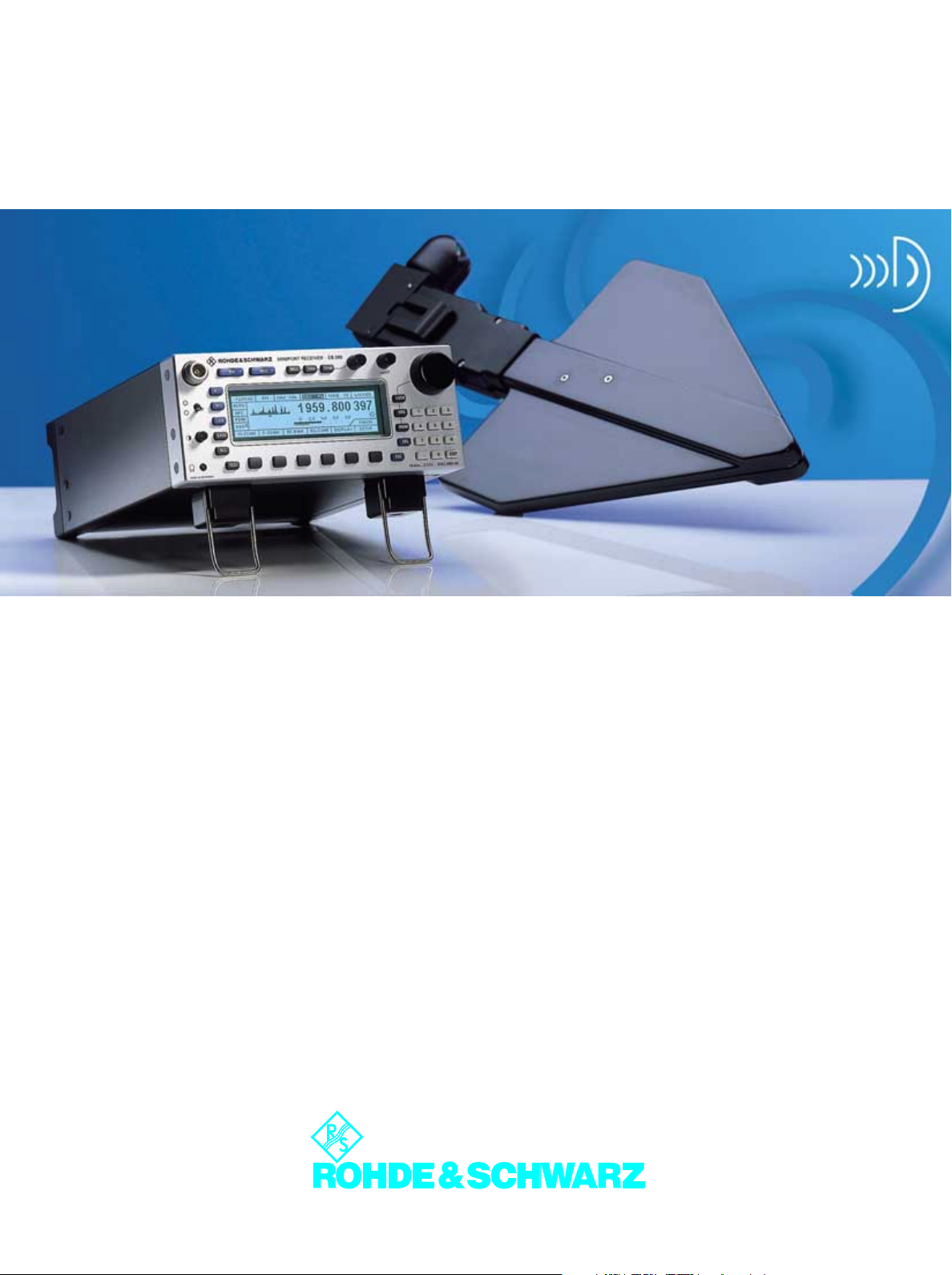
Miniport Receiver EB200
Portable monitoring from 10 kHz to 3 GHz
• Ergonomic design for on-body
operation
• Continuous frequency range
10 kHz to 3 GHz
• Detection of unlicensed transmitters
• Location of close-range to
medium-range targets with the
aid of Handheld Directional
Antenna HE200
• Digital IF section with 12 bandwidths (150 Hz to 150 kHz)
• Fast, accurate level indication
across 110 dB dynamic range
•Scanning modes
– Frequency scanning
– Memory scanning
• Frequency spectrum (option)
• IF panorama display (option)
• Remote-controllable via
RS232 CPPP or LAN (Ethernet
10Base-T)
Page 2
Brief description
Miniport Receiver EB200 with Active
Directional Antenna HE200 is a portable unit for radiomonitoring in the
wide frequency range from 10 kHz to
3 GHz. Whether used for monitoring
In case of power supply interruption,
all the data is stored. Operation can
thus be resumed immediately after the
power supply is restored.
• Location of close-range to medium-
range targets with the aid of Handheld Directional Antenna HE200
• Detection of undesired emissions
including pulsed emissions
• Detection of unlicensed transmitters
communicating illegally or interfering with licensed transmission
emissions, detecting interference or
locating mini-transmitters irrespective
of their position, EB200 offers features
unrivalled in its class. The favourably
priced and compact receiver with LAN
interface may also be used in computer-based stationary systems.
The EB200 is characterized by high
input sensitivity and frequency setting
accuracy throughout the frequency
range from 10 kHz to 3 GHz.
Its small dimensions and low weight as
well as a sturdy, pickup-proof die-cast
aluminium housing with well-protected
integrated operating elements make
the EB200 ideal for use in places
which cannot be reached with a vehicle. Its low power consumption permits
battery operation typically of four
hours. The EB200 battery pack is easily accessible and can be exchanged
quickly.
EB200 fulfils the following tasks:
• Monitoring of given frequencies,
eg storage of 1 to 1000 frequencies, squelch setting, constant monitoring of one frequency or cyclical
scanning of several frequencies
• Searching in a frequency range
with freely selectable start and stop
frequency and step widths of
1 kHz to 9.999 MHz
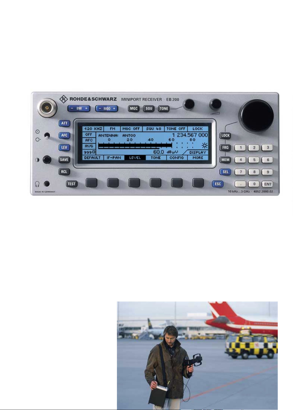
EB200 and HE200: ergonomic design for on-body operation
• Protection against tapping by detecting miniature spy transmitters
(bugs)
• Monitoring of one's own radio exercises in a service band
• Monitoring of selected transmissions
• Remote-controlled operation via
modem and PC in coverage measurement and monitoring systems
2 Miniport Receiver EB200
Page 3
Digital IF section
The EB200 covers the wide frequency
range from 10 kHz to 3 GHz. Processing all signals available with optimum
signal-to-noise ratio requires a large
number of IF bandwidths. This problem cannot be solved by means of
analog filters as space is limited. The
solution is a digital IF section in which
a wide variety of different filters can
be implemented in a relatively small
space with the aid of DSP. The EB200
has 12 IF bandwidths between
150 Hz and 150 kHz. The following
digital demodulators are available:
AM, FM, LSB, USB and CW. If the
receiver is fitted with the IF panorama
option, the number of bandwidths is
increased to 15 up to 1 MHz. Bandwidths over 150 kHz are for level and
deviation measurement as demodulation is not possible.
Scanning modes
Frequency scanning
It is possible to define a frequency
range to which a complete data set
can be allocated. In addition to
receiver settings, the following scan
parameters may be included in the
data set:
• Step width
• Signal threshold (dBµV)
• Dwell time (s)
• Hold time (s)
• Signal-controlled continuation
• Suppression (individual frequen-
cies or search ranges)
a scanning run. The content of any memory location can be transferred to
the receiver manually
using the RCL key, by turning the setting knob or
automatically by activat-
DIGI-Scan: Scan mode ...
ing the memory scanning
process.
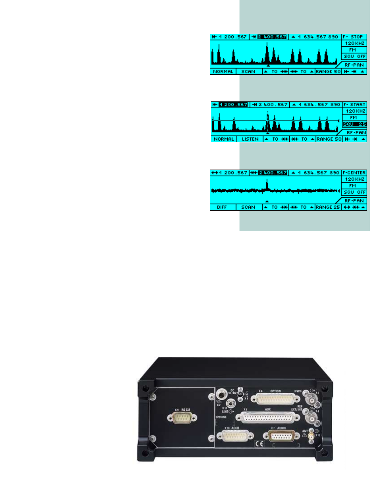
Frequency spectrum
Fitted with the frequency
spectrum (DIGI-Scan)
option, EB200 scans the
frequency range of interest
... listen mode ...
with digital control and displays the associated spectrum. Emissions detected
can be seen at a glance.
Aural monitoring of the
information is possible by
simply pressing a softkey.
EB200 then goes to the
... differential mode
DIGI-Scan listen mode. The
stored spectrum is displayed in the background, and the
emission of interest can be selected
and monitored by marking it with the
frequency cursor.
Location of miniature transmitters at
close range is possible in the differential mode of the DIGI-Scan option. In
this mode, the displayed spectrum is
stored as a reference. Current spectra
are superimposed on the reference
spectrum, and any new signals or variations in signal strength are clearly
discernible as peaks. If the measurement is made with the distance, the
field strength of transmitters at close
range varies to a greater extent than
that of transmitters located far away.
This differential display ensures fast
and reliable location of miniature
transmitters even in case of spreadspectrum transmission.
Memory scanning
The EB200 uses 1000 definable memory locations. A complete data set,
such as frequency, mode of demodulation, bandwidth, squelch level, etc,
can be assigned to each memory location. The memory content can be
edited or overwritten with the results of
Miniport Receiver EB200 3
Page 4

Overview
IF panorama
Level (zoomed)
Function
The EB200 is a superhet receiver with
a third intermediate frequency of
10.7 MHz. In spite of its compact
size, it was possible to implement an
advanced receiver concept. The
receiver input is equipped with a highpass/lowpass combination or tracking preselection, as required, to
reduce the signal sum load. Intermodulation suppression equals that of
many receivers used in stationary
applications.
The low degree of oscillator reradiation is a result of large-scale filtering. A
modern synthesizer concept featuring
very low phase noise permits switching times of less than 3 ms. Effective
frequency and memory scanning is
thus possible.
For every task
the optimized view ...
State-of-the-art design
The receiver is designed for both
mobile and stationary operation.
Careful screening and filters in all the
input and output lines guarantee
extremely low spurious as well as high
interference rejection.
BITE
The receiver is permanently monitored
by built-in test equipment. If deviations
from the nominal are detected, an
error message is output with a code
informing on the type of fault.
Serviceability
Modern design and the use of plug-in
modules guarantee short repair times.
All the modules may be exchanged
without any recalibration or adjustments being required.
Remote control
All the receiver functions can be
remote-controlled via the serial
RS232C interface of a controller. For
measurement tasks, the LAN option
provides a hundred times faster speed
as well as easy connection and control
of multiple receivers from a PC. With
these different versions the user can
select the type of remote control to suit
his tasks.
Operation
The operational concept of the EB200
meets all the requirements of a modern
radiomonitoring receiver, ie all the
essential functions, such as modes of
demodulation, bandwidths, etc, can
be set via labelled keys directly.
Settings that are not used during current operation are available in submenus. The hierarchy of menu control
is implemented according to priorities
for ease of use.
Certified Quality System
ISO 9001
DQS REG. NO 1954-04
4 Miniport Receiver EB200
Page 5

Handheld Directional Antennas
Uses
The handy and highly broadband
Active Directional Antenna HE200 in
conjunction with portable receivers
(eg EB200) is ideal for locating transmitting and interfering sources. The
HE200HF
10 kHz bis 20 MHz
10 kHz to 20 MHz
HE200
▲
▲
▲
direction is found by pointing the
antenna towards the direction of maximum signal voltage. The overall frequency range from 0.01 MHz to
3000 MHz is covered by 4 exchangeable broadband antenna modules
each with a distinct directional pattern. A low-noise broadband amplifier
may be added to increase sensitivity
in the active mode. The amplifier is
bypassed in the passive mode and in
this case the antenna may also be
used in the vicinity of strong transmitters.
• Unambiguous direction finding*),
ie directional pattern with the receive maximum pointing to the
front in the frequency range
20 MHz to 3 GHz
• The maximum of the antenna output signal serves as a direction
criterion (maximum direction
finding)
• Handy size despite very wide
broadband characteristic
• Weight is kept to a minimum due
to material used and antenna
design
• Can be used for vertically and
horizontally polarized signals in
the frequency range 20 MHz to
3GHz
• Wide dynamic range due to
switchable passive and active
mode
*) For the unambiguous determination of the angle
of incidence of a signal, at least two different
sites are required. The transmitter is to be located
at the intersection point of the DF beams.
20 MHz bis 200 MHz
20 MHz to 200 MHz
200 MHz to 500 MHz
200 MHz bis 500 MHz
Description
A broadband cardioid directional pattern is obtained in the frequency
ranges 20 MHz to 200 MHz and
200 MHz to 500 MHz by using a
loaded loop antenna in two different
sizes. A log-periodic dipole antenna
covers the range 500 MHz to
3000 MHz with a directional pattern.
A loop antenna is available as an
option for the lower frequency range
of 0.01 MHz to 20 MHz.
The four RF modules can be
exchanged by means of a quickrelease catch provided at the supply
and display unit. The supply and display unit comprises the following modules:
• Antenna electronics made up of
low-noise amplifier as well as active/passive switchover circuit
• Active/passive switchover by
means of relay
The low-noise amplifier is bypassed in
passive mode and has no supply voltage. Passive mode is thus also possible without batteries and external voltage supply. The antenna should only
be switched to active mode if there are
no strong transmitters in close vicinity
and if the sensitivity of the receiving
system (antenna with receiver) in the
passive mode is not sufficient to detect
the signal. When the amplifier is activated, a yellow LED on the rear of the
supply and display unit indicates
whether the supply voltage from battery or external source has fallen
below the permissible range.
0,5 GHz bis 3 GHz
0.5 GHz to 3 GHz
Miniport Receiver EB200 5
Page 6

Specifications
Frequency range 10 kHz to 3 GHz
Frequency setting
via keypad or rollkey 1 kHz, 100 Hz, 10 Hz, 1 Hz or in
Frequency accuracy
Aging
Synthesizer setting time
Oscillator phase noise
Antenna input N socket, 50
Oscillator reradiation
RF attenuation 30 dB, man. or autom., switchable
Input selection
100 kHz to 20 MHz highpass/lowpass
20 MHz to 1.5 GHz tracking preselection
1.5 GHz to 3 GHz highpass/lowpass
Interference rejection, nonlinearities
Image frequency rejection
IF rejection
2nd order intercept point typ. 40 dBm
3rd order intercept point typ. 2 dBm
Internal spurious signals
Sensitivity
Overall noise figure
(including AF section)
20 MHz to 650 MHz
650 MHz to 1500 MHz
1500 MHz to 2700 MHz
2700 MHz to 3000 MHz
Signal-to-noise ratio measurement with telephone filter to
AM, bandwidth 6 kHz,
= 1 kHz, m = 0.5
f
mod
20 MHz to 2700 MHz, V = 1 µV
2.7 GHz to 3 GHz, V = 1.3 µV
FM, bandwidth 15 kHz,
f
= 1 kHz, deviation = 5 kHz
mod
20 MHz to 2700 MHz, V = 1 µV
2.7 GHz to 3 GHz, V = 1.3 µV
Demodulation AM, FM, USB, LSB, CW
IF bandwidths 12 (150/300/600 Hz/1.5/2.4/6/
IF bandwidths for level and
deviation indication 15 (150 Hz to 1 MHz) only with
Squelch signal-controlled, can be set from
Gain control AGC, MGC
IF control 80 dB
RF + IF control 110 dB
AFC digital retuning for signals unstable in
Deviation indication graphical with tuning label
Signal level indication graphical as level line or numerical
IF panorama display (option SU) internal module, ranges 25, 50, 100,
Scan characteristics
Automatic memory scan 1000 definable memory locations to
Frequency scan START/STOP/STEP definition with
Inputs/outputs
Digital IF output serial data (clock, data, frame)
Bidirectional reference frequency
connectors 10 MHz, BNC
in 0.1 V to 1 V; R
out 0 dBm, Ro = 50 Ω
I/Q output (digital) AF signal, 2 x 16 bit
IF 10.7 MHz, wideband ±5 MHz uncontrolled for external
selectable increments
≤±1.5x10
≤±0.5x10
≤3 ms
−6
(−10 °C to + 55°C)
−6
/year
≤−100 dBc/Hz at 10 kHz offset
Ω , VSWR ≤3; SMA con-
nector for rackmounting at rear panel
≤−107 dBm
≥70 dB, typ. 80 dB
≥70 dB, typ. 80 dB
≤−107 dBm
≤14 dB, typ. 12 dB
≤15.5 dB
≤14 dB, typ. 12 dB
≤15 dB, typ. 13 dB
CCITT
≥10 dB
≥10 dB
≥25 dB
≥25 dB
9/15/30/50/120/150 kHz)
IF Panoramic Unit EB200SU
−10 dBµV to +100 dBµV
frequency
−10 dBµV to +100 dBµV, acoustic
from
indication by level tone
200, 500, 1000 kHz
each of which a complete data set can
be allocated
receiving data set
up to 256 ksps: 2 x 16 bit
= 500 Ω
i
panoramic display
AF output, balanced 600 Ω , 0 dBm
Loudspeaker output 8
Headphones output via volume control
Ω , 500 mW
Output log. signal level 0 V to +4.5 V
BITE monitoring of test signals by means of
loop test
Data interface RS232 C PPP
Option LAN (Ethernet 10Base-T)
General data
Operating temperature range
Rated temperature range 0°C to +50°C
Storage temperature range
Humidity max. 95%, cyclic test 25/55°C
Shock to DIN IEC 68-2-27
Vibration (sinewave) to DIN IEC 68-2-6 (MIL-T-28800D),
Vibration (noise) to DIN IEC 68-2-36, 10 Hz to 500 Hz,
Electromagnetic compatibility (EMC) EN50081/82-1,82-2, MIL-STD-461,
Power supply battery pack (typ. 6 h operation) or
Dimensions (W x H x D) 210 mm x 88 mm x 270 mm
Weight (without battery pack) 4 kg
Battery pack 1.5 kg
−10°C to +55 °C
−40°C to +70 °C
(MIL-STD-810D, MIL-T-28800D), 40 g,
shock spectrum 45 Hz to 2 kHz
5 Hz to 55 Hz, 0.15 mm amplitude
1.9 g (rms)
CE03; RE02 and RS03
DC 10 V to 30 V (max. 22 W)
½19" x 2 HU
Directional antennas HE200/HE200HF
Frequency range 0.01 MHz to 3000 MHz
Antenna modules 20 MHz to 3000 MHz, with 3 plug-in
20 MHz to 200 MHz loaded loop antenna
200 MHz to 500 MHz loaded loop antenna
500 MHz to 3000 MHz log-periodic antenna
Option
0.01 MHz to 20 MHz loop antenna
Polarization vertical for all antenna modules, hori-
Loop antenna
0.01 MHz to 20 MHz direction finding for horizontally polar-
Nominal impedance 50
SWR <2.5 typ.
RF output 1 m cable with N connector
Gain for typical values see page 7
Antenna factor for typical values see page 7
Field-strength sensitivity for typical values see page 7
Linearity of amplifier IP3, typ. 19 dBm (battery voltage 6 V,
Current drain 55 mA in active mode
Power supply in handle, 4 x 1.5 V mignon cell R6
Dimensions (W x H x D) 470 mm x 360 mm x 180 mm
General data
Operating temperature range
Rated temperature range
Storage temperature range
Vibration resistance random 10 Hz to 300 Hz: 0.01 g
Shock resistance max. 40 g, crossover frequency 45 Hz
Weig ht s:
Supply and display unit 0.5 kg
with adapters and compass 0.65 kg
RF modules
20 MHz to 200 MHz 0.55 kg
200 MHz to 500 MHz 0.3 kg
500 MHz to 3000 MHz 0.45 kg
0.01 MHz to 20 MHz 0.4 kg
antennas
zontal polarization by turning the longitudinal antenna axis by 90°
ized signals not possible because of
circular vertical pattern of system
Ω
25°C)
0 mA in passive mode
(in transport case)
−30°C to +60 °C active/passive mode
−10°C to +50 °C active mode
−30°C to +60 °C passive mode
−30°C to +60 °C
300 Hz to 500 Hz: 0.003 g
every 30 minutes in 3 orthogonal
axes; acceleration approx. 1.9 g rms
2
/Hz,
2
/Hz,
in 3 orthogonal axes
6 Miniport Receiver EB200
Page 7

Gain,
5
7.5
10
12.5
15
17.5
20
22.5
25
27.5
30
10
10
2
10
3
10
4
dB (µV/m)
Antenna module
200 to 500 MHz
Antenna module
0.5 to 3.0 GHz
Antenna module
20 to 200 MHz
Frequency in MHz
S/N = 1 bandwidth 10 kHz receiver noise figure 15 dB
dB
10
5
0
10
15
20
25
30
35
40
45
50
5
passive mode
Antenna module
20 to 200 MHz
10
2
10
Antenna module
200 to 500 MHz
Frequency in MHz
Antenna module
0.5 to 3.0 GHz
3
10
Gain, active mode
dB
20
15
10
5
0
5
Antenna module
20 to 200 MHz
10
15
20
25
4
10
30
10
2
10
Antenna module
200 to 500 MHz
Frequency in MHz
10
Antenna module
0.5 to 3.0 GHz
3
4
10
Antenna factor,
45
dB/m
40
35
30
25
20
15
10
passive mode
Antenna module
20 to 200 MHz
Antenna module
200 to 500 MHz
2
10
Frequency in MHz
Field-strength sensitivity, passive mode
3
10
Antenna module
0.5 to 3.0 GHz
4
10
Antenna factor, active mode
35
dB/m
30
25
20
15
Antenna module
20 to 200 MHz
10
5
10
Field-strength sensitivity, active mode
S/N = 1 bandwidth 10 kHz receiver noise figure 15 dB
25
dB (µV/m)
20
15
10
Antenna module
20 to 200 MHz
5
Antenna module
200 to 500 MHz
2
10
Frequency in MHz
Antenna module
200 to 500 MHz
Antenna module
0.5 to 3.0 GHz
3
10
Antenna module
0.5 to 3.0 GHz
4
10
Ordering information
EB200
Miniport Receiver EB200 4052.2000.02
Accessory supplied:
power supply 110/230 V, 50/60 Hz
Recommended extras
Carrying Case (telescopic antenna, headset,
belt and space for EB200, battery pack) EB200SC 4052.9304.02
Battery Pack EB200BP 4052.4102.02
Internal IF Panoramic Unit EB200SU 4052.3206.02
RF Spectrum DIGI-Scan EB200DS 4052.9604.02
LAN Interface EB200R4 4052.9156.02
Rack Adapter EB200ZZ 4052.8250.02
0
5
10
2
10
Frequency in MHz
3
10
4
10
Handheld directional antennas
HE200 20 MHz to 3 GHz 4050.3509.02
HE200 comprises
Loaded loop antenna 20 MHz to 200 MHz 0701.5702.00
Loaded loop antenna 200 MHz to 500 MHz 0701.5354.00
Log-periodic antenna 500 MHz to 3 GHz 4050.3609.02
Accessory supplied: carrying case
Option HE200HF
Loop antenna 0.01 MHz to 20 MHz 4051.4009.02
Adapter and compass fitted to the supply and display unit when delivered.
Miniport Receiver EB200 7
Page 8

Data without tolerances: typical values Printed in Germany 1098/0102 (U we)
⋅
Subject to change
⋅
Trade names are trademarks of the owners
⋅
Miniport Receiver EB200
⋅
ROHDE & SCHWARZ GmbH & Co. KG ⋅ Muehldorfstrasse 15 ⋅ 81671 Munich, Germany
P.O.B. 8014 69 ⋅ 81614 Munich, Germany ⋅ Telephone +4989 4129-0 ⋅ Fax +4989 4129-13247 ⋅ www.rohde-schwarz.com
PD 0757.3728.22
 Loading...