

Page 1
SpycerBox Ultra/Fl ex Hardware Guide (Versio n 3.0)
Storage Solution
SpycerBox
Ultra/Flex
Hardware Guide
Page 2

Page 3

SpycerBox Ultra/Flex
Hardware Guide
Introduction
Overview
Installation
Operation
Maintenance
Appendix
Index
1
2
3
4
5
A
I
Page 4

Hardware Guide Version 3.0 for the SpycerBox Ultra (SpycerBox Ultra II Revision 1.2) and SpycerBox Flex (SpycerBox Flex Revision 1.1)
Copyright © 2012 by Rohde & Schwarz DVS GmbH, Hanover. All rights reserved.
The manuals as well as the soft- and/or hardware described here and all their constituent parts are
protected by copyright. Without the express permission of Rohde & Schwarz DVS GmbH any form
of use which goes beyond the narrow bounds prescribed by copyright legislation is prohibited and
liable to prosecution.
This particularly applies to duplication, copying, translation, processing, evaluation, publishing, and
storing and/or processing in an electronic system.
Specifications and data may change without notice. We offer no guarantee that this documentation
is correct and/or complete. In no event shall Rohde & Schwarz DVS GmbH be liable for any damages
whatsoever (including without limitation any special, indirect or consequential damages, and damages resulting from loss of use, data or profits, or business interruption) arising out of the use of or
inability to use the hardware, software and/or manual materials.
Those parts of this documentation that describe optional software or hardware features usually contain a corresponding note. Anyway, a lack of this note does not mean any commitment from
Rohde & Schwarz DVS GmbH.
DVS and Spycer are registered trademarks of Rohde & Schwarz DVS GmbH. FireWire is a trademark
of Apple Inc., registered in the U.S. and other countries. Linux is a registered trademark of Linus
Torvalds.
Any other product names mentioned in this documentation may be trademarks or registered trademarks of their respective owners and as such are subject to the usual statutory provisions.
Page 5

Headquarters:
Rohde & Schwarz DVS GmbH
Krepenstr. 8
30165 Hannover
GERMANY
Phone: +49-511-67807-0
Fax: +49-511-630070
E-mail: info.dvs@rohde-schwarz.com
Internet: http://www.dvs.de
Support:
Phone: +49-511-67807-125
Fax: +49-511-371985
E-mail: service.dvs@rohde-schwarz.com
Page 6

Page 7
Registration Form
PLEASE SEND TO:
Rohde & Schwarz DVS GmbH
Krepenstr. 8
30165 Hannover
GERMANY
Fax: +49-511-630070
Dear customer,
this product was developed and tested thoroughly. Unfortunately, the possibility of problems and errors can never
be ruled out. To support us in helping you as fast as possible if such a case occurs, please fill in this registration form
and send or fax it to the address on the right.
You may also use our online registration form which can be accessed from the following
internet page: http://www.dvs.de/support/support-login.html
Customer
Name:
Company:
Contact:
Address:
Phone:
Fax:
Vendor:
SpycerBox Ultra/Flex
Serial No.:
Remarks:
Connected devices
(used network connections, connected storages, file systems, etc.)
Page 8

Page 9

Contents
C
1 Introduction ...............................................................................1-1
1.1 Overview .................................................................................1-2
1.2 Target Group ...........................................................................1-3
1.3 Conventions Used in this User Guide .....................................1-4
1.4 Safety Instructions .................................................................. 1-5
1.5 Important Notes ......................................................................1-7
2 Overview......................................................................................2-1
2.1 Variants: SpycerBox Ultra and SpycerBox Flex .......................2-2
2.2 Overview of the Front.............................................................. 2-2
2.2.1 The Front of the System .................................................2-2
2.2.2 DVD Drive .....................................................................2-3
2.2.3 HDD LEDs ..................................................................... 2-4
2.2.4 Faceplate ......................................................................2-5
2.2.5 Hard Disk Array ............................................................. 2-6
2.2.6 Operation Items ............................................................. 2-9
2.3 Overview of the Rear.............................................................2-11
2.3.1 The Rear of the System ................................................ 2-11
2.3.2 System Disk Array .......................................................2-12
2.3.3 ATX Connector Panel....................................................2-13
2.3.4 Power Supply ..............................................................2-14
2.3.5 Slot Panel Connectors ..................................................2-15
2.4 Battery Backup Unit .............................................................. 2-17
3 Installation .................................................................................. 3-1
3.1 System Setup .......................................................................... 3-1
3.2 Note about the Network Installation ....................................... 3-2
i
Page 10

SpycerBox Ultra/Flex Hardware Guide
4 Operation .....................................................................................4-1
4.1 Starting the System .................................................................4-2
4.2 DVS Configuration Tool ...........................................................4-3
4.3 Shutting Down the System .....................................................4-4
5 Maintenance ..............................................................................5-1
5.1 Hard Disk Maintenance ...........................................................5-2
5.1.1 Introduction to RAID ......................................................5-2
5.1.2 Identifying a Broken Hard Disk ........................................5-4
5.1.3 Replacing a Hard Disk ....................................................5-5
5.2 Opening and Closing the Casing .............................................5-8
5.2.1 Opening the Casing ........................................................5-8
5.2.2 Closing the Casing .........................................................5-8
5.3 Fan Maintenance .....................................................................5-9
5.4 Controller Maintenance .........................................................5-12
5.5 Power Supply Maintenance...................................................5-14
5.6 Backup or Recovery of the System Disk ...............................5-16
5.6.1 Creating a Backup Image of the System Disk .................5-16
5.6.2 Restoring the System Disk ............................................5-18
5.7 Removal of the Faceplate ......................................................5-20
A Appendix..................................................................................... A-1
A.1 Troubleshooting ...................................................................... A-2
A.2 Technical Data ........................................................................ A-4
A.2.1 General Technical Data .................................................. A-4
A.2.2 Dimensions .................................................................. A-5
A.3 Packing Instructions ............................................................... A-6
A.4 Conformity Declarations ......................................................... A-8
A.4.1 RoHS Compliance ......................................................... A-8
A.4.2 EC Declaration of Conformity (CE Marking) ..................... A-8
A.4.3 FCC Compliance Statement ........................................... A-8
I Index ...............................................................................................I-1
ii
Page 11
Introduction
This documentation describes how to use the hardware of the SpycerBox manufactured by DVS. The SpycerBox is a multi-purpose storage
as well as server device delivered with several data management tools.
It is the ideal solution for users at broadcast and post production facilities who want to make the most of their file-based workflows. The
SpycerBox can be used, for example, …
– … as a high-performance automated backup and archiving solu-
tion,
– … as a powerful file server with proxy clip generation, or
– … as an NAS solution for a network.
1
1
2
Together with the hardware of the SpycerBox you also receive the
SpycerBox software, an extended version of DVS’s data management
software Spycer. With the SpycerBox software you can, for instance,
automatically create low-resolution proxy video clips of the content on
the local or a connected storage, defragment an SNFS storage such as
a SAN, or perform scheduled maintenance tasks automatically in your
network.
The SpycerBox hardware uses Linux as its operating system and can be
delivered with various storage capacities. Furthermore, several connection possibilities are optionally available to integrate the system seamlessly into your workflows.
The SpycerBox can be delivered in two hardware variants: SpycerBox
Ultra using 3.5" hard disks (normally 24 pcs.) and providing a storage
capacity of up to 72 TB, and SpycerBox Flex using 2.5" hard disks (normally 48 pcs.) with up to 43.2 TB of storage capacity.
3
4
5
A
I
1-1
Page 12
SpycerBox Ultra/Flex Hardware Guide
1.1 Overview
This guide informs you about the installation of the SpycerBox hardware, its operation as well as all connection possibilities. Furthermore,
it describes maintenance tasks that you may carry out on your own.
The chapters contain the following information:
Chapter 1 Begins with a short introduction to the Spycer-
Chapter 2 This chapter gives a front and rear overview of
Box, followed by a note regarding the audience
this manual is written for and an explanation of
the conventions used in this manual. Furthermore, it provides safety instructions that you
must adhere to and some important notes that
you should observe.
the system detailing all items, connectors and
interfaces. Additionally, it contains some further information, for example, about the battery backup unit.
Chapter 3 Describes the hardware installation of the DVS
system.
Chapter 4 Explains how to operate the DVS system, i.e.
how to start and shut down the device. Additionally, the DVS Configuration Tool is described briefly.
Chapter 5 Details maintenance work, for example, in case
of a hard disk, fan or power supply unit failure.
Appendix Provides technical details and general informa-
tion about the hardware of the DVS system.
Furthermore, it gives hints how to resolve irregularities during operation.
Index This chapter facilitates the search for specific
terms.
1-2
Page 13

1.2 Target Group
To use this manual you should know how to handle computer equipment. Furthermore, to connect the DVS system to a network or a SAN
storage you should have experience as a network administrator and
know how to set up the required network connections on the installation site in hard- as well as software.
When performing maintenance tasks on the hardware of the DVS system, you must be qualified to work on, repair and test electrical equipment.
Introduction
1
2
3
4
5
A
I
1-3
Page 14
SpycerBox Ultra/Flex Hardware Guide
1.3 Conventions Used in this User Guide
The following typographical conventions will be used in this documentation:
Texts preceded by this symbol describe activities that you must per-
form in the order indicated.
– Texts preceded by this symbol are parts of a list.
Texts preceded by this symbol are general notes intended to facilitate work and help avoid errors.
You must pay particular attention to text that follows this symbol to avoid errors and possible resulting damages thereof.
Texts following this symbol you must pay particular attention to to avoid dangers and personal injuries.
“ ” Texts enclosed by quotation marks are references to other man-
uals, guides, chapters, or sections.
Entry Indicates entries to be made at a command line
or an output of a program on the screen
[Key] A key on a keyboard
Keyboard Shortcuts
To perform options or procedures with the keyboard often requires a simultaneous pressing of two keys.
Example:
[Ctrl + F1] If this is given, hold down the [Ctrl] key and
press simultaneously the [F1] key.
1-4
Page 15
1.4 Safety Instructions
To use the SpycerBox correctly please heed the following:
Please read the following safety instructions carefully before
attempting any installation and/or performing any work on the
SpycerBox hardware.
If the DVS system is not used in compliance with the safety
instructions, the warranty and all resulting liability claims will
be void.
General
The SpycerBox has been built according to the applying safety regulations. To minimize the possibility of a faulty operation of the device all
manuals and guides must be available at all times at the operation site.
Before installing and/or using the DVS system the manuals and guides
delivered with it must be read and observed.
Introduction
1
– Use the DVS system only in apparent good technical order.
– The hardware of the DVS system works with voltages that can be
hazardous to your health. Never work on the system or access its
interior with the power cable(s) being plugged in. Make sure the
power supply is disconnected from the components you intend to
work on.
– Computer hardware contains components that are sensitive to elec-
trostatic discharge. If you touch them without precautionary mea-
sures, they can be destroyed. Use a wrist strap connected to
ground when accessing electronic parts and take care of grounding
the system. Avoid touching the internal components of the DVS
system whenever possible.
– Computer hardware contains components that are sensitive to
changing voltages. Connecting or disconnecting the DVS system to
or from peripheral hardware while any of them is switched on may
damage the hardware. Switch off all peripheral hardware before
connecting or disconnecting anything.
– Use, store and transport the DVS system only in compliance with
the technical data laid out in section “Technical Data” on page A-4.
– If fluids or solid objects get inside the casing, the DVS system must
be disconnected from the power supply immediately. Before using
the DVS system again, it has to be checked by authorized service
personnel.
– Only use a damp tissue without any cleaning agents to clean the
casing.
– The DVS system must not be misused, abused, physically dam-
aged, neglected, exposed to fire, water or excessive changes in the
climate or temperature, or operated outside maximum rating.
– Do not perform any changes or extensions to the DVS system
whatsoever.
2
3
4
5
A
I
1-5
Page 16

SpycerBox Ultra/Flex Hardware Guide
Transportation
The SpycerBox is a very sensitive device. Especially the hard disks of
the system must be handled with great care. Therefore, observe in case
of transportation:
– Handle the DVS system with great care.
– Always use the original packing or a similar structured packing for
transportation as detailed in section “Packing Instructions” on
page A-6.
– Avoid shocks or vibrations during transport. For longer distances it
is recommended to use a lifting truck.
– Keep the DVS system as a transportation good dry.
– In the warranty period you have to keep the original packing and
use it in case of transportation.
Environmental Conditions
For error-free working and a long service life the SpycerBox needs
some basic environmental conditions:
– Do not expose the DVS system to sources of heat, such as direct
sunlight or a radiator.
– Do not cover or obstruct the ventilation holes of the system.
– When installing the DVS system in a rack, take care that warmed up
air is conducted to the rear of the rack and properly vented away.
– Avoid areas with high humidity or dust. Best operating conditions
are given in an air-conditioned site.
– Do not expose the DVS system to strong electric or magnetic fields.
– Avoid areas where the DVS system will be subject to vibrations or
shocks.
1-6
Page 17
1.5 Important Notes
The following provides information about warranty, a note about the
conformity of the product and some other general information.
Warranty Information
This product is warranted to be free of defects in materials and workmanship for a period of one year from the date of purchase. DVS extends this Limited Warranty to the original purchaser.
You have to keep the original packing and use it in case of
transportation. Otherwise this warranty will be void.
In the event of a defect or failure to confirm to this Limited Warranty,
DVS will repair or replace the product without charge. In order to make
a claim under this Limited Warranty, the purchaser must notify DVS or
their representative in writing of the product failure. In this Limited Warranty the customer must upon DVS’s request return the product to the
place of purchase or send the defective device to a given address for
the necessary repairs to be performed. In the warranty period the customer must keep the original packing and pack the DVS product in it in
case of a product return. If the customer is not satisfied with the repair,
DVS will have the option to either attempt a further repair, exchange the
product or refund the purchase price.
Introduction
1
2
3
This warranty does not cover:
– Products not developed by Rohde & Schwarz DVS GmbH.
– Products not used in compliance with the safety instructions
detailed in section “Safety Instructions” on page 1-5.
– Products on which warranty stickers or product serial numbers
have been removed, altered or rendered illegible.
– The costs of installations, removals, transportations, or reinstalla-
tions.
– Costs for transportation damages.
– Damages caused to any other item.
– Any special, indirect or consequential damages, and damages
resulting from loss of use, data or profits, or business interruption.
Declaration of Conformity
This product has been tested according to
the applying national and international directives and regulations. Further information
about this can be found in section “Conformity Declarations” on page A-8.
4
5
A
I
1-7
Page 18
SpycerBox Ultra/Flex Hardware Guide
Product Disposal (B2B)
Used electrical and electronic products should not be disposed of with general household waste. At the end of its
service life you may return the DVS product after appropriate prior notification to either your local distributor or
DVS in Germany. DVS will then take the device free of
charge to a waste disposal organization which will recycle and reuse it environmental friendly.
General Notes
Please observe the following general important notes:
Leave about 10 to 15% of the overall main storage capacity
empty of data for performance reasons.
Your DVS system has been tested thoroughly and is very reliable. However, because of the vast amount of third-party software available, its reactions on the installation of such could
not be tested. The installation of third-party software may disrupt the real-time capability and/or limit the functionality of
your system.
1-8
Page 19

Overview
This chapter provides a detailed overview of the hardware of the DVS
system. First the different hardware variants of system will be explained. After this it will be shown in a front and a rear view and all its
parts and connectors will be described. The chapter will be concluded
with a description of the battery backup unit installed inside the system.
2
1
2
3
4
5
A
I
2-1
Page 20
SpycerBox Ultra/Flex Hardware Guide
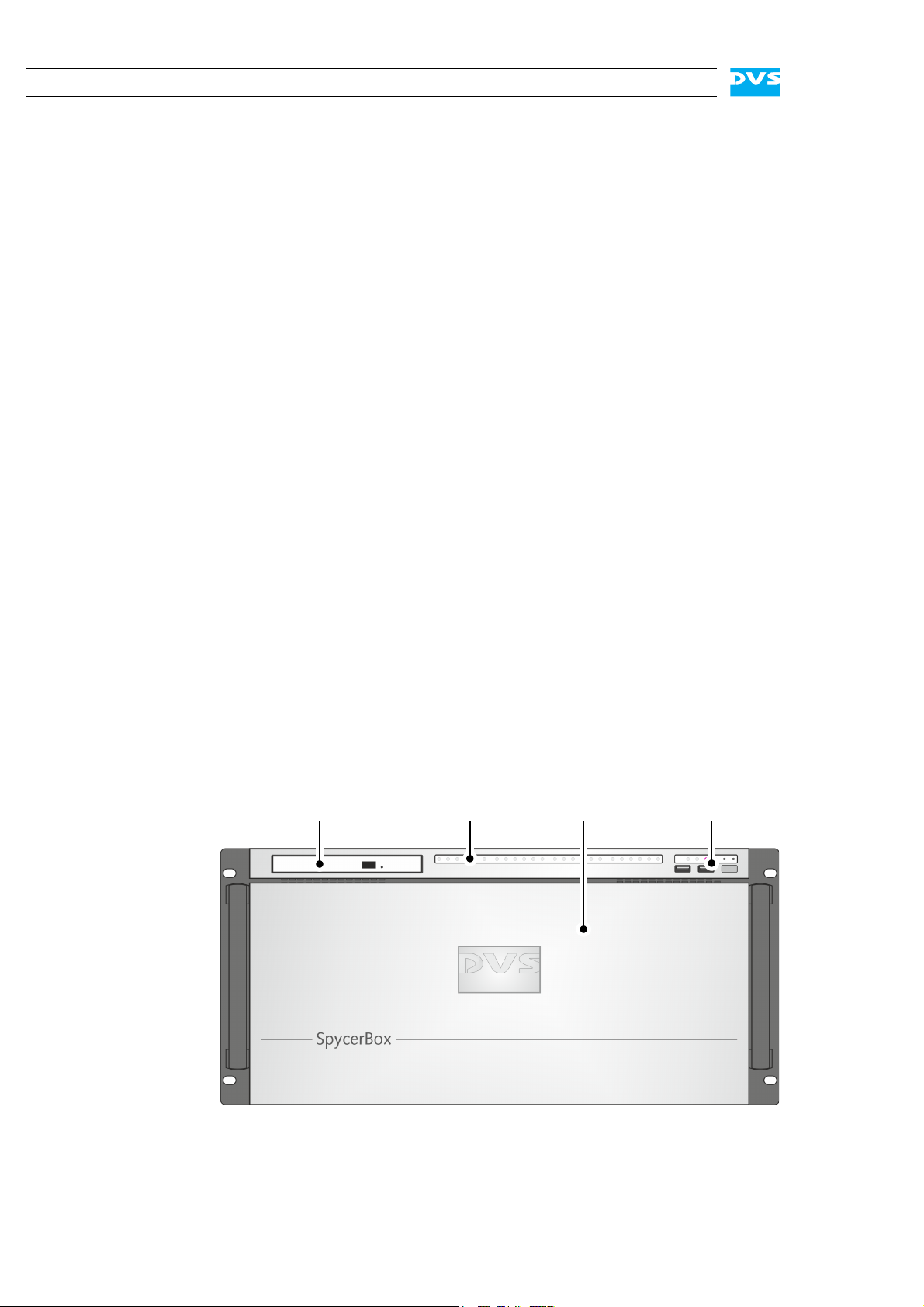
DVD drive
faceplate/
HDD LEDs operation items
hard disk array
2.1 Variants: SpycerBox Ultra and SpycerBox Flex
The SpycerBox can be delivered in two different hardware variants depending on, for example, the amount of the storage or the performance
that is required. The following variants are available:
– SpycerBox Ultra using 3.5" hard disks (normally 24 pcs.) and pro-
viding a storage capacity of up to 72 TB.
– SpycerBox Flex using 2.5" hard disks (normally 48 pcs.) for up to
43.2 TB of storage capacity.
Apart from the hard disk array where the hard disks are installed (see
section “Hard Disk Array” on page 2-6) the two variants are in most respects identical. Whereever required the specialities of these variants
will be detailed in this document.
2.2 Overview of the Front
This section gives an overview of the front of the DVS system. After an
overall overview of the front the DVD drive is described first, followed
by details about the HDD LEDs. After this the faceplate and the hard
disk array of the system as well as the operation items will be explained.
2.2.1 The Front of the System
This section provides an overview of the front of the system:
2-2
Figure 2-1: Overview of the front
Page 21
Overview
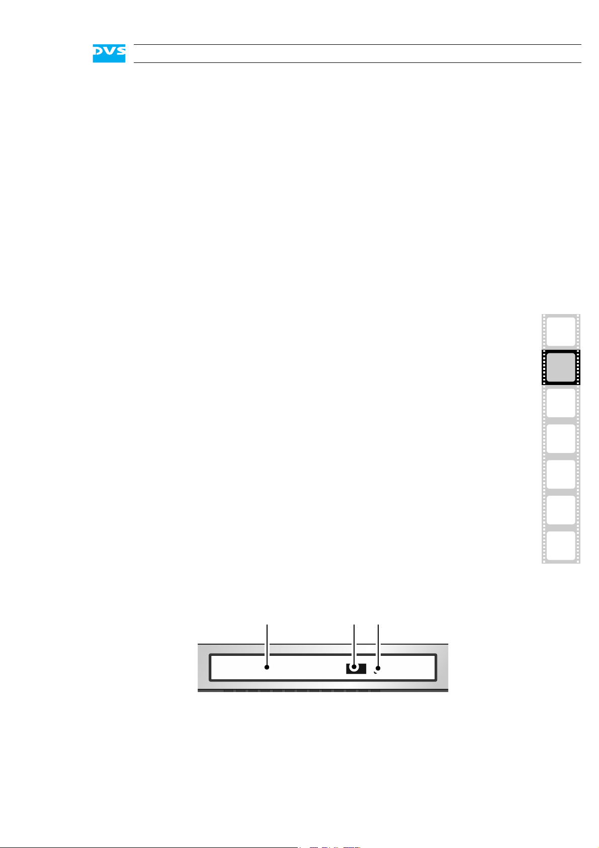
DVD tray DVD eject emergency eject
DVD drive The DVD drive can be used, for example, for soft-
ware installations. Further information about the
DVD drive can be found in section “DVD Drive” on
page 2-3.
HDD LEDs The upper part of the front is equipped with LEDs
that indicate the statuses (activities) of the hard
disks of the hard disk array. Further information
about the LEDs and their meaning can be found in
section “HDD LEDs” on page 2-4.
faceplate/
hard disk array
operation items With the operation items the system can be con-
2.2.2 DVD Drive
The system is equipped with a DVD drive which can be used for service
purposes or to install additional software. It also provides burning capability.
The faceplate covers the hard disk array. If you
need access to one of the hard disks, for example,
to replace it, it can be lifted. The faceplate will be
described in more detail in section “Faceplate” on
page 2-5.
The hard disk array contains the main storage hard
disks which can be used to store video, audio or
backup material. All disks can be replaced easily in
case of failure. The disk array is described in more
detail in section “Hard Disk Array” on page 2-6.
trolled (e.g. turned on or off). Additionally, they offer some LEDs that allow you to assess the state of
the DVS system as well as USB connectors for an
easy connectivity of additional devices such as
memory sticks. Further information about the operation items can be found in section “Operation
Items” on page 2-9.
1
2
3
4
5
A
I
Figure 2-2: Overview of DVD drive
DVD tray The DVD tray holds the CD or DVD.
2-3
Page 22
SpycerBox Ultra/Flex Hardware Guide
A
1
BCD
234 1234 1234 1234
1111
2222
3333
4444
LEDs:
hard disks:
5 5 5 5
5555
ABCD
66 6 6
6666
DVD eject Opens the DVD tray when the system is turned
emergency eject You can open the DVD tray with the system
For further information regarding the operation of the drive, please refer
to the original manufacturer’s documentation.
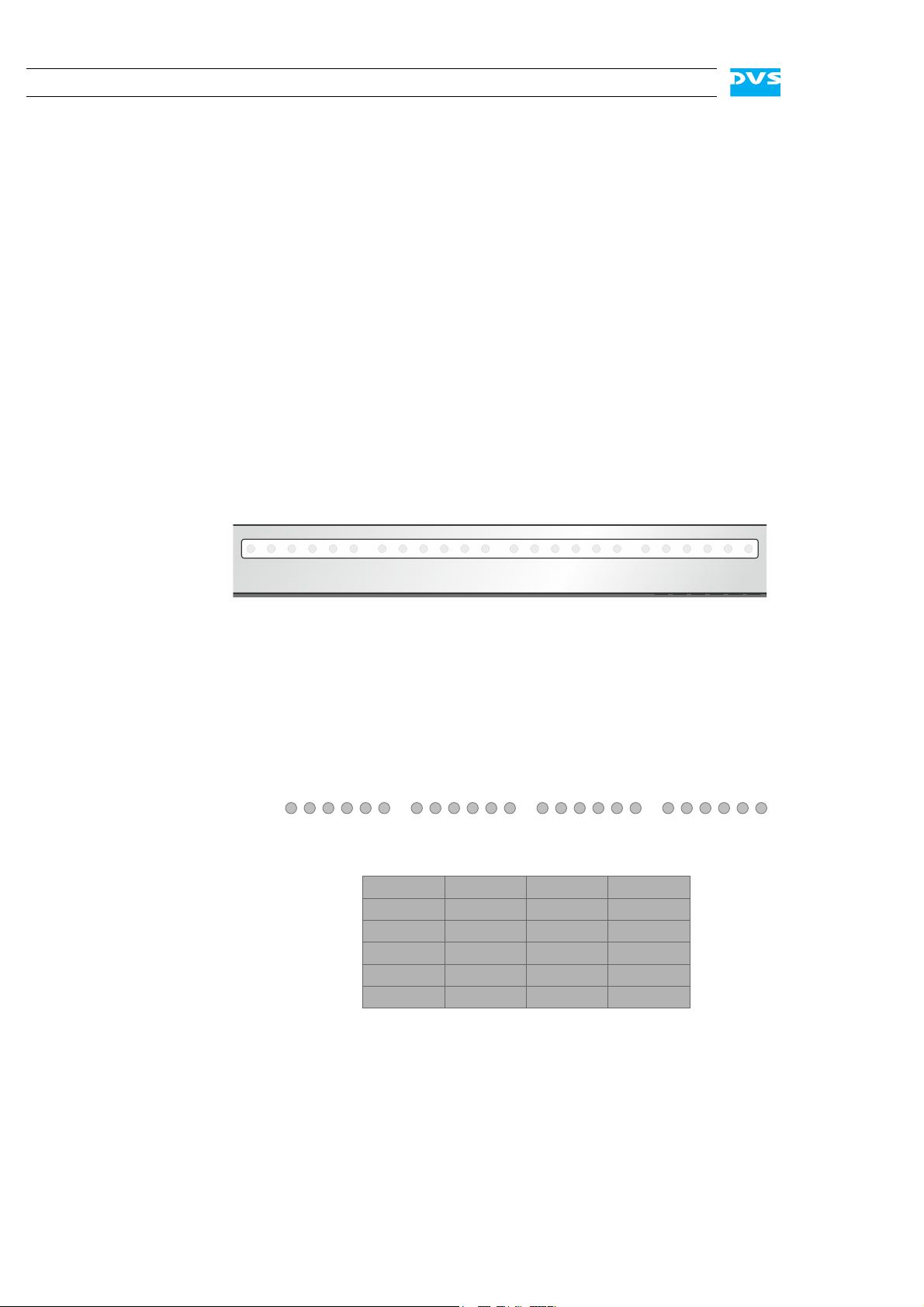
2.2.3 HDD LEDs
The HDD LEDs show the statuses (activities) of the hard disks of the
hard disk array (see section “Hard Disk Array” on page 2-6). They can
be seen only when they are flashing because they are located behind
the white strip and thus not visible when off.
on.
cut from power: Insert a thin, pointed object
into the emergency eject hole. Then the DVD
tray opens.
Figure 2-3: HDD LEDs
SpycerBox Ultra
For the SpycerBox Ultra each LED represents one hard disk of the hard
disk array:
Figure 2-4: HDD LEDs and the hard disk array (SpycerBox Ultra)
Starting from the left, the first six LEDs display the accesses to hard
disks in the very left column of the array, the second six LEDs show the
state of the hard disks of the second column, and so on.
2-4
Page 23
Overview
A
1
BC
234781256783456
23344
LEDs:
hard disks:
5 3 1 7
5
5
8
8
A
86 4 2
667
7
112
2334455
8
8
667
7
112
2334455
8
8
667
7
112
BC
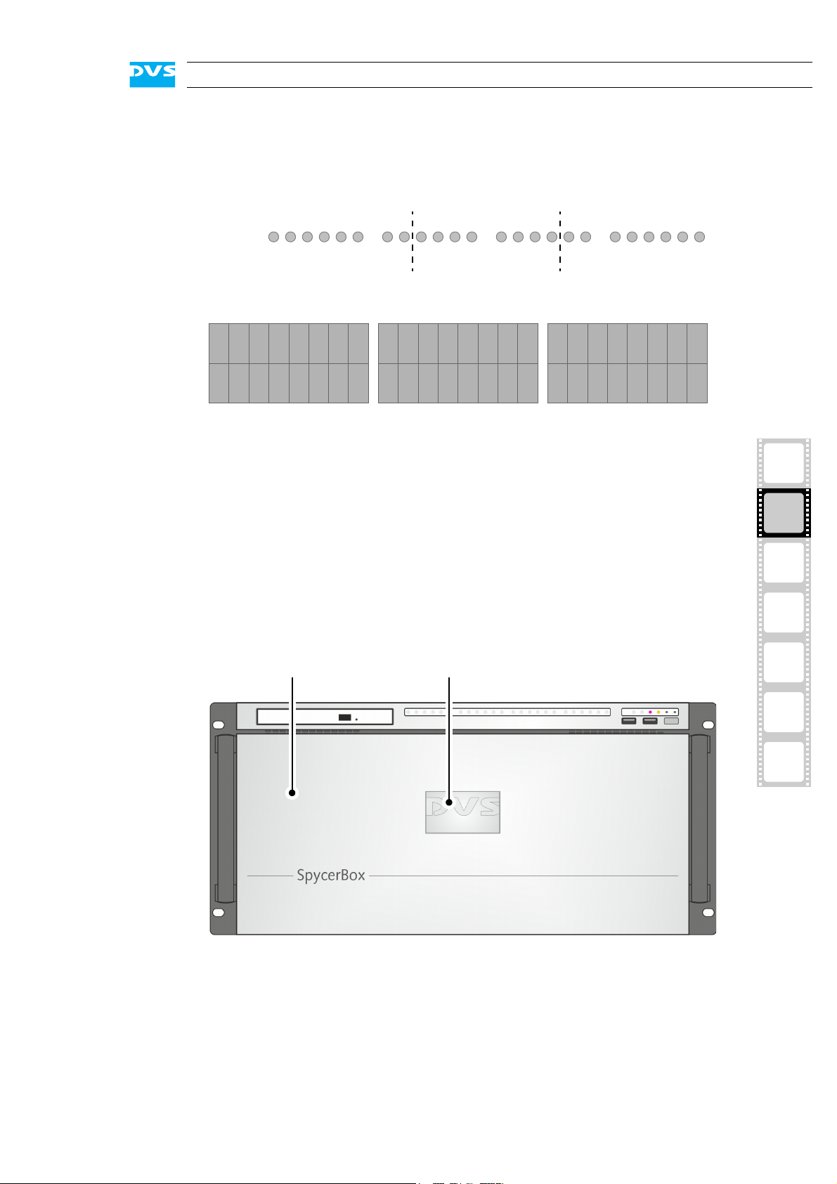
faceplate backlit DVS logo
SpycerBox Flex
For the SpycerBox Flex the state of every two hard disks of the hard
disk array is displayed by one LED.
Figure 2-5: HDD LEDs and the hard disk array (SpycerBox Flex)
Starting from the left, the first eight LEDs display the accesses to the
hard disks in the first eight columns of the hard disk array (16 hard
disks), the second eight LEDs show the state of the second eight columns, and so on.
2.2.4 Faceplate
The faceplate covers the hard disks of the hard disk array.
1
2
3
4
5
A
I
Figure 2-6: Overview of the faceplate
The faceplate is built with an integrated backlit DVS logo which indicates the state of the system, i.e. its power-on status: If the DVS logo
is illuminated, the power is turned on; if not, the power is turned off.
2-5
Page 24

SpycerBox Ultra/Flex Hardware Guide
The top side of the faceplate is hinge-fastened, while its bottom side is
fixed with magnets. If you need access to one of the hard disks, for example, to replace it, you just have to lift the faceplate:
Then you can access the hard disks of the hard disk array (see section
“Hard Disk Array” on page 2-6).
Figure 2-7: Lifting of faceplate
The faceplate can be removed for transport reasons (see section “Removal of the Faceplate” on page 5-20).
2.2.5 Hard Disk Array
The hard disks of the hard disk array are used, for example, to store
proxy clips of your video and audio material or backup files of the connected central storage. It is the main storage of the DVS system. To prevent data loss in case a hard disk fails, it is normally RAID protected.
Further information about RAID can be found in section “Introduction to RAID” on page 5-2.
The system hard disk is not among the hard disks of the hard
disk array. It can be found in the system disk array (see section
“System Disk Array” on page 2-12).
Once the faceplate is lifted (see section “Faceplate” on page 2-5), you
have access to the hard disk array:
2-6
Page 25

Overview
lifted faceplate hard disk array hinge wire
SpycerBox Ultra:
SpycerBox Flex:
1
Figure 2-8: Hard disk array (SpycerBox Ultra and SpycerBox Flex)
The hinge wires hold the faceplate in place and allow you to lift
it. For further information see section “Faceplate” on page 2-5
and section “Removal of the Faceplate” on page 5-20.
Each hard disk of the array is connected to the system with the help of
a disk carrier which makes the removal of a hard disk from the system
easy, for example, in the event of a failure.
2
3
4
5
A
I
2-7
Page 26

SpycerBox Ultra/Flex Hardware Guide
lever openerdisk carrier
LED disk
LED disk
activity
power
SpycerBox Ultra:
lever opener disk carrier
LED disk
LED disk
power
activity
SpycerBox Flex:
Figure 2-9: Hard disk carrier overview (SpycerBox Ultra and SpycerBox Flex)
Further information about how to remove and exchange a hard
disk can be found in section “Hard Disk Maintenance” on
page 5-2.
disk carrier The disk carriers hold each one hard disk of the
array. The hard disks are mounted to the disk
carriers with several screws.
lever Once the lever is unlatched with the opener, it
can be used to pull the disk carrier and its hard
disk out of the system.
opener Unlatches the lever and with it the disk carrier.
LED disk power Shows whether the disk of the disk carrier re-
ceives power.
LED disk activity Indicates the status of the hard disk of the disk
carrier (see also section “HDD LEDs” on
page 2-4):
off Hard disk is idle.
green Hard disk is accessed.
2-8
red A hard disk or hard disk carrier related
error has occurred.
Page 27

2.2.6 Operation Items
1 2 3 4 5 6
7 8 9
With the operation items at the system’s front the hardware of the
SpycerBox can be controlled (e.g. turned on or off). There you can also
find LEDs that allow you to assess the state of the DVS system as well
as USB connectors.
Overview
Figure 2-10: Operation items overview
The LEDs can be seen only when they are flashing because
they are located behind the white strip and thus not visible
when off.
Further information about what to do in case of an alarm can
be found in section “Troubleshooting” on page A-2.
No. Item Explanation
1, 2 LAN 1/2 LEDs Indicate that a valid network is connected to the
first/second LAN connection at the rear of the
system (see section “ATX Connector Panel” on
page 2-13).
3 alarm LED This LED indicates that a hardware malfunction
has occurred.
4 DVD Indicates accesses to the DVD drive.
5 mute In case of a hardware malfunction a system
alarm turns on. By pressing this button the
alarm buzzer can be switched mute. Use a thin,
pointed object to press this button.
1
2
3
4
5
A
I
Some alarms (e.g. the one in case of a
hard disk failure) are independent of
the system alarm and cannot be
switched mute with the mute button.
6 reset Resets your system and initiates a warm re-
boot. Use a thin, pointed object to press this
button.
Save your data before resetting the
system. Otherwise data may be lost.
2-9
Page 28

SpycerBox Ultra/Flex Hardware Guide
No. Item Explanation
7, 8 USB ports The USB connectors (universal serial bus) at the
9 power The power switch turns the system on or off.
front offer you the possibility to connect other
devices such as memory sticks easily.
The respective state of the system will be indicated by the DVS logo in the middle of the faceplate (see section “Faceplate” on page 2-5).
2-10
Page 29

2.3 Overview of the Rear
power supply
system ATX connector slot panel
disk array panel connectors
This section provides an overview of the rear of the system. After an
overall overview of the rear the system disk array will be described, followed by detailed descriptions of the ATX connector panel and the slot
panel connectors. The section will be concluded with further details
about the power supply.
2.3.1 The Rear of the System
This section provides an overview of the rear of the system:
Overview
1
Figure 2-11: Overview of the rear
system disk array The system disk array contains the hard disks
for the operating system and metadata. You
can find further information about this in section “System Disk Array” on page 2-12.
ATX connector panel On this panel you can find the standard con-
nectors of the computer system. Further information about them can be found in section
“ATX Connector Panel” on page 2-13.
2
3
4
5
A
I
power supply The redundant power supply provides the sys-
tem with power. It consists of several independent power supply units: Even if one fails the
others will still supply enough power to keep
the system operational. Further information
about the power supply can be found in section “Power Supply” on page 2-14.
2-11
Page 30

SpycerBox Ultra/Flex Hardware Guide
system disks metadata disks
slot panel connectors The slot panel connectors of the DVS system
2.3.2 System Disk Array
The system disk array contains hard disks for the operating system and
metadata. To prevent data loss in case a hard disk fails, they are normally RAID protected. Furthermore, these hard disks are protected with a
battery backup unit to prevent data loss, for instance, in case of a power
failure.
More information about RAID can be found in section “Introduction to RAID” on page 5-2. The battery backup unit is described in section “Battery Backup Unit” on page 2-17.
provide, for example, the network connections
to connect the system to a SAN. Furthermore,
if applicable, some additional panels may be
present for internal reasons or on customer request. More details about the slot panel connectors can be found in section “Slot Panel
Connectors” on page 2-15.
2-12
Figure 2-12: System disk array
The hard disks of the array are connected to the system with the help
of disk carriers which make the removal of a hard disk easy, for example, in the event of a failure. The system disk array is equipped with the
same type of disk carriers as used in the hard disk array of the SpycerBox Flex (see section “Hard Disk Array” on page 2-6).
Further information about how to remove and exchange a hard
disk can be found in section “Hard Disk Maintenance” on
page 5-2.
Page 31

2.3.3 ATX Connector Panel
1
6
2
8 9 10 13
4 5
1411 12
3
7
The ATX connector panel on the rear of the DVS system holds the connectors of the computer system. It provides the following connections:
Overview
Figure 2-13: ATX connector panel on rear
No. Item Explanation
1 mouse PS/2 connector to connect a mouse to the
system
2 COM port RS-232 connector for the connection of se-
rial interface devices
3 IPMI Dedicated LAN port for IPMI 2.0 (Intelligent
Platform Management Interface) providing
KVM (Keyboard, Video, Mouse redirection)
as well; for further information see the documentation(s) of the original manufacturer(s)
IPMI can be activated by assigning
an IP address to its port via the DVS
Configuration Tool (see section
“DVS Configuration Tool” on
page 4-3). After the assignment
you may have to wait several minutes before the configuration takes
effect.
1
2
3
4
5
A
I
4 CEN/LFE Connector for center out and subwoofer
5 line in Connector to input audio signals
6 keyboard PS/2 connector to connect a keyboard to
speakers
the system
2-13
Page 32

SpycerBox Ultra/Flex Hardware Guide
latch power cable socketLEDhandle
No. Item Explanation
7 VGA DB-15 connector (female) to connect a
8, 9 USB ports These USB connectors (universal serial bus)
10 LAN (1000 Mb) Gigabit Ethernet (1000 Base-T) connection
11 back surround Connector for rear surround speakers
12 side surround Connector for middle surround speakers
monitor; normally with an extra graphics
card installed, this connector will not be operational; however, it can be used in combination with IPMI/KVM for system
management; if you want to use this port,
please contact DVS directly in case of setup
questions
offer you the possibility to connect other
devices to your system
ports to connect the system to a network
13 front Connector to output audio signals (line out),
14 mike Connector to input low-level audio signals
2.3.4 Power Supply
The redundant power supply provides the system with power. It consists of several independent power supply units: Even if one fails the
others will still offer enough power to keep the system working.
The system can be operated with one power supply unit out
of order. However, if another one fails, a continued operation
of the system cannot be guaranteed. Therefore, it is recommended to change a failed power supply unit immediately
(see section “Power Supply Maintenance” on page 5-14).
The following provides an overview of one of the power supply units:
e.g. for front speakers or headphones
2-14
Figure 2-14: Overview of power supply unit
Page 33

Overview
graphics card
GigabitFibre
Channel Ethernet
SAS
handle With the handle of the power supply unit you
can pull the unit out of the power supply once it
is unlocked with the latch.
LED The LED indicates the state of the power supply
unit:
green Operating normally
off Standby mode
off (alarm LED on) Disconnected from power
or malfunction
latch The latch of a power supply unit locks it in the
power supply. With it the unit can be unlocked
and pulled out of the power supply with the help
of the handle.
power cable socket The socket where the power cable has to be
plugged in to provide the system with power.
1
2.3.5 Slot Panel Connectors
The SpycerBox provides on its slot panel connector area several connection possibilities such as the network ports or ports to connect the
system to a SAN. The following figure shows an example configuration
of the slot panel connector area:
2
3
4
5
A
I
Figure 2-15: Example of a slot panel configuration
2-15
Page 34

SpycerBox Ultra/Flex Hardware Guide
The above layout of the slot panel area is just an example. The one at
your system may differ from the figure above: The position of the individual slot panels may vary and/or other panels may be installed, either
for internal reasons or on your request.
To provide connections to most networks there are various interface
possibilities optionally available for the SpycerBox, such as the following:
Gigabit Ethernet Either a 1 Gigabit Ethernet connection with four
Fibre Channel Fibre Channel connection interface with up to
FireWire Two port FireWire interface.
eSata eSata interface
USB Additional USB 2.0 or 3.0 connection interface
The DVS system provides furthermore the following connection possibilities by default:
ports or a 10 or 40 Gigabit Ethernet connection
with up to two ports.
four ports.
graphics card The monitor for the DVS system has to be con-
nected here. For further information about the
graphics card, please refer to the original manufacturer’s documentation included in the delivery of the system.
SAS The SAS (serial attached SCSI) connector is an
external mini-SAS (SFF-8088) connector that
can be used to connect external storages. An
external storage connected to this port can even
be configured to provide RAID protection.
Data transfers on this port may interfere with the real-time capability of the
DVS system. It is recommended to use
it only at times when no real-time performance is required.
2-16
Page 35

2.4 Battery Backup Unit
To prevent data loss especially for the metadata, the hard disks of the
system disk array (see section “System Disk Array” on page 2-12) are
protected by a battery backup unit. If the system’s operation gets interrupted, for example, in case of a power failure, it will provide power to
the cache of the connected RAID controller, so that buffered data will
not get lost. Once the operation of the system is restored, the cached
data will be written to the hard disks.
The battery backup unit is located inside the casing of the DVS system:
Overview
1
Figure 2-16: Location of battery backup unit inside the system
The battery backup unit is a rechargeable battery that will be charged
automatically when the system is turned on.
2
3
4
5
A
I
2-17
Page 36

SpycerBox Ultra/Flex Hardware Guide
2-18
Page 37

Installation
This chapter describes the installation of the SpycerBox. It is divided
into the setup of the system’s hardware and a note about how to connect it to a network.
3.1 System Setup
3
1
This section describes the setup of the SpycerBox hardware. The system must be installed properly before you can start working with it.
To install the hardware of the SpycerBox perform the following:
Unpack the DVS system and its accessories.
Check your delivery and compare it with the delivery note included in the package on an extra sheet of paper. In case of
missing items, please contact your local vendor or DVS immediately.
To make warranty claims you have to keep the original packing and use it in case of a return transportation.
Place the DVS system on a firm, flat surface within reach of a power
outlet or mount it in a rack. For good air circulation and cooling
make sure the ventilation holes are not covered.
Connect at least the following computer peripherals:
–Mouse,
– keyboard and
– a monitor that is operable at a resolution of at least
1280 × 1024 pixels (default manufacturing setting).
2
3
4
5
A
I
Connect any other peripheral computer equipment. For an overview
of the panels and connectors at the system’s rear see section
“Overview of the Rear” on page 2-11.
Connect the power cable(s) to the system.
3-1
Page 38

SpycerBox Ultra/Flex Hardware Guide
The SpycerBox hardware is now properly installed and you can switch
on the system as described in section “Starting the System” on
page 4-2.
3.2 Note about the Network Installation
Because of the amount of possible workflows that customer’s may use
the SpycerBox for as well as network connections (see section “Slot
Panel Connectors” on page 2-15), this document does not describe
how to connect the DVS system to a network or central storage. On the
DVS web page (www.dvs.de) you can find some diagrams showing
how the SpycerBox may fit in a workflow/network.
To connect the DVS system to a network/central storage you should
have experience as a network administrator and know how to set up
the required network connections on the installation site in hard- as
well as software. In case you experience difficulties during the installation, DVS offers you special assistance that will be tailored to your personal needs and which can range from remote diagnosis to on-site
services. Please contact the DVS service department for further information about this.
3-2
Page 39

Operation
power switch
This chapter describes how to operate the SpycerBox hardware, i.e. it
is explained how to start the system and how to shut it down. For both
procedures you have to use the power switch of the operation items at
the front of the system.
Additionally, the DVS Configuration Tool is described briefly which allows you to configure, reboot and shut down the SpycerBox.
4
Figure 4-1: The power switch
All other items necessary for a correct operation of the SpycerBox hardware, such as the LEDs or the buttons, are described
in chapter “Overview” on page 2-1.
1
2
3
4
5
A
I
4-1
Page 40

SpycerBox Ultra/Flex Hardware Guide
4.1 Starting the System
After a proper installation of the system (see chapter “Installation” on
page 3-1) you may start the DVS system at any time.
To start the system perform the following:
Press the power switch briefly to turn on the system.
The system will be started and the DVS logo in the middle of the faceplate lights up. As with any standard computer after initial booting, the
system begins to load the installed operating system.
During the start-up of the system several alarm beeps will be
sounded. This is part of a self-test and does not indicate an error or malfunction.
When the operating system has finished its loading, you can begin to
work with the DVS system right away.
4-2
Page 41

4.2 DVS Configuration Tool
The DVS Configuration Tool can be used to configure, reboot and shut
down the SpycerBox. Once the operating system is loaded, it can be
found on the desktop of the SpycerBox.
The DVS Configuration Tool will run in the standard web browser of
your system. The address is either localhost (127.0.0.1) or the IP
address of the SpycerBox in the network. After starting it you have to
enter a user name (default: admin) and password (default: dvssan).
Operation
1
Figure 4-2: Starting screen of the DVS Configuration Tool
With the DVS Configuration Tool you can change the configurations of
the DVS system (e.g. its IP address or Fibre Channel connections). Click
on the respective item to the left to view and change the configurations. Afterwards you will see the options that can be changed.
The DVS Configuration Tool can also be used to gather log files of the
system, for example, for troubleshooting. By default they will be saved
in a single archive file on the desktop of your system.
Additionally, with the DVS Configuration Tool you can reboot or shut
down the DVS system.
2
3
4
5
A
I
4-3
Page 42

SpycerBox Ultra/Flex Hardware Guide
4.3 Shutting Down the System
There are several possibilities to shut down the DVS system. All depend
on whether the operating system is already loaded, frozen or not completely loaded. Please act accordingly.
To shut down the system perform the following according to the state
of the system’s operating system:
After a shut-down wait at least ten seconds before starting the
system again. This time is needed to safely erase all memory
banks of the system.
With the operating system fully loaded
If the operating system is up and running, there are two ways to shut
down your system:
1. Turn the system off by shutting down the operating system the
usual way (see also section “DVS Configuration Tool” on
page 4-3).
The operating system will then save your personal settings and once it
has ended, the system will turn off.
2. Alternatively, you can initiate a fast shut down by pressing the
power switch briefly.
The fast shut down may not save all your system data and
personal settings before the system turns off.
Some settings will be saved and afterwards the system turns off.
With the operating system frozen or not completely loaded
If the operating system is not responding anymore or not completely
loaded, perform the following:
This procedure can cause corrupted system data. However, the
system should be sufficiently protected against this by the
journaling file system and the battery backup unit (see section
“Battery Backup Unit” on page 2-17).
Shut down the system by pressing the power switch until the sys-
tem turns off.
The system will then shut down immediately.
4-4
Page 43

Maintenance
This chapter explains the maintenance work that you can perform on
your own. For each work a detailed procedure description is given. If
you experience trouble with the system that cannot be resolved with
the work described here or in section “Troubleshooting” on page A-2,
please contact your local vendor or DVS directly.
5
1
2
3
4
5
A
I
5-1
Page 44

SpycerBox Ultra/Flex Hardware Guide
5.1 Hard Disk Maintenance
This section deals with the possible event of a hard disk failure. First,
some introductory information about RAID are provided. After that follow descriptions how to act when a hard disk fails.
5.1.1 Introduction to RAID
In a system where huge amounts of data are processed, large storage
capacities combined with high data throughputs are mandatory. To
provide both at the same time it is common practice in the area of video
and digital film to configure several hard disks together into a stripe set
or RAID. The IT world has defined several ’levels’ of RAID, most of them
providing some kind of data protection.
The RAID feature makes the DVS system tolerant of disk failures. Even
with a broken disk operations can still be continued and, once the failed
disk has been replaced, the missing data can be recovered easily. The
data protection is provided by RAID controllers installed inside the system. Each controller independently administers the data protection for
the set of hard disks that is connected to it.
The system disk array for the system/metadata hard disks comprises
four disks. They are connected to a RAID controller that applies a
RAID 1 to the data, meaning that they are protected by a mirroring of
the data between two disks. If one of the hard disks fails, the missing
data can be restored with the mirrored information stored on the other
disk.
If the second disk fails in the meantime, the data will be unrecoverable.
The main storage of the DVS system comprises up to 24 hard disks
(SpycerBox Ultra; SpycerBox Flex: 48 hard disks). These are connected
to three RAID controllers which connect a set of eight hard disks each
(SpycerBox Ultra; SpycerBox Flex: 16) and apply a RAID 5 to the data.
With this, the data is striped across these hard disks during write procedures. At the same time the information necessary to rebuild a failed
hard disk (parity information) is generated and written across the disks
as well. With the parity information written, one hard disk per disk set
(RAID pack) can fail and your data will still be recoverable due to the
information stored on the other disks.
If a second disk within the same disk set fails in the meantime,
the data will be unrecoverable.
5-2
You can identify the hard disks that are connected to a RAID controller
easily at the DVS system because every three rows (SpycerBox Ultra;
SpycerBox Flex: every column of 16 hard disks) represent one disk set/
RAID pack:
Page 45

Maintenance
disk set 1
disk set 2
d
isk
se
t
3
SpycerBox Ultra:
SpycerBox Flex:
disk set 1 disk set 3disk set 2
1
2
3
4
5
A
Figure 5-1: Disk sets (RAID packs) of the hard disk array (SpycerBox Ultra and Flex)
I
With the available RAID feature the DVS system can withstand disk failures without losing data or access to data.
5-3
Page 46

SpycerBox Ultra/Flex Hardware Guide
5.1.2 Identifying a Broken Hard Disk
In case of an alarm or when suspecting a worn hard disk, you have to
identify the broken hard disk first in order to replace it.
An alarm can be caused by a number of reasons. Please refer
to section “Troubleshooting” on page A-2 first for further details about what to do in case of an alarm.
If a hard disk fails, the alarm will be sounded by a RAID controller. It cannot be switched mute with the mute button of the
operation items. It can be turned off either with the RAID software manager or by replacing the broken hard disk.
Data accesses to the hard disk array are still possible because
any missing data will be recalculated from the parity information stored on the other hard disk(s). This can limit the overall
performance and real-time operations may no longer be possible.
Replace the failed disk as soon as possible. If you do not replace a broken disk in time and another disk fails in the meantime, your data may be unrecoverable.
Before replacing a hard disk you have to gather the log files of
the RAID controller. If you know how to do this you may proceed on your own. If not, please contact the DVS service department first.
In most cases you can find the broken disk by simply observing the
LEDs of the disk array (see section “Hard Disk Array” on page 2-6 and
section “System Disk Array” on page 2-12). While performing continuous accesses to the data, it will be the one:
– no longer blinking (either continuously on or off),
– irregularly blinking compared to the other hard disks of the
same disk set, or
– showing a hard disk or disk carrier related error (see section
“Hard Disk Array” on page 2-6 and section “System Disk
Array” on page 2-12).
Once the broken disk has been identified, you can replace it as described in section “Replacing a Hard Disk” on page 5-5.
Replacing the wrong hard disk, i.e. a good one instead of the
broken one, may result in a total loss of data.
If you are unsure about having detected the correct hard disk
please contact the DVS service department.
5-4
Page 47

5.1.3 Replacing a Hard Disk
SpycerBox Ultra:
As soon as the broken hard disk has been identified (see section “Identifying a Broken Hard Disk” on page 5-4), it can be replaced easily. The
replacement of a broken hard disk can be divided into three steps:
1. Removing the hard disk from the system.
2. Replacing the hard disk.
3. Reassembling it into the system.
All steps are explained in the following.
Before replacing a hard disk you have to gather the log files of
the RAID controller. If you know how to do this you may proceed on your own. If not, please contact the DVS service department first.
Step 1: Removing the Hard Disk
Maintenance
The hard disks that are accessible at the front and rear of the system
are connected to the system with the help of disk carriers. They can be
removed easily, even when the system is running (hot-swappable).
For an overview of a disk carrier as well as further information
about it see section “Hard Disk Array” on page 2-6 and section
“System Disk Array” on page 2-12.
To remove a hard disk from the system perform the following:
If appropriate, stop all accesses to the hard disks of your system,
for example, by exiting software and severing the network connections.
Lift the faceplate of the system (see section “Faceplate” on
page 2-5).
Then, unlatch the disk carrier of the defective hard disk by pressing
the opener of the disk carrier (1).
This will cause the lever to come out of the disk carrier so that it protrudes from the rest of the disk carriers.
Take the lever and turn it in its hinge (2) until it cannot be moved
further:
1
2
3
4
5
A
I
5-5
Page 48

SpycerBox Ultra/Flex Hardware Guide
SpycerBox Flex and system disk array:
This takes the hard disk installed in the disk carrier out of the system’s
interfaces inside.
Once the interface connections inside the system are severed, you
can pull the disk carrier out of the system.
Now the hard disk is removed from the system and it has to be replaced
in the next step.
Step 2: Replacing the Hard Disk
Figure 5-2: Pulling out the lever
To replace the hard disk do the following:
Significant environmental changes, for example, altitude,
voltage, temperature, shock, vibration, etc., can damage a
hard disk. Therefore, handle hard disks with great care.
Unscrew the screws that fix the hard disk to the disk carrier.
Exchange the broken disk with a new one and assemble it in the
disk carrier with the screws.
It is best to use the same brand and type of hard disk again.
Otherwise a loss of performance might occur.
After that the hard disk is replaced and the disk carrier with the new
disk has to be reassembled in the system.
Step 3: Reassembling the Hard Disk
After replacing the hard disk, the disk carrier with the new disk has to
be reassembled in the system. For this perform the following:
Slide the disk carrier back into its shaft at the disk array.
Push the disk carrier completely back into the shaft by applying
pressure to the disk carrier directly (i.e. do not use the lever to push
the carrier). Move it until you feel the resistance of the hard disk
interface inside the system and until the lever retracts by itself from
the pushing.
It is important that you do not use the lever to insert the
disk carrier. Apply an even pressure only to the carrier directly until the lever moves back by itself.
5-6
Page 49

Maintenance
Then simply close the lever until it snaps back in place which as a
result will slide the carrier completely back in.
The disk carrier of the replaced disk should be level with the
others of the array.
Once the faceplate of the DVS system is back in place, the replacement
of t he hard disk is finished . After several minutes the replaced hard disk
will be automatically recognized by the system. Then the rebuild of the
data will be initiated on its own. When the system has finished the rebuild, the DVS system will be fully operational again.
During a rebuild real-time processes may not be possible. It is
recommended to restrict accesses to the hard disk array until
the rebuild is finished.
A rebuild takes several hours. It is strongly recommended to
avoid accesses to the disk array during this time, otherwise it
may take considerably longer.
1
2
3
4
5
A
I
5-7
Page 50

SpycerBox Ultra/Flex Hardware Guide
5.2 Opening and Closing the Casing
Some tasks described in this manual require an opening of the system’s casing and the closing of it afterwards once the intended work is
finished. Both tasks will be explained in this section.
5.2.1 Opening the Casing
To open the casing of the DVS system perform the following:
The system you are working on operates with voltages
that can be hazardous to your health. Never work on the
system or access its interior with the power cable(s) being
plugged in. Make sure the power supply is disconnected
from the components you intend to work on.
The system must be operated only with the chassis’ cover installed to ensure proper cooling.
Shut down the system as described in section “Shutting Down the
System” on page 4-4.
Disconnect all power cords from the system.
Press the two buttons at the top of the system (1) and move the
cover towards the rear of the system (2).
Figure 5-3: Removal of the cover of the casing
Once the cover is slid backward, it can be taken off the system.
5.2.2 Closing the Casing
After finishing your task at hand you have to close the casing of the
DVS system again. For this perform the following:
Simply put the cover back on and slide it into place until it locks.
Afterwards reconnect the power cords.
5-8
Page 51

With this the task of closing the casing is finished and you can turn the
system back on at any time.
5.3 Fan Maintenance
To cool the many hard disks installed in the system as well as the other
electronic parts (e.g. the motherboard), the system is equipped with
several fans that can be exchanged in case of a failure easily. This section describes what to do if a fan failure takes place.
When a fan failure occurs, you will be notified by a lit alarm LED and
the sounding of an alarm buzzer of the system. The alarm can be
switched mute with the mute button at the front of the system (see section “Operation Items” on page 2-9). Then you have to do the following
to exchange the failed fan:
Maintenance
An alarm can be caused by a number of reasons. Please refer
to section “Troubleshooting” on page A-2 first for further details about what to do in case of an alarm.
The system you are working on operates with voltages
that can be hazardous to your health. Never work on the
system or access its interior with the power cable(s) being
plugged in. Make sure the power supply is disconnected
from the components you intend to work on.
Maintenance inside the system should only be performed
by personnel qualified for handling and testing electrical
equipment.
Computer hardware contains components that are sensitive
to electrostatic discharge. If you touch them without precautionary measures, they can be destroyed. Use a wrist strap
connected to ground when accessing electronic parts and
take care of grounding the system. Avoid touching the internal components of the computer system.
Open the casing of the system as described in section “Opening the
Casing” on page 5-8.
With the casing of the system open, you can now test the fans. For this
you have to plug in the power supply again.
1
2
3
4
5
A
I
Testing the fans is possible only with an opened casing
and the power turned back on.
Once the power cables are plugged in again do not touch
anything else than the external power cords or the power
switch at the front of the system. Under no circumstances
reach inside the system.
After testing the fans switch off the power and disconnect
the power cables immediately.
5-9
Page 52

SpycerBox Ultra/Flex Hardware Guide
Reconnect the power cords.
Press the power switch to turn on the system.
Observe the fans and memorize the failed one (the fan not revolving
is the broken one).
Press the power switch until the system turns off.
After this disconnect the power cables once again.
With the broken fan identified you can replace it. For this perform the
following:
Press the latch of the respective fan module towards the front of
the system (1).
With the locking mechanism released pull the fan module up and
out of the system (2).
5-10
Figure 5-4: Removal of fan module
This will sever the connection of the fan to the system.
Unscrew the finger protection grille from the broken fan and after-
wards screw off the fan from the fan bracket.
Replace the broken fan with a new one and reassemble the fan
module: Screw the fan to the fan bracket and afterwards the finger
protection grille to the fan.
Only use original manufacturer spare parts. Other spare
parts might damage your system.
Page 53

Maintenance
Re-insert the repaired fan module into the system.
See to it that the fan module plugs properly into the system’s fan interface and that, when completely inserted, the
locking mechanism snaps back into its locked position.
Next close the casing of the system as described in section “Clos-
ing the Casing” on page 5-8.
With the last step finished you have successfully replaced the defective
fan module. Once the system is turned on, no alarm should be sounded
anymore.
1
2
3
4
5
A
I
5-11
Page 54

SpycerBox Ultra/Flex Hardware Guide
5.4 Controller Maintenance
During the service life of the DVS system you may have to exchange a
RAID controller (see section “Introduction to RAID” on page 5-2). It
may be indicated, for example, if a disk set (RAID pack) cannot be accessed anymore. This section describes how to exchange a RAID controller.
Before exchanging a RAID controller contact the DVS service
department.
The system you are working on operates with voltages
that can be hazardous to your health. Never work on the
system or access its interior with the power cable(s) being
plugged in. Make sure the power supply is disconnected
from the components you intend to work on.
Maintenance inside the system should only be performed
by personnel qualified for handling and testing electrical
equipment.
Computer hardware contains components that are sensitive
to electrostatic discharge. If you touch them without precautionary measures, they can be destroyed. Use a wrist strap
connected to ground when accessing electronic parts and
take care of grounding the system. Avoid touching the internal components of the computer system.
Identify the controller or disk set that causes the problem, for exam-
ple, by consulting either the RAID software manager or the BIOS of
the RAID (press [Ctrl + H] at the indicated moment during start-up
of the system).
Then, open the casing of the system as described in section “Open-
ing the Casing” on page 5-8.
On the defective controller memorize the order of the cables that
are connected to it. To make this easy the cables are numbered.
Disconnect the cables connected to the controller.
Remove the defective controller from the system and in its place
install a new one.
Only use original manufacturer spare parts. Other spare
parts might damage your system.
5-12
The new controller must have the same firmware installed
as the other controllers.
Connect the cables to the controller again in the same manner as
they were on the old controller.
Next close the casing of the system as described in section “Clos-
ing the Casing” on page 5-8.
Page 55

Maintenance
With the last step finished you have successfully replaced the defective
RAID controller. Now, you have to integrate the new controller in the existing configuration:
Turn on the system as described in section “Starting the System”
on page 4-2.
After the initial booting you will see something like the following on the
screen:
Foreign configuration(s) found on adapter:
Press any key to continue or ’C’ to load the
configuration utility,
or ’F’ to import foreign configuration(s) and continue
Press [F] on the keyboard to accept the configuration detected by
the system.
After this the newly installed RAID controller automatically initiates a
verify of the connected hard disks which may take some time. When
finished, the system will continue its booting procedure until the operating system is fully loaded. You may then continue your work with the
system.
In some cases the boot device cannot be found after accepting
a configuration. Then you have to specify the boot device in the
BIOS of the RAID. To access the RAID BIOS press [Ctrl + H] at
the indicated moment during the start-up of the system. The
setting can be found after selecting the respective controller
and switching to ’Virtual Drives’.
1
2
3
4
5
A
I
5-13
Page 56

SpycerBox Ultra/Flex Hardware Guide
5.5 Power Supply Maintenance
The redundant power supply provides the system with power. It is a reliable and enduring part of the system because it consists of several independent power supply units: Even if one fails the others will still offer
enough power to keep the system working.
The system can be operated with one power supply unit out
of order. However, if another one fails, a continued operation
of the system cannot be guaranteed. Therefore, it is recommended to change a failed power supply unit immediately.
When a power supply unit failure occurs, you will be notified by a lit
alarm LED and the sounding of an alarm buzzer of the system. The
alarm can be switched mute with the mute button at the front of the
system (see section “Operation Items” on page 2-9).
An alarm can be caused by a number of reasons. Please refer
to section “Troubleshooting” on page A-2 first for further details about what to do in case of an alarm.
Each power supply unit in the DVS system is hot-swappable, so you
can safely replace it with the system running. Follow these steps to replace a power supply unit:
For an overview of a power supply unit see section “Power
Supply” on page 2-14.
Take a look at the power supply at the rear of the system and exam-
ine the LEDs of the units. The LED of the malfunctioning power
supply unit should be extinguished.
Next unplug the power cord from this power supply unit.
Unscrew the security screw of the latch.
Take the handle of the respective unit and press the unit’s latch to
the left to unlock it.
Then pull the unit at its handle out of the power supply.
Do not reach inside the system when removing a power
supply unit or when the unit is out of the system.
Change the power supply unit against a new and operable one.
5-14
Slide the new unit into the power supply until it clicks into place.
Only use original manufacturer spare parts. Other spare
parts might damage your system.
When completely inserted please observe that the latch is
truly in place and locking the unit.
Page 57

Maintenance
Tighten the security screw of the latch again.
Connect the power source (power cord) to the newly installed
power supply unit.
After that check the LED indicating the status of the power supply
unit: If it is lit up in green, the unit is working properly.
With this the power supply unit has been replaced successfully.
1
2
3
4
5
A
I
5-15
Page 58

SpycerBox Ultra/Flex Hardware Guide
5.6 Backup or Recovery of the System Disk
The DVS system provides internally a USB flash drive that can be used
to back up or restore the operating system on the system hard disk.
With it you can, for example, set the system disk back to its manufacturing state. Once selected as a boot device, it will launch a Live Linux
which in turn will either back up or restore the system hard disk. The
following sections describe how to create a backup image or perform
a recovery of the system disk.
5.6.1 Creating a Backup Image of the System Disk
The following describes the steps to make a backup image of the system hard disk and save it to the internal USB flash drive:
Do not execute any commands if you are not sure about the
correct source and target device. For example, selecting the
wrong source device could lead to a full storage space and a
termination of the process.
To complete the loading of the DVS Rescue environment some
user entries are required. For this follow the instructions given
on the screen.
The loading of the environment and the process itself will both
try to initialize hardware that may not be present on your system. Any error messages displayed during loading/initialization, e.g. Failed or Warning, can be disregarded. The
backup/recovery process should work nonetheless.
The storage space on the USB is limited. The number of backup images that can be stored on the drive, besides the DVS recovery image ex factory available, depends on the size of the
image files. If the process fails, the storage drive may be full.
However, an already created image can be overwritten when
assigning the same name to it.
If appropriate, disconnect all Fibre Channel cables and all externally
connected storage devices from the system.
Turn on or restart the DVS system and at the indicated moment dur-
ing start-up press [F11] on your keyboard to enter the boot menu.
Once the boot menu is displayed on the screen, select the internally
installed USB flash drive as the boot device and then press [Enter]
on your keyboard.
5-16
With this the target device has been selected. The system will now boot
from the internal USB and you will see a window on the screen where
you can select the DVS Rescue environment for loading:
Select DVS Rescue and press [Enter] on your keyboard.
Page 59

Maintenance
Once the loading has finished, you will see the DVS Rescue script with
its options on the screen. Your display should look similar to the following:
--- DVS Rescue ---
1 - Backup on internal USB device
2 - Restore from internal USB device
3 - Reboot the system
4 - Poweroff the system
0 - Exit
Enter selection:
To make a backup image of your system disk and save it to the
internal USB, press [1] and then [Enter] on your keyboard.
Afterwards a list of possible source devices will be detailed on the
screen. In a SpycerBox the system drive normally will be ’sdc’, but on
special systems it may also be ’sda’, ’sdb’, etc.
1
Ex factory the DVS system will be delivered with ’sdc’ as the
default system disk. If other configurations have been made
later or on customer request, this may be different.
Continue with the following steps only, when you are able to
identify the correct source device.
Enter the name of the system disk: Type in sdc (or in other cases
sda, sdb, etc.) and press [Enter] on your keyboard.
The system will now ask you to enter the image name for your backup
image to be saved. By entering the name of an already existing backup
image you can overwrite it.
Type in the name of the image you want to save to the USB and
press [Enter] on your keyboard.
The system will ask you to confirm your selection and whether you
want to continue:
To start the backup process type in y for ’yes’ and press [Enter] on
your keyboard.
To abort the process at this point enter n for ’no’ and press
[Enter] on your keyboard. You will be redirected to the DVS
Rescue script.
2
3
4
5
A
I
After starting the process a termination is not possible anymore.
5-17
Page 60

SpycerBox Ultra/Flex Hardware Guide
The program will now start the backup process. Its progress will be indicated on the screen.
The backup process may take some time.
If during the process the screen turns black, press [Space] to
get it back again.
When the system has finished the backup process, you will be notified
about this. Then after pressing [Enter] on your keyboard, you will be redirected to the DVS Rescue script once more where you can choose,
for example, ’reboot’ or ’poweroff’ to restart or turn off the system.
5.6.2 Restoring the System Disk
The following describes the steps to make a recovery of the system
hard disk:
Do not execute any commands if you are not sure about the
correct source and target device. For example, selecting the
wrong target device can lead to a total loss of data.
To complete the loading of the DVS Rescue environment some
user entries are required. For this follow the instructions given
on the screen.
The loading of the environment and the process itself will both
try to initialize hardware that may not be present on your system. Any error messages displayed during loading/initialization, e.g. Failed or Warning, can be disregarded. The
backup/recovery process should work nonetheless.
If appropriate, disconnect all Fibre Channel cables and all externally
connected storage devices from the system.
Turn on or restart the DVS system and at the indicated moment dur-
ing start-up press [F11] on your keyboard to enter the boot menu.
Once the boot menu is displayed on the screen, select the internally
installed USB flash drive as the boot device and then press [Enter]
on your keyboard.
The system will now boot from the internal USB and you will see a window on the screen where you can select the DVS Rescue environment
for loading:
Select DVS Rescue and press [Enter] on your keyboard.
5-18
Once the loading has finished, you will see the DVS Rescue script with
its options on the screen. Your display should look similar to the following:
--- DVS Rescue ---
1 - Backup on internal USB device
2 - Restore from internal USB device
Page 61

Maintenance
3 - Reboot the system
4 - Poweroff the system
0 - Exit
Enter selection:
To restore your system disk from the internal USB, press [2] and
then [Enter] on your keyboard.
Afterwards a list of possible target devices will be detailed on the
screen. In a SpycerBox the system drive normally will be ’sdc’, but on
special systems it may also be ’sda’, ’sdb’, etc.
Ex factory the DVS system will be delivered with ’sdc’ as the
default system disk. If other configurations have been made
later or on customer request, this may be different.
Continue with the following steps only, when you are able to
identify the correct target device.
A recovery will overwrite all your data.
1
Enter the name of the system disk: Type in sdc (or in other cases
sda, sdb, etc.) and press [Enter] on your keyboard.
Another list will be displayed on the screen detailing the possible
source images. If there is only the DVS recovery image on the USB
flash drive, this one will be listed. If there are several images, all will be
displayed.
Select the image you want to use for the recovery. Normally, it pro-
vides the serial number of the DVS system in its name. To confirm
your choice press [Enter] on your keyboard.
The system will ask you to confirm your selection and whether you
want to continue:
To start the recovery process type in y for ’yes’ and press [Enter] on
your keyboard.
To abort the process at this point enter n for ’no’ and press
[Enter] on your keyboard. You will be redirected to the DVS
Rescue script.
After starting the process a termination is not possible anymore.
The program will now start the recovery process. Its progress will be indicated on the screen.
2
3
4
5
A
I
The recovery process may take some time.
If during the process the screen turns black, press [Space] to
get it back again.
When the system has finished the recovery process, you will be notified
about this. Then after pressing [Enter] on your keyboard, you will be redirected to the DVS Rescue script once more where you can choose,
5-19
Page 62

SpycerBox Ultra/Flex Hardware Guide
hinge wire
1 22
for example, ’reboot’ or ’poweroff’ to restart or turn off the system. The
next time the DVS system is started, it will load the restored operating
system.
5.7 Removal of the Faceplate
The faceplate of the system can be removed, for example, for transports. For this perform the following:
The system must be operated only with the faceplate installed
to ensure electromagnetic compatibility.
Lift the faceplate of the system (see section “Faceplate” on
page 2-5).
Beneath it you will see a cable with a jack connection that supplies the
DVS logo of the faceplate with power.
Unplug the jack connection.
Next hold tight the faceplate and remove the hinge wires as indi-
cated in the following figure:
Figure 5-5: Removing the hinge wires
5-20
Afterwards the faceplate can be taken off.
To reassemble the faceplate reverse the above steps.
Page 63

Appendix
This chapter first gives some hints how to resolve irregularities during
operation. After that technical data and general information about the
DVS system are provided.
A
1
2
3
4
5
A
I
A-1
Page 64

SpycerBox Ultra/Flex Hardware Guide
A.1 Troubleshooting
The table below lists some errors that may occur during the operation
of the DVS system and details how to resolve them. If you experience
trouble that cannot be resolved with the solutions described here or in
chapter “Maintenance” on page 5-1, please contact your local vendor
or DVS directly.
Error Cause Solution
Accesses to the main
storage are slow.
An alarm is sounded
and the alarm LED is
lit. The alarm can be
switched mute with
the mute button.
The data storage is
too full.
One or more hard
disks of the hard disk
array are worn.
Configurations of the
system or its network
ports have been altered.
A RAID controller is
defective.
One of the power
supply units has been
disconnected from
power during operation.
One of the power
supply units has
failed.
It is recommended to use only 85 to
90% of the overall hard disk capacity.
If the storage is too full, delete some
of your data.
Try to identify the worn disk and replace it as described in section “Hard
Disk Maintenance” on page 5-2.
Contact your local system and network administrator and try to reconfigure the network connections of
the system. If this is not successful
contact the DVS service department.
If you can rule out the above mentioned causes, a RAID controller may
be defective. Before attempting to
exchange a RAID controller (see section “Controller Maintenance” on
page 5-12) contact the DVS service
department.
Check the LEDs of the power supply
units. If one is extinguished, this unit
may be disconnected from power.
Examine the power cord of the unit.
See to it that it is in good technical
order, correctly plugged in at both
ends and that the mains current is
operating properly.
Check the LEDs of the power supply
units. If one is extinguished and you
can rule out the above mentioned
cause, a power supply unit has
failed. Replace the broken unit as described in section “Power Supply
Maintenance” on page 5-14.
A-2
Page 65

Error Cause Solution
An alarm is sounded
and the alarm LED is
off. The alarm cannot
be switched mute
with the mute button.
OR
At start-up the system is not able to initialize a disk set.
Appendix
A fan has failed. Check the LEDs of the power supply
units. If all are green, shut down the
system (see section “Shutting Down
the System” on page 4-4) and check
whether a fan has failed (see section
“Fan Maintenance” on page 5-9). If
necessary replace the broken module as described in the same section.
The system is overheated.
A hard disk or a hard
disk carrier got loose/
jammed (e.g. after
transport) or is not
mounted correctly.
A hard disk of the
hard disk array is defective.
A RAID controller is
defective.
If you can rule out the above mentioned causes, the alarm must be
due to overheating. See to it that the
ambient temperature at the front of
the system does not exceed the operating temperature specified in section “Technical Data” on page A-4. If
the temperature is within the range,
check the ventilation holes of the
system and free them from all obstructions (e.g. dust). In case the
problem persists, contact the DVS
service department.
Shut down the system as described
in section “Shutting Down the System” on page 4-4. Then perform the
following: Pull all disk carriers partially out of the chassis and afterwards
install them again. See to it that they
are pulled out and reassembled correctly as described in section “Replacing a Hard Disk” on page 5-5.
After that start the system again.
Replace the defective disk as explained in section “Hard Disk Maintenance” on page 5-2.
If you can rule out the above mentioned causes, a RAID controller may
be defective. Before attempting to
exchange a RAID controller (see section “Controller Maintenance” on
page 5-12) contact the DVS service
department.
1
2
3
4
5
A
I
A-3
Page 66

SpycerBox Ultra/Flex Hardware Guide
A.2 Technical Data
This section provides technical data of the SpycerBox.
When installing the DVS system in a rack, take care that
warmed up air is conducted to the rear of the rack and properly
vented away.
A.2.1 General Technical Data
The general technical data of the SpycerBox are as follows:
Weight approx. 70 kg
Environment (also
during transport)
Operating
temperature
Storage temperature
Humidity 10 - 80 %, non-condensing at all times
Air Dust-free
Power consumption max. 2500 W (primary)
AC power 100 - 120 VAC, 220 - 240 VAC
No exposure to heat
No exposure to strong electric or magnetic
fields
No vibrations/shocks allowed
Maximum: 10 - 30 °C (50 - 86 °F)
Optimum: 15 - 25 °C (59 - 77 °F)
0 - 50 °C (32 - 122 °F)
nominal 1400 W (primary)
A-4
Page 67

A.2.2 Dimensions
The following figure shows the dimensions of the DVS system. The
drawing already includes some space for connectors and plugs that
can protrude from the rear (’plug safety’ (l minus j), usually plus
150 mm). However, this amount of space depends on the type of connectors used.
Appendix
1
Figure A-1: Measured dimensions
SpycerBox Ultra:
a 220 mm g 197 mm
b 199 mm h 50 mm
c 21 mm i 55 mm
d 25 mm j 697 mm
e 455 mm k 729 mm
f 480 mm l 847 mm
SpycerBox Flex:
a 220 mm g 197 mm
b 199 mm h 50 mm
c 21 mm i 55 mm
d 25 mm j 630 mm
e 455 mm k 662 mm
2
3
4
5
A
I
f 480 mm l 780 mm
A-5
Page 68

SpycerBox Ultra/Flex Hardware Guide
A.3 Packing Instructions
The following describes the best way to pack a DVS system.
Keep the original packing and use it in case of transportation.
Otherwise the warranty will be void.
In any other case, if you do not have the original packing anymore, use a similar structured packing for transportation. DVS
cannot be held liable for damages due to transportation.
Fragile. Avoid shocks or vibrations. For longer distances use a
lifting truck.
Keep dry.
Figure 1:
Wrap video system in foil:
Figure 2:
Pack video system in box A with foam:
A-6
Page 69

Appendix
Figure 3:
Pack a ccessories:
Figure 5:
Pack box A in box B with foam:
Figure 4:
Close box A:
Figure 6:
1
Close box B:
2
3
4
5
A
I
A-7
Page 70

SpycerBox Ultra/Flex Hardware Guide
A.4 Conformity Declarations
The SpycerBox has been tested according to the applying national and
international directives and regulations. The following states further information about the compliances and conformities.
A.4.1 RoHS Compliance
The EU directive 2002/95/EC ’Restriction of Hazardous Substances
(RoHS)’ prohibits the use of certain substances in electrical and electronic equipment. The SpycerBox devices are manufactured in compliance with this directive.
A.4.2 EC Declaration of Conformity (CE Marking)
Rohde & Schwarz DVS GmbH herewith declares that the following
product(s) according to the provisions of the mentioned EC Directives –
including their relevant revisions at the time of this declaration – is (are)
in conformity with the detailed standards or other normative documents:
SpycerBox Ultra
SpycerBox Flex
EC Directives:
– EMC Directive 2004/108/EC
– Low-Voltage Directive 2006/95/EC
Applied Harmonized Standards:
– EN 55022
– EN 55024
– IEC 61000-3-2
– IEC 61000-3-3
– IEC 61000-4-2
– IEC 61000-4-3
– IEC 61000-4-4
– IEC 61000-4-5
– IEC 61000-4-6
– IEC 61000-4-8
– IEC 61000-4-11
A.4.3 FCC Compliance Statement
Rohde & Schwarz DVS GmbH herewith declares that the following
equipment has been tested according to the applying valid FCC regulations:
A-8
–SpycerBox Ultra
–SpycerBox Flex
Page 71

Appendix
FCC Notice
This equipment has been tested and found to comply with the limits for
a Class A digital device, pursuant to Part 15 of the FCC Rules. These
limits are designed to provide reasonable protection against harmful interference when the equipment is operated in a commercial environment. This equipment generates, uses, and can radiate radio frequency
energy and, if not installed and used in accordance with the instruction
manual, may cause harmful interference to radio communications. Operation of this equipment in a residential area is likely to cause harmful
interference in which case the user will be required to correct the interference at his own expense.
Note: Connecting this device to peripheral devices that do not comply
with Class A requirements or using an unshielded peripheral data cable
could also result in harmful interference to radio or television reception.
The user is cautioned that any changes or modifications not expressly
approved by the party responsible for compliance could void the user’s
authority to operate this equipment. To ensure that the use of this product does not contribute to interference, it is necessary to use shielded
I/O cables.
1
2
3
4
5
A
I
A-9
Page 72

SpycerBox Ultra/Flex Hardware Guide
A-10
Page 73

Index
I
A-C
accessing the hard disk array ............2-6
activity of hard disks .......... 2-3, 2-4, 2-8
alarm .......................................2-9, A-2
fan .............................................5-9
fan failure .................................. A-3
hard disk failure .................. 5-4, A-3
LED ...................2-9, 5-9, 5-14, A-2
overheating ............................... A-3
power supply unit failure ... 5-14, A-2
RAID controller ........... 5-4, A-2, A-3
ATX connector panel ............ 2-11, 2-13
backup image of the system disk .....5-16
backup solution ................................1-1
battery backup ..................... 2-12, 2-17
casing
..........................................5-8
close
location of battery backup .........2-17
open ..........................................5-8
chapter overview ..............................1-2
closing of casing ..............................5-8
COM port ......................................2-13
configuration ...................................4-3
conformity declaration .............. 1-7, A-8
connectors
ATX connector panel
slot panels ..................... 2-12, 2-15
USB .........................................2-10
conventions (typographical) ..............1-4
...... 2-11, 2-13
D-F
data loss ....................... 2-6, 2-12, 2-17
data protection .................................5-2
declaration of conformity ..........1-7, A-8
dimensions ..................................... A-5
disk activity LED
disk carrier
HDD LEDs .................................2-4
disk array
see hard disk array or system disk
array
disk carrier
overview ...........................2-7, 2-12
disk power LED (disk carrier) .............2-8
disk set (RAID pack) .........................5-2
DVD drive ........................................2-3
eject ..........................................2-4
emergency eject .........................2-4
LED ...........................................2-9
tray ............................................2-3
DVS Configuration Tool ....................4-3
DVS logo (faceplate) ................2-5, 2-10
DVS Rescue ..........................5-17, 5-18
eject (DVD drive) ..............................2-4
emergency eject (DVD drive) .............2-4
environmental conditions .......... 1-6, A-4
eSata .............................................2-16
Ethernet ...............................2-14, 2-16
exchanging
............................................5-9
fan
hard disk ....................................5-5
power supply unit .....................5-14
RAID controller .........................5-12
faceplate ...................................2-3, 2-5
DVS logo ..........................2-5, 2-10
lift .............................................2-6
removal ...................................5-20
fan failure ................................ 5-9, A-3
fan module ....................................5-10
fast shut down .................................4-4
Fibre Channel .................................2-16
configuration ..............................4-3
file server .........................................1-1
FireWire ........................................2-16
front overview ..................................2-2
.................................2-8
............... 2-7, 2-8, 2-12, 5-5
1
2
3
4
5
A
I
I-1
Page 74

SpycerBox Ultra/Flex Hardware Guide
G-I
Gigabit Ethernet ............................ 2-16
graphics card ................................ 2-16
guarantee ....................................... 1-7
handle .......................................... 2-15
hard disk array .......................... 2-3, 2-6
access ...................................... 2-6
hard disk(s) ..................................... 2-6
activity ........................ 2-3, 2-4, 2-8
assembly ................................... 5-6
disk power LED ......................... 2-8
disk set (RAID pack) ................... 5-2
failure ....................................... 5-2
rebuilding failed disk .................. 5-7
removal ..................................... 5-5
replace ............................... 5-5, 5-6
status .......................... 2-3, 2-4, 2-8
system/metadata .............. 2-12, 5-2
hardware variants ............................ 2-2
HDD LEDs ...................................... 2-3
hinge ..................................... 2-6, 5-20
important notes ........................ 1-7, 1-8
installation ...................................... 3-1
network .................................... 3-2
instructions
installation
maintenance ............................. 5-1
operation .................................. 4-1
packing ..................................... A-6
safety ........................................ 1-5
IP address ....................................... 4-3
IPMI .................................... 2-13, 2-14
................................. 3-1
J-L
keyboard ................................ 2-13, 3-1
KVM .................................... 2-13, 2-14
LAN ....................................... 2-9, 2-14
latch ............................................. 2-15
LEDs
alarm
disk activity ........................ 2-4, 2-8
disk power ................................ 2-8
DVD drive ................................. 2-9
HDD ........................... 2-3, 2-4, 2-8
LAN .......................................... 2-9
power supply ................. 2-15, 5-14
lever (disk carrier) ............................ 2-8
Linux .............................................. 1-1
log files ........................................... 4-3
................ 2-9, 5-9, 5-14, A-2
M-O
magnets ..........................................2-6
main storage ....................................2-6
metadata HDD ....................... 2-12, 5-2
monitor .................................. 2-16, 3-1
mouse ................................... 2-13, 3-1
mute button .....2-9, 5-9, 5-14, A-2, A-3
NAS solution ....................................1-1
network .........................................2-14
connection ....................... 2-9, 2-14
connection possibilities .............2-15
connection status .......................2-9
installation ..................................3-2
notes (important) ...................... 1-7, 1-8
opener (disk carrier) ..........................2-8
opening of casing .............................5-8
operating system .................... 1-1, 2-12
operation items ........................ 2-3, 2-9
overheating .....................................A-3
overview ..........................................2-1
chapters .....................................1-2
disk carrier ....................... 2-7, 2-12
front ..........................................2-2
power supply unit .....................2-14
rear ..........................................2-11
P-R
packing instructions ......................... A-6
parity information (RAID) ........... 5-2, 5-4
power ............................................2-10
on/off status ...............................2-5
switch .............................. 2-10, 4-1
power cable socket .........................2-15
power supply .................................2-11
handle .....................................2-15
latch ........................................2-15
LED .........................................2-15
overview of one unit .................2-14
power cable socket ...................2-15
status of unit ............................2-15
unit failure ........................5-14, A-2
power switch ......................... 2-10, 4-1
proxy ....................................... 1-1, 2-6
RAID .............................. 2-6, 2-12, 5-2
controller .................. 2-17, 5-2, 5-4
controller exchange ..................5-12
disk set (RAID pack) ....................5-2
parity information ............... 5-2, 5-4
rebuilding failed disk ...................5-7
rear overview .................................2-11
reboot .............................................4-3
rebuilding failed disk .........................5-7
I-2
Page 75

Index
removal of the faceplate .................5-20
replacing a hard disk .........................5-5
reset button .....................................2-9
restoring the system disk ................5-18
RS-232 ..........................................2-13
S-T
safety instructions ............................1-5
shutting down .......................... 4-3, 4-4
fast shut down ...........................4-4
slot panel connectors ........... 2-12, 2-15
software ..........................................1-1
Spycer .............................................1-1
SpycerBox .......................................1-1
configuration ..............................4-3
installation .................................3-1
log files ......................................4-3
main storage ..............................2-6
metadata ......................... 2-12, 5-2
operating system .............. 1-1, 2-12
reboot ........................................4-3
shut down .......................... 4-3, 4-4
software ....................................1-1
start ...........................................4-2
storage capacity ................. 1-1, 2-2
technical data ............................ A-4
variants ......................................2-2
SpycerBox Flex ................................2-2
see also SpycerBox
SpycerBox Ultra
see also SpycerBox
starting
status
storage capacity ........................1-1, 2-2
stripe set .........................................5-2
system disk array ...........................2-11
system HDD ................... 2-6, 2-12, 5-2
system reset ....................................2-9
system/metadata HDD .............2-12, 5-2
target group .....................................1-3
technical data ................................. A-4
transportation .......................... 1-6, A-6
tray (DVD drive) ...............................2-3
troubleshooting ........................ 4-3, A-2
typographical conventions ................1-4
............................................4-2
of disk power
of hard disks ............... 2-3, 2-4, 2-8
of network connection ................2-9
of power supply unit .................2-15
of power-on/-off .........................2-5
dimensions ............................... A-5
general ..................................... A-4
...............................2-2
.............................2-8
U-Z
USB connectors .......... 2-10, 2-14, 2-16
variants ...........................................2-2
VGA ..............................................2-14
warranty ..........................................1-7
workflow .........................................3-2
1
2
3
4
5
I-3
A
I
Page 76

SpycerBox Ultra/Flex Hardware Guide
I-4
 Loading...