

Page 1

R&S®DVM120/400
Quick Start Guide
Broadcasting
Digital Video
Measurement System
Quick Start Guide
2085.1839.62 – 08
Page 2

The Quick Start Guide describes the following R&S®DVM120/400 models and options:
- R&S®DVM120 2085.1700.03
®
- R&S
This library makes uses of techniques from MPEG.
License notice:
THIS PRODUCT IS LICENSED UNDER THE AVC PATENT PORTFOLIO LICENSE FOR THE
PERSONAL AND NON COMMERCIAL USE OF A CONSUMER TO (i) ENCODE VIDEO IN
COMPLIANCE WITH THE AVC STANDARD ("AVC VIDEO") AND/OR (ii) DECODE AVC VIDEO THAT
WAS ENCODED BY A CONSUMER ENGAGED IN A PERSONAL AND NON COMMERCIAL ACTIVITY
AND/OR WAS OBTAINED FROM A VIDEO PROVIDER LICENSED TO PROVIDE AVC VIDEO. NO
LICENSE IS GRANTED OR SHALL BE IMPLIED FOR ANY OTHER USE. ADDITIONAL INFORMATION
MAY BE OBTAINED FROM MPEG LA, L.L.C.
SEE HTTP://WWW.MPEGLA.COM
DVM400 2085.1800.03
This library makes uses of techniques from Dolby.
Manufactured under license from Dolby Laboratories.
U.S. Patent Nos. 4,631,603; 4,819,098; 4,907,093; 5,315,448; 6,381,747; and 6,516,132.
Used for the Video and Audio Hardware Decoding option (R&S DVM-B30/R&S DVM400-B30).
The firmware of the instrument makes use of several valuable open source software packages. For
information see the release notes, included in the firmware package.
Rohde&Schwarz would like to thank the open source community for their valuable contribution to
embedded computing.
© 2006 - 2012 Rohde & Schwarz GmbH & Co. KG
Muehldorfstr. 15, 81671 Munich, Germany
Phone: +49 89 41 29 - 0
Fax: +49 89 41 29 12 164
E-mail: info@rohde-schwarz.com
Internet: http://www.rohde-schwarz.com
Printed in Germany – Subject to change – Data without tolerance limits is not binding.
®
is a registered trademark of Rohde & Schwarz GmbH & Co. KG.
R&S
Trade names are trademarks of the owners.
The following abbreviations are used throughout this manual:
®
DVM120/400 is abbreviated as R&S DVM120/400.
R&S
Page 3

Basic Safety Instructions
Always read through and comply with the following safety instructions!
All plants and locations of the Rohde & Schwarz group of companies make every
effort to keep the safety standards of our products up to date and to offer our
customers the highest possible degree of safety. Our products and the auxiliary
equipment they require are designed, built and tested in accordance with the
safety standards that apply in each case. Compliance with these standards is
continuously monitored by our quality assurance system. The product described
here has been designed, built and tested in accordance with the attached EC
Certificate of Conformity and has left the manufacturer’s plant in a condition fully
complying with safety standards. To maintain this condition and to ensure safe
operation, you must observe all instructions and warnings provided in this
manual. If you have any questions regarding these safety instructions, the Rohde
& Schwarz group of companies will be happy to answer them.
Furthermore, it is your responsibility to use the product in an appropriate manner.
This product is designed for use solely in industrial and laboratory environments
or, if expressly permitted, also in the field and must not be used in any way that
may cause personal injury or property damage. You are responsible if the product
is used for any purpose other than its designated purpose or in disregard of the
manufacturer's instructions. The manufacturer shall assume no responsibility for
such use of the product.
The product is used for its designated purpose if it is used in accordance with its
product documentation and within its performance limits (see data sheet,
documentation, the following safety instructions). Using the product requires
technical skills and, in some cases, a basic knowledge of English. It is therefore
essential that only skilled and specialized staff or thoroughly trained personnel
with the required skills be allowed to use the product. If personal safety gear is
required for using Rohde & Schwarz products, this will be indicated at the
appropriate place in the product documentation. Keep the basic safety
instructions and the product documentation in a safe place and pass them on to
the subsequent users.
Observing the safety instructions will help prevent personal injury or damage of
any kind caused by dangerous situations. Therefore, carefully read through and
adhere to the following safety instructions before and when using the product. It is
also absolutely essential to observe the additional safety instructions on personal
safety, for example, that appear in relevant parts of the product documentation. In
these safety instructions, the word "product" refers to all merchandise sold and
distributed by the Rohde & Schwarz group of companies, including instruments,
1171.0000.52 - 06 Page 1
Page 4

Basic Safety Instructions
systems and all accessories. For product-specific information, see the data sheet
and the product documentation.
Symbols and safety labels
Symbol Meaning Symbol Meaning
Notice, general danger location
Observe product documentation
Caution when handling heavy
equipment
Danger of electric shock Direct current (DC)
Warning! Hot surface Alternating current (AC)
Protective conductor terminal Direct/alternating current (DC/AC)
Ground
ON/OFF supply voltage
Standby indication
Device fully protected by double
(reinforced) insulation
Ground terminal
Be careful when handling
electrostatic sensitive devices
Warning! Laser radiation
For additional information, see
section "Operation", item 7.
EU labeling for batteries and
accumulators
For additional information, see
section "Waste
disposal/Environmental
protection", item 1.
EU labeling for separate collection
of electrical and electronic devices
For additonal information, see
section "Waste
disposal/Environmental
protection", item 2.
1171.0000.52 - 06 Page 2
Page 5

Basic Safety Instructions
Signal words and their meaning
The following signal words are used in the product documentation in order to
warn the reader about risks and dangers.
Indicates an imminently hazardous situation which, if not
avoided, will result in death or serious injury.
Indicates a potentially hazardous situation which, if not
avoided, could result in death or serious injury.
Indicates a potentially hazardous situation which, if not
avoided, could result in minor or moderate injury.
Indicates the possibility of incorrect operation which can
result in damage to the product.
In the product documentation, the word ATTENTION is
used synonymously.
These signal words are in accordance with the standard definition for civil
applications in the European Economic Area. Definitions that deviate from the
standard definition may also exist in other economic areas or military applications.
It is therefore essential to make sure that the signal words described here are
always used only in connection with the related product documentation and the
related product. The use of signal words in connection with unrelated products or
documentation can result in misinterpretation and in personal injury or material
damage.
Operating states and operating positions
The product may be operated only under the operating conditions and in the
positions specified by the manufacturer, without the product's ventilation being
obstructed. If the manufacturer's specifications are not observed, this can result in
electric shock, fire and/or serious personal injury or death. Applicable local or
national safety regulations and rules for the prevention of accidents must be
observed in all work performed.
1. Unless otherwise specified, the following requirements apply to Rohde &
Schwarz products:
predefined operating position is always with the housing floor facing down, IP
protection 2X, use only indoors, max. operating altitude 2000 m above sea
level, max. transport altitude 4500 m above sea level. A tolerance of ±10 %
shall apply to the nominal voltage and ±5 % to the nominal frequency,
overvoltage category 2, pollution severity 2.
1171.0000.52 - 06 Page 3
Page 6

Basic Safety Instructions
2. Do not place the product on surfaces, vehicles, cabinets or tables that for
reasons of weight or stability are unsuitable for this purpose. Always follow the
manufacturer's installation instructions when installing the product and
fastening it to objects or structures (e.g. walls and shelves). An installation that
is not carried out as described in the product documentation could result in
personal injury or even death.
3. Do not place the product on heat-generating devices such as radiators or fan
heaters. The ambient temperature must not exceed the maximum temperature
specified in the product documentation or in the data sheet. Product
overheating can cause electric shock, fire and/or serious personal injury or
even death.
Electrical safety
If the information on electrical safety is not observed either at all or to the extent
necessary, electric shock, fire and/or serious personal injury or death may occur.
1. Prior to switching on the product, always ensure that the nominal voltage
setting on the product matches the nominal voltage of the AC supply network.
If a different voltage is to be set, the power fuse of the product may have to be
changed accordingly.
2. In the case of products of safety class I with movable power cord and
connector, operation is permitted only on sockets with a protective conductor
contact and protective conductor.
3. Intentionally breaking the protective conductor either in the feed line or in the
product itself is not permitted. Doing so can result in the danger of an electric
shock from the product. If extension cords or connector strips are
implemented, they must be checked on a regular basis to ensure that they are
safe to use.
4. If there is no power switch for disconnecting the product from the AC supply
network, or if the power switch is not suitable for this purpose, use the plug of
the connecting cable to disconnect the product from the AC supply network. In
such cases, always ensure that the power plug is easily reachable and
accessible at all times. For example, if the power plug is the disconnecting
device, the length of the connecting cable must not exceed 3 m. Functional or
electronic switches are not suitable for providing disconnection from the AC
supply network. If products without power switches are integrated into racks or
systems, the disconnecting device must be provided at the system level.
1171.0000.52 - 06 Page 4
Page 7

Basic Safety Instructions
5. Never use the product if the power cable is damaged. Check the power cables
on a regular basis to ensure that they are in proper operating condition. By
taking appropriate safety measures and carefully laying the power cable,
ensure that the cable cannot be damaged and that no one can be hurt by, for
example, tripping over the cable or suffering an electric shock.
6. The product may be operated only from TN/TT supply networks fuse-protected
with max. 16 A (higher fuse only after consulting with the Rohde & Schwarz
group of companies).
7. Do not insert the plug into sockets that are dusty or dirty. Insert the plug firmly
and all the way into the socket provided for this purpose. Otherwise, sparks
that result in fire and/or injuries may occur.
8. Do not overload any sockets, extension cords or connector strips; doing so
can cause fire or electric shocks.
9. For measurements in circuits with voltages V
> 30 V, suitable measures
rms
(e.g. appropriate measuring equipment, fuse protection, current limiting,
electrical separation, insulation) should be taken to avoid any hazards.
10. Ensure that the connections with information technology equipment, e.g. PCs
or other industrial computers, comply with the IEC60950-1/EN60950-1 or
IEC61010-1/EN 61010-1 standards that apply in each case.
11. Unless expressly permitted, never remove the cover or any part of the housing
while the product is in operation. Doing so will expose circuits and
components and can lead to injuries, fire or damage to the product.
12. If a product is to be permanently installed, the connection between the
protective conductor terminal on site and the product's protective conductor
must be made first before any other connection is made. The product may be
installed and connected only by a licensed electrician.
13. For permanently installed equipment without built-in fuses, circuit breakers or
similar protective devices, the supply circuit must be fuse-protected in such a
way that anyone who has access to the product, as well as the product itself,
is adequately protected from injury or damage.
14. Use suitable overvoltage protection to ensure that no overvoltage (such as
that caused by a bolt of lightning) can reach the product. Otherwise, the
person operating the product will be exposed to the danger of an electric
shock.
15. Any object that is not designed to be placed in the openings of the housing
must not be used for this purpose. Doing so can cause short circuits inside the
product and/or electric shocks, fire or injuries.
1171.0000.52 - 06 Page 5
Page 8

Basic Safety Instructions
16. Unless specified otherwise, products are not liquid-proof (see also section
"Operating states and operating positions", item 1). Therefore, the equipment
must be protected against penetration by liquids. If the necessary precautions
are not taken, the user may suffer electric shock or the product itself may be
damaged, which can also lead to personal injury.
17. Never use the product under conditions in which condensation has formed or
can form in or on the product, e.g. if the product has been moved from a cold
to a warm environment. Penetration by water increases the risk of electric
shock.
18. Prior to cleaning the product, disconnect it completely from the power supply
(e.g. AC supply network or battery). Use a soft, non-linting cloth to clean the
product. Never use chemical cleaning agents such as alcohol, acetone or
diluents for cellulose lacquers.
Operation
1. Operating the products requires special training and intense concentration.
Make sure that persons who use the products are physically, mentally and
emotionally fit enough to do so; otherwise, injuries or material damage may
occur. It is the responsibility of the employer/operator to select suitable
personnel for operating the products.
2. Before you move or transport the product, read and observe the section titled
"Transport".
3. As with all industrially manufactured goods, the use of substances that induce
an allergic reaction (allergens) such as nickel cannot be generally excluded. If
you develop an allergic reaction (such as a skin rash, frequent sneezing, red
eyes or respiratory difficulties) when using a Rohde & Schwarz product,
consult a physician immediately to determine the cause and to prevent health
problems or stress.
4. Before you start processing the product mechanically and/or thermally, or
before you take it apart, be sure to read and pay special attention to the
section titled "Waste disposal/Environmental protection", item 1.
5. Depending on the function, certain products such as RF radio equipment can
produce an elevated level of electromagnetic radiation. Considering that
unborn babies require increased protection, pregnant women must be
protected by appropriate measures. Persons with pacemakers may also be
exposed to risks from electromagnetic radiation. The employer/operator must
evaluate workplaces where there is a special risk of exposure to radiation and,
if necessary, take measures to avert the potential danger.
1171.0000.52 - 06 Page 6
Page 9

Basic Safety Instructions
6. Should a fire occur, the product may release hazardous substances (gases,
fluids, etc.) that can cause health problems. Therefore, suitable measures
must be taken, e.g. protective masks and protective clothing must be worn.
7. Laser products are given warning labels that are standardized according to
their laser class. Lasers can cause biological harm due to the properties of
their radiation and due to their extremely concentrated electromagnetic power.
If a laser product (e.g. a CD/DVD drive) is integrated into a Rohde & Schwarz
product, absolutely no other settings or functions may be used as described in
the product documentation. The objective is to prevent personal injury (e.g.
due to laser beams).
8. EMC classes (in line with CISPR 11)
Class A: Equipment suitable for use in all environments except residential
environments and environments that are directly connected to a low-voltage
supply network that supplies residential buildings.
Class B: Equipment suitable for use in residential environments and
environments that are directly connected to a low-voltage supply network that
supplies residential buildings.
Repair and service
1. The product may be opened only by authorized, specially trained personnel.
Before any work is performed on the product or before the product is opened,
it must be disconnected from the AC supply network. Otherwise, personnel will
be exposed to the risk of an electric shock.
2. Adjustments, replacement of parts, maintenance and repair may be performed
only by electrical experts authorized by Rohde & Schwarz. Only original parts
may be used for replacing parts relevant to safety (e.g. power switches, power
transformers, fuses). A safety test must always be performed after parts
relevant to safety have been replaced (visual inspection, protective conductor
test, insulation resistance measurement, leakage current measurement,
functional test). This helps ensure the continued safety of the product.
Batteries and rechargeable batteries/cells
If the information regarding batteries and rechargeable batteries/cells is not
observed either at all or to the extent necessary, product users may be exposed
to the risk of explosions, fire and/or serious personal injury, and, in some cases,
death. Batteries and rechargeable batteries with alkaline electrolytes (e.g. lithium
cells) must be handled in accordance with the EN 62133 standard.
1171.0000.52 - 06 Page 7
Page 10

Basic Safety Instructions
1. Cells must not be taken apart or crushed.
2. Cells or batteries must not be exposed to heat or fire. Storage in direct
sunlight must be avoided. Keep cells and batteries clean and dry. Clean soiled
connectors using a dry, clean cloth.
3. Cells or batteries must not be short-circuited. Cells or batteries must not be
stored in a box or in a drawer where they can short-circuit each other, or
where they can be short-circuited by other conductive materials. Cells and
batteries must not be removed from their original packaging until they are
ready to be used.
4. Cells and batteries must not be exposed to any mechanical shocks that are
stronger than permitted.
5. If a cell develops a leak, the fluid must not be allowed to come into contact
with the skin or eyes. If contact occurs, wash the affected area with plenty of
water and seek medical aid.
6. Improperly replacing or charging cells or batteries that contain alkaline
electrolytes (e.g. lithium cells) can cause explosions. Replace cells or batteries
only with the matching Rohde & Schwarz type (see parts list) in order to
ensure the safety of the product.
7. Cells and batteries must be recycled and kept separate from residual waste.
Rechargeable batteries and normal batteries that contain lead, mercury or
cadmium are hazardous waste. Observe the national regulations regarding
waste disposal and recycling.
Transport
1. The product may be very heavy. Therefore, the product must be handled with
care. In some cases, the user may require a suitable means of lifting or
moving the product (e.g. with a lift-truck) to avoid back or other physical
injuries.
2. Handles on the products are designed exclusively to enable personnel to
transport the product. It is therefore not permissible to use handles to fasten
the product to or on transport equipment such as cranes, fork lifts, wagons,
etc. The user is responsible for securely fastening the products to or on the
means of transport or lifting. Observe the safety regulations of the
manufacturer of the means of transport or lifting. Noncompliance can result in
personal injury or material damage.
1171.0000.52 - 06 Page 8
Page 11

Basic Safety Instructions
3. If you use the product in a vehicle, it is the sole responsibility of the driver to
drive the vehicle safely and properly. The manufacturer assumes no
responsibility for accidents or collisions. Never use the product in a moving
vehicle if doing so could distract the driver of the vehicle. Adequately secure
the product in the vehicle to prevent injuries or other damage in the event of
an accident.
Waste disposal/Environmental protection
1. Specially marked equipment has a battery or accumulator that must not be
disposed of with unsorted municipal waste, but must be collected separately. It
may only be disposed of at a suitable collection point or via a
Rohde & Schwarz customer service center.
2. Waste electrical and electronic equipment must not be disposed of with
unsorted municipal waste, but must be collected separately.
Rohde & Schwarz GmbH & Co. KG has developed a disposal concept and
takes full responsibility for take-back obligations and disposal obligations for
manufacturers within the EU. Contact your Rohde & Schwarz customer
service center for environmentally responsible disposal of the product.
3. If products or their components are mechanically and/or thermally processed
in a manner that goes beyond their intended use, hazardous substances
(heavy-metal dust such as lead, beryllium, nickel) may be released. For this
reason, the product may only be disassembled by specially trained personnel.
Improper disassembly may be hazardous to your health. National waste
disposal regulations must be observed.
4. If handling the product releases hazardous substances or fuels that must be
disposed of in a special way, e.g. coolants or engine oils that must be
replenished regularly, the safety instructions of the manufacturer of the
hazardous substances or fuels and the applicable regional waste disposal
regulations must be observed. Also observe the relevant safety instructions in
the product documentation. The improper disposal of hazardous substances
or fuels can cause health problems and lead to environmental damage.
For additional information about environmental protection, visit the
Rohde & Schwarz website.
1171.0000.52 - 06 Page 9
Page 12

Instrucciones de seguridad elementales
¡Es imprescindible leer y cumplir las siguientes instrucciones e
informaciones de seguridad!
El principio del grupo de empresas Rohde & Schwarz consiste en tener nuestros
productos siempre al día con los estándares de seguridad y de ofrecer a nuestros
clientes el máximo grado de seguridad. Nuestros productos y todos los equipos
adicionales son siempre fabricados y examinados según las normas de
seguridad vigentes. Nuestro sistema de garantía de calidad controla
constantemente que sean cumplidas estas normas. El presente producto ha sido
fabricado y examinado según el certificado de conformidad adjunto de la UE y ha
salido de nuestra planta en estado impecable según los estándares técnicos de
seguridad. Para poder preservar este estado y garantizar un funcionamiento libre
de peligros, el usuario deberá atenerse a todas las indicaciones, informaciones
de seguridad y notas de alerta. El grupo de empresas Rohde & Schwarz está
siempre a su disposición en caso de que tengan preguntas referentes a estas
informaciones de seguridad.
Además queda en la responsabilidad del usuario utilizar el producto en la forma
debida. Este producto está destinado exclusivamente al uso en la industria y el
laboratorio o, si ha sido expresamente autorizado, para aplicaciones de campo y
de ninguna manera deberá ser utilizado de modo que alguna persona/cosa
pueda sufrir daño. El uso del producto fuera de sus fines definidos o sin tener en
cuenta las instrucciones del fabricante queda en la responsabilidad del usuario.
El fabricante no se hace en ninguna forma responsable de consecuencias a
causa del mal uso del producto.
Se parte del uso correcto del producto para los fines definidos si el producto es
utilizado conforme a las indicaciones de la correspondiente documentación del
producto y dentro del margen de rendimiento definido (ver hoja de datos,
documentación, informaciones de seguridad que siguen). El uso del producto
hace necesarios conocimientos técnicos y ciertos conocimientos del idioma
inglés. Por eso se debe tener en cuenta que el producto solo pueda ser operado
por personal especializado o personas instruidas en profundidad con las
capacidades correspondientes. Si fuera necesaria indumentaria de seguridad
para el uso de productos de Rohde & Schwarz, encontraría la información debida
en la documentación del producto en el capítulo correspondiente. Guarde bien
las informaciones de seguridad elementales, así como la documentación del
producto, y entréguelas a usuarios posteriores.
1171.0000.52 - 06 Page 10
Page 13

Instrucciones de seguridad elementales
Tener en cuenta las informaciones de seguridad sirve para evitar en lo posible
lesiones o daños por peligros de toda clase. Por eso es imprescindible leer
detalladamente y comprender por completo las siguientes informaciones de
seguridad antes de usar el producto, y respetarlas durante el uso del producto.
Deberán tenerse en cuenta todas las demás informaciones de seguridad, como
p. ej. las referentes a la protección de personas, que encontrarán en el capítulo
correspondiente de la documentación del producto y que también son de
obligado cumplimiento. En las presentes informaciones de seguridad se recogen
todos los objetos que distribuye el grupo de empresas Rohde & Schwarz bajo la
denominación de "producto", entre ellos también aparatos, instalaciones así
como toda clase de accesorios. Los datos específicos del producto figuran en la
hoja de datos y en la documentación del producto.
Símbolos y definiciones de seguridad
Símbolo Significado SímboloSignificado
Aviso: punto de peligro general
Observar la documentación del
producto
Atención en el manejo de
dispositivos de peso elevado
Peligro de choque eléctrico Corriente continua (DC)
Advertencia: superficie caliente Corriente alterna (AC)
Conexión a conductor de
protección
Conexión a tierra
Conexión a masa
Tensión de alimentación de
PUESTA EN MARCHA / PARADA
Indicación de estado de espera
(standby)
Corriente continua / Corriente
alterna (DC/AC)
El aparato está protegido en su
totalidad por un aislamiento doble
(reforzado)
Distintivo de la UE para baterías y
acumuladores
Más información en la sección
"Eliminación/protección del medio
ambiente", punto 1.
1171.0000.52 - 06 Page 11
Page 14

Instrucciones de seguridad elementales
Símbolo Significado SímboloSignificado
Aviso: Cuidado en el manejo de
dispositivos sensibles a la
electrostática (ESD)
Advertencia: rayo láser
Más información en la sección
"Funcionamiento", punto 7.
Distintivo de la UE para la
eliminación por separado de
dispositivos eléctricos y
electrónicos
Más información en la sección
"Eliminación/protección del medio
ambiente", punto 2.
Palabras de señal y su significado
En la documentación del producto se utilizan las siguientes palabras de señal
con el fin de advertir contra riesgos y peligros.
PELIGRO identifica un peligro inminente con riesgo
elevado que provocará muerte o lesiones graves si no
se evita.
ADVERTENCIA identifica un posible peligro con
riesgo medio de provocar muerte o lesiones (graves)
si no se evita.
ATENCIÓN identifica un peligro con riesgo reducido
de provocar lesiones leves o moderadas si no se
evita.
AVISO indica la posibilidad de utilizar mal el producto
y, como consecuencia, dañarlo.
En la documentación del producto se emplea de forma
sinónima el término CUIDADO.
Las palabras de señal corresponden a la definición habitual para aplicaciones
civiles en el área económica europea. Pueden existir definiciones diferentes a
esta definición en otras áreas económicas o en aplicaciones militares. Por eso se
deberá tener en cuenta que las palabras de señal aquí descritas sean utilizadas
siempre solamente en combinación con la correspondiente documentación del
producto y solamente en combinación con el producto correspondiente. La
utilización de las palabras de señal en combinación con productos o
documentaciones que no les correspondan puede llevar a interpretaciones
equivocadas y tener por consecuencia daños en personas u objetos.
1171.0000.52 - 06 Page 12
Page 15

Instrucciones de seguridad elementales
Estados operativos y posiciones de funcionamiento
El producto solamente debe ser utilizado según lo indicado por el fabricante
respecto a los estados operativos y posiciones de funcionamiento sin que se
obstruya la ventilación. Si no se siguen las indicaciones del fabricante, pueden
producirse choques eléctricos, incendios y/o lesiones graves con posible
consecuencia de muerte. En todos los trabajos deberán ser tenidas en cuenta las
normas nacionales y locales de seguridad del trabajo y de prevención de
accidentes.
1. Si no se convino de otra manera, es para los productos Rohde & Schwarz
válido lo que sigue:
como posición de funcionamiento se define por principio la posición con el
suelo de la caja para abajo, modo de protección IP 2X, uso solamente en
estancias interiores, utilización hasta 2000 m sobre el nivel del mar, transporte
hasta 4500 m sobre el nivel del mar. Se aplicará una tolerancia de ±10 %
sobre el voltaje nominal y de ±5 % sobre la frecuencia nominal. Categoría de
sobrecarga eléctrica 2, índice de suciedad 2.
2. No sitúe el producto encima de superficies, vehículos, estantes o mesas, que
por sus características de peso o de estabilidad no sean aptos para él. Siga
siempre las instrucciones de instalación del fabricante cuando instale y
asegure el producto en objetos o estructuras (p. ej. paredes y estantes). Si se
realiza la instalación de modo distinto al indicado en la documentación del
producto, se pueden causar lesiones o, en determinadas circunstancias,
incluso la muerte.
3. No ponga el producto sobre aparatos que generen calor (p. ej. radiadores o
calefactores). La temperatura ambiente no debe superar la temperatura
máxima especificada en la documentación del producto o en la hoja de datos.
En caso de sobrecalentamiento del producto, pueden producirse choques
eléctricos, incendios y/o lesiones graves con posible consecuencia de muerte.
Seguridad eléctrica
Si no se siguen (o se siguen de modo insuficiente) las indicaciones del fabricante
en cuanto a seguridad eléctrica, pueden producirse choques eléctricos, incendios
y/o lesiones graves con posible consecuencia de muerte.
1. Antes de la puesta en marcha del producto se deberá comprobar siempre que
la tensión preseleccionada en el producto coincida con la de la red de
alimentación eléctrica. Si es necesario modificar el ajuste de tensión, también
se deberán cambiar en caso dado los fusibles correspondientes del producto.
1171.0000.52 - 06 Page 13
Page 16

Instrucciones de seguridad elementales
2. Los productos de la clase de protección I con alimentación móvil y enchufe
individual solamente podrán enchufarse a tomas de corriente con contacto de
seguridad y con conductor de protección conectado.
3. Queda prohibida la interrupción intencionada del conductor de protección,
tanto en la toma de corriente como en el mismo producto. La interrupción
puede tener como consecuencia el riesgo de que el producto sea fuente de
choques eléctricos. Si se utilizan cables alargadores o regletas de enchufe,
deberá garantizarse la realización de un examen regular de los mismos en
cuanto a su estado técnico de seguridad.
4. Si el producto no está equipado con un interruptor para desconectarlo de la
red, o bien si el interruptor existente no resulta apropiado para la desconexión
de la red, el enchufe del cable de conexión se deberá considerar como un
dispositivo de desconexión.
El dispositivo de desconexión se debe poder alcanzar fácilmente y debe estar
siempre bien accesible. Si, p. ej., el enchufe de conexión a la red es el
dispositivo de desconexión, la longitud del cable de conexión no debe superar
3 m).
Los interruptores selectores o electrónicos no son aptos para el corte de la
red eléctrica. Si se integran productos sin interruptor en bastidores o
instalaciones, se deberá colocar el interruptor en el nivel de la instalación.
5. No utilice nunca el producto si está dañado el cable de conexión a red.
Compruebe regularmente el correcto estado de los cables de conexión a red.
Asegúrese, mediante las medidas de protección y de instalación adecuadas,
de que el cable de conexión a red no pueda ser dañado o de que nadie pueda
ser dañado por él, p. ej. al tropezar o por un choque eléctrico.
6. Solamente está permitido el funcionamiento en redes de alimentación TN/TT
aseguradas con fusibles de 16 A como máximo (utilización de fusibles de
mayor amperaje solo previa consulta con el grupo de empresas Rohde &
Schwarz).
7. Nunca conecte el enchufe en tomas de corriente sucias o llenas de polvo.
Introduzca el enchufe por completo y fuertemente en la toma de corriente. La
no observación de estas medidas puede provocar chispas, fuego y/o lesiones.
8. No sobrecargue las tomas de corriente, los cables alargadores o las regletas
de enchufe ya que esto podría causar fuego o choques eléctricos.
9. En las mediciones en circuitos de corriente con una tensión U
> 30 V se
eff
deberán tomar las medidas apropiadas para impedir cualquier peligro (p. ej.
medios de medición adecuados, seguros, limitación de tensión, corte
protector, aislamiento etc.).
1171.0000.52 - 06 Page 14
Page 17

Instrucciones de seguridad elementales
10. Para la conexión con dispositivos informáticos como un PC o un ordenador
industrial, debe comprobarse que éstos cumplan los estándares IEC609501/EN60950-1 o IEC61010-1/EN 61010-1 válidos en cada caso.
11. A menos que esté permitido expresamente, no retire nunca la tapa ni
componentes de la carcasa mientras el producto esté en servicio. Esto pone a
descubierto los cables y componentes eléctricos y puede causar lesiones,
fuego o daños en el producto.
12. Si un producto se instala en un lugar fijo, se deberá primero conectar el
conductor de protección fijo con el conductor de protección del producto antes
de hacer cualquier otra conexión. La instalación y la conexión deberán ser
efectuadas por un electricista especializado.
13. En el caso de dispositivos fijos que no estén provistos de fusibles, interruptor
automático ni otros mecanismos de seguridad similares, el circuito de
alimentación debe estar protegido de modo que todas las personas que
puedan acceder al producto, así como el producto mismo, estén a salvo de
posibles daños.
14. Todo producto debe estar protegido contra sobretensión (debida p. ej. a una
caída del rayo) mediante los correspondientes sistemas de protección. Si no,
el personal que lo utilice quedará expuesto al peligro de choque eléctrico.
15. No debe introducirse en los orificios de la caja del aparato ningún objeto que
no esté destinado a ello. Esto puede producir cortocircuitos en el producto y/o
puede causar choques eléctricos, fuego o lesiones.
16. Salvo indicación contraria, los productos no están impermeabilizados (ver
también el capítulo "Estados operativos y posiciones de funcionamiento",
punto 1). Por eso es necesario tomar las medidas necesarias para evitar la
entrada de líquidos. En caso contrario, existe peligro de choque eléctrico para
el usuario o de daños en el producto, que también pueden redundar en
peligro para las personas.
17. No utilice el producto en condiciones en las que pueda producirse o ya se
hayan producido condensaciones sobre el producto o en el interior de éste,
como p. ej. al desplazarlo de un lugar frío a otro caliente. La entrada de agua
aumenta el riesgo de choque eléctrico.
18. Antes de la limpieza, desconecte por completo el producto de la alimentación
de tensión (p. ej. red de alimentación o batería). Realice la limpieza de los
aparatos con un paño suave, que no se deshilache. No utilice bajo ningún
concepto productos de limpieza químicos como alcohol, acetona o diluyentes
para lacas nitrocelulósicas.
1171.0000.52 - 06 Page 15
Page 18

Instrucciones de seguridad elementales
Funcionamiento
1. El uso del producto requiere instrucciones especiales y una alta concentración
durante el manejo. Debe asegurarse que las personas que manejen el
producto estén a la altura de los requerimientos necesarios en cuanto a
aptitudes físicas, psíquicas y emocionales, ya que de otra manera no se
pueden excluir lesiones o daños de objetos. El empresario u operador es
responsable de seleccionar el personal usuario apto para el manejo del
producto.
2. Antes de desplazar o transportar el producto, lea y tenga en cuenta el capítulo
"Transporte".
3. Como con todo producto de fabricación industrial no puede quedar excluida
en general la posibilidad de que se produzcan alergias provocadas por
algunos materiales empleados Tlos llamados alérgenos (p. ej. el níquel)T. Si
durante el manejo de productos Rohde & Schwarz se producen reacciones
alérgicas, como p. ej. irritaciones cutáneas, estornudos continuos,
enrojecimiento de la conjuntiva o dificultades respiratorias, debe avisarse
inmediatamente a un médico para investigar las causas y evitar cualquier
molestia o daño a la salud.
4. Antes de la manipulación mecánica y/o térmica o el desmontaje del producto,
debe tenerse en cuenta imprescindiblemente el capítulo
"Eliminación/protección del medio ambiente", punto 1.
5. Ciertos productos, como p. ej. las instalaciones de radiocomunicación RF,
pueden a causa de su función natural, emitir una radiación electromagnética
aumentada. Deben tomarse todas las medidas necesarias para la protección
de las mujeres embarazadas. También las personas con marcapasos pueden
correr peligro a causa de la radiación electromagnética. El
empresario/operador tiene la obligación de evaluar y señalizar las áreas de
trabajo en las que exista un riesgo elevado de exposición a radiaciones.
6. Tenga en cuenta que en caso de incendio pueden desprenderse del producto
sustancias tóxicas (gases, líquidos etc.) que pueden generar daños a la salud.
Por eso, en caso de incendio deben usarse medidas adecuadas, como p. ej.
máscaras antigás e indumentaria de protección.
1171.0000.52 - 06 Page 16
Page 19

Instrucciones de seguridad elementales
7. Los productos con láser están provistos de indicaciones de advertencia
normalizadas en función de la clase de láser del que se trate. Los rayos láser
pueden provocar daños de tipo biológico a causa de las propiedades de su
radiación y debido a su concentración extrema de potencia electromagnética.
En caso de que un producto Rohde & Schwarz contenga un producto láser (p.
ej. un lector de CD/DVD), no debe usarse ninguna otra configuración o
función aparte de las descritas en la documentación del producto, a fin de
evitar lesiones (p. ej. debidas a irradiación láser).
8. Clases CEM (según CISPR 11)
Clase A: dispositivo apropiado para el uso en cualquier zona excepto en
áreas residenciales y en aquellas zonas que se encuentran conectadas a una
red de suministro de baja tensión que alimenta un edificio de viviendas.
Clase B: dispositivo apropiado para el uso en áreas residenciales y en
aquellas zonas que se encuentran conectadas a una red de suministro de
baja tensión que alimenta un edificio de viviendas.
Reparación y mantenimiento
1. El producto solamente debe ser abierto por personal especializado con
autorización para ello. Antes de manipular el producto o abrirlo, es obligatorio
desconectarlo de la tensión de alimentación, para evitar toda posibilidad de
choque eléctrico.
2. El ajuste, el cambio de partes, el mantenimiento y la reparación deberán ser
efectuadas solamente por electricistas autorizados por Rohde & Schwarz. Si
se reponen partes con importancia para los aspectos de seguridad (p. ej. el
enchufe, los transformadores o los fusibles), solamente podrán ser sustituidos
por partes originales. Después de cada cambio de partes relevantes para la
seguridad deberá realizarse un control de seguridad (control a primera vista,
control del conductor de protección, medición de resistencia de aislamiento,
medición de la corriente de fuga, control de funcionamiento). Con esto queda
garantizada la seguridad del producto.
Baterías y acumuladores o celdas
Si no se siguen (o se siguen de modo insuficiente) las indicaciones en cuanto a
las baterías y acumuladores o celdas, pueden producirse explosiones, incendios
y/o lesiones graves con posible consecuencia de muerte. El manejo de baterías y
acumuladores con electrolitos alcalinos (p. ej. celdas de litio) debe seguir el
estándar EN 62133.
1171.0000.52 - 06 Page 17
Page 20

Instrucciones de seguridad elementales
1. No deben desmontarse, abrirse ni triturarse las celdas.
2. Las celdas o baterías no deben someterse a calor ni fuego. Debe evitarse el
almacenamiento a la luz directa del sol. Las celdas y baterías deben
mantenerse limpias y secas. Limpiar las conexiones sucias con un paño seco
y limpio.
3. Las celdas o baterías no deben cortocircuitarse. Es peligroso almacenar las
celdas o baterías en estuches o cajones en cuyo interior puedan
cortocircuitarse por contacto recíproco o por contacto con otros materiales
conductores. No deben extraerse las celdas o baterías de sus embalajes
originales hasta el momento en que vayan a utilizarse.
4. Las celdas o baterías no deben someterse a impactos mecánicos fuertes
indebidos.
5. En caso de falta de estanqueidad de una celda, el líquido vertido no debe
entrar en contacto con la piel ni los ojos. Si se produce contacto, lavar con
agua abundante la zona afectada y avisar a un médico.
6. En caso de cambio o recarga inadecuados, las celdas o baterías que
contienen electrolitos alcalinos (p. ej. las celdas de litio) pueden explotar. Para
garantizar la seguridad del producto, las celdas o baterías solo deben ser
sustituidas por el tipo Rohde & Schwarz correspondiente (ver lista de
recambios).
7. Las baterías y celdas deben reciclarse y no deben tirarse a la basura
doméstica. Las baterías o acumuladores que contienen plomo, mercurio o
cadmio deben tratarse como residuos especiales. Respete en esta relación
las normas nacionales de eliminación y reciclaje.
Transporte
1. El producto puede tener un peso elevado. Por eso es necesario desplazarlo o
transportarlo con precaución y, si es necesario, usando un sistema de
elevación adecuado (p. ej. una carretilla elevadora), a fin de evitar lesiones en
la espalda u otros daños personales.
2. Las asas instaladas en los productos sirven solamente de ayuda para el
transporte del producto por personas. Por eso no está permitido utilizar las
asas para la sujeción en o sobre medios de transporte como p. ej. grúas,
carretillas elevadoras de horquilla, carros etc. Es responsabilidad suya fijar los
productos de manera segura a los medios de transporte o elevación. Para
evitar daños personales o daños en el producto, siga las instrucciones de
seguridad del fabricante del medio de transporte o elevación utilizado.
1171.0000.52 - 06 Page 18
Page 21

Instrucciones de seguridad elementales
3. Si se utiliza el producto dentro de un vehículo, recae de manera exclusiva en
el conductor la responsabilidad de conducir el vehículo de manera segura y
adecuada. El fabricante no asumirá ninguna responsabilidad por accidentes o
colisiones. No utilice nunca el producto dentro de un vehículo en movimiento
si esto pudiera distraer al conductor. Asegure el producto dentro del vehículo
debidamente para evitar, en caso de un accidente, lesiones u otra clase de
daños.
Eliminación/protección del medio ambiente
1. Los dispositivos marcados contienen una batería o un acumulador que no se
debe desechar con los residuos domésticos sin clasificar, sino que debe ser
recogido por separado. La eliminación se debe efectuar exclusivamente a
través de un punto de recogida apropiado o del servicio de atención al cliente
de Rohde & Schwarz.
2. Los dispositivos eléctricos usados no se deben desechar con los residuos
domésticos sin clasificar, sino que deben ser recogidos por separado.
Rohde & Schwarz GmbH & Co.KG ha elaborado un concepto de eliminación
de residuos y asume plenamente los deberes de recogida y eliminación para
los fabricantes dentro de la UE. Para desechar el producto de manera
respetuosa con el medio ambiente, diríjase a su servicio de atención al cliente
de Rohde & Schwarz.
3. Si se trabaja de manera mecánica y/o térmica cualquier producto o
componente más allá del funcionamiento previsto, pueden liberarse
sustancias peligrosas (polvos con contenido de metales pesados como p. ej.
plomo, berilio o níquel). Por eso el producto solo debe ser desmontado por
personal especializado con formación adecuada. Un desmontaje inadecuado
puede ocasionar daños para la salud. Se deben tener en cuenta las directivas
nacionales referentes a la eliminación de residuos.
4. En caso de que durante el trato del producto se formen sustancias peligrosas
o combustibles que deban tratarse como residuos especiales (p. ej.
refrigerantes o aceites de motor con intervalos de cambio definidos), deben
tenerse en cuenta las indicaciones de seguridad del fabricante de dichas
sustancias y las normas regionales de eliminación de residuos. Tenga en
cuenta también en caso necesario las indicaciones de seguridad especiales
contenidas en la documentación del producto. La eliminación incorrecta de
sustancias peligrosas o combustibles puede causar daños a la salud o daños
al medio ambiente.
Se puede encontrar más información sobre la protección del medio ambiente en
la página web de Rohde & Schwarz.
1171.0000.52 - 06 Page 19
Page 22

Safety Instructions - Informaciones de seguridad
stacked on top of it against slipping (e.g. by locking their feet on the top
Safety Instructions for Instruments with Fold-Out Feet
Danger of injury
The feet may fold in if they are not folded out completely or if the instrument is shifted. The feet may break if they are overloaded.
Fold the feet completely in or completely out to ensure stability of the
instrument and personal safety.
To avoid injuries, never shift the instrument when its feet are folded out.
The overall load (the instrument's own weight plus that of the instruments stacked on top of it) on the folded-out feet must not exceed
500 N.
Place the instrument on a stable surface. Secure the instruments
front frame).
When the instrument is standing on its folded-out feet, do not work under the instrument and do not put anything under it, otherwise injuries
or material damage could occur.
<500 N
The instrument can be used in each of the positions shown here.
1171.0300.32 E/Esp-2
Page 23

Safety Instructions - Informaciones de seguridad
Informaciones de seguridad para aparatos con
telepiés
Peligro de heridas
Los telepiés pueden doblarse hacia adentro si no han sido desdoblados por completo o si el aparato es movido. Los telepiés pueden romperse si son sobrecargados.
Doblar los telepiés por completo hacia afuera o hacia adentro. De esta
manera se puede asegurar la estabilidad del aparato y a la vez la seguridad de las personas.
No mover nunca el aparato con los telepiés desdoblados, para evitar
heridas.
El peso total equilibrado (peso própio más el de los aparatos posicionados sobre este) ejercido sobre los telepiés no deberá exceder a los
500 N.
Posicionar el aparato sobre una superficie estable. Los aparatos puestos encima de esté deben estar asegurados para que no resbalen (por
ejemplo fijando los piés del aparato en el listón del marco de delante
arriba).
Por favor no manipulen debajo del aparato y no pongan nada debajo
de este cuando esté posicionado sobre los telepiés desdoblados, ya
que si no pueden originarse heridas o daños en objetos.
<500 N
El aparato puede ser puesto en funcionamiento en cualquiera de las
posiciones aquí descritas.
1171.0300.32 E/Esp-2
Page 24

Safety Instructions - Informaciones de seguridad
Safety Instructions for Stacking Instruments
Danger of injury
Instruments may slip if they are stacked on top of each other.
Place the instrument on a stable, even surface. Stack the instruments
according to their size, with the largest instrument on the bottom. Do
not stack more than three in-struments directly on top of each other.
Instruments may only be stacked if their feet and housing allow horizontal stacking. If these conditions are not met, the instru-ments must be
installed in a rack in order to avoid the risk of personal injury and material damage.
Incorrect order Incompatible feet Too many instruments
stacked
1171.0300.22 E/Esp-2
Page 25

Safety Instructions - Informaciones de seguridad
Informaciones de seguridad para el amontonamiento
de aparatos
Peligro de heridas
Los aparatos pueden desplazarse al ser amontonados.
Posicionar los aparatos sobre una superficie estable y lisa. Amontonar
los aparatos por orden de su tamaño. No amontonar nunca más de
tres aparatos uno sobre el otro. Los aparatos solamente deberán ser
amontonados, si los piés y la caja del aparato correspondiente hacen
posible amontonarlos de forma horizontal. Si no se cumplen estas condiciones, deberán ser montados los aparatos en una caja apta para
este propósito. De esta manera evitarán el riesgo de daños en personas y daños en el aparato.
orden no permitido piés incompatibles demasiados aparatos
amontonados
1171.0300.22 E/Esp-2
Page 26

Customer Support
Technical support – where and when you need it
For quick, expert help with any Rohde & Schwarz equipment, contact one of our Customer
Support Centers. A team of highly qualified engineers provides telephone support and will
work with you to find a solution to your query on any aspect of the operation, programming
or applications of Rohde & Schwarz equipment.
Up-to-date information and upgrades
To keep your instrument up-to-date and to be informed about new application notes related
to your instrument, please send an e-mail to the Customer Support Center stating your
instrument and your wish.
We will take care that you will get the right information.
Europe, Africa, Middle East
North America
Latin America
Asia/Pacific
China
Phone +49 89 4129 12345
customersupport@rohde-schwarz.com
Phone 1-888-TEST-RSA (1-888-837-8772)
customer.support@rsa.rohde-schwarz.com
Phone +1-410-910-7988
customersupport.la@rohde-schwarz.com
Phone +65 65 13 04 88
customersupport.asia@rohde-schwarz.com
Phone +86-800-810-8228 /
+86-400-650-5896
customersupport.china@rohde-schwarz.com
1171.0500.22-06.00
Page 27

Qualitätszertifikat
Certifi ed Quality System
ISO 9001
Certificate of quality
Certificat de qualité
Sehr geehrter Kunde,
Sie haben sich für den Kauf eines
Rohde & Schwarz- Produktes entschieden. Sie erhalten damit ein
nach modernsten Fertigungsmethoden hergestelltes Produkt. Es
wurde nach den Regeln unseres
Qualitätsmanagementsystems
entwickelt, gefertigt und geprüft.
Das Rohde & Schwarz-Qualitätsmanagementsystem ist unter
anderem nach ISO 9001 und
ISO 14001 zertifiziert.
Der Umwelt verpflichtet
❙ Energie-effi ziente,
RoHS-konforme Produkte
❙ Kontinuierliche
Weiterentwicklung nachhaltiger
Umweltkonzepte
❙ ISO 14001-zertifi ziertes
Umweltmanagementsystem
Dear customer,
You have decided to buy a
Rohde & Schwarz product. You
are thus assured of receiving a
product that is manufactured
using the most modern methods
available. This product was developed, manufactured and tested in compliance with our quality
management system standards.
The Rohde & Schwarz quality
management system is certified
according to standards such as
ISO 9001 and ISO 14001.
Environmental commitment
❙ Energy-effi cient products
❙ Continuous improvement in
environmental sustainability
❙ ISO 14001-certifi ed
environmental management
system
Certifi ed Environmental System
ISO 14001
Cher client,
Vous avez choisi d’acheter un
produit Rohde & Schwarz. Vous
disposez donc d’un produit
fabriqué d’après les méthodes
les plus avancées. Le développement, la fabrication et les tests
respectent nos normes de gestion qualité. Le système de gestion qualité de Rohde & Schwarz
a été homologué, entre autres,
conformément aux normes
ISO 9001 et ISO 14001.
Engagement écologique
❙ Produits à effi cience
énergétique
❙ Amélioration continue de la
durabilité environnementale
❙ Système de gestion de
l’environnement certifi é selon
ISO 14001
1171.0500.11 V 05.00
1171050011
Page 28

이 기기는 업무용(A급) 전자파
적합기기로서 판매자 또는
사용자는 이 점을 주의하시기
바라며, 가정외의 지역에서
사용하는 것을 목적으로 합니다.
1171.0500.78-01
Page 29

Certificate No.: 2007-08
EC Certificate of Conformity
This is to certify that:
Equipment type
Stock No. Designation
DVM50 2085.1900.03 MPEG2 Monitoring System
DVM100 2085.1600.03
DVM120 2085.1700.03
DVM-B1 2085.3283.02 Analyzer Board
DVM-B53 2085.5657.02 DVB-T / DVB-H Receiver Module
DVM-B520 2085.5640.02 Integration Set for DVM-B52
complies with the provisions of the Directive of the Council of the European Union on the
approximation of the laws of the Member States
- relating to electrical equipment for use within defined voltage limits
(2006/95/EC)
- relating to electromagnetic compatibility
(2004/108/EC)
Conformity is proven by compliance with the following standards:
EN 61010-1 : 2001
EN 61326 : 1997 + A1 : 1998 + A2 : 2001 + A3 : 2003
EN 55011 : 1998 + A1 : 1999 + A2 : 2002, Klasse B
EN 61000-3-2 : 2000 + A2 : 2005
EN 61000-3-3 : 1995 + A1 : 2001
For the assessment of electromagnetic compatibility, the limits of radio interference for Class
B equipment as well as the immunity to interference for operation in industry have been used
as a basis.
Affixing the EC conformity mark as from 2007
ROHDE & SCHWARZ GmbH & Co. KG
Mühldorfstr. 15, D-81671 München
Munich, 2008-07-15 Central Quality Management MF-QZ / Radde
2085.1900.03 CE E-2
Page 30

EC Certificate of Conformity
Certificate No.: 2007-07
This is to certify that:
Equipment type
Stock No. Designation
DVM400 2085.1800.03 Digital Video Measurement System
DVM-B50 2085.5605.02 Demodulator Module
DVM-B51 2085.5611.02 DVB-S / DVB-S2 Receiver Module
DVM-B52 2085.5628.02 DVB-T / DVB-H Receiver Module
DVM400-B1 2085.5505.02 Analyzer
DVM400-B2 2085.5511.02 TS Generator
DVM400-B3 2085.5528.03 Upgrade TS Recorder 90MBit/s
DVM400-B4 2085.5534.03 Upgrade TS Recorder 214MBit/s
DVM400-B30 2085.5540.02 HD/SD Decoder
DVM400-B40 2085.5557.02/.03 Interface Module
DVM400-B500 2085.5563.02 RF Carrier Board and Decoder Extension
complies with the provisions of the Directive of the Council of the European Union on the
approximation of the laws of the Member States
- relating to electrical equipment for use within defined voltage limits
(2006/95/EC)
- relating to electromagnetic compatibility
(2004/108/EC)
Conformity is proven by compliance with the following standards:
EN 61010-1 : 2001-12
EN 61326 : 1997 + A1 : 1998 + A2 : 2001 + A3 : 2003
EN 55011 : 1998 + A1 : 1999 + A2 : 2002, Klasse A
EN 61000-3-2 : 2000 + A2 : 2005
EN 61000-3-3 : 1995 + A1 : 2001
For the assessment of electromagnetic compatibility, the limits of radio interference for Class
A equipment as well as the immunity to interference for operation in industry have been used
as a basis.
Affixing the EC conformity mark as from 2007
ROHDE & SCHWARZ GmbH & Co. KG
Mühldorfstr. 15, D-81671 München
Munich, 2009-02-10 Central Quality Management MF-QZ / Radde
2085.1800.03 CE E-3
Page 31

Certificate No.: 2007-50
EC Certificate of Conformity
This is to certify that:
Equipment type
Stock No. Designation
DVM-B30 2085.5570.02 Video and Audio Hardware Decoder
DVM-B50 2085.5605.02 Demodulator Module
DVM-B51 2085.5611.02 DVB-S / DVB-S2 Receiver Module
DVM-B52 2085.5628.02 DVB-T / DVB-H Receiver Module
DVM-B500 2085.5634.02 RF Carrier Board
complies with the provisions of the Directive of the Council of the European Union on the
approximation of the laws of the Member States
- relating to electromagnetic compatibility
(2004/108/EC)
Conformity is proven by compliance with the following standards:
EN 61326 : 1997 + A1 : 1998 + A2 : 2001 + A3 : 2003
EN 55011 : 1998 + A1 : 1999 + A2 : 2002, Class A
EN 61000-3-2 : 2000 + A2 : 2005
EN 61000-3-3 : 1995 + A1 : 2001
For the assessment of electromagnetic compatibility, the limits of radio interference for Class
A equipment as well as the immunity to interference for operation in industry have been used
as a basis.
Affixing the EC conformity mark as from 2007
ROHDE & SCHWARZ GmbH & Co. KG
Mühldorfstr. 15, D-81671 München
Munich, 2007-08-23 Central Quality Management MF-QZ / Radde
DVM-Bxx CE E-1
Page 32

R&S DVM120/400 Table of Contents
Table of Contents
1 Putting into Operation ............................................................1.1
1.1 Notes on Putting into Operation ............................................................. 1.1
1.1.1 Unpacking the Instrument .......................................................................... 1.1
1.1.2 Positioning the Instrument.......................................................................... 1.2
1.1.3 AC Supply .................................................................................................. 1.2
1.1.4 EMC Safety Precautions ............................................................................ 1.2
1.1.5 Fuses ......................................................................................................... 1.3
1.1.6 Installation in a 19" Rack............................................................................ 1.4
1.2 Switching the Instrument On and Off..................................................... 1.5
1.2.1 Switch-On State ......................................................................................... 1.5
2 Introduction to the R&S DVM Basic System.........................2.1
2.1 Legend for Front and Rear View ............................................................. 2.1
2.1.1 Front Panel of the R&S DVM400 ............................................................... 2.1
2.1.2 Rear Panel of the R&S DVM400 ................................................................ 2.3
2.1.3 Front Panel of the R&S DVM120 ............................................................. 2.12
2.1.4 Rear Panel of the R&S DVM120 .............................................................. 2.14
2.2 Setting Up and Configuring a New R&S DVM Analysis System ........ 2.16
2.2.1 System with the R&S DVM400................................................................. 2.17
2.2.2 System with the R&S DVM400 and R&S DVM120 .................................. 2.18
2.4 Notes on the Operating System and Firmware Update....................... 2.17
2.4.1 Installation of the Software....................................................................... 2.17
2.4.2 Write Protection of the Hard Disk ............................................................. 2.17
2.4.3 Setting the System Time .......................................................................... 2.18
2.4.4 Checking the Analyzer Time .................................................................... 2.18
2.4.5 Linking the System Time to an External Time Server............................... 2.19
2.4.6 Configuring an External Keyboard ........................................................... 2.20
Quick Start Guide 2085.1839.62 - 07 I.1
Page 33

R&S DVM120/400 Table of Contents
2.4.7 Firmware Update...................................................................................... 2.21
2.4.8 Recovery and Backup Partition ................................................................ 2.22
2.4 Launching the R&S DVM Analyzer Application and Creating a Basic
Configuration.......................................................................................... 2.33
2.4.1 Launching the R&S DVM Analyzer Application........................................ 2.33
2.4.2 Creating a Basic Configuration................................................................. 2.33
2.4.3 The R&S DVM Measurement Screen and its Operating Elements .......... 2.34
2.4.4 Indication of Signal and Error States........................................................ 2.36
2.4.5 The R&S DVM Measurement Groups ...................................................... 2.38
Quick Start Guide 2085.1839.62 - 07 I.2
Page 34

R&S DVM50/100L/120/400 Documentation Overview
Documentation Overview
The user documentation for the R&S <Product type> is divided as follows:
Quick Start Guide
The printed Quick Start Guide is delivered with the R&S DVM. On CD-ROM, the Quick
Start Guide is part of the manual provided in the PDF format. The Quick Start Guide
contains the following information:
3 Chapter 1
This chapter contains all information about putting the instrument into operation
(unpacking, connection to AC supply, switching on and off), function check,
installation of the instrument in a rack, and describes default settings.
3 Chapter 2
This chapter describes the instrument’s controls and the connectors using front- and
rear-panel views. Connection of external devices such as printer, keyboard, mouse,
and monitor are also explained. Specifications for the interfaces are contained in the
data sheet.
Operating Manual
The Operating Manual is part of the manual provided in PDF format on the CD-ROM. It
contains the following information:
3 Chapter 3
Explains the operating concept of the R&S DVM, the individual menus and functions,
the complementary features and options.
3 Chapter 4
Introduces into remote operation and describes how to use the remote operation
commands.
3 Chapter 5
Gives a detailed descriptions of how the transport stream measurement functions
have been implemented in the R&S DVM.
3 Chapter 6
Describes the interfaces of the R&S DVM.
2085.1839.12/62 0.1
Page 35

R&S DVM50/100L/120/400 Documentation Overview
Online Help
The Online Help is available on the R&S DVM and is called by means of the HELP
hardkey. It includes all information provided by the Quick Start Guide and the Operating
Manual. For detailed information on using the Online Help refer to Chapter "Manual
Operation" in the Operating Manual or the Online Help.
CD-ROM
The CD-ROM is delivered with the instrument. It provides the Manuals for the different
models in PDF format and the Installation Instructions for options.
2085.1839.12/62 0.2
Page 36

R&S DVM120/400 Putting into Operation
Notes on Putting into Operation
1 Putting into Operation
1.1 Notes on Putting into Operation
Prior to putting the instrument into operation, check the following:
( The instrument cover is in place and screwed on.
( Vent holes are not obstructed.
( The signal levels at the inputs do not exceed permissible limits.
( The outputs of the instrument are not overloaded or incorrectly connected.
Any non-compliance with these precautions may cause damage to the instrument.
1.1.1 Unpacking the Instrument
1. After unpacking the instrument, check the supplied equipment
against the delivery note and the lists of accessories to make sure
that it is complete.
Remove
protective
covers
Should there be any damage, inform the carrier immediately and keep the packaging to
support all subsequent claims. The original packaging is also useful for transporting or
shipping the instrument later on. Keep at least the two protective covers to protect front
and rear panel and the connectors from being damaged.
2. Remove the two protective covers at the front and the rear and
carefully check the instrument for possible damage.
Quick Start Guide 2085.1939.62 - 04 1.1
Page 37

R&S DVM120/400 Putting into Operation
Notes on Putting into Operation
1.1.2 Positioning the Instrument
For use in the lab or on a workbench, fold out the feet at the bottom of the unit.
Risk of injuries
Before positioning the instrument, read the safety instructions for instruments with foldout feet at the beginning of this manual carefully.
1.1.3 AC Supply
The instrument can be operated from 100 V to 120 V and 200 V to 240 V AC at
frequencies from 50 Hz to 60 Hz. The AC supply connector is located at the rear of the
unit. The auto ranging function automatically adapts to the applied voltage by selecting
one of the two permissible voltage ranges. Adjusting the instrument to a particular AC
supply voltage is therefore not required.
1.1.4 EMC Safety Precautions
To prevent electromagnetic interference, the instrument must be operated only when
closed and with all shielding covers fitted. Only suitable and shielded signal and control
cables may be used. This applies in particular to cables that are connected to the ASI
inputs and outputs. Depending on the data rate and the packet timing of the transport
stream, high levels may occur sporadically within the signal spectrum. To avoid EMC
problems, these cables should therefore have at least 80 dB to 1 GHz shielding. This is
usually achieved by means of double-shielded cables.
Quick Start Guide 2085.1939.62 - 04 1.2
Page 38

R&S DVM120/400 Putting into Operation
Notes on Putting into Operation
1.1.5 Fuses
The AC input of the instrument is protected by two fuses (see type label). The fuses are
located next to the main switch at the rear of the instrument.
Figure 1-1:
R&SDVM400 R&SDVM120
Fuses
100…24 0 V
50…60 Hz/175 VA
F1/F2: IEC127
T2.5H/250V
Quick Start Guide 2085.1939.62 - 04 1.3
Page 39

R&S DVM120/400 Putting into Operation
Notes on Putting into Operation
1.1.6 Installation in a 19" Rack
When the instrument is installed in a rack, make sure that the vents for air intake in the
front and side panels and the air outlets at the instrument rear are not obstructed.
To mount the unit in a rack, remove the blue foot pads from the grey plastic part.
Do not undo the fastening screws in the unit feet.
Figure 1-2: Foot pads
Quick Start Guide 2085.1939.62 - 04 1.4
Page 40

R&S DVM120/400 Putting into Operation
Switching the Instrument On and Off
1.2 Switching the Instrument On and Off
Switching on:
A Set switch to position I; the instrument is ready for operation.
Switching off:
A Set switch to position 0.
1.2.1 Switch-On State
When the instrument is switched on, the status set when the instrument was previously
switched off is automatically restored.
1.2.1.1 Non-Volatile RAM
A battery-backed RAM is provided in the instrument for storing internal instrument data.
The RAM and the system clock are powered from a lithium battery with a lifetime of
approx. 5 years. When the battery is depleted, the stored data is lost. Changing the
battery is described under Repairs in the Service Manual.
Quick Start Guide 2085.1939.62 - 04 1.5
Page 41

R&S DVM120/400 Introduction to the R&S DVM Basic System
Legend for Front and Rear View
2 Introduction to the R&S DVM Basic
System
This chapter introduces the operating concept and describes front and rear panels of the
instrument with relevant control elements and connectors.
2.1 Legend for Front and Rear View
2.1.1 Front Panel of the R&S DVM400
Figure 2-1: Front panel of the R&S DVM400
Power-on button with standby LED (yellow) and operating LED (green)
Softkeys
The function of the softkeys is dependent on the application.
TAB key
Selects the tabs in order in the measurement or configuration
window of the DVM application.
Quick Start Guide 2085.1939.62 - 06 2.1
Page 42

R&S DVM120/400 Introduction to the R&S DVM Basic System
Legend for Front and Rear View
ASSIST key
Context-menu button opens a context-sensitive submenu for the
selected element (if available).
Menu buttons
The menu buttons open the respective menu for the (ALT-F, ALT-S,
ALT-H) application.
FOCUS button
Switches the active focus between the input fields of the R&S DVM
application.
APPL button
Switches all open applications to the foreground in sequence.
Keypad
The keypad is used to enter numerical values, the decimal point and minus sign.
0...9 Inputs a digit.
Inputs a decimal point.
+/- Inputs a minus sign.
BACK Clears the sign to the left of the input marker.
Quick Start Guide 2085.1939.62 - 06 2.2
Page 43

R&S DVM120/400 Introduction to the R&S DVM Basic System
Legend for Front and Rear View
2.1.2 Rear Panel of the R&S DVM400
Figure 2-2: Rear panel of the R&S DVM 400
Controller interfaces
LAN 100 BASE-T
RJ-45 female connector
for remote control of the entire system via the network
Note: 1000BT for R&S DVM400 Version 03
LOCAL 100 BASE-T
RJ-45 female connector
of controller for connecting one or more analyzers via a local private
network.
The "private network" is an IP-based Ethernet network that is allowed to
contain only R&S DVM analyzers. This is the only way to achieve the
required data rate. On the other hand, the DVM controller contains a
DHCP server for automatic assignment of IP addresses which might
create conflicts if the public network contains a DHCP server as well.
Quick Start Guide 2085.1939.62 - 06 2.3
Page 44

R&S DVM120/400 Introduction to the R&S DVM Basic System
Legend for Front and Rear View
ANALYZER 100 BASE-T
RJ-45 female connector
of controller for connecting one or more analyzers via a local private
network.
USB interface
For R&S DVM400 version 02: USB 1.0
For R&S DVM400 version 03: Top USB 1.0; Bottom USB 2.0
For the pin assignment, see Chapter 6.
VGA MONITOR
15-contact female connector for a PC monitor.
For the pin assignment, see Chapter 6.
Using the MONITOR output
If the R&S DVM400 is booted without any monitor being connected, the MONITOR
output will be deactivated. In this case, open the "Display Devices" dialog by using the
key combination CTRL+ALT+F12 and select "Twin". After pressing the "OK" or "Apply"
button, the MONITOR output will be active.
Quick Start Guide 2085.1939.62 - 06 2.4
Page 45

R&S DVM120/400 Introduction to the R&S DVM Basic System
Legend for Front and Rear View
ALARM LINES
15-contact female connector
12 relay outputs that can be assigned to one or more (ORed) events.
For the pin assignment, see Chapter 6.
10 MHz REF IN
10 MHz reference input
TS SPI OUT
Parallel transport stream output
For the pin assignment, see Chapter 6.
4-CHANNEL AES3 (R&S DVM400-B30 option)
15-contact female connector
Up to four separate AES3 digital audio output channels
For the pin assignment, see Chapter 6.
L / R (R&S DVM400-B30 option)
3.5 mm stereo headphones connector (female)
Stereo output for analog audio
For the pin assignment, see Chapter 6.
OPTICAL (R&S DVM400-B30 option)
TOSLINK female connector
Output for digital audio (stereo)
For details, see Chapter 6.
Quick Start Guide 2085.1939.62 - 06 2.5
Page 46

R&S DVM120/400 Introduction to the R&S DVM Basic System
Legend for Front and Rear View
CCVS OUT (R&S DVM400-B30 option)
BNC female connector
Analog video output (composite)
For details, see Chapter 6.
HDMI / DVI-I OUT (R&S DVM400-B30 option)
DVI-I female connector
Digital and analog video output (components)
For details, see Chapter 6.
AC Power Supply
100…240 V
50…60 Hz/175 VA
F1/F2: IEC127-T2.5 H/250 V
(see Equipment inscription) Automatic voltage switching.
AC connector
Fuses
Power switch
To change the fuse
1. Pull out the power plug and open the
fuse cover from the side.
2. Remove a defective fuse from the
fuse holder and replace it.
Quick Start Guide 2085.1939.62 - 06 2.6
Page 47

R&S DVM120/400 Introduction to the R&S DVM Basic System
Legend for Front and Rear View
Signal connectors
The signal connectors are located on the left side of the instrument. Depending on the
instrument configuration, different connectors are provided. The figures below show two
typical configurations of the R&S DVM400.
Figure 2-3: Side view of the R&S DVM400
Example 1
(1) RF Receiver
Option R&S DVM400-B50/B51/B52
(2) TS Analyzer
Option R&S DVM400-B1
(3) TS Player and recorder
Option R&S DVM400-B2
Example 2
(1) RF Receiver
Option R&S DVM400-B51/B51/B52
(2) TS Analyzer
Option R&S DVM400-B1
(3) IP Interface
Option R&S DVM400-B40
Quick Start Guide 2085.1939.62 - 06 2.7
Page 48

R&S DVM120/400 Introduction to the R&S DVM Basic System
Legend for Front and Rear View
Figure 2-4: Interfaces of the R&S DVM
options
RF Inputs 1 to 4
(1) Signal input QPSK/8PSK (DVB-S/S2)
Option R&S DVM400-B51
F-Connector, male, 75
(2) Signal input QAM (J.83/A/B/C; DVB-C) and ATSC
Option R&S DVM400-B50 with DVM400-K501/502/503
BNC connector, female, 75
(3) First Signal input COFDM (DVB-T)
Option R&S DVM400-B52
BNC connector, female, 75
(4) Second Signal input COFDM (DVB-T)
Option R&S DVM400-B52
BNC connector, female, 75
Depending on the instrument configuration, the type and number of
RF inputs may differ from the RF inputs shown on the left.
400-B500 RF interface option with the B50, B51, and B52
Quick Start Guide 2085.1939.62 - 06 2.8
Page 49

R&S DVM120/400 Introduction to the R&S DVM Basic System
Legend for Front and Rear View
Figure 2-5: Interfaces of the R&S DVM
DVB COMMON INTERFACE
Ready for future applications
SDI OUT
HDSDI/SDI output for R&S DVM400
with R&S DVM400-K30 expansion, BNC connector, female
ASI/SMPTE 1 to 4
Note: The first TS interface assignment applies to instruments that
contain RF modules. In the case of older instruments, which contain
no RF modules, the second assignment may be applied.
Assignment for instruments with RF modules:
(1) TS ASI /SMPTE 310M input / loop-through output
(2) TS ASI /SMPTE 310M input / loop-through output
(3) TS ASI /SMPTE 310M input / loop-through output
(4) TS ASI /SMPTE 310M input / loop-through output
400-B1 TS analyzer option
-
B30 hardware decoder option
Assignment for instruments without RF modules:
(1) TS input 1
(2) TS input 2 or alternatively TS output (TS from input 1 actively
looped through – LED OUT)
(3) TS input 3
(4) TS input 4 or alternatively TS output (TS from input 3 actively
looped through – LED OUT)
ASI / SMPTE 310 Interfaces specification
BNC connectors, female
ASI (ASYNCHRONOUS SERIAL INTERFACE) in line with EN50083-9 and SMPTE310M (synchronous serial) (19.392658 Mbit/s).
The use of the inputs depends on the option (see data sheet).
TS interfaces that are configured as an output are indicated by an illuminated yellow
LED during operation.
Quick Start Guide 2085.1939.62 - 06 2.9
Page 50

R&S DVM120/400 Introduction to the R&S DVM Basic System
Legend for Front and Rear View
Figure 2-6: Interfaces of the R&S DVM
ASI/SMPTE OUT
OUT 1 and 2 TS ASI/SMPTE 310M output
ASI/SMPTE IN and LOOP OUT
IN 1: TS ASI/SMPTE 310M input 1 for recording
LOOP OUT 1: TS ASI/SMPTE 310M active loop-through from IN 1
IN 2: TS ASI/SMPTE 310M input 2 for recording
LOOP OUT 2: TS ASI/SMPTE 310M active loop-through from IN 2
ASI / SMPTE 310 Interface specification
BNC connectors, female
ASI (ASYNCHRONOUS SERIAL INTERFACE) in line with
EN50083-9 and SMPTE-310M (synchronous serial)
(19.392658 Mbit/s).
400-B2 TS recorder/generator option
The use of the inputs depends on the option (see data sheet).
The functions of the R&S DVM400-B2 TS recorder/generator option are
described in a separate manual.
Quick Start Guide 2085.1939.62 - 06 2.10
Page 51

R&S DVM120/400 Introduction to the R&S DVM Basic System
H coaxial cable to that
Legend for Front and Rear View
Figure 2-7: Interfaces of the R&S DVM
1000BT
Gigabit Ethernet interface
RJ45 connector, protocol in line with IEE 802.3
TS ASI IN/OUT
(1) TS ASI output for primary IP to TS transcoding
(2) TS ASI input/output for TS to IP and secondary IP to ASI
transcoding.
(3) TS ASI input/output for TS to IP and secondary IP to ASI
transcoding.
TS ASI Interface specification
BNC connectors, female
ASI (ASYNCHRONOUS SERIAL INTERFACE) in line with
EN50083-9.
400-B40 Gigabit Ethernet interface option
The TS ASI output (1) must be connected via a 75
TS ASI input of the TS analyzer that is configured for "TS ASI via IP"
analysis.
Quick Start Guide 2085.1939.62 - 06 2.11
Page 52

R&S DVM120/400 Introduction to the R&S DVM Basic System
Legend for Front and Rear View
2.1.3 Front Panel of the R&S DVM120
Figure 2-8: Front panel of the R&S DVM120
ANALYZER 1
ANALYZER 2
The LEDs of the two analyzers are identical to those of the R&S DVM100 analyzer (see
above).
Model 03 instruments which are equipped with a hardware decoder include a DVI-I
output on the front panel.
Quick Start Guide 2085.1939.62 - 06 2.12
Page 53

R&S DVM120/400 Introduction to the R&S DVM Basic System
Legend for Front and Rear View
Figure 2-9: Analyzer
TS1/TS2/TS3/TS4
Signal status of inputs 1 to 4
I ALARM
off: no alarm
red: no transport stream or alarm signal present
yellow: an alarm signal was detected but is no longer active
I SYNC
green: transport stream present
off: no transport stream
ETHERNET
Status of analyzer control
I LINK
green: link established
off: no connection
I 100 Mbit/s
green: max. data rate 100 Mbit/s
off: max. data rate 10 Mbit/s
RESET
Key for restarting the analyzer (may be required during setup or extension of a system to
register the analyzers). Actuate by means of a blunt pin.
Quick Start Guide 2085.1939.62 - 06 2.13
Page 54

R&S DVM120/400 Introduction to the R&S DVM Basic System
ce assignment described above applies to instruments that
Legend for Front and Rear View
2.1.4 Rear Panel of the R&S DVM120
Figure 2-10: Rear panel of the R&S DVM120
nalyzer 1
Analyzer 2 or RF
Interfaces
Analyzer 1 and 2 Interfaces
TS ASI /SMPTE 310M
(1) TS input / loop-through output
A
Interfaces
(2) TS input / loop-through output
(3) TS input / loop-through output
(4) TS input / loop-through output
TS ASI / SMPTE 310 interface specification
BNC connectors, female ASI (ASYNCHRONOUS SERIAL INTERFACE) in line with
EN50083-9and SMPTE-310M (synchronous serial) (19.392658 Mbit/s).
The use of the inputs depends on the option (see data sheet).
The TS interfa
contain RF modules. In the case of instruments that contain no RF
modules, the interface assignment may be as follows:
(1) TS input 1
(2) TS input 2 or alternatively TS output
(TS from input 1 actively looped through – LED OUT)
(3) TS input 3
(4) TS input 4 or alternatively TS output
(TS from input 3 actively looped through – LED OUT)
Quick Start Guide 2085.1939.62 - 06 2.14
Page 55

R&S DVM120/400 Introduction to the R&S DVM Basic System
Legend for Front and Rear View
RF signal interfaces 1 to 4
In the case of instruments that have an RF interface, the RF inputs replace the analyzer
2 TS interfaces.
I BNC male connector for
R&S DVM-B50 (DVB-C, J83.A/B, ATSC) and R&S DVM-B52 (DVB-T)
I Female connector for R&S DVM-B51
DVM-B30 Decoder Audio and Video outputs
For instruments equipped with a hardware decoder DVM-B30, the signal outputs for
analog audio and analog/digital video CCVS/SDI are located as shown.
I Audio headphone female connector L/R OUT
I Video CCVS or SDI female BNC connector CCVS SDI OUT
100 BASE-T
RJ-45 female connector. Network connector of analyzer for connecting to the controller
via a local private network.
Optional – for future extensions
Quick Start Guide 2085.1939.62 - 06 2.15
Page 56

R&S DVM120/400 Introduction to the R&S DVM Basic System
Setting Up and Configuring a New R&S DVM Analysis System
2.2 Setting Up and Configuring a New R&S DVM Analysis System
The base component of an R&S DVM Analysis System is the R&S DVM400. It contains
a controller and an analyzer for monitoring up to 4 transport streams. If more transport
streams have to be analyzed, the system can be expanded by adding one or two
R&S DVM120.
The analyzers are connected to the controller via an IEEE802.3 Ethernet-based private
network. The base system – which contains only one analyzer – can be directly
connected by means of the crossed Ethernet cable supplied with the R&S DVM400.
Expanded systems – containing several analyzers - are connected via an Ethernet hub.
The basic functions can be accessed using the keypad on the front panel. For faster
access to the controls, we recommend using the mouse supplied with the instrument.
After interconnecting the hardware, a basic configuration has to be performed so that the
connected analyzers are made known to the system and can be used for analysis.
The "private network" is an IP-based Ethernet network that is allowed to
contain only R&S DVM analyzers. This is the only way to achieve the
required data rate. On the other hand, the R&S DVM controller contains
a DHCP server for automatic assignment of IP addresses which might
create conflicts if the public network contains a DHCP server as well.
Quick Start Guide 2085.1939.62 - 06 2.16
Page 57
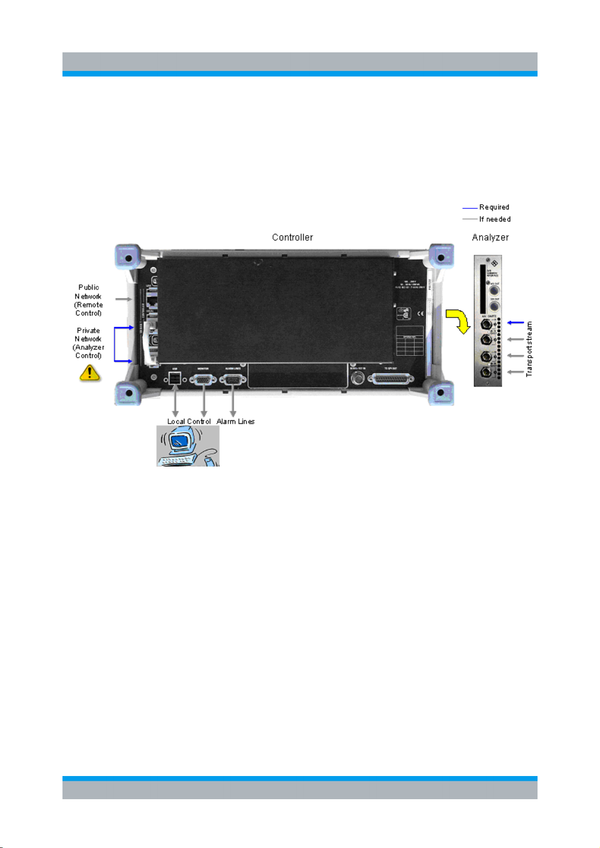
R&S DVM120/400 Introduction to the R&S DVM Basic System
Setting Up and Configuring a New R&S DVM Analysis System
2.2.1 System with the R&S DVM400
If a system contains only one R&S DVM400, the analyzer can be directly connected to
the controller. A crossed Ethernet cable such as the one supplied with the R&S DVM400
must be used in this case.
Figure 2-11: Connections of basic configuration of the R&S DVM 400
Quick Start Guide 2085.1939.62 - 06 2.17
Page 58

R&S DVM120/400 Introduction to the R&S DVM Basic System
Setting Up and Configuring a New R&S DVM Analysis System
2.2.2 System with the R&S DVM400 and R&S DVM120
In a system containing both the R&S DVM400 and R&S DVM120, the analyzers are
connected to the controller via an Ethernet hub. All 100 Mbit/s-compatible hubs in line
with standard IEEE802.3 can be used. We recommend to use hubs with automatic
identification of the line configuration. If such a hub is not available, uncrossed Ethernet
cables must be used.
Figure 2-12: Connections of basic configuration of the R&S DVM400 + R&S DVM120
Quick Start Guide 2085.1939.62 - 06 2.18
Page 59

R&S DVM50/100L/120/400 Introduction to the R&S DVM Basic System
Notes on the Operating System and Firmware Update
2.3 Notes on the Operating System and Firmware Update
2.3.1 Installation of the Software
Only software authorized by Rohde & Schwarz for use in the R&S DVM may be
installed. In case of doubt, please contact your local Rohde & Schwarz representative.
3 Changes to the system are only permissible in agreement with Rohde & Schwarz.
3 Updating the operating system, e.g. installing a service pack, is not allowed without
permission.
Otherwise the stability and performance of the system may be impaired. Rohde &
Schwarz shall not assume any liability for faults caused by impermissible manipulations
of the system.
For details on the installation refer to the release notes.
2.3.2 Write Protection of the Hard Disk
Model 02 instruments are equipped with write protection for the system's C:\ hard disk.
This function is no longer supported as of model 03. Secure continuous operation is
ensured even without write protection. You should also now refrain from activating write
protection for old instruments as well.
For model 02 instruments, you can do this using the functions described in the release
notes.
Quick Start Guide 2085.1639.62/2085.1939.62 - 07 2.19
Page 60

R&S DVM50/100L/120/400 Introduction to the R&S DVM Basic System
Notes on the Operating System and Firmware Update
2.3.3 Setting the System Time
You can set the system time using the Windows Desktop.
Setting the time of day:
1. Open the Windows XP dialog selecting
"Start" "Settings" "Control Panel" "Date and Time"
2. Set the date and time.
Setting the regional and language options:
1. Open the Windows XP dialog selecting
"Start" "Settings" "Control Panel" "Regional and Language Options"
2. Select the country on the "Regional Options" tab under "Standards and formats".
This setting will directly affect only the time and date display in Windows
XP Desktop. In order to synchronize the time references of the
connected analyzers, the application must be restarted after the time is
adjusted.
2.3.4 Checking the Analyzer Time
R&S DVM analysis boards have their own time reference. It is adjusted via an internal
NTP server (NTP = Network Time Protocol) to the system time of the controller.
Checking the synchronization:
1. Open the R&S DVM dialog secting "Help" "Analyzer Info" " Site Configuration"
2. On the "Analyzer Info" tab, select "Analyzer" and click on the "Show Info" button.
3. Under "Clock", check the time of day and status of the NTP synchronization.
Larger time deviations (e.g. after adjusting the system time) will require you to restart the
application.
Quick Start Guide 2085.1639.62/2085.1939.62 - 07 2.20
Page 61

R&S DVM50/100L/120/400 Introduction to the R&S DVM Basic System
Notes on the Operating System and Firmware Update
2.3.5 Linking the System Time to an External Time Server
Switch off the XP write protection before making a change!
It is possible to link the system time to an external time server of an IP network. To do
this, you need to enter its IP address in the C:\Windows\ntp.conf file and declare it as
“prefer”.
Figure 2.3-1: An excerpt from C:\Windows\ntp.conf
No link to an external server
…..
#
#
server 127.0.0.1 prefer
fudge 127.0.0.1 stratum 12
#
#
Link to NTP server with IP address
120.34.56.78
…..
#
#
server 120.34.56.78 prefer
server 127.0.0.1
fudge 127.0.0.1 stratum 12
#
#
Quick Start Guide 2085.1639.62/2085.1939.62 - 07 2.21
Page 62

R&S DVM50/100L/120/400 Introduction to the R&S DVM Basic System
Notes on the Operating System and Firmware Update
2.3.6 Configuring an External Keyboard
Switch off the XP write protection before making a change!
If so desired, you can connect an external keyboard to the USB interface. When
delivered, the R&S DVM is preconfigured for an English US keyboard.
Changing to a different country code:
1. Open the Windows XP dialog selecting
"Start" "Settings" "Control Panel" "Regional and Language Options"
2. On the "Language" tab, click the "Details" button to open the "Text Services and
Input Languages" dialog.
3. Click the "Add…" button to add the desired input language and desired keyboard
layout.
4. Select from the available options and confirm your choice.
5. If several keyboard codes are configured, you can select among them using the
Windows taskbar.
6. If no external keyboard is available, you can enter characters via a screen-based
keyboard using the mouse. The screen-based keyboard is activated using the
keyboard icon in the taskbar.
Quick Start Guide 2085.1639.62/2085.1939.62 - 07 2.22
Page 63

R&S DVM50/100L/120/400 Introduction to the R&S DVM Basic System
Notes on the Operating System and Firmware Update
2.3.7 Firmware Update
Switch off the XP write protection before making a change!
For step-by-step instructions how to install a new R&S DVM firmware, refer to the
release notes. If you do not follow these steps, there is a risk of losing information which
identifies the instrument configuration.
2.3.7.1 Starting the Application and Checking the Version
1. Start the R&S DVM application using the "DVM" icon on the desktop.
2. In the site tree (top left), the connected analyzer will be displayed with the "[?]" icon
so that it can be registered.
Note: It can take up to one minute for the analyzer to appear after an update.
3. Register the analyzer with the application:
a. Right-click on the icon and open the "Add Analyzer" dialog.
b. If desired, you can modify the proposed settings at this point. You can also wait
until later to do this.
c. Close the "Add Analyzer" dialog and the "Site Configuration" dialog.
4. Check the version of the instrument firmware:
In the R&S DVM application "Help" menu, select "About DVM" to open the
"About DVM" dialog.
5. Checking the analyzer version:
In the R&S DVM application "Help" menu, select "Analyzer Info…" to open the
"Site Configuration" dialog.
On the "Analyzer Info" tab, select the desired analyzer and then click the "Show
Info" button.
Quick Start Guide 2085.1639.62/2085.1939.62 - 07 2.23
Page 64
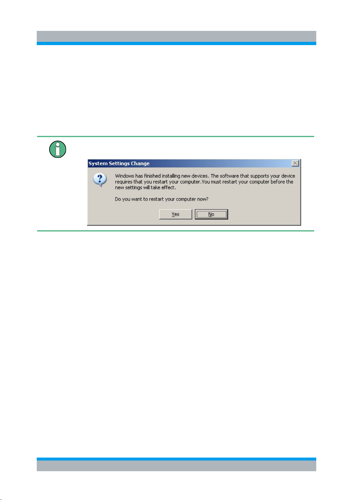
R&S DVM50/100L/120/400 Introduction to the R&S DVM Basic System
Notes on the Operating System and Firmware Update
2.3.8 Recovery and Backup Partition
R&S DVM provides a backup and recovery partition. A backup of the factory system
partition (C:\) is stored per default and can be recovered in case of a system crash.
In addition, backups of up to 5 images of partition C: can be stored. When recovered,
the system partition (C:/) is deleted, formatted and newly written. The data partition (D:\)
is not affected.
If the following message is displayed during backup or recovery, ignore
it and do not restart your instrument. Select "No".
2.3.8.1 Prerequisite for the Recovery and Backup
As a prerequisite of a backup/restore process, in the BIOS settings, the hardware
watchdog must be disabled. Otherwise the backup/restore process (which normally lasts
about 10 to 15 minutes) will be terminated and fail due to a reboot issued by the
watchdog after about 4 minutes.
Initiating the backup/restore process
1. Connect an external keyboard to the USB interface.
2. Switch the instrument off and on again.
Quick Start Guide 2085.1639.62/2085.1939.62 - 07 2.24
Page 65

R&S DVM50/100L/120/400 Introduction to the R&S DVM Basic System
Notes on the Operating System and Firmware Update
3. Boot into the BIOS settings by pressing the DEL key of the external keyboard in the
early boot phase when prompted at the bottom of the screen.
4. In the BIOS settings, select "Integrated Peripherals" using the
UPARROW/DNARROW keys of the external keyboard and open the following page
by pressing ENTER.
Quick Start Guide 2085.1639.62/2085.1939.62 - 07 2.25
Page 66

R&S DVM50/100L/120/400 Introduction to the R&S DVM Basic System
Notes on the Operating System and Firmware Update
5. In "Integrated Peripherals", change the "Watch Dog Timer Select" setting to
"Disabled".
6. Return to the main page and select "Save & Exit Setup" to store the changes and
proceed with the system boot.
7. In the boot screen, select "Backup/Recovery" and press ENTER.
8. Press ENTER to open the "Windows XP Embedded Recovery and Backup Partition"
dialog.
After a successful boot with the default option "Firmware" in the boot dialog or a restored
backup, the hardware watchdog will automatically be re-enabled by the R&S DVM
system software. Make sure that the required sequence as described above is not
interrupted for some reason. Otherwise restart at step 2.
Quick Start Guide 2085.1639.62/2085.1939.62 - 07 2.26
Page 67

R&S DVM50/100L/120/400 Introduction to the R&S DVM Basic System
Notes on the Operating System and Firmware Update
2.3.8.2 Displaying the Windows XP Recovery and Backup Partition Dialog
Before you perform a backup or recovery, make sure that the hardware
watchdog is disabled. For details see chapter 2.3.8.1.
1. In the boot screen, select "Backup/Recovery" and press ENTER.
2. Press ENTER to open the "Windows XP Embedded Recovery and Backup Partition"
dialog.
The dialog shows the available selections for the recovery and backup partition.
Quick Start Guide 2085.1639.62/2085.1939.62 - 07 2.27
Page 68

R&S DVM50/100L/120/400 Introduction to the R&S DVM Basic System
Notes on the Operating System and Firmware Update
To continue see one of the following chapters:
3 Backing Up the Current System Partition (chapter 2.3.8.3)
3 Recovering the Selected Version of System Partition (chapter 2.3.8.4)
3 Recovering the Factory Default (chapter 2.3.8.5)
3 Deleting Backups (chapter 2.3.8.6)
In the Windows XP Embedded Recovery and Backup Partition dialog
and all successive dialogs, you need a mouse to work with.
Quick Start Guide 2085.1639.62/2085.1939.62 - 07 2.28
Page 69

R&S DVM50/100L/120/400 Introduction to the R&S DVM Basic System
Notes on the Operating System and Firmware Update
2.3.8.3 Backing Up the Current System Partition
1. Make sure that the hardware watchdog is disabled. For details see chapter 2.3.8.1.
2. In the "Windows XP Embedded Recovery and Backup Partition" dialog, click "Make
Backup".
The "Make Backup" dialog is displayed. It shows the current versions of the firmware
and the software platform.
3. Click "Make Backup".
After the backup, the "Windows XP Embedded Recovery and Backup Partition"
dialog is displayed again.
4. Click "Exit and Shutdown".
5. Turn off/on the R&S DVM manually.
Quick Start Guide 2085.1639.62/2085.1939.62 - 07 2.29
Page 70
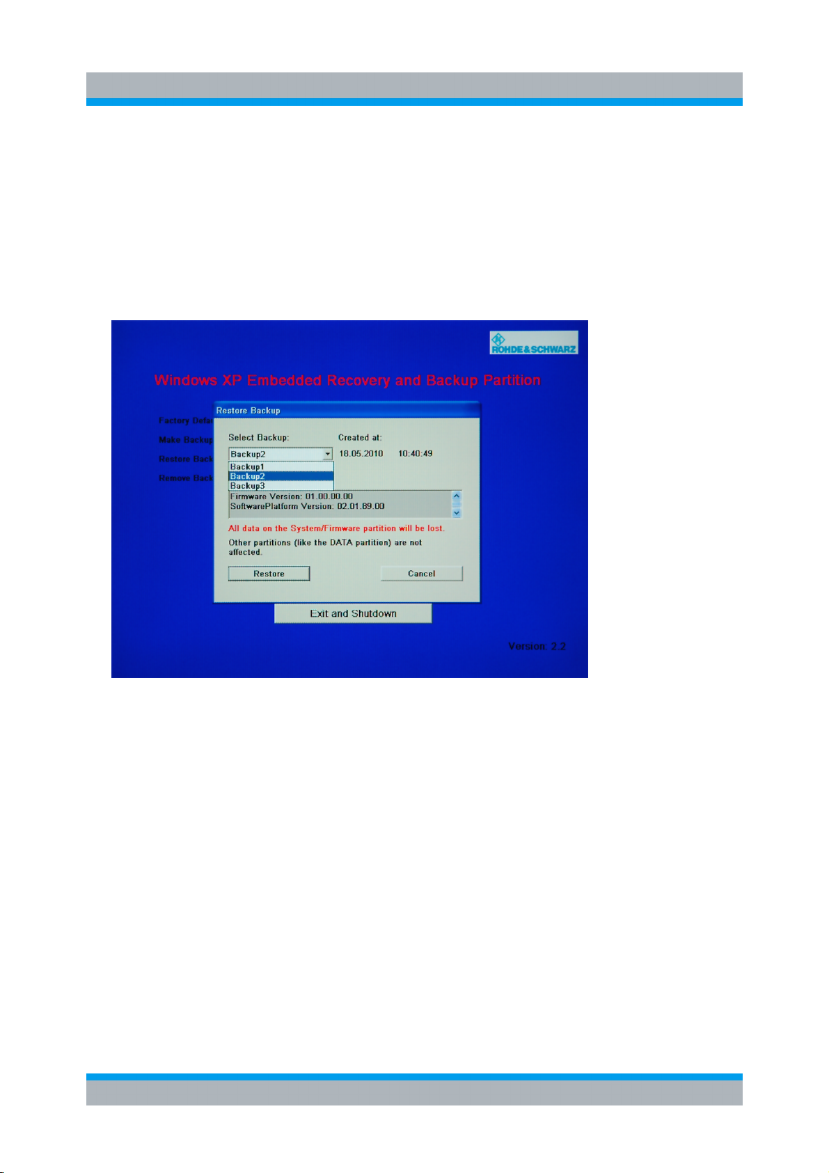
R&S DVM50/100L/120/400 Introduction to the R&S DVM Basic System
Notes on the Operating System and Firmware Update
2.3.8.4 Recovering the Selected Version of System Partition
1. Make sure that the hardware watchdog is disabled. For details see chapter 2.3.8.1.
2. In the "Windows XP Embedded Recovery and Backup Partition" dialog, click
"Restore Backup" to recover a selected version of the system partition.
The "Restore Backup" dialog is displayed. It shows the versions of the firmware and
the software platform of the backup displayed under "Select Backup".
3. Under "Select Backup", select the backup to be restored.
4. Click "Restore" and follow the instructions.
5. After the recovery, turn off/on the R&S DVM manually.
6. It is recommended to reinstall the R&S DVM firmware after restoring any backup.
a. Uninstall by selecting "Start" "Settings" "Control Panel" "Add or Remove
Programs" and removing “R&S DVM100” or “R&S DVM400” in the Windows XP
dialog.
b. Install the R&S DVM firmware afterwards as described in the release notes.
Quick Start Guide 2085.1639.62/2085.1939.62 - 07 2.30
Page 71

R&S DVM50/100L/120/400 Introduction to the R&S DVM Basic System
Notes on the Operating System and Firmware Update
2.3.8.5 Recovering the Factory Default
1. Make sure that the hardware watchdog is disabled. For details see chapter 2.3.8.1.
2. In the "Windows XP Embedded Recovery and Backup Partition" dialog, click "Factory
Default" to recover the factory version of the system partition.
The "Factory Default" dialog is displayed. It shows the versions of the firmware and
the software platform on delivery.
3. Click "Restore now" and follow the instructions.
4. After the recovery, turn off/on the R&S DVM manually.
5. It is recommended to reinstall the R&S DVM firmware after restoring any backup.
a. Uninstall by selecting "Start" "Settings" "Control Panel" "Add or Remove
Programs" and removing “R&S DVM100” or “R&S DVM400” in the Windows XP
dialog.
b. Install the R&S DVM firmware afterwards as described in the release notes.
Quick Start Guide 2085.1639.62/2085.1939.62 - 07 2.31
Page 72

R&S DVM50/100L/120/400 Introduction to the R&S DVM Basic System
Notes on the Operating System and Firmware Update
2.3.8.6 Deleting Backups
On the recovery partition, you can store up to five backups in addition to the factory
default. To provide space for new backups, you may need to remove older backups. The
factory default cannot be deleted.
1. Make sure that the hardware watchdog is disabled. For details see chapter 2.3.8.1.
2. In the "Windows XP Embedded Recovery and Backup Partition" dialog, click
"Remove Backup" to delete a selected backup.
The "Remove Backup" dialog is displayed. It shows the versions of the firmware and
the software platform of the selected backup.
3. Under "Select Backup", select the backup to be deleted.
4. Click "Remove".
After the deletion, the R&S DVM returns to the "Remove Backup" dialog as long as
backups are still available. If the last backup is deleted, the "Windows XP Recovery
and Backup Partition" dialog is displayed again.
5. Click "Cancel" to return the "Windows XP Embedded Recovery and Backup Partition"
dialog.
6. In the "Windows XP Embedded Recovery and Backup Partition" dialog, click "Exit
and Shutdown".
7. Turn off/on the R&S DVM manually.
Quick Start Guide 2085.1639.62/2085.1939.62 - 07 2.32
Page 73

R&S DVM50/100L/120/400 Introduction to the R&S DVM Basic System
Launching the R&S DVM Analyzer Application and Creating a Basic Configuration
2.4 Launching the R&S DVM Analyzer Application and Creating a Basic Configuration
2.4.1 Launching the R&S DVM Analyzer Application
After power-up, the R&S DVM application is launched automatically.
/ If the application was terminated manually, it can be restarted any time by double-
clicking the R&S DVM program icon on the desktop.
/ If you do not see the R&S DVM program icon on the desktop, you can find the
program under "Start" "Programs" "Rohde & Schwarz" "DVM"
2.4.2 Creating a Basic Configuration
After booting, the instrument automatically launches the R&S DVM application. If the
currently used system has never been configured before, perform a basic configuration
as described below:
1. In the "File" menu, select “New Site Configuration...”.
2. Select the desired TV standard from the list and specify the memory location and a
name for the configuration file.
3. Start the configuration with "OK".
Quick Start Guide 2085.1639.62/2085.1939.62 - 05 2.33
Page 74

R&S DVM50/100L/120/400 Introduction to the R&S DVM Basic System
Meas. Group
Launching the R&S DVM Analyzer Application and Creating a Basic Configuration
Figure 2.4-1: Site tree for an R&S DVM100/DVM120 system with an analysis board having two
inputs
After successful configuration, all installed TS inputs are displayed in the site tree. The
system is now ready for operation. The configuration can be adapted as required with
the aid of corresponding setup menus. Appropriate names can be assigned to the inputs
in the site tree, the order of the inputs can be determined and inputs can be organized in
folders.
2.4.3 The R&S DVM Measurement Screen and its Operating Elements
Figure 2.4-2: The R&S DVM measurement screen
Taskbar
Site Tree
TS Tree
Selection
Meas. Path
Meas. Selection
Results Display
Button for
Measurement
Control
Meas.
Status Bar
Quick Start Guide 2085.1639.62/2085.1939.62 - 05 2.34
Page 75

R&S DVM50/100L/120/400 Introduction to the R&S DVM Basic System
Launching the R&S DVM Analyzer Application and Creating a Basic Configuration
Table 2.4-1: Elements on the R&S DVM measurement screen
Element Description
Taskbar Menus for control and configuration of complete system
File – Loading and storing of instrument settings and measured values; printout of
measurement results
View – Selection of measurement group
Setup – Setting of instrument parameters
Help – User support
Site Tree
TS Tree
Measurement
Group Selection
Measurement
Path
Measurement
Selection
Results Display Result display for selected measurement.
Button for
Measurement
Control
Measurement
Status Bar
List of all signal inputs with current monitoring status. An input is selected by doubleclicking the name. In addition to the site name, the header contains the total status of
all signal inputs.
List of elements of transport stream present at the selected input. The header
contains the total status of this transport stream in addition to the input name.
Button for direct selection of a measurement group.
Display of selected measurement with measurement path.
Tabs for choosing a measurement from the selected measurement group.
Control of selected measurement.
Display of relevant settings and states of the selected measurement.
Quick Start Guide 2085.1639.62/2085.1939.62 - 05 2.35
Page 76
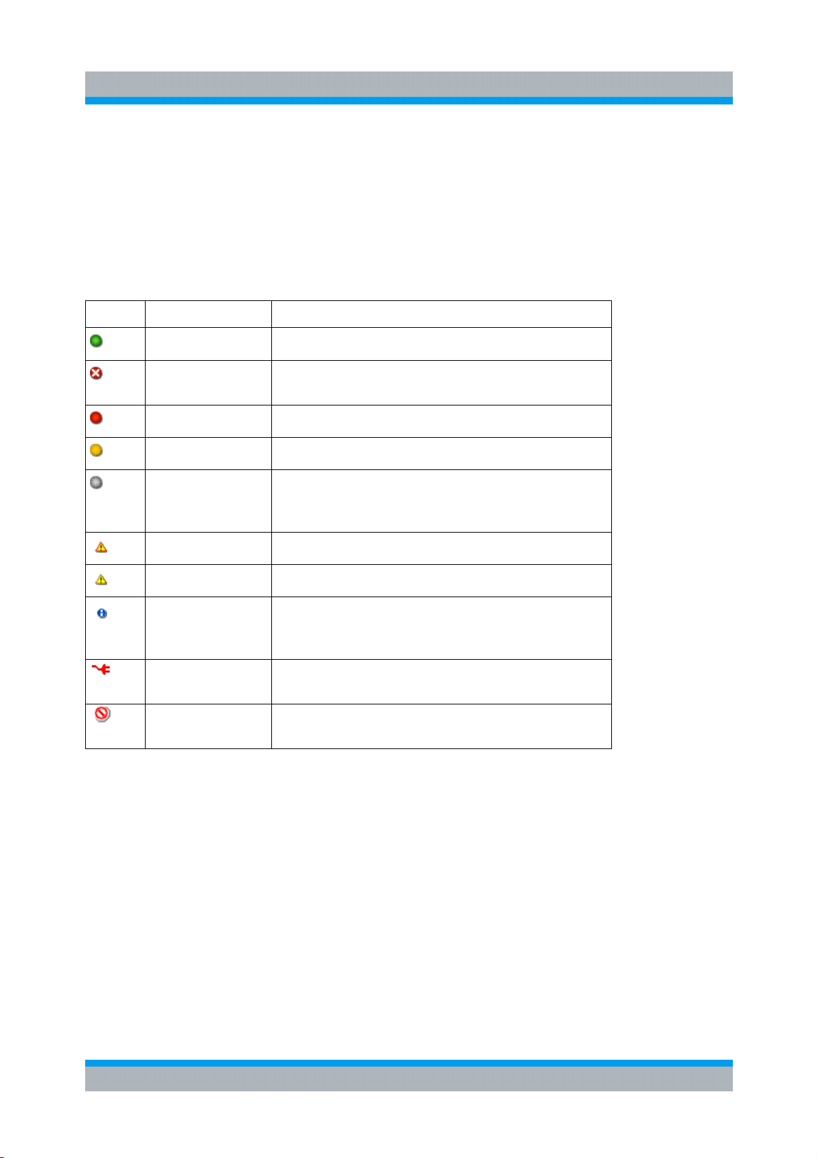
R&S DVM50/100L/120/400 Introduction to the R&S DVM Basic System
Launching the R&S DVM Analyzer Application and Creating a Basic Configuration
2.4.4 Indication of Signal and Error States
A key feature of the R&S DVM is the indication of signal and error states of the applied
transport streams. The signaled states are derived from the monitoring results. An
update is therefore only performed for signal inputs for which monitoring is switched on.
The table below gives an overview of signaling states.
Table 2.4-2: Symbols used to indicate alarm ad error states
Symbol Description Status
Green lamp/button No alarm
Red lamp/button
with white cross
Red lamp/button Alarm currently present
Yellow lamp/button Alarm occurred but is now gone
Grey lamp/button
Red triangle Warning currently present
Yellow triangle Warning occurred but is now gone
I on blue circle
Red connector
Red stop
No transport stream found
No analysis result. This lamp is always displayed
together with another indication such as "monitoring
stop" or "data link to analyzer interrupted".
Information available (displayed only under Monitoring
and in TS tree elements, not in higher-order folders of
the TS tree and not in the site tree)
Data link to analyzer interrupted
(always occurs together with a grey lamp)
Monitoring is stopped
(always occurs together with a grey lamp)
Several elements of the site tree and the input tree can be organized in a folder. If status
information is available for one or more elements, the information is displayed in the
higher-order folder when the element folder is closed.
Quick Start Guide 2085.1639.62/2085.1939.62 - 05 2.36
Page 77

R&S DVM50/100L/120/400 Introduction to the R&S DVM Basic System
Launching the R&S DVM Analyzer Application and Creating a Basic Configuration
Examples
Table 2.4-3: Symbols for indicating alarm and error states in folders
Symbol
Description Status
Closed folder
Closed folder with
red lamp +
yellow triangle +
red stop
No alarm, warning or info message is present for the
contained elements.
The following applies to one or more signal inputs of this
folder:
An alarm signal is present
A warning has occurred
The measurement has been stopped
Closed folder with
yellow lamp +
red connector
The following applies to one or more signal inputs of this
folder:
An alarm occurred data link to any analyzer
interrupt 1
The measurement has been stopped
Closed folder with
grey lamp +
red connector
The following applies to all signal inputs of this folder:
No analysis result
Data link to analyzer interrupted
Quick Start Guide 2085.1639.62/2085.1939.62 - 05 2.37
Page 78

R&S DVM50/100L/120/400 Introduction to the R&S DVM Basic System
Launching the R&S DVM Analyzer Application and Creating a Basic Configuration
2.4.5 The R&S DVM Measurement Groups
The following R&S DVM measurement groups can be directly selected via icons on the
screen.
Table 2.4-4: Overview of the R&S DVM measurement groups
Symbol
Measurement
Group
Topology
Signal Interface
Monitoring
Property
Combined signaling of monitoring status for all configured signal
inputs on a background display. Every input is represented by a
separate icon. The position of the icons can be configured. The
background display can be customized and loaded.
Measurement of the physical characteristics of the input signal.
The type of measurement depends on the interface used.
Display of monitoring status of a selected input with the following
views:
Statistics & Log – number and type of faults indicated as a sum
and listed in chronological sequence in a report
Data Rate – graphical display of data rate of individual transport
stream elements
Table Repetition – graphical display of repetition rate of
SI/PSI/PSIP tables
Template Monitoring (TS Template Monitoring option) – display
of the template used as tree with marks that indicate the
deviations detected.
Every configured input is separately monitored. The results are
displayed in the form of a sum message in the site tree and under
Topology.
Interpreter
(Option
In-depth
Analysis)
Advanced
(Option
In-depth
Analysis)
Display and interpretation of selectable data in the transport
stream with the following options:
Packet Interpreter – display of individual transport stream
packets
Table/PES Interpreter – display of selectable SI/PSI/PSIP
tables or PES headers
Header Map – list of transport stream headers in chronological
sequence
TS List – table of all transport stream elements with key
specifications
In-depth measurements for timing specifications of transport
stream:
PCR Jitter Analysis - analysis with recording of PCR repetition
times
PTS Analysis – analysis of PCR/PTS shift and PTS intervals
Quick Start Guide 2085.1639.62/2085.1939.62 - 05 2.38
Page 79

R&S DVM50/100L/120/400 Introduction to the R&S DVM Basic System
Launching the R&S DVM Analyzer Application and Creating a Basic Configuration
Symbol
Measurement
roup
G
Data Broadcast
(Option
DVB Data
Broadcast
Analysis)
Streaming Start of applications for processing individual elements.
AV Decoder
(Option Video
and Audio
Hardware
Decoder)
Property
Data Broadcast Analysis:
Overview - Displays all descriptors that refer to the selected
data service in the created transport stream.
Interpreter - Displays the contents of an element in the protocol
tree. The display depends on the service and on the type of
element selected.
Raw Data - Displays the raw data of the element selected
Timing – Data and Object Carousel Timing analysis
Video Player (media player – video live picture decoding.
Elementary Stream Analyzer – video elementary stream
analysis with the optional R&S DV-ESA software.
DVB-H Time Slice Analyzer – unpacking and processing of
DVB-H content with the Data Broadcast Analysis R&S DVMK11 option.
Write to file – function for storing individual TS elements on
hard disk.
Control of the integrated Video and Audio Hardware Decoder:
TV – information about decoded video and audio signal.
Display of the video signal on the integrated display (DVM400
only)
Decoder Status Info – status information about the hardware
decoder
Quick Start Guide 2085.1639.62/2085.1939.62 - 05 2.39
 Loading...