

Page 1

Test and Measurement
Division
Operating Manual
VECTOR NETWORK
ANALYZER
ZVR / ZVRE / ZVRL
1127.8551.61/.62
1127.8551.51/.52
1127.8551.41
ZVC / ZVCE
1127.8600.60/.61/.62
1127.8600.50/.51/.52
ZVM
1127.8500.60
ZVK
1127.8651.60
Volume 1
Operating Manual consists of 2 volumes
Printed in the Federal
Republic of Germany
1127.8700.12-03- 1
Page 2

Page 3

ZVx Tabbed Divider Overview
Volume 1 Volume 2
Contents Contents
Index Index
Data Sheet
Supplements
Safety Instructions Safety Instructions
Certificate of Quality Certificate of Quality
EC-Certificate of Conformity EC-Certificate of Conformity
Support Center Address Support Center Address
List of R&S Representatives List of R&S Representatives
Tabbed Divider Tabbed Divider
1 Preparation for Use 1 Remote Control
2 Manual Operation 2 Maintenance and Troubleshooting
3 Testing the Rated Specifications
4 Annex A: Interfaces
5 Annex B: List of Error Messages
6 Annex C: List of Commands
7 Annex D: Programming Examples
8 Annex E: Emulations
1127.8700.12 RE E-1
Page 4

Page 5

Test and Measurement
Division
Release Notes
Firmware Version 3.52
for ZVR/ZVRE/ZVRL/ZVC/ZVCE/ZVM/ZVK
1112.7990.39
Printed in the Federal
Republic of Germany
1112.8050.52-17- 1
Page 6

Page 7

ZVx Firmware Version 3.52
Contents
General Information..........................................................................................................................1
Manual for ZVR Family.................................................................................................................. 1
Update Procedure.........................................................................................................................1
Initial Steps.................................................................................................................................... 1
Documentation of Firmware Modifications.................................................................................... 1
1 Firmware Update........................................................................................................................... 2
System Requirements...................................................................................................................2
Preparations for Update................................................................................................................2
Contents of Firmware Update Kit..................................................................................................2
Update Procedure.........................................................................................................................2
2 New Features, Improvements and Modifications...........................................................5
New Features................................................................................................................................ 5
Improvements ...............................................................................................................................6
Modifications ................................................................................................................................. 6
3 Bug Fixes.........................................................................................................................................7
4 Extensions to Operating Manual............................................................................................8
5 New IEEE-Bus Commands..................................................................................................... 20
6 Special Features......................................................................................................................... 28
1112.8050.52 I.1 E-17
Page 8

Page 9

ZVx Firmware Version 3.52
General Information
Manual for ZVR Family
The analyzers of the ZVR family are supplied with the following manual:
"Operating Manual – Vector Network Analyzer" ZVR/E/L, ZVC/E, ZVM, ZVK
Order No. 1127.8700.xx-03-
where xx 11 (German)
12 (English)
13 (French)
19 (English, US letter format)
Update Procedure
The update instructions given in sec tion 1 of this release note are to the latest state; any deviating
instructions in the operating manual are to be ignored.
If you have received this document together with a new analyzer, you can skip section 1.
If you have received the document together with a firmware update kit or as a download together with
a self-extracting archive file, you should read section 1.
Initial Steps
If you work with a ZVR analyzer for the first time, it is recomm ended to read the operating m anual to
familiarize yourself with the unit.
If you are already familiar with the instrument, this document informs you about new features.
Documentation of Firmw a r e Modifications
This document covers firmware modifications that are not part of the current operating manual.
1112.8050.52 1 E-17
Page 10

Firmware Version 3.52 ZVx
1 Firmware Update
System Requirements
None
Preparations for Update
No preparations are required.
Contents of Firmware Update Kit
The update kit comprises the following:
• Five 3.5"/1.44 Mbyte disks labelled as follows:
Disk 1 : „V3.52 DISK 1“
Disk 2 : „V3.52 DISK 2“
Disk 3 : „V3.52 DISK 3“
Disk 4 : „V3.52 DISK 4“
Disk 5 : „V3.52 DISK 5“
• This document
Update Procedure
1. If you have received a self-extracting archive file per e-mail or as a download
a set of disks must first be created from the archive file.
Proceed as follows:
½ Check if you have received all files.
disk1.bin self extracting ZIP file, used to generate update disk 1
data2.cab packed contents of disk 2, automatically unpacked during FW update
data3.cab packed contents of disk 3, automatically unpacked during FW update
data4.cab packed contents of disk 4, automatically unpacked during FW update
data5.cab packed contents of disk 5, automatically unpacked during FW update
disk_d.bin this document packed
½ Keep five DOS-formatted 3.5" / 1.44 Mbyte disks ready.
½ Label disks as follows:
V3.52 DISK 1
V3.52 DISK 2
V3.52 DISK 3
V3.52 DISK 4
V3.52 DISK 5
½ Create a temporary directory on your PC (e.g. ZVRTEMP on C:\). For this you require about
3 Mbytes of free memory on your hard disk.
½ Copy file disk1.bin to this temporary directory.
½ Rename file disk1.bin to disk1.exe.
1112.8050.52 2 E-17
Page 11

ZVx Firmware Version 3.52
½ Execute disk1.exe, e.g. by using the following command sequence for Windows95/NT:
<CTRL><ESC> - RUN – C:\ ZVRTEMP \DISK1 - <ENTER> (English version) or
<CTRL><ESC> - AUSFÜHREN – C:\ ZVRTEMP \DISK1 - <ENTER> (German version).
The files are extracted.
½ Delete file disk1.exe in the temporary directory.
The temporary directory should contain the following files:
_inst32i.ex_ _isdel.exe _setup.dll _sys1.cab _user1.cab
data.tag data1.cab lang.dat layout.bin os.dat
readme.txt setup.exe setup.ini setup.ins setup.lid
½ Copy all files to update disk 1 (V3.52 DISK 1).
Check if all files are on the disk with their correct names. In particular, the underscores ("_" as in
"_inst32iex_") are essential for a successful update.
½ The contents of the other 4 disks are already in the format needed for the update. Files
data2.cab,..., data5.cab must be copied to the corresponding disks DISK2, ..., DISK5.
The disks are now ready, and you can continue with section 2 "If you have received a firmware
update kit on a disk ...".
Notes: If any error messages are output during creation of a dis k , the ins tallation proc es s for the
disk in question must be repeated. Before re-creating the disk, check if the write
protection of the disk has been removed.
File disk_d.bin contains this document in pdf format. To unpack the document proceed as follows:
½ Copy disk_d.bin to the temporary directory.
½ Rename the file to disk_d.exe.
½ Execute disk_d.exe, e.g. by using the following command sequence for Windows95/NT:
<CTRL><ESC> - RUN – C:\ ZVRTEMP \DISK_D - <ENTER> (English version)
or<CTRL><ESC> - AUSFÜHREN – C:\ ZVRTEMP \DISK_D - <ENTER> (German version)
1112.8050.52 3 E-17
Page 12

Firmware Version 3.52 ZVx
2. If you have received a firmware update kit on a disk ...
You can load the firmware directly from the disk to your network analyzer.
½ Insert the disk DISK 1 into the drive.
½ Press the SETUP key and change to the side menu by pressing ⇒ key.
½ Press the FIRMWARE UPDATE softkey.
½ Start the update by pressing the UPDATE softkey and follow the instructions on the analyzer
display.
First, the contents of the update disks are copied to the hard dis k of the instrument. Then the
files are extracted and copied in the directories accordingly. After the ex traction, the instrument
is rebooted.
The firmware update is complete.
The previous firmware version may be restored using softkey RESTORE.
3. If problems occur during the firmware update ...
The new firmware can if necessary also be loaded under NT. This should be done only with an
external keyboard and a mouse. Log-in has to be made using the ADMINISTRATOR f unction, and
the device firmware closed.
Log in as administrator.
½ Press key combination ALT SYSREQ to switch to NT screen if not yet displayed.
½ Call up the NT task bar START – SHUT DOWN.
½ Select ‘Close all programs and logon as different user’.
½ Hold the SHIFT key down and press the OK key to leave the input window until the login window
appears.
½ Release the SHIFT key as soon as the login window appears.
½ Now enter administrator as user name and 894129 as password.
Close the device firmware:
½ Press the keys CTRL ALT DEL on the external keyboard simultaneously.
½ Select the Task Manager.
½ Select the Application Rohde&Schwarz ZVR NT Interface and terminate it with End Task.
Now the new firmware can be loaded:
½ Insert DISK 1 into drive A:
½ Start the installation with START RUN A:SETUP. You will be prompted to insert the rem aining
disks one after the other.
After loading the software, the operating system is rebooted. T hen change bac k from administrator
to instrument (password ins trum ent) for the login. T his is done in the s ame way as changing of login
to administrator.
Note: If the firmware is installed in this way, the previous version cannot be restored.
1112.8050.52 4 E-17
Page 13

ZVx Firmware Version 3.52
2 New Features, Improvements and Modifications
New Features
• Support of waveguide calibration:
For this purpose, two new softkeys were added to the menu CAL → CAL KITS → right side menu:
WAVEGUIDE (position 6) and CUTOFF FREQUENCY (position 7)
• Deinstallation of calibration kits:
A new softkey is available in the menu CAL → CAL KITS:
UNINSTALL KITS (position 10)
• New SCPI commands:
- Reading out and modification of system error calibration and power calibration
- Support of waveguide calibration
- Query of electrical length, mechanical length and phase delay
• Support of additional, external devices:
- Generator SML (Rohde & Schwarz)
- Generator SMR30, SMR50, SMR60, SMR30B11, SMR50B11, SMR60B11 (Rohde & Schwarz)
- Generator HP8648 A/B/C/D (Agilent)
- Generator HP83650A (Agilent)
- Power Meter NRP (Rohde & Schwarz)
- Power Meter ML2438A (Anritsu)
- Power Meter E4417A (Agilent)
- Power Meter EPM-441A (Agilent)
-
1112.8050.52 5 E-17
Page 14

Firmware Version 3.52 ZVx
Improvements
• When reading and writing system error correction data and level correction data in the REAL64
format, an error message is output.
Affected IEC/IEEE bus commands:
SENSe[1..4]:CORRection:DATA
SENSe[1..4]:CORRection:POWer:DATA
SOURce[1..4]:POWer:CORRection:DATA
• If a waveguide calibration (WAVEGUIDE = ON) is performed via IEC/IEEE bus with a CUTOFF
FREQUENCY that is higher than the START FREQUENCY, an error message is now output
because this action is not permitted.
• Omission of unnecessary level calibration interpolation (improves performance especially during
operation via the IEC/IEEE bus).
• The CALC:MARK:FUNC:RES? IEC/IEEE bus query now yields 10 significant marker points
(previously only 6).
• Improvement of signal quality of R&S SMR generators (SMR20/27/30/40/50/60,
SMR20/27/30/40/50/60B11) in TTL mode.
(This requires an SMR firmware version ≥1.26.)
• Generators currently not used are switched to RF OFF. This prevents erroneous measurements
and avoids disconnecting any cables.
Examples:
- During power calibration of the internal generator, any external generators connected to the
instrument and set to REMOTE are switched to RF OFF.
- This applies analogously to the calibration of an external generator. In this case, the internal ge-
nerator (and, if available, a second external generator connec ted and set to REMOTE) is switched
to RF OFF.
- W hen a COMP/SOI/TOI, arbitrary or mixer measurem ent is switched off, the external generators
used in the measurement are set to RF OFF.
Modifications
• New softkeys or softkeys shifted to another position in menu CAL → CAL KITS:
- Softkey USER CONN NAME now at position 9 of right side menu
- Softkey USER CONN IMPEDANCE now at position 10 of right side menu
- New softkey UNINSTALL KITS at position 10 of main menu
- New softkey WAVEGUIDE at position 6 of right side menu
- New softkey CUTOFF FREQUENCY at position 7 of right side menu
1112.8050.52 6 E-17
Page 15

ZVx Firmware Version 3.52
3 Bug Fixes
• In the ACTIVE xx STANDARDS table, the entries for the OPEN standards are again available when
a calibration is performed.
• System error correction data sets generated with a version <3.50 can now be recalled again
(RECALL).
• The power correction function has been improved:
- External power calibration is reliably activated with COMP/SOI/TOI measurements.
- An existing power calibration can be used again in power sweeps and in time sweeps.
• The normal user (logged on under the name "INSTRUMENT") has write access again to the
directory AUTOKAL, so the AutoCal function works again.
• Commanding the OFFSET SHORT standards
(SENSe[1..4]:CORRection:COLLect:ACQuire:OSHORT1 or OSHORT2) in case of waveguide
calibration (WAVEGUIDE = ON) is possible again.
• Errors were corrected in the following SCPI commands:
- SENS:FUNC?
- SOURce:POWer:[LEVel]:[IMMediate]:CAMPlitude
• Softkeys that were not visible are now available again:
- Menu MEAS → USER DEF’D S-PARAMS: softkeys USER DEF’D S-PARAMS and USER DEF ACTIVE
- Menu CAL → START NEW CAL → FULL ONE PORT → BOTH PORTS: softkey 2.92 mm FEMALE
- Menu MEAS → WAVE QANTITY: softkey DRIVE PORT
1112.8050.52 7 E-17
Page 16

Firmware Version 3.52 ZVx
4 Extensions to Operating Manual
Characteristics of Calibration Standards (Re section 2.15.1.3)
The MODIFY CAL KIT softkey opens a m enu for the management of c alibration kits for the individual
connector families.
Exact knowledge of the calibration standards is a pr erequisite for a accurate system-error calibr ation.
More precisely, the calibration is based on the knowledge of those S-parameters of the standards which
are assumed to be known for the applied calibration method. These S-parameters are derived from
physical models which contain one or more par am eters ( such as the electric al length) depending on the
type of standard.
In addition to these physical parameters, there are three des cription fields for each standar d listing the
assignment of the standard and further information for the user.
1. Standard type: The type depends on the kind of standard (e.g. open c ircuit, short circuit, throughconnection) and the sex of the connectors. Example: THROUGH (MF) denotes a throughconnection with a plug at one and a socket at the other port. The standard type determines the
physical description model and therefore the param eters which can be edited. Up to four individual
standards with different param eters can be def ined for one standar d type. Only one of them can be
selected (active) at one time.
2. Calibration kit (KIT): A calibration kit is an assembly of real, physical calibration standards.
Calibration kits are supplied by Rohde & Schwarz as an accessory for network analyzers. The
parameters of the standards in a calibration kit are stored on a floppy disk which can be r ead in via
the INSTALL NEW KIT softkey. Kits for coaxial connector families usually do not contain all possible
standard types of these families but only a subset comprising the types which are most frequently
used in coaxial technology. Calibration kits can be user-defined as well. Using the ACT IVATE KIT
softkey, the standards of a calibration kit can be selected altogether by just one keystroke.
3. Serial number (SERIAL #): All st andards of a c alibration kit are f actory-labelled with the same s erial
number so they can be assigned unambiguously to this kit. The serial number helps to avoid
confusion between standards of the same type from different calibration kits which might have
different physical parameters.
1112.8050.52 8 E-17
Page 17

ZVx Firmware Version 3.52
V
N
N
ZV-Z21
ZV-Z21
ZV-Z21
ZV-Z26
ZV-Z26
ZV-Z21
ZV-Z21
ZV-Z21
ZV-Z21
ZV-Z21
ZV-Z21
ZV-Z41
ZV-Z41
OPEN PORT
OPEN PORT
CAL CAL - CAL KITS submenu:
CAL KITS
USER
ACTIVE N 50Ω STANDARDS
STANDARD TYPE
THROUGH (MM)
THROUGH (FF)
THROUGH (MF)
LINE 1 (MM)
LINE 1 (FF)
LINE 1 (MF)
LINE 2 (MM)
LINE 2 (FF)
LINE 2 (MF)
ATTENUATION (MM)
ATTENUATION (FF)
ATTENUATION (MF)
SYMM NETWORK (MM)
SYMM NETWORK (FF)
SYMM NETWORK (MF)
OPEN (M)
OPEN (F)
SHORT (M)
SHORT (F)
REFLECT (M)
REFLECT (F)
MATCH (M)
MATCH (F)
SLIDING MATCH (M)
SLIDING MATCH (F)
NOTE: The connector sex refers
to the ports of the standards!
KIT
CAL KITS
CONNECTOR
TYPE
ACTIVATE
KIT
MODIFY
STANDARDS
IEW
ACTIVE STD
CREATE
INST FILE
RESTORE
INSTD KITS
LIST
INSTD KITS
INSTALL
NEW KIT
USER CON
NAME
USER CON
IMPEDANCE
Selecting the connector families
After pressing the CAL KITS softkey, the ACTIVE XX STANDARDS selection table is
displayed, where XX denotes the connector family selected. By default, the
connector family of the test se t ports is selected. T he table gives an overview of the
active standards of the connector family:
• The STANDARD TYPE colum n lists all standard types which are required f or the
calibration procedures of the respective type of instrument.
• The KIT column indicates to which calibra tion kit the currently selected physical
standard belongs. By default, for standard types contained in the calibration kits
offered by Rohde & Schwarz, the designation of the corresponding kit is also
displayed. Although typical parameter values are pre- defined f or these s tandards ,
the individual parameters for eac h calibration kit, which are supplied on a floppy,
should be read in for the sake of maximum accuracy (see INSTALL NEW KIT
softkey). The predefined standards without calibration kit assignment are
assumed to be ideal.
1112.8050.52 9 E-17
Page 18

Firmware Version 3.52 ZVx
The cursor can be used to select the standard type the softkeys MODIFY
STANDARDS and VIEW ACTIVE STD refer to.
For polarized connector families, three types exist for each two-port standard,
namely male/male (MM), female/female (FF), and male/female (MF). One-port
standards are provided as male (M) and female ( F). For non-polarized connectors,
such as PC 7, all standards are contained only once in the table.
If a calibration method requires to measure two standards with the same polarity
simultaneously, their characteristics are assumed to be identical. This applies, e.g.,
to the TOM-X calibration method if the OPEN BOTH PORTS measurement is
performed.
The following types of standards are provided for the various types of network analyzers. Due to the
restricted calibration facilities of the Z VRE, ZVCE and ZVRL c ompared to the ZVR, ZVC, ZVK and ZVM,
a reduced set of standards is required only.
Table: Standard types for the network analyzers
ZVR, ZVC, ZVK, ZVM ZVRE, ZVCE, ZVRL
THROUGH THROUGH through-connection
LINE 1 line 1 for TRL calibration procedure
LINE 2 line 2 for TRL calibration procedure
ATTENUATION unknown matched attenuator
SYMMETRIC NETWORK unknown mismatched reflection-symmetric
OPEN OPEN open circuit
SHORT SHORT short circuit
OFFSET SHORT OFFSET SHORT additional short circuit for waveguide calibration
REFLECT unknown mismatched one-port standard
MATCH MATCH broadband termination
SLIDING MATCH SLIDING MATCH sliding load
two-port standard
1112.8050.52 10 E-17
Page 19

ZVx Firmware Version 3.52
V
N
N
CAL CAL - MODIFY CAL KIT - SELECT KIT submenu:
CAL KITS
CONNECTOR
TYPE
ACTIVATE
KIT
MODIFY
STANDARDS
IEW
ACTIVE STD
RESTORE
INSTD KITS
LIST
INSTD KITS
INSTALL
NEW KIT
USER CON
NAME
USER CON
IMPEDANCE
CONNECTOR
TYPE
Ω
Ν 50
Ω
Ν 75
PC 7
SMA
PC 3.5
SEXLESS
USR CONN 1
USR CONN 2
The CO NNECTOR TYPE softkey calls a m enu for selecting the
connector family shown in the ACTIVE XX STANDARDS table.
The type and order of the connectors shown in this menu are
different for the different models of the Z Vx family. The connec tor
types used for the instrument test ports always come at the
uppermost position. This is also the default setting.
The following connector families are provided:
• N 50 Ω,
• N 75 Ω,
• PC 7,
• SMA,
• PC 3.5,
• 2.92 mm.
In addition two connector families can be arbitrarily defined,
namely:
• SEXLESS USR CONN 1
• USR CONN 2
Only the two user-defined connector families can be configured
for waveguide calibration.
Ω
Ν 50
Ν 75 Ω
PC 7
SMA
PC 3.5
The N 50 Ω softkey displays the table ACTIVE N 50 Ω STANDARD .
The N 75 Ω softkey displays the table ACTIVE N 75 Ω STANDARDS.
The PC 7 softkey displays the table ACTIVE PC 7 STANDARDS.
The SMA softkey displays the table ACTIVE SMA STANDARDS.
The PC 3.5 softkey displays the table ACTIVE PC 3.5 STANDARDS.
1112.8050.52 11 E-17
Page 20

Firmware Version 3.52 ZVx
SEXLESS
USR CONN 1
The SEXLESS USR CONN 1 softkey displays the table ACTIVE USER CONN 1
STANDARDS. The connector family SEXLESS USR CONN 1 which can be user-
defined is not polarized (similar to PC 7) and particularly suited for non-coaxial cable
systems such as microstr ip.
The two user-defined connector f amilies SEXLESS USR CONN 1 and USR CONN 2
can also be used for waveguide calibration (refer to WAVEGUIDE softkey
description). As waveguides are as a rule not polar ized, SEXLESS USR CONN 1 is
to be preferred to USR CONN 2.
The name of this c onnector family (USER CONN 1 by default) can be modified via
the USER CONN NAME softkey.
USR CONN 2
The USR CONN 2 softk ey displays the table ACTIVE USER CONN 2 STANDARDS.
Unlike SEXLESS USR CONN 1, this us er-defined connector fam ily is polarized and
therefore suited for the coaxial connectors that are not pre-defined in the
CONNECTOR TYPE menu. The connector family USR CONN 2 can also be used
for waveguide calibration.
The name of this c onnector family (USER CONN 2 by default) can be modified via
the USER CONN NAME softkey.
CAL CAL - CAL KITS submenu:
ACTIVATE
KIT
The ACTIVATE KIT softkey displays the selection table ACTIVATE KIT.
ACTIVATE KIT
OPEN PORT
ZCAN
ZV-Z21
ZV-Z26
ZV-Z28
ZV-Z41
This table lists all calibration kit names defined for the connector family currently
selected. All standards including the ones that are currently not active are
considered.
The cursor k eys move the c ur sor within the table. A k it is s elec ted via the units pr ef ix
key. A checkmark displayed for a short time indicates that a kit has been selected.
All standards with the selected kit name are set active.
1112.8050.52 12 E-17
Page 21

ZVx Firmware Version 3.52
Modifying the standards
The MODIFY STANDARDS softkey calls the MODIFY XX YY STANDARDS table.
In the four quadrants of this table, the parameters of the four individual standards of
a single type are displayed. The type is selected in the ACTIVE XX STANDARDS
table. The parameters describe the physical model of this standard type. All
displayed parameters can be edited, even if the corresponding standard is currently
not set. The upper five param eter s ar e available f or all s tandard types, the remaining
ones depend on the kind of model applied.
If a parameter in this table is changed, an as terisk (*) is appended to the calibr ation
kit name (KIT) of the corresponding standard.
ACTIVE Standard active
A checkmark in the table row ACTIVE indicates which one of the individual
standards is currently active. If a definite standard type, e.g. an OPEN (F), is
measured in a calibration, the calibr ation algor ithm uses the parameter s of the active
individual standard of this type.
KIT Designation of the calibration k it
The calibration kit name can be entered here. It comprises a maximum of 10
characters and appears in the ACTIVE XX STANDARDS table if the standard
activated.
Some softk ey functions access the calibration kit nam e as well. The standar ds with
the same kit name can be activated altogether via ACTIVATE KIT. The softkey
RESTORE INSTD KITS restores the original param eters of the calibration data s ets
which were installed from floppy disk. LIST INST D KITS list all calibration data of a
connector type installed from floppy disk.
1112.8050.52 13 E-17
Page 22

Firmware Version 3.52 ZVx
An asterisk (*) as the last character of the kit name indicates that the preset values
or the values installed from f loppy of one or several par ameters of the c orr es ponding
individual standard were changed. If an attempt is made to enter a calibration kit
name which is already present twice (e.g. once in the original f or m and once labelled
as user-defined, i.e. with an asterisk), an exclamation m ark and an asterisk will be
appended to the name.
SERIAL # Serial number of the standard
Besides the calibration kit name, the serial number (max. 15-digit) is a further
individual attribute for the standards. It is used especially to distinguish standards
from calibration k its of the same type. For the calibration kits offered by Rohde &
Schwarz, the same serial number is used throughout the whole kit. This number is
assigned to every single standard when the kit is installed. Standards purchased
later as spare parts have another serial number of course.
MIN FREQ – minimum frequency of the standard
The sliding load, e.g., is a standard with minim um frequency since it can be used
above 2 GHz only.
MAX FREQ – maximum frequency of the standard
For each standard, a max imum f requency is defined. The physical model des cribed
by the subsequent parameters is valid up to this maximum frequency.
LENGTH – electrical length of the standard
The electrical length of the standar d can be entered for OPEN, SHORT, OFFSET
SHORT (short with length offset) , REFLECT, THROUGH, LINE 1 and LINE 2 and
SYMMETRIC NETWORK. The default unit of the electrical length is mm. For
REFLECT and SYMMETRIC NETWORK, the electrical length must be specified only
if it causes a phase deviation of more than 90° from the assumed approximation
(APPROX field) in the frequency range to be calibrated.
Note: For one-port standards , only the single length (length offset) is to be enter ed,
too.
LOSS – losses
The losses of the standard are entered in this field. It is assumed that they are
resistive line losses whose value (in dB) inc reases proportionally with the root of the
frequency due to the skin effect. T he attenuation is thus entered in units of dB/GHz.
Losses are indicated only for OPEN, SHORT , OFFSET SHORT (short with length
offset), THROUGH and LINE. For one-port standards, the total loss, i.e., the return
loss must be entered.
1112.8050.52 14 E-17
Page 23

ZVx Firmware Version 3.52
C0... C3 – polynomial coefficients for parasitic capacitance
For OPEN, as well as for REFLECT and SYMMETRIC NETWORK with APPROX =
OPEN selected, the parasitic capacitance at the open end of the line can be
described by a third-order frequency polynomial. C0 denotes the constant par t, C1 to
C3 the polynomial coefficients of the corresponding powers of the frequency. The
unit of the coefficient Cn is thus fF/GHz
For REFLECT and SYMMETRIC NETWORK, specification of the coefficients is
required only if the latter cause a phase deviation of more than 90° from the
assumed OPEN approximation in the frequency range to be calibrated.
L0... L3 – polynomial coefficients for parasitic inductance
For OPEN, as well as for REFLECT and SYMMETRIC NETWORK with APPROX =
SHORT selected, the parasitic inductance can be described by a third-order
frequency polynomial. L0 denotes the constant part, L1 to L3 the polynomial
coefficients of the cor responding powers of the f requency. The unit of the coef ficient
Ln is thus pH/GHz
n
(n=0,..., 3).
For REFLECT and SYMMETRIC NETWORK, specification of the coefficients is
required only if the latter cause a phase deviation of more than 90° from the
assumed SHORT approximation in the frequency range to be calibrated.
APPROX – approximate modelling
n
(n=0,..., 3).
VIEW
ACTIVE STD
When a reflection standard (REFLECT) or a reflection-symmetric network
(SYMMETRIC NETWORK) is selected, it must be indicated, whether the unknown
reflection coefficient can be approximately modelled as a short or an open circuit.
This information is required only to exclude a sign ambiguity when the reflection
coefficient is determined implicitly. If the length offset or parasitic reactances cause a
rotation of the phase of the unknown reflection coefficient of more than 90
respect to the approximate phas e (0
0
for APPROX = OPEN, 1800 for SHORT), these
0
with
parameters must be specified as well.
The VIEW ACTIVE STD softkey displays the ACTIVE XX YY table, where XX
denotes the connector family and YY the standard type, e.g. ACTIVE N 50 Ω OPEN
(F).
This table can not be edited. It shows the parameters of the currently active
individual standard of the type that was selected in the ACTIVE XX STANDARDS
table. If a certain standard type, e.g. an OPEN (F) is m easured during a c alibration,
the calibration algorithm uses the par am eters of the active individual s tandard of this
type. For a description of the table rows refer to softkey MODIFY STANDARDS.
1112.8050.52 15 E-17
Page 24

Firmware Version 3.52 ZVx
CREATE
INST FILE
RESTORE
INSTD KITS
The C REATE INST FILE softk ey creates an installation file for a calibration kit. This
function is useful, e.g., if an updated installation file for the entire calibration kit is
needed after exchange of an individual calibra tion standard, or if calibration k it data
entered via MODIFY STANDARDS are to be transferred to other instruments. The
SELECT KIT table shows all calibration kits of the connector type currently selected.
Once the desired kit has been selected and c onfirmed via the ENT ER key, an input
field for the path and name of the installation file is displayed. The default entries
correspond to the current path for SAVE / EDIT and the name of the selected
calibration kit with the extension *.chk . Upon entering the name the ins tallation file is
written to the specified directory.
To create an updated installation file for the entir e calibration k it after exc hanging an
individual calibration standard, the file supplied with the replacement standard is
installed first. During installation, only the data pertaining to this standard are
overwritten in the corresponding calibration k it f ile. Af ter wards, the des ir ed f ile f or the
entire kit can be created via CREATE INST FILE .
To create an installation file f or calibration kits from other manuf acturers, the data
describing the different st andards is entered via MODIFY STANDARDS; the entire
data is assigned to the same calibr ation kit. After wards, CREATE INST FILE is used
to create the installation file.
The RESTORE INSTD KITS s oftkey resets the parameters of all standards to the
values defined in the instrument firmware. Exceptions are calibration kits installed
from floppy disk (or from another st orage medium) . Those are r eset to their or iginal
state after the installation.
LIST
INSTD KITS
The softkey also activates the s am e standards which were active in the pr eset state.
Besides that, the default values of the name and reference impedance of the
connector families which can be user-defined (SEXLESS USR CONN 1 and USR
CONN 2) are restored. This function is used to c ancel all user entr ies, especially the
ones made by mistake.
The LIST INSTD KITS softkey displays the INSTALLED CAL KITS table.
This table can not be edited. It shows all calibration k its which were installed from
floppy disk (or from another storage m edium ) or which were generated by modifying
an originally installed calibration kit. Preinstalled kits or kits generated by modification
of an originally preinstalled kit are not listed.
INSTALLED CAL KITS
CONNECTOR KIT SERIAL #
Ν 50 Ω
ZV-Z21 123456/001
CONNECTOR Connector family
The CONNECTOR column shows the connector family of the calibration kit.
The meaning of the two columns KIT and SERIAL # is as explained under softk ey
MODIFY STANDARDS. If the standards of a kit have different serial numbers
VARIOUS is indicated in the SERIAL # column.
1112.8050.52 16 E-17
Page 25

ZVx Firmware Version 3.52
INSTALL
NEW KIT
UNINSTALL
KITS
The INSTALL NEW KIT softkey allows the user to install calibration kits from a floppy
disk or another storage medium.
If a floppy containing a single calibration kit file (this applies to all f loppies provided
with the calibration kits from Rohde & Schwarz) is inserted into the disk drive a
message window indicating the connector type and the kit designation is displayed
after a short time. In this window, installation of the new kit mus t be confir med. The
calibration kit is read in and a new message indicates that the installation was
successfully completed.
If several calibration kit f iles (file extension *.ck) are stored on the floppy, or if no
floppy is in the disk drive, the input field EDIT CAL KIT PATH is invok ed where the
path and file name of the desired calibration kit file can be entered. The further
procedure is as described above.
The UNINSTALL KITS softkey allows the user to delete the user- installed calibration
kits for a connector family.
User-installed calibration kits are meant to include calibration kits read in from a
storage medium by means of the INSTALL NEW KIT function. They do not mean to
include the preinstalled kits contained in the instrument firm ware. Please note that
this function deletes all user-installed calibration kits for the connector family
selected in the CONNECTOR TYPE menu (e.g. PC 3.5).
To preserve particular user-installed calibration kits, they must first be saved by
means of the CREATE INST FILE function.
1112.8050.52 17 E-17
Page 26

Firmware Version 3.52 ZVx
π
WAVEGUIDE
The connector families SEXLESS USR CONN 1 and USR CONN 2 can also be
configured for waveguide calibration by means of the WAVEGUIDE softk ey. If this
softkey is activated, the instrument takes into account the nonlinear relationship
between the phase of the S-parameters and the frequency, which prevails in
waveguides. This effect is also known as dispersion.
At the frequency f, the transmission phase ϕ, e.g. of a THROUGH or a LINE
standard of the length l, is not governed by the relationship
2
f
l
ϕ
⋅=
but by
c
2
f
π
2
ϕ
l
c
where f
mode).
When the WAVEGUIDE softkey is activated, the CUTOFF FREQUENCY softkey for
entering the cutoff frequency is available too.
The OPEN standard is unsuitable with waveguide calibration bec ause in this case it
does not provide total reflection but radiates like an antenna. Therefore, if the
WAVEGUIDE softkey is switched on, the OPEN standards ar e replac ed by SHORTS
(for standards table see CAL CAL - CAL KITS submenu). The latter must have a
length offset different from the existing SHORTS and are for this reason referred to
as OFFSET SHORTS. At frequencies at which the length difference between the
SHORT and the OFFSET SHO RT equals a m ultiple of λ/2, s ingularities occur since
the shorts have identical reflection coefficients in this c ase. To avoid this, the length
offset of the OFFSET SHORT should be s elected to obtain a length dif ferenc e of λ/4
between the SHORT and the OFFSET SHORT in the middle of the m easurement
frequency range. The associated reflec tion coefficients are then exactly opposite in
phase. As the frequency range is normally not larger than the single-mode range of
the waveguide, i.e. max. one octave, singularities do not occur at the range limits
either if the length offset is selected as described.
is the cutoff frequency of the waveguide mode used (normally the basic
c
f
1
c
−⋅⋅=
,
f
The SHORT of a waveguide calibr ation kit is us ually in the form of a plate, i.e. it has
no electrical length. The effects of attenuation and leakage inductance can be
neglected in practice. The OFF SET SHORT is in m ost cases realized by a SHORT
to which a piece of line (λ/4) (shim ) is added. The electr ical length of this added line
is entered as the length offset f or the OFFSET SHORT. The eff ects of attenuation
and leakage inductance can usually also be neglected for the OFFSET SHORT.
λ
Note: The
calibration.
CUTOFF
FREQUENCY
1112.8050.52 18 E-17
The CUTOFF FREQUENCY softkey opens an input field for entering the cutoff
frequency for the waveguide mode for which calibration is to be made. This is usually
the basic mode of the waveguide.
The waveguide mode cannot propagate below the cutoff frequency, which means
that system error correction is not possible below this point. The cutoff frequency,
therefore, represents the minimum start f requency for measurem ent and calibration.
If the start frequency of the calibration range is lower than the entered cutoff
frequency (e.g. after a PRESET), an error message is output.
/4 line can also be used as a LINE standard, for example for TRL
Page 27

ZVx Firmware Version 3.52
USER CONN
NAME
USER CONN
IMPEDANCE
The USER CONN NAME softkey activates the entry of a name comprising up to 11
characters for the connec tor families SEXLESS USR CONN 1 and USR CONN 2.
The name refer s to the fam ily selected in the CONNECTOR TYPE menu. In the title
of the tables ACTIVE XX STANDARDS, MODIFY XX YY STANDARDS and ACTIVE
XX YY, it replaces the character str ing XX. The name of the cor responding sof tkeys
in the CONNECTOR TYPE submenu, however, can not be overwritten.
The default names are USER CONN 1 and USER CONN 2.
The USER CONN IMPEDANCE softkey activates the entry of the reference
impedance for the connector SEXLESS USR CONN 1 or USR CONN 2. The
impedance refers to the family selected in the CONNECTOR TYPE menu. The
default value is 50 Ω.
Note: Only a constant reference impedance can be entered v ia this softkey. While
the characteristic impedance of a waveguide is highly frequency-dependent, the
conversion of reflection coefficients to impedances or the calculation of Z parameters
in the waveguide are irrelevant in practice.
1112.8050.52 19 E-17
Page 28

Firmware Version 3.52 ZVx
5 New IEEE-Bus Commands
CALCulate:MARKer Subsystem (Re section 3.6.3.5)
The CALCulate:MARKer subsystem controls the marker functions.
COMMAND PARAMETER UNIT COMMENT
CALCulate<1..4>
:MARKer<1...8>
[:STATe]
:AOFF
:MODE
:COUPled
[:STATe]
:X
:MODE
:Y?
:FORMat
:TRANsform
:COMPlex
:TRACe
:SEARch
[:IMMediate]
:NEXT
:RIGHt
:LEFT
:TRACking
:MAXimum
:MINimum
:FUNCtion
[:SELect]
:BWIDth
:MODE
:QFACtor
:SFACtor
:TARGet
:RESULT?
:EDELay
:VALue?
:DELTa
:STATe
:REFerence
<Boolean>
CONTinuous | DISCrete
<Boolean>
<numeric_value>
ABS | REL
-MLINear | MDB | PHASe |
REAL | IMAGinary | SWR |
GDELay | MLPHase | MDPHase |
COMPlex | L | C | RLC
S | SINV | Z | ZREL | Y | YREL
CHDATA | CHMEM
--
--
--
-<Boolean>
--
--
MAXimum | MINimum |
TARGet | BFILter
<numeric_value>
BPASs | BSTop
-<numeric_value>,<numeric_value>
<numeric_value>
TIME | DISTance | ELENgth | OFF
<Boolean>
MARKER1 | MARKER2 |
MARKER3 | MARKER4 |
MARKER5 | MARKER6 |
MARKER7 | MARKER8 | FIXed
--
--
HZ | S | DBM
--
--
--
--
--
--
--
--
--
DB
--
--
-DBM|DB
--
no query
query only
no query
no query
no query
no query
-no query
no query
query only
query only
1112.8050.52 20 E-17
Page 29

ZVx Firmware Version 3.52
COMMAND PARAMETER UNIT COMMENT
:RPOSition
[:CARTesian]
POLar
:PTPeak
:STATe
:RESult?
:CENTer
:STARt
:STOP
:REFerence
CALCulate[1...4]:MARKer[1...8]:FUNCtion:EDELay
This comm and switches on or off the display of the electrical or the mec hanical length or the phase
delay. The suffix of MARKer has no meaning. The parameter information means the following:
ELENgth = electrical length
DISTance = mechanical length
TIME = phase delay
OFF = display switched off
Syntax:
Example:
Features:
CALCulate[1...4]:MARKer[1...8]:FUNCtion:EDELay TIME | DISTance |
"CALC:MARK:FUNC:EDEL TIME"
*RST value:
SCPI:
<numeric_value>,<numeric_value>
<numeric_value>,<numeric_value>,
<numeric_value>
<Boolean>
[ALL]
OFF
device-specific
HZ | S | DBM,DB
HZ | S | DBM,DB,
DB
-query only
no query
no query
no query
no query
ELENgth | OFF
CALCulate[1...4]:MARKer[1...8]:FUNCtion:EDELay:VALue?
This command queries the value of the electrical or the mechanical length or the phase delay.
The format of the return value must be selected beforehand with CALC:MARK:FUNC:EDEL.
The suffix of MARKer has no meaning.
Syntax:
Example:
Features:
CALCulate[1...4]:MARKer[1...8]:FUNCtion:EDELay:VALue?
"CALC:MARK:FUNC:EDEL:VAL?"
*RST value:
SCPI:
-device-specific
This command is a query only and therefore has no *RST value.
1112.8050.52 21 E-17
Page 30

Firmware Version 3.52 ZVx
SENSe:CORRection Subsystem (Re section 3.6.14.3)
The SENSe:CORRection subsystem controls the system error correction and the recording of the
individual correction values.
COMMAND PARAMETER UNIT COMMENT
:CORRection
[:STATe]
:DATA
:DATE?
:INTerpolate
[:STATe]
:AKAL
:SELect
:EXPort
:IMPort
:CLEar
:REName
:COLLect
[:ACQuire]
:METHod
:SAVE
:CONNection<1|2>
:CKIT
:INSTall
:N<50|75>
:SELect
<Boolean>
<string>,<block> | <numeric_value>...
<Boolean>
<string>
<string>
<string>
<string>
<string>,<string>
THRough | OPEN1 | OPEN2 |
OPEN12 | SHORT1 | SHORT2 |
MATCH1 | MATCH2 |
MATCH12 | NET | ATT |
IMATCH12 | REFL1 | REFL2 |
SLIDE1 | SLIDE2 | SLIDE12 |
LINE1 | LINE2 |
M1O2 | O1M2 | OSHORT1 | OSHORT2 |
AKAL
FTRans | RTRans | FRTRans |
TOM | TRM | TRL | TNA |
TOMX | TOSM |
FUNDAMENTAL |
FOPORT1 | FOPORT2 | FOPORT12 |
FOPTport | ROPTport |
REFL1 | REFL2 | REFL12 |
TPORT | FTREF1 | RTREF2
N50FEMALE | N50MALE | N75FEMALE |
N75MALE | PC7 | SMAFEMALE |
SMAMALE | PC35FEMALE | PC35MALE |
PC292FEMALE | PC292MALE |
UFEMALE1 | UMALE1 | UFEMALE2 |
UMALE2
N50 | N75 | SMA | PC7 | PC35 | PC292 |
USER1 | USER2
<string>
MMTHrough | MFTHrough | FFTHrough |
MMLINE1 | MFLINE1 | FFLINE1 |
MMLINE2 | MFLINE2 | FFLINE2 |
MMATten | MFATten | FFATten |
MMSNetwork | MFSNetwork |
FFSNetwork |
MOPen | FOPen |
MSHort | FSHort |
MREFlect | FREFlect |
MMTCh | FMTCh |
MSMatch | FSMatch[,<string>]
<string>
query only
no query
no query
no query
no query
no query
no query
[SENSe<1...4>]
:CORRection
:CKIT
1112.8050.52 22 E-17
Page 31

ZVx Firmware Version 3.52
COMMAND PARAMETER UNIT COMMENT
:USER<1|2>
:SELect
:IMPedance
:WGUide
[:STATe]
:CFRequency
:MMTHrough
:MFTHrough
:FFTHrough
:MMLINE<1|2>
:MFLINE<1|2>
:FFLINE<1|2>
:MMATten
:MFATten
:FFATten
MMTHrough | MFTHrough | FFTHrough |
MMLINE1 | MFLINE1 | FFLINE1 |
MMLINE2 | MFLINE2 | FFLINE2 |
MMATten | MFATten | FFATten |
MMSNetwork | MFSNetwork |
FFSNetwork |
MOPen | FOPen | MSHort | FSHort |
OSHort | FOSHort | MOSHort |
MREFlect | FREFlect |
MMTCh | FMTCh |
MSMatch | FSMatch[,<string>]
<string>
<numeric_value>
<Boolean>
<numeric_value>
<string>,
<string>,
<numeric_value>,
<numeric_value>,
<numeric_value>,
<numeric_value>
<string>,
<string>,
<numeric_value>,
<numeric_value>,
<numeric_value>,
<numeric_value>
<string>,
<string>,
<numeric_value>,
<numeric_value>,
<numeric_value>,
<numeric_value>
<string>,
<string>,
<numeric_value>,
<numeric_value>,
<numeric_value>,
<numeric_value>
<string>,
<string>,
<numeric_value>,
<numeric_value>,
<numeric_value>,
<numeric_value>
<string>,
<string>,
<numeric_value>,
<numeric_value>,
<numeric_value>,
<numeric_value>
<string>,
<string>,
<numeric_value>,
<numeric_value>
<string>,
<string>,
<numeric_value>,
<numeric_value>
<string>,
<string>,
<numeric_value>,
<numeric_value>
OHM
HZ
,
,
HZ,
HZ,
m,
,
,
HZ,
HZ,
m,
,
,
HZ,
HZ,
m,
,
,
HZ,
HZ,
m,
,
,
HZ,
HZ,
m,
,
,
HZ,
HZ,
m,
,
,
HZ,
HZ
,
,
HZ,
HZ
,
,
HZ,
HZ
1112.8050.52 23 E-17
Page 32

Firmware Version 3.52 ZVx
[SENSe[1...4]:]CORRection:CKIT:USER<1|2>:WGUIde[:STATe]
This command switches on or off waveguide calibration for the respective calibration kit.
The suffix of SENSe has no meaning.
Syntax:
Example:
Features:
[SENSe[1...4]:]CORRection:CKIT:USER<1|2>:CFRequency
This command sets the cutoff frequency for the USER calibration kit.
Syntax:
Example:
Features:
[SENSe[1...4]:]CORRection:DATA
This comm and is used for reading and writing system error cor rection values. The data s et contains
a complex value (real and imaginar y component) for each tes t point. The data can be transmitted
either in ASCII format, or in binary REAL32 format. Transmission in REAL64 format is not possible.
The <string> parameter may assume the following values:
"SCORR1" Directivity, port 1
"SCORR2" Source match, port 1
"SCORR3" Reflection tracking, port 1
"SCORR4" Forward isolation
"SCORR5" Load match, port 1
"SCORR6" Forward transmission tracking
"SCORR7" Directivity, port 2
"SCORR8" Source match, port 2
"SCORR9" Reflection tracking, port 2
"SCORR10" Reverse isolation
"SCORR11" Load match, port 2
"SCORR12" Reverse transmission tracking
"E11" to "E22" Elements of E matrix (15-term method)
"G11" to "G22" Elements of G matrix (7-term and 15-term methods)
"H11" to "H22" Elements of H matrix (7-term and 15-term methods)
"F11", "F21", "F12" Elements of F matrix (15-term method)
Syntax:
Example:
Features:
[SENSe[1...4]:]CORRection:CKIT:USER<1|2>:WGUide[:STATe] ON | OFF
"CORR:CKIT:USER:WGU ON"
*RST value:
SCPI:
[SENSe[1...4]:]CORREction:CKIT:USER<1|2>: CFRequency <numeric_value>
"CORR:CKIT:USER2:CFR 1 GHz
*RST value:
SCPI:
[SENSe[1...4]:]CORRection:DATA
"CORR:DATA "SCORR1",<block_data>"
*RST value:
SCPI:
OFF
device-specific
0 Hz
device-specific
<string>,<block> | <numeric_value>...
device-specific
1112.8050.52 24 E-17
Page 33

ZVx Firmware Version 3.52
The table below shows the correction terms available for the calibration methods:
Calibration Method Available Correction Terms
Trans Norm Forward
Trans Norm Reverse
Trans Norm both Directions SCORR6, SCORR12
Refl Norm P1
Refl Norm P2
Refl Norm both Ports SCORR3, SCORR9
Trans+Refl Norm Forward
Trans+Refl Norm Reverse
Trans+Refl Norm both Ports SCORR3, SCORR6, SCORR9, SCORR12
Full One Port P1
Full One Port P2
Full One Port both Ports SCORR1 to SCORR3, SCORR7 to SCORR9
One Path Two Port Forward
One Path Two Port Reverse
TOM, TRM, TNA, TRL G11 to G22 and H11, H12, H22 (H21 = 1);
TOSM SCORR1 to SCORR12
TOM-X
SCORR6
SCORR12
SCORR3
SCORR9
SCORR3, SCORR6
SCORR9, SCORR12
SCORR1 to SCORR3
SCORR7 to SCORR9
SCORR1 to SCORR3, SCORR6
SCORR7 to SCORR9, SCORR12
Gxx is normalized to H21
E11 to E22, G11 to G22, H11 to H22, F11, F21, F12
[SENSe[1...4]:]CORRection:POWer:DATA
This comm and is used for reading and writing power correction values for a receiver channel. The
data can be transmitted either in ASCII for mat, or in binary REAL32 format. Trans mission in REAL64
format is not possible.
The <string> parameter may assume the following values:
"B1" Correction data for wave b1 at port 1
"INPUTB1" Correction data for wave b1 at input b1
"B2" Correction data for wave b2 at port 2
"INPUTB2" Correction data for wave b2 at input b2
"IFREF" Correction data for reference input a1 on rear panel
"A1REF" Correction data for reference input a1 (ZVM and ZVK only)
"A2REF" Correction data for reference input a2 (ZVM and ZVK only)
Syntax:
Example:
Features:
[SENSe[1...4]:]CORRection:POWer:DATA <string>,<block> |
<numeric_value>...
"CORR:POW:DATA "B1",<block>"
*RST value:
SCPI:
device-specific
1112.8050.52 25 E-17
Page 34

Firmware Version 3.52 ZVx
SOURce Subsystem (Re section 3.6.15)
COMMAND PARAMETER UNIT COMMENT
SOURce<1...4>
:POWer
[:LEVel]
[:IMMediate]
[:AMPLitude]
:CAMPlitude
:A<1|2>
:ESRC<1|2>
:SLOPe
:EXTernal<1|2>
[:AMPLitude]
:SLOPe
:ALC
[:STATe]
:NLINear
:COMP
:RANGe
:UPPer
:LOWer
:SOI
:RANGe
:UPPer
:LOWer
:TOI
:RANGe
:UPPer
:LOWer
:CENTer
:SPAN
:STARt
:STOP
:CORRection
:DATA
:EXT<1|2>
:SWEep
:NREadings
[:ACQuire]
:LLISt
:STATE
<numeric_value>
<numeric_value>
<numeric_value>
<numeric_value>
<numeric_value>
<numeric_value>
<Boolean>
<numeric_value>
<numeric_value>
<numeric_value>
<numeric_value>
<numeric_value>
<numeric_value>
<numeric_value>
<numeric_value>
<numeric_value>
<numeric_value>
<string>,
<block> | <numeric_value>. ..
<numeric_value>,
<numeric_value>,
<numeric_value>,
LIN | LOG
<numeric_value>
A1 | A2 | ESRC1 | ESRC2
<numeric_value>,
<numeric_value>,
<numeric_value> ...
<Boolean>
DBM
DBM
DBM
DB/GHZ
DBM
DB/GHZ
dBm
dBm
dBm
dBm
dBm
dBm
dBm
dB
dBm
dBm
HZ,
HZ,
,
no query
,
HZ,
dB
1112.8050.52 26 E-17
Page 35

ZVx Firmware Version 3.52
COMMAND PARAMETER UNIT COMMENT
:FREQuency
[:CW]
:FIXED
:CONVersion
:ARBitrary
:IFRequency
:EFRequency<1|2>
:NLINear
:COMP
:SOI
:OFFSet
:TOI
:OFFSet
<numeric_value>
<numeric_value>
<numeric_value>,
<numeric_value>,
<numeric_value>,
CW | FIXed | SWEep
<Boolean>,
<numeric_value>,
<numeric_value>,
<numeric_value>,
CW | FIXed | SWEep
INT | ESRC1 | ESRC2
IESRC1 | IESRC2 | ESRC12
<numeric_value>
IESRC1 | IESRC2 | ESRC12
<numeric_value>
HZ
HZ
,
,
HZ,
,
,
,
HZ,
HZ
HZ
SOURce[1...4]:POWer:CORRection:DATA
This comm and is used f or reading and writing power correction values for a generator channel. The
data can be transmitted either in ASCII for mat, or in binary REAL32 format. Trans mission in REAL64
format is not possible.
The <string> parameter is used for selecting the correction data set as follows:
"A1" Generator output a1
"A2" Generator output a2
"ESRC1" External generator 1
"ESRC2" External generator 2
Syntax:
SOURce[1...4]:POWer:CORRection:DATA <string>,
<block> | <numeric_value>...
Example:
Features:
"SOUR:POW:CORR:DATA "A1",<block>"
*RST value:
SCPI:
device-specific
1112.8050.52 27 E-17
Page 36

Firmware Version 3.52 ZVx
6 Special Features
The format of the system error calibrat ion (SFK) files and the calibration kit (CalKit) files was
changed for version 3.50. The files from older firm ware versions are therefore converted to the new
data format. The change concerns files with the extension "CAC", "CA1" to "CA4", "CK", "CKD" and
"DAT". The old files are not deleted but r enamed, i.e. an additional ex tens ion – ".BC350" – is appended.
For example, "FACTORY.CAC" is renamed to "FACTORY.CAC.BC350".
Note:
There is no conversion if version 3.50 is updated to version 3.52.
The new data format cannot be processed by older firmware versions.
The following procedure should be adopted, therefore, when restoring a previous firmware version
(e.g. V 3.40):
½ Restore the old firmware version as usual by means of SETUP → FIRMWARE UPDATE →
RESTORE.
½ Terminate the firmware.
½ In the Explorer, change to the "C:\R_S\INSTR\CAL" directory.
½ Each file for which a file of identical name but with the additional extension ".BC350" exists,
must be renamed, for example by appending the additional extension ".V350".
For example, "N50.CKD" must be renamed to "N50.CKD.V350".
Note:
If a file with the name "CK_INST.DAT" exists, it must in any case be renamed to
"CK_INST.DAT.V350“, no matter whether or not a file "CK_INST.DAT.BC350" exists.
½ All files with the additional extension ".BC350" must be renamed, i.e. the extension has to be
removed.
For example, "N50.CKD.BC350" has to be renamed to "N50.CKD".
½ Start the firmware by means of START → START INSTRUMENT.
The SFK and CalKit files that were available prior to the update to vers ion 3.50 or 3.52 are now fully
available again. New files added through the version 3.50 or 3.52 update cannot be used however.
As an alternative to the above procedure, the com plete "C:\R_S\INSTR\CAL" directory can be saved,
for example under "C:\R_S\INSTR\CAL.BC350", before the update to version 3.50 or 3.52 is made.
After restoring the old firmware version, this directory must be renamed to "C:\R_S\INSTR\CAL".
1112.8050.52 28 E-17
Page 37

ZVx Contents
Contents
1 Preparation for Use................................................................................................................... 1.1
1.1 Introduction............................................................................................................................1.1
1.2 Legend for Front and Rear View.......................................................................................... 1.1
1.2.1 Front View ZVR, ZVK and ZVM..................................................................................... 1.1
1.2.1.1 Front View ZVR................................................................................................1.1
1.2.1.2 Front View ZVK, ZVM..................................................................................... 1.13
1.2.2 Rear View ZVR, ZVK and ZVM................................................................................... 1.15
1.3 Start-Up.................................................................................................................................1.20
1.3.1 Unpacking the Instrument ........................................................................................... 1.20
1.3.2 Instrument Setup......................................................................................................... 1.20
1.3.2.1 Stand-alone Operation ................................................................................... 1.20
1.3.2.2 19" Rack Installation.......................................................................................1.21
1.3.3 EMI Protection Measures............................................................................................ 1.21
1.3.4 Connecting to AC Power............................................................................................. 1.21
1.3.5 AC Power Line Fuses..................................................................................................1.21
1.3.6 Battery-Powered Memory............................................................................................1.22
1.4 Controller Function.............................................................................................................1.23
1.5 Connecting a Mouse........................................................................................................... 1.25
1.6 Connecting an External Keyboard..................................................................................... 1.25
1.7 Connecting an External Monitor........................................................................................ 1.26
1.8 Connecting an Output Device............................................................................................ 1.28
1.9 Connecting a CD-ROM Drive..............................................................................................1.35
1.10 Firmware Update .................................................................................................................1.37
1.11 Installing Windows NT Software........................................................................................ 1.38
1.12 Options................................................................................................................................. 1.39
1.12.1Option FSE-B17 – Third IEC/IEEE Interface...............................................................1.39
1.12.1.1 Installing the software................................................................... 1.39
1.12.1.2 Operation...................................................................................... 1.42
1.12.2Option FSE-B16 – Ethernet Adapter........................................................................... 1.43
1.12.2.1 Hardware Installation.................................................................... 1.43
1.12.2.2 Software Installation ..................................................................... 1.44
1.12.2.3 Operation...................................................................................... 1.48
1127.8700.12 3 E-3
Page 38

Contents ZVx
2 Manual Operation......................................................................................................................2.1
2.1 Introduction: Measurement Examples and Processing of Measured Values ............... 2.1
2.1.1 Transmission Measurements – Measurement of Gain and Loss.................................. 2.2
2.1.1.1 Measurement Task........................................................................................... 2.2
2.1.1.2 Connection of the DUT.....................................................................................2.2
2.1.1.3 Preset...............................................................................................................2.2
2.1.1.4 Setting the Analyzer..........................................................................................2.3
2.1.1.5 Instrument Calibration ......................................................................................2.8
2.1.1.6 Performing the Measurement........................................................................... 2.9
2.1.1.7 Output of Measurement Results..................................................................... 2.11
2.1.2 Reflection Measurements............................................................................................ 2.12
2.1.2.1 Measurement Task......................................................................................... 2.12
2.1.2.2 Connection of the DUT...................................................................................2.12
2.1.2.3 Preset.............................................................................................................2.12
2.1.2.4 Setting the Analyzer........................................................................................2.12
2.1.2.5 Instrument Calibration ....................................................................................2.13
2.1.2.6 Performing the Measurement......................................................................... 2.14
2.1.3 Filter Measurements
2.1.3.1 Measurement Task......................................................................................... 2.17
2.1.3.2 Reset, Setting and Calibration of the Instrument............................................ 2.17
2.1.3.3 Measurement of the Filter Parameters........................................................... 2.17
2.1.4 Processing of Measured Values.................................................................................. 2.22
2.2 Menu Overview .................................................................................................................... 2.25
2.2.1 SYSTEM Key Group.................................................................................................... 2.25
2.2.2 COPY Key Group........................................................................................................ 2.29
2.2.3 MEMORY Key Group.................................................................................................. 2.30
2.2.4 USER Key ...................................................................................................................2.32
2.2.5 SWEEP Key Group..................................................................................................... 2.33
2.2.6 MARKER Key Group...................................................................................................2.35
2.2.7 LINES Key Group........................................................................................................2.37
2.2.8 RESPONSE Key Group .............................................................................................. 2.38
2.2.9 CAL Key Group ........................................................................................................... 2.41
2.3 Basic Steps of Operation.................................................................................................... 2.48
2.3.1 Screen......................................................................................................................... 2.48
2.3.1.1 The Diagram Area..........................................................................................2.49
2.3.1.2 The Softkey Area............................................................................................ 2.59
2.3.2 Subdivision of Screen - Display Modes....................................................................... 2.60
2.3.2.1 Single Channel ...............................................................................................2.60
2.3.2.2 Dual Channel Overlay Overlay....................................................................... 2.61
2.3.2.3 Dual Channel Split.......................................................................................... 2.61
2.3.2.4 Quad Channel Overlay................................................................................... 2.62
2.3.2.5 Quad Channel Dual Split................................................................................ 2.62
− Measurements of Bandwidth, Q Factor and Shape Factor.... 2.17
1127.8700.12 4 E-3
Page 39

ZVx Contents
2.3.2.6 Quad Channel Quad Split............................................................................... 2.63
2.3.2.7 Full Screen – Expand Mode ........................................................................... 2.63
2.3.3 Diagrams.....................................................................................................................2.64
2.3.3.1 Cartesian Diagrams........................................................................................ 2.64
2.3.3.2 Polar Diagrams............................................................................................... 2.68
2.3.3.3 Smith Charts................................................................................................... 2.71
2.3.3.4 Inverted Smith Charts..................................................................................... 2.72
2.3.3.5 Charter Diagrams...........................................................................................2.72
2.3.4 Display Windows......................................................................................................... 2.73
2.3.4.1 Message Fields .............................................................................................. 2.73
2.3.4.2 Markers and Marker Info Lists........................................................................ 2.73
2.3.4.3 System Messages..........................................................................................2.76
2.3.4.4 Scale Reference Fields .................................................................................. 2.77
2.3.5 Calling and Changing the Menus ................................................................................ 2.79
2.3.6 Setting the Parameters................................................................................................2.81
2.3.6.1 Numeric Keypad – DATA ENTRY Key Group................................................ 2.81
2.3.6.2 Roll-key and Cursor Keys............................................................................... 2.82
2.3.6.3 Selection of Parameters .................................................................................2.83
2.3.6.4 Editing of Numeric Parameters ...................................................................... 2.88
2.3.6.4.1 Editing With External Keyboard.................................................... 2.91
2.3.6.4.2 Editing with Auxiliary Line Editor................................................... 2.92
2.3.7 Disabling the Control Elements - HOLD Key............................................................... 2.93
2.3.8 Setting the Step size - STEP Key................................................................................ 2.94
2.3.9 Mouse and External Keyboard Control........................................................................ 2.95
2.3.9.1 External Keyboard.......................................................................................... 2.95
2.3.9.2 Mouse Control of Data Entry Windows and Tables........................................ 2.95
2.3.9.3 Mouse Control of Display Elements ...............................................................2.96
2.4 General Configuration – SYSTEM Key Group .................................................................. 2.97
2.4.1 Selection of the Operating Mode – MODE Key........................................................... 2.97
2.4.1.1 Time Domain Transformation (Option ZVR-B2)............................................. 2.98
2.4.1.1.1 Switchover between Frequency and Time Domain...................... 2.99
2.4.1.1.2 Selecting the Gate........................................................................ 2.99
2.4.1.1.3 Selecting the Transformation Type.............................................2.106
2.4.1.1.4 Defining the frequency grid.........................................................2.108
2.4.1.1.5 Scaling the Abscissa ..................................................................2.113
2.4.1.1.6 Positioning the Gate................................................................... 2.114
2.4.1.2 External Measurements................................................................................ 2.115
2.4.1.3 Measurements on Frequency-Converting DUTs (Option ZVR-B4)..............2.117
2.4.1.3.1 Harmonics Measurements ......................................................... 2.118
2.4.1.3.2 Mixer Measurements.................................................................. 2.119
2.4.1.3.3 Arbitrary Frequency Conversion................................................. 2.123
2.4.1.4 Nonlinear Measurements (Option ZVR-B5) ................................................. 2.126
2.4.1.4.1 Compression Point Measurement.............................................. 2.127
2.4.1.4.2 Measurement of the 2
nd
and 3rd Order Interc. Point (SOI, TOI).. 2.132
2.4.1.5 Sweep Modes............................................................................................... 2.138
2.4.1.6 Reference Channel Ports (Option ZVR-B6) .................................................2.140
2.4.1.7 Fast Measurement (FAST MODE)...............................................................2.140
2.4.2 Preliminary Setup and Interface Configuration – SETUP Key...................................2.141
2.4.2.1 Programming the Interface Configuration and Time .................................... 2.142
1127.8700.12 5 E-3
Page 40

Contents ZVx
2.4.2.1.1 IEC Bus Address Selection ........................................................ 2.142
2.4.2.1.2 User Port Configuration.............................................................. 2.143
2.4.2.1.3 Serial Interface Configuration..................................................... 2.144
2.4.2.1.4 Setting Date and Time................................................................ 2.147
2.4.2.1.5 Connecting the External Monitor................................................ 2.147
2.4.2.1.6 Indication of the Automatic System Error Calibration.................2.148
2.4.2.2 External Reference Oscillator....................................................................... 2.148
2.4.2.3 Enabling Firmware Options ..........................................................................2.149
2.4.2.4 Service Functions.........................................................................................2.150
2.4.3 Instrument Status and Measurement Parameters – INFO Key.................................2.151
2.4.3.1 Firmware Versions........................................................................................ 2.151
2.4.3.2 Hardware Configuration and Options ...........................................................2.152
2.4.3.3 System Messages........................................................................................2.153
2.5 Measurement Documentation – COPY Key Group ...........................................................2.155
2.5.1 Printing Data – COPY Key ........................................................................................ 2.155
2.5.2 Printing Configuration – SETTING Key..................................................................... 2.157
2.5.2.1 Selection of Displayed Elements.................................................................. 2.158
2.5.2.2 Selection of Data Medium ............................................................................2.159
2.5.2.3 Selection of Hardcopy Format......................................................................2.159
2.5.2.4 Entry of Comment Text ................................................................................2.160
2.5.2.5 Color Settings............................................................................................... 2.161
2.5.2.6 Selection and Configuration of the Output Device........................................ 2.162
2.5.2.7 Selection of Line Style.................................................................................. 2.164
2.6 Saving and Recalling Data Sets – MEMORY Key Group................................................ 2.165
2.6.1 Configuration of Memory – CONFIG Key................................................................. 2.167
2.6.2 Saving Data Sets – SAVE Key.................................................................................2.169
2.6.2.1 Selecting the Data Set for Storage............................................................... 2.170
2.6.2.2 Selecting the Data Subset for Storage .........................................................2.172
2.6.2.3 Configuration of ASCII Files ......................................................................... 2.173
2.6.3 Recalling Data Sets – RECALL Key.........................................................................2.177
2.6.3.1 Selecting the Data Set to be Recalled.......................................................... 2.178
2.6.3.2 Selecting Data Subsets to be Recalled ........................................................ 2.180
2.7 Switchover to Manual Operation and Default Setup – STATUS Group ....................... 2.182
2.7.1 Switchover to Manual Operation – LOCAL Key ........................................................ 2.182
2.7.2 Default Setup – PRESET Key ...................................................................................2.183
2.8 Macros – USER Key .......................................................................................................... 2.185
2.8.1 Fundamentals............................................................................................................2.185
2.8.2 Starting Macros ......................................................................................................... 2.186
2.8.3 Defining Macros ........................................................................................................2.187
2.9 Defining the Sweep Range – STIMULUS Key Group..................................................... 2.189
2.10 Sweep Setup – SWEEP Key Group.................................................................................. 2.191
2.10.1Settings for the Sweep Variable – SWEEP Key........................................................ 2.191
2.10.1.1 Single Point Measurement .........................................................2.192
1127.8700.12 6 E-3
Page 41

ZVx Contents
2.10.1.2 Defining the grid .........................................................................2.193
2.10.1.3 Defining the Number of Points.................................................... 2.199
2.10.1.4 Setting the Trigger Mode............................................................ 2.200
2.10.1.5 Automatic or Manual Setting of the Sweep Time ....................... 2.203
2.10.1.6 Coupling of Display Channels.....................................................2.204
2.10.1.7 Miscellaneous Settings............................................................... 2.205
2.10.2Starting a New Sweep – RESTART Key...................................................................2.206
2.10.3Setting Fixed Sweep Parameters – SOURCE Key ................................................... 2.207
2.10.4Setting the Averaging Function and the Receiver Bandwidth – AVG Key................ 2.212
2.11 The Marker Functions – MARKER Key Group................................................................ 2.215
2.11.1Main Markers – MARKER Key.................................................................................. 2.215
2.11.1.1 Switching on and Moving Markers.............................................. 2.217
2.11.1.2 Conversion of the Marker Value................................................. 2.218
2.11.1.3 Format of the Marker Value........................................................ 2.219
2.11.1.4 Info list and Interpolation ............................................................2.222
2.11.2Marker Search Functions – SEARCH Key................................................................ 2.223
2.11.3Delta Markers – DELTA Key ....................................................................................2.227
2.11.4Marker Assignment Functions – = MKR Key ............................................................2.229
2.12 Display and Limit Lines – LINES Key Group ..................................................................2.231
2.12.1Display Lines – LINES Key........................................................................................ 2.231
2.12.2Limit Lines – LIMITS Key ..........................................................................................2.233
2.12.2.1 Selecting and Switching On Limit Lines .....................................2.234
2.12.2.2 Defining a Limit Line in a Circular Diagram ................................ 2.236
2.12.2.3 Defining a Limit Line in a Cartesian Diagram ............................. 2.238
2.12.2.4 Moving a Limit Line..................................................................... 2.242
2.12.2.5 Display and Limit Check............................................................. 2.244
2.13 Selection of Display Channel – CHANNEL Group.......................................................... 2.245
2.14 Configuring of Measured-Value Display – RESPONSE Key Group.............................. 2.247
2.14.1Selection of the Measured Quantity – MEAS Key.....................................................2.247
2.14.1.1 Measurement of S-Parameters..................................................2.248
2.14.1.2 Measuring Wave Quantities .......................................................2.252
2.14.1.3 Measuring Ratios of Wave Quantities........................................ 2.255
2.14.1.4 Measurement of Two-Port Z or Y Parameters ........................... 2.258
2.14.1.5 Converting the Measured Quantity............................................. 2.261
2.14.1.6 Measurement of Stability Factors............................................... 2.263
2.14.1.7 Measuring DC Voltage ...............................................................2.264
2.14.2Formatting of the Measured Quantity – FORMAT Key..............................................2.265
2.14.3Scaling of the Test Diagram – SCALE Key............................................................... 2.272
2.14.4Selection of the Test Diagram – DIAGRAM Key....................................................... 2.277
2.14.4.1 Defining the Cartesian Segmentation of the y Axis.................... 2.279
2.14.4.2 Defining the Polar Radial Segmentation.....................................2.283
2.14.5Configuration of the Screen – DISPLAY Key ............................................................ 2.285
2.14.5.1 Defining the Number and Arrangement of the Display Channels2.285
1127.8700.12 7 E-3
Page 42

Contents ZVx
2.14.5.2 Expansion of Diagrams to Maximum Screen Format................. 2.286
2.14.5.3 Configuring the Graphic Elements of the Display.......................2.287
2.14.6Operations with Traces – TRACE Key...................................................................... 2.292
2.15 Correction of System Errors – CAL Key Group.............................................................. 2.298
2.15.1Calibration – CAL Key............................................................................................... 2.298
2.15.1.1 System Error Calibration ............................................................2.299
2.15.1.1.1 Performing a System-Error Calibration....................................... 2.300
a)Specification of the Connectors at the Test Ports................... 2.301
b)System-Error Calibration Procedure .......................................2.303
2.15.1.1.2 Full Two-port Calibration (ZVR, ZVC, ZVK and ZVM)................ 2.305
a)TOM Calibration Procedure..................................................... 2.305
b)TRM Calibration Procedure..................................................... 2.307
c)TRL Calibration Procedure...................................................... 2.309
d)TNA calibration procedure....................................................... 2.311
e)TOSM calibration procedure ...................................................2.312
f)TOM-X calibration procedure................................................... 2.314
g)AutoKal fundamental calibration..............................................2.315
2.15.1.1.3 Full two-port calibration (ZVRE, ZVCE)...................................... 2.317
a)TOSM calibration..................................................................... 2.318
b)AutoKal Fundamental Calibration............................................2.320
2.15.1.1.4 Automatic Two-port Transfer Calibration.................................... 2.320
2.15.1.1.5 Full One-port Calibr. (ZVR, ZVRE; ZVC, ZVCE, ZVK, ZVM)...... 2.324
2.15.1.1.6 Full One-port Calibration (ZVRL)................................................ 2.327
2.15.1.1.7 Unidir. Two-port Calibr. (ZVR, ZVRE, ZVC,ZVCE, ZVK, ZVM).. 2.328
2.15.1.1.8 Unidirectional Two-port Calibration (ZVRL)................................ 2.331
2.15.1.1.9 AutoKal Fundamental Calibration (ZVRL)..................................2.332
2.15.1.1.10Normalization Calibr. (ZVR, ZVRE, ZVC, ZVCE, ZVK, ZVM)..... 2.333
a)Transmission Normalization.................................................... 2.333
b)Reflection Normalization .........................................................2.334
c)Combined Transmission and Reflection Normalization...........2.336
2.15.1.1.11Normalization Calibration (ZVRL)............................................... 2.338
a)Transmission Normalization.................................................... 2.338
b)Reflection Normalization .........................................................2.339
c)Combined Transmission and Reflection Normalization...........2.340
2.15.1.2 Auxiliary Functions for System Error Calibration........................2.341
2.15.1.3 Characteristics of Calibration Standards .................................... 2.343
2.15.1.4 Power Calibration (Option ZVR-B7) ........................................... 2.355
2.15.2Entry of Offset Parameters – OFFSET Key .............................................................. 2.371
1127.8700.12 8 E-3
Page 43

ZVx Figures
Figures
Fig. 1-1 Front view ZVR.......................................................................................... 1.2; 1.4; 1.6; 1.8; 1.10
Fig. 1-1 Front view ZVK, ZVM.............................................................................................................1.12
Fig. 1-2 Rear View............................................................................................................1.14, 1.16; 1.18
Fig. 2-1 Measurement display screen with an autoscaled trace........................................................... 2.5
Fig. 2-2 Measurement display screen after manual scaling .................................................................2.7
Fig. 2-3 Display of magnitude in cartesian coordinates........................................................................ 2.9
Fig. 2-4 Display of phase in cartesian coordinates............................................................................. 2.10
Fig. 2-5 Display of magnitude in cartesian coordinates...................................................................... 2.14
Fig. 2-6 Display of phase in cartesian coordinates............................................................................. 2.15
Fig. 2-7 Display of the reflection coefficient in the Smith diagram...................................................... 2.16
Fig. 2-8 Determination of the 3 dB bandwidth of a bandpass............................................................. 2.19
Fig. 2-9 Determination of the Q-factor................................................................................................2.20
Fig. 2-10 Shape factor 60 dB/3 dB.......................................................................................................2.21
Fig. 2-11 Process. sequence of measured values for a ZVR display channel in bidirect. operation... 2.22
Fig. 2-12 General setup of the screen .................................................................................................. 2.48
Fig. 2-13 Diagram area......................................................................................................................... 2.49
Fig. 2-14 Linear, Cartesian diagram ..................................................................................................... 2.64
Fig. 2-15 Cartesian diagram with two segments on the abscissa and ordinate (single channel),
each with limit lines and FAIL message ................................................................................ 2.65
Fig. 2-16 Logarithmic Cartesian diagram with symmetric subdivision for pos. and neg. values .......... 2.67
Fig. 2-17 Linear polar diagram (single channel) ................................................................................... 2.68
Fig. 2-18 Lin./ log. polar diagram with 2 segments (Single Channel) ................................................... 2.70
Fig. 2-19 Smith chart ............................................................................................................................2.71
Fig. 2-20 Example of a charter diagram ...............................................................................................2.72
Fig. 2-21 Configuration of mixer measurements - DEF MIXER MEAS menu ....................................2.119
Fig. 2-22 Configuration of system frequencies ................................................................................... 2.123
Fig. 2-23 Setting general parameters of the instrument ..................................................................... 2.142
Fig. 2-24 Setting the parameters for external interfaces ....................................................................2.144
Fig. 2-25 Enabling firmware options ................................................................................................... 2.149
Fig. 2-26 System messages ...............................................................................................................2.154
Fig. 2-27 Configuration of the output device....................................................................................... 2.162
Fig. 2-28 File and storage media management.................................................................................. 2.167
Fig. 2-29 Saving data sets .................................................................................................................. 2.169
Fig. 2-30 Selecting the data set for storage........................................................................................ 2.172
Fig. 2-31 Recalling data sets ..............................................................................................................2.178
1127.8700.12 9 E-3
Page 44

Figures ZVx
Fig. 2-32 Selecting partial data sets to be recalled.............................................................................2.180
Fig. 2-33 Editing the segment list........................................................................................................ 2.194
Fig. 2-34 Selection of limit lines..........................................................................................................2.234
Fig. 2-35 Defining a limit line in a Cartesian diagram ......................................................................... 2.239
Fig. 2-36 Defining the Cartesian Segmentation of the y Axis ............................................................. 2.280
Fig. 2-37 Defining the Polar Radial Segmentation..............................................................................2.283
Fig. 2-38 Setting the screen colors..................................................................................................... 2.288
Fig. 2-39 Menu CONFIG AUTOKAL................................................................................................... 2.322
Fig. 2-40 Selecting the connector families..........................................................................................2.344
Fig. 2-41 Modifying the standards.......................................................................................................2.348
Fig. 2-42 Entry of a frequency-dependent calibration factor............................................................... 2.366
Fig. 2-43 Entry of a frequency-dependent loss................................................................................... 2.370
1127.8700.12 10 E-3
Page 45

ZVx Tables
Tables
Table 1-1 Factory settings for DEVICE 1 and 2 in the HARDCOPY-DEVICE SETTINGS menu........1.29
Table 2-1 Overview of the most important PRESET settings................................................................ 2.1
Table 2-2 Relationship between file extensions and contents of partial data sets ............................2.166
Table 2-3 PRESET settings............................................................................................................... 2.183
Table 2-4 Input parameters of the START, STOP, CENTER and SPAN key....................................2.189
1127.8700.12 11 E-3
Page 46

Page 47

ZVx Index
Index
Note: All softkeys are listed with their names. The page numbers 2.xxx refer to the detailed
description of the softkeys in chapter 2. Generally, the number of the page in chapter 3
containing the equivalent remote control command is given in addition.
A list of softkeys and equivalent remote control commands or command sequences is
given in section 3.9.
Annex C contains a list of all remote control commands.
=
= MKR (key)...............................................................2.229
0
0...9 (key).....................................................................2.81
1
1 Hz, ..., 10 kHz (softkeys)................................. 2.214, 3.77
1/S................................................. 2.219, 2.262, 3.31, 3.40
5
51, ..., 1601 (softkeys)..................................... 2.199, 3.113
A
a1 INPUT POWER CAL.............................................2.364
a1, ... , b2 ........................................................ 2.253, 3.107
Abort
macro...................................................................2.182
Abscissa scaling
time domain transformation..................................2.113
ACCEPT POSITION........................................ 2.237, 2.240
Accessories
ZVC, ZVCE ............................................................5.52
ZVR, ZVRE, ZVRL...................................................5.1
ACTIVATE KIT...........................................................2.347
ACTIVE XX STANDARDS (selection table)................2.344
ACTIVE XX YY (menu table)......................................2.350
ADD CONSTANT.............................................. 2.274, 3.50
Administrator identification............................................1.23
Admittance.................................................................2.261
absolute................................................................2.261
normalized............................................................2.261
reference ..............................................................2.261
serial ....................................................................2.261
terminating............................................................2.261
ALL MARKER OFF............................................2.222, 3.30
Amplitude offset..........................................................2.372
Analyzer Monitor
Connector.............................................................. A.25
Aperture
group delay...........................................................2.267
APPEND NEW.............................................................3.53
APPEND NEW...........................................................2.174
APPLY CAL................................. 2.307, 2.308, 2.310, 3.93
APPLY CAL (FULL ONE PORT)........................2.326, 3.93
APPLY CAL (FULL ONE PORT, ZVRL).............2.328, 3.93
APPLY CAL (ONE PATH, ZVR)........................2.330, 3.93
APPLY CAL (ONE PATH, ZVRL)......................2.332, 3.93
APPLY CAL (REFL NORM, ZVR)......................2.335, 3.93
APPLY CAL (REFL NORM, ZVRL)....................2.339, 3.93
APPLY CAL (TNA).....................................................2.312
APPLY CAL (TOM-X)........................................2.315, 3.93
APPLY CAL (TOSM)..........................................2.313, 3.93
APPLY CAL (TOSM, ZVRE) ..............................2.319, 3.93
APPLY CAL (TRANS AND REFL NORM, ZVR)
...........................................................................2.337, 3.93
APPLY CAL (TRANS AND REFL NORM, ZVRL)
...........................................................................2.340, 3.93
APPLY CAL (TRANS NORM, ZVR)...................2.334, 3.93
APPLY CAL (TRANS NORM, ZVRL).................2.338, 3.93
APPLY CAL(TNA)........................................................ 3.93
ARBITRARY ....................................................2.199, 3.113
ARBITRARY (mixer measurements)................ 2.123, 3.104
ARBITRARY GATE SHAPE...............................2.103, 3.21
ARBITRARY SIDELOBES.................................2.112, 3.42
ARBITRARY SYST FREQ (mixer measurements)
..............................................................2.124, 3.104, 3.121
ARBITRARY SYSTEM FREQUENCIES (selection table)
................................................................................... 2.123
ASCII .................................................................2.173, 3.53
ASCII file
create................................................................... 2.173
define output format............................................. 2.173
ASCII FILES............................................................... 2.173
ATTEN...............................................................2.312, 3.92
Attenuator .................................................................. 2.209
AUI connector.............................................................. 1.44
AUTO LENGTH (OFFSET)................................2.373, 3.97
AUTO RECALL.......................................................... 2.179
AUTOKAL
indicate................................................................ 2.148
AUTOKAL CONNECTED........................................... 2.148
AUTOKAL FUNDAM´TA L ............................................3.93
AUTOKAL FUNDAM´TAL (ZVRE)................................ 3.93
AUTOKAL FUNDAM´TAL (ZVRL)......................2.332, 3.93
AUTOSCALE.....................................................2.273, 3.47
Auxiliary line editor....................................................... 2.92
AVERAGE..........................................................2.212, 3.76
AVERAGE RESTART........................................2.213, 3.76
Averaging................................................................... 2.212
Averaging factor......................................................... 2.213
AVG (key).................................................................. 2.212
AVG FACTOR....................................................2.213, 3.76
AVG TYPE SWEEP POINT...............................2.213, 3.77
B
b1/a1, ... b2/a2.................................................2.256, 3.107
BACK (key).................................................................. 2.81
Bandfilter measurements............................................2.225
BANDFILTER MODE.........................................2.224, 3.33
BANDPASS .......................................................2.225, 3.33
Band-pass filter.......................................................... 2.225
BANDPASS LOWPASS.....................................2.108, 3.41
BANDSTOP.......................................................2.225, 3.33
Band-stop filter........................................................... 2.225
BNC connector............................................................. 1.43
BOTH PORTS....................................................2.324, 3.93
1127.8700.12 I.1 E-3
Page 48

Index ZVx
BOTH PORTS (REFL NORM, ZVR).................. 2.335, 3.93
BRIGHTNESS............................................................2.288
Broadband termination................................................ 2.304
C
C............................................................. 2.221, 2.268, 3.22
CAL...................................................................2.176, 3.54
CAL (key group) .........................................................2.298
CAL (key)...................................................................2.298
CAL a1 POWER................................... 2.209, 2.363, 3.116
CAL a2 POWER................................... 2.209, 2.363, 3.116
CAL b1 INPUT POWER.............................................2.364
CAL b1 POWER.........................................................2.364
CAL EXT SRC1 POWER.................................2.211, 3.116
CAL EXT SRC2 POWER.................................2.211, 3.116
CAL INTERPOL.................................................2.342, 3.92
CAL KITS .....................................................................3.93
CALEXT SRC 1 POWER............................................2.368
Calibration..................................................................2.298
full one-port..........................................................2.327
full two-port...........................................................2.305
full two-port (ZVRE)..............................................2.317
fundamental (ZVRL).............................................2.332
interpolation.......................................................... 2.342
normalization (ZVR)..............................................2.333
normalization (ZVRL)............................................2.338
offset....................................................................2.371
receiver power calibration.....................................2.359
system error.........................................................2.299
unidirectional two-port (ZVR)................................2.328
unidirectional two-port (ZVRL)..............................2.331
Calibration kit..............................................................2.343
Calibration mode.........................................................2.300
Calibration procedure..................................................2.300
TNA......................................................................2.311
TOM.....................................................................2.305
TOM-X.................................................................. 2.314
TOSM...................................................................2.312
TOSM (ZVRE)......................................................2.318
TRL......................................................................2.309
TRM.....................................................................2.307
Calibration standard....................................................2.301
Calibration test menu..................................................2.301
CENTER (key)...................................... 2.189, 3.103, 3.118
CENTER = MARKER ............................. 2.229, 2.243, 3.36
Center value...............................................................2.189
CENTER X............................................. 2.236, 2.275, 3.26
CENTER Y............................................. 2.236, 2.275, 3.26
CH1 - CH4 (keys).......................................................2.245
CH1...CH4 (keys).........................................................3.63
Channel
display..................................................................2.245
dual overlay............................................................2.61
dual split.................................................................2.61
information..............................................................2.50
quad dual split........................................................2.62
quad overlay...........................................................2.62
quad split................................................................2.63
representation ........................................................2.60
single......................................................................2.60
CHARTER.........................................................2.284, 3.46
Charter diagram............................................................2.72
CHIRP transformation.................................................2.107
CHK VALUE SETTINGS (compression point).............2.129
CHK VALUE SETTINGS (intercept point)...................2.135
CLEAR ALL MESSAGES...........................................2.154
CLEAR MEM #...........................................................2.295
CLEAR MESSAGE.....................................................2.154
CLR (key).....................................................................2.81
COLOR ON /OFF ..............................................2.161, 3.56
Colors.........................................................................2.287
COLORS.................................................................... 2.287
COLORS (selection table).......................................... 2.289
COM PORT 1........................................ 2.144, 3.136, 3.137
COM PORT 2........................................ 2.144, 3.136, 3.137
COM PORTS (selection table)................................... 2.144
COM1/2 interface....................................................... 2.144
Combined normalization............................................. 2.336
Combined normalization (ZVRL)................................. 2.340
Commands
common................................................................. 3.17
COMMENT CHANNEL 1, ..., 4...........................2.161, 3.59
Common commands .................................................... 3.17
COMP POINT INP/OUTP (compressi on poi nt)
.........................................................................2.129, 3.107
COMPLEX .........................................................2.266, 3.22
COMPLEX CONVERS...................2.176, 2.261, 3.40, 3.54
COMPLEX MAGN/PHASE.................................2.232, 3.25
COMPRESS POINT.........................................2.127, 3.107
COMPRESS SOI TOI
............................. 2.126, 3.106, 3.107, 3.117, 3.118, 3.122
Compression point..................................................... 2.126
measurement....................................................... 2.127
CONFIG (key)............................................................ 2.167
CONFIG DISPLAY..................................................... 2.287
Configuration
save..................................................................... 2.165
Connector family........................................................ 2.300
CONNECTOR TYPE.................................................. 2.346
CONTINUOUS SWEEP.....................................2.205, 3.61
CONV GAIN |b1/a1|................................................... 3.107
CONV GAIN |b2/a1|................................................... 3.107
CONV GAIN b1/Pa1...................................................2.256
CONV GAIN b2/Pa1...................................................2.256
Conversion
display ................................................................... 2.50
Conversion gain......................................................... 2.256
Copy
file........................................................................ 2.168
COPY.................................................................2.168, 3.65
COPY LINE................................................................ 2.235
COPY MEM TRACE .................................................. 2.158
COPY SCREEN.................................................2.158, 3.58
COPY TABLE ....................................................2.158, 3.58
COPY TRACE....................................................2.158, 3.59
Correction
entry.......................................................................2.90
Coupled channels ...................................................... 2.204
COUPLED CHANNELS.....................................2.204, 3.63
COUPLED MARKERS.......................................2.218, 3.30
CREATE INST FILE................................................... 2.351
Crosstalk errors.......................................................... 2.314
Cursor (key)................................................................. 2.82
Cursor key
functions................................................................ 2.82
CUTOFF FREQUENCY............................................. 2.353
D
DATA ENTRY FIELD................................................. 2.289
DATA ENTRY OPAQUE............................................ 2.290
Data entry windows
mouse control........................................................ 2.95
Data set
creation................................................................ 2.177
partial................................................................... 2.172
recall.................................................................... 2.177
save..................................................................... 2.169
DATA SET CLEAR.............................................2.171, 3.68
DATA SET CLEAR (RECALL).................................... 2.179
DATA SET CLEAR ALL............................................... 3.69
DATA SET CLEAR ALL (RECALL)............................ 2.179
DATA SET LIST......................................................... 2.170
1127.8700.12 I.2 E-3
Page 49

ZVx Index
DATA SET LIST (RECALL)........................................2.179
DATA SET LIST/CONTENTS (RECALL) (selection table)
...................................................................................2.179
DATA SET LIST/CONTENTS (SAVE) (selection table)
...................................................................................2.170
DATA TO MEMORY ........................................ 2.292, 3.141
Date
input.....................................................................2.147
DATE...............................................................2.147, 3.137
DB CARTESIAN................................................2.278, 3.46
dB MAG AND PHASE................... 2.174, 2.221, 3.31, 3.53
dB MAGNITUDE................................................2.220, 3.31
DB POLAR........................................................2.282, 3.46
DC MEAS INPUT 1 ....................................................2.264
DC MEAS INPUT 2 ....................................................2.264
DEC SEP...........................................................2.175, 3.53
Decimal separator.......................................................2.175
DEF ARBITRARY (mixer measurements)
............................................................. 2.123, 3.104, 3.121
DEF CART SEGMENTS.............................................2.279
DEF COMP PNT MEAS
.............................2.128, 3.106, 3.107, 3.117, 3.118, 3.122
DEF MIXER MEAS.......................................... 2.119, 3.105
DEF POLAR SEGMENTS..........................................2.283
DEF SOI MEAS..........................2.133, 3.106, 3.107, 3.122
DEF SRC 1 PCAL SWEEP.........................................2.369
DEF SRC 2 PCAL SWEEP.........................................2.369
DEF SWEEP SEGMENTS .............................. 2.194, 3.110
DEF TIME GATE........................................................2.100
DEF TOI MEAS..........................2.133, 3.106, 3.107, 3.122
DEF TRANSF TYPE...................................................2.106
DEF TRIGGER................................................2.200, 3.144
DEF X-AXIS ...................................................... 2.113, 3.42
DEFAULT CONFIG (RECALL).......................... 2.181, 3.71
DEFAULT CONFIG (SAVE)...............................2.172, 3.71
DEFAULT POSITION.................................................2.290
Default setup..............................................................2.183
DEFAULT STEP SIZE..................................................2.95
DEFAULT VAL AND CHK SE T T INGS OF SECOND /
THIRD ORDER INTERCEPT POINT MEASUREM ENT
(table).........................................................................2.135
DEFAULT VALUES AND CHE CK SETTINGS OF
COMPRESSION POINT MEASUREMENT (table).....2.129
DEFINE B’DFILTER..........................................2.225, 3.33
DEFINE CIRCLE........................................................2.236
DEFINE MACRO........................................................2.187
DEFINE MATH.................................................. 2.296, 3.38
DEFINE PAUSE.........................................................2.188
DEFINE RATIO...............................................2.255, 3.107
DEFINE RATIO (selection table) ................................2.255
DEFINE SECTIONS...................................................2.238
DEFINE S-PARAMETERS (selection table)...............2.250
DEL ACTIVE POINT...................................................2.367
DEL ACTIVE POINT (EDIT POWER LOSS LIST)......2.371
DEL ACTIVE SECTION..............................................2.240
DEL ACTIVE SEGMENT...................... 2.197, 2.281, 3.111
DEL ALL POINTS.......................................................2.367
DEL ALL POINTS (EDIT POWER LOSS LIST)..........2.370
DEL ALL SECTIONS..................................................2.240
DEL ALL SEGMENTS.......................... 2.197, 2.281, 3.111
Delay time ..................................................................2.202
DELAY TIME (OFFSET)....................................2.372, 3.96
Delete
file ........................................................................2.168
DELETE ................................................... 2.168, 3.66, 3.68
DELETE MACRO.......................................................2.188
DELTA (key)...............................................................2.227
Delta marker.................................................................2.58
Delta markers.............................................................2.227
DELTA OFF.......................................................2.228, 3.35
DEVICE SETTINGS (selection table).........................2.162
Diagram
Cartesian.....................................................2.64, 2.278
Charter.........................................................2.72, 2.284
expand................................................................. 2.286
inverted Smith...................................................... 2.284
logarithmic ........................................................... 2.278
polar diagram......................................................... 2.68
segmented........................................................... 2.279
Smith ...........................................................2.71, 2.284
smoothing............................................................ 2.294
DIAGRAM (key)......................................................... 2.277
Directory
create................................................................... 2.168
rename................................................................. 2.168
Disable
operation................................................................ 2.93
DISABLE ALL ITEMS (RECALL)........................2.181, 3.71
DISABLE ALL ITEMS (SAVE)............................2.172, 3.71
Diskette
format .................................................................. 2.168
Display....................................................................... 2.247
brightness............................................................ 2.287
colors................................................................... 2.287
conversion............................................................. 2.50
formatting............................................................... 2.52
information on the diagram.....................................2.50
marker info list....................................................... 2.74
reference................................................................2.53
saturation............................................................. 2.287
scale reference...................................................... 2.77
scaling .......................................................... 2.52, 2.53
sweep position....................................................... 2.57
sweep range.......................................................... 2.57
DISPLAY (key)........................................................... 2.285
Display channels........................................................ 2.245
coupling............................................................... 2.204
Display line.........................................................2.56, 2.231
DISPLAY OBJECTS (selection table) ........................ 2.287
Display windows .......................................................... 2.73
DISPLAYED DATA............................................2.176, 3.54
Displays
mouse control........................................................ 2.96
DIVIDED X AXIS................................................2.198, 3.46
Documentation...............................................see hardcopy
DOMAIN TIME FREQ......................................... 2.99, 3.20
DOMAIN TIME FREQUENCY...................................... 3.40
DRIVE PORT PORT1/PORT2
............................... 2.254, 2.257, 2.258, 2.259, 2.260, 3.72
DUAL CHAN OVERLAY.....................................2.285, 3.45
DUAL CHAN SPLIT ...........................................2.286, 3.45
E
EDIT CAL KIT PATH (menu table)............................. 2.352
EDIT COMMENT...............................................2.171, 3.71
EDIT DIELECTRIC.....................................................2.271
EDIT DIELECTRIC (OFFSET)..................................... 3.97
EDIT DIELECTRIC (selection table)........................... 2.271
EDIT NAME ............................................................... 2.235
EDIT NAME (RECALL)......................................2.178, 3.67
EDIT NAME (SAVE)...........................................2.170, 3.68
EDIT PATH................................................................ 2.167
EDIT PATH (RECALL).......................................2.178, 3.67
EDIT PATH (SAVE)...........................................2.170, 3.65
EDIT POWER LOSS LIST...............................2.370, 3.120
EDIT RTC TRIG TIME .....................................2.203, 3.144
EDIT SWEEP TIME.........................................2.203, 3.112
EDIT TIMER PERIOD......................................2.202, 3.144
EDIT TITLE................................................................ 2.291
Editing
parameter..................................................... 2.88, 2.90
ELECTRICAL LENGTH..............................................2.269
1127.8700.12 I.3 E-3
Page 50

Index ZVx
ELECTRICAL LENGTH (OFFSET)....................2.372, 3.97
Electrostatic discharge..................................................1.20
Enable
Front panel keys...................................................2.182
ENABLE ALL ITEMS (RECALL)........................2.181, 3.71
ENABLE ALL ITEMS (SAVE)............................2.172, 3.71
ENABLE NEW OPTION.............................................2.149
Enhancement label.......................................................2.53
ARB......................................................................2.123
AVG .....................................................................2.212
CA?......................................................................2.299
CAI.......................................................................2.299
CAL......................................................................2.299
CMP.....................................................................2.127
EXT......................................................................2.115
FST......................................................................2.140
H=2......................................................................2.118
H=3......................................................................2.118
HLD......................................................................2.205
list of all..................................................................2.53
MAT .....................................................................2.293
MIX.......................................................................2.119
PC........................................................................2.360
PC(x)....................................................................2.360
PC?......................................................................2.360
PCi.......................................................................2.360
PCo......................................................................2.360
SMO.....................................................................2.294
SOI.......................................................................2.132
TIM.........................................................................2.99
TOI.......................................................................2.132
TRF RTC..............................................................2.202
TRG EXT..............................................................2.201
TRG LIN...............................................................2.201
TRG MAN.............................................................2.202
TRG TIM ..............................................................2.201
ENTER (key)................................................................2.81
ENTER PASSWORD..................................................2.150
ENTER TEXT....................................................2.160, 3.58
Entry
abort.......................................................................2.81
activate..........................................................2.84, 2.87
correction...............................................................2.90
terminate................................................................2.81
ENTRY LINE1/LINE2..................................................2.232
Error messages, list.........................................see Annex B
Ethernet Adapter ..........................................................1.43
EXP (key).....................................................................2.81
EXPAND............................................................2.286, 3.46
EXR SRC CONFIG..........................................3.133, 3.134
EXT LEVEL CONTROL..............................................2.148
EXT REF FREQUENCY..................................2.148, 3.109
EXT SOURCES CONFIG (selection table).................2.120
EXT SRC 1 POWER ....................................... 2.210, 3.116
EXT SRC 1 SLOPE......................................... 2.210, 3.116
EXT SRC 2 POWER ....................................... 2.211, 3.116
EXT SRC 2 POWER CAL...........................................2.369
EXT SRC 2 SLOPE......................................... 2.211, 3.116
EXT SRC CONFIG.....................................................3.132
EXT SRC CONFIG..........................................2.125, 2.369
EXT SRC CONFIG (mixer measurement)...................2.120
EXT SRC1 (compression point)....................... 2.131, 3.122
EXT SRC1 EXT SRC2 (SOI)...........................2.137, 3.122
EXT SRC1 EXT SRC2 (TOI)...........................2.137, 3.122
EXT SRC2 (compression point)....................... 2.131, 3.122
Ext Trigger
input...................................................................... A.23
EXTERNAL ....................................................... 2.115, 3.62
EXTERNAL (Trigger).......................................2.201, 3.144
External generator......................................................2.120
F
Fast Fourier transformation........................................ 2.107
Fast Mode.................................................................. 2.140
FAST MODE....................................................2.140, 3.101
FFT CHIRP........................................................2.107, 3.41
File
copy..................................................................... 2.168
delete................................................................... 2.168
rename................................................................. 2.168
sort....................................................................... 2.168
FILE MANAGEMENT (selection table)....................... 2.167
Filter measurement
measurement example...........................................2.17
Filtering
frequency range................................................... 2.106
Firmware Options
enable.................................................................. 2.149
FIRMWARE OPTIONS .............................................. 2.153
FIRMWARE OPTIONS (selection table).....................2.149
FIRMWARE VERSIONS............................................ 2.151
FIRMWARE VERSIONS (selection table).................. 2.151
FIXED IF (mixer measurements)......................2.121, 3.105
FIXED LO (mixer measurements)....................2.121, 3.105
FIXED POS STIMULUS............................................. 2.228
FIXED POS X VAL.............................................2.228, 3.35
FIXED POS Y VAL.............................................2.228, 3.35
FIXED RF (mixer measurements)....................2.121, 3.105
Format
ASCII................................................................... 2.173
FORMAT............................................................2.176, 3.54
FORMAT (key)........................................................... 2.265
FORMAT DISK ..................................................2.168, 3.66
Formatting.................................................................. 2.265
complex............................................................... 2.266
display ................................................................... 2.52
imaginary part...................................................... 2.267
magnitude............................................................ 2.266
phase ................................................................... 2.266
real part................................................................2.266
FORWARD ........................................................2.329, 3.93
Fourier transformation, fast........................................ 2.107
FREE RUN................................................................. 2.201
FREQ OFFS OF 2ND SRC (SOI).....................2.134, 3.122
FREQ OFFS OF 2ND SRC (TOI).....................2.134, 3.122
Frequency
base..................................................................... 2.117
equation............................................................... 2.124
fixed..................................................................... 2.121
sweep.................................................................. 2.138
FREQUENCY........................................2.210, 2.290, 3.121
FREQUENCY APERTURE................................2.268, 3.23
FREQUENCY CONVERS................................2.117, 3.104
FREQUENCY SWEEP.....................................2.138, 3.107
Front panel
keyboard emulation.................................................. 2.2
FTP
operation................................................................ 1.54
FULL.......................................................................... 2.214
FULL ONE PORT...............................................2.324, 3.93
FULL PAGE.......................................................2.159, 3.60
FULL TWO PORT...................................................... 2.305
FULL TWO PORT (ZVRE)......................................... 2.317
Fuse............................................................................. 1.21
G
G/n (key)...................................................................... 2.81
Gain factor..................................................................... 2.2
Gate (time domain)....................................................... 2.99
GATE CENTER..............................2.105, 2.114, 3.21, 3.42
GATE SPAN ..................................2.105, 2.114, 3.21, 3.42
1127.8700.12 I.4 E-3
Page 51

ZVx Index
GATE START................................ 2.105, 2.114, 3.20, 3.41
GATE STOP.................................. 2.105, 2.114, 3.20, 3.42
Generator power calibration........................................2.355
GOTO POINT # (EDIT POWER LOSS LIST) .............2.371
GOTO POINT # (SENSOR CAL FACTOR)................2.367
GOTO SECTION #.....................................................2.240
GOTO SEGMENT #...................................................2.281
GPIB ADDRESS..............................................2.142, 3.131
Graphic elements........................................................2.287
Grid ............................................................................2.282
harmonic..............................................................2.108
linear ....................................................................2.193
logarithmic............................................................2.193
user-defined.........................................................2.193
GRID..........................................................................2.282
GRID ANNOTATION..................................................2.282
Grid points
for time-domain transformation.............................2.108
Group delay................................................................2.267
GROUP DELAY............................. 2.221, 2.267, 3.22, 3.31
H
Handshake protocol
hardware..............................................................2.145
software................................................................2.146
Hardcopy
comments............................................................. 2.160
copy .....................................................................2.155
format...................................................................2.163
output device........................................................2.162
position.................................................................2.159
screen..................................................................2.158
HARDCOPY DEVICE........................................2.162, 3.68
Hardware....................................................................3.147
HARDWARE+OPTIONS.............................................2.152
Harmonic Grid ............................................................2.108
Header line...................................................................2.49
HOLD (key)...................................................................2.93
I
IEC/IEEE bus
address ................................................................2.142
commands and related softkeys...........................3.160
device messages......................................................3.7
interface.................................................................. A.1
interface messages..................................................3.6
interfaces..................................................................3.1
set address...............................................................3.2
IF = BASE FREQ (mixer measurements).........2.120, 3.105
IF BANDWIDTH.................................................2.214, 3.77
IF-Filter .......................................................................2.212
IMAGINARY.................................. 2.221, 2.267, 3.22, 3.31
IMMEDIATE ...............................................................3.144
Impedance
serial ....................................................................2.261
terminating............................................................2.261
IMPULSE STEP ................................................2.108, 3.41
INFO (Key).................................................................2.151
Information
channel...................................................................2.50
test parameter........................................................2.50
Information line.............................................................2.50
Input
a1 EXT IN.............................................................. A.24
BLANK.................................................................. A.24
Ext Trigger............................................................. A.23
LEVEL ................................................................... A.23
PORT BIAS 1 / 2................................................... A.23
REF IN.................................................................. A.23
INPUT..............................................................2.252, 3.107
Input reflection coefficient........................................... 2.248
INS NEW POINT..............................................2.367, 3.135
INS NEW POINT (EDIT POWER LOSS LIST)........... 2.371
INS NEW SECTION...........................................2.240, 3.25
INS NEW SEGMENT............................2.197, 2.281, 3.111
Insertion loss.................................................................. 2.2
INSTALL NEW KIT.....................................................2.352
INSTALLED CAL KITS (menu table).......................... 2.351
INSTALLED COMPONENTS (selection table)........... 2.152
INSTALLED OPTIONS (selection table).....................2.152
Instrument model ....................................................... 3.146
INT SRC (compression point).....................................2.131
INT SRC EXT SRC1 (SOI)...............................2.137, 3.122
INT SRC EXT SRC1 (TOI)...............................2.137, 3.122
INT SRC EXT SRC2 (SOI)...............................2.137, 3.122
INT SRC EXT SRC2 (TOI)...............................2.137, 3.122
INT SRC1 (compression point)...................................3.122
INTC POINT INP/OUTP (SOI)..........................2.134, 3.107
INTC POINT INP/OUTP (TOI)..........................2.134, 3.107
Intercept..................................................................... 2.126
measurement (2
Interface..........................................................see Annex A
printer ....................................................................A.22
Interface configuration................................................ 2.141
Interfaces
IEC/IEEE bus........................................................... 3.1
RS-232-C................................................................. 3.1
Interpolation............................................................... 2.342
INVERTED SMITH.............................................2.284, 3.46
ISOLATION YES/NO (TOSM).................................... 2.313
ISOLATION YES/NO (TOSM, ZVRE) ........................ 2.319
ITEMS TO RECALL (selection table)......................... 2.181
ITEMS TO SAVE (selection table).............................. 2.172
nd/3rd
order)................................. 2.132
K
k/m (key)...................................................................... 2.81
KEEP FREQ STEP WIDTH................................2.110, 3.41
KEEP STOP FREQ............................................2.110, 3.41
Key
COPY (hardcopy)................................................. 2.155
Key group
CHANNEL............................................................ 2.245
LINES.................................................................. 2.231
Keyboard
connector...............................................................A.24
Keyboard, external
connection ............................................................. 1.25
K-FACTOR................................................................. 3.107
L
L..............................................................2.221, 2.268, 3.22
LED message
REMOTE................................................................. 3.2
Length
electrical .............................................................. 2.269
Length offset.............................................................. 2.372
Level error.................................................................. 2.298
Limit check................................................................. 2.244
LIMIT CHECK....................................................2.244, 3.24
Limit line.............................................................2.56, 2.233
cartesian diagram ................................................ 2.238
circle diagram....................................................... 2.236
copy..................................................................... 2.235
move.................................................................... 2.242
select................................................................... 2.234
LIMITS (key).............................................................. 2.233
LIN CARTESIAN................................................2.278, 3.46
LIN MAG AND PHASE...................2.174, 2.221, 3.31, 3.53
LIN MAGNITUDE...............................................2.220, 3.31
LIN POLAR........................................................2.282, 3.46
1127.8700.12 I.5 E-3
Page 52

Index ZVx
LIN SWEEP.......................................... 2.193, 3.104, 3.113
Lin/Log
display....................................................................2.51
LINE................................................................2.201, 3.144
LINE 1...............................................................2.310, 3.92
LINE 2...............................................................2.310, 3.92
LINE SECTIONS (selection table)..............................2.239
Line style
selection of ...........................................................2.164
LINE STYLE CHn .......................................................2.164
LINE STYLE MEM TRACE.........................................2.164
LINES (key)................................................................2.231
LIST INSTD KITS.......................................................2.351
LO = BASE FREQ (mixer measurements).......2.120, 3.105
LO EXT SRC1/SRC2 (mixer measurements)... 2.120, 3.105
LOAD STATE...............................................................3.67
LOCAL (key)...............................................................2.182
LOCK ALL....................................................................2.93
LOCK DATA.................................................................2.93
LOG CARTESIAN ............................................. 2.278, 3.46
LOG POLAR......................................................2.282, 3.46
LOG SWEEP........................................ 2.193, 3.104, 3.113
Login.............................................................................1.23
Login (NT controller).....................................................1.23
Logo ..................................................................2.53, 2.290
LOGO .........................................................................2.290
Logout ..........................................................................1.23
LOW FIRST SIDELOBE....................................2.111, 3.42
LOWER LEFT....................................................2.160, 3.60
LOWER RIGHT.................................................2.160, 3.60
LOWPASS DC S-PARAM..........................................2.110
LPT
interface................................................................ A.22
M
M/µ (key)......................................................................2.81
Macro
abort.....................................................................2.182
definition...............................................................2.187
start......................................................................2.185
MACRO 1...7..............................................................2.186
MACRO TITLE...........................................................2.188
MAGNITUDE.....................................................2.266, 3.22
MAGNITUDE (OFFSET)....................................2.372, 3.98
Maintenance...................................................................4.1
MAKE DIRECTORY..........................................2.168, 3.67
MANUAL (trigger).......................................................2.202
Manual control
switchover............................................................2.182
MANUAL STEP SIZE...................................................2.94
MANUAL TRIGGER........................................2.202, 3.144
Marker..........................................................................2.58
active....................................................................2.215
display of active value............................................2.53
formatting.............................................................2.219
Lists........................................................................2.73
marker position.....................................................2.215
marker value.........................................................2.215
reference ..............................................................2.227
representation ........................................................2.73
symbols..................................................................2.73
MARKER (key group).................................................2.215
MARKER 1............................................... 2.217, 3.30, 3.31
MARKER CONT/DISCR .................................... 2.222, 3.30
MARKER CONVERS..................................................2.218
MARKER DATA/MEM.......................................2.218, 3.31
MARKER INFO...........................................................2.222
Marker info list...................................................2.74, 2.222
MATCH BOTH PORTS (TOM-X).......................2.315, 3.92
MATCH BOTH PORTS (TOSM)........................2.314, 3.92
MATCH BOTH PORTS (TOSM, ZVRE).............2.319, 3.92
MATCH P1 OPEN P2.................................................. 3.92
MATCH PORT 1..........................2.306, 2.308, 2.310, 3.92
MATCH PORT 1 (FULL ONE PORT) .................2.325, 3.92
MATCH PORT 1 (FULL ONE PORT, ZVRL)......2.328, 3.92
MATCH PORT 1 (ONE PATH, ZVR)..................2.330, 3.92
MATCH PORT 1 (ONE PATH, ZVRL)................2.332, 3.92
MATCH PORT 1 (TOSM)...................................2.313, 3.92
MATCH PORT 1 (TOSM, ZVRE).......................2.319, 3.92
MATCH PORT 2..........................2.306, 2.308, 2.310, 3.92
MATCH PORT 2 (FULL ONE PORT) .................2.326, 3.92
MATCH PORT 2 (ONE PATH, ZVR)..................2.330, 3.92
MATCH PORT 2 (TOSM)...................................2.313, 3.92
MATCH PORT 2 (TOSM, ZVRE).......................2.319, 3.92
MATH.................................................................2.176, 3.54
MATH DATA/MEM..................................................... 2.294
MATH DATA+MEM.................................................... 2.295
MATH DATA-MEM...........................................2.294, 2.295
MATH DATAxMEM.................................................... 2.295
MATH MEM/DATA..................................................... 2.295
MATH USER DEF´D.................................................. 2.295
MAX = MARKER........................................................ 2.230
MAX MODE .......................................................2.224, 3.33
MAX VALUE ......................................................2.274, 3.49
MAXIMUM FLATNESS......................................2.102, 3.21
MEAS (key)................................................................ 2.247
MEAS FREQ SUM/DIFF (SOI).........................2.134, 3.107
MEAS SIDEB LSB USB (TOI)..........................2.134, 3.107
Measured diagram
scaling ................................................................. 2.272
Measured quantity
conversion........................................................... 2.261
diagram................................................................ 2.277
formatting............................................................. 2.265
manipulating mathematically................................ 2.292
storing.................................................................. 2.292
Measurement
direct input signal................................................. 2.252
ratio...................................................................... 2.255
save..................................................................... 2.165
Measurement example
filter measurement ................................................. 2.17
transmission measurement...................................... 2.2
Measuring diagram.......................................................2.58
Measuring Instruments
ZVC, ZVCE............................................................ 5.52
ZVR, ZVRE, ZVRL................................................... 5.1
MECHANICAL LENGTH............................................ 2.270
MECHANICAL LENGTH (OFFSET)............................ 3.96
MECHANICAL LENGTH (OFFSET)........................... 2.373
MEM 1, ... , MEM 8.................................................... 2.294
Memory
battery-powered..................................................... 1.22
configuration........................................................ 2.167
Menu
arrows.................................................................... 2.79
call......................................................................... 2.79
change keys........................................................... 2.80
Message windows........................................................ 2.73
Messages
acknowledgement.................................................. 2.76
MICROSOFT NET
operation................................................................ 1.48
MIDDLE = MARKER.................................................. 2.242
MIDDLE VAL/DELTA LIM.......................................... 2.241
MIN = MARKER......................................................... 2.230
MIN MODE.........................................................2.224, 3.33
MIN VALUE........................................................2.274, 3.49
MIXER MEAS ..................................................2.119, 3.104
Mode
Delta marker........................................................ 2.228
external measurement......................................... 2.115
fast mode............................................................. 2.140
1127.8700.12 I.6 E-3
Page 53

ZVx Index
frequency sweep..................................................2.138
frequency-converting measurements....................2.117
mixer measurements............................................2.119
power sweep........................................................2.139
reference mixer ....................................................2.140
segmented sweep................................................2.194
single point measurement.....................................2.192
time sweep...........................................................2.139
MODE (key)..................................................................2.97
MODEL TYPE (selection table) ....................... 2.151, 2.152
MODIFY CAL KIT.......................................................2.343
MODIFY STANDARDS......................................2.348, 3.95
MODIFY XX YY STANDARDS (selection table).........2.348
Module
information on.......................................................2.152
Monitor
connection..............................................................1.26
Mouse
connection..............................................................1.25
connector .............................................................. A.25
operation................................................................2.95
Mouse control
display elements.......................................................1.1
MOVE LINE..................................................... 2.232, 2.242
N
N 50 Ω................................................................
Ω
FEMALE..................................... 2.301, 2.302, 3.93
N 50
Ω
MALE....................................................2.302, 3.93
N 50
Ω
................................................................
N 75
Ω
FEMALE................................................2.302, 3.93
N 75
Ω
MALE....................................................2.302, 3.93
N 75
network operating system
FTP........................................................................1.54
MICROSOFT NET..................................................1.48
NOVELL NETWARE..............................................1.48
TCP/IP ...................................................................1.53
NO PROFILING.................................................2.110, 3.42
NORMAL (key)...........................................................2.215
NORMAL GATE ................................................2.102, 3.21
NORMAL PROFILE ........................................... 2.111, 3.42
NOVELL NETWARE
operation................................................................1.48
NT controller.................................................................1.23
NUMBER OF POINTS.....................................2.199, 3.113
NUMBER OF READINGS................................2.368, 3.120
NUMBER OF SWEEPS...................................2.205, 3.112
NUMBER OF TABLE ROWS......................................2.198
2.346
2.346
, 3.93
, 3.93
O
OFFSET (key)............................................................2.371
Offset quantities..........................................................2.371
ONE PATH TWO PORT...............................................3.93
Open...........................................................................2.303
OPEN BOTH PORTS........................................ 2.315, 3.92
OPEN P1 MATCH P2........................................ 2.315, 3.92
OPEN PORT 1..................................................2.306, 3.92
OPEN PORT 1 (FULL ONE PORT)...................2.325, 3.92
OPEN PORT 1 (FULL ONE PORT, ZVRL) ........ 2.327, 3.92
OPEN PORT 1 (ONE PATH, ZVR)....................2.330, 3.92
OPEN PORT 1 (ONE PATH, ZVRL).................. 2.331, 3.92
OPEN PORT 1 (REFL NORM, ZVR).................2.335, 3.92
OPEN PORT 1 (REFL NORM, ZVRL)............... 2.339, 3.92
OPEN PORT 1 (TOSM).....................................2.313, 3.92
OPEN PORT 1 (TOSM, ZVRE).........................2.318, 3.92
OPEN PORT 1 (TRANS AND REF L NORM , ZVR)
..........................................................................2.337, 3.92
OPEN PORT 1 (TRANS AND REF L NORM, ZVRL)
..........................................................................2.340, 3.92
OPEN PORT 2..................................................2.306, 3.92
OPEN PORT 2 (FULL ONE PORT)....................2.325, 3.92
OPEN PORT 2 (ONE PATH, ZVR)....................2.330, 3.92
OPEN PORT 2 (REFL NORM, ZVR)..................2.335, 3.92
OPEN PORT 2 (TOSM).....................................2.313, 3.92
OPEN PORT 2 (TOSM, ZVRE)..........................2.318, 3.92
OPEN PORT 2 (TRANS AND REF L NORM , ZVR)
...........................................................................2.337, 3.92
OPERAND X (selection table).................................... 2.296
Operating mode
time domain........................................................... 2.99
Operational site............................................................ 1.20
OPERATOR X (selection table).................................. 2.297
Option
external measurements, ZVR-B25....................... 2.115
frequency-converting measurements, ZVR-B4..... 2.117
FSE-B16 - Ethernet Adapter.................................. 1.43
nonlinear measurements, ZVR-B5....................... 2.126
reference mixer.................................................... 2.140
reference mixer, ZVR-B6 ..................................... 2.140
Time Domain Transformation, ZVR-B2 .................. 2.98
OPTIONS................................................................... 2.149
Output
a1 EXT OUT..........................................................A.24
REF OUT ...............................................................A.23
TRIGGER..............................................................A.24
Output reflection coefficient........................................ 2.249
Output unit................................................................. 3.148
P
PAE............................................................................ 2.264
PAGE DOWN (DATA SET LIST)................................2.171
PAGE DOWN (FILE MANAGEMENT)........................ 2.168
PAGE DOWN (RECALL)............................................2.179
PAGE UP (DATA SET LIST)...................................... 2.171
PAGE UP (FILE MANAGEMENT).............................. 2.168
PAGE UP (RECALL).................................................. 2.179
Parameter
editing........................................................... 2.88, 2.90
selection ................................................................ 2.83
Parameters................................................................ 2.204
coupled................................................................ 2.204
Parasitic capacitance................................................. 2.350
Parasitic inductance................................................... 2.350
Password
Windows NT .......................................................... 1.23
Path ........................................................................... 2.167
PC 3.5................................................................2.346, 3.93
PC 3.5 FEMALE.................................................2.302, 3.93
PC 3.5 MALE.....................................................2.302, 3.93
PC 7...................................................................2.346, 3.93
PC Monitor
Connector..............................................................A.25
PEAK TO PEAK.................................................2.228, 3.36
Performance Test Report
(ZVR, ZVRE, ZVRL)...............................................5.17
ZVC, ZVCE............................................................ 5.66
PERIODIC TIMER............................................2.201, 3.144
PHASE...........................................2.220, 2.266, 3.22, 3.31
PHASE (OFFSET).............................................2.372, 3.98
Phase delay............................................................... 2.269
PHASE DELAY.......................................................... 2.269
Phase offset............................................................... 2.372
PHASE UNWRAP ..............................................2.269, 3.22
Plotter
connection ............................................................. 1.28
POINTS/DEC...................................................2.200, 3.113
Polar diagram...............................................................2.68
PORT 1..............................................................2.324, 3.93
PORT 1 (REFL NORM, ZVR)..................................... 2.335
PORT 1 CONNECTOR......................................2.301, 3.93
PORT 2..............................................................2.324, 3.93
1127.8700.12 I.7 E-3
Page 54

Index ZVx
PORT 2 (REFL NORM, ZVR).....................................2.335
PORT1/PORT2...........................................................2.372
POWER........................................................... 2.208, 3.115
Power added efficiency...............................................2.264
Power loss list ............................................................2.369
POWER LOSS LIST (selection table).........................2.370
POWER MTR CONFIG ........................ 2.365, 3.132, 3.135
POWER MTR CONFIG (selection table).....................2.365
POWER MTR TYPE (selection table).........................2.365
POWER SWEEP.............................................2.139, 3.107
.....................................................................................3.99
Preset.........................................................................2.183
PRESET (key)............................................................3.139
Printer
connection.....................................................1.28, A.22
Probe Power
connector .............................................................. A.23
Processing of measured values....................................2.22
Q
QUAD CHAN DUAL SPLIT................................2.286, 3.45
QUAD CHAN OVERLAY...................................2.286, 3.45
QUAD CHAN QUAD SPLIT............................... 2.286, 3.45
Quality factor..............................................................2.226
QUALITY FACTOR............................................2.226, 3.34
R
Rack
installation..............................................................1.21
RADIUS.................................................. 2.237, 2.276, 3.27
Rated specifications
generator (ZVC, ZVCE)..........................................5.53
generator (ZVR)........................................................5.2
measuring instruments....................................5.1, 5.52
receiver (ZVC, ZVCE)............................................. 5.58
test sequence (ZVC, ZVCE)...................................5.53
test sequence (ZVR, ZVRE, ZVRL)..........................5.2
test set (ZVC, ZVCE)..............................................5.63
test set (ZVR, ZVRE, ZVRL)...................................5.14
testing ......................................................................5.1
.................................................................................5.9
...............................................................................5.65
...............................................................................5.17
RATIO.................................................. 2.255, 2.258, 3.107
REAL ............................................. 2.220, 2.266, 3.22, 3.31
REAL AND IMAGINARY.........................2.174, 2.221, 3.31
REAL TIME CLOCK........................................2.202, 3.144
Real-time clock...........................................................2.202
Recall
data set................................................................2.177
RECALL (key).............................................................2.177
RECALL DATA SET (selection table).........................2.178
Receiver power calibration..........................................2.356
RECORD ON/OFF......................................................2.187
Reduction factor (wave velocity).................................2.270
REF VAL = MARKER........................................2.230, 3.37
Reference
external................................................................2.148
Reference admittance.................................................2.261
Reference circle............................................................2.56
REFERENCE EXT/INT....................................2.148, 3.109
Reference line................................................. 2.56, 2.273
REFERENCE MIXER.................................................2.140
REFERENCE POSITION ..................................2.273, 3.48
Reference value .........................................................2.273
REFERENCE VALUE........................................2.273, 3.48
REFL NORM (ZVR)........................................... 2.334, 3.93
REFL NORM (ZVRL) ......................................... 2.339, 3.93
REFLECT PORT 1................................. 2.308, 2.309, 3.93
REFLECT PORT 2..................................2.308, 2.310, 3.93
Reflection coefficient.................................................. 2.248
Reflection normalization (ZVR)................................... 2.334
Reflection normalization (ZVRL)................................. 2.339
Remote control.....................2.121, 3.1 s ee SCPI-standard
ABORt ................................................................... 3.20
CALCulate............................................................. 3.20
DIAGnostic.............................................................3.44
DISPlay.................................................................. 3.45
FORMat................................................................. 3.52
HCOPy .................................................................. 3.55
indication..............................................................2.182
INITiate.................................................................. 3.61
INPut...................................................................... 3.62
INSTrument........................................................... 3.63
instrument model ................................................. 3.146
MMEMory.............................................................. 3.64
OUTPut.................................................................. 3.72
SENSe................................................................... 3.76
set transmission parameters.................................... 3.3
SOURce...............................................................3.114
STATus................................................................ 3.123
switching on............................................................. 3.2
SYSTem.............................................................. 3.130
TRACe................................................................. 3.140
TRIGger............................................................... 3.144
Remote Control
PROGram .............................................................. 3.74
Rename
directory............................................................... 2.168
file........................................................................ 2.168
RENAME............................................................2.168, 3.67
REPEAT PREV CAL.................................................. 2.341
Reset
instrument............................................................ 2.183
RESET COLORS....................................................... 2.289
RESET OFFSETS...................................................... 2.372
RESPONSE (key group)............................................ 2.247
RESTART (key)......................................................... 2.206
RESTORE INSTD KITS............................................. 2.351
RESUME CAL............................................................ 2.341
REVERSE..........................................................2.329, 3.93
RF = BASE FREQ (mixer measurements)........2.120, 3.105
RJ45 (star topology)..................................................... 1.44
RLC ELEMENTS........................................................2.221
Rohde & Schwarz logo................................................. 2.53
Rollkey
functions................................................................ 2.82
RS-232-C
interface...................................................................A.5
S
S....................................................2.219, 2.261, 3.31, 3.40
S11 REFL PORT1............................................2.248, 3.107
S12 TRANS REV............................................. 2.249, 3.107
S21 TRANS FWD ............................................2.248, 3.107
S22 REFL PORT2............................................2.249, 3.107
SATURATION............................................................ 2.288
Save
configuration........................................................ 2.165
data set................................................................ 2.169
measurement....................................................... 2.165
SAVE (key)................................................................ 2.169
SAVE DATA SET (selection table)............................. 2.169
SCALE (key).............................................................. 2.272
Scale Reference Fields................................................ 2.77
SCALE/DIV........................................................2.273, 3.48
Scaling....................................................................... 2.273
abscissa................................................................. 2.65
automatic............................................................. 2.273
circular................................................................... 2.71
1127.8700.12 I.8 E-3
Page 55

ZVx Index
←
display...........................................................2.52, 2.53
ordinate..................................................................2.66
radial......................................................................2.69
reference value.....................................................2.273
SCPI-standard................................................................3.1
block data...............................................................3.13
boolean parameters................................................3.12
command line.........................................................3.11
commands................................................................3.8
device-independent commands................................3.8
device-specific commands........................................3.9
introduction...............................................................3.8
key words...............................................................3.10
numerical values ....................................................3.12
parameters.............................................................3.12
queries ...................................................................3.11
strings ....................................................................3.13
syntax elements.....................................................3.13
text parameters ......................................................3.13
SCPI-status register...................................................3.149
IST flag.................................................................3.153
service request enable register.............................3.152
status byte............................................................3.152
SCR. MODE ON/OFF...................................................3.46
SCR. SAVER ON OFF...............................................2.290
SCR. SAVER ON/OFF.................................................3.46
SCR. SAVER TIME........................................... 2.290, 3.46
Screen..........................................................................2.48
diagram area..........................................................2.49
setup......................................................................2.48
softkey area............................................................2.59
subdivision .............................................................2.60
SEARCH ................................................ 2.223, 2.225, 3.32
SEARCH
SEARCH (key)............................................................2.223
SEARCH NEXT.................................................2.224, 3.32
SEARCH NEXT.................................................2.224, 3.32
SECOND HARMONIC.....................................2.118, 3.104
SEG SWEEP................................................... 2.193, 3.104
Segment list (sweep)..................................................2.193
Segmentation.............................................................2.279
SEGMENTED CARTESIAN...............................2.278, 3.46
SEGMENTED POLAR.......................................2.282, 3.46
SEL BAND (mixer measurements)...................2.122, 3.106
SEL ITEMS TO COPY................................................2.158
SEL ITEMS TO RECALL...................................2.180, 3.69
SEL ITEMS TO SAVE.......................................2.172, 3.69
SELECT KIT.................................................................3.93
SELECT LINE.............................................................2.234
SELECT MACRO.......................................................2.188
SELECT OBJECT......................................................2.288
SELECT OBJECT (selection table).............................2.288
SELECT QUADRANT........................................2.159, 3.60
SELECT UNIT............................................................2.253
SELECT UNIT (selection table)..................................2.253
Selection table
SELFTEST (selection table) .......................................2.153
SENSOR A CAL FACTOR..........................................2.367
SENSOR A CAL FACTOR LIST (selection table).......2.367
SENSOR B CAL FACTOR LIST (selection table).......2.367
SENSOR LABEL........................................................2.368
Serial admittance........................................................2.261
Serial impedance........................................................2.261
Serial interface
SERVICE....................................................................2.150
Service request..................................................... s ee SRQ
SET COLOR...............................................................2.289
SET DIELECTRIC......................................................2.270
NEXT.............................................2.224, 3.32
Cartesian..............................................................2.279
radial....................................................................2.283
position.................................................................2.289
configuration.........................................................2.144
SET DIELECTRIC (OFFSET).............................2.373, 3.97
SET DIELECTRIC (selection table)............................ 2.270
SET FREQS LOWPASS............................................ 2.109
SET PATH ................................................................... 3.65
SET PATH A
\ (RECALL).......................................................... 2.179
\ (SAVE)............................................................... 2.170
\ (SETTING)......................................................... 2.159
SET PATH C
\... (RECALL)....................................................... 2.179
\... (SAVE)............................................................ 2.170
...\ (SETTING)...................................................... 2.159
SET Z0.............................................................2.259, 2.262
SETTINGS DEVICE 1, 2...........................3.56, 3.68, 3.131
Settling time............................................................... 2.129
SETTLING TIME (compression point)..............2.129, 3.106
SETTLING TIME (SOI) ....................................2.134, 3.106
SETTLING TIME (TOI).....................................2.134, 3.106
Setup ......................................................................... 2.141
general................................................................. 2.142
SETUP (key).............................................................. 2.141
SEXLESS USR CONN 1....................................2.347, 3.93
SEXLESS USR CONN1............................................. 2.302
SHAPE FACT 60 dB / 3 dB................................2.226, 3.34
SHAPE FACT 60 dB / 6 dB................................2.226, 3.34
Shape factor............................................................... 2.226
SHORT PORT 1.................................................2.313, 3.92
SHORT PORT 1 (FULL ONE PORT).................2.325, 3.92
SHORT PORT 1 (FULL ONE PORT, ZVRL)......2.327, 3.92
SHORT PORT 1 (ONE PATH, ZVR)..................2.330, 3.92
SHORT PORT 1 (ONE PATH, ZVRL)................2.332, 3.92
SHORT PORT 1 (TOSM, ZVRE)........................2.319, 3.92
SHORT PORT 2.................................................2.313, 3.92
SHORT PORT 2 (FULL ONE PORT).................2.325, 3.92
SHORT PORT 2 (ONE PATH, ZVR)..................2.330, 3.92
SHORT PORT 2 (TOSM, ZVRE)........................2.319, 3.92
SHOW DATA............................................................. 2.293
SHOW LINE.....................................................2.232, 2.244
SHOW MATH.....................................................2.293, 3.38
SHOW MEM ......................................................2.293, 3.51
Sign (key)..................................................................... 2.81
SINGLE CHANNEL............................................2.285, 3.45
SINGLE POINT................................................2.192, 3.104
Single point measurement.......................................... 2.192
SINGLE SWEEP................................................2.205, 3.61
SIZE X ....................................................................... 2.275
SIZE Y ....................................................................... 2.276
SLIDE 1 (FULL ONE PORT, ZVRL)........................... 2.328
SLIDE PORT 1.............................2.307, 2.308, 2.313, 3.92
SLIDE PORT 1 (FULL ONE PORT)...................2.326, 3.92
SLIDE PORT 1 (ONE PATH, ZVR)....................2.330, 3.92
SLIDE PORT 1 (ONE PATH, ZVRL)..................2.332, 3.92
SLIDE PORT 1 (TOSM, ZVRE)..........................2.319, 3.92
SLIDE PORT 2.............................2.307, 2.308, 2.313, 3.92
SLIDE PORT 2 (FULL ONE PORT)...................2.326, 3.92
SLIDE PORT 2 (ONE PATH, ZVR)....................2.330, 3.92
SLIDE PORT 2 (TOSM, ZVRE)..........................2.319, 3.92
Sliding load................................................................ 2.303
SLOPE.............................................................2.208, 3.116
Slope factor................................................................ 2.208
SLOPE POS/NEG............................................2.202, 3.145
SMA...................................................................2.346, 3.93
SMA FEMALE....................................................2.302, 3.93
SMA MALE ........................................................2.302, 3.93
SMITH................................................................2.284, 3.46
Smith chart................................................................. 2.284
inverted.................................................................. 2.72
Smoothing.................................................................. 2.294
SMOOTHING.....................................................2.294, 3.39
SMOOTHING APERTURE.................................2.294, 3.39
SMOOTHING function................................................ 2.176
1127.8700.12 I.9 E-3
Page 56

Index ZVx
Softkey
ENABLE DEV1 / DEV2.........................................2.163
GENERAL SETUP...............................................2.142
MONITOR CONNECTED.....................................2.147
SETTINGS DEVICE 1/2.......................................2.162
Softkey
display....................................................................2.59
EXT SRC CONFIG...............................................2.130
IEC/IEEE bus......................................................... 2.59
menu......................................................................2.59
related IEC/IEEE-bus commands.........................3.160
Softkey TRANS NORM (ZVRL)..................................2.338
SOI.................................................................. 2.132, 3.107
SORT MODE..............................................................2.168
SOURCE (key) ...........................................................2.207
Span...........................................................................2.189
SPAN (key)......................................................3.103, 3.119
SPAN (key).................................................................2.189
SPAN = MARKER......................................................2.230
SRC POWER MAX LIMIT (compression point)
............................................................. 2.128, 3.117, 3.118
SRC POWER MAX LIMIT (SOI).................................2.133
SRC POWER MAX LIMIT (TOI).................................2.133
SRC POWER MIN LIMI T (compression point)
............................................................. 2.128, 3.117, 3.118
SRC POWER MIN LIMIT (SOI)..................................2.133
SRC POWER MIN LIMIT (TOI)...................................2.133
SRQ
indication ..............................................................2.182
Stability factor.............................................................2.263
Standby........................................................................1.21
Standing wave ratio....................................................2.267
START (key)................................ 2.189, 3.57, 3.103, 3.119
START = MARKER...........................................2.229, 3.36
START AUTOKAL......................................................2.321
START NEW CAL ......................................................2.300
START NEW POWER CAL........................................3.116
START POWER CAL.................................................2.355
Start value..................................................................2.189
Start-Up ........................................................................1.20
Status registers...........................................................3.151
Status reporting service request.................................3.157
Status reporting system..............................................3.147
error queue query.................................................3.158
parallel poll...........................................................3.158
queries .................................................................3.158
reset values..........................................................3.159
serial poll..............................................................3.157
use.......................................................................3.157
STEEP EDGES................................................. 2.101, 3.21
STEEP FALLOFF..............................................2.111, 3.42
STEEPEST EDGES..........................................2.100, 3.21
STEP (key)...................................................................2.94
STEP APERTURE.............................................2.267, 3.23
STEP ATT a1....................................................2.209, 3.72
STEP ATT a1 AND a2.......................................2.209, 3.72
STEP ATT a2....................................................2.210, 3.72
STEP ATT b1....................................................2.210, 3.62
STEP ATT b2....................................................2.210, 3.62
STEP SIZE......................................................2.200, 3.113
Stepsize
settings...................................................................2.94
STIMULUS (key group) ..............................................2.189
STOP (key)........................................... 2.189, 3.103, 3.119
STOP = MARKER.............................................2.229, 3.36
Stop value..................................................................2.189
SUPER COMPACT....................................................2.174
SUPERCOMPACT.......................................................3.53
Sweep
indikator..................................................................2.57
SWEEP (key group) ...................................................2.191
SWEEP (key) .............................................................2.191
SWEEP DIR FWD/REV ................................... 2.205, 3.113
Sweep direction.......................................................... 2.205
Sweep line ................................................................... 2.57
Sweep modes ............................................................ 2.138
Sweep segments........................................................ 2.194
SWEEP SEGMENTS (selection table)....................... 2.195
SWEEP START/HOLD .............................................. 2.205
Sweep time................................................................ 2.203
automatic setting.................................................. 2.203
manual setting...................................................... 2.203
SWEEP TIME AUTO/MAN...............................2.203, 3.112
SWEEP TYPE..................................................2.138, 3.107
switch-on test................................................................. 4.2
SWR ..............................................2.221, 2.267, 3.22, 3.31
SYMMETRIC NETWORK.......................................... 2.311
SYSTEM (key group)................................................... 2.97
System error.............................................................. 2.298
System error calibration............................................. 2.299
System messages..............................................2.76, 2.153
SYSTEM MESSAGES............................................... 2.153
System-error correction.............................................. 2.213
T
Table
operation................................................................ 2.85
scrolling ................................................................. 2.87
TAKE CAL SWEEP..........................................2.368, 3.120
TARGET MODE........................................2.224, 3.33, 3.34
Target search mode................................................... 2.224
TCP/IP
operation................................................................ 1.53
Terminating admittance.............................................. 2.261
Terminating impedance.............................................. 2.261
Test parameter
information............................................................. 2.50
Test Sequence
ZVC, ZVCE............................................................ 5.53
ZVR, ZVRE, ZVRL................................................... 5.2
Testing the Rated Specifications.................................... 5.1
Thick Ethernet.............................................................. 1.44
Thin Ethernet............................................................... 1.43
THIRD HARMONIC..........................................2.118, 3.104
THROUGH (ONE PATH, ZVR) ..........................2.330, 3.92
THROUGH (ONE PATH, ZVRL).........................2.332, 3.92
THROUGH (TNA)...............................................2.311, 3.92
THROUGH (TOM)..............................................2.306, 3.92
THROUGH (TOM-X)..........................................2.314, 3.92
THROUGH (TOSM)...........................................2.313, 3.92
THROUGH (TOSM, ZVRE)................................2.318, 3.92
THROUGH (TRANS AND REFL NORM, ZVR) ..2.337, 3.92
THROUGH (TRANS AND REFL NORM, ZVRL) 2. 340, 3.92
THROUGH (TRANS NORM, ZVR).....................2.333, 3.92
THROUGH (TRANS NORM, ZVRL)...................2.338, 3.92
THROUGH (TRL)...............................................2.309, 3.92
THROUGH (TRM)..............................................2.308, 3.92
Time
input..................................................................... 2.147
TIME................................................................2.147, 3.139
Time domain................................................................ 3.20
TIME DOMAIN.......................................... 2.98, 2.176, 3.54
TIME GATE......................................................... 2.99, 3.20
Time sweep................................................................ 2.139
TIME SWEEP ..................................................2.139, 3.107
TINT........................................................................... 2.288
TITLE......................................................................... 2.291
Title line .............................................................2.49, 2.291
TNA....................................................................2.311, 3.93
TOI...................................................................2.132, 3.107
Tolerance band.......................................................... 2.239
Tolerance circles........................................................ 2.236
TOM...................................................................2.305, 3.93
1127.8700.12 I.10 E-3
Page 57

ZVx Index
TOM-X...............................................................2.314, 3.93
TOSM................................................................2.312, 3.93
TOSM (ZVRE)................................................... 2.318, 3.93
TOUCHSTONE .................................................2.173, 3.53
Trace............................................................................2.58
TRACE (key)..............................................................2.292
TRACE MATH function...............................................2.176
Tracking......................................................................2.223
TRACKING........................................................ 2.224, 3.32
TRANS AND REFL NORM (ZVR)......................2.336, 3.93
TRANS AND REFL NORM (ZVRL)....................2.340, 3.93
TRANS FWD REFL P1 (ZVR)...........................2.337, 3.93
TRANS FWD REFL P21...............................................3.93
TRANS NORM (ZVR)........................................ 2.333, 3.93
TRANS REV REFL P2 (ZVR).....................................2.337
Transmission coefficient.............................................2.248
Transmission measurement
measurement example.............................................2.2
Transmission normalization (ZVR)..............................2.333
Transmission normalization (ZVRL)............................2.338
TRC COLOR AUTO INC....................................2.161, 3.59
TRIGGER DELAY ........................................... 2.202, 3.145
Trigger mode..............................................................2.200
external................................................................2.201
free-running measuement.....................................2.201
internal.................................................................2.201
manual .................................................................2.202
TRIGGER SWEEP/POINT .............................. 2.202, 3.145
TRL ................................................................... 2.309, 3.93
TRM ..................................................................2.307, 3.93
TWO PORT NORM......................................................3.93
TWO PORT NORM (ZVR)..........................................2.337
Two-tone signal..........................................................2.126
U
UNCAL.........................................................................3.98
UNINSTALL KITS.......................................................2.352
Unit (key) ......................................................................2.81
UNLOCK ......................................................................2.93
UPDATE MESSAGES................................................2.154
UPPER LEFT....................................................2.160, 3.60
UPPER LIM/LOWER LIM..................................2.241, 3.26
UPPER RIGHT..................................................2.160, 3.60
USE CURSOR................................................. 2.237, 2.240
USE LINE STYLE.......................................................2.164
USE MARKER...................................... 2.237, 2.241, 2.242
USE MIN STEP WIDTH.....................................2.110, 3.41
USE POWER LOSS LIST................................2.369, 3.121
USE SENSOR A/B.......................................... 2.368, 3.134
User
interface................................................................ A.21
USER (key) ................................................................2.185
USER CONN IMPEDANCE........................................2.354
USER CONN NAME...................................................2.354
USER DEF´D S-PARAMS..........................................2.250
User port
configuration.........................................................2.143
USER PORT A......................................... 2.143, 3.62, 3.73
USER PORT B......................................... 2.143, 3.62, 3.73
USERPORTS (selection table)...................................2.143
USR CONN 2....................................................2.347, 3.93
USR CONN 2 FEMALE..............................................2.302
USR CONN 2 MALE...................................................2.302
Windows NT................................................................. 1.23
administrator.......................................................... 1.23
login....................................................................... 1.23
password............................................................... 1.23
X
X DB COMP POINT (compression point).........2.129, 3.107
X GRID LIN/LOG..............................................2.198, 3.113
X OFFSET ................................................................. 2.243
X POSITION .............................................................. 2.290
x1 (key)........................................................................ 2.81
X-AXIS DISTANCE............................................2.113, 3.42
X-AXIS DISTANCE/2.........................................2.114, 3.42
X-AXIS TIME......................................................2.113, 3.42
Y
Y....................................................2.219, 2.262, 3.31, 3.40
Y GRID DB.................................................................2.281
Y GRID LIN ................................................................ 2.281
Y GRID LOG.............................................................. 2.281
Y OFFSET ................................................................. 2.243
Y POSITION .............................................................. 2.290
Y SEGMENTS (selection table).................................. 2.280
Y/Y0...............................................2.219, 2.262, 3.31, 3.40
Z
Z ....................................................2.219, 2.262, 3.31, 3.40
Z/Z0 ...............................................2.219, 2.262, 3.31, 3.40
ZERO DELAY AT MARKER.......................................2.230
Zoom.......................................................................... 2.275
ZOOM..............................................................2.275, 2.276
∆
∆
REF = FIXED POS .........................................2.228, 3.35
∆
REF = MARKER 1..........................................2.228, 3.35
µ
µ
1-FACTOR............................................................... 3.107
µ
2-FACTOR............................................................... 3.107
V
VIEW ACTIVE STD....................................................2.350
W
WAVEGUIDE .............................................................2.353
WIDTH...............................................................2.226, 3.33
1127.8700.12 I.11 E-3
Page 58

Page 59

Supplement A
to Operating Manual
ZVRL, ZVRE, ZVCE, ZVR, ZVC, ZVM and ZVK
Vector Network Analyzer
Note the following corrections
to the data sheet PD 757.1802.24 number 05/00
and to the data sheet PD 757.5543.22 number 11/00
Data sheet PD 757.1802.24 (ZVRL, ZVRE, ZVCE, ZVR, ZVC) number 05/00
Crosstalk between measurement channels with total reflection at test ports page 10
(values for 75 Ω models and the ZVC/E models with SWR bridges are 6 dB higher)
ZVRE and ZVR: Accuracy of transmission measurements page 11
Footnote 1) .................................................................. < 0.2 dB or <1° for 300 kHz to 100 MHz (ZVRE)
.........................................................................................< 0.2 dB or <1° for 300 kHz to 20 MHz (ZVR)
Linearity above 40 kHz (referred to –10 dBm) page 13
–15 dBm to –25 dBm (ZVR/E/L)................................................................................................ < 0.6 dB
–15 dBm to –25 dBm (ZVC/E)................................................................................................... < 0.8 dB
Harmonics page 13
At -10 dBm source power ZVCE,ZVC
above 600 MHz.................................................................................................................... < -30 dBc
RMS noise level (50 Ω, without options) page 13
With 75 Ω models and the ZVC/E models with SWR bridges the noise level is higher by 6 dB.
Match ZVCE, ZVC page 13
(without system error correction)
Passive SWR bridges, 50 Ω
40 kHz ... 10 MHz ...................................................................................................................... > 10 dB
10 MHz ... 100 MHz ................................................................................................................... > 16 dB
PORT BIAS 1/2 (inputs) page 14
Input impedance ........................................................................................................................... 10 kΩ
DC MEAS INPUTS DC 1/2 (DC measurement inputs) page 14
Voltage range ................................................................................................................... -10 V…+10 V
Measurement uncertainty (U = measured voltage) .....................................................25 mV + 2.5 % · U
Input impedance ........................................................................................................................ > 10 kΩ
1043.0038 A.1 E-34
Page 60

Increased Output Power for Port 1 option page 16
Max. nominal output power
ZVCE, ZVC with SWR bridges PORT1 OUTPUT a1
20 kHz to 2 GHz +6 dBm +13 dBm
2 GHz to 6 GHz +4 dBm +11 dBm
6 GHz to 8 GHz +1 dBm +11 dBm
ZVCE, ZVC with couplers
20 kHz to 2 GHz +10 dBm +13 dBm
2 GHz to 6 GHz +8 dBm +11 dBm
6 GHz to 8 GHz +5 dBm +11 dBm
Power linearity page 16
ZVCE, ZVC with SWR bridges (referred to 0 dBm)
20 kHz to 2 GHz +6 dBm to –9 dBm < 0,4 dB
–9 dBm to –17 dBm < 0,8 dB
2 GHz to 6 GHz +4 dBm to –9 dBm < 0,4 dB
–9 dBm to –17 dBm < 0,8 dB
6 GHz to 8 GHz +1 dBm to –9 dBm < 0,4 dB
–9 dBm to –17 dBm < 0,8 dB
ZVCE, ZVC with couplers (referred to 0 dBm)
20 kHz to 2 GHz +10 dBm to –5 dBm < 0,4 dB
–5 dBm to –15 dBm < 0,8 dB
2 GHz to 6 GHz +8 dBm to –5 dBm < 0,4 dB
–5 dBm to –15 dBm < 0,8 dB
6 GHz to 8 GHz +5 dBm to –5 dBm < 0,4 dB
–5 dBm to –15 dBm < 0,8 dB
Harmonics page 16
At max. output power
20 kHz to 4 GHz ...................................................................................................................... -20 dBc
At output powers +3 dBm and 0 dBm
the specifications are cancelled
At output power 10 dB less than max. output power ................................................................ < -30 dBc
Spurious page 16
>300 kHz from carrier .......................................................................................................... < -40 dBc
1043.0038 A.2 E-34
Page 61

Data sheet PD 757.5543.22 (ZVM, ZVK) number 11/00
Dynamic range (without system error correction, page 8
without optional attenuator) ZVM ZVM ZVK ZVK
at IF bandwidth of 10 Hz 10 kHz 10 Hz 10 kHz
up to 150 MHz ......................................................................> 75 dB > 45 dB > 70 dB > 40 dB
150 MHz to 500 MHz ............................................................ > 105 dB > 75 dB > 100 dB > 70 dB
ZVK uncertainty of transmission measurements page 8
after system error correction
28 GHz to 40 GHz
for -10 dB to -25 dB.............................................................................................................. 0,2 dB or 3°
ZVM Output power - Linearity (referred to -10 dBm) page 9
above 150 MHz up to 14 GHz in temperature range 20 °C to 26 °C
for +15 dB to -10 dB................................................................................................................... <0,4 dB
ZVK Output power - Linearity (referred to -10 dBm) page 9
above 150 MHz in temperature range 20 °C to 26 °C
for +10 dB to +5 dB.................................................................................................................... <0,6 dB
for +5 dB to -10 dB..................................................................................................................... <0,4 dB
Harmonics Seite 9
At maximum nominal source power ZVM ZVK
up to 10 GHz < -20 dBc < -20 dBc
10 GHz to 20 GHz < -15 dBc < -15 dBc
Spurious page 9
>300 kHz from carrier
ZVM up to 16 GHz .................................................................................................................. < -35 dBc
ZVM above 16 GHz ................................................................................................................ < -30 dBc
ZVK up to 16 GHz................................................................................................................... < -35 dBc
ZVK above 16 GHz ................................................................................................................. < -30 dBc
RMS noise level at IF bandwidth 10 Hz page 9
up to 500 MHz ....................................................................................................................... < -70 dBm
PORT BIAS 1/2 (DC bias inputs for PORT 1/2) page 14
Input impedance ........................................................................................................................... 10 kΩ
1043.0038 A.3 E-34
Page 62

Page 63

Important Hints before Operation:
For all instruments:
• The directory C:\R_S\INSTR and its subdirectories are reserved for system software. Never
modify this directory in any way, otherwise the functioning of the instrument will be impaired.
• Aborting a hardcopy is not possible when printout is in progress. Print jobs in the queue can be
deleted before printout has been started by pressing the HARDCOPY START key until the
message "Hardcopy in progress. Abort?" is displayed. The length of the queue is two jobs.
• To avoid damage of electronic com ponents of the DUT and the analyzer, the operational site
must be protected against electrostatic discharge.
Windows NT
Caution:
The drivers and programs used under Windows NT are adapted to the measur ing
instrument. In order to prevent the instrument functions from damage, the s ettings
should only be modified as described below. Existing software may only be
modified using update software released by Rohde&Schwarz. Additionally only
programs authorized by Rohde&Schwarz for use on the ZVx may be run on the
instrument.
Do not power down during booting. Such a switch-off may lead to corruption of
the hard disk files.
Removable Harddisk FSE-B18
When using the Removable Harddisk, FSE-B18, please observe the following:
• Always keep your Removable Harddisk in the plastic case included in this package.
• Do not drop your Removable Harddisk.
• Do not expose it to moisture, to extreme temperatures, or to a strong magnetic field.
• Do not squeeze the external cover of the Removable Harddisk.
• Do not affix additional labels.
• Do not remove the existing label or write anything on to it.
1043.0009.50 S.1 E-5
Page 64

Patent Information
This product contains technology licensed by Marconi Instrum ents LT D. under US patents 4609881 and
4870384 and under corresponding patents in Germany and elsewhere.
Please note the safety instructions on the next sheet !
1043.0009.50 S.2 E-5
Page 65

Before putting the product into operation for
the first time, make sure to read the following
Safety Instructions
Rohde & Schwarz makes every effort to keep the safety standard of its products up to date and to offer
its customers the highest possible degree of safety. Our products and the auxiliary equipment required
for them are designed and tested in accordance with the relevant safety standards. Compliance with
these standards is continuously monitored by our quality assurance system. This product has been
designed and tested in accordance with the EC Certificate of Conformity and has left the manufacturer’s
plant in a condition fully complying with safety standards. To maintain this condition and to ensure safe
operation, observe all instructions and warnings provided in this manual. If you have any questions
regarding these safety instructions, Rohde & Schwarz will be happy to answer them.
Furthermore, it is your responsibility to use the product in an appropriate manner. This product is
designed for use solely in industrial and laboratory environments or in the field and must not be used in
any way that may cause personal injury or property damage. You are responsible if the product is used
for an intention other than its designated purpose or in disregard of the manufacturer's instructions. The
manufacturer shall assume no responsibility for such use of the product.
The product is used for its designated purpose if it is used in accordance with its operating manual and
within its performance limits (see data sheet, documentation, the following safety instructions). Using
the products requires technical skills and knowledge of English. It is therefore essential that the
products be used exclusively by skilled and specialized staff or thoroughly trained personnel with the
required skills. If personal safety gear is required for using Rohde & Schwarz products, this will be
indicated at the appropriate place in the product documentation.
Observe
operating
instructions
Supply
voltage
ON/OFF
Weight
indication for
units >18 kg
Standby
indication
Symbols and safety labels
Danger of
electric
shock
Direct
current
(DC)
Warning!
Hot
surface
PE terminal Ground
Alternating
current (AC)
Direct/alternating
current (DC/AC)
Ground
terminal
Device fully
protected by
double/reinforced
insulation
Attention!
Electrostatic
sensitive
devices
1171.0000.42-02.00 Sheet 1
Page 66

Safety Instructions
Observing the safety instructions will help prevent personal injury or damage of any kind caused by
dangerous situations. Therefore, carefully read through and adhere to the following safety instructions
before putting the product into operation. It is also absolutely essential to observe the additional safety
instructions on personal safety that appear in other parts of the documentation. In these safety
instructions, the word "product" refers to all merchandise sold and distributed by Rohde & Schwarz,
including instruments, systems and all accessories.
Tags and their meaning
DANGER
WARNING
CAUTION This tag indicates a safety hazard with a low potential of risk for the user
ATTENTION
NOTE
These tags are in accordance with the standard definition for civil applications in the European
Economic Area. Definitions that deviate from the standard definition may also exist. It is therefore
essential to make sure that the tags described here are always used only in connection with the
associated documentation and the associated product. The use of tags in connection with unassociated
products or unassociated documentation can result in misinterpretations and thus contribute to personal
injury or material damage.
This tag indicates a safety hazard with a high potential of risk for the
user that can result in death or serious injuries.
This tag indicates a safety hazard with a medium potential of risk for the
user that can result in death or serious injuries.
that can result in slight or minor injuries.
This tag indicates the possibility of incorrect use that can cause damage
to the product.
This tag indicates a situation where the user should pay special attention
to operating the product but which does not lead to damage.
Basic safety instructions
1. The product may be operated only under
the operating conditions and in the
positions specified by the manufacturer. Its
ventilation must not be obstructed during
operation. Unless otherwise specified, the
following requirements apply to
Rohde & Schwarz products:
prescribed operating position is always with
the housing floor facing down, IP protection
2X, pollution severity 2, overvoltage
category 2, use only in enclosed spaces,
max. operation altitude max. 2000 m.
Unless specified otherwise in the data
sheet, a tolerance of ±10% shall apply to
the nominal voltage and of ±5% to the
nominal frequency.
2. Applicable local or national safety
regulations and rules for the prevention of
accidents must be observed in all work
performed. The product may be opened
only by authorized, specially trained
personnel. Prior to performing any work on
the product or opening the product, the
product must be disconnected from the
supply network. Any adjustments,
replacements of parts, maintenance or
repair must be carried out only by technical
personnel authorized by Rohde & Schwarz.
Only original parts may be used for
replacing parts relevant to safety (e.g.
power switches, power transformers,
fuses). A safety test must always be
performed after parts relevant to safety
have been replaced (visual inspection, PE
conductor test, insulation resistance
measurement, leakage current
measurement, functional test).
3. As with all industrially manufactured goods,
the use of substances that induce an
allergic reaction (allergens, e.g. nickel)
such as aluminum cannot be generally
excluded. If you develop an allergic
reaction (such as a skin rash, frequent
sneezing, red eyes or respiratory
difficulties), consult a physician immediately
to determine the cause.
1171.0000.42-02.00 Sheet 2
Page 67

Safety Instructions
4. If products/components are mechanically
and/or thermically processed in a manner
that goes beyond their intended use,
hazardous substances (heavy-metal dust
such as lead, beryllium, nickel) may be
released. For this reason, the product may
only be disassembled, e.g. for disposal
purposes, by specially trained personnel.
Improper disassembly may be hazardous to
your health. National waste disposal
regulations must be observed.
5. If handling the product yields hazardous
substances or fuels that must be disposed
of in a special way, e.g. coolants or engine
oils that must be replenished regularly, the
safety instructions of the manufacturer of
the hazardous substances or fuels and the
applicable regional waste disposal
regulations must be observed. Also
observe the relevant safety instructions in
the product documentation.
6. Depending on the function, certain products
such as RF radio equipment can produce
an elevated level of electromagnetic
radiation. Considering that unborn life
requires increased protection, pregnant
women should be protected by appropriate
measures. Persons with pacemakers may
also be endangered by electromagnetic
radiation. The employer is required to
assess workplaces where there is a special
risk of exposure to radiation and, if
necessary, take measures to avert the
danger.
7. Operating the products requires special
training and intense concentration. Make
certain that persons who use the products
are physically, mentally and emotionally fit
enough to handle operating the products;
otherwise injuries or material damage may
occur. It is the responsibility of the
employer to select suitable personnel for
operating the products.
8. Prior to switching on the product, it must be
ensured that the nominal voltage setting on
the product matches the nominal voltage of
the AC supply network. If a different voltage
is to be set, the power fuse of the product
may have to be changed accordingly.
9. In the case of products of safety class I with
movable power cord and connector,
operation is permitted only on sockets with
earthing contact and protective earth
connection.
10. Intentionally breaking the protective earth
connection either in the feed line or in the
product itself is not permitted. Doing so can
result in the danger of an electric shock
from the product. If extension cords or
connector strips are implemented, they
must be checked on a regular basis to
ensure that they are safe to use.
11. If the product has no power switch for
disconnection from the AC supply, the plug
of the connecting cable is regarded as the
disconnecting device. In such cases, it
must be ensured that the power plug is
easily reachable and accessible at all times
(length of connecting cable approx. 2 m).
Functional or electronic switches are not
suitable for providing disconnection from
the AC supply. If products without power
switches are integrated in racks or systems,
a disconnecting device must be provided at
the system level.
12. Never use the product if the power cable is
damaged. By taking appropriate safety
measures and carefully laying the power
cable, ensure that the cable cannot be
damaged and that no one can be hurt by
e.g. tripping over the cable or suffering an
electric shock.
13. The product may be operated only from
TN/TT supply networks fused with max.
16 A.
14. Do not insert the plug into sockets that are
dusty or dirty. Insert the plug firmly and all
the way into the socket. Otherwise this can
result in sparks, fire and/or injuries.
15. Do not overload any sockets, extension
cords or connector strips; doing so can
cause fire or electric shocks.
16. For measurements in circuits with voltages
V
> 30 V, suitable measures (e.g.
rms
appropriate measuring equipment, fusing,
current limiting, electrical separation,
insulation) should be taken to avoid any
hazards.
17. Ensure that the connections with
information technology equipment comply
with IEC 950/EN 60950.
18. Never remove the cover or part of the
housing while you are operating the
product. This will expose circuits and
components and can lead to injuries, fire or
damage to the product.
1171.0000.42-02.00 Sheet 3
Page 68

Safety Instructions
19. If a product is to be permanently installed,
the connection between the PE terminal on
site and the product's PE conductor must
be made first before any other connection
is made. The product may be installed and
connected only by a skilled electrician.
20. For permanently installed equipment
without built-in fuses, circuit breakers or
similar protective devices, the supply circuit
must be fused in such a way that suitable
protection is provided for users and
products.
21. Do not insert any objects into the openings
in the housing that are not designed for this
purpose. Never pour any liquids onto or into
the housing. This can cause short circuits
inside the product and/or electric shocks,
fire or injuries.
22. Use suitable overvoltage protection to
ensure that no overvoltage (such as that
caused by a thunderstorm) can reach the
product. Otherwise the operating personnel
will be endangered by electric shocks.
23. Rohde & Schwarz products are not
protected against penetration of water,
unless otherwise specified (see also safety
instruction 1.). If this is not taken into
account, there exists the danger of electric
shock or damage to the product, which can
also lead to personal injury.
24. Never use the product under conditions in
which condensation has formed or can form
in or on the product, e.g. if the product was
moved from a cold to a warm environment.
matching Rohde & Schwarz type (see
spare parts list). Batteries and storage
batteries are hazardous waste. Dispose of
them only in specially marked containers.
Observe local regulations regarding waste
disposal. Do not short-circuit batteries or
storage batteries.
28. Please be aware that in the event of a fire,
toxic substances (gases, liquids etc.) that
may be hazardous to your health may
escape from the product.
29. Please be aware of the weight of the
product. Be careful when moving it;
otherwise you may injure your back or other
parts of your body.
30. Do not place the product on surfaces,
vehicles, cabinets or tables that for reasons
of weight or stability are unsuitable for this
purpose. Always follow the manufacturer's
installation instructions when installing the
product and fastening it to objects or
structures (e.g. walls and shelves).
31. Handles on the products are designed
exclusively for personnel to hold or carry
the product. It is therefore not permissible
to use handles for fastening the product to
or on means of transport such as cranes,
fork lifts, wagons, etc. The user is
responsible for securely fastening the
products to or on the means of transport
and for observing the safety regulations of
the manufacturer of the means of transport.
Noncompliance can result in personal injury
or material damage.
25. Do not close any slots or openings on the
product, since they are necessary for
ventilation and prevent the product from
overheating. Do not place the product on
soft surfaces such as sofas or rugs or
inside a closed housing, unless this is well
ventilated.
26. Do not place the product on heatgenerating devices such as radiators or fan
heaters. The temperature of the
environment must not exceed the maximum
temperature specified in the data sheet.
27. Batteries and storage batteries must not be
exposed to high temperatures or fire. Keep
batteries and storage batteries away from
children. If batteries or storage batteries are
improperly replaced, this can cause an
explosion (warning: lithium cells). Replace
the battery or storage battery only with the
1171.0000.42-02.00 Sheet 4
32. If you use the product in a vehicle, it is the
sole responsibility of the driver to drive the
vehicle safely. Adequately secure the
product in the vehicle to prevent injuries or
other damage in the event of an accident.
Never use the product in a moving vehicle if
doing so could distract the driver of the
vehicle. The driver is always responsible for
the safety of the vehicle; the manufacturer
assumes no responsibility for accidents or
collisions.
33. If a laser product (e.g. a CD/DVD drive) is
integrated in a Rohde & Schwarz product,
do not use any other settings or functions
than those described in the documentation.
Otherwise this may be hazardous to your
health, since the laser beam can cause
irreversible damage to your eyes. Never try
to take such products apart, and never look
into the laser beam.
Page 69

Por favor lea imprescindiblemente antes de
la primera puesta en funcionamiento las
siguientes informaciones de seguridad
Informaciones de seguridad
Es el principio de Rohde & Schwarz de tener a sus productos siempre al día con los estandards de
seguridad y de ofrecer a sus clientes el máximo grado de seguridad. Nuestros productos y todos los
equipos adicionales son siempre fabricados y examinados según las normas de seguridad vigentes.
Nuestra sección de gestión de la seguridad de calidad controla constantemente que sean cumplidas
estas normas. Este producto ha sido fabricado y examinado según el comprobante de conformidad
adjunto según las normas de la CE y ha salido de nuestra planta en estado impecable según los
estandards técnicos de seguridad. Para poder preservar este estado y garantizar un funcionamiento
libre de peligros, deberá el usuario atenerse a todas las informaciones, informaciones de seguridad y
notas de alerta. Rohde&Schwarz está siempre a su disposición en caso de que tengan preguntas
referentes a estas informaciones de seguridad.
Además queda en la responsabilidad del usuario utilizar el producto en la forma debida. Este producto
solamente fue elaborado para ser utilizado en la indústria y el laboratorio o para fines de campo y de
ninguna manera deberá ser utilizado de modo que alguna persona/cosa pueda ser dañada. El uso del
producto fuera de sus fines definidos o despreciando las informaciones de seguridad del fabricante
queda en la responsabilidad del usuario. El fabricante no se hace en ninguna forma responsable de
consecuencias a causa del maluso del producto.
Se parte del uso correcto del producto para los fines definidos si el producto es utilizado dentro de las
instrucciones del correspondiente manual del uso y dentro del margen de rendimiento definido (ver
hoja de datos, documentación, informaciones de seguridad que siguen). El uso de los productos hace
necesarios conocimientos profundos y el conocimiento del idioma inglés. Por eso se deberá tener en
cuenta de exclusivamente autorizar para el uso de los productos a personas péritas o debidamente
minuciosamente instruidas con los conocimientos citados. Si fuera necesaria indumentaria de
seguridad para el uso de productos de R&S, encontrará la información debida en la documentación del
producto en el capítulo correspondiente.
Símbolos y definiciones de seguridad
Ver manual
de
instrucciones
del uso
Informaciones
para
maquinaria
con uns peso
de > 18kg
Peligro de
golpe de
corriente
¡Advertencia!
Superficie
caliente
Conexión a
conductor
protector
Conexión
a tierra
Conexión
a masa
conductora
¡Cuidado!
Elementos de
construción
con peligro de
carga
electroestática
El aparato está
protegido en su
totalidad por un
aislamiento de
doble refuerzo
potencia EN
MARCHA/PARADA
Indicación
Stand-by
Corriente
continua
DC
Corriente
alterna AC
Corriente
continua/alterna
DC/AC
1171.0000.42-02.00 página 1
Page 70

Informaciones de seguridad
Tener en cuenta las informaciones de seguridad sirve para tratar de evitar daños y peligros de toda
clase. Es necesario de que se lean las siguientes informaciones de seguridad concienzudamente y se
tengan en cuenta debidamente antes de la puesta en funcionamiento del producto. También deberán
ser tenidas en cuenta las informaciones para la protección de personas que encontrarán en otro
capítulo de esta documentación y que también son obligatorias de seguir. En las informaciones de
seguridad actuales hemos juntado todos los objetos vendidos por Rohde&Schwarz bajo la
denominación de „producto“, entre ellos también aparatos, instalaciones así como toda clase de
accesorios.
Palabras de señal y su significado
PELIGRO Indica un punto de peligro con gran potencial de riesgo para el
ususario.Punto de peligro que puede llevar hasta la muerte o graves
heridas.
ADVERTENCIA Indica un punto de peligro con un protencial de riesgo mediano para el
usuario. Punto de peligro que puede llevar hasta la muerte o graves
heridas .
ATENCIÓN Indica un punto de peligro con un protencial de riesgo pequeño para el
usuario. Punto de peligro que puede llevar hasta heridas leves o
pequeñas
CUIDADO Indica la posibilidad de utilizar mal el producto y a consecuencia
dañarlo.
INFORMACIÓN Indica una situación en la que deberían seguirse las instrucciones en el
uso del producto, pero que no consecuentemente deben de llevar a un
daño del mismo.
Las palabras de señal corresponden a la definición habitual para aplicaciones civiles en el ámbito de la
comunidad económica europea. Pueden existir definiciones diferentes a esta definición. Por eso se
debera tener en cuenta que las palabras de señal aquí descritas sean utilizadas siempre solamente en
combinación con la correspondiente documentación y solamente en combinación con el producto
correspondiente. La utilización de las palabras de señal en combinación con productos o
documentaciones que no les correspondan puede llevar a malinterpretaciones y tener por
consecuencia daños en personas u objetos.
Informaciones de seguridad elementales
1. El producto solamente debe ser utilizado
según lo indicado por el fabricante referente
a la situación y posición de funcionamiento
sin que se obstruya la ventilación. Si no se
convino de otra manera, es para los
productos R&S válido lo que sigue:
como posición de funcionamiento se define
principialmente la posición con el suelo de la
caja para abajo , modo de protección IP 2X,
grado de suciedad 2, categoría de
sobrecarga eléctrica 2, utilizar solamente en
estancias interiores, utilización hasta 2000 m
sobre el nivel del mar.
A menos que se especifique otra cosa en la
hoja de datos, se aplicará una tolerancia de
±10% sobre el voltaje nominal y de ±5%
sobre la frecuencia nominal.
2. En todos los trabajos deberán ser tenidas en
cuenta las normas locales de seguridad de
trabajo y de prevención de accidentes. El
producto solamente debe de ser abierto por
personal périto autorizado. Antes de efectuar
trabajos en el producto o abrirlo deberá este
ser desconectado de la corriente. El ajuste,
el cambio de partes, la manutención y la
reparación deberán ser solamente
efectuadas por electricistas autorizados por
R&S. Si se reponen partes con importancia
para los aspectos de seguridad (por ejemplo
el enchufe, los transformadores o los
fusibles), solamente podrán ser sustituidos
por partes originales. Despues de cada
recambio de partes elementales para la
seguridad deberá ser efectuado un control de
1171.0000.42-02.00 página 2
Page 71

Informaciones de seguridad
seguridad (control a primera vista, control de
conductor protector, medición de resistencia
de aislamiento, medición de medición de la
corriente conductora, control de
funcionamiento).
3. Como en todo producto de fabricación
industrial no puede ser excluido en general
de que se produzcan al usarlo elementos
que puedan generar alergias, los llamados
elementos alergénicos (por ejemplo el
níquel). Si se producieran en el trato con
productos R&S reacciones alérgicas, como
por ejemplo urticaria, estornudos frecuentes,
irritación de la conjuntiva o dificultades al
respirar, se deberá consultar inmediatamente
a un médico para averigurar los motivos de
estas reacciones.
4. Si productos / elementos de construcción son
tratados fuera del funcionamiento definido de
forma mecánica o térmica, pueden generarse
elementos peligrosos (polvos de sustancia
de metales pesados como por ejemplo
plomo, berilio, níquel). La partición elemental
del producto, como por ejemplo sucede en el
tratamiento de materias residuales, debe de
ser efectuada solamente por personal
especializado para estos tratamientos. La
partición elemental efectuada
inadecuadamente puede generar daños para
la salud. Se deben tener en cuenta las
directivas nacionales referentes al
tratamiento de materias residuales.
5. En el caso de que se produjeran agentes de
peligro o combustibles en la aplicación del
producto que debieran de ser transferidos a
un tratamiento de materias residuales, como
por ejemplo agentes refrigerantes que deben
ser repuestos en periodos definidos, o
aceites para motores, deberan ser tenidas en
cuenta las prescripciones de seguridad del
fabricante de estos agentes de peligro o
combustibles y las regulaciones regionales
para el tratamiento de materias residuales.
Cuiden también de tener en cuenta en caso
dado las prescripciones de seguridad
especiales en la descripción del producto.
6. Ciertos productos, como por ejemplo las
instalaciones de radiación HF, pueden a
causa de su función natural, emitir una
radiación electromagnética aumentada. En
vista a la protección de la vida en desarrollo
deberían ser protegidas personas
embarazadas debidamente. También las
personas con un bypass pueden correr
peligro a causa de la radiación
electromagnética. El empresario está
comprometido a valorar y señalar areas de
trabajo en las que se corra un riesgo de
exposición a radiaciones aumentadas de
riesgo aumentado para evitar riesgos.
7. La utilización de los productos requiere
instrucciones especiales y una alta
concentración en el manejo. Debe de
ponerse por seguro de que las personas que
manejen los productos estén a la altura de
los requerimientos necesarios referente a
sus aptitudes físicas, psíquicas y
emocionales, ya que de otra manera no se
pueden excluir lesiones o daños de objetos.
El empresario lleva la responsabilidad de
seleccionar el personal usuario apto para el
manejo de los productos.
8. Antes de la puesta en marcha del producto
se deberá tener por seguro de que la tensión
preseleccionada en el producto equivalga a
la del la red de distribución. Si es necesario
cambiar la preselección de la tensión
también se deberán en caso dabo cambiar
los fusibles correspondientes del prodcuto.
9. Productos de la clase de seguridad I con
alimentación móvil y enchufe individual de
producto solamente deberán ser conectados
para el funcionamiento a tomas de corriente
de contacto de seguridad y con conductor
protector conectado.
10. Queda prohibida toda clase de interrupción
intencionada del conductor protector, tanto
en la toma de corriente como en el mismo
producto ya que puede tener como
consecuencia el peligro de golpe de corriente
por el producto. Si se utilizaran cables o
enchufes de extensión se deberá poner al
seguro, que es controlado su estado técnico
de seguridad.
11. Si el producto no está equipado con un
interruptor para desconectarlo de la red, se
deberá considerar el enchufe del cable de
distribución como interruptor. En estos casos
deberá asegurar de que el enchufe sea de
fácil acceso y nabejo (medida del cable de
distribución aproximadamente 2 m). Los
interruptores de función o electrónicos no
son aptos para el corte de la red eléctrica. Si
los productos sin interruptor están integrados
en construciones o instalaciones, se deberá
instalar el interruptor al nivel de la
instalación.
1171.0000.42-02.00 página 3
Page 72

Informaciones de seguridad
12. No utilice nunca el producto si está dañado el
cable eléctrico. Asegure a través de las
medidas de protección y de instalación
adecuadas de que el cable de eléctrico no
pueda ser dañado o de que nadie pueda ser
dañado por él, por ejemplo al tropezar o por
un golpe de corriente.
13. Solamente está permitido el funcionamiento
en redes de distribución TN/TT aseguradas
con fusibles de como máximo 16 A.
14. Nunca conecte el enchufe en tomas de
corriente sucias o llenas de polvo. Introduzca
el enchufe por completo y fuertemente en la
toma de corriente. Si no tiene en
consideración estas indicaciones se arriesga
a que se originen chispas, fuego y/o heridas.
15. No sobrecargue las tomas de corriente, los
cables de extensión o los enchufes de
extensión ya que esto pudiera causar fuego
o golpes de corriente.
16. En las mediciones en circuitos de corriente
con una tensión de entrada de Ueff > 30 V se
deberá tomar las precauciones debidas para
impedir cualquier peligro (por ejemplo
medios de medición adecuados, seguros,
limitación de tensión, corte protector,
aislamiento etc.).
17. En caso de conexión con aparatos de la
técnica informática se deberá tener en
cuenta que estos cumplan los requisitos de
la EC950/EN60950.
18. Nunca abra la tapa o parte de ella si el
producto está en funcionamiento. Esto pone
a descubierto los cables y componentes
eléctricos y puede causar heridas, fuego o
daños en el producto.
19. Si un producto es instalado fijamente en un
lugar, se deberá primero conectar el
conductor protector fijo con el conductor
protector del aparato antes de hacer
cualquier otra conexión. La instalación y la
conexión deberán ser efecutadas por un
electricista especializado.
20. En caso de que los productos que son
instalados fijamente en un lugar sean sin
protector implementado, autointerruptor o
similares objetos de protección, deberá la
toma de corriente estar protegida de manera
que los productos o los usuarios estén
suficientemente protegidos.
21. Por favor, no introduzca ningún objeto que
no esté destinado a ello en los orificios de la
caja del aparato. No vierta nunca ninguna
clase de líquidos sobre o en la caja. Esto
puede producir corto circuitos en el producto
y/o puede causar golpes de corriente, fuego
o heridas.
22. Asegúrese con la protección adecuada de
que no pueda originarse en el producto una
sobrecarga por ejemplo a causa de una
tormenta. Si no se verá el personal que lo
utilice expuesto al peligro de un golpe de
corriente.
23. Los productos R&S no están protegidos
contra el agua si no es que exista otra
indicación, ver también punto 1. Si no se
tiene en cuenta esto se arriesga el peligro de
golpe de corriente o de daños en el producto
lo cual también puede llevar al peligro de
personas.
24. No utilice el producto bajo condiciones en las
que pueda producirse y se hayan producido
líquidos de condensación en o dentro del
producto como por ejemplo cuando se
desplaza el producto de un lugar frío a un
lugar caliente.
25. Por favor no cierre ninguna ranura u orificio
del producto, ya que estas son necesarias
para la ventilación e impiden que el producto
se caliente demasiado. No pongan el
producto encima de materiales blandos como
por ejemplo sofás o alfombras o dentro de
una caja cerrada, si esta no está
suficientemente ventilada.
26. No ponga el producto sobre aparatos que
produzcan calor, como por ejemplo
radiadores o calentadores. La temperatura
ambiental no debe superar la temperatura
máxima especificada en la hoja de datos.
1171.0000.42-02.00 página 4
Page 73

Informaciones de seguridad
27. Baterías y acumuladores no deben de ser
expuestos a temperaturas altas o al fuego.
Guardar baterías y acumuladores fuera del
alcance de los niños. Si las baterías o los
acumuladores no son cambiados con la
debida atención existirá peligro de explosión
(atención celulas de Litio). Cambiar las
baterías o los acumuladores solamente por
los del tipo R&S correspondiente (ver lista de
piezas de recambio). Baterías y
acumuladores son deshechos problemáticos.
Por favor tirenlos en los recipientes
especiales para este fín. Por favor tengan en
cuenta las prescripciones nacionales de cada
país referente al tratamiento de deshechos.
Nunca sometan las baterías o acumuladores
a un corto circuito.
28. Tengan en consideración de que en caso de
un incendio pueden escaparse gases tóxicos
del producto, que pueden causar daños a la
salud.
29. Por favor tengan en cuenta que en caso de
un incendio pueden desprenderse del
producto agentes venenosos (gases, líquidos
etc.) que pueden generar daños a la salud.
30. No sitúe el producto encima de superficies,
vehículos, estantes o mesas, que por sus
características de peso o de estabilidad no
sean aptas para él. Siga siempre las
instrucciones de instalación del fabricante
cuando instale y asegure el producto en
objetos o estructuras (por ejemplo paredes y
estantes).
31. Las asas instaladas en los productos sirven
solamente de ayuda para el manejo que
solamente está previsto para personas. Por
eso no está permitido utilizar las asas para la
sujecion en o sobre medios de transporte
como por ejemplo grúas, carretillas
elevadoras de horquilla, carros etc. El
usuario es responsable de que los productos
sean sujetados de forma segura a los medios
de transporte y de que las prescripciones de
seguridad del fabricante de los medios de
transporte sean tenidas en cuenta. En caso
de que no se tengan en cuenta pueden
causarse daños en personas y objetos.
32. Si llega a utilizar el producto dentro de un
vehículo, queda en la responsabilidad
absoluta del conductor que conducir el
vehículo de manera segura. Asegure el
producto dentro del vehículo debidamente
para evitar en caso de un accidente las
lesiones u otra clase de daños. No utilice
nunca el producto dentro de un vehículo en
movimiento si esto pudiera distraer al
conductor. Siempre queda en la
responsabilidad absoluta del conductor la
seguridad del vehículo y el fabricante no
asumirá ninguna clase de responsabilidad
por accidentes o colisiones.
33. Dado el caso de que esté integrado un
producto de laser en un producto R&S (por
ejemplo CD/DVD-ROM) no utilice otras
instalaciones o funciones que las descritas
en la documentación. De otra manera pondrá
en peligro su salud, ya que el rayo laser
puede dañar irreversiblemente sus ojos.
Nunca trate de descomponer estos
productos. Nunca mire dentro del rayo laser.
1171.0000.42-02.00 página 5
Page 74

EC Certificate of Conformity
Certificate No.: 2000-05, page 1
This is to certify that:
Equipment type Stock No. Designation
ZVC 1127.8600.60/.61/.62 Vector Network Analyzer
ZVCE 1127.8600.50/.51/.52
ZVK 1127.8651.60
ZVM 1127.8500.60
ZVR 1127.8551.61/.62
ZVRE 1127.8551.51/.52/.55
ZVRL 1127.8551.41
complies with the provisions of the Direct iv e of the Counc il of the Euro pea n Union on the
approximation of the laws of the Member States
- relating to electrical equipment for use within defined voltage limits
(73/23/EEC revised by 93/68/EEC)
- relating to electromagnetic compatibility
(89/336/EEC revised by 91/263/EEC, 92/31/EEC, 93/68/EEC)
Conformity is proven by compliance with the following standards:
EN61010-1 : 1993 + A2 : 1995
EN55011 : 1998 + A1 : 1999, Klasse B
EN61000-3-2 : 1995 + A1 : 1998 + A2 : 1998 + A14 : 2000
EN61000-3-3 : 1995
EN50082-2 : 1995
Affixing the EC conformity mark as from 2000
ROHDE & SCHWARZ GmbH & Co. KG
Mühldorfstr. 15, D-81671 München
Munich, 2001-01-30 Central Quality Management FS-QZ / Becker
1127.8600.01-1- CE E-2
Page 75

EC Certificate of Conformity
Certificate No.: 2000-05, page 2
This is to certify that:
Equipment type Stock No. Designation
ZVK-B21 1128.1409.11 Attenuator for Generator Port 1
ZVK-B22 1128.1409.21 Attenuator for Generator Port 2
ZVK-B23 1128.1409.12 Attenuator for Receiver Port 1
ZVK-B24 1128.1409.22 Attenuator for Receiver Port 2
ZVM-B21 1128.1009.11 Attenuator for Generator Port 1
ZVM-B22 1128.1009.21 Attenuator for Generator Port 2
ZVM-B23 1128.1009.12 Attenuator for Receiver Port 1
ZVM-B24 1128.1009.22 Attenuator for Receiver Port 2
ZVR-B1 1044.0625.02 Autokal, Automatic Calibration System
ZVR-B2 1044.1009.02 Time Domain
ZVR-B8 1086.00 00.0 2 3-Port Adapter
ZVR-B10 1106.6495.xx Increased Output Power at Port 1
ZVR-B14 1106.7510.0 2/.0 3 4-Port Adapter
ZVR-B21 1044.0025.11 Attenuator for Generator Port 1
ZVR-B22 1044.0025.21 Attenuator for Generator Port 2
ZVR-B23 1044.0025.12/.31 Attenuator for Receiver Port 1
ZVR-B24 1044.0025.22/.42 Attenuator for Receiver Port 2
ZVR-B26 1106.8600.07 Extra Inputs 4 Port
FSE-B16 1073.5973.02/.03 Ethernet Interface
FSE-B17 1066.4017.02 Second IEC BUS Interface
complies with the provisions of the Direct iv e of the Counc il of the Euro pea n Union on the
approximation of the laws of the Member States
- relating to electrical equipment for use within defined voltage limits
(73/23/EEC revised by 93/68/EEC)
- relating to electromagnetic compatibility
(89/336/EEC revised by 91/263/EEC, 92/31/EEC, 93/68/EEC)
Conformity is proven by comp liance with the following standards:
EN61010-1 : 1993 + A2 : 1995
EN55011 : 1998 + A1 : 1999, Klasse B
EN61000-3-2 : 1995 + A1 : 1998 + A2 : 1998 + A14 : 2000
EN61000-3-3 : 1995
EN50082-2 : 1995
Affixing the EC conformity mark as from 2000
ROHDE & SCHWARZ GmbH & Co. KG
Mühldorfstr. 15, D-81671 München
Munich, 2001-01-30 Central Quality Management FS-QZ / Becker
1127.8600.01-2- CE E-2
Page 76

ZVx Front View
1 Preparation for Use
1.1 Introduction
The following chapter describes the pos ition of the controls and sockets of a network analyzer of the
ZVR family via the views of the front and rear panels. It shows step by step how the instrument is started
and set up. The chapter also describes how a mouse, an external keyboard and a printer can be
connected.
1.2 Legend for Front and Rear Vi ew
1.2.1 Front View ZVR, ZVK and ZVM
1.2.1.1 Front View ZVR
1
2 SYSTEM
SYSTEM
MODE
SETUP
INFO
3COPY
COPY
COPY
SETTING
3 1/2" floppy disk drive
Initial instrument setup
MODE Select operating mode
SETUP Define default settings and interface
configurations
INFO Information on version number of
hardware and firmware, installed
options and recorded system messages
Printer and plotter setup
COPY Start a print job with the setup defined in
the SETTING menu
SETTING Configure output of measurement
diagrams to various output media
See chapter 2,
section 2.2
and section 2.4
See chapter 2,
sections 2.2
and 2.5
4
Display See chapter 2,
section 2.3.1
1043.0009.50 1.1 E-9
Page 77

Front View ZVx
78 9 10 11 12
6
13
M
56
4
SPAN
CENTER
k
m
x 1
ENTER
-
.
23
0
1
SWEEP
SWEEP RESTART
SOURCE AVG
n
CAL
CAL
OFFSET
1127.8551. 61
MEAS FORMAT SCALE
DIAGRAMDISPLAY TRACE
CH 1 CH 3
CH 2 CH 4
CHANNEL RESPONSE
G
9
DATA ENTRY
8
7
STOP
STIMULUS
START
14
EXP
CLR BACK
HOLD S TEP
= MKR
MARKER
DELTA
MARKERSEARCH
LIMITS
LINES
LINES
15
MADE IN GERMANY
5 V DC MAX
+ 20 dBm RF MAX
16
17
USER
(
;
7
$
0
5
2
)
'
(
/
3
0
2
&
]
+
*
(
8
6
7
,
$
1
+
*
3
$
0
<
5
/
$
$
(
5
5
1
,
:
*
6
$
0
,
3
<
8
$
/
2
(
5
'
*
/
3
&
<
(
(
&
5
5
1
3
8
8
(
7
7
(
8
7
5
5
4
6
(
(
(
3
3
5
$
$
)
/
,
)
]
+
*
3
2
7
6
+ 27 dBm RF MAX
b2
S 22
18192021
%
G
..
%
G
*
$
0
%
G
]
+
*
6
%
G
VECTOR NETWORK ANALYZER 9 kHz . . . 4 GHz ZVR
+
&
34 5
MODE
SYSTEM
INFO
SETUP
12
Fig. 1-1 Front view ZVR
S 12
]
+
0
]
+
*
%
G
COPY
COPY
SETTING
SAVE
MEMORY
26
CONFIG
RECALL
25
STATUS
24
7
%
5
G
$
7
6
LOCAL
PRESET
REM SRQ
23
S 21
S 11
a1
b1 a2
+ 27 dBm RF MAX
OUTPUT a1 PORT 1 PORT 2 PROBE 1 INPUT b1 PROBE 2 INPUT b2
22
1043.0009.50 1.2 E-9
Page 78

ZVx Front View
5
Designation, frequency range and Order No. Of device:
e. g.
ZVR 9 kHz ... 4 GHz 1127.8551.61
6
Softkeys See chapter 2,
sections 2.3.1.2
and 2.3.4
7 USER
USER
8 STIMULUS
STIMULUS
START
CENTER SPAN
STOP
9 CHANNEL
CHANNEL
CH 1 CH 3
CH 2 CH 4
Writing keyboard macros See chapter 2,
section 2.8
Setting the sweep limits
START start frequency
See chapter 2,
section 2.9
STOP stop frequency
CENTER center frequency
SPAN sweep width
Selecting the active display channel which is indicated
by the corresponding LED.
See chapter 2,
section 2.13
LEDs signal the selected channels.
10 SWEEP
SWEEP
SWEEP
RESTART
SOURCE AVG
1043.0009.50 1.3 E-9
Entry of sweep parameters
SWEEP Define sweep settings
RESTART Start a new sweep
SOURCE Set fixed parameters
AVG Set receiver bandwidth for the
measurement and select averaging mode
See chapter 2,
sections 2.2
and 2.10
Page 79

Front View ZVx
78 9 10 11 12
6
13
M
56
4
SPAN
CENTER
k
m
x 1
ENTER
-
.
23
0
1
SWEEP
SWEEP RESTART
SOURCE AVG
n
CAL
CAL
OFFSET
1127.8551. 61
MEAS FORMAT SCALE
DIAGRAMDISPLAY TRACE
CH 1 CH 3
CH 2 CH 4
CHANNEL RESPONSE
G
9
DATA ENTRY
8
7
STOP
STIMULUS
START
14
EXP
CLR BACK
HOLD S TEP
= MKR
MARKER
DELTA
MARKERSEARCH
LIMITS
LINES
LINES
15
MADE IN GERMANY
5 V DC MAX
+ 20 dBm RF MAX
16
17
USER
(
;
7
$
0
5
2
)
'
(
/
3
0
2
&
]
+
*
(
8
6
7
,
$
1
+
*
3
$
0
<
5
/
$
$
(
5
5
1
,
:
*
6
$
0
,
3
<
8
$
/
2
(
5
'
*
/
3
&
<
(
(
&
5
5
1
3
8
8
(
7
7
(
8
7
5
5
4
6
(
(
(
3
3
5
$
$
)
/
,
)
]
+
*
3
2
7
6
+ 27 dBm RF MAX
b2
S 22
18192021
%
G
..
%
G
*
$
0
%
G
]
+
*
6
%
G
VECTOR NETWORK ANALYZER 9 kHz . . . 4 GHz ZVR
+
&
34 5
MODE
SYSTEM
INFO
SETUP
12
Fig. 1-1 Front view ZVR
S 12
]
+
0
]
+
*
%
G
COPY
COPY
SETTING
SAVE
MEMORY
26
CONFIG
RECALL
25
STATUS
24
7
%
5
G
$
7
6
LOCAL
PRESET
REM SRQ
23
S 21
S 11
a1
b1 a2
+ 27 dBm RF MAX
OUTPUT a1 PORT 1 PORT 2 PROBE 1 INPUT b1 PROBE 2 INPUT b2
22
1043.0009.50 1.4 E-9
Page 80

ZVx Front View
11 RESPONSE
RESPONSE
MEAS
FORMAT SCALE
DIAGRAM
DISPLAY
TRACE
12 CAL
CAL
CAL
OFFSET
13 DATA ENTRY
Configuration of result display
MEAS Select measurement unit
FORMAT Format measurement unit
SCALE Select scale of measurement diagram
DIAGRAM Select the result diagram
DISPLAY Configure the display
TRACE Measure using the trace display
Correction of system errors
CAL Calibrate
OFFSET Enter offset values
See chapter 2,
sections 2.2
and 2.14
See chapter 2,
sections 2.2
and 2.15
DATA ENTRY
7
456
1
0
CLR BACK
9
8
3
2
.
-
G
n
M
µ
k
m
ENTER
x 1
EXP
Keypad for entering data
0 to 9 Enter numerals
. Enter decimal point
– Change sign
CLR – Close entry field (if no entry was
made or the entry was not completed,
the original setting is retained)
– Clear a new (started) entry
– Close the message window (with
status and error messages or
warnings)
BACK Clear the last character entered
G
n
M
µ
k
m
x 1
EXP
The units prefix key closes the entry
and define the multiplication factor for
the basic unit. For dimensionless or
alphanumeric entries the units prefix
keys have the validity 1 and assume
the function of the ENTER key. G/n
switches over between different table
levels (sub-tables)
Append an exponent
See chapter 2,
section 2.3.6
1043.0009.50 1.5 E-9
Page 81

Front View ZVx
78 9 10 11 12
6
13
M
56
4
SPAN
CENTER
k
m
x 1
ENTER
-
.
23
0
1
SWEEP
SWEEP RESTART
SOURCE AVG
n
CAL
CAL
OFFSET
1127.8551. 61
MEAS FORMAT SCALE
DIAGRAMDISPLAY TRACE
CH 1 CH 3
CH 2 CH 4
CHANNEL RESPONSE
G
9
DATA ENTRY
8
7
STOP
STIMULUS
START
14
EXP
CLR BACK
HOLD S TEP
= MKR
MARKER
DELTA
MARKERSEARCH
LIMITS
LINES
LINES
15
MADE IN GERMANY
5 V DC MAX
+ 20 dBm RF MAX
16
17
USER
(
;
7
$
0
5
2
)
'
(
/
3
0
2
&
]
+
*
(
8
6
7
,
$
1
+
*
3
$
0
<
5
/
$
$
(
5
5
1
,
:
*
6
$
0
,
3
<
8
$
/
2
(
5
'
*
/
3
&
<
(
(
&
5
5
1
3
8
8
(
7
7
(
8
7
5
5
4
6
(
(
(
3
3
5
$
$
)
/
,
)
]
+
*
3
2
7
6
+ 27 dBm RF MAX
b2
S 22
18192021
%
G
..
%
G
*
$
0
%
G
]
+
*
6
%
G
VECTOR NETWORK ANALYZER 9 kHz . . . 4 GHz ZVR
+
&
34 5
MODE
SYSTEM
INFO
SETUP
12
Fig. 1-1 Front view ZVR
S 12
]
+
0
]
+
*
%
G
COPY
COPY
SETTING
SAVE
MEMORY
26
CONFIG
RECALL
25
STATUS
24
7
%
5
G
$
7
6
LOCAL
PRESET
REM SRQ
23
S 21
S 11
a1
b1 a2
+ 27 dBm RF MAX
OUTPUT a1 PORT 1 PORT 2 PROBE 1 INPUT b1 PROBE 2 INPUT b2
22
1043.0009.50 1.6 E-9
Page 82

ZVx Front View
14 DATA VARIATION
DATA VARIATION
STEP
HOLD
15 LINES
LINES
LINES LIMITS
Keys for varying data and cursor movement
HOLD Disable control elements or overall
instrument control.
LED signals the hold condition.
STEP Set step size for the cursor keys or
rollkey.
Cursor keys – Move cursor within the entry fields
and tables
– Vary entered value
– Define the direction of movement for
the rollkey
Rollkey – Vary entered value
– Move markers and limits
– Select characters in the help line
editor
– Move cursors in the tables
Setting evaluation lines and tolerance limits
LINES Evaluation lines
LIMITS Tolerance limits
See chapter 2,
section 2.3.6,
2.3.7, 2.3.8
See chapter 2,
sections 2.2
and 2.12
16
PROBE 1 INPU T b1
PROBE 2
INPUT b2
Additional receiver input
(N-sockets INPUT b1 and
INPUT b2)
Probes supply connectors
PROBE 1 and PROBE 2
available with option ZVRB25, "External
measurements"
See chapter
2.4.1.2
(External
Measurements)
and Appendix A
1043.0009.50 1.7 E-9
Page 83

Front View ZVx
78 9 10 11 12
6
13
M
56
4
SPAN
CENTER
k
m
x 1
ENTER
-
.
23
0
1
SWEEP
SWEEP RESTART
SOURCE AVG
n
CAL
CAL
OFFSET
1127.8551. 61
MEAS FORMAT SCALE
DIAGRAM DISPLAY TRACE
CH 1 CH 3
CH 2 CH 4
CHANNEL RESPONSE
G
9
DATA ENTRY
8
7
STOP
STIMULUS
START
14
EXP
CLR BACK
HOLD STEP
= MKR
MARKER
DELTA
MARKERSEARCH
LIMITS
LINES
LINES
15
MADE IN GERMANY
5 V DC MAX
+ 20 dBm RF MAX
16
17
USER
(
;
7
$
0
5
2
)
'
(
/
3
0
2
&
]
+
*
(
8
6
7
,
$
1
+
*
3
$
0
<
5
/
$
$
(
5
5
1
,
:
*
6
$
0
,
3
<
8
$
/
2
(
5
'
*
/
3
&
<
(
(
&
5
5
1
8
3
8
(
7
7
(
8
7
5
5
4
6
(
(
(
3
3
5
$
$
)
/
,
)
]
+
*
3
2
7
6
+ 27 dBm RF MAX
b2
S 22
18192021
%
G
..
%
G
*
$
0
%
G
]
+
*
6
%
G
VECTOR NETWORK ANALYZER 9 kHz . . . 4 GHz ZVR
+
&
34 5
MODE
SYSTEM
INFO
SETUP
12
Fig. 1-1 Front view ZVR
S 12
]
+
0
]
+
*
%
G
COPY
COPY
SETTING
SAVE
MEMORY
26
CONFIG
RECALL
24
25
7
%
5
G
$
7
6
LOCAL
STATUS
PRESET
REM SRQ
23
S 21
S 11
a1
b1 a2
+ 27 dBm RF MAX
OUTPUT a1 PORT 1 PORT 2 PROBE 1 INPUT b1 PROBE 2 INPUT b2
22
1043.0009.50 1.8 E-9
Page 84

ZVx Front View
17 MARKER
MARKER
MARKER
DELTA
SEARCH
= MKR
18
19 PORT2
PORT 2
Selecting and setting markers
MARKER Select and set main markers
See chapter 2,
sections 2.2
and 2.11
SEARCH Marker search functions
DELTA Select and set the delta markers
= MKR Take over the active marker position for
sweep setting or scaling
Menu change keys
See chapter 2,
section 2.3.5
Call main menu
Change to left menu
Change to right menu
Measurement port 2 See sections 2.14.1,
section 2.15.2
20 PORT1
PORT 1
21 OUTPUT a1
OUTPUT a1
22
Measurement port 1 See sections 2.14.1,
section 2.15.2
Additional generator output (N-socket) , available with
option ZVR-B25, "External measurements"
See section 2.4.1.2,
2.14.1
Ground connector.
1043.0009.50 1.9 E-9
Page 85

Front View ZVx
78 9 10 11 12
6
13
M
56
4
SPAN
CENTER
k
m
x 1
ENTER
-
.
23
0
1
SWEEP
SWEEP RESTART
SOURCE AVG
n
CAL
CAL
OFFSET
1127.8551. 61
MEAS FORMAT SCALE
DIAGRAM DISPLAY TRACE
CH 1 CH 3
CH 2 CH 4
CHANNEL RESPONSE
G
9
DATA ENTRY
8
7
STOP
STIMULUS
START
14
EXP
CLR BACK
HOLD STEP
= MKR
MARKER
DELTA
MARKERSEARCH
LIMITS
LINES
LINES
15
MADE IN GERMANY
5 V DC MAX
+ 20 dBm RF MAX
16
17
USER
(
;
7
$
0
5
2
)
'
(
/
3
0
2
&
]
+
*
(
8
6
7
,
$
1
+
*
3
$
0
<
5
/
$
$
(
5
5
1
,
:
*
6
$
0
,
3
<
8
$
/
2
(
5
'
*
/
3
&
<
(
(
&
5
5
1
8
3
8
(
7
7
(
8
7
5
5
4
6
(
(
(
3
3
5
$
$
)
/
,
)
]
+
*
3
2
7
6
+ 27 dBm RF MAX
b2
S 22
18192021
%
G
..
%
G
*
$
0
%
G
]
+
*
6
%
G
VECTOR NETWORK ANALYZER 9 kHz . . . 4 GHz ZVR
+
&
34 5
MODE
SYSTEM
INFO
SETUP
12
Fig. 1-1 Front view ZVR
S 12
]
+
0
]
+
*
%
G
COPY
COPY
SETTING
SAVE
MEMORY
26
CONFIG
RECALL
24
25
7
%
5
G
$
7
6
LOCAL
STATUS
PRESET
REM SRQ
23
S 21
S 11
a1
b1 a2
+ 27 dBm RF MAX
OUTPUT a1 PORT 1 PORT 2 PROBE 1 INPUT b1 PROBE 2 INPUT b2
22
1043.0009.50 1.10 E-9
Page 86

ZVx Front View
23
STBY
ON
24 STATUS
STATUS
SRQ
REM
LOCAL
PRESET
ON/STANDBY
LED STBY
Switch
Indicates that the instrument is in the
standby mode
Warning:
In the standby mode the instrument
is connected to the AC supply.
LED ON Indicates that the instrument is
powered.
Keys for remote/manual control
LOCAL Switch from remote to manual control
The SRQ LED signals that the instrument
sends a service request on IEC/IEEE bus.
The REM LED signals that the instrument
is remote-controlled.
PRESET Reset default setup
See chapter 1,
section 1.3.5
See chapter 2,
section 2.7
and chapter 3,
section 3.3
25
26 MEMORY
MEMORY
SAVE
RECALL
CONFIG
Internal loudspeaker
Storage and loading device settings, data management
SAVE Store device settings
RECALL Load device settings
CONFIG Management of data on floppy and hard
disk
See chapter 2,
sections 2.2
and 2.6
1043.0009.50 1.11 E-9
Page 87
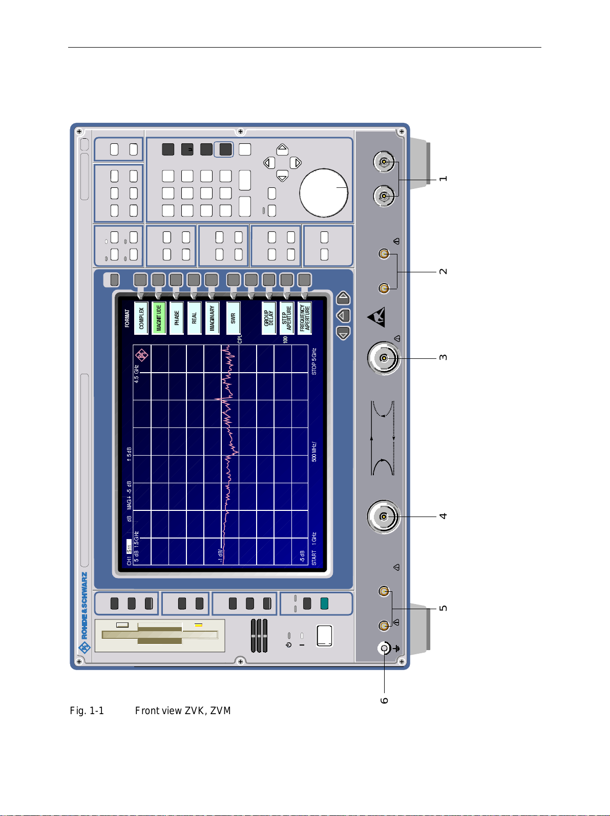
Front View ZVx
MADE IN GERMANY
60
CAL
CAL
OFFSET
n
G
k
M
m
x 1
EXP
ENTER
1127.8500.
RESPONSE
MEAS FORMAT SCALE
DIAGRAM DISPLAY TRACE
CH 1 CH 3
CH 2 CH 4
CHANNEL
USER
7
$
0
5
2
)
]
+
*
%
G
..
VECTOR NETWORK ANALYZER 10 MHz . . . 20 GHz ZVM
%
G
*
$
0
%
G
]
+
*
6
%
G
+
&
9
DATA ENTRYSTIMULUS
;
(
/
3
0
2
&
56
8
7
4
SPAN
START STOP
CENTER
(
'
(
8
7
,
1
*
$
0
/
6
$
$
(
+
5
3
-
.
23
0
1
SWEEP
SWEEP RESTAR T
<
5
$
1
,
*
$
0
,
%
G
12345
b1 b2
CLR BACK
HOLD ST EP
30 V DC MAX
= MKR
SEARCH
MARKER
SOURCE AVG
MARKER
3
5
:
6
/
3
&
<
8
$
/
2
(
5
'
*
LINES
DELTA
3
(
7
6
LINES LIMITS
R2 CHANNEL
<
(
(
&
5
5
1
8
8
(
7
7
8
5
5
4
(
(
(
3
3
5
$
$
)
]
+
*
3
2
7
6
]
+
0
PORT 1 PORT 2 INPUTS
]
+
*
7
%
5
G
$
7
6
+ 20 dBm RF MAX
OUT IN
30 V DC MAX
+ 27 dBm RF MA X
b2
S 12
S 21
S 11 S 22
a1
b1 a2
30 V DC MAX
+ 27 dBm RF MAX
MODE
SYSTEM
INFO
SETUP
COPY
COPY
SETTING
SAVE
MEMORY
CONFIG
RECALL
SRQ
LOCAL
STATUS
PRESET
REM
R1 CHANNEL
30 V DC MAX
+ 20 dBm RF MAX
OUT IN
6
Fig. 1-1 Front view ZVK, ZVM
1043.0009.50 1.12 E-9
Page 88

ZVx Front View
1.2.1.2 Front View ZVK, ZVM
The control elements correspond to those of ZVR with the exception of the connec tors. For this reason,
only the connectors of ZVK and ZVM are described.
1 INPUTS
b1 b2
Additional receiver inputs
(N-sockets b1 and b2)
2 R2 CHANNEL
OUT IN
Accessibility to the reference channel of measurement
port 2.
3PORT 2
PORT 2
Measurement port 2 See chapter 2.14.1 and
4PORT 1
PORT 1
Measurement port 1 See chapter 2.14.1 and
See chapter 2.4.1.2
Ext. Measurements
and Appendix A
2.15.2
2.15.2
5 R1 CHANNEL
OUT IN
Accessibility to the reference channel of measurement
port 1.
6
Ground connector.
1043.0009.50 1.13 E-9
Page 89

Rear View ZVx
36
625
SCPI
IEC BUS
IEC SYSTEM BUS
37
PC MONITOR
38
MULTIP ORT
FOR COMPUTER FC T.
ETHERNET
625
394041424344
LEVEL
USER
COM 1
COM 2 LPT
DC 2
EXT TRIG G E R
REF OUT
29 30 3132 33 34 35 28
27 28
DC MEAS INPUTS
TRIGGER
BLANK
EXTERNAL GENERATOR
GF
22
AUX
® ®
LISTED
MEASURING EQUI PMENT
SER. 123456/001
a1 EXT IN
FUSES
2
PROBE
LO
REFERENCE CHANNEL PORTS
ANALYZER
FUSES1
PROBE
a1 EXT OUT
MONITOR
DC 1
EX T FRE Q RE FE RE NCE
V
+
250
/
L
PORT BIAS
127 - F 500
IEC
+
MOUSE
KEYBOARD
REF IN
V
250
127
/
FUSE
FUSE
12
L
IEC
F 500
V
250
127
/
L
IEC
F 500
48
47
46
45
Fig. 1-2 Rear View
1043.0009.50 1.14 E-9
Page 90

ZVx Rear View
1.2.2 Rear View ZVR, ZVK and ZVM
27
0
I
28
29 EXTERNAL GENERATOR
EXTERNAL GENERATOR
BLANK
TRIGGER
30 DC MEAS INPUTS
DC MEAS INPUTS
Power switch
Fuse holder
AC supply connector
Power supply fans
Connectors for external generator
control
BLANK (input)
TRIGGER (output)
Inputs for DC-voltage measurement
See chapter 1,
sections 1.3.4
and 1.3.5
See chapter 1,
section 1.3.2.1
See Appendix A
DC1 DC2
31 COM2
COM2
32 COM1
COM1
33 USER
USER
Serial interface 2
(9-contact, female; COM2)
Serial interface 1
(9-contact, female; COM1)
User interface with configurable inputs
and outputs
See chapter 1,
section 1.6
and Appendix A
See chapter 1,
section 1.6
and Appendix A
See Appendix A
1043.0009.50 1.15 E-9
Page 91

Rear View ZVx
36
625
SCPI
IEC BUS
IEC SYSTEM BUS
37
PC MONITOR
38
MULTIP ORT
FOR COMPUTER FC T.
ETHERNET
625
394041424344
LEVEL
USER
COM 1
COM 2 LPT
DC 2
EXT TRIG G E R
REF OUT
29 30 3132 33 34 35 28
27 28
DC MEAS INPUTS
TRIGGER
BLANK
EXTERNAL GENERATOR
GF
22
AUX
® ®
LISTED
MEASURING EQUI PMENT
SER. 123456/001
a1 EXT IN
FUSES
2
PROBE
LO
REFERENCE CHANNEL PORTS
ANALYZER
FUSES1
PROBE
a1 EXT OUT
MONITOR
DC 1
EX T FRE Q RE FE RE NCE
V
+
250
/
L
PORT BIAS
127 - F 500
IEC
+
MOUSE
KEYBOARD
REF IN
V
250
127
/
FUSE
FUSE
12
L
IEC
F 500
V
250
127
/
L
IEC
F 500
48
47
46
45
Fig. 1-2 Rear View
1043.0009.50 1.16 E-9
Page 92

ZVx Rear View
34 LPT
LPT
Parallel interface
(printer interface, Centronics-compatible)
35 IEC1
IEC BUS
IEC/IEEE-bus connector 1 See chapter 1,
36 IEC2
IEC SYSTEM BUS
IEC/IEEE-bus connector 2 See chapter 1,
37 PC MONITOR
PC MONITOR
Connector for external VGA monitor See Appendix A
38
See chapter 1,
section 1.6
and Appendix A
section 1.6
and Appendix A
section 1.6
and Appendix A
Inputs or outputs for options, e.g. ethernet and multiport
adapter (or cover plates for retrofitting digital interfaces)
39 LEVEL
LEVEL
Input for external level control See Appendix A
40 EXT TRIGGER
EXT TRIG GER
Input for external trigger See chapter 2,
41 EXT FREQ REFERENCE
EXT FREQ REFERENCE
REF IN
REF OUT
REF IN: Input for external
reference (1 to 16 MHz)
REF OUT: 10-MHz output
See chapter 1.7
section 2.10.1.4 and
Appendix A
See chapter 2.4.2.2
and Appendix A
1043.0009.50 1.17 E-9
Page 93

Rear View ZVx
36
625
SCPI
IEC BUS
IEC SYSTEM BUS
37
PC MONITOR
38
MULTIP ORT
FOR COMPUTER FC T.
ETHERNET
625
394041424344
LEVEL
USER
COM 1
COM 2 LPT
DC 2
EXT TRIG G E R
REF OUT
29 30 3132 33 34 35 28
27 28
DC MEAS INPUTS
TRIGGER
BLANK
EXTERNAL GENERATOR
GF
22
AUX
® ®
LISTED
MEASURING EQUI PMENT
SER. 123456/001
a1 EXT IN
FUSES
2
PROBE
LO
REFERENCE CHANNEL PORTS
ANALYZER
FUSES1
PROBE
a1 EXT OUT
MONITOR
DC 1
EX T FRE Q RE FE RE NCE
V
+
250
/
L
PORT BIAS
127 - F 500
IEC
+
MOUSE
KEYBOARD
REF IN
V
250
127
/
FUSE
FUSE
12
L
IEC
F 500
V
250
127
/
L
IEC
F 500
48
47
46
45
Fig. 1-2 Rear View
1043.0009.50 1.18 E-9
Page 94

ZVx Rear View
42
1
PORT BIAS
IEC127
F500L/250V
2
FUSE
IEC127
F500L/250V
43
PROBE 1 FUSES
+
IEC 127-F500L/250V
_
PROBE 2 FUSES
+
_
44 EXTERNAL REF MIXER
REFERENCE CHANNEL PORTS
a1 EXT INa1 EXT OUT
LO
Power supply fuses for high-impedance
probes 1 and 2 (supply outputs at the front)
(not for ZVK and ZVM)
DC input for active probes connected to port 1
and 2 and associated fuses (with the use of
an active test set)
Connectors for external mixer
a1 EXT OUT: RF output signal to ext.
Ref. mixer
LO: Must be externally
provided
a1 EXT IN: IF input signal from
ext. Ref. mixer
See Append. A
See Append. A
See chapter
2.4.1.6
and Appendix A
45 KEYBOARD
KEYBOARD
46 MOUSE
MOUSE
47 ANALYZER MONITOR
AN AL YZ ER
MONITOR
48 AUX
AUX
Connector for external keyboard See chapter 1,
section 1.5
and Appendix A
Connector for mouse See chapter 1,
section 1.4
and Appendix A
Connector for external monitor See Append. A
For future extensions
1043.0009.50 1.19 E-9
Page 95

Start-Up ZVx
1.3 Start-Up
Important Note:
Before turning the instrument on, it must be observed that the following conditions
are fulfilled:
• instrument covers are in place and all fasteners are tightened,
• fan openings are free from obstructions,
• signal levels at the input connectors are all within specified maximums,
• signal outputs are correctly connected.and not overloaded.
Non-observance may cause damage to the instrument .
1.3.1 Unpacking the Instrument
After the instrument has been removed from its packaging, please insure that all deliverable items are
present as follows:
• Vector network analyzer (ZVR, ZVRE, ZVRL, ZVC, ZVCE, ZVM or ZVK)
• AC power cable, keyboard, mouse
• Operating manual
Now check the instrument for visible mechanical damage. If damage is present, promptly inform the
delivery firm that delivered the instrument. In case damage is found, retain the c arton and the packing
materials.
Equipment returned or sent in for repair must be packed in the original packing or in packing with
electrostatic protection.
1.3.2 Instrument Setup
1.3.2.1 Stand-alone Operation
The network analyzer is designed for use under general laborator y conditions. The ambient conditions
required at the operational site are as follows:
• The ambient temperature must be in
the range of + 5 ... + 45 °C.
Wrist strap with cord
Building ground
Ground connection
of operational site
Heel strap
Floor mat
• All fan openings mus t be unobstructed
and the air flow at the rear panel and at
the side-panel perforations m ust not be
obstructed. The distance to the wall
should be at least 10 cm.
• The mounting surface should be flat.
• To avoid damage of electronic
components of the DUT and the
analyzer, the operational site must be
protected against electrostatic
discharge.
1043.0009.50 1.20 E-9
Page 96

ZVx Start-Up
1.3.2.2 19" Rack Installation
Important Note:
For rack installation, insure that the air flow at the side-panel
perforations and the air exhaust at the rear panel is not obstructed.
The instrument may be mounted in a 19" rack by using the rack adapter kit ZZA-95 (order number:
396.4911.00). The installation instructions are included in the adapter kit.
1.3.3 EMI Protection Measures
In order to prevent electromagnetic interfer ence (EMI), the instrument may be operated only when all
covers are correctly in place. Only adequately shielded signal and control cables may be used (see
recommended accessories).
1.3.4 Connecting to AC Power
The network analyzer is equipped with an AC voltage selection feature and will automatically set itself
according to the applied AC voltage (range: 90 V to 132 V(AC) and 180 V to 265 V(AC), 47 Hz to
440 Hz). The AC power connector is located on the rear panel (see below).
½ Connect the network analyzer to the AC power source using the AC power cable delivered with the
instrument.
1.3.5 AC Power Line Fuses
The network analyzer is protected by two fuses as specified on the power supply name-plate. The fuses
are located in a removable fuse holder which is located between the AC power switch and the AC power
connector (see below).
AC power switch on the rear panel
.
ON
OFF
I
O
AC Power Sw itch
Fuse Holder
AC Power Connector
Power On/Off
½ Depress the AC Power Switch to the desired position
ON/OFF.
After turn-on (position ON), the instr um ent is in the ready
state (STANDBY) or in operation dependent upon the
position of the ON/STANDBY switch located on the
instrument front panel (see below).
Note:The AC power switch may r emain ON continuously.
Switching to OFF is only required when the i nst ru men t
must be completely removed from the AC power source.
Switching to OFF (position OFF) r emoves all instrum ent
circuitry from the AC power source.
1043.0009.50 1.21 E-9
Page 97

Start-Up ZVx
ON/STANDBY
STBY
ON
switch on the front panel
Caution:
In standby mode, the AC
power voltage is present
within the instrument.
Standby
½ ON/STANDBY switch is not depressed.
The yellow LED (STANDBY) is illuminated. The DC
power supply is supplied with power.
Operation
½ ON/STANDBY is depressed.
The green LED (ON) is illuminated. The instrument is
ready for operation. All modules within the instrument are
supplied with power.
1.3.6 Battery-Powered Memory
The network analyzer is equipped with a battery-powered read/write memory (CMOS-RAM) where
instrument settings are saved at power-of f. After each power-on, the network analyzer is reloaded with
the operational parameters which were active jus t prior to the last power-off (ST ANDBY or AC power
OFF).
A lithium battery is used to supply power to the CMOS-RAM. When the battery is depleted (expec ted lif e
is approx. 5 years), any data stored in CMOS-RAM will be lost. In this case, the factory standard setup is
loaded at turn-on. Changing batteries requires opening of the instrument and is described in the s ervice
manual.
1043.0009.50 1.22 E-9
Page 98

ZVx Controller Function
1.4 Controller Function
Caution:
- The drivers used in the integr ated controller function are adapted to the measur ing
instrument. Only the settings descr ibed below should be resorted to. The existing
driver software should be modified only with the update software released by
Rohde&Schwarz.
- Do not power down during booting. Such a switch-off may lead to corruption of the
hard disk files.
The instrument possesses an integrated Windows-NT controller. The user can switch between the
measurement screen and the controller screen. When an external monitor is connected, the
measurement function and the controller function can be displayed simultaneously (see section
"Connecting an External Monitor"). The controller func tion is automatic ally booted on instrument powerup.
Windows NT operation is described in the supplied manual or in the online help of Windows NT.
Login
Windows NT requires a login window in which the user is ask ed to identif y himself by entering his nam e
and password. An autologin comes as standard in the instrument, ie the login is performed automatically
in the background. The user name used for this is "ins tr ument" and the password is also "instrument" (in
small letters).
To login under another name, call up the logout window in the task bar with START - SHUT DOWN.
Mark the item "Close all pr ograms and log on as a differ ent user?" in the window and click YES while
holding the SHIFT key down until the login window is displayed to enter the user identification. The
password should be entered in the correct syntax including low-case and upper-case characters.
Administrator identification
Some of the installations (eg CD- ROM drive) desc ribed below are possible only under the adm inistr ator
login. This is indicated in the relevant window.
The administrator is an identification prescribed by Windows NT which in particular allows system
settings which are disabled for the standard user.
The password for the administrator is 894129 for the instrument.
After an installation under the administrator identification, the "Servic e Pack X" of W indows NT is to be
re-installed, see section "Installation of Windows NT Software".
On the power-up following an installation under the adm inistrator identification, the NT login window is
displayed (no autologin). The user name "Adm inistrator" is indicated in the window. This entry is to be
replaced by "instrument" and then "instrument" as password entered. An autologin is then possible.
Changeover between measurement screen and controller screen
To call up the controller screen use key combination <ALT><SYSREQ> (US keyboard).
To return to the measur ement screen, activate the window "Rohde & Schwarz ZVR NT Interf ac e" on the
controller.
Logout
The instrument can be switched off (standby mode). Logging out of Windows NT is not necessary.
1043.0009.50 1.23 E-9
Page 99

Controller Function ZVx
Additional Software
The following program packages were successfully tested for their compliance with the measuring
instruments software:
½ ZVR-K9 – software for virtual transformation networks
½ FileShredder – for secure deletion of files from hard disk
½ Symantec Norton AntiVirus – virus protection software
1043.0009.50 1.24 E-9
Page 100

ZVx Connecting a Mouse
1.5 Connecting a Mouse
Caution:
The mouse may only be connected when the instrument is switched off
(STANDBY). Otherwise, correct operation of the mouse and instrument cannot be
guaranteed.
The instrument has the facility to simplify operation by connecting a mouse to the rear-panel PS/2mouse connector (MOUSE) for .
MOUSE
During measurement operation, softkeys, tables and data input fields may also be controlled via the
mouse. For computer function, the mouse has the usual functions.
The control functions f or the mouse during measurem ent operation are described in Chapter 2 in the
section "Mouse Operations". Appendix E c ontains a list in which the sc reen display elements f or mous e
control of the corresponding sof t keys and push buttons of the instrument are described. Appendix A
contains the interface description.
After connection the mouse is automatically recognized. Special settings suc h as mouse cursor speed
etc., can be performed in the Windows NT menu START - SETTINGS - CONTROL PANEL - MOUSE.
1.6 Connecting an External Keyboard
Caution:
The keyboard may only be connected when the instrument is switched off
(STANDBY). Otherwise, correct operation of the keyboard cannot be guaranteed.
The instrument is f itted with a rear-panel 5-contact DIN connector (KEYBOARD) for the connec tion of
an external PC keyboard.
KEYBOARD x
During measurement operations , the keyboard simplifies the input of comm entary text, filenames, etc.
For computer function, the keyboard has the usual functions.
Appendix E contains a list which describes the as s ignment of the instrum ent f ront- panel key functions to
the key codes of the external keyboard as well as special k ey combinations used for quick operations.
Appendix A contains the interface description.
After connection the keyboard is autom atically recognized. The default setting is for the US keyboard.
Special settings such as repetitional rate etc. can be performed in Windows NT menu START SETTINGS - CONTROL PANEL - KEYBOARD.
1043.0009.50 1.25 E-9
 Loading...