

Page 1

R&S®TLx9
For information only!
This manual, dated July 9, 2018 reflects the
technical status as of that date. There may
have been technical changes since that time.
Transmitter System
System Manual
(I6ÀÊ2)
2506506002
Version 03
System Manual
Page 2

This manual describes the following R&S®TLx9 models:
●
R&S®TLx9 (2506.5001.10), 1HU, 15/10/5 W
●
R&S®TLx9 (2506.5001.20), 2HU, 200/100/50/25 W
The software contained in this product uses several valuable open source software packages. For information, see the "Open
Source Acknowledgment"
Rohde & Schwarz would like to thank the open source community for their valuable contribution to embedded computing.
on the user documentation CD-ROM (included in delivery).
© 2018 Rohde & Schwarz GmbH & Co. KG
Mühldorfstr. 15, 81671 München, Germany
Phone: +49 89 41 29 - 0
Fax: +49 89 41 29 12 164
Email: info@rohde-schwarz.com
Internet:
Subject to change – Data without tolerance limits is not binding.
R&S® is a registered trademark of Rohde & Schwarz GmbH & Co. KG.
Trade names are trademarks of the owners.
2506.5060.02 | Version 03 | R&S®TLx9
The following abbreviations are used throughout this manual: R&S®TLx9 is abbreviated as R&S TLx9.
www.rohde-schwarz.com
Page 3

Quality management
Certied Quality System
ISO 9001
and environmental
management
Sehr geehrter Kunde,
Sie haben sich für den Kauf
eines Rohde & Schwarz Produktes entschieden. Sie erhalten
damit ein nach modernsten Fertigungsmethoden hergestelltes
Produkt. Es wurde nach den
Regeln unserer Qualitäts- und
Umweltmanagementsysteme
entwickelt, gefertigt und geprüft.
Rohde & Schwarz ist unter anderem nach den Managementsystemen ISO 9001 und ISO 14001
zertifiziert.
Der Umwelt verpflichtet
❙ Energie-efziente,
RoHS-konforme Produkte
❙ Kontinuierliche
Weiterentwicklung nachhaltiger
Umweltkonzepte
❙ ISO 14001-zertiziertes
Umweltmanagementsystem
Dear customer,
You have decided to buy a
Rohde & Schwarz product. This
product has been manufactured
using the most advanced methods. It was developed, manufactured and tested in compliance
with our quality management
and environmental management systems. Rohde & Schwarz
has been certified, for example, according to the ISO 9001
and ISO 14001 management
systems.
Environmental commitment
❙ Energy-efcient products
❙ Continuous improvement in
environmental sustainability
❙ ISO 14001-certied
environmental management
system
Certied Environmental System
ISO 14001
Cher client,
Vous avez choisi d’acheter un
produit Rohde & Schwarz. Vous
disposez donc d’un produit
fabriqué d’après les méthodes
les plus avancées. Le développement, la fabrication et les
tests de ce produit ont été effectués selon nos systèmes de
management de qualité et de
management environnemental.
La société Rohde & Schwarz a
été homologuée, entre autres,
conformément aux systèmes
de management ISO 9001 et
ISO 14001.
Engagement écologique
❙ Produits à efcience
énergétique
❙ Amélioration continue de la
durabilité environnementale
❙ Système de management
environnemental certié selon
ISO 14001
1171.0200.11 V 05.01
1171020011
Page 4

Page 5

Customer Support
Technical support – where and when you need it
For quick, expert help with any Rohde & Schwarz equipment, contact one of our Customer Support
Centers. A team of highly qualified engineers provides telephone support and will work with you to find a
solution to your query on any aspect of the operation, programming or applications of Rohde & Schwarz
equipment.
Up-to-date information and upgrades
To keep your instrument up-to-date and to be informed about new application notes related to your
instrument, please send an e-mail to the Customer Support Center stating your instrument and your wish.
We will take care that you will get the right information.
Europe, Africa, Middle East
North America
Latin America
Asia/Pacific
China
Phone +49 89 4129 12345
customersupport@rohde-schwarz.com
Phone 1-888-TEST-RSA (1-888-837-8772)
customer.support@rsa.rohde-schwarz.com
Phone +1-410-910-7988
customersupport.la@rohde-schwarz.com
Phone +65 65 13 04 88
customersupport.asia@rohde-schwarz.com
Phone +86-800-810-8228 /
+86-400-650-5896
customersupport.china@rohde-schwarz.com
1171.0200.22-06.00
Page 6

Page 7

Page 8

Page 9

R&S®TLx9
2.3.1.1 AC Power Supply.......................................................................................................... 17
2.3.1.2 Changing Fuses............................................................................................................ 17
Contents
Contents
1 Information about this Manual..............................................................7
2 Safety Instructions.................................................................................9
2.1 Safety Instructions for Transmitter Systems and Equipment...................................9
2.2 General Safety Instructions....................................................................................... 10
2.2.1 Basic Safety Instructions...............................................................................................10
2.3 Special Hazard Information........................................................................................17
2.3.1 Hazards from AC Supply Voltage..................................................................................17
2.3.2 Hazards from High‑Energy Electric Circuits..................................................................17
2.3.3 Hazards from RF Radiation...........................................................................................18
2.3.3.1 Obligation to Instruct Personnel.................................................................................... 18
2.3.3.2 RF Shielding..................................................................................................................18
2.3.3.3 Rules When Operating an Amplifier..............................................................................18
2.3.3.4 Rules When Working on an Open Amplifier..................................................................19
3 Transmitter System R&S TLx9............................................................21
3.1 Design and Function – R&S TLx9..............................................................................21
3.1.1 Rack Design..................................................................................................................22
3.1.2 TLx9 system applications..............................................................................................23
3.1.3 TLx9 redundancy systems............................................................................................ 25
3.1.4 Modules and devices.................................................................................................... 29
3.1.4.1 Overview....................................................................................................................... 29
3.1.4.2 Inside View (1HU)......................................................................................................... 30
3.1.4.3 Replaceable Modules (1HU)......................................................................................... 30
3.1.4.4 Inside View (2HU)......................................................................................................... 32
3.1.4.5 Replaceable Modules (2HU)......................................................................................... 33
3.1.4.6 Option Keys...................................................................................................................34
3.1.4.7 Material Number Assignment........................................................................................35
3.1.4.8 Option Boards............................................................................................................... 36
3.1.4.9 Backplane..................................................................................................................... 36
3.1.4.10 Exciter Board.................................................................................................................37
3System Manual 2506.5060.02 ─ 03
Page 10

R&S®TLx9
3.1.4.11 GapFiller Board............................................................................................................. 38
Contents
3.1.4.12 TSP901 (T
3.1.4.13 TSP901 (Transmitter Status Panel) of 2HU device.......................................................40
3.1.4.14 TDU901 (Transmitter Display Unit)............................................................................... 41
3.1.4.15 Power Amplifier Module................................................................................................ 42
3.1.4.16 Power Supplies............................................................................................................. 43
3.1.4.17 Capacitor Backup Battery............................................................................................. 43
3.1.4.18 IPM2/4 Processor Board............................................................................................... 43
3.1.4.19 ASI Distribution Board...................................................................................................44
3.1.4.20 DVB-T/T2 Receiver....................................................................................................... 45
3.1.4.21 DVB-S/S2 Receiver.......................................................................................................45
3.1.4.22 Mini LAN Switch Board................................................................................................. 46
3.1.4.23 LAN Switch Board......................................................................................................... 47
3.1.4.24 Local LAN2 Board......................................................................................................... 47
3.1.4.25 RF Switch Board........................................................................................................... 48
GapFiller Redundancy 1+1 Antenna Redundancy........................................................48
GapFiller Redundancy in 1+1 Systems with Single Antenna........................................ 48
ransmitter Status Panel) of 1HU device ......................................................39
1+1 RF Switch for 15W Backup TX Systems ...............................................................49
3.1.4.26 GapFiller 1+1 15W Redundancy System with RF Switching........................................ 50
3.1.5 Specifications................................................................................................................ 51
3.1.5.1 General Data.................................................................................................................51
3.1.5.2 Inputs............................................................................................................................ 55
3.1.5.3 Quality........................................................................................................................... 56
3.2 Installation R&S TLx9................................................................................................. 56
3.2.1 Unpacking and Setting Up............................................................................................ 56
3.2.1.1 Equipment Supplied...................................................................................................... 56
3.2.1.2 Unpacking Instrument................................................................................................... 57
3.2.1.3 Setting Up Instrument................................................................................................... 57
3.2.2 Connecting Cables........................................................................................................57
3.2.2.1 Overview of Connectors................................................................................................58
3.2.2.2 Connecting Input Signals.............................................................................................. 60
3.2.2.3 Connecting External Reference Sources...................................................................... 60
3.2.2.4 Connecting Antenna System.........................................................................................61
4System Manual 2506.5060.02 ─ 03
Page 11

R&S®TLx9
3.2.2.5 Preparing RF Carrier Loop............................................................................................61
Contents
3.2.2.6 Connecting User Interface
3.2.2.7 Connecting AC Power Supply.......................................................................................62
3.3 Commissioning R&S TLx9......................................................................................... 62
............................................................................................ 61
Annex.................................................................................................... 63
A R&S TLx9 Interface Description......................................................... 63
A.1 Base unit and Exciter / GapFiller Board Interfaces..................................................63
A.1.1 Overview....................................................................................................................... 63
A.1.2 Description.................................................................................................................... 64
A.2 Option Board Interfaces............................................................................................. 70
A.2.1 LAN Switch....................................................................................................................70
A.2.2 Local LAN2 Board......................................................................................................... 73
A.2.3 DVB-T/T2 RX................................................................................................................ 74
A.2.4 DVB-S/S2 RX................................................................................................................75
A.2.5 1+1 ASI Distribution Board............................................................................................80
A.2.6 RF Switch Board........................................................................................................... 82
5System Manual 2506.5060.02 ─ 03
Page 12

R&S®TLx9
Contents
6System Manual 2506.5060.02 ─ 03
Page 13

R&S®TLx9
Information about this Manual
1 Information about this Manual
This manual is part of the documentation for the R&S TLx9 transmitter family from
Rohde & Schwarz. The individual manuals for the transmitter family have a modular
structure and complement each other
Structure
The system manual, which is the central and overarching part of the overall documentation, describes all the steps involved in installing a transmitter.
Operation of the transmitter system after installation and the steps required to put the
system into operation are described in the Tx9 operating manual.
The TLx9 service manual describes all maintenance, troubleshooting and service tasks
that customers can carry out themselves. At certain points in the transmitter manual,
the reader is referred to the appropriate operating manual or service manual.
Contents
.
The manuals for the transmitter family describe all activities required for installation,
startup, operation, maintenance, troubleshooting and servicing of the transmitter and
its component parts. The appendix contains the interface descriptions and the technical documentation.
Safety
All skilled personnel working with a transmitter or its components have a duty to read
the associated manuals and to follow the safety measures described in the section
"Safety" and given at appropriate points in the manual. It must be ensured that the
transmitter and the individual components of the transmitter are used only for their
intended use. All activities connected with the transmitter or individual transmitter components must be carried out by skilled personnel. If activities require additional skills
and qualifications, this is indicated at the appropriate points in the manual.
Symbols and notation
The "warning triangle" symbol refers the reader to potential hazards. The degree of
danger is indicated by different signal words next to the warning symbol.
Instructions are given in numbered steps. All other formatting options are intended to
improve clarity and are self‑explanatory.
7System Manual 2506.5060.02 ─ 03
Page 14

R&S®TLx9
Information about this Manual
8System Manual 2506.5060.02 ─ 03
Page 15

R&S®TLx9
Safety Instructions
Safety Instructions for Transmitter Systems and Equipment
2 Safety Instructions
2.1 Safety Instructions for Transmitter Systems and Equipment
Compliance with safety regulations
The safety regulations specified in this manual must always be complied with.
The following points require special attention:
●
Only qualified technicians are allowed to install and wire the electrical equipment.
●
National and international safety rules and regulations must be observed when
equipping operating facilities and during the assembly and operation of electrical
systems.
These include, for example:
– Protective measures to prevent accidents
Protection against overvoltage
–
– Isolation of electrical systems
– Grounding of electrical systems
– Physical properties and laying of electrical lines and cables
– Regulations that apply to factories, work areas and special systems
●
When installing transmitter racks, it is important to observe national accident prevention regulations, for example, with regard to:
– Crushing hazard when working beneath suspended loads
– Fall hazards when working on ladders
– Risk of injury when lifting heavy loads
●
Personal protective equipment (PPE) must be used when installation or repair work
is being carried out. Depending on the type of work, it may be necessary to wear
protective clothing such as hard hats, safety gloves, eye protection, etc.
●
Instruments and systems must not be operated unless their cabinets are closed.
Observe the appropriate safety instructions when opening cabinets for maintenance or repair work.
●
Isolate all poles when disconnecting instruments and systems from the AC supply.
In addition, disconnect all external sources of power, i.e. all measuring cables,
extension cables and multipoint connectors (except for special service connectors).
Then wait approx. 5 minutes to ensure that the capacitors in the system are sufficiently discharged.
●
Additional information on liquid‑cooled transmitters: When installing the cooling
system and filling it with coolant (pump and heat exchanger), the applicable regula-
9System Manual 2506.5060.02 ─ 03
Page 16

R&S®TLx9
tions on working with hazardous products (coolant) must be observed; see the section "Material Safety Data Sheets" under "EC Safety Data Sheet – Antifrogen".
2.2 General Safety Instructions
This section contains general safety instructions applying to all products manufactured
or sold by Rohde & Schwarz.
In line with IEC215 or EN60215, transmitter systems and their add‑on equipment must
be operated under the responsibility of qualified technicians only. The minimum
requirements for qualified electricians are also defined in the standard "Safety requirements for radio transmitting equipment".
Compliance with all legal and regulatory requirements is a precondition for operating
radio equipment and systems. The operator and/or the operator's authorized representative is responsible for ensuring compliance with these requirements. They must additionally ensure that the training of the operating personnel satisfies the specific requirements of the respective country
. This includes any periodic training that is necessary.
Safety Instructions
General Safety Instructions
2.2.1 Basic Safety Instructions
It is essential to read and observe the following instructions and safety information.
All plants and locations of the Rohde & Schwarz group of companies make every effort
to keep the safety standards of our products up to date and to offer our customers the
highest possible degree of safety. Our products and the auxiliary equipment that they
require are manufactured and tested in line with the applicable safety standards. Compliance with these standards is continuously monitored by our Quality Assurance
department. The product described here has been manufactured and tested in accordance with the enclosed EC Certificate of Conformity and left the manufacturer's plant in
a condition fully complying with the relevant safety standards. To maintain this condition and to ensure safe operation, you must observe all information, warnings and
instructions provided in this manual. Please do not hesitate to contact the
Rohde & Schwarz group of companies if you have any queries regarding these safety
instructions.
Furthermore, it is your responsibility to use the product in an appropriate manner. This
product is designed for use solely in industrial and laboratory environments or, if
expressly permitted, also in the field and must not be used in any way that may cause
personal injury or property damage. You are responsible if the product is used for any
purpose other than its designated purpose or in disregard of the manufacturer's
instructions. The manufacturer shall not be liable for any consequences resulting from
the product being used for purposes other than those for which it is intended.
The product is used for its designated purpose if it is used in accordance with its product documentation and within its performance limits (see data sheet, documentation
and the following safety instructions). Using the product requires technical skills and a
10System Manual 2506.5060.02 ─ 03
Page 17
R&S®TLx9
Safety Instructions
General Safety Instructions
basic knowledge of English. It must therefore be ensured that only skilled and specialized staff or thoroughly trained personnel with the required skills are allowed to use the
product. If personal protective equipment is required for using Rohde & Schwarz products, this will be indicated at the appropriate place in the product documentation. Keep
the basic safety instructions and the product documentation in a safe place and pass
them on to other users of the product.
Observance of the safety instructions is intended to prevent injury or damage resulting
from hazards of all types. T
fully read and fully understand the following safety instructions prior to and during use
of the product. It is also essential to observe all other safety instructions (e.g. relating
to personnel protection) which are given at appropriate points in the product documentation. In these safety instructions, the term "product" refers to all articles sold and distributed by the Rohde & Schwarz group of companies; these include instruments, systems and all accessory items.
Signal words and their meaning
The following signal words are used in the product documentation to warn of risks and
hazards.
o this end, persons who are to use the product must care-
indicates an immediate high-risk hazard which will result in death or serious injury if it
is not avoided.
indicates a potential medium-risk hazard which can result in death or (serious) injury if
it is not avoided.
indicates a low-risk hazard which could result in minor or moderate injury if it is not
avoided.
indicates possible incorrect operation which could result in damage to the product.
These signal words correspond to the standard definitions for civil applications in the
European Economic Area. Definitions that deviate from the standard definition may
also exist in other economic areas or military applications. It is therefore essential to
make sure that the signal words described here are always used only in connection
with the related product documentation and the related product. The use of signal
11System Manual 2506.5060.02 ─ 03
Page 18

R&S®TLx9
Safety Instructions
General Safety Instructions
words in connection with unrelated products or documentation can result in misinterpretation and in personal injury or material damage.
Operating conditions, operating positions and operating locations
The product may be operated only under the operating conditions, in the operation
positions and at the operating locations specified by the manufacturer, without the product's ventilation being obstructed. If the manufacturer's specifications are not
observed, this can result in electric shock, fire and/or serious personal injury or death.
Applicable local or national safety regulations and rules for the prevention of accidents
must be observed in all work performed.
Unless otherwise specified, the following requirements apply to Rohde & Schwarz
1.
products:
a) Operating position: housing base at bottom
b) IP degree of protection: 2X
c) Degree of fouling: 2
d) Overvoltage category: 2
e) For indoor use only
f) Operation up to 2000 m above sea level
g) Transport up to 4500 m above sea level
h) Tolerance for nominal voltage: ±10 %
i) Tolerance for nominal frequency: ±5 %
2. Do not place the product on surfaces, vehicles, shelves or tables that for reasons
of weight or stability are unsuitable for this purpose. Always follow the manufacturer's installation instructions when installing the product and fastening it to objects or
structures (e.g. walls and shelves). Installing the product in a manner that does not
comply with the product documentation could result in personal injury or even
death.
3. Do not place the product on heat‑generating devices (e.g. radiators or fan heaters).
The ambient temperature must not exceed the maximum temperature specified in
the product documentation or in the data sheet. Product overheating can cause
electric shock, fire and/or serious personal injury or even death.
Electrical safety
If the information on electrical safety is not observed either at all or to the extent necessary, electric shock, fire and/or serious personal injury or even death may occur.
1. Prior to switching on the product, always ensure that the nominal voltage set on the
product matches the nominal voltage of the mains supply. If a different voltage is to
be set, the mains fuse of the product may have to be changed accordingly.
2. In the case of products with degree of protection I with movable power feed line
and connector, operation is permitted only at sockets with protective conductor
contact and connected protective conductor.
12System Manual 2506.5060.02 ─ 03
Page 19

R&S®TLx9
Safety Instructions
General Safety Instructions
3. Intentional interruption of the protective conductor either along the feed line or in
the product itself is not permitted. Doing so can result in the danger of an electric
shock from the product. If extension cables or multipoint connectors are used, they
must be checked on a regular basis to ensure that they are safe to use.
4. If the product does not have a mains switch for disconnecting the product from the
power supply
, the plug attached to the connecting cable must be used as a disconnect device. In such cases, it must be ensured that the power plug is within easy
reach and accessible at all times (length of connecting cable approx. 2 m). Functional switches or electronic switches are not suitable for disconnecting the product
from the power supply. If products without mains switches are integrated in racks or
systems, a disconnect device must be provided at the system level.
5. Never use the product if the power cable is damaged. Check the power cable on a
regular basis to ensure that it is in proper operating condition. Take appropriate
safety measures and lay the power cable carefully to ensure that the cable will not
be damaged and that no one can be hurt by, for example, suffering an electric
shock or tripping over the cable.
6. Operation is only permitted in TN/TT supply networks which are fuse-protected with
max. 16 A (higher fuse ratings should only be used after consultation with the
Rohde & Schwarz group of companies).
7. Do not insert the plug into sockets that are dusty or dirty. Insert the plug firmly and
completely into the socket provided. Disregard of these points can lead to sparks,
fire and/or injury.
8. Do not overload the sockets, extension cables or multipoint connectors as this can
cause fire or electric shocks.
9. For measurements in electric circuits with voltages V
> 30 V, suitable measures
rms
(e.g. appropriate measuring equipment, fusing, current limiting, electrical separation, insulation) must be taken to avoid any hazards.
10. In the case of connections to IT equipment (e.g. PCs or industrial computers), it
must be ensured that such connections satisfy the IEC60950‑1/EN60950‑1 or
IEC61010‑1/EN61010‑1 standards that apply in each case.
11. Unless expressly permitted, never remove the cover or any part of the housing
while the product is in operation. Doing so would expose electrical lines and components and could lead to injuries, fire or damage to the product.
12. If a product is to be permanently installed, the connection between the protective
conductor terminal on site and the product's protective conductor must be made
first before any other connection is made. The product may be installed and connected only by a qualified electrician.
13. For permanently installed equipment without built‑in fuses, circuit breakers or similar protective devices, the supply circuit must be fused in such a way that anyone
who has access to the product, as well as the product itself, is adequately protected from injury or damage.
13System Manual 2506.5060.02 ─ 03
Page 20

R&S®TLx9
Safety Instructions
General Safety Instructions
14. Use suitable overvoltage protection to ensure that no overvoltage (such as that
caused by a bolt of lightning) can reach the product. Otherwise the person operating the product will be exposed to the danger of an electric shock.
15. Do not insert foreign objects into the housing openings. Doing so can cause short
circuits inside the product and/or electric shocks, fire or injuries.
Unless otherwise specified, products are not protected against the penetration of
16.
fluids; see also the section "Operating conditions, operating positions and operating locations", item 1. The instruments must therefore be protected against the
penetration of fluids. Failure to observe this point may result in the user suffering
an electric shock or the product being damaged, which in turn can endanger personnel.
17. Never use the product under conditions in which condensation has formed or can
form in or on the product, e.g. if the product has been moved from a cold to a warm
environment. Penetration by water increases the risk of electric shock.
18. Prior to cleaning the product, disconnect it completely from the power supply
(e.g. mains or battery). Clean instruments using a damp, soft, lint-free paper towel
or cotton cloth. Warm water or a mild cleaner (good results have been achieved
using glass cleaner (Mat. No. 0041.5336.00)) is recommended as a cleaning
agent. If any other cleaning agent is to be used, it must be checked beforehand
whether the cleaning agent is compatible with the surface to be cleaned.
Operation
1. Operating the product requires special training and intense concentration. It must
be ensured that persons who operate the product are fit to do so from a physical,
intellectual and mental viewpoint, otherwise there is a risk of injury or damage. It is
the responsibility of the employer/operator to select suitable personnel for operating the product.
2. Before moving or transporting the product, read and observe the information in the
section "Transport" on page 16.
3. As with all industrially manufactured goods, it is not possible to completely rule out
the use of materials which cause allergies, i.e. "allergens" (e.g. nickel). If, when
using Rohde & Schwarz products, allergic reactions occur (e.g. skin rash, frequent
sneezing, red eyes or respiratory problems), consult a doctor immediately in order
to determine the cause and to prevent health problems.
4. Before mechanically and/or thermally processing or dismantling the product, it is
essential to refer to the section "Disposal" on page 16, item 1.
5. Depending on the function, certain products such as RF radio systems can produce an elevated level of electromagnetic radiation. In order to protect unborn life,
pregnant women must be protected by means of suitable measures. Electromagnetic radiation also poses a risk to persons with pacemakers. The employer/operator is obliged to assess and identify workplaces where there is a particular risk of
exposure to radiation, and to take precautions to prevent potential hazards.
14System Manual 2506.5060.02 ─ 03
Page 21

R&S®TLx9
Safety Instructions
General Safety Instructions
6. In the event of fire, toxic substances (gases, fluids, etc.) can be discharged from
the product and damage the health of personnel. If a fire occurs, appropriate measures must therefore be taken (e.g. breathing masks and protective clothing).
7. If a laser product is integrated in a Rohde & Schwarz product (e.g. CD/DVD drive),
no settings or functions other than those described in the product documentation
should be used in order to prevent injury (e.g. from the laser beam).
Repair and service
The product may be opened only by authorized, specially trained personnel. Before
1.
any work is performed on the product or before the product is opened, it must be
disconnected from the supply voltage, otherwise there is a risk of electric shock.
2. Any adjustments, part replacements, maintenance or repairs may be performed
only by authorized Rohde & Schwarz electricians. Only original parts may be used
for replacing safety-relevant parts (e.g. mains switches, power transformers,
fuses). A safety check must be performed after safety‑relevant parts have been
replaced (visual inspection, protective conductor test, insulation resistance measurement, leaking current measurement, functional test). This ensures that the
product remains safe to use.
Batteries and accumulators/cells
If the instructions regarding batteries and accumulators/cells are not observed either at
all or to the extent necessary, product users may be exposed to the risk of explosions,
fire and/or serious personal injury and even death. Batteries and accumulators with
alkaline electrolytes (e.g. lithium cells) must be handled in line with EN 62133.
1. Cells must not be disassembled, opened or crushed.
2. Cells and batteries must not be exposed to heat or fire. Storage in direct sunlight
must be avoided. Keep cells and batteries clean and dry. Clean soiled terminals
using a dry, clean cloth.
3. Cells and batteries must not be short-circuited. Cells or batteries must not be
stored in a box or in a drawer where they can short‑circuit each other, or where
they can be short‑circuited by other conductive materials. A cell or battery should
only be taken out of its original packaging when it is to be used.
4. Keep cells and batteries out of the reach of children. If a cell or battery has been
swallowed, seek medical assistance immediately.
5. Cells and batteries must not be subjected to severe mechanical jolts or impacts.
6. If a cell develops a leak, the fluid must not come into contact with the skin or eyes.
If contact occurs, wash the affected area with plenty of water and seek medical
assistance.
7. There is a risk of explosion if cells or batteries containing alkaline electrolyte
(e.g. lithium cells) are replaced or charged incorrectly. To ensure that the product
15System Manual 2506.5060.02 ─ 03
Page 22

R&S®TLx9
Safety Instructions
General Safety Instructions
remains safe to use, always replace cells or batteries with the appropriate
Rohde & Schwarz type (see the replacement parts list).
8. Cells and batteries must be recycled and kept separate from residual waste. Accumulators and batteries that contain lead, mercury or cadmium must be disposed of
as hazardous waste. Observe the national regulations regarding waste disposal
and recycling.
ransport
T
1. The product may be extremely heavy. Therefore, the product must be handled with
care. In some cases, the user may require a suitable means of lifting or moving the
product (e.g. with a lift truck) to avoid back or other physical injuries.
2. Handles on the products are designed exclusively to enable personnel to transport
the product. The handles are not to be used for securing the product to or on transport equipment (e.g. cranes, forklift trucks, carts, etc.). It is your responsibility to
ensure that the products are attached securely to or on suitable transport or lifting
equipment. Observe the safety regulations from the manufacturer of the used
transport or lifting equipment in order prevent injury to personnel and damage to
the product.
3. If you use the product in a vehicle, it is the responsibility of the driver to drive the
vehicle in a safe and appropriate manner. The manufacturer shall not accept liability for accidents or collisions. Never use the product in a moving vehicle if there is a
risk that this could distract the vehicle driver. Make sure that the product is adequately secured in order to prevent injury or other damage in the event of an accident.
Disposal
1. If products or their components are processed mechanically and/or thermally
beyond the scope of the operating conditions for which they were intended, hazardous materials (dust containing heavy metals such as lead, beryllium, nickel) can
be released. For this reason, the product may only be disassembled by specially
trained personnel. Improper disassembly may be hazardous to your health.
National waste disposal regulations must be observed.
2. If, when handling the product, hazardous materials or operating fluids are encountered which must be disposed of separately (e.g. coolant or engine oils that have to
be changed at regular intervals), the safety instructions from the manufacturer of
these hazardous materials and operating fluids, and the applicable local disposal
regulations must be observed. Also observe any additional relevant safety instructions in the product documentation. Incorrect disposal of hazardous materials or
operating fluids can result in damage to health and the environment.
16System Manual 2506.5060.02 ─ 03
Page 23

R&S®TLx9
2.3.1 Hazards from AC Supply Voltage
2.3.1.1 AC Power Supply
2.3 Special Hazard Information
All voltages of Urms > 30 V AC or U > 60 V DC must be regarded as constituting a
shock hazard. When working with voltages that constitute a shock hazard, appropriate
measures must be taken to prevent exposure to danger
nents. Work on live parts should only be performed in exceptional cases and only if
special safety precautions are taken.
●
Before connecting the AC power supply, it is important to ensure that the power
supply specifications given for the system or instruments match the nominal specifications for the local power supply network. The power supply circuit must be protected by means of fuses in order to prevent overloads and short circuits.
●
Miniature modules have neutral conductor fuses. As a result, the power supply
may still be connected even after interruption of the circuit by a fuse.
Safety Instructions
Special Hazard Information
. Never work on live compo-
2.3.1.2 Changing Fuses
●
Fuses which are accessible to the operator should only be changed after the
instruments have been disconnected from the power supply. They must always be
replaced with fuses that have the same electrical rating, tripping characteristics and
breaking capacity.
●
Motor protection switches and automatic line fuses in those parts of a transmitter
system that can be accessed by users must be tripped. If their response range is
adjustable, the ex‑factory setting must not be altered. If settings are changed inadvertently, the correct values specified in this documentation must be set.
2.3.2 Hazards from High‑Energy Electric Circuits
The instruments contain low-voltage circuits that can be fed from a voltage source with
an extremely low impedance (e.g. amplifier operating voltage). These circuits carry
dangerously high levels of energy. At Rohde & Schwarz, we treat these circuits in the
same way as circuits with hazardous contact voltages. Normally, these circuits are protected by covers to prevent unintentional contact. The cover has a warning label.
In practice it has been repeatedly shown that short circuits caused by small metallic
tools result in severe burns. For safety reasons, any high‑energy electric circuits in
areas of the equipment that can be accessed by users are concealed by protective
covers.
●
Exercise the same amount of caution for measurements on low‑impedance voltages (e.g. for repair purposes) that you would when performing measurements on
operating voltages which constitute a shock hazard.
17System Manual 2506.5060.02 ─ 03
Page 24

R&S®TLx9
2.3.3 Hazards from RF Radiation
2.3.3.1 Obligation to Instruct Personnel
Safety Instructions
Special Hazard Information
Wear suitable protective gear when necessary.
●
Before opening any equipment or removing a particular cover, turn of
supply and wait 5 minutes to ensure that capacitors have discharged sufficiently.
●
Do not discharge capacitors by short‑circuiting them.
●
The operator must train all personnel in the operation of this transmitter or instrument in line with EN60215 and/or IEC215. It is essential that these regular training
sessions emphasize the dangers related to high frequency that exist at the respective transmitter or instrument. Operating personnel are only authorized to adjust
and operate the equipment after they have completed the respective training sessions and their participation has been documented.
f the power
High‑energy RF circuits inside the transmitter or instrument are routed via conventional
removable RF connectors (e.g. type N). Depending on the output power, the output
ports of the transmitter and instrument are equipped with screw-type or plug-in RF
lines or ducts.
If RF lines or modules carry high power, the connection point or the entire module is
tagged with the general danger warning label (yellow triangle with a black exclamation
mark).
2.3.3.2 RF Shielding
Transmitters and instruments from Rohde & Schwarz are shielded so that even in the
immediate vicinity there is no danger from RF radiation when all RF lines are connected. This applies to statutory provisions in Germany, i.e. the regulation concerning electromagnetic fields:
Limits for electrical and magnetic field strengths of high‑frequency installations are
defined in the 26th ordinance of the German Federal Government's Emission Control
Act of December 16, 1996 (26. BImSchV).
2.3.3.3 Rules When Operating an Amplifier
Disconnecting RF lines that are in operation can result in arcs. These can cause burns
and eye injuries.
●
Operation of the amplifier is only permitted if a main or dummy antenna is connected
●
Never disconnect RF lines when the amplifier is in operation
●
Never open the amplifier or modules when the amplifier is in operation
●
Never operate the amplifier if RF lines are exposed
18System Manual 2506.5060.02 ─ 03
Page 25

R&S®TLx9
2.3.3.4 Rules When Working on an Open Amplifier
Safety Instructions
Special Hazard Information
Operation with RF power is not permitted if the instrument has been opened or covers
have been removed.
19System Manual 2506.5060.02 ─ 03
Page 26

R&S®TLx9
Safety Instructions
Special Hazard Information
20System Manual 2506.5060.02 ─ 03
Page 27

R&S®TLx9
Design and Function – R&S TLx9
3 Transmitter System R&S TLx9
3.1 Design and Function – R&S TLx9
The TV transmitters of the TLx9 transmitter family cover the range between 470 MHz
and 790 MHz (UHF band IV/V) and support the digital standards DVB-T, DVB-T2 and
ISDB-T
standards are not supported.
The TLx9 series follows the concept of one product for all scenarios. The TLx9-platform is able to address the applications digital TV transmitter, digital radio transmitter
for band III and GapFiller for many digital standards.
Regarding firmware and software, the TLx9 will apply the Tx9 platform which allows
having a common software and firmware framework for all transmitter systems being
part of the Tx9 generation.
. With the retransmitter option it is going to support DVB-T/T2 only. Analog TV
(B)
Transmitter System R&S TLx9
Product features:
●
Compliance with the digital modulation standards DVB-T, DVB-T2 (full R&S DVBT2 feature set), ISDB-T
●
Output power level per transmitter 5 W up to 15 W in a 19” x 1 HU housing for UHF
(before Bandpass filter)
●
Output power level per transmitter 25 W up to 200 W in a 19” x 2 HU housing for
UHF (before Bandpass filter)
●
Equipped with adaptive non-linear pre-distortion and automatic linear pre-distortion
●
Fully integrated redundancy components (ASI distribution, LAN switch board) for B
transmitter
●
For standard configurations there is no need to do customer specific adaptations in
the factory
●
State of the art GUI
●
Cooling optimized for rack mounting (front – back)
●
Highly flexible system configuration. One product for any application:
– Transmitter
– Retransmitter
– Ready for GapFiller
●
Optional fully integrated control for redundancy components (N+1, 1+1)
●
Flexible configuration of redundancy systems:
– Configuration as a N+1-system with N ≤ 8
– Operation of redundant (B-)transmitter in mixed configurations, e.g. DVB-T and
DVB-T2
– Support of a Backup TX system (1+1, no external Redundancy Control Board
necessary)
, ATSC and DTMB
(B)
21System Manual 2506.5060.02 ─ 03
Page 28

R&S®TLx9
Transmitter System R&S TLx9
Design and Function – R&S TLx9
●
Common Remote Management over Web-Interface and SNMP
. All transmitters of
one redundancy system are:
– visible over the management interfaces as one system
– able to be controlled, monitored and managed by the operator of the TLx9 as
one system
●
Optionally integrated GPS receiver (fitting variant of the Exciter / GapFiller board)
●
Optionally integrated OCXO to provide hold over mode stability in SFN networks
for 24 h in case GPS or external 1 PPS signal fails (fitting variant of the Exciter /
GapFiller board)
●
For transmitter a transport stream feeding over ASI, IP over Gigabit Ethernet or
satellite receiver is possible
●
DVB-T/T2 receiver for retransmission or monitoring application to be optionally
integrated into the TLx9 system
●
DVB-S/S2 receiver module (with on-board CAM module and BTS recovery functionality) to be optionally integrated into the TLx9 system
3.1.1 Rack Design
The TLx9 is an all-in-one solution which means a complete transmitter system is integrated in a 19” x 1 or 2 HU housing (depending on the type) and minimal depth of maximum 600 mm in the power class of 5 W to 200 W.
Figure 3-1: TLx9 front view (1 HU)
Figure 3-2: TLx9 front view without air filter (2 HU)
22System Manual 2506.5060.02 ─ 03
Page 29

R&S®TLx9
Transmitter System R&S TLx9
Design and Function – R&S TLx9
Figure 3-3: TLx9 front view with air filter (2 HU)
It allows inserting up to two hardware option modules (Re-TX, Sat RX, 1+1 control
option etc.) to adjust the configuration for several different scenarios.
Figure 3-4: TLx9 back view, no options mounted (2 HU)
1 = Option slot A
2 = Option slot B
Figure 3-5: TLx9 back view with mounted option (2 HU)
3.1.2 TLx9 system applications
The logical units are arranged according to the following rules:
23System Manual 2506.5060.02 ─ 03
Page 30

R&S®TLx9
Transmitter System R&S TLx9
Design and Function – R&S TLx9
24System Manual 2506.5060.02 ─ 03
Page 31
R&S®TLx9
3.1.3 TLx9 redundancy systems
Transmitter System R&S TLx9
Design and Function – R&S TLx9
The TLx9 will support a maximum of up to 8 active transmitters in an N+1 system
(8+1). For system configurations (e.g. N+1) no additional external control devices are
necessary. The complete system control is placed inside the reserve B-T
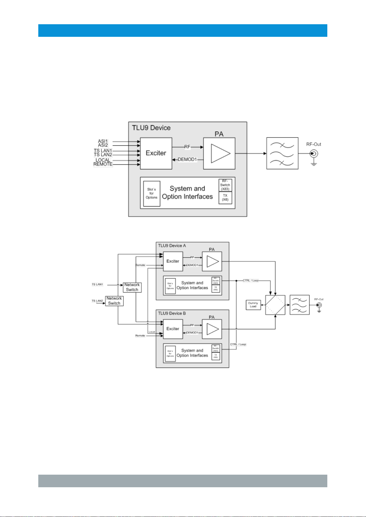
Single TX configuration:
ransmitter.
Backup TX with LAN feeding:
25System Manual 2506.5060.02 ─ 03
Page 32

R&S®TLx9
Transmitter System R&S TLx9
Design and Function – R&S TLx9
Backup TX wit ASI feeding:
26System Manual 2506.5060.02 ─ 03
Page 33

R&S®TLx9
Transmitter System R&S TLx9
Design and Function – R&S TLx9
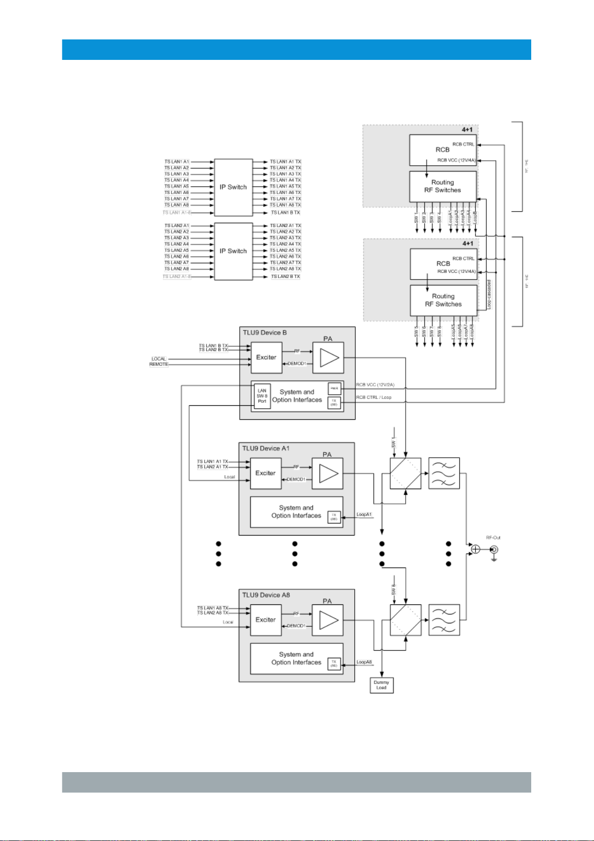
N+1 with ASI feeding (max. 8+1):
27System Manual 2506.5060.02 ─ 03
Page 34
R&S®TLx9
Transmitter System R&S TLx9
Design and Function – R&S TLx9
N+1 with LAN feeding (max. 8+1):
28System Manual 2506.5060.02 ─ 03
Page 35

R&S®TLx9
3.1.4 Modules and devices
3.1.4.1 Overview
Transmitter System R&S TLx9
Design and Function – R&S TLx9
Figure 3-6: Block diagram
29System Manual 2506.5060.02 ─ 03
Page 36

R&S®TLx9
3.1.4.2 Inside View (1HU)
Transmitter System R&S TLx9
Design and Function – R&S TLx9
Figure 3-7: Inside View (1HU)
1 = Exciter / GapFiller board
2 = Backplane
3 = Capacitor backup battery
4 = System power supply
5 = Power Amplifier module
6 = Power Amplifier power supply
7 = Fan E1
8 = Fan E2
9 = Fan E3
3.1.4.3 Replaceable Modules (1HU)
Module Comment
EMI Filter D-SUB 9/15 Pole Filter Circuit Boards
TDK Lambda HWS150A-12 12 V system power supply A4 2506.7604.00
TDK Lambda HWS100A-24/A PSU 108 W power supply A9 3592.0364.00
Capacitor Backup Battery TLx9-B69 A10 2506.8698.02
4GByte Micro SD card for initial installation of TLx9 Exciter /
GapFiller software a device test system (2509.4812.10) is needed
Ref.
des.
Part number
2507.2264.02
2507.3054.00
Chip Card via chip card service kit
1+1 ASI Distribution Board TLx9-B60 (Option slot A/B)
DVB-T / T2 Receiver TLx9-B61 (Option slot A/B)
DVB-S / S2 Receiver TCE900-M10 (Option slot A/B)
1201.5610.23
2506.8600.02
2506.8617.02
2109.3193.02
30System Manual 2506.5060.02 ─ 03
Page 37

R&S®TLx9
Transmitter System R&S TLx9
Design and Function – R&S TLx9
Module Comment
Mini LAN Switch Board TLx9-M6 (Option slot B)
LAN Switch Board TCE900-M6 (Option slot B)
1+1 RF Switch Board TLx9-B59 (Option slot A/B)
PA / System Fan Fan 1 / 2 / 3
12 V 40X40X28 LC
Lithium battery CR 2032
Fuse 10 A F1, F2 0606.3136.00
Mains filter 5/15 W X1 1201.8184.00
Air Filter Mat 1 HU
DX 12 V Ext. Cable Terminal Supply W17 2506.7056.00
X60 RF Cable RF OUT RF output W60 2506.7410.00
X61 RF Cable RF MON RF monitor output W13 2506.7391.00
X66 GPS ANT Cable GPS antenna input W66 2506.7491.00
Insulation Film Insulation film for cover power sup-
ply
Ref.
des.
E1
E2
E3
Part number
2109.2380.03
2109.2897.02
2506.8598.02
3622.9805.00
0858.2049.00
2506.4205.00
2509.4293.00
Cover Power Supply complet Cover with insulation film
2509.4529.00
31System Manual 2506.5060.02 ─ 03
Page 38

R&S®TLx9
3.1.4.4 Inside View (2HU)
Transmitter System R&S TLx9
Design and Function – R&S TLx9
Figure 3-8: Inside View, example 200 W (2HU)
1 = Fan E2
2 = Fan E1
3 = Fan E3
4 = Capacitor backup battery
5 = System power supply
6 = Power Amplifier power supply
7 = Backplane
8 = Power Amplifier module
9 = Exciter / GapFiller board
32System Manual 2506.5060.02 ─ 03
Page 39

R&S®TLx9
3.1.4.5 Replaceable Modules (2HU)
Transmitter System R&S TLx9
Design and Function – R&S TLx9
Module Comment
EMI Filter D-SUB 9/15 Pole Filter Circuit Boards
TDK Lambda HWS150A-12 12 V system power supply A4 2506.7604.00
TSP901 Transmitter Status Panel A5 2507.2935.02
TDK Lambda HFE1600-48 200 W PA related power supply A6 3589.9506.00
TDK Lambda GWS500-36 100
Emerson/Artesyn LCM300Q-T 24 V /
300 W
Capacitor Backup Battery TLx9-B69 A10 2506.8698.02
4GByte Micro SD card for initial installation of TLx9 Exciter /
Chip Card via chip card service kit
1+1 ASI Distribution Board TLx9-B60 (Option slot A/B)
DVB-T / T2 Receiver TLx9-B61 (Option slot A/B)
DVB-S / S2 Receiver TCE900-M10 (Option slot A/B)
Mini LAN Switch Board TLx9-M6 (Option slot A)
W P
A related power supply A8 2506.7804.00
W and 50 W PA related power
25
supply
GappFiller software a device test
system (2509.4812.10) is needed
Ref.
des.
A9
Part number
2507.2264.02
2506.7704.00
2507.3054.00
1201.5610.23
2506.8600.02
2506.8617.02
2109.3193.02
2109.2380.03
LAN Switch Board TCE900-M6 (Option slot A)
1+1 RF Switch Board TLx9-B59 (Option slot A/B)
LAN Local Backup TX TLx9-B58 (Option slot A)
PA Fan Fan 1 (25 W and 50 W) E1 3593.0951.00
PA Fan Fan 1 (100/200 W) E1 3593.0945.00
PA Fan Fan 2 (200 W) E2 3593.0945.00
System Fan Fan 3 (25/50/100/200 W) E3 3593.0945.00
Lithium battery CR 2032
Fuse 10 A F1, F2 0606.3136.00
Mains Filter 25/50/100 W X1 1201.8184.00
Mains Filter 200 W X1 3622.7631.00
Air Filter Mat 2 HU
Fan Sealing Pad
X66 GPS ANT Cable GPS antenna input W66 2506.7210.00
2109.2897.02
2506.8598.02
2506.8581.02
0858.2049.00
2506.6143.00
2506.6243.00
33System Manual 2506.5060.02 ─ 03
Page 40

R&S®TLx9
3.1.4.6 Option Keys
Transmitter System R&S TLx9
Design and Function – R&S TLx9
Option Part number Comment
Service-K0
TLX9-FACTORY
TIME-CONTROL
K00
TLX9-K02 2506.9020.02 Option key SNMP
TLX9-K06 2506.9065.02 Option key DTMB (Transmitter only)
TLX9-K08 2506.9088.02 Option key ISDB-T(B) (Transmitter only)
TLX9-K12 2506.9120.02 Option key DVB-T (Transmitter only)
TLX9-K25 2506.9259.02 Option key DVB-T2 RF MONITORING
TLX9-K31 2506.9313.02 Option key TS OVER IP (Transmitter only)
TLX9-K35 2506.9359.02 Option key MPLP (Transmitter only)
TLX9-K37 2506.9371.02 Option key GPS (Transmitter only)
TLX9-K41 2506.9213.02 Option key ATSC (Transmitter only)
TLX9-K43 2506.9436.02 Option key SIGNAL ANALYSIS (Transmitter only)
TLX9-K44 2506.9442.02 Option key DVB-T2 (Transmitter only)
TLX9-K47 2506.9471.02 Option key DVB-T2 MISO (Transmitter only)
Service Key
TLx9-Factory
Reset time monitoring data
TLx9K0 Demo key
TLX9-K49 2506.9494.02 Option key DVB-T2 LITE (Transmitter only)
TLX9-K50 2506.9507.02 Option key DVB-T2 TONE RESERVATION (Trans-
mitter only)
TLX9-K55 2506.9559.02 Option key DVB-S/S2 RX IP OUTPUT (Transmitter
only)
TLX9-K56 2506.9565.02 Option key DVB-S/S2 RX DECRYPTION (Transmit-
ter only)
TLX9-K59 2506.9594.02 Option key NIT RESTAMPING (Transmitter only)
TLX9-K60 2506.9607.02 Option key BTS DECOMPRESSION (Transmitter
only)
TLX9-K62 2506.9620.02 Option key WINDOW SIZE 14US (GapFiller only)
TLX9-K63 2506.9636.02 Option key WINDOW SIZE 17US (GapFiller only)
TLX9-K64 2506.9642.02 Option key R&S SMART EC (GapFiller only)
TLX9-K65 2506.9659.02 Option key HTML5 GUI
TLX9-K71 2506.9713.02 Option key REDUNDANT FEEDING (Transmitter
only)
TLX9-K73 2506.9736.02 Option key GLONASS (Transmitter only)
TLX9-K74 2506.9742.02 Option key DVB-S/S2 Multistream (Transmitter only)
34System Manual 2506.5060.02 ─ 03
Page 41

R&S®TLx9
3.1.4.7 Material Number Assignment
Transmitter System R&S TLx9
Design and Function – R&S TLx9
Option Part number Comment
TLX9-K80 2506.9807.02 Option key SYSTEM CONTROL
TLX9-K83 2506.9836.02 Option key 10 W
TLX9-K84 2506.9842.02 Option key 15 W
TLX9-K85 2506.9859.02 Option key 50 W
Material No.
of article
2506.5001K02 TLX9 TLx9 System KMAT (Transmitter) 2506.5001.02
2506.5001K03 TLX9-GF TLx9 System KMAT (GapFiller) 2506.5001.02
2506.8023.02 TLX9-B02 Advanced Transmitter Exciter Board 2506.8023.02
2506.8023.02 TLX9-B02 Advanced Transmitter Exciter Board 2507.2229.05
2506.8030.06 TLX9-B03 GapFiller Board 6 MHz 2507.2006.03
2506.8030.08 TLX9-B03 GapFiller Board 8 MHz 2507.2006.02
2506.5001.10 In TLX9 1HE 5/10/15 W Amplifier 2507.2629.02
2506.5001.30 In TLX9-GF
2506.8223.02 TLX9-B22 Air Filter 2 HU *
2506.8423.02 TLX9-B42 25 W Amplifier 2507.2729.02
2506.8430.02 TLX9-B43 50 W Amplifier 2507.2729.02
2506.8446.02 TLX9-B44 100 W Amplifier 2507.2829.02
2506.8452.02 TLX9-B45 200 W Amplifier 2507.2829.02
Name Comment
Keycard 2506.9907.02
5/10/15 W Amplifier 2507.2629.02
1HE
Corresponding Board
Material No. in SW
2109.2380.03 TLX9-M6 Mini LAN Switch, Variant for TLx9 with
mechanical components
2109.2897.02 TCE900-M6 LAN Switch (big version) 2109.2900.02
2506.8581.02 TLX9-B58 Local LAN2 Board Backup TX (only 2HU
devices)
2506.8598.02 TLX9-B59 1+1 RF Switch Board 2507.2135.02
2109.3193.02 TCE900-M10 DVB-S/S2 Receiver (Transmitter only) 5303.7500.02
2506.8600.02 TLX9-B60 1+1 ASI Distribution card 2507.2429.02
2506.8617.02 TLX9-B61 DVB-T/T2 Receiver 2113.9986.02
2506.8698.02 TLX9-B69 Exciter Backup Battery
2506.5101.04
TLX9 CD-ROM Doku
2509.4735.02
No EEPROM
35System Manual 2506.5060.02 ─ 03
Page 42

R&S®TLx9
3.1.4.8 Option Boards
Transmitter System R&S TLx9
Design and Function – R&S TLx9
* The air filter for 1 HU TLU9 is directly installed at the device frame.
The following table shows all possible combinations for the plug‑in of option boards:
Device Option A Option B
DVB-T/T2 RX Yes Yes
DVB-S/S2 RX Yes Yes
ASI Distribution 1+1 Yes Yes
Antenna Switch Yes Yes
LAN Switch (1HU)
LAN Switch (2HU)
*
Wide (200 x 150 mm) and small (200 x 90 mm) options can be mounted.
*
*
No Yes
Yes No
Figure 3-9: Option board positions in 1 HU device
Figure 3-10: Option board positions in 2 HU device
3.1.4.9 Backplane
This module is the base for the inter-board communication.
36System Manual 2506.5060.02 ─ 03
Page 43

R&S®TLx9
3.1.4.10 Exciter Board
Transmitter System R&S TLx9
Design and Function – R&S TLx9
Figure 3-11: Backplane, example 2HU
This board provides the TLx9 Exciter functions, depending on the HW fitting variant:
●
External (customer) interfaces
●
Video input signal handling
●
Channel coding
●
Generation of modulated OFDM signal
●
RF signal generation.
●
Reference and sync input signal handling
●
Regulation of P
●
Digital linear precorrection and non-linear PA precorrection
●
Control of power supplies
●
Control of redundancy switching
●
Different HW fitting variants:
A output power
– Advanced (2 x ASI input, 2 x TSoIP input, GPS and OCXO reference oscillator)
– GapFiller (1 x RF input and OCXO reference oscillator)
●
TCE901 (GPS and OCXO, dual inputs, TS monitoring, local LAN2, measurement
couplers, RF mon, PCIe SW, COFDM out, +13 dBm amp)
37System Manual 2506.5060.02 ─ 03
Page 44

R&S®TLx9
Transmitter System R&S TLx9
Design and Function – R&S TLx9
Figure 3-12: Exciter Board, example type Advanced
3.1.4.11 GapFiller Board
The GapFiller board replaces the Exciter board for GapFiller functions.
The GapFiller is integrated in the x9 transmitter family and supports all commercially
available broadcast standards; such as DVB-T, DVB-T2 (full R&S DVB-T2 feature set),
ISDB-T
, A
TSC and DTMB.
(B)
38System Manual 2506.5060.02 ─ 03
Page 45

R&S®TLx9
Transmitter System R&S TLx9
Design and Function – R&S TLx9
GapFiller Receiver:
●
High performance echo cancellation algorithm: at least -25 dB echo cancellation
gain
●
The echo cancellation settings are automatically adapted to the specific echo situation at the installation site
●
The signal quality at the output is better compared to the R&S XLX8000
Figure 3-13: GapFiller Board
3.1.4.12 TSP901 (Transmitter Status Panel) of 1HU device
The functionality is identical with the TSP901 of the 2HU device (see Chapter 3.1.4.13,
"TSP901 (T
ransmitter Status Panel) of 2HU device", on page 40) but the LEDs and
buttons are arranged in a different way.
39System Manual 2506.5060.02 ─ 03
Page 46

R&S®TLx9
Transmitter System R&S TLx9
Design and Function – R&S TLx9
Figure 3-14: Local operation for 1HU device
3.1.4.13 TSP901 (T
The TSP901 allows local operation of a transmitter and shows basic informations.
Figure 3-15: TSP901 (Transmitter Status Panel)
For N+1 and MultiTX transmitters, each individual transmitter has a separate TSP901,
which allows local operation of the single transmitters.
Meaning of LEDs
LED Message
OK (green) Transmitter, everything OK
Warning (orange)
ransmitter Status Panel) of 2HU device
[1]
Warning for transmitter
Fault (red) Fault for transmitter
Input OK Sum input status of the Exciter / GapFiller is OK
W Sum input status of the Exciter / GapFiller has a Warning
F Sum input status of the Exciter / GapFiller has a
Reference OK Sum reference of the Exciter / GapFiller is OK
W Sum reference of the Exciter / GapFiller has a Warning
F Sum reference of the Exciter / GapFiller has a Fail
Fail
40System Manual 2506.5060.02 ─ 03
Page 47

R&S®TLx9
Transmitter System R&S TLx9
Design and Function – R&S TLx9
Off Reference signal (10 MHz/ PPS/GPS…) is not present and is not
required, since frequency regulation source is set to "Manual"
RF OK Transmitter RF OK
W Transmitter RF W
F
Off Transmitter program off
Local Transmitter Local/Remote
On Transmitter On
[1]
During an update of the FPGA firmware (e.g. after installing a new software version)
T
ransmitter RF Fail
LED shows the Local status (yellow)
(ON/OFF command accepted by the transmitter)
the Warning LED is flashing.
[2]
Special case: Saved RF Fail for (switched over and) switched off transmitter
3.1.4.14 TDU901 (Transmitter Display Unit)
The R&S TDU901 is a display unit with a touchscreen function and a graphical user
interface for configuring Tx9 transmitter systems.
arning
[2]
.
Figure 3-16: TDU901 (Transmitter display unit)
The display has a touchscreen function for operating all of the transmitter functions.
Using sharp‑edged objects can damage or destroy the surface. Therefore only use
your finger to operate the touchscreen.
1. A light touch on a button is enough to trigger a user action.
2. A button lights up orange for as long as your finger remains there. The action is not
carried out until you remove your finger from the button.
41System Manual 2506.5060.02 ─ 03
Page 48

R&S®TLx9
3.1.4.15 Power Amplifier Module
Transmitter System R&S TLx9
Design and Function – R&S TLx9
Tip: To cancel an inadvertently selected action, slide your finger to the side away
from the button highlighted orange and then lift your finger of
f the touchscreen.
The TDU901 Touch-Screen is existing in two variants. The Var. 02 is the standard configuration with mechanical holder and coated front plate. The Var. 03 is extended with a
front LOCAL LAN connection for more convenient LAN cabling (local operation with
Laptop).
If the USB Display Var. 03 is ordered together with a 2HU TLx9 Backup TX System it is
mandatory to order also the option LOCAL LAN2 for the system control device, otherwise the local LAN control at the front is not possible.
The amplifier-pallet operates from 470 MHz to 790 MHz. The whole amplifier stage is
designed as a fixed gain amplifier without any compensation of gain and temperature
and frequency response. There is no internal power or gain control. The entire FPGAbased power control is done on the Exciter / GapFiller board by a variable gain amplifier (VGA) and a voltage variable attenuator (VVA). The detection of the output power
is done on the TLx9 PA module.
Fitting variants:
●
PA Pallet and 200 W heat sink and 2 fans
●
PA Pallet and 100 W heat sink and 1 fan
●
PA Pallet and 50 W heat sink and 1 fan
Figure 3-17: Power Amplifier Module (example)
42System Manual 2506.5060.02 ─ 03
Page 49

R&S®TLx9
3.1.4.16 Power Supplies
Transmitter System R&S TLx9
Design and Function – R&S TLx9
Fitting variants:
●
200 W PA: 12 V PS and 48 V PS and adapter card and EC1
●
100 W PA: 12 V PS and 36 V PS and Euro AC connector
●
50 W PA: 12 V PS and 24 V PS and Euro AC connector
Used Power Supplys:
Voltage Power Material Number Type
12 V 150 W 2506.7604.00 TDK Lambda HWS150A-12
24 V 300 W 2506.7704.00 Emerson LCM300Q-T 24V/300W
36 V 500 W 2506.7804.00 TDK Lambda GWS500-36
48 V 1800 W 3589.9506.00 TDK Lambda HFE1600 - 48
3.1.4.17 Capacitor Backup Battery
Delivers 12 V backup power to the Exciter / GapFiller Board to avoid reboots during
power glitches.
1 AC connector
Figure 3-18: Capacitor Backup Battery
3.1.4.18 IPM2/4 Processor Board
For inter-board and interface controlling.
43System Manual 2506.5060.02 ─ 03
Page 50

R&S®TLx9
3.1.4.19 ASI Distribution Board
Transmitter System R&S TLx9
Design and Function – R&S TLx9
Figure 3-19: IPM2/4 Processor Board
For distribution of ASI inputs between active and reserve TLx9 transmitter
one of the TLx9 option slots for 1+1 or N+1 configuration.
. Installed in
Figure 3-20: ASI Distribution Board
44System Manual 2506.5060.02 ─ 03
Page 51

R&S®TLx9
3.1.4.20 DVB-T/T2 Receiver
Transmitter System R&S TLx9
Design and Function – R&S TLx9
This module is a complete receiver for DVB-T and DVB-T2. Output of the module is a
MPEG transport stream (ASI) and a set of measurement values (RF power, MER,
BER, packet error
,…). The control is done by USB. The receiver can handle the complete VHF and UHF frequency range. To operate the board a reference frequency is
mandatory.
Figure 3-21: DVB-T/T2 Receiver
3.1.4.21 DVB-S/S2 Receiver
This board is using two single tuners and dual demodulator chips. In addition there is
one dual LNB supply and control chip which can control two independent LNBs. There
are two slots available to incorporate CI modules. With this modules the demodulated
transport streams can be encrypted if necessary. The processed transport streams are
connected via the backplane with the Exciter / GapFiller board (for further processing).
It is possible to emit the demodulated and encrypted transport streams via the Ethernet
connector X35 and the ASI out connector X25.
Features:
●
DVB-S; DVB-S2
●
Input frequency range 950 MHz to 2150 MHz
●
Supports 1 to 45 Msymbol/s
●
Continuously variable gain: 0 to 65 dB
●
Programmable 5- to 36-MHz cut-of
●
RF input power for a single carrier: - 80 dBm up to - 10 dBm
f frequency
45System Manual 2506.5060.02 ─ 03
Page 52

R&S®TLx9
Transmitter System R&S TLx9
Design and Function – R&S TLx9
Figure 3-22: DVB-S/S2 Receiver
3.1.4.22 Mini LAN Switch Board
This board is of
●
Connectivity / activity (green LED)
●
Valid Gigabit Ethernet connection (yellow LED)
fering 4 GBit Ethernet ports. T
wo LEDs per interface are for signaling
Figure 3-23: Mini LAN Switch Board
46System Manual 2506.5060.02 ─ 03
Page 53

R&S®TLx9
3.1.4.23 LAN Switch Board
Transmitter System R&S TLx9
Design and Function – R&S TLx9
This board is offering 8 GBit Ethernet ports. T
●
Connectivity / activity (green LED)
●
Valid Gigabit Ethernet connection (yellow LED)
wo LEDs per interface are for signaling
Figure 3-24: LAN Switch Board
3.1.4.24 Local LAN2 Board
The Local LAN2 Board is a passive board to route the Local LAN network connection
from the Exciter / GapFiller Board via the Backplante to the Option Slot A (2 HU housing). This board is only used in 2HU device.
In 1HU devices a second local LAN is accessible at the front of the device. The 2HU
device is missing the second local LAN connection. The board is only used in Backup
TX systems.
47System Manual 2506.5060.02 ─ 03
Page 54
R&S®TLx9
3.1.4.25 RF Switch Board
Transmitter System R&S TLx9
Design and Function – R&S TLx9
Figure 3-25: Local LAN2 Board
This board as a TLx9 option card is to be mounted in the redundancy device (i.e. TX B)
and has no fitting variant in this module.
GapFiller Redundancy 1+1 Antenna Redundancy
The main feature in this configuration is that it supports cross switching between
antenna A to device A or B and antenna B to device A or B
Figure 3-26: GapFiller Redundancy 1+1 Antenna Redundancy
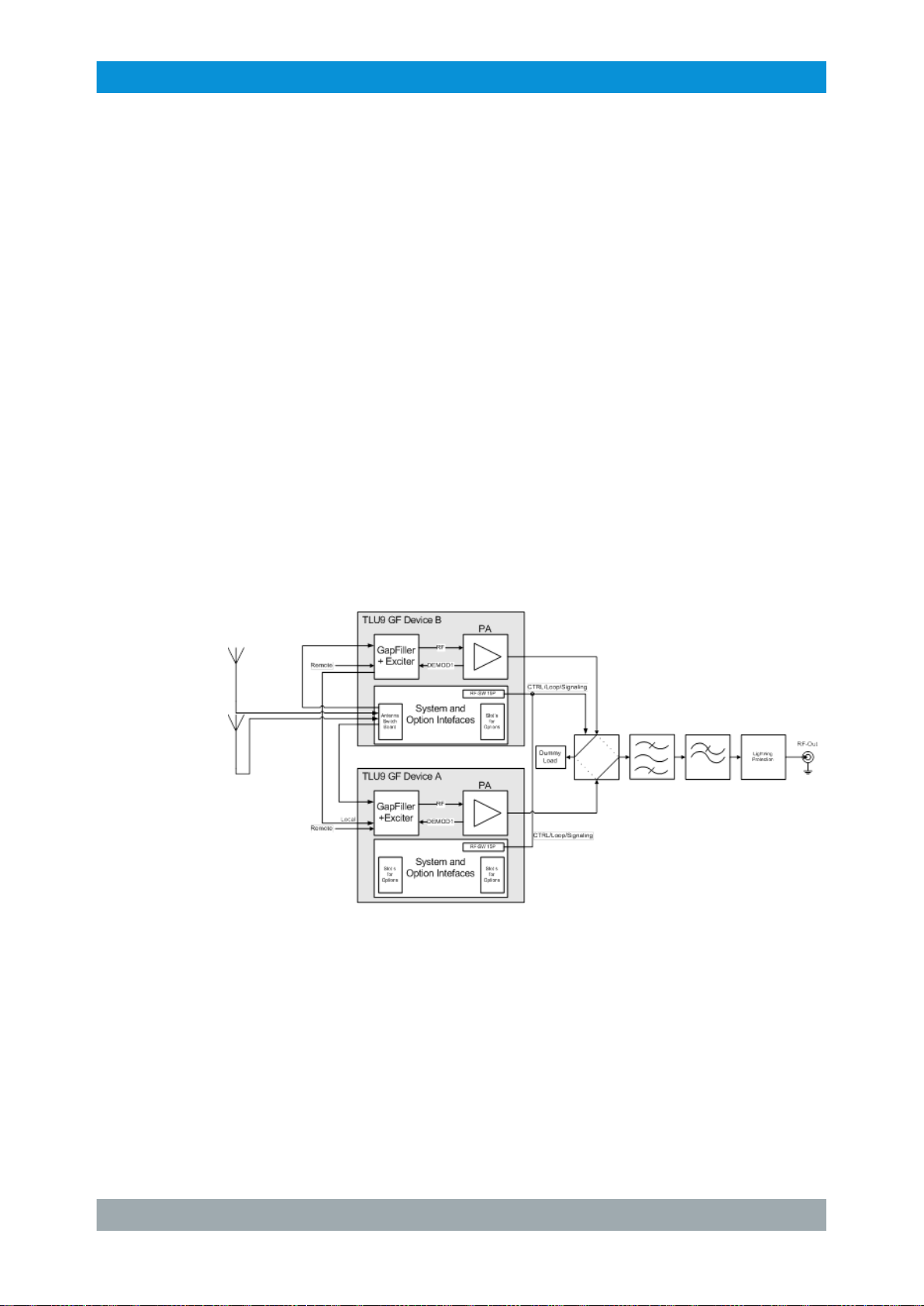
GapFiller Redundancy in 1+1 Systems with Single Antenna
The main feature in this configuration is that switching between device A and B is possible. In normal operation mode, the device B will have no input and hence, no valid
output signal (i.e. passive standby).
48System Manual 2506.5060.02 ─ 03
Page 55

R&S®TLx9
Transmitter System R&S TLx9
Design and Function – R&S TLx9
Figure 3-27: GapFiller Redundancy in 1+1 Systems with Single Antenna
1+1 RF Switch for 15W Backup TX Systems
In this configuration, the optional ASI board is required and has to be mounted in the
redundancy device (i.e. TX B). With the prerequisite fulfilled, the RF Switch board can
be used as a high power (15W OFDM max.) RF switch. In this configuration, the TX B,
in the condition with no TX A connected, must be able to open up the RF loop to avoid
“hot switching”.
Figure 3-28: 1+1 RF Switch for 15W Backup TX Systems
49System Manual 2506.5060.02 ─ 03
Page 56

R&S®TLx9
Transmitter System R&S TLx9
Design and Function – R&S TLx9
Figure 3-29: RF Switch Board
3.1.4.26 GapFiller 1+1 15W Redundancy System with RF Switching
In this configuration, 2 RF switch boards are required and has to be mounted in the
redundancy device (i.e. TX B). With the prerequisite fulfilled, the RF Switch board at
the input can be used to switch an input antenna or to support antenna redundancy
with the second switch board as a high power (15W OFDM max) RF switch. In this
configuration, the TX B, in the condition with no TX A connected, must be able to open
up the RF loop to avoid “hot switching”.
50System Manual 2506.5060.02 ─ 03
Page 57

R&S®TLx9
Transmitter System R&S TLx9
Design and Function – R&S TLx9
Figure 3-30: GapFiller 1+1 15W Redundancy System with RF Switching
3.1.5 Specifications
3.1.5.1 General Data
Frequency range UHF band IV/V (step size 1 Hz): 470 MHz to 790 MHz
Channel bandwidth 6, 7, or 8 MHz 5, 6, 7, 8 or 10
Standards ETSI EN 300 744 ETSI EN 302 755 ARIB STD-B31 (ISDB-T)
SFN / DTx Funktion ETSI TS 101 191 ARIB STD-B31 (ISDB-T)
EMC ETSI EN 302 296/ 302 297 Rec.
DTV average Power 5 to 200 W (before bandpass filter)
RF output power stability
DVB-T DVB-T2 ISDB-T
6, 7 or 8 MHz
MHz
ABNT NBR 15601 (ISDB-T)
ABNT NBR 15601 (ISDB-TB)
ETSI EN 302 296/ 302 297 Rec. 1999/519/EC
1999/519/EC
ETSI EN 301 489-1 / -14
± 0.253 dB ( ± 6 %)
ETSI EN 301 489-1 / -14
(B)
Directivity for VSWR
measurement
MER with predistortion ≥ 34 dB
Shoulder distance with
predistortion
typical 25 to 30 dB
≥ 37 dB
51System Manual 2506.5060.02 ─ 03
Page 58

R&S®TLx9
Transmitter System R&S TLx9
Design and Function – R&S TLx9
Harmonic distance 470 to 530 MHz: ≤ 33 dBc
Flatness with predistortion
VSWR at RF Output ≤ 1.65
Spurious emissions Non harmonics, > 10 kHz of
Frequency Carrier Offset
10 Hz -65 dBc/Hz (OCXO), -50 dBc/Hz typical (TCXO)
100 Hz -85 dBc/Hz
1 kHz -100 dBc/Hz
20 kHz -105 dBc/Hz
DVB-T DVB-T2 ISDB-T
530 to 790 MHz: ≤ 50 dBc
≤ 0.5 dB
(for VSWR ≥ 1.65 the TLx9 will reduce output power)
(for VSWR ≥ 2 the TLx9 will be muted)
fset from carrier with max. gain, sin signal:
≥
50 dBc
Phase noise
(B)
100 kHz -113 dBc/Hz
1 MHz -130 dBc/Hz
OCXO variant (average value after 10 days of operation)
Aging (after 24 hours
operation)
Aging (after 30 days
operation)
Long term aging
Heat up time 10 minutes
TCXO variant ±1 ppm/year
Aging
-9
< 1·10
-8
< 2·10
< 1·10-7/year (0.1 ppm/year)
Redundancy
Backup TX (1+1) and N+1 redundancy
Operation conditions For indoor use only
Environmental conditions
52System Manual 2506.5060.02 ─ 03
Page 59

R&S®TLx9
Transmitter System R&S TLx9
Design and Function – R&S TLx9
Cooling system Air-cooled
Max. installation altitude
Operating temperature +1 °C to +45 °C (Technical data guaranteed)
Permissible temperature
Maximum relative
humidity
Dust conditions Pollution degree 2 (IEC 60664-1)
Air Filter Compliant with DIN EN 779 G2
Environmental class ETSI EN 300-019-1-3
Immunity to radiated
interference
DVB-T DVB-T2 ISDB-T
2000 m (above sea level)
0 °C to +50 °C (Technical data not guaranteed
95 % non-condensing
(with air filter: pollution degree 3)
, in acc. with 3.2, with limited temperature range, non-condensing
Interior
Up to 10 V/m
Power supply
(B)
V
oltage supply 100 to 240 V AC ± 10 %
AC supply frequency 50 Hz to 60 Hz ± 10 %, single phase
Power consumption
To fast transients and
burst in line with IEC
61000-4-4
To surges in line with
IEC 61000-4-5
200 W DTV average power: ~800 W
100 W DTV average power: ~465 W
50 W DTV average power: ~260 W
25 W DTV average power: ~180 W
15 W DTV average power: ~150 W
10 W DTV average power: ~135 W
5 W DTV average power: ~120 W
Immunity
±2 kV (AC mains)
±1 kV (signal inputs)
Symmetrical ±1 kV (e. g. L-N)
Asymmetrical ±2 kV (e. g. L-PE, N-PE)
Mechanical resistance
53System Manual 2506.5060.02 ─ 03
Page 60

R&S®TLx9
Transmitter System R&S TLx9
Design and Function – R&S TLx9
Vibration (sinusoidal) 5 Hz to 150 Hz, max. 1.8 g at 55 Hz, max. 0.5 g from 55 Hz to 150 Hz
Vibration (random) 8 Hz to 500 Hz, acceleration 1.2 g (rms)
Shock Shock response spectrum ramp up 6 dB/octave up to 45 Hz; 45 to 2000 Hz, max. 40 g
ETSI EN 60215 Safety requirements for radio transmission equipment (VDE0866 / IEC 215)
ETSI EN 60950 Safety of information technology equipment incl. electrical business equipment (VDE0805 / IEC 950)
Transport Signal
Inputs
Reference Signal
Inputs
Monitoring and control
interfaces
DVB-T DVB-T2 ISDB-T
Meets DIN EN 60068-2-6
Meets DIN EN 60068-2-64
Meets MIL-STD-810E
Safety standards
Interfaces
1 (2) x ASI (75 Ω), 1 (2) x TSoIP (Ethernet)
GPS antenna in (SMA, 50 Ω), 1 pps and 10 MHz (BNC, 50 Ω)
2 x Ethernet (Local and Remote)
(B)
RF output SMA, 50 Ω, for 5/10/15 W
N, 50 Ω, for 25/50/100/200 W
TS Monitor output BNC, 75 Ω
RF Monitor output SMA, 50 Ω
Reference Monitor
output
eight 5/10/15 W: ~7 kg
W
BNC, 50 Ω
Dimensions and weight
19", 1 HU, Depth 600 mm, for 5/10/15 W
19", 2 HU, Depth 450 mm, for 25/50/100/200 W
(with integrated GPS-receiver
switch, Capacitor pack)
25/50 W: ~10 kg
100W: ~12.05 kg
200W: ~13.85 kg
, 1+1 redundancy components, DVB-S/S2 RX, DVB-T/T2 RX, Ethernet
54System Manual 2506.5060.02 ─ 03
Page 61

R&S®TLx9
3.1.5.2 Inputs
Transmitter System R&S TLx9
Design and Function – R&S TLx9
Input signals ASI
Data rate 3 Mbps to 30 Mbps 3 Mbps to 50 Mbps 32.507937 Mbps
Data inputs 2 x ASI
Data inputs IP 2 x GigaBit Ethernet; RJ-45
Modulator interface - - - T2-MI
Reference frequency 10 MHz; 0.1 to 5 Vpp or TTL, BNC 50 Ω
Reference pulse 1 pps, TTL, BNC 50 Ω
Monitoring Current data rate, input signal present, TS synchronization present
Packet length 204 byte / 188 byte Fixed packet length 188 byte
DVB-T DVB-T2 ISDB-T
TS over IP
BNC 75 Ω
ASI
TS over IP
2 x ASI
BNC 75 Ω
ETSI TS 102773
Generic cont. stream > 64
kbit
Generic fixed packetized
streams < 64 kbit
Generic encapsulated
streams (TS 102606) + high
ficiency mode
ef
ASI
TS over IP
2 x ASI
BNC 75 Ω
- - -
204 byte / 188 byte
(B)
Modulation modes QPSK,
16QAM,
64QAM
FFT modes
(bandwidth specifications for
8 MHz channel)
Extended carrier mode - - - 8K, 16K, 32K
Symbol period 224 μs (2K)
Guard interval 1/4, 1/8, 1/16, 1/32 1/4, 1/8, 1/16, 1/32, 19/128,
Code rate 1/2, 2/3, 3/4, 5/6, 7/8 1/2, 3/5, 2/3, 3/4, 4/5, 5/6 1/2, 2/3, 3/4, 5/6 ,7/8
Trellis coding - - - - - - - - -
2K, 8K
opt. 4K for DVB-H
bandwidth 7.61 MHz
448 μs (4K)
896 μs (8K)
QPSK,
16QAM,
64QAM,
256QAM
1K, 2K, 4K, 8K, 16K, 32K
bandwidth 7.61 MHz
bandwidth 7.77 MHz
112 μs (1K)
224 μs (2K)
448 μs (4K)
896 μs (8K)
1792 μs (16K)
3584 μs (32K)
19/256, 1/128
DQPSK
QPSK
16QAM
64QAM
Mode 1: 2K
Mode 2: 4K
Mode 3: 8K
- - -
252 μs (2K)
504 μs (4K)
1008 µs (8K)
1/4, 1/8, 1/16, 1/32
55System Manual 2506.5060.02 ─ 03
Page 62

R&S®TLx9
Transmitter System R&S TLx9
Installation R&S TLx9
Hierarchical coding included - - - - - -
PAPR - - - yes - - -
Rot. constellation - - - yes - - -
DVB-T2 modes - - - single PLP
Delay correction max. 1000 ms, automatic or manual setting
Precorrection Adaptive digital equalization
DVB-T DVB-T2 ISDB-T
- - -
multi PLP
(ADE)
Adaptive digital equalization
(ADE)
Adaptive digital equalization (ADE)
3.1.5.3 Quality
MER ≥ 33 dB at P
Frequency response before
bandpass filter
Intermodulation suppression ≤ 37 dB ±12 MHz
DVB-T DVB-T2 ISDB-T
nom
< ±0.5 dB < ±0.5 dB < ±0.5 dB
BW 8 MHz at ±4.2 MHz
BW 7 MHz at ±3.7 MHz
BW 6 MHz at ±3.2 MHz
≥ 33 dB at P
≤ 37 dB ±12 MHz
BW 8 MHz at ±4.2 MHz
BW 7 MHz at ±3.7 MHz
BW 6 MHz at ±3.2 MHz
nom
≥ 33 dB at P
≤ 37 dB ±12 MHz
BW 6 MHz at ±3.15 MHz
(B)
(B)
nom
Spectrum mask in line with ETSI EN 302 296
with channel bandpass filter
Spurious emissions ≤ -50 dBc
without channel bandpass filter
Harmonics 470 to 530 MHz: ≤ 33 dBc
530 to 790 MHz: ≤ 50 dBc
without channel bandpass and external harmonic filter
3.2 Installation R&S TLx9
3.2.1 Unpacking and Setting Up
3.2.1.1 Equipment Supplied
ABNT STD-B31 (ISDB-T)
ABNT NBR 15601
Part 1 (ISDB-T
bandpass
) with channel
(B)
The following items are supplied as standard:
56System Manual 2506.5060.02 ─ 03
Page 63

R&S®TLx9
3.2.1.2 Unpacking Instrument
3.2.1.3 Setting Up Instrument
Transmitter System R&S TLx9
Installation R&S TLx9
●
R&S TLx9 all-in-one transmitter system, integrated in a 19” x 1 or 2 HU housing
(depending on the type)
●
Short-circuit connector for X6
●
Power cable (type depending on the target country)
●
User documentation
●
Delivery notes
Carefully remove the instrument from the carton and check the delivery for completeness against the delivery note.
The instrument can be built into a 19“ rack. Depending on the transmitter type, 1 or 2
height units are required for installation.
Make sure the transmitter is firmly fixed in the rack and there is sufficient ventilation.
Make sure in particular that the flow of air through the inlets and outlets is not obstructed.
3.2.2 Connecting Cables
Always make sure that the power supply is disconnected before connecting any devices. This will prevent injuries and damage to the devices.
The cables used to provide ASI, 10 MHz, PPS and GPS signals should be double
shielded.
IP and Ethernet connections should use double shielded class CAT6 cables.
The optional R&S TDU900/901 display unit is connected to the USB Interface, using
an USB 2.0 cable provided by Rohde & Schwarz. Any other cables are not allowed.
The RF cable for the optional satellite receiver should have a minimum screening
attenuation of 1
10 dB.
57System Manual 2506.5060.02 ─ 03
Page 64

R&S®TLx9
3.2.2.1 Overview of Connectors
Transmitter System R&S TLx9
Installation R&S TLx9
Please refer to the system circuit diagram for the system wiring applicable to your system.
Dependig on the transmitter type, maybe not all of the shown connectors are available.
Figure 3-31: Connectors on rear panel of R&S TLx9 (left side)
Figure 3-32: Connectors on rear panel of R&S TLx9 (mid)
Figure 3-33: Connectors on rear panel of R&S TLx9 (right side)
58System Manual 2506.5060.02 ─ 03
Page 65

R&S®TLx9
Transmitter System R&S TLx9
Installation R&S TLx9
Figure 3-34: RF output and RF monitor connectors on rear panel of R&S TLx9
Figure 3-35: Terminal supply and Mains connectors on rear panel of R&S TLx9
Signal
Name/Description
MAINS X1 Power supply AC input
LAN REMOTE X2 Remote LAN connection
TX IF X6 TX connector (CAN bus, 12 V external,
LAN LOCAL X7 Local LAN connection
TERMINAL SUPPLY X12 12 V, 1 A for external components (e.g.
USB X14 USB port (for e.g. backup restore configu-
TS1 IN X20 ASI input feeding
TS2 IN X21 ASI input feeding
TS MONITOR OUT X22 Transport stream / ASI monitor output
Connection point Remarks
position detection)
RCB)
ration via USB stick)
59System Manual 2506.5060.02 ─ 03
Page 66

R&S®TLx9
Transmitter System R&S TLx9
Installation R&S TLx9
Signal
Name/Description
1PPS IN X23 1 PPS input
REF MONITOR X24 Reference monitor output (10 MHz or 1
TS LAN1 X30 Transport stream Input feeding
TS LAN2 X31 Transport stream Input feeding
RF_OUT X60 RF output
RF_MON X61 RF monitor output
REF IN X64 10 MHz reference input
GPS ANT X66 GPS antenna input
DEMOD2 X68 RF input for demodulator (linear predistor-
RF Switch X83 Interface to control a mechanical RF
SD-CARD
3.2.2.2 Connecting Input Signals
Connection point Remarks
PPS)
tion)
switch
Slot for SD-Card
Inputs for digital TV
The input signals can be fed in ASI, T2MI (DVB-T2) or SMPTE format.
●
Connect the first transport stream to X20 (TS 1 IN). With hierarchical coding (DVBT only), X20 is the input for the HP stream
●
If signal standby is required, connect a second transport stream to X21 (TS 2 IN).
With hierarchical coding, X21 is the input for the LP stream
●
Alternatively the input signals can be fed in via IP using X30 (TS LAN1) and X31
(TS LAN2)
3.2.2.3 Connecting External Reference Sources
●
o increase frequency accuracy
T
, connect an external reference source (10 MHz) to
X64 (REF IN)
Alternatively, the second pulse of an external 1 pps signal (at X23) or of the optional
internal GPS receiver (GPS antenna at X66) can be used as the frequency reference
●
For SFN operation, additionally feed a 1 pps signal to allow time synchronization:
If the optional internal GPS receiver is used, connect the GPS antenna to X66
1.
(GPS ANT)
60System Manual 2506.5060.02 ─ 03
Page 67

R&S®TLx9
3.2.2.4 Connecting Antenna System
Transmitter System R&S TLx9
Installation R&S TLx9
2. Alternatively, feed the 1 pps signal of an external reference source via X23 (1PPS
IN)
Risk of RF burns
Before connecting the antenna cable, make sure that the instrument cannot output RF
at the output.
For EMC reasons, only cables with double shielding are to be used at the RF output.
Connect the antenna system to X60 (RF Output).
3.2.2.5 Preparing RF Carrier Loop
Risk of RF burns
Before putting the instrument into operation, make sure that the available interlock loop
systems are in use.
●
Prepare the interlock loop system (if available) for connection to X6 (TX IF)
●
If no interlock loop devices are available in the transmitter system (only permissible
with low power), have the supplied short-circuit connector at the ready
The interlock loop is only closed after (!) startup via X6 (TX IF), after which the instrument can then produce RF
3.2.2.6 Connecting User Interface
For operating the system, it is possible to connect the transmitter to a PC, using an
Ethernet link via RJ-45 connector X7 (LAN LOCAL).
For connection to a remote monitoring network use RJ-45 connector X2 (LAN
REMOTE).
61System Manual 2506.5060.02 ─ 03
Page 68

R&S®TLx9
3.2.2.7 Connecting AC Power Supply
Transmitter System R&S TLx9
Commissioning R&S TLx9
Rohde & Schwarz recommends the use of an double shielded RJ-45 cable which complies with the CAT 6 specification
The instrument can be damaged by overvoltage. Make sure that the AC supply voltage
provided by your local power supply network complies with the specifications of the
power supply unit installed in your instrument.
Risk of electric shock
Check the power cable for damage.
Risk of fire
Make sure that the power cable has the appropriate current carrying capacity necessary for power consumption over the entire temperature range.
●
Set the power switch on the rear of the instrument to 0 (OFF)
●
Connect the instrument to the power supply using the power cable
3.3 Commissioning R&S TLx9
Commissioning and operation of the transmitter system is described in the following
document. R&S® T
ransmitter System Tx9 Operating Manual Mat. No. 2109.91
10.02
62System Manual 2506.5060.02 ─ 03
Page 69

R&S®TLx9
A.1.1 Overview
R&S TLx9 Interface Description
Base unit and Exciter / GapFiller Board Interfaces
Annex
A R&S TLx9 Interface Description
A.1 Base unit and Exciter / GapFiller Board Interfaces
Signal
Name/Description
MAINS X1 Power supply AC input
LAN REMOTE X2 Remote LAN connection
LAN LOCAL X3 Front LAN local for 1HU or for 2HU with
TX X6 TX connector (CAN bus, 12 V external,
LAN LOCAL X7 Local LAN connection
TERMINAL SUPPLY X12 12 V, 1 A for external components (e.g.
USB X14 USB port (for e.g. backup restore configu-
TS1 IN X20 ASI input feeding
TS2 IN X21 ASI input feeding
TS MONITOR OUT X22 Transport stream / ASI monitor output
1PPS IN X23 1 PPS input
REF MONITOR X24 Reference monitor output (10 MHz or 1
Connection point Remarks
option card
position detection)
RCB)
ration via USB stick)
PPS)
TS LAN1 X30 Transport stream Input feeding
TS LAN2 X31 Transport stream Input feeding
RF_OUT X60 RF output
RF_MON X61 RF monitor output
REF IN X64 10 MHz reference input
GPS ANT X66 GPS antenna input
DEMOD2 X68 RF input for demodulator (linear predistor-
tion)
63System Manual 2506.5060.02 ─ 03
Page 70

R&S®TLx9
R&S TLx9 Interface Description
Base unit and Exciter / GapFiller Board Interfaces
Signal
Name/Description
RECEIVER X70 Receiver input for Exciter / GapFiller
RF Switch X83 Interface to control a mechanical RF
A.1.2 Description
Table A-1: X1 - Mains
Signal Name/Description Direction Value range Connection
L1 Input 100 to 240 V AC ± 10 % X1.L Mains connection
N Input 0 V X1.N Mains connection
PE Input 0 V X1.PE Mains connection
IEC (standard with integrated fuses 10 A) for RF output power ≤ 100W OFDM.
EC11 (high current up to 16 A, no integrated fuse) for RF output power 200 W OFDM.
Connection point Remarks
Board
switch
Remarks
point
T
able A-2: X2 - LAN Remote: 8-pin RJ-45 socket
Signal
Direction Value range Connection
Name/Description
BI_DA+ Bidirec-
V
tional
BI_DA- Bidirec-
V
tional
BI_DB+ Bidirec-
V
tional
BI_DB- Bidirec-
V
tional
BI_DC+ Bidirec-
V
tional
BI_DC- Bidirec-
V
tional
BI_DD+ Bidirec-
V
tional
BI_DD- Bidirec-
V
tional
= 670 to 820 mV
odif
f
= 750 mVss typ.
idiff
= 670 to 820 mV
odiff
= 750 mVss typ. X2.4
idiff
= 670 to 820 mV
odiff
= 750 mVss typ. X2.6
idiff
= 670 to 820 mV
odiff
= 750 mVss typ. X2.8
idiff
ss
ss
ss
ss
point
X2.1
X2.2
X2.3
X2.5
X2.7
Remarks
64System Manual 2506.5060.02 ─ 03
Page 71

R&S®TLx9
R&S TLx9 Interface Description
Base unit and Exciter / GapFiller Board Interfaces
Table A-3: X6 - TX: 9-pin Sub-D socket
Signal
Direction Value range Connection
Name/Description
SORT1 / Position1 Bidirec-
0 to + 8,9 V ± 10 % X6.1
tional
CAN_L Bidirec-
CAN-Level X6.2
tional
GND Bidirec-
0 V X6.3
tional
LOOP- Bidirec-
tional
Open: protection loop open
connection to LOOP+ : protection loop closed
SORT2 / Position2 Bidirec-
0 to + 8,9 V ± 10 % X6.5
tional
/AC_FAIL Input 0 to + 11,2 V
Input Pullup: 5 kΩ
Input Pulldown: 136 kΩ
Idle Level: 1
CAN_H Bidirec-
CAN-Level X6.7
tional
LOOP+ Bidirec-
tional
Open: protection loop open
connection to LOOP+ : protection loop closed
1,2 V
± 5 %
Remarks
point
X6.4
X6.6 Externally pulled
down to GND by
resistor > 5 k Ω
resp. ≤ 100 Ω
X6.8
+12V_RC Output + 12 V ± 1,5 % X6.9 Supply for system
components
Table A-4: X7 - LAN Local: 8-pin RJ-45 socket
Signal
Name/Description
BI_DA+ Bidirectional V
BI_DA- Bidirectional
BI_DB+ Bidirectional V
BI_DB- Bidirectional
BI_DC+ Bidirectional V
BI_DC- Bidirectional
BI_DD+ Bidirectional V
BI_DD- Bidirectional
Direction Value range Connection
point
= 670 to 820 mV
odiff
= 750 mVss typ.
V
f
idif
= 670 to 820 mV
odiff
= 750 mVss typ.
V
f
idif
= 670 to 820 mV
odiff
= 750 mVss
V
f
idif
= 670 to 820 mV
f
odif
V
= 750 mVss typ.
idiff
typ. X7.6
X7.1
ss
X7.2
X7.3
ss
X7.4
X7.5
ss
X7.7
ss
X7.8
Remarks
65System Manual 2506.5060.02 ─ 03
Page 72

R&S®TLx9
R&S TLx9 Interface Description
Base unit and Exciter / GapFiller Board Interfaces
Table A-5: X12 - Terminal Supply: 4P connector
Signal Name/Description Direction Value range Connection
point
TERMINAL SUPPLY Output 12 V DC ± 1,5 V X12.1 I
GND Bidirec-
tional
USB SUPPLY Output 5 V DC ± 0,5 V X12.3 I
GND Bidirec-
tional
Table A-6: X14 - USB: USB connector type A
Signal Name/Description Direc-
+5V USB Output
USB Data- Bidirec-
USB Data+ Bidirec-
GND Bidirec-
0 V X12.2
0 V X12.4
Value range Connection
tion
tional
tional
tional
point
X14.1
X14.2
X14.3
X14.2 GND / shield
Remarks
= 1.6 A
max.
= 1 A
max.
Remarks
Direction
tional
Direction
tional
Direction
tional
Ω
Value range Connection
point
0 V X20.2 GND / shield
Ω
Value range Connection
point
0 V X22.2 GND / shield
Ω
Value range Connection
point
0 V X22.2 GND / shield
Table A-7: X20 – TS1 IN: BNC jack 75
Signal
Name/Description
TS1 Input ASI / SMPTE310M X20.1
GND Bidirec-
Table A-8: X21 – TS2 IN: BNC jack 75
Signal
Name/Description
TS2 Input ASI / SMPTE310M X21.1
GND Bidirec-
Table A-9: X22 – TS Monitor: BNC jack 75
Signal
Name/Description
TS_MON Output ASI / SMPTE310M X22.1
GND Bidirec-
Remarks
Remarks
Remarks
66System Manual 2506.5060.02 ─ 03
Page 73

R&S®TLx9
R&S TLx9 Interface Description
Base unit and Exciter / GapFiller Board Interfaces
Direction
Ω
Value range Connection
point
X23.1 Seconds pulse from
Table A-10: X23 – 1PPS IN: BNC jack 50
Signal
Name/Description
1PPS_EXTERN Input 3.3 V-LVTTL or TTL
Ri = 50 Ω for AC pos.
edge
GND Bidirec-
tional
Table A-11: X24 – REF MON: BNC jack 50
Signal
Name/Description
Direction
0 V X23.2 to
X23.5
Ω
Value range Connection
point
REF_MON Output 3.3 V-LVTTL X24.1
GND Bidirec-
0 V X24.2 GND / shield
tional
Table A-12: X30 - TS LAN1: 8-pin RJ-45 socket
Signal
Direction Value range Connection
Name/Description
BI_DA+ Bidirectional V
= 670 to 820 mV
odiff
ss
point
X30.1
Remarks
external GPS
receiver
GND / shield
Remarks
Remarks
BI_DA- Bidirectional
BI_DB+ Bidirectional V
BI_DB- Bidirectional
BI_DC+ Bidirectional V
BI_DC- Bidirectional
BI_DD+ Bidirectional V
BI_DD- Bidirectional
V
idiff
odif
V
idiff
odif
V
idif
odiff
V
idif
Table A-13: X31 - TS LAN2: 8-pin RJ-45 socket
Signal
Direction Value range Connection
Name/Description
BI_DA+ Bidirectional V
BI_DA- Bidirectional
BI_DB+ Bidirectional V
BI_DB- Bidirectional
BI_DC+ Bidirectional V
odiff
V
idif
odiff
V
idif
odiff
= 750 mVss typ.
= 670 to 820 mV
f
= 750 mVss typ.
= 670 to 820 mV
f
= 750 mVss typ.
f
= 670 to 820 mV
= 750 mVss typ.
f
= 670 to 820 mV
= 750 mVss typ.
f
= 670 to 820 mV
= 750 mVss typ.
f
= 670 to 820 mV
X30.2
X30.3
ss
X30.4
X30.5
ss
X30.6
X30.7
ss
X30.8
Remarks
point
X31.1
ss
X31.2
X31.3
ss
X31.4
X31.5
ss
BI_DC- Bidirectional
= 750 mVss typ.
V
f
idif
X31.6
67System Manual 2506.5060.02 ─ 03
Page 74

R&S®TLx9
R&S TLx9 Interface Description
Base unit and Exciter / GapFiller Board Interfaces
Signal
Name/Description
BI_DD+ Bidirectional V
BI_DD- Bidirectional
Table A-14: X60 - RF output: N-connector 50
Signal
Name/Description
RF_OUT Output P
Direction Value range Connection
point
= 670 to 820 mV
f
odif
V
= 750 mVss typ.
idiff
X31.7
ss
X31.8
Ω
Direction Value range Connection
point
= 200 W (DVB-T)
AVG, max.
X60.1
470 MHz to 790 MHz
at 50 Ω load, s ≤ 1.4
GND Bidirectional
Table A-15: X61 – RF Monitor: SMA socket 50
Signal
Direction Value range Connection
Name/Description
X60.2 GND / shield
Ω
point
RF_MON Output -7 dBm ±2 dB X61.1
GND Bidirectional
X61.2 GND / shield
Remarks
Remarks
Remarks
Table A-16: X64 – REF IN: BNC jack 50
Signal
Direction Value range Connection
Name/Description
EXT_REF_IN Input 5 MHz / 10 MHz
Ω
Remarks
point
X64.1
-5.0 dBm to 20 dBm or TTL
GND Bidirectional
Table A-17: X66 – GPS ANT: SMA socket 50
Signal
Direction Value range Connection
Name/Description
GPS ANTENNA Input -144 dBm to -5 dBm X66.1
X64.2 GND / shield
Ω
Remarks
point
GND Bidirectional 0 V X66.2 GND / shield
Table A-18: X68 – DEMOD2: QMA socket 50
Signal
Direction Value range Connection
Name/Description
DEMOD2 Input +7 dBm (-9 / +1 dB) DTV
Ω
160 to 790 MHz
S11 ≤ -16 dB
Remarks
point
X68.1 RF Input for
Demodulator
(linear predistortion)
GND Bidirectional 0 V X68.2 GND / shield
68System Manual 2506.5060.02 ─ 03
Page 75

R&S®TLx9
R&S TLx9 Interface Description
Base unit and Exciter / GapFiller Board Interfaces
Table A-19: X83 - RF SWITCH: 15-pin Sub-D socket
Signal
Name/Description
+12V_RFSW Output +12V ± 20 %
LOOP+ Output Opened Loop:
STATUS_POS1/2_ULI
NK
CONTROL_SWITCH_
POS2
EXT_DOOR_CO
NTACT
Direction
Input 3 states: OPEN / 0 V / 12 V X83.3 ULINK position detec-
Output 0 V to 28 V X83.4 Open collector output:
Input
Value range Connec-
Loading current up to 120 mA
Loop+ to Loop- voltage is 12 V
± 10 %
Closed Loop:
Current is 2.5 mA ± 10 %
2 states: 0 V / 12 V X83.5 Connect to 0V_RFSW:
Remarks
tion point
X83.1 This pin is protected by a
0.14 A PTC@23 °C
X83.2 Loop control output
tion:
OPEN for position open
0 V for position 2
12 V for position 1
1.25 W@25°C maximum
Door closed
Connect to 12V_RFSW:
Door open
COOLING_DL_1 Output
+12V Output +12 V ± 10 %
0V_RFSW Output 0 V X83.8
LOOP- Input Opened Loop:
STATUS_POS1/2_SW
ITCH
CONTROL_SWITCH_
POS1
Input 3 states: OPEN / 0 V / 12 V X83.10 RF Switch position
Output 0 V to 28 V X83.11 Open collector output:
Loading current up to 2 A (100 ms)
Loop+ to Loop- voltage is 12 V
± 10 %
Closed Loop:
Current is 2.5 mA ± 10 %
X83.6 Relay controlled pins to
X83.7 This pin is protected by a
X83.9 Loop control input
open/short dummy load
for antenna cooling
Maximum voltage
applied on these pins is
30 V ± 10 %
1.5 A PTC@20 °C
detection:
OPEN for position open
0 V for position 2
12 V for position 1
1.25 W@25°C maximum
69System Manual 2506.5060.02 ─ 03
Page 76

R&S®TLx9
R&S TLx9 Interface Description
Option Board Interfaces
Signal
Name/Descrip-
Direction
Value range Connec-
tion
OVER_VOLTAGE Input 2 states: 0 V / 12 V X83.12 Connect to 0V_RFSW is
GND Bidirec-
0 V X83.13
tional
COOLING_DL_2 Output Maximum short current is 1 A
± 10 %
EXT_SWITCH-
Input 2 states: 0 V / 12 V X83.15 Connect to 0V_RFSW is
OVER
A.2 Option Board Interfaces
Remarks
tion point
OK
Connect to 12V_RFSW
is Over V
oltage
MAS
X83.14 Relay controlled pins to
open / short dummy load
for antenna cooling
Maximum voltage
applied on these pins is
30 V ± 10 %
Switched Over
Connect to 12V_RFSW
is Not Switched Over.
A.2.1 LAN Switch
Table A-20: X50 - LAN1: 8-pin RJ-45 socket
Signal
Name/Description
BI_DA+ Bidirectional V
BI_DA- Bidirectional
BI_DB+ Bidirectional V
BI_DB- Bidirectional
BI_DC+ Bidirectional V
BI_DC- Bidirectional
BI_DD+ Bidirectional V
BI_DD- Bidirectional
Direction Value range Connection
point
= 670 to 820 mV
f
odif
V
= 750 mVss typ.
idiff
= 670 to 820 mV
f
odif
V
= 750 mVss typ.
idiff
= 670 to 820 mV
f
odif
= 750 mVss typ.
V
f
idif
= 670 to 820 mV
odiff
= 750 mVss typ.
V
f
idif
X50.1
ss
X50.2
X50.3
ss
X50.4
X50.5
ss
X50.6
X50.7
ss
X50.8
Remarks
70System Manual 2506.5060.02 ─ 03
Page 77

R&S®TLx9
R&S TLx9 Interface Description
Option Board Interfaces
Table A-21: X51 - LAN2: 8-pin RJ-45 socket
Signal
Direction Value range Connection
Name/Description
BI_DA+ Bidirectional V
BI_DA- Bidirectional
BI_DB+ Bidirectional V
BI_DB- Bidirectional
BI_DC+ Bidirectional V
BI_DC- Bidirectional
BI_DD+ Bidirectional V
BI_DD- Bidirectional
Table A-22: X52 - LAN3: 8-pin RJ-45 socket
Signal
Direction Value range Connection
Name/Description
BI_DA+ Bidirectional V
BI_DA- Bidirectional
BI_DB+ Bidirectional V
= 670 to 820 mV
f
odif
V
= 750 mVss typ.
idiff
= 670 to 820 mV
f
odif
V
= 750 mVss typ.
idiff
= 670 to 820 mV
f
odif
V
= 750 mVss typ.
idiff
= 670 to 820 mV
f
odif
= 750 mVss typ.
V
f
idif
= 670 to 820 mV
odiff
= 750 mVss typ.
V
f
idif
= 670 to 820 mV
odiff
Remarks
point
X51.1
ss
X51.2
X51.3
ss
X51.4
X51.5
ss
X51.6
X51.7
ss
X51.8
Remarks
point
X52.1
ss
X52.2
X52.3
ss
BI_DB- Bidirectional
BI_DC+ Bidirectional V
BI_DC- Bidirectional
BI_DD+ Bidirectional V
BI_DD- Bidirectional
Table A-23: X53 - LAN4: 8-pin RJ-45 socket
Signal
Direction Value range Connection
Name/Description
BI_DA+ Bidirectional V
BI_DA- Bidirectional
BI_DB+ Bidirectional V
BI_DB- Bidirectional
BI_DC+ Bidirectional V
BI_DC- Bidirectional
BI_DD+ Bidirectional V
= 750 mVss typ.
V
f
idif
= 670 to 820 mV
odiff
= 750 mVss typ.
V
f
idif
= 670 to 820 mV
odiff
= 750 mVss typ.
V
f
idif
= 670 to 820 mV
odiff
V
= 750 mVss typ.
idiff
= 670 to 820 mV
f
odif
V
= 750 mVss typ.
idiff
= 670 to 820 mV
f
odif
V
= 750 mVss typ.
idiff
= 670 to 820 mV
f
odif
X52.4
X52.5
ss
X52.6
X52.7
ss
X52.8
Remarks
point
X53.1
ss
X53.2
X53.3
ss
X53.4
X53.5
ss
X53.6
X53.7
ss
BI_DD- Bidirectional
V
= 750 mVss typ.
idiff
X53.8
71System Manual 2506.5060.02 ─ 03
Page 78

R&S®TLx9
R&S TLx9 Interface Description
Option Board Interfaces
Table A-24: X54 - LAN5: 8-pin RJ-45 socket
Signal
Direction Value range Connection
Name/Description
BI_DA+ Bidirectional V
BI_DA- Bidirectional
BI_DB+ Bidirectional V
BI_DB- Bidirectional
BI_DC+ Bidirectional V
BI_DC- Bidirectional
BI_DD+ Bidirectional V
BI_DD- Bidirectional
Table A-25: X55 - LAN6: 8-pin RJ-45 socket
Signal
Direction Value range Connection
Name/Description
BI_DA+ Bidirectional V
BI_DA- Bidirectional
BI_DB+ Bidirectional V
= 670 to 820 mV
f
odif
V
= 750 mVss typ.
idiff
= 670 to 820 mV
f
odif
V
= 750 mVss typ.
idiff
= 670 to 820 mV
f
odif
V
= 750 mVss typ.
idiff
= 670 to 820 mV
f
odif
= 750 mVss typ.
V
f
idif
= 670 to 820 mV
odiff
= 750 mVss typ.
V
f
idif
= 670 to 820 mV
odiff
Remarks
point
X54.1
ss
X54.2
X54.3
ss
X54.4
X54.5
ss
X54.6
X54.7
ss
X54.8
Remarks
point
X55.1
ss
X55.2
X55.3
ss
BI_DB- Bidirectional
BI_DC+ Bidirectional V
BI_DC- Bidirectional
BI_DD+ Bidirectional V
BI_DD- Bidirectional
Table A-26: X56 - LAN7: 8-pin RJ-45 socket
Signal
Direction Value range Connection
Name/Description
BI_DA+ Bidirectional V
BI_DA- Bidirectional
BI_DB+ Bidirectional V
BI_DB- Bidirectional
BI_DC+ Bidirectional V
BI_DC- Bidirectional
BI_DD+ Bidirectional V
= 750 mVss typ.
V
f
idif
= 670 to 820 mV
odiff
= 750 mVss typ.
V
f
idif
= 670 to 820 mV
odiff
= 750 mVss typ.
V
f
idif
= 670 to 820 mV
odiff
V
= 750 mVss typ.
idiff
= 670 to 820 mV
f
odif
V
= 750 mVss typ.
idiff
= 670 to 820 mV
f
odif
V
= 750 mVss typ.
idiff
= 670 to 820 mV
f
odif
X55.4
X55.5
ss
X55.6
X55.7
ss
X55.8
Remarks
point
X56.1
ss
X56.2
X56.3
ss
X56.4
X56.5
ss
X56.6
X56.7
ss
BI_DD- Bidirectional
V
= 750 mVss typ.
idiff
X56.8
72System Manual 2506.5060.02 ─ 03
Page 79

R&S®TLx9
R&S TLx9 Interface Description
Option Board Interfaces
Table A-27: X57 - LAN8: 8-pin RJ-45 socket
Signal
Name/Description
BI_DA+ Bidirectional V
BI_DA- Bidirectional
BI_DB+ Bidirectional V
BI_DB- Bidirectional
BI_DC+ Bidirectional V
BI_DC- Bidirectional
BI_DD+ Bidirectional V
BI_DD- Bidirectional
A.2.2 Local LAN2 Board
Table A-28: X3 - Network Port: 8-pin RJ-45 socket
Signal
Name/Description
TX+ (D1+) Bidirectional -1 V to +1 V
Direction Value range Connection
point
= 670 to 820 mV
f
odif
V
= 750 mVss typ.
idiff
= 670 to 820 mV
f
odif
V
= 750 mVss typ.
idiff
= 670 to 820 mV
f
odif
V
= 750 mVss typ.
idiff
= 670 to 820 mV
f
odif
= 750 mVss typ.
V
f
idif
X57.1
ss
X57.2
X57.3
ss
X57.4
X57.5
ss
X57.6
X57.7
ss
X57.8
Direction Value range Connection
point
X3.J1
Differential to TX-
Impedance: 100
Ω
Remarks
Remarks
TX- (D1-) Bidirectional -1 V to +1 V
Differential to TX+
Impedance: 100
RX+ (D2+) Bidirectional -1 V to +1 V
Differential to RX-
Impedance: 100
D3+ Bidirectional -1 V to +1 V
Differential to D3-
Impedance: 100
D3- Bidirectional -1 V to +1 V
Dif
ferential to D3+
Impedance: 100
RX- (D2-) Bidirectional -1 V to +1 V
Differential to RX+
Impedance: 100
X3.J2
Ω
X3.J3
Ω
X3.J4
Ω
X3.J5
Ω
X3.J6
Ω
73System Manual 2506.5060.02 ─ 03
Page 80

R&S®TLx9
R&S TLx9 Interface Description
Option Board Interfaces
Signal
Name/Description
D4+ Bidirectional -1 V to +1 V
D4- Bidirectional
A.2.3 DVB-T/T2 RX
Table A-29: X69 – RF IN: BNC jack 50
Signal
Name/Description
RF IN Input 30 MHz to 1 GHz
GND Bidirec-
Direction Value range Connection
point
X3.J7
ferential to D4-
Dif
Impedance: 100 Ω
-1 V to +1 V
Differential to D4+
Impedance: 100 Ω
X3.J8
Ω
Direction
tional
Value range Connection
point
X69.1 RF input
-92 dBm to 0 dBm
75 Ω
0 V X69.2 GND / shield
Remarks
Remarks
Table A-30: X28 – ASI IN: BNC jack 75
Signal
Name/Description
ASI IN Input 270 Mbit/s
GND Bidirec-
Table A-31: X29 – ASI OUT: BNC jack 75
Signal
Name/Description
ASI OUT Output 270 Mbit/s
GND Bidirectional 0 V X29.2 GND / shield
Direction Value range Connection
Direction
tional
Ω
Value range Connection
point
X28.1 ASI input
Uss = 800 mV, 75 Ω
0 V X28.2 GND / shield
Remarks
Ω
Remarks
point
X29.1 ASI output
Uss = 800 mV, 75 Ω
74System Manual 2506.5060.02 ─ 03
Page 81

R&S®TLx9
A.2.4 DVB-S/S2 RX
R&S TLx9 Interface Description
Option Board Interfaces
Table A-32: X75 – RF IN 1: F jack 75
Signal
Direction Value range Connection
Name/Description
RF IN 1 Bidirectional Input:
Ω
Remarks
point
X75.1 RF input, LNB output
950 MHz to
2150 MHz
-80 dBm to -10 dBm,
75 Ω
Output:
DC 13 to 19 V, max.
500 mA
GND Bidirectional 0 V X75.2/.3 GND / shield
Table A-33: X76 – RF IN 2: F jack 75
Signal
Direction Value range Connection
Name/Description
RF IN 2 Bidirectional Input:
Ω
Remarks
point
X76.1 RF input, LNB output
950 MHz to
2150 MHz
-80 dBm to -10 dBm,
75 Ω
Output:
DC 13 to 19 V, max.
500 mA
GND Bidirectional 0 V X76.2/.3 GND / shield
Table A-34: X35 - LAN OUT SAT RX: 8-pin RJ-45 socket
Signal
Name/Description
BI_DA+ Bidirectional V
BI_DA- Bidirectional
BI_DB+ Bidirectional V
BI_DB- Bidirectional
BI_DC+ Bidirectional V
BI_DC- Bidirectional
BI_DD+ Bidirectional V
BI_DD- Bidirectional
Direction Value range Connection
point
= 670 to 820 mV
odiff
V
= 750 mVss typ.
idiff
= 670 to 820 mV
f
odif
V
= 750 mVss typ.
idiff
= 670 to 820 mV
f
odif
= 750 mVss typ.
V
f
idif
= 670 to 820 mV
odiff
= 750 mVss typ.
V
f
idif
X35.J1
ss
X35.J2
X35.J3
ss
X35.J4
X35.J5
ss
X35.J6
X35.J7
ss
X35.J8
Remarks
75System Manual 2506.5060.02 ─ 03
Page 82

R&S®TLx9
R&S TLx9 Interface Description
Option Board Interfaces
Direction
tional
Ω
Value range Connection
mV
75 Ω
0 V X25.2 to 5 GND / shield
Table A-35: X25 – TS OUT: BNC jack 75
Signal
Name/Description
ASI OUT 1 Output Uss = 400 mVss to 800
GND Bidirec-
Table A-36: X36.1 – CI SAT RX: Slot 1 for CAM Module
Signal
Name/Description
GND Output
D1[3] Bidirectional
D1[4] Bidirectional
D1[5] Bidirectional
D1[6] Bidirectional
D1[7] Bidirectional
Direction Value range Connection
Remarks
point
X25.1 ASI output
Remarks
point
X36.1.A1
X36.1.A2 CI1 data 3
X36.1.A3 CI1 data 4
X36.1.A4 CI1 data 5
X36.1.A5 CI1 data 6
X36.1.A6 CI1 data 7
CE1[1] Output
A1[10] Output
OE1 Output
A1[11] Output
A1[9] Output
A1[8] Output
A1[13] Output
A1[14] Output
WE1 Output
IREQ1 Input
+5 V (VCC) Output
+5 V (VCC) Output
MIVAL1 Output
MCLKI1 Output
A1[12] Output
A1[7] Output
X36.1.A7
X36.1.A8 CI1 addr 10
X36.1.A9
X36.1.A10 CI1 addr 11
X36.1.A11 CI1 addr 9
X36.1.A12 CI1 addr 8
X36.1.A13 CI1 addr 13
X36.1.A14 CI1 addr 14
X36.1.A15
X36.1.A16
X36.1.A17
X36.1.A18
X36.1.A19 CAM data in
X36.1.A20 CAM data in
X36.1.A21 CI1 addr 12
X36.1.A22 CI1 addr 7
A1[6] Output
A1[5] Output
A1[4] Output
X36.1.A23 CI1 addr 6
X36.1.A24 CI1 addr 5
X36.1.A25 CI1 addr 4
76System Manual 2506.5060.02 ─ 03
Page 83

R&S®TLx9
R&S TLx9 Interface Description
Option Board Interfaces
Signal
Name/Description
A1[3] Output
A1[2] Output
A1[1] Output
A1[0] Output
D1[0] Bidirectional
D1[1] Bidirectional
D1[2] Bidirectional
+5 V (10k Pullup) Output
GND Output
GND Output
CD1[1] Output
MDO1[3] Input
MDO1[4] Input
MDO1[5] Input
Direction Value range Connection
Remarks
point
X36.1.A26 CI1 addr 3
X36.1.A27 CI1 addr 2
X36.1.A28 CI1 addr 1
X36.1.A29 CI1 addr 0
X36.1.A30 CI1 data 0
X36.1.A31 CI1 data 1
X36.1.A32 CI1 data 2
X36.1.A33
X36.1.A34
X36.1.A35
X36.1.A36
X36.1.A37 CAM data out
X36.1.A38 CAM data out
X36.1.A39 CAM data out
MDO1[6] Input
MDO1[7] Input
CE1[2] Output
+5 V (100k Pullup) Output
IORD1 Output
IOWR1 Output
MISTRT1 Output
MDI1[0] Output
MDI1[1] Output
MDI1[2] Output
MDI1[3] Output
+5 V (VCC) Output
+5 V (VCC) Output
MDI1[4] Output
MDI1[5] Output
MDI1[6] Output
X36.1.A40 CAM data out
X36.1.A41 CAM data out
X36.1.A42
X36.1.A43
X36.1.A44
X36.1.A45
X36.1.A46 CAM data in
X36.1.A47 CAM data in
X36.1.A48 CAM data in
X36.1.A49 CAM data in
X36.1.A50 CAM data in
X36.1.A51
X36.1.A52
X36.1.A53 CAM data in
X36.1.A54 CAM data in
X36.1.A55 CAM data in
MDI1[7] Output
MCLKO1 Input
RESET1 Output
X36.1.A56 CAM data in
X36.1.A57 CAM data out
X36.1.A58
77System Manual 2506.5060.02 ─ 03
Page 84

R&S®TLx9
R&S TLx9 Interface Description
Option Board Interfaces
Signal
Name/Description
WAIT1 Output
INPACK1 Output
REG1 Output
MOVAL1 Input
MOSTRT1 Input
MDO1[0] Input
MDO1[1] Input
MDO1[2] Input
CD1[2] Output
GND Output
Table A-37: X36.2 – CI SAT RX: Slot 2 for CAM Module
Signal
Name/Description
GND Output
Direction Value range Connection
Direction Value range Connection
Remarks
point
X36.1.A59
X36.1.A60
X36.1.A61
X36.1.A62 CAM data out
X36.1.A63 CAM data out
X36.1.A64 CAM data out
X36.1.A65 CAM data out
X36.1.A66 CAM data out
X36.1.A67
X36.1.A68
point
X36.2.A1
Remarks
D2[3] Bidirectional
D2[4] Bidirectional
D2[5] Bidirectional
D2[6] Bidirectional
D2[7] Bidirectional
CE2[1] Output
A2[10] Output
OE2 Output
A2[11] Output
A2[9] Output
A2[8] Output
A2[13] Output
A2[14] Output
WE2 Output
IREQ2 Input
+5 V (VCC) Output
X36.2.A2 CI1 data 3
X36.2.A3 CI1 data 4
X36.2.A4 CI1 data 5
X36.2.A5 CI1 data 6
X36.2.A6 CI1 data 7
X36.2.A7
X36.2.A8 CI1 addr 10
X36.2.A9
X36.2.A10 CI1 addr 11
X36.2.A11 CI1 addr 9
X36.2.A12 CI1 addr 8
X36.2.A13 CI1 addr 13
X36.2.A14 CI1 addr 14
X36.2.A15
X36.2.A16
X36.2.A17
+5 V (VCC) Output
MIVAL2 Output
X36.2.A18
X36.2.A19 CAM data in
78System Manual 2506.5060.02 ─ 03
Page 85

R&S®TLx9
R&S TLx9 Interface Description
Option Board Interfaces
Signal
Name/Description
MCLKI2 Output
A2[12] Output
A2[7] Output
A2[6] Output
A2[5] Output
A2[4] Output
A2[3] Output
A2[2] Output
A2[1] Output
A2[0] Output
D2[0] Bidirectional
D2[1] Bidirectional
D2[2] Bidirectional
+5 V (10k Pullup) Output
Direction Value range Connection
Remarks
point
X36.2.A20 CAM data in
X36.2.A21 CI1 addr 12
X36.2.A22 CI1 addr 7
X36.2.A23 CI1 addr 6
X36.2.A24 CI1 addr 5
X36.2.A25 CI1 addr 4
X36.2.A26 CI1 addr 3
X36.2.A27 CI1 addr 2
X36.2.A28 CI1 addr 1
X36.2.A29 CI1 addr 0
X36.2.A30 CI1 data 0
X36.2.A31 CI1 data 1
X36.2.A32 CI1 data 2
X36.2.A33
GND Output
GND Output
CD2[1] Output
MDO2[3] Input
MDO2[4] Input
MDO2[5] Input
MDO2[6] Input
MDO2[7] Input
CE2[2] Output
+5 V (100k Pullup) Output
IORD2 Output
IOWR2 Output
MISTRT2 Output
MDI2[0] Output
MDI2[1] Output
MDI2[2] Output
X36.2.A34
X36.2.A35
X36.2.A36
X36.2.A37 CAM data out
X36.2.A38 CAM data out
X36.2.A39 CAM data out
X36.2.A40 CAM data out
X36.2.A41 CAM data out
X36.2.A42
X36.2.A43
X36.2.A44
X36.2.A45
X36.2.A46 CAM data in
X36.2.A47 CAM data in
X36.2.A48 CAM data in
X36.2.A49 CAM data in
MDI2[3] Output
+5 V (VCC) Output
+5 V (VCC) Output
X36.2.A50 CAM data in
X36.2.A51
X36.2.A52
79System Manual 2506.5060.02 ─ 03
Page 86

R&S®TLx9
R&S TLx9 Interface Description
Option Board Interfaces
Signal
Name/Description
MDI2[4] Output
MDI2[5] Output
MDI2[6] Output
MDI2[7] Output
MCLKO2 Input
RESET2 Output
WAIT2 Output
INPACK2 Output
REG2 Output
MOVAL2 Input
MOSTRT2 Input
MDO2[0] Input
MDO2[1] Input
MDO2[2] Input
Direction Value range Connection
Remarks
point
X36.2.A53 CAM data in
X36.2.A54 CAM data in
X36.2.A55 CAM data in
X36.2.A56 CAM data in
X36.2.A57 CAM data out
X36.2.A58
X36.2.A59
X36.2.A60
X36.2.A61
X36.2.A62 CAM data out
X36.2.A63 CAM data out
X36.2.A64 CAM data out
X36.2.A65 CAM data out
X36.2.A66 CAM data out
CD2[2] Output
GND Output
A.2.5 1+1 ASI Distribution Board
Table A-38: X20 – IN: BNC jack 75
Signal
Name/Description
ASI_IN1 Input Uss = 400 mVss to 800
GND Bidirec-
Table A-39: X21 – IN: BNC jack 75
Signal
Name/Description
ASI_IN2 Input Uss = 400 mVss to 800
Ω
Direction
tional
Ω
Direction
Value range Connection
mV
19.39 to 270 Mb/s
0 V X20.2 GND / shield
Value range Connection
mV
19.39 to 270 Mb/s
X36.2.A67
X36.2.A68
point
X20.1 ASI input 1
point
X21.1 ASI input 2
Remarks
Remarks
GND Bidirec-
tional
0 V X21.2 GND / shield
80System Manual 2506.5060.02 ─ 03
Page 87

R&S®TLx9
R&S TLx9 Interface Description
Option Board Interfaces
Table A-40: X20A – OUT: BNC jack 75
Signal
Name/Description
ASI_OUT1_ACTIV Output Uss = 400 mVss to 800
GND Bidirectional 0 V X20A.2 GND / shield
Table A-41: X20C – OUT: BNC jack 75
Signal
Name/Description
ASI_OUT1_PASSIV Output Uss = 400 mVss to 800
GND Bidirectional 0 V X20C.2 GND / shield
Table A-42: X21A – OUT: BNC jack 75
Signal
Name/Description
Direction Value range Connection
Direction Value range Connection
Direction Value range Connection
Ω
mV
19.39 to 270 Mb/s
Ω
mV
19.39 to 270 Mb/s
Ω
Remarks
point
X20A.1 ASI output 1
Active (to TX A)
Remarks
point
X20C.1 ASI output 1
Passiv (to TX B)
Remarks
point
ASI_OUT2_ACTIV Output Uss = 400 mVss to 800
mV
19.39 to 270 Mb/s
GND Bidirectional 0 V X21A.2 GND / shield
Table A-43: X21C – OUT: BNC jack 75
Signal
Name/Description
ASI_OUT2_PASSIV Output Uss = 400 mVss to 800
GND Bidirectional 0 V X21C.2 GND / shield
Direction Value range Connection
Ω
mV
19.39 to 270 Mb/s
X21A.1 ASI output 2
Active (to TX A)
Remarks
point
X21C.1 ASI output 2
Passiv (to TX B)
81System Manual 2506.5060.02 ─ 03
Page 88

R&S®TLx9
A.2.6 RF Switch Board
R&S TLx9 Interface Description
Option Board Interfaces
Table A-44: X60A - RF IN/OUT: SMA socket 50
Signal
Name/Description
X60A Bidirectional P
GND Bidirectional
Table A-45: X60B - RF IN/OUT: SMA socket 50
Signal
Name/Description
X60B Bidirectional P
Direction Value range Connection
AVG, max.
174 MHz to 790 MHz
at 50 Ω load, s < 1.4
Direction Value range Connection
AVG, max.
174 MHz to 790 MHz
at 50 Ω load, s < 1.4
Ω
Ω
< 20 W
< 20 W
Remarks
point
X60A.1 This port can be
used as input
from TX_A in a
TX 1+1 system
or as an output to
TX_A in a single
or antenna 1+1
system.
X60A.2 GND / shield
Remarks
point
X60B.1 This port can be
used as output to
Antenna_A in a
TX 1+1 system
or as an input
from Antenna_A
in a single or
antenna 1+1 system.
GND Bidirectional
Table A-46: X60C - RF IN/OUT: SMA socket 50
Signal
Name/Description
X60C Bidirectional P
GND Bidirectional
Direction Value range Connection
AVG, max.
174 MHz to 790 MHz
at 50 Ω load, s < 1.4
Ω
< 20 W
X60B.2 GND / shield
Remarks
point
X60C.1 This port can be
used as input
from TX_B in a
TX 1+1 system
or as an output to
TX_B in a single
or antenna 1+1
system.
X60C.2 GND / shield
82System Manual 2506.5060.02 ─ 03
Page 89
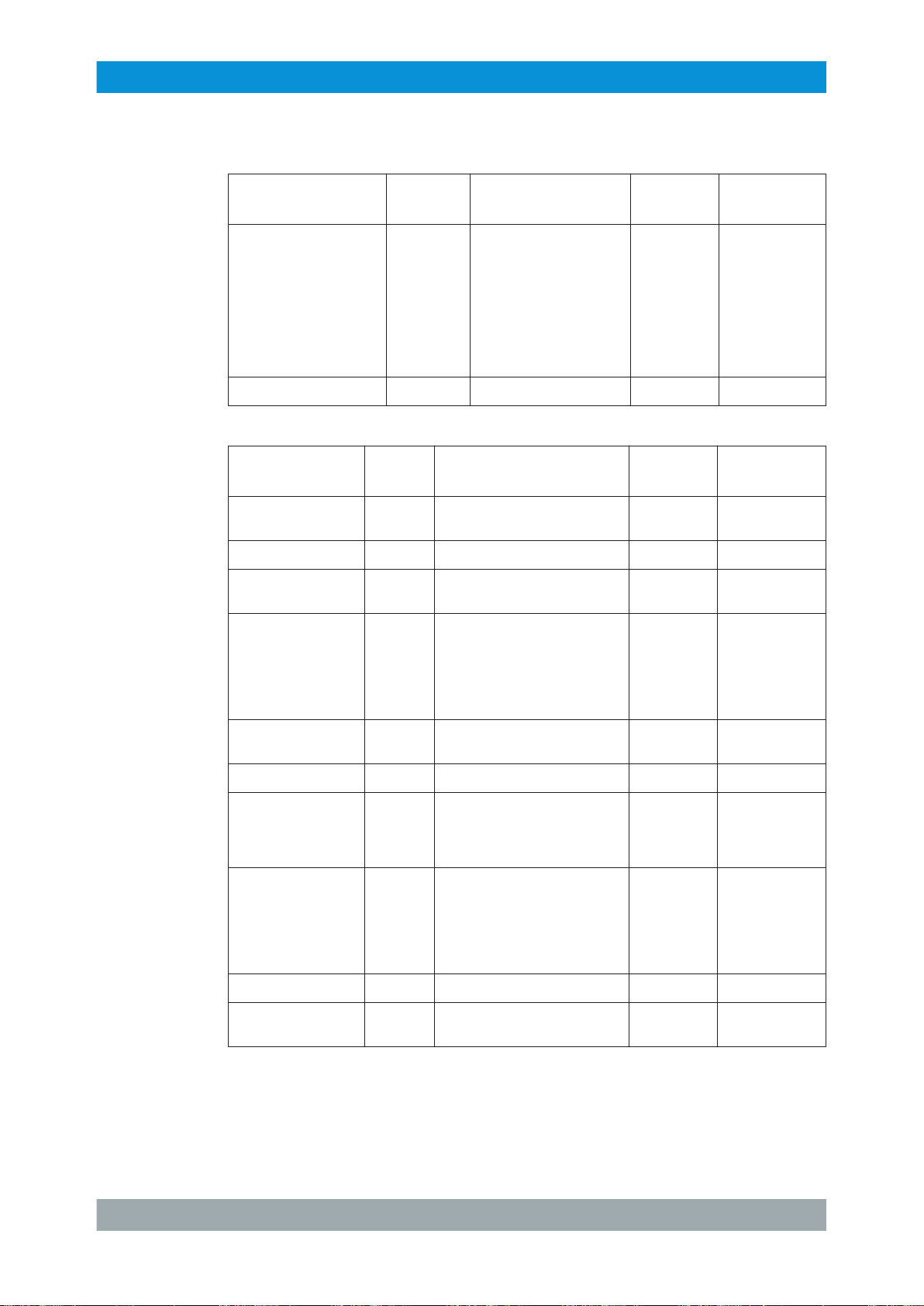
R&S®TLx9
R&S TLx9 Interface Description
Option Board Interfaces
Table A-47: X60D - RF IN/OUT: SMA socket 50
Signal
Name/Description
X60D Bidirectional P
GND Bidirectional
Table A-48: X86 - Control: 9-pin Sub-D socket
Signal
Name/Description
+12V_RFSW Input 12 V ± 0.5 V,
LOOP+ Output LVDS X86.2
GND Bidirec-
Direction Value range Connection
Direction Value range Connection
0 V X86.3 GND
tional
Ω
point
< 20 W
AVG, max.
174 MHz to 790 MHz
at 50 Ω load, s < 1.4
≤ 0.2 A X86.1 +12 V DC for
X60D.1 This port can be
X60D.2 GND / shield
point
Remarks
used as output to
a dummy load in
a TX 1+1 system
or as an input
from Antenna_B
in a single or
antenna 1+1 system.
Remarks
message relay
ControlPos1 Input LV-CMOS (2.5 V) X86.4 Commands the
RF relays to position 1 when connected to GND
(default: high
resistance)
0V_RFSW Bidirec-
tional
LOOP- Input LVDS X86.6
STATUS_POS1/2_SW Output LV-CMOS (2.5 V) X86.7 Position info of
ControlPos2 Input LV-CMOS (2.5 V) X86.8 Commands the
+12VIN Input 12 V ± 0.5 V, ≤ 2 A X86.9 +12 V DC backup
GND Bidirec-
tional
0 V X86.5 GND for mes-
sage relay
the RF relays
(from message
relay)
RF relays to position 2 when connected to GND
(default: high
resistance)
0 V X86.10.11 Shielding (GND)
83System Manual 2506.5060.02 ─ 03
Page 90

R&S®TLx9
R&S TLx9 Interface Description
Option Board Interfaces
84System Manual 2506.5060.02 ─ 03
 Loading...