

Signal Generation 212
Contents Overview R&S Addresses
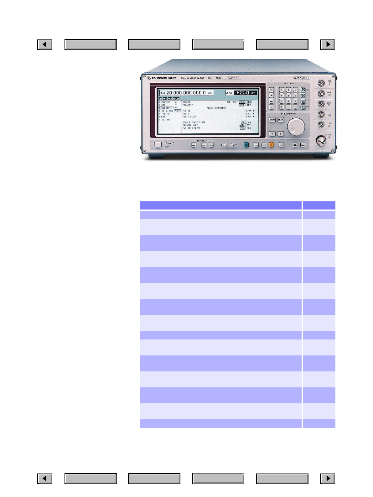
Microwave Signal Generator SMP
SMP02, 22: 0.01/2 to 20 GHz
SMP03: 0.01/2 to 27 GHz
SMP04: 0.01/2 to 40 GHz
Excellent signal characteristics
and high output power up to
40 GHz
Brief description
SMP is a reliable, high-precision signal source featuring high output
power, high spectral purity and excellent pulse modulation. It is able to supply signals for any measurements on
radar and communications receivers.
A wide range of extensions ensures
universal use in R&D, production,
EMC and environmental measurements as well as in material testing.
Main features
• High spectral purity
• Stable output frequency
• High output level:
SMP02 SMP22 SMP03 SMP04
>11.5 >20 >13 >10 dBm
at 20 20 27 40 GHz
• Fast settling after a frequency
change
• AM, FM, ϕM, pulse modulation
•Scan modulation
• RF, AF and level sweep
• Large choice of options for userspecific configuration
• Great ease of operation through
modern menu concept
Chapter Overview
Photo 41154
Type Index
Overview of options
Designation, functions Option
Reference Oscillator OCXO: aging <1 x10⁻⁹/day SM-B1
LF Generator: supplies sinewave, noise 0.1 Hz to 500 kHz,
triangular, squarewave 0.1 Hz to 50 kHz signals
FM/ϕM Modulator: FM DC to 1 MHz, ϕM DC to 100 kHz,
precision FM DC
Frequency Extension 0.01 to 2 GHz1): extends the lower
frequency limit to 10 MHz
Pulse Modulator 2 to 20 GHz1): on/off ratio >80 dB,
rise/fall time <10 ns; for SMP02 and SMP22 only
Pulse Modulator 2 to 27 GHz1): on/off ratio >80 dB,
rise/fall time <10 ns; for SMP03 only
Pulse Modulator 2 to 40 GHz1): on/off ratio >80 dB,
rise/fall time <10 ns; for SMP04 only
Pulse Modulator 0.01 to 2 GHz1): on/off ratio >80 dB,
rise/fall time <10 ns
Pulse Generator: provides single, delayed and double pulses SMP-B14
RF Attenuator 27 GHz1): allows level setting down to −130 dBm;
for SMP02, SMP22 and SMP03 only
RF Attenuator 40 GHz1): allows level setting down to −130 dBm;
for SMP04 only
Auxiliary Interface: V/GHz output, Z output for scalar network
analyzers
Rear Connectors for RF and AF1): to replace front-panel connectors; for
SMP02, SMP22 and SMP03 only
Rear Connectors for RF and AF1): to replace front-panel connectors; for
SMP04 only
1)
Factory-fitted option.
SM-B2
SM-B5
SMP-B11
SMP-B12,
model 02
SMP-B12,
model 03
SMP-B12,
model 04
SMP-B13
SMP-B15
SMP-B17
SMP-B18
SMP-B19
SMP-B20
Contents Overview R&S Addresses
Chapter Overview
Type Index

Signal Generation 213
12
Contents Overview R&S Addresses
Chapter Overview
Specifications in brief
Frequency
Range standard with option SMP-B11
SMP02, SMP22 2 to 20 GHz 10 MHz to 20 GHz
SMP03 2 to 27 GHz 10 MHz to 27 GHz
SMP04 2 to 40 GHz 10 MHz to 40 GHz
Resolution 0.1 Hz
Setting time (to within <1 x 10
after IEC/IEEE-bus delimiter <(11 ms + 5 ms/GHz)
Reference frequency standard option SM-B 1
Aging (after 30 days of operation) 1 x 10
Temperature effect (0 to 55°C) 2 x 10
Spectral purity
Spurious signals SMP02 SMP22 SMP03 SMP04
Harmonics:
f <1.8 GHz <−30 dBc <−25 dBc <−30 dBc <−30 dBc
f ≥1.8 GHz <−40 dBc <−25 dBc <−40 dBc <−40 dBc
Harmonics with options SMP-B12, -B13 (pulse modulation on):
f <1.8 GHz <−25 dBc <−25 dBc <−25 dBc <−25 dBc
f ≥1.8 GHz <−25 dBc <−25 dBc <−25 dBc <−25 dBc
Subharmonics:
f ≤20 GHz none none none none
f >20 GHz −−<−40 dBc <−30 dBc
Nonharmonics at >10 kHz from carrier:
f <2 GHz typ. typ. typ. typ.
2 to 20 GHz <−60 dBc <−60 dBc <−60 dBc <−60 dBc
f >20 GHz −−<−54 dBc <−54 dBc
SSB phase noise, 1 Hz bandwidth, FM off:
Frequency range 100 Hz 1 kHz 10 kHz 100 kHz
10 MHz to <2 GHz <−64 dBc <−92 dBc <−98 dBc <−101 dBc
2 to 10 GHz <−64 dBc <−92 dBc <−98 dBc <−101 dBc
>10 to 20 GHz <−58 dBc <−86 dBc <−92 dBc <−95 dBc
>20 to 27/40 GHz <−54 dBc <−80 dBc <−86 dBc <−92 dBc
Level
Maximum level SMP02, SMP22:
Frequency range SMP02, option SMP-B15 SMP22, option SMP-B15
10 MHz to <2 GHz >+17 dBm >+17 dBm >+17 dBm >+17 dBm
2 to 20 GHz >+11.5 dBm>+10 dBm >+20 dBm >+18.5 dBm
Maximum level SMP03, SMP04:
Frequency range SMP03, option SMP-B15 SMP04, option SMP-B17
10 MHz to <2 GHz >+12 dBm >+12 dBm >+12 dBm >+12 dBm
2 to <18 GHz >+10 dBm >+8.5 dBm >+10 dBm >+8.5 dBm
18 to 20 GHz >+6 dBm >+4.5 dBm >+6 dBm >+4.5 dBm
>20 to 27/33 GHz >+13 dBm >+11 dBm >+12 dBm >+10 dBm
>33 to 40 GHz – – >+10 dBm >+8 dBm
Modulation any combination of AM scan,
Amplitude modulation internal, external AC/DC
Modulation depth/resolution 0 to 90%/0.1%
AM distortion at AF=1 kHz
(m=60%), f >50 MHz <1%, typ. <0.5%
Modulation frequency range DC to 100 kHz
Frequency modulation int., ext. AC/DC, locked/unlocked,
Standard frequency modulation without option SM-B5
Maximum deviation f ≤20 GHz: 10 MHz
FM distortion at AF=50 kHz
and 500 kHz deviation <0.5%, typ. 0.05%
Modulation frequency range
Locked mode 10 kHz to 5 MHz
Unlocked mode DC to 5 MHz
FM with option SM-B5 standard FM available
Maximum deviation/resolution
f ≤20 GHz 1 MHz/<1%, min. 10 Hz
-6
)
−6
/year <1 x 10⁻⁹/day
−6
(<+8 dBm) (<+8 dBm) (<+3 dBm) (<±0 dBm)
(<+10 dBm) (<+15 dBm) (<+3 dBm) (<±0 dBm)
(<+8 dBm) (<+8 dBm) (<+3 dBm) (<±0 dBm)
(<+11 dBm) (<+11 dBm) (<+3 dBm) (<±0 dBm)
<−60 dBc <−60 dBc <−60 dBc <−60 dBc
offset from carrier
w/o with w/o with
w/o with w/o with
FM (ϕM) and pulse modulation
two-tone with two separate channels
FM1 and FM2
f >20 GHz: 20 MHz
<5 x 10
−8
Type Index
f >20 GHz 2 MHz/<1%, min. 20 Hz
FM distortion at AF=1 kHz
and 500 kHz deviation <0.5%, typ. 0.05%
Modulation frequency range DC to 1 MHz
Phase modulation with option SM-B5; int., ext. AC/DC,
Maximum deviation/resolution
f ≤20 GHz 10 rad/<1%, min. 0.001 rad
f >20 GHz 20 rad/<1%, min. 0.002 rad
ϕM distortion at AF= 1 kHz
and 5 rad deviation <1%
Modulation frequency range DC to 100 kHz
ASK modulation external
Max. modulation depth/resolution 90%/0.1%
Data rate 0 to 200 kHz
FSK modulation external
Maximum shift standard FM with option SM-B5 Resolution
f ≤20 GHz 10 MHz 1 MHz <1%, min. 10 Hz
f >20 GHz 20 MHz 2 MHz <1%, min. 20 Hz
Data rate (standard FM)
Locked mode 20 kHz to 2 MHz
Unlocked mode 0 to 2 MHz
Data rate with option SM-B5 0 to 2 MHz
Pulse modulation ext., int. with option SMP-B14
Frequency range ≥2 GHz -B13:10 MHz to 2 GHz
On/off ratio >50 dB (level >0 dBm) >80 dB
Rise/fall time
(10/90%) <500 ns <10 ns
Minimum pulse width 1 µs20 ns
Pulse repetition
frequency 0 to 500 kHz 0 to 10 MHz
Pulse delay typ. 100 ns typ. 50 ns
Video feedthrough <15 mV (peak value) <15 mV (peak value)
Further data
Internal modulation generator see SMT, page 198
LF generator (option SM-B2) see SMT, page198
Pulse generator (option SMP-B14) see SMT (option SM-B4), page 198
2nd RF output 2 to 20 GHz, 0 dBm
Sweep see SMT, page 198
Auxiliary interface with option SMP-B18
V/GHz output output voltage proportional to fre-
Remote control IEC 625 (IEEE 488); SCPI 1993.0
Power supply 90 to 132/180 to 265 V,
Dimensions (WxHxD) 435 mmx192 mmx570 mm
Weight 27 kg for fully equipped unit
w/o option with option
SMP--B12, -B13 SMP--B12, -B13
two-tone with two separate channels
ϕM1 and ϕM2
-B12: ≥2 GHz
quency, 0.5 or 1 V/GHz selectable
47 to 440 Hz, max. 400 VA
Ordering information
Signal Generator SMP02 1035.5005.02
Options
Frequency Extension 0.01 to 2 GHz
Pulse Modulator
2 to 20 GHz (SMP02, SMP22) SMP-B12 1036.5750.02
2 to 27 GHz (SMP03) SMP-B12 1036.5750.03
2 to 40 GHz (SMP04) SMP-B12 1036.5750.04
Pulse Modulator 0.01 to 2 GHz
Pulse Generator SMP-B14 1036.7347.02
RF Attenuator 27 GHz
RF Attenuator 40 GHz
Auxiliary Interface SMP-B18 1036.8920.02
Rear Connectors for AF, RF
up to 27 GHz SMP-B19 1039.4303.02
up to 40 GHz SMP-B20 1039.4503.02
Reference Oscillator OCXO SM-B1 1036.7599.02
LF Generator SM-B2 1036.7947.02
FM/ϕM Modulator SM-B5 1036.8489.02
1)
Factory-fitted option.
1
)
1
) SMP-B15 1036.5250.02
1
) SMP-B17 1036.5550.02
1
)
SMP22 1035.5005.22
SMP03 1035.5005.03
SMP04 1035.5005.04
1
) SMP-B11 1036.6240.02
1
) SMP-B13 1036.7147.02
Contents Overview R&S Addresses
Chapter Overview
Type Index
 Loading...