


¸SMJ100A Vector Signal Generator
Versatility in signal generation
Version
Version
01.01
01.00
May
November
2007
2004

2 ¸SMJ100A Vector Signal Generator
The multipurpose signal generator
The ¸SMJ100A meets all challenges
that diverse applications place on modern
vector signal generators. For example, it
offers the signal quality and flexibility required in research and development – not
to mention a convenient graphical user
interface (GUI). And this is by no means
all the ¸SMJ100A has to offer – a
fact that becomes evident in production,
where it excels with its flexible baseband
and low setting times. The baseband
meets all requirements, from providing
1)
CDMA 2000 is a r egistere d trademark of the Telecommunications Indus try Ass ociation ( TIA - USA ).
realtime signals to replaying precalculated waveforms.
Equipped with a 3 GHz or 6 GHz
frequency option, the ¸SMJ100A
covers all important frequency bands
essential in digital RF transmission.
The internal baseband generator option handles a multitude of digital
standards, e.g. GSM/EDGE, 3GPP FDD
and CDMA2000® 1). Its characteristics
make the ¸SMJ100A the ideal
multipurpose vector signal generator,
supporting a wide variety of applications.
To handle future standards, the
¸SMJ100A features a large bandwidth; thus, new standards such as
WiMAX pose no problem. The internal
arbitrary waveform generator is proof
of its versatility. It offers sequences
up to 64 Msamples in length and can
be used with diverse signals from
¸WinIQSIM™ or Matlab.
High signal quality
I/Q modulator with 200 MHz RF band-
width
Low SSB phase noise of typ. –133 dBc
(20 kHz carrier offset, f = 1 GHz, 1 Hz
measurement bandwidth)
Wideband noise of typ. –153 dBc
(>5 MHz carrier offset, f = 1 GHz,
1 Hz measurement bandwidth)
Excellent ACLR performance of typ.
+69 dB for 3GPP FDD (test model 1,
64 DPCHs)
High-stability reference oscillator as
standard
High level repeatability
Ideal for production
Very short frequency and level set-
ting times (<5 ms); only 450 µs in List
mode for frequency changes
Electronic attenuator up to 6 GHz over
the entire level range from –145 dBm
to +13 dBm
Internal baseband versatility
Four code channels in realtime for
3GPP FDD
Different modulation in each slot for
GSM/EDGE
Baseband generator with realtime
signal generation
Arbitrary waveform generator with up
to 64 Msamples
Signals up to 80 MHz bandwidth if
the internal baseband generator is
used
Arbitrary waveform generator sup-
ported by Simulation Software
¸WinIQSIM™
Internal 30 Gbyte hard disk provided
as standard for storing waveforms
and modulation data
Ease of use
Color display with 800 × 600 pixels
(SVGA format)
Intuitive user interface with graphical
display of signal flow (block diagram)
Graphical display of baseband signal
through built-in transients recorder
Context-sensitive Help system
Tooltips for all edit fields
Connectivity
Remote control via GPIB and LAN
USB connectors for keyboard, mouse
and memory stick
User-selectable trigger and marker
signals
¸SMJ100A Vector Signal Generator 3

4 ¸SMJ100A Vector Signal Generator
Easy operation ...
Turn
Click
To permit intuitive operation, the
¸SMJ100A is equipped with a large
color display that provides an innovative GUI. The signal flow within the
instrument is displayed in a block diagram, with each block representing a
functional unit such as RF or baseband.
The individual functions and settings are
thus clearly assigned. All active components are highlighted in color, providing
a quick and effective overview.
The rotary knob plays a key role in
¸SMJ100A operation. It provides
a quick means of navigating in the
block diagram or in various menus and
selecting parameters by using just one
hand. Of course, hardkeys that speed up
operation are available for basic functions such as setting frequency and level.
Block diagram of the ¸SMJ100A
A window structure – like offered by
today’s computer operating systems
– is the natural evolution of the GUI.
This structure allows several different
menus to be open at the same time, so
that switching between them is possible
by using the Winbar. This structure is
yet another element that contributes to
swift and easy ¸SMJ100A operation.
Rotary knob for menu navigation
¸SMJ100A softkeys and hardkeys for windows management

A context-sensitive Help function supports intuitive menus. The
¸SMJ100A Help function is particularly useful if you need information
about the parameters available within
the different standards.
Each edit window offers a tooltip function that specifies the setting range of
the selected parameter. If more detailed
information is required, the Help function comes in handy. It not only provides
background information about various
parameters, but also supports the programming of an automatic test setup
with remote-control commands. The
Help function also provides links to related topics.
Last but not least, the Help function
includes the entire operating manual.
When software updates are installed,
the documentation will automatically be
updated as well.
Tooltip indicating the permissible frequency setting range
Context-sensitive Help system
The ¸SMJ100A comes equipped
with an internal graphics block, which is
based on an internal transients recorder
that analyzes the signals in the baseband chain. The graphics block provides
various displays such as spectrum,
I/Q and CCDF. This allows the signal to
be quickly and easily checked without
switching the signal generator directly to
the analyzer.
Graphics block with constellation, CCDF and I/Q diagrams
¸SMJ100A Vector Signal Generator 5

6 ¸SMJ100A Vector Signal Generator
Signal quality
–40
–50
–60
–70
–80
–90
–100
–110
–120
–130
–140
–150
–160
SSB phase noise / dBc(1 Hz)
1 10 10
2
10
3
10
4
10
5
10
6
10
7
2,1 GHz
Frequency offset / Hz
100 MHz
850 MHz
5,7 GHz
A
Ref
-18.4 dBm
Att 5 dB*
*
*
*1 RM
CLRWR
RBW 30 kHz
VBW 300 kHz
SWT 2 s
NOR
SGL
EXT
*
Center 2 GHz Span 25.5 MHz2.55 MHz/
-9
0
-80
-7
0
-60
-50
-40
-3
0
Tx Channel W-CDMA 3GPP FWD
Ba
ndwidth
3.84 MHz
Po we r - 14. 61 dB m
Adjacent Channel
Band
wid
th 3.84 MHz
Lo we r - 69. 02 dB
Spac
ing
5 MHz
Up pe r - 68. 72 dB
Alternate Channel
Band
wid
th 3.84 MHz
Lo we r - 71. 20 dB
Spacing 10 MHz
Up pe r - 70. 84 dB
-110
-100
POS -18,442 dBm
A
Ref
1.30
dBm
Ref
1.30
dBm
Ref
1.30
dBm
Result Summary
CF 2.15 GHz CPICH Slot 0
Chan Code 2
B
Att*
0 dB
Att*
0 dB
Ref
1.30
dBm
Ref
1.30
dBm
Ref
1.30
dBm
Att*
0 dB
Att*
0 dB
1
CLRWR
Code Power Relative
CF 2.15 GHz CPICH Slot 0
Chan Code 2
64 Ch/
1
CLRWR
Chan Slot 7
Chan Slot 7
Start Ch 0 Stop Ch 511
SR 30 ksps
SR 30 ksps
-63
-56
-49
-42
-35
-28
-21
-14
-7
GLOBAL RES ULTS FOR FR AME 0:
Total Powe r
Chip Rate Error
IQ Offset
Composite EVM
CPICH Slot No
-10.94
-0.25
0.13
0.39
0
dBm
ppm
%
%
Carrier Fr eq Error
Trigger to Frame
IQ Imbalan ce
Pk CDE (15 ksps)
No of Acti ve Chan
131.61
1.715710
0.02
-67.64
68
Hz
ms
%
dB
CHANNEL RE SULTS
Symbol Rat e
Channel Co de
No of Pilo t Bits
Channel Po wer Rel
Symbol EVM
30.00
2
8
-6.00
0.28
ksps
dB
% rms
Timing Off set
Channel Sl ot No
Modulation Type
Channel Po wer Abs
Symbol EVM
22016
7
QPSK
-26.95
0.45
Chips
dBm
% Pk
To meet the demands of an all-purpose
instrument, the basic RF parameters
must be correct. SSB phase noise is one
of the key figures. The ¸SMJ100A’s
good performance with regard to SSB
phase noise is due to its internal architecture, featuring a modern multiloop
concept as well as a high-stability reference oscillator as standard.
Typical SSB phase noise in the relevant frequency bands
In addition to its basic RF characteristics,
the instrument also offers high application-related performance. The adjacentchannel leakage ratio (ACLR) is an important key figure in 3GPP and especially
relevant for testing amplifiers.
Typical ACLR performance for 3GPP FDD (test model 1, 64 DPCHs)
Demodulation of a 3GPP FDD signal
Another significant parameter is the error vector magnitude (EVM), which is
essential in module and receiver tests,
where bit errors are measured on the
DUT. The better the signal quality of the
generator, the sharper the test criterion
– a characteristic that pays off especially in production. What makes the
¸SMJ100A distinctive is that both
excellent ACLR and outstanding EVM are
provided without requiring any changes
in the settings.

In addition to the main mobile radio
IEEE 802.11a
Frequency: 5.7 GHz Signal Level: -11.2 dBm External Att: 0 dB
Sweep Mode: Single
Trigger Mode: Free Run
Trigger Offset: -10 µs
Burst Type: Direct Link Burst Modulation:
54 Mbps 64 QAM No Of Data Symbols: 1/1366
Capture Memory No of Samples 10000
Marker 1
Capture Time 500 µs
Gate Off
- 7.37
Ref-1.2 dBm Att/El 0.00 / 10.00 dB Burst 3 (3) 0 s
0.0000 ms
0.5000 ms0.0500 ms/div
-69
-61
-53
-45
-37
-29
-21
-13
-5
1
A
SGL
EVM vs Carrier Marker 1 -51.96 dB
Carrier
1
-26 Carrier 26 Carrier4 Carrier/div
-90
-80
-70
-60
-50
-40
-30
-20
-10
1
1 EVM
AVG
2 EVM
CLRWR
B
IEEE 802.11a
Frequency:
5.7 GHz
Signal Level:
-11.2 dBm External Att:
0 dB
Sweep Mode: Single
Trigger Mode: Free Run
Trigger Offset: -10 µs
Burst Type:
Direct Link Burst Modulation:
54 Mbps 64 QAM No Of Data Symbols: 1/1366
Result Summary
No. of Bursts
7
Min
Mean
Limit
Max
Limit Unit
EVM All Carriers
0.36
0.39
5.62
0.42 5.62 %
- 48.82
- 48.29 - 25.00
- 47.63 - 25.00 dB
EVM Data Carriers
0.37
0.39
5.62
0.42 5.62 %
- 48.72
- 48.20 - 25.00
- 47.53 - 25.00 dB
EVM Pilot Carriers
0.29
0.33 39.81
0.38 39.81 %
- 50.81
- 49.55 - 8.00
- 48.42 - 8.00 dB
IQ Offset
- 67.16
- 64.72 - 15.00
- 62.35 - 15.00 dB
Gain Imbalance
- 0.09
- 0.02
0.02
%
- 0.01
- 0.00
0.00
dB
Quadrature Error
0.01
0.04
0.08
°
Center Frequency Error
317.17
353.68 ± 105200
394.17 ± 105200 Hz
Symbol Clock Error
1.12
6.27
± 20
11.40 ± 20 ppm
Burst Power
- 11.54
- 11.54
- 11.53
dBm
Crest Factor
7.73
7.73
7.74
dB
standards, the ¸SMJ100A – because of its large bandwidth and ample
frequency coverage – is ideal for important wireless network standards such
as WLAN IEEE 802.11 and WiMAX IEEE
802.16. Here, too, the ¸SMJ100A’s
EVM capabilities underscore its standing
as an all-purpose instrument. In addition, the ¸SMJ100A offers excellent
performance with broadband signals,
which is due to the high linearity of the
baseband and the I/Q modulator.
EVM versus the individual subcarriers with a 54 Mbit/s WLAN signal in accordance with IEEE 802.11a
¸SMJ100A Vector Signal Generator 7
¸SMJ100A with PC and WLAN
Result table for a WLAN IEEE 802.11 signal

8 ¸SMJ100A Vector Signal Generator
Full power in the baseband
The flexible baseband generator in the
¸SMJ100A is the heart of the instrument. It includes a universal coder
(for calculating signals in realtime) as
well as an integrated arbitrary waveform
generator with a memory depth of up to
64 Msamples, sufficient even for long
complex test signals. Enhanced with a
high system bandwidth of up to 80 MHz,
the ¸SMJ100A can handle various
current and future wireless applications.
A special feature of the ¸SMJ100A
is its realtime capability. For 3GPP FDD,
it provides up to four code channels in
realtime. However, to generate a scenario with additional channels, further code
channels can be added to the signal. In
the uplink, the ¸SMJ100A supplies
signals with different radio measurement channels (RMC). Moreover, the
¸SMJ100A provides a maximum of
64 additional mobile phones for simulating the actual network load for receiver
tests on the base station.
Its architecture enables the
¸SMJ100A to support important
standards. For example, mobile radio standards such as GSM/EDGE,
WCDMA 3GPP or CDMA2000® are already integrated. And other systems
such as WLAN IEEE 802.11, WiMAX and
GPS are also covered.
Four code channels in realtime with additional background channels
The ¸SMJ100A thus generates
the reference measurement channels
in accordance with the specifications
laid down in the 3GPP TS 25.141 and
TS 25.101 standards. Complete channel
coding in line with the standard is included and can be changed for test purposes.
To stress the DUT during receiver testing, signals with varying code channel
levels are used. Such a scenario may result when a mobile phone is in motion,
for example. According to the 3GPP standard, each slot contains a field for controlling the DUT output level. In addition
to testing the actual transmit power control (TPC), the level of the relevant code
channel can be varied.
Channel coding selection
Receiver tests: The ¸SMJ100A changes the output power of the code channel
The ¸SMJ100A can selectively gen-
P
CPICH
PSCH
SSCH
PCCPCH
SCC CH
PICH
SPDSH CH-16QAM
HSPDSCH-16Q AM
HSPDSCH-16Q AM
HSSCCH
15.0
-.-
-.-
15.0
0
---
--1
active
active
active
active
15.0
15.0
240.0
3
16
4
active
active
active
240.0
240.0
30.0
6
12
9
active
active
active
---
---
---
--OFF
---
---
---
---
--0
---
-22.40
-25.93
-25.54
-22.40
-30.40
-30.39
--- --- -16.44
---
---
---
---
-21.27
-16.51
--- --- -26.40
-19.38
-10.26
-5.50
-15.39
30720
0
0
0
-5.43 0
Pwr Rel
[dB]
T Offs
[Chips]
-11.39
-14.92
-14.53
-11.39
-19.39
---
---
---
--0
Status TFCI PilotL
[Bits]
Pwr Abs
[dBm]
Chan Type Symb Rate
[ksps]
Chan#
Channel Table
CF 2.1 GHz CPICH Slot 4
Chan Code 4
Chan Slot 4
SR 240 ksps
Ref
0.60
dBm
Att
0 dB
A
R e f
0 . 6 0
d B m
R e f
0 . 6 0
d B m
R e f
0 . 6 0
d B m
1
C L R W R
C o d e
P o w e r
R e l a t i v e
C F
2 . 1
G H z C P I C H
S l o t
4
C h a n
C o d e
4
6 4
C h /
A
R e f
0 . 6 0
d B m
R e f
0 . 6 0
d B m
R e f
0 . 6 0
d B m
S y m b o l
C o n s t e l l a t i o n
C F
2 . 1
G H z C P I C H
S l o t
4
C h a n
C o d e
4
B
A t t *
0
d B
A t t *
0
d B
A t t *
0
d B
A t t *
0
d B
C h a n
S l o t
4
C h a n
S l o t
4
S t a r t
C h
0
S t o p
C h
5 1 1
- 4 . 4 0 4
4 . 4 0 4
S R 2 4 0
k s p s
S R 2 4 0
k s p s
- 6 3
- 5 6
- 4 9
- 4 2
- 3 5
- 2 8
- 2 1
- 1 4
- 7
0 1 1 0 1 0 1 0 1…
Bit error
1 0 1 1…
Block error
0
Information data
CRC attachment
Tail bit attachment
Conv. coding R=1/3
Rate matching
1st interleaving
804
686
686
244 16 8
DATA CRC
244
DTCH
CRC16
360
308
308
100 12 8
100 12
100
DCCH
CRC12
Tail8Tail8
Transmission
1
erate bit errors and block errors in the
coded signal. This allows the internal
bit error ratio (BER) and block error ratio
(BLER) calculations of a base station to
be checked in line with TS 25.141.
In addition to conventional 3GPP signals, the flexible baseband also allows
high speed downlink packet data access
(HSDPA). Thus, the ¸SMJ100A already includes test model 5 as defined
in TS 25.141 of the 3GPP specification.
In addition to the Continuous mode, the
¸SMJ100A also permits the Packet
mode for HSDPA channels in the downlink in line with TS 25.211. The uplink
provides the required control channels.
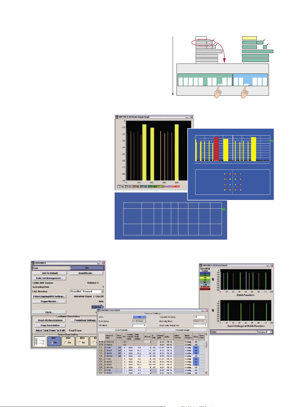
In addition to 3GPP FDD, the
¸SMJ100A supports CDMA2000®
in its 1X mode with full channel coding. It also covers cdmaOne as a subset. Similar to 3GPP FDD, where HSDPA
is a special mode for high data rates,
CDMA2000® includes 1xEV-DV, also
known as radio configuration 10 (RC 10),
which the ¸SMJ100A supports.
Insertion of bit errors and block errors into the output signal
Code domain display in the ¸SMJ100A with three HSDPA data channels and corresponding
results from the signal analyzer (code domain, channel list and constellation diagram of an HSDPA
data channel)
CDMA2000® in the ¸SMJ100A
¸SMJ100A Vector Signal Generator 9
10 ¸SMJ100A Vector Signal Generator
Slot 0 1 2 3 4 5 6 7 0 1
Frame
P1
P2
P3
P4
P5
P6
P7
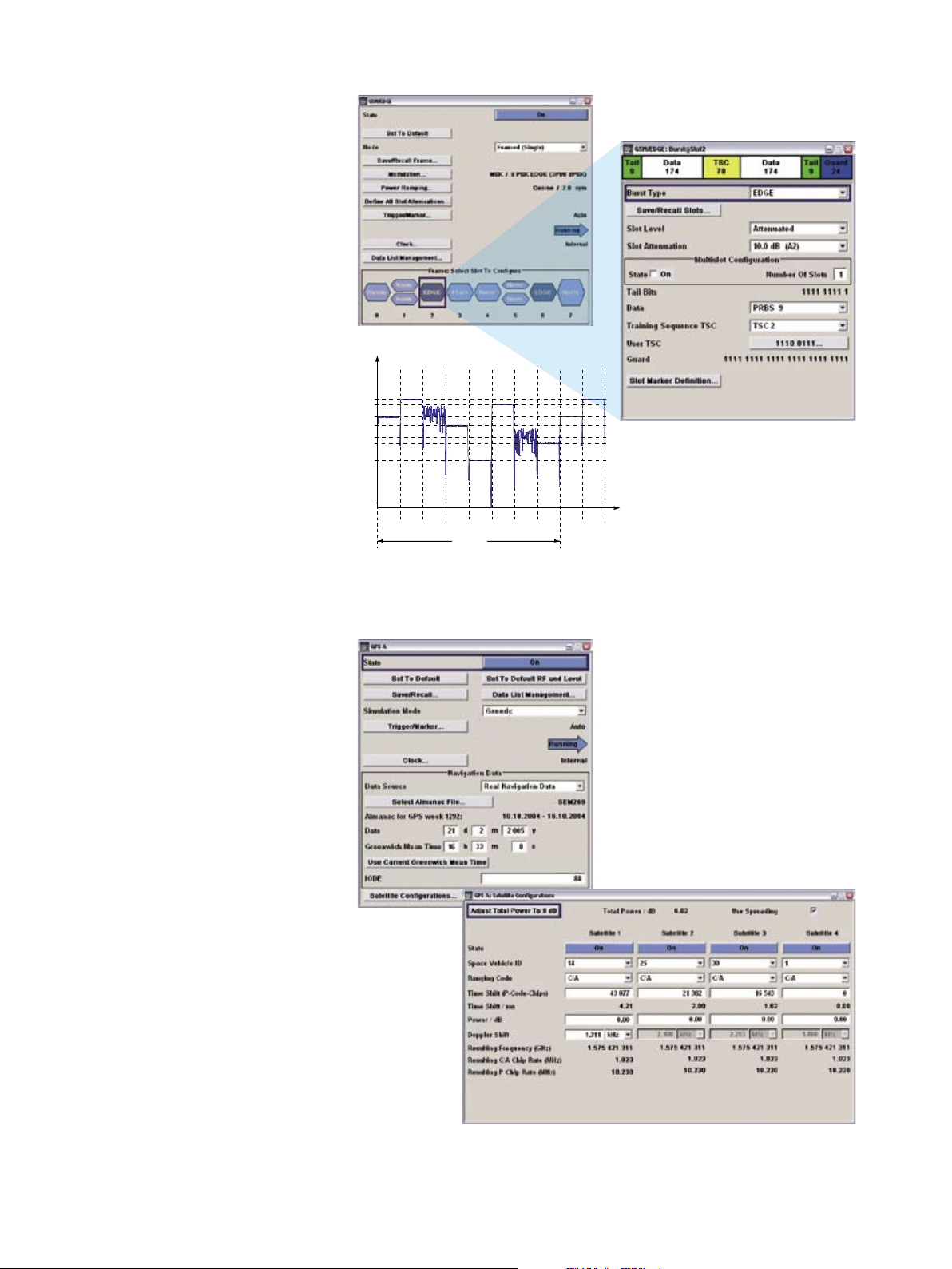
Although third-generation mobile radio
technology is already being implemented, the second generation with GSM/
EDGE is still highly important for many
users. The internal GSM/EDGE option
offers all burst types of the standard, including half-rate slots where both users
are set individually. Moreover, multislot
configurations are supported so that
multiple slots can be assigned to one
user with one common data source.
The ¸SMJ100A supports a maximum
of eight different slot levels, allowing a
specific level to be assigned to each slot
in a frame. Another important feature is
the capability to change between GMSK
and 8PSK EDGE modulation from one
slot to the next, such as when a change
from normal burst to EDGE burst occurs
in a base station. To permit maximum
flexibility, the ¸SMJ100A allows
two different frames to be defined; the
repetition rate is user-definable for each
frame. This makes it possible, for example, to simulate a change from GMSK to
8PSK EDGE modulation in one timeslot
from one frame to the next.
Change between GSM and EDGE modulation from one slot to the next in the ¸SMJ100A
The internal digital GPS standard generates static signals for the Global Positioning System with up to four satellites. As a result, the ¸SMJ100A can
perform not only basic RF tests but also
a function test of a GPS receiver. Since
actual Almanach data can be used, signals are realistic. The GPS time can also
be set.
GPS with up to four satellites

In addition to the extensive functions
in the mobile radio standards, the
¸SMJ100A also covers the wireless
LAN standards IEEE 802.11a, IEEE 802.11b
and IEEE 802.11g with complete channel
coding. In the OFDM modes, all data rates
of the IEEE 802.11a and IEEE 802.11g
standards from 6 Mbps to 54 Mbps are
supported. The same is true for the CCK
mode with data rates from 1 Mbps to
11 Mbps, as well as for the PBCC mode
where an optional expansion with data
rates up to 22 Mbps has been added to
the IEEE 802.11 g standard.
The address of the specified receiver can
be defined in the MAC header. Since
data is transmitted in packets of different
lengths and without a defined time grid,
both idle time and packet interval can be
set. To perform initial receiver tests, the
signal can also be provided as a continuous data stream without packet structure.
Operating menu for wireless LAN standard IEEE 802.11 (a, b, g)
The IEEE 802.16 standard – also referred
to as WiMAX – is of broad interest as
a wireless connection for the last mile.
The ¸SMJ100A supports release
2004, revision d, of this system, including channel coding. Both versions,
OFDM and OFDMA, are included. The
¸SMJ100A offers various uplink and
downlink duplex capabilities, including
both FDD and TDD.
The user interface provides separate operating menus for the OFDM and OFDMA
modes. OFDM on the one hand has a defined FFT length of 256, and only one set
of subchannels is used simultaneously;
what’s of interest here are the different
data bursts with the individual subcarrier modulations. On the other hand,
OFDMA has a considerably larger FFT
size of 2048, so that different subchannel
groups can be assigned to different users, which is reflected in the subchannel
map of the OFDMA configuration.
OFDM and OFDMA configuration in the WiMAX system
¸SMJ100A Vector Signal Generator 11
12 ¸SMJ100A Vector Signal Generator
Added value
Receiver tests require not only an ideal
signal, but often a realistic signal with
additive noise. To achieve this, the
¸SMJ100A allows additive white
Gaussian noise (AWGN) to be superimposed on the ideal signal. The signalto-noise ratio can be set within a wide
range.
The 3GPP standard, for example, stipulates tests with noisy signals. Exact level
control supports these sensitivity measurements since this is exactly where
high-precision level settings and level
changes are called for.
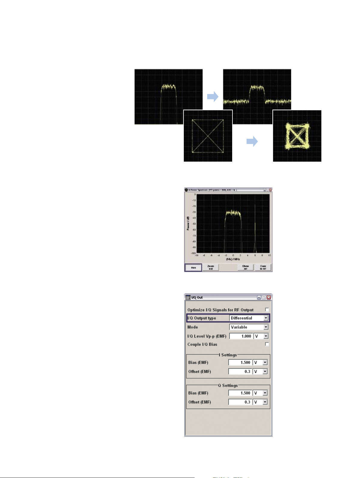
The Noise Only and CW Interferer modes
are attractive add-on functions. With
Noise Only, the ¸SMJ100A can act
as a defined noise source. The other
function allows a required CW interferer
to be internally added to the wanted signal – a feature that is especially useful
for receiver tests (blocking tests).
Influence of additive white noise on spectrum and vector diagram
As an all-purpose instrument, the
¸SMJ100A not only provides an RF
output but also I/Q outputs. These come
in useful if the receiver has to be tested
at an early stage in development without
an RF frontend being available, or if only
the baseband module performance is of
interest.
The instrument features more than just
single-ended outputs; it also provides
differential I/Q outputs with variable levels and offsets. Such versatility allows
the ¸SMJ100A to be adapted to the
DUT – without requiring an additional
matching circuit.
CW interferer added by using the AWGN option
User interface for I/Q outputs
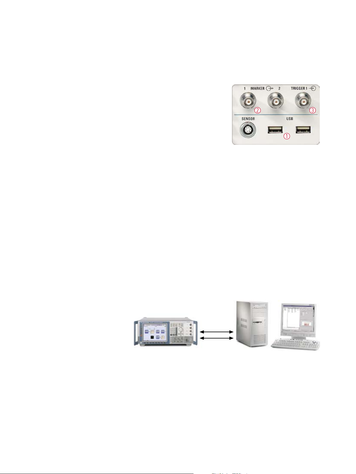
Connectivity
LAN
IEC/IEEE bus
Front panel
An external mouse and keyboard can
be plugged into the front panel via USB
connectors. Connecting memory sticks
comes in very handy. This allows waveforms for the internal arbitrary waveform
generator to be easily transmitted. Thus,
the ¸SMJ100A need not be connected via remote control to generate
¸WinIQSIM™ signals, for example.
This feature definitely simplifies routine
lab work.
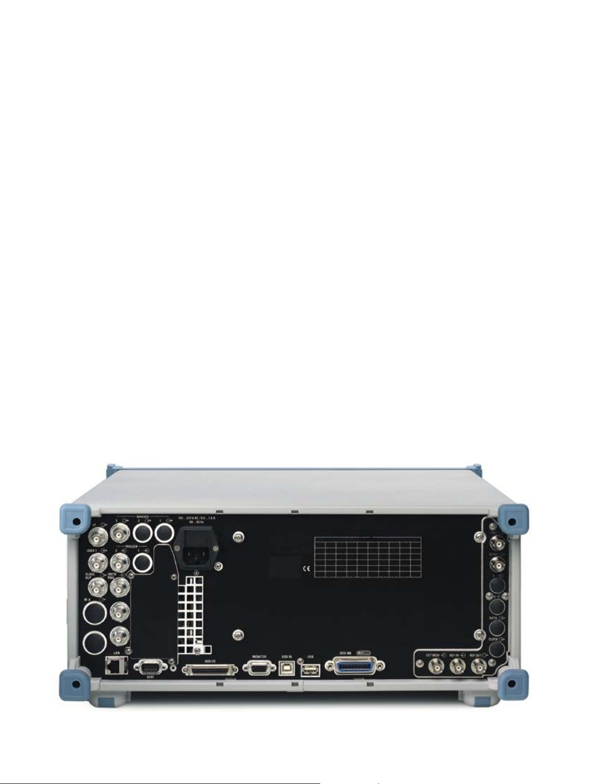
Rear panel
Besides remote-control interfaces, other
useful connectors are available at the
rear. Additional marker outputs plus another trigger input are provided.
An external monitor can be connected
via the VGA output.
In addition to a trigger input, there are
two marker outputs at the front panel,
making lab setup simple. The trigger
input allows the ¸SMJ100A to be
involved in DUT timing. The marker outputs offer different signals, depending
on the standard. In GSM/EDGE, for example, slot or frame markers are available, in 3GPP FDD a radio frame marker.
Flexible design
The option concept ensures that the
¸SMJ100A can be optimally configured to meet diverse applications. Future
expansions with additional options – as
required by new applications – pose no
problem.
An all-purpose instrument also needs to
offer low cost of ownership. This is why
the ¸SMJ100A comes with a threeyear calibration cycle, which increases
its availability and reduces calibration
costs.
Remote control
The ¸SMJ100A can be remote controlled both via the conventional
IEC/IEEE bus and via the LAN interface;
due to its higher transmission rate,
the LAN interface yields advantages in
speed. Moreover, the LAN allows remote
operation via Windows Remote Desktop.
¸SMJ100A Vector Signal Generator 13
¸SMJ100A remote control via IEC/IEEE bus or LAN

14 Vector Signal Gener ator ¸SMJ100A
Condensed data
Frequency
Frequency range 100 kHz to 3 GHz/6 GHz
Setting time <5 ms
Setting time in List mode <450 µs
Level
Range –144 dBm to +13 dBm (PEP)
[+16 dBm in overrange]
Setting time <5 ms
Spectral purity (at f = 1 GHz)
Nonharmonics
Carrier offset >10 kHz
Carrier offset >850 kHz
SSB phase noise
(20 kHz carrier offset, 1 Hz mea
surement bandwidth) typ. –133 dBc
Wideband noise
(carrier offset >5 MHz, 1 Hz measurement bandwidth)
ACLR performance
3GPP test model 1, 64 DPCHs
I/Q bandwidth (RF)
Internal 80 MHz
External 200 MHz
Supported modulation types
ASK
FSK
PSK
QAM
Supported standards and digital
systems
Interfaces
1)
The
Bluetooth®
such marks by R ohde & Schwarz is under licens e.
word mark and lo gos are owne d by the Blueto oth SIG, Inc . and any use of
<–80 dBc
<–86 dBc
-
typ. –153 dBc (CW)
typ. –146 dBc (I/Q modulation)
typ. 69 dB
0 % to 100 %
MSK, 2FSK, 4FSK
BPSK, QPSK, OQPSK,
π/2 DBPSK, π/4 DQPSK,
π/8 D8PSK, π/4 QPSK, 8PSK,
8PSK EDGE
16QAM, 32QAM, 64QAM, 256QAM,
1024QAM
GSM/EDGE, 3GPP FDD, 3GPP TDD,
TD-SCDMA, cdmaOne,
1 × EV-DO, IEEE 802.11a/b/g,
WiMAX, Bluetooth® 1), AWGN, multicarrier CW, PM, AM, FM, jM, userdefined
IEEE 488.2, LAN (100BaseT), 3 × USB,
1 × USB slave, VGA
CDMA2000®
,
14 Vector Signal Gener ator ¸SMJ100A

Ordering information
Designation Type Order No.
Vector Signal Generator
1)
Including power cable, Quick Start Guide and CD-ROM (with operating and service manual) ¸SMJ100A 1403.4507.02
Options
RF Path
100 kHz to 3 GHz ¸SMJ-B103 1403.8502.02
100 kHz to 6 GHz ¸SMJ-B106 1403.8702.02
FM/jM Modulator
¸SMJ-B20 1403.9209.02
Baseband
Baseband Generator with ARB (64 Msample) and Digital Modulation (realtime) ¸SMJ-B10 1403.8902.02
Baseband Generator with ARB (16 Msample) and Digital Modulation (realtime) ¸SMJ-B11 1403.9009.02
Baseband Main Module ¸SMJ-B13 1403.9109.02
Differential I/Q Output ¸SMJ-B16 1403.9409.02
Digital modulation systems
Digital Standard GSM/EDGE ¸SMJ-K40 1404.0305.02
Digital Standard 3GPP FDD ¸SMJ-K42 1404.0405.02
3GPP Enhanced MS/BS Tests incl. HSDPA ¸SMJ-K43 1404.0505.02
Digital Standard GPS (4 satellites) ¸SMJ-K44 1404.1401.02
1)
Digital Standard CDMA2000®
Digital Standard IEEE 802.11 (a/b/g)
incl. 1 × EV-DV ¸SMJ-K46 1404.0605.02
¸SMJ-K48 1404.1001.02
Digital Standard WiMAX ¸SMJ-K49 1404.1101.02
Multicarrier CW Signal Generation ¸SMJ-K61 1404.0705.02
Digital modulation systems using ¸WinIQSIM™
2)
Digital Standard IS-95 (with ¸WinIQSIM™) ¸SMJ-K11 1403.9509.02
Digital Standard CDMA2000® (with ¸WinIQSIM™) ¸SMJ-K12 1403.9609.02
Digital Standard 3GPP TDD (with ¸WinIQSIM™)
Digital Standard TD-SCDMA (with ¸WinIQSIM™)
User-Defined OFDM Signals (with ¸WinIQSIM™ and ¸WinIQOFDM)
¸SMJ-K13 1403.9709.02
¸SMJ-K14 1403.9809.02
¸SMJ-K15 1403.9909.02
Digital Standard 1 × EV-DO (with ¸WinIQSIM™) ¸SMJ-K17 1404.0005.02
Digital Standard IEEE 802.11 (a/b/g) (with ¸WinIQSIM™)
¸SMJ-K19 1404.0105.02
Digital Standard 3GPP FDD incl. HSDPA (with ¸WinIQSIM™) ¸SMJ-K20 1404.0205.02
Digital modulation systems using external PC software
Digital Standard
Bluetooth®
¸SMJ-K5 1404.1301.02
Noise generation
Additive White Gaussian Noise (AWGN) ¸SMJ-K62 1404.0805.02
Other options
BER/BLER Measurement ¸SMJ-K80 1404.0905.02
Rear Connectors ¸SMJ-B81 1403.9309.02
Recommended extras
Hardcopy manuals (in German) 1403.7458.31
Hardcopy manuals (in English, UK) 1403.7458.32
Hardcopy manuals (in English, US) 1403.7458.39
19“ Rack Adapter ¸ZZA-411 1096.3283.00
Adapter for Telescopic Sliders ¸ZZA-T45 1109.3774.00
BNC Adapter for AUX I/O Connector ¸SMU-Z5 1160.4545.02
Keyboard with USB Interface (US assignment) ¸PSL-Z2 1157.6870.03
Mouse with USB Interface, optical ¸PSL-Z10 1157.7060.02
External USB CD-RW Drive ¸PSP-B6 1134.8201.12
1)
The ba se unit can onl y be ordered w ith an ¸SMJ-B10x o ption.
2)
¸WinIQSIM ™ requires an e xternal P C.
¸SMJ100A Vector Signal Generator 15

Certified Quality System
ISO 9001
DQS REG. NO 1954 QM
Certified Environmental System
ISO
14001
DQS REG. NO 1954 UM
For specifications, see PD 5213.5074.22
and www.rohde-schwarz.com
(search term: SMJ100A)
¸is a registered trademark of Rohde & Schwarz GmbH & Co. KG · Trade names are trademarks of the owners · Printed in Germany (ed/we)
PD 5213.5074.12 · ¸SMJ100A · Version 01.01 · May 2007 · Data without tolerance limits is not binding · Subject to change
Europe: +49 1805 12 4242, customersupport@rohde-schwarz.com
www.rohde-schwarz.com
USA and Canada: +1-888-837-8772, customer.support@rsa.rohde-schwarz.com
Asia: +65 65 130 488, customersupport.asia@rohde-schwarz.com
 Loading...