

Page 1

➢
Service Manual Instrument
Spectrum Analyzer
R&S® FSP3
1164.4391.03
R&S® FSP7
1164.4391.07
R&S® FSP13
1164.4391.13
Printed in Germany
R&S® FSP30
1164.4391.30/.39
R&S® FSP31
1164.4391.31
R&S® FSP40
1164.4391.40
1164.4556.82-02-
Test and Measurement Division
Page 2

®
R&S
is a registered trademark of Rohde & Schwarz GmbH & Co. KG
Trade names are trademarks of the owners
1164.4556.820.2E-2
Page 3

R&S FSP Tabbed Divider Overview
Tabbed Divider Overview
Index
Safety Instructions
Certificate of Quality
Spare Parts Express Service
List of R&S Representatives
Contents of Manuals for Spectrum Analyzer R&S FSP
Service and Repair
Tabbed Divider
1 Chapter 1: Performance Test
2 Chapter 2: Adjustment
3 Chapter 3: Repair
4 Chapter 4: Firmware Update / Installation of Options
5 Chapter 5: Documents
1164.4555.82 RE E-2
Page 4

Page 5

Before putting the product into operation for
the first time, make sure to read the following
Safety Instructions
Rohde & Schwarz makes every effort to keep the safety standard of its products up to date and to offer
its customers the highest possible degree of safety. Our products and the auxiliary equipment required
for them are designed and tested in accordance with the relevant safety standards. Compliance with
these standards is continuously monitored by our quality assurance system. This product has been
designed and tested in accordance with the EC Certificate of Conformity and has left the manufacturer’s
plant in a condition fully complying with safety standards. To maintain this condition and to ensure safe
operation, observe all instructions and warnings provided in this manual. If you have any questions
regarding these safety instructions, Rohde & Schwarz will be happy to answer them.
Furthermore, it is your responsibility to use the product in an appropriate manner. This product is
designed for use solely in industrial and laboratory environments or in the field and must not be used in
any way that may cause personal injury or property damage. You are responsible if the product is used
for an intention other than its designated purpose or in disregard of the manufacturer's instructions. The
manufacturer shall assume no responsibility for such use of the product.
The product is used for its designated purpose if it is used in accordance with its operating manual and
within its performance limits (see data sheet, documentation, the following safety instructions). Using
the products requires technical skills and knowledge of English. It is therefore essential that the
products be used exclusively by skilled and specialized staff or thoroughly trained personnel with the
required skills. If personal safety gear is required for using Rohde & Schwarz products, this will be
indicated at the appropriate place in the product documentation.
Observe
operating
instructions
Supply
voltage
ON/OFF
Weight
indication for
units >18 kg
Danger of
electric
shock
Standby
indication
Symbols and safety labels
Warning!
Hot
surface
PE terminal Ground
Direct
current
(DC)
Alternating
current (AC)
Direct/alternating
current (DC/AC)
Ground
terminal
Device fully
protected by
double/reinforced
insulation
Attention!
Electrostatic
sensitive
devices
1171.0000.42-02.00 Sheet 1
Page 6

Safety Instructions
Observing the safety instructions will help prevent personal injury or damage of any kind caused by
dangerous situations. Therefore, carefully read through and adhere to the following safety instructions
before putting the product into operation. It is also absolutely essential to observe the additional safety
instructions on personal safety that appear in other parts of the documentation. In these safety
instructions, the word "product" refers to all merchandise sold and distributed by Rohde & Schwarz,
including instruments, systems and all accessories.
Tags and their meaning
DANGER
WARNING
CAUTION This tag indicates a safety hazard with a low potential of risk for the user
ATTENTION
NOTE
These tags are in accordance with the standard definition for civil applications in the European
Economic Area. Definitions that deviate from the standard definition may also exist. It is therefore
essential to make sure that the tags described here are always used only in connection with the
associated documentation and the associated product. The use of tags in connection with unassociated
products or unassociated documentation can result in misinterpretations and thus contribute to personal
injury or material damage.
This tag indicates a safety hazard with a high potential of risk for the
user that can result in death or serious injuries.
This tag indicates a safety hazard with a medium potential of risk for the
user that can result in death or serious injuries.
that can result in slight or minor injuries.
This tag indicates the possibility of incorrect use that can cause damage
to the product.
This tag indicates a situation where the user should pay special attention
to operating the product but which does not lead to damage.
Basic safety instructions
1. The product may be operated only under
the operating conditions and in the
positions specified by the manufacturer. Its
ventilation must not be obstructed during
operation. Unless otherwise specified, the
following requirements apply to
Rohde & Schwarz products:
prescribed operating position is always with
the housing floor facing down, IP protection
2X, pollution severity 2, overvoltage
category 2, use only in enclosed spaces,
max. operation altitude max. 2000 m.
Unless specified otherwise in the data
sheet, a tolerance of ±10% shall apply to
the nominal voltage and of ±5% to the
nominal frequency.
2. Applicable local or national safety
regulations and rules for the prevention of
accidents must be observed in all work
performed. The product may be opened
only by authorized, specially trained
personnel. Prior to performing any work on
the product or opening the product, the
product must be disconnected from the
supply network. Any adjustments,
replacements of parts, maintenance or
repair must be carried out only by technical
personnel authorized by Rohde & Schwarz.
Only original parts may be used for
replacing parts relevant to safety (e.g.
power switches, power transformers,
fuses). A safety test must always be
performed after parts relevant to safety
have been replaced (visual inspection, PE
conductor test, insulation resistance
measurement, leakage current
measurement, functional test).
3. As with all industrially manufactured goods,
the use of substances that induce an
allergic reaction (allergens, e.g. nickel)
such as aluminum cannot be generally
excluded. If you develop an allergic
reaction (such as a skin rash, frequent
sneezing, red eyes or respiratory
difficulties), consult a physician immediately
to determine the cause.
1171.0000.42-02.00 Sheet 2
Page 7

Safety Instructions
4. If products/components are mechanically
and/or thermically processed in a manner
that goes beyond their intended use,
hazardous substances (heavy-metal dust
such as lead, beryllium, nickel) may be
released. For this reason, the product may
only be disassembled, e.g. for disposal
purposes, by specially trained personnel.
Improper disassembly may be hazardous to
your health. National waste disposal
regulations must be observed.
5. If handling the product yields hazardous
substances or fuels that must be disposed
of in a special way, e.g. coolants or engine
oils that must be replenished regularly, the
safety instructions of the manufacturer of
the hazardous substances or fuels and the
applicable regional waste disposal
regulations must be observed. Also
observe the relevant safety instructions in
the product documentation.
6. Depending on the function, certain products
such as RF radio equipment can produce
an elevated level of electromagnetic
radiation. Considering that unborn life
requires increased protection, pregnant
women should be protected by appropriate
measures. Persons with pacemakers may
also be endangered by electromagnetic
radiation. The employer is required to
assess workplaces where there is a special
risk of exposure to radiation and, if
necessary, take measures to avert the
danger.
7. Operating the products requires special
training and intense concentration. Make
certain that persons who use the products
are physically, mentally and emotionally fit
enough to handle operating the products;
otherwise injuries or material damage may
occur. It is the responsibility of the
employer to select suitable personnel for
operating the products.
8. Prior to switching on the product, it must be
ensured that the nominal voltage setting on
the product matches the nominal voltage of
the AC supply network. If a different voltage
is to be set, the power fuse of the product
may have to be changed accordingly.
9. In the case of products of safety class I with
movable power cord and connector,
operation is permitted only on sockets with
earthing contact and protective earth
connection.
10. Intentionally breaking the protective earth
connection either in the feed line or in the
product itself is not permitted. Doing so can
result in the danger of an electric shock
from the product. If extension cords or
connector strips are implemented, they
must be checked on a regular basis to
ensure that they are safe to use.
11. If the product has no power switch for
disconnection from the AC supply, the plug
of the connecting cable is regarded as the
disconnecting device. In such cases, it
must be ensured that the power plug is
easily reachable and accessible at all times
(length of connecting cable approx. 2 m).
Functional or electronic switches are not
suitable for providing disconnection from
the AC supply. If products without power
switches are integrated in racks or systems,
a disconnecting device must be provided at
the system level.
12. Never use the product if the power cable is
damaged. By taking appropriate safety
measures and carefully laying the power
cable, ensure that the cable cannot be
damaged and that no one can be hurt by
e.g. tripping over the cable or suffering an
electric shock.
13. The product may be operated only from
TN/TT supply networks fused with max.
16 A.
14. Do not insert the plug into sockets that are
dusty or dirty. Insert the plug firmly and all
the way into the socket. Otherwise this can
result in sparks, fire and/or injuries.
15. Do not overload any sockets, extension
cords or connector strips; doing so can
cause fire or electric shocks.
16. For measurements in circuits with voltages
V
> 30 V, suitable measures (e.g.
rms
appropriate measuring equipment, fusing,
current limiting, electrical separation,
insulation) should be taken to avoid any
hazards.
17. Ensure that the connections with
information technology equipment comply
with IEC 950/EN 60950.
18. Never remove the cover or part of the
housing while you are operating the
product. This will expose circuits and
components and can lead to injuries, fire or
damage to the product.
1171.0000.42-02.00 Sheet 3
Page 8

Safety Instructions
19. If a product is to be permanently installed,
the connection between the PE terminal on
site and the product's PE conductor must
be made first before any other connection
is made. The product may be installed and
connected only by a skilled electrician.
20. For permanently installed equipment
without built-in fuses, circuit breakers or
similar protective devices, the supply circuit
must be fused in such a way that suitable
protection is provided for users and
products.
21. Do not insert any objects into the openings
in the housing that are not designed for this
purpose. Never pour any liquids onto or into
the housing. This can cause short circuits
inside the product and/or electric shocks,
fire or injuries.
22. Use suitable overvoltage protection to
ensure that no overvoltage (such as that
caused by a thunderstorm) can reach the
product. Otherwise the operating personnel
will be endangered by electric shocks.
23. Rohde & Schwarz products are not
protected against penetration of water,
unless otherwise specified (see also safety
instruction 1.). If this is not taken into
account, there exists the danger of electric
shock or damage to the product, which can
also lead to personal injury.
24. Never use the product under conditions in
which condensation has formed or can form
in or on the product, e.g. if the product was
moved from a cold to a warm environment.
matching Rohde & Schwarz type (see
spare parts list). Batteries and storage
batteries are hazardous waste. Dispose of
them only in specially marked containers.
Observe local regulations regarding waste
disposal. Do not short-circuit batteries or
storage batteries.
28. Please be aware that in the event of a fire,
toxic substances (gases, liquids etc.) that
may be hazardous to your health may
escape from the product.
29. Please be aware of the weight of the
product. Be careful when moving it;
otherwise you may injure your back or other
parts of your body.
30. Do not place the product on surfaces,
vehicles, cabinets or tables that for reasons
of weight or stability are unsuitable for this
purpose. Always follow the manufacturer's
installation instructions when installing the
product and fastening it to objects or
structures (e.g. walls and shelves).
31. Handles on the products are designed
exclusively for personnel to hold or carry
the product. It is therefore not permissible
to use handles for fastening the product to
or on means of transport such as cranes,
fork lifts, wagons, etc. The user is
responsible for securely fastening the
products to or on the means of transport
and for observing the safety regulations of
the manufacturer of the means of transport.
Noncompliance can result in personal injury
or material damage.
25. Do not close any slots or openings on the
product, since they are necessary for
ventilation and prevent the product from
overheating. Do not place the product on
soft surfaces such as sofas or rugs or
inside a closed housing, unless this is well
ventilated.
26. Do not place the product on heatgenerating devices such as radiators or fan
heaters. The temperature of the
environment must not exceed the maximum
temperature specified in the data sheet.
27. Batteries and storage batteries must not be
exposed to high temperatures or fire. Keep
batteries and storage batteries away from
children. If batteries or storage batteries are
improperly replaced, this can cause an
explosion (warning: lithium cells). Replace
the battery or storage battery only with the
1171.0000.42-02.00 Sheet 4
32. If you use the product in a vehicle, it is the
sole responsibility of the driver to drive the
vehicle safely. Adequately secure the
product in the vehicle to prevent injuries or
other damage in the event of an accident.
Never use the product in a moving vehicle if
doing so could distract the driver of the
vehicle. The driver is always responsible for
the safety of the vehicle; the manufacturer
assumes no responsibility for accidents or
collisions.
33. If a laser product (e.g. a CD/DVD drive) is
integrated in a Rohde & Schwarz product,
do not use any other settings or functions
than those described in the documentation.
Otherwise this may be hazardous to your
health, since the laser beam can cause
irreversible damage to your eyes. Never try
to take such products apart, and never look
into the laser beam.
Page 9

Por favor lea imprescindiblemente antes de
la primera puesta en funcionamiento las
siguientes informaciones de seguridad
Informaciones de seguridad
Es el principio de Rohde & Schwarz de tener a sus productos siempre al día con los estandards de
seguridad y de ofrecer a sus clientes el máximo grado de seguridad. Nuestros productos y todos los
equipos adicionales son siempre fabricados y examinados según las normas de seguridad vigentes.
Nuestra sección de gestión de la seguridad de calidad controla constantemente que sean cumplidas
estas normas. Este producto ha sido fabricado y examinado según el comprobante de conformidad
adjunto según las normas de la CE y ha salido de nuestra planta en estado impecable según los
estandards técnicos de seguridad. Para poder preservar este estado y garantizar un funcionamiento
libre de peligros, deberá el usuario atenerse a todas las informaciones, informaciones de seguridad y
notas de alerta. Rohde&Schwarz está siempre a su disposición en caso de que tengan preguntas
referentes a estas informaciones de seguridad.
Además queda en la responsabilidad del usuario utilizar el producto en la forma debida. Este producto
solamente fue elaborado para ser utilizado en la indústria y el laboratorio o para fines de campo y de
ninguna manera deberá ser utilizado de modo que alguna persona/cosa pueda ser dañada. El uso del
producto fuera de sus fines definidos o despreciando las informaciones de seguridad del fabricante
queda en la responsabilidad del usuario. El fabricante no se hace en ninguna forma responsable de
consecuencias a causa del maluso del producto.
Se parte del uso correcto del producto para los fines definidos si el producto es utilizado dentro de las
instrucciones del correspondiente manual del uso y dentro del margen de rendimiento definido (ver
hoja de datos, documentación, informaciones de seguridad que siguen). El uso de los productos hace
necesarios conocimientos profundos y el conocimiento del idioma inglés. Por eso se deberá tener en
cuenta de exclusivamente autorizar para el uso de los productos a personas péritas o debidamente
minuciosamente instruidas con los conocimientos citados. Si fuera necesaria indumentaria de
seguridad para el uso de productos de R&S, encontrará la información debida en la documentación del
producto en el capítulo correspondiente.
Símbolos y definiciones de seguridad
Ver manual
de
instrucciones
del uso
Informaciones
para
maquinaria
con uns peso
de > 18kg
Peligro de
golpe de
corriente
¡Advertencia!
Superficie
caliente
Conexión a
conductor
protector
Conexión
a tierra
Conexión
a masa
conductora
¡Cuidado!
Elementos de
construción
con peligro de
carga
electroestática
El aparato está
protegido en su
totalidad por un
aislamiento de
doble refuerzo
potencia EN
MARCHA/PARADA
Indicación
Stand-by
Corriente
continua
DC
Corriente
alterna AC
Corriente
continua/alterna
DC/AC
1171.0000.42-02.00 página 1
Page 10

Informaciones de seguridad
Tener en cuenta las informaciones de seguridad sirve para tratar de evitar daños y peligros de toda
clase. Es necesario de que se lean las siguientes informaciones de seguridad concienzudamente y se
tengan en cuenta debidamente antes de la puesta en funcionamiento del producto. También deberán
ser tenidas en cuenta las informaciones para la protección de personas que encontrarán en otro
capítulo de esta documentación y que también son obligatorias de seguir. En las informaciones de
seguridad actuales hemos juntado todos los objetos vendidos por Rohde&Schwarz bajo la
denominación de „producto“, entre ellos también aparatos, instalaciones así como toda clase de
accesorios.
Palabras de señal y su significado
PELIGRO Indica un punto de peligro con gran potencial de riesgo para el
ususario.Punto de peligro que puede llevar hasta la muerte o graves
heridas.
ADVERTENCIA Indica un punto de peligro con un protencial de riesgo mediano para el
usuario. Punto de peligro que puede llevar hasta la muerte o graves
heridas .
ATENCIÓN Indica un punto de peligro con un protencial de riesgo pequeño para el
usuario. Punto de peligro que puede llevar hasta heridas leves o
pequeñas
CUIDADO Indica la posibilidad de utilizar mal el producto y a consecuencia
dañarlo.
INFORMACIÓN Indica una situación en la que deberían seguirse las instrucciones en el
uso del producto, pero que no consecuentemente deben de llevar a un
daño del mismo.
Las palabras de señal corresponden a la definición habitual para aplicaciones civiles en el ámbito de la
comunidad económica europea. Pueden existir definiciones diferentes a esta definición. Por eso se
debera tener en cuenta que las palabras de señal aquí descritas sean utilizadas siempre solamente en
combinación con la correspondiente documentación y solamente en combinación con el producto
correspondiente. La utilización de las palabras de señal en combinación con productos o
documentaciones que no les correspondan puede llevar a malinterpretaciones y tener por
consecuencia daños en personas u objetos.
Informaciones de seguridad elementales
1. El producto solamente debe ser utilizado
según lo indicado por el fabricante referente
a la situación y posición de funcionamiento
sin que se obstruya la ventilación. Si no se
convino de otra manera, es para los
productos R&S válido lo que sigue:
como posición de funcionamiento se define
principialmente la posición con el suelo de la
caja para abajo , modo de protección IP 2X,
grado de suciedad 2, categoría de
sobrecarga eléctrica 2, utilizar solamente en
estancias interiores, utilización hasta 2000 m
sobre el nivel del mar.
A menos que se especifique otra cosa en la
hoja de datos, se aplicará una tolerancia de
±10% sobre el voltaje nominal y de ±5%
sobre la frecuencia nominal.
2. En todos los trabajos deberán ser tenidas en
cuenta las normas locales de seguridad de
trabajo y de prevención de accidentes. El
producto solamente debe de ser abierto por
personal périto autorizado. Antes de efectuar
trabajos en el producto o abrirlo deberá este
ser desconectado de la corriente. El ajuste,
el cambio de partes, la manutención y la
reparación deberán ser solamente
efectuadas por electricistas autorizados por
R&S. Si se reponen partes con importancia
para los aspectos de seguridad (por ejemplo
el enchufe, los transformadores o los
fusibles), solamente podrán ser sustituidos
por partes originales. Despues de cada
recambio de partes elementales para la
seguridad deberá ser efectuado un control de
1171.0000.42-02.00 página 2
Page 11

Informaciones de seguridad
seguridad (control a primera vista, control de
conductor protector, medición de resistencia
de aislamiento, medición de medición de la
corriente conductora, control de
funcionamiento).
3. Como en todo producto de fabricación
industrial no puede ser excluido en general
de que se produzcan al usarlo elementos
que puedan generar alergias, los llamados
elementos alergénicos (por ejemplo el
níquel). Si se producieran en el trato con
productos R&S reacciones alérgicas, como
por ejemplo urticaria, estornudos frecuentes,
irritación de la conjuntiva o dificultades al
respirar, se deberá consultar inmediatamente
a un médico para averigurar los motivos de
estas reacciones.
4. Si productos / elementos de construcción son
tratados fuera del funcionamiento definido de
forma mecánica o térmica, pueden generarse
elementos peligrosos (polvos de sustancia
de metales pesados como por ejemplo
plomo, berilio, níquel). La partición elemental
del producto, como por ejemplo sucede en el
tratamiento de materias residuales, debe de
ser efectuada solamente por personal
especializado para estos tratamientos. La
partición elemental efectuada
inadecuadamente puede generar daños para
la salud. Se deben tener en cuenta las
directivas nacionales referentes al
tratamiento de materias residuales.
5. En el caso de que se produjeran agentes de
peligro o combustibles en la aplicación del
producto que debieran de ser transferidos a
un tratamiento de materias residuales, como
por ejemplo agentes refrigerantes que deben
ser repuestos en periodos definidos, o
aceites para motores, deberan ser tenidas en
cuenta las prescripciones de seguridad del
fabricante de estos agentes de peligro o
combustibles y las regulaciones regionales
para el tratamiento de materias residuales.
Cuiden también de tener en cuenta en caso
dado las prescripciones de seguridad
especiales en la descripción del producto.
6. Ciertos productos, como por ejemplo las
instalaciones de radiación HF, pueden a
causa de su función natural, emitir una
radiación electromagnética aumentada. En
vista a la protección de la vida en desarrollo
deberían ser protegidas personas
embarazadas debidamente. También las
personas con un bypass pueden correr
peligro a causa de la radiación
electromagnética. El empresario está
comprometido a valorar y señalar areas de
trabajo en las que se corra un riesgo de
exposición a radiaciones aumentadas de
riesgo aumentado para evitar riesgos.
7. La utilización de los productos requiere
instrucciones especiales y una alta
concentración en el manejo. Debe de
ponerse por seguro de que las personas que
manejen los productos estén a la altura de
los requerimientos necesarios referente a
sus aptitudes físicas, psíquicas y
emocionales, ya que de otra manera no se
pueden excluir lesiones o daños de objetos.
El empresario lleva la responsabilidad de
seleccionar el personal usuario apto para el
manejo de los productos.
8. Antes de la puesta en marcha del producto
se deberá tener por seguro de que la tensión
preseleccionada en el producto equivalga a
la del la red de distribución. Si es necesario
cambiar la preselección de la tensión
también se deberán en caso dabo cambiar
los fusibles correspondientes del prodcuto.
9. Productos de la clase de seguridad I con
alimentación móvil y enchufe individual de
producto solamente deberán ser conectados
para el funcionamiento a tomas de corriente
de contacto de seguridad y con conductor
protector conectado.
10. Queda prohibida toda clase de interrupción
intencionada del conductor protector, tanto
en la toma de corriente como en el mismo
producto ya que puede tener como
consecuencia el peligro de golpe de corriente
por el producto. Si se utilizaran cables o
enchufes de extensión se deberá poner al
seguro, que es controlado su estado técnico
de seguridad.
11. Si el producto no está equipado con un
interruptor para desconectarlo de la red, se
deberá considerar el enchufe del cable de
distribución como interruptor. En estos casos
deberá asegurar de que el enchufe sea de
fácil acceso y nabejo (medida del cable de
distribución aproximadamente 2 m). Los
interruptores de función o electrónicos no
son aptos para el corte de la red eléctrica. Si
los productos sin interruptor están integrados
en construciones o instalaciones, se deberá
instalar el interruptor al nivel de la
instalación.
1171.0000.42-02.00 página 3
Page 12

Informaciones de seguridad
12. No utilice nunca el producto si está dañado el
cable eléctrico. Asegure a través de las
medidas de protección y de instalación
adecuadas de que el cable de eléctrico no
pueda ser dañado o de que nadie pueda ser
dañado por él, por ejemplo al tropezar o por
un golpe de corriente.
13. Solamente está permitido el funcionamiento
en redes de distribución TN/TT aseguradas
con fusibles de como máximo 16 A.
14. Nunca conecte el enchufe en tomas de
corriente sucias o llenas de polvo. Introduzca
el enchufe por completo y fuertemente en la
toma de corriente. Si no tiene en
consideración estas indicaciones se arriesga
a que se originen chispas, fuego y/o heridas.
15. No sobrecargue las tomas de corriente, los
cables de extensión o los enchufes de
extensión ya que esto pudiera causar fuego
o golpes de corriente.
16. En las mediciones en circuitos de corriente
con una tensión de entrada de Ueff > 30 V se
deberá tomar las precauciones debidas para
impedir cualquier peligro (por ejemplo
medios de medición adecuados, seguros,
limitación de tensión, corte protector,
aislamiento etc.).
17. En caso de conexión con aparatos de la
técnica informática se deberá tener en
cuenta que estos cumplan los requisitos de
la EC950/EN60950.
18. Nunca abra la tapa o parte de ella si el
producto está en funcionamiento. Esto pone
a descubierto los cables y componentes
eléctricos y puede causar heridas, fuego o
daños en el producto.
19. Si un producto es instalado fijamente en un
lugar, se deberá primero conectar el
conductor protector fijo con el conductor
protector del aparato antes de hacer
cualquier otra conexión. La instalación y la
conexión deberán ser efecutadas por un
electricista especializado.
20. En caso de que los productos que son
instalados fijamente en un lugar sean sin
protector implementado, autointerruptor o
similares objetos de protección, deberá la
toma de corriente estar protegida de manera
que los productos o los usuarios estén
suficientemente protegidos.
21. Por favor, no introduzca ningún objeto que
no esté destinado a ello en los orificios de la
caja del aparato. No vierta nunca ninguna
clase de líquidos sobre o en la caja. Esto
puede producir corto circuitos en el producto
y/o puede causar golpes de corriente, fuego
o heridas.
22. Asegúrese con la protección adecuada de
que no pueda originarse en el producto una
sobrecarga por ejemplo a causa de una
tormenta. Si no se verá el personal que lo
utilice expuesto al peligro de un golpe de
corriente.
23. Los productos R&S no están protegidos
contra el agua si no es que exista otra
indicación, ver también punto 1. Si no se
tiene en cuenta esto se arriesga el peligro de
golpe de corriente o de daños en el producto
lo cual también puede llevar al peligro de
personas.
24. No utilice el producto bajo condiciones en las
que pueda producirse y se hayan producido
líquidos de condensación en o dentro del
producto como por ejemplo cuando se
desplaza el producto de un lugar frío a un
lugar caliente.
25. Por favor no cierre ninguna ranura u orificio
del producto, ya que estas son necesarias
para la ventilación e impiden que el producto
se caliente demasiado. No pongan el
producto encima de materiales blandos como
por ejemplo sofás o alfombras o dentro de
una caja cerrada, si esta no está
suficientemente ventilada.
26. No ponga el producto sobre aparatos que
produzcan calor, como por ejemplo
radiadores o calentadores. La temperatura
ambiental no debe superar la temperatura
máxima especificada en la hoja de datos.
1171.0000.42-02.00 página 4
Page 13

Informaciones de seguridad
27. Baterías y acumuladores no deben de ser
expuestos a temperaturas altas o al fuego.
Guardar baterías y acumuladores fuera del
alcance de los niños. Si las baterías o los
acumuladores no son cambiados con la
debida atención existirá peligro de explosión
(atención celulas de Litio). Cambiar las
baterías o los acumuladores solamente por
los del tipo R&S correspondiente (ver lista de
piezas de recambio). Baterías y
acumuladores son deshechos problemáticos.
Por favor tirenlos en los recipientes
especiales para este fín. Por favor tengan en
cuenta las prescripciones nacionales de cada
país referente al tratamiento de deshechos.
Nunca sometan las baterías o acumuladores
a un corto circuito.
28. Tengan en consideración de que en caso de
un incendio pueden escaparse gases tóxicos
del producto, que pueden causar daños a la
salud.
29. Por favor tengan en cuenta que en caso de
un incendio pueden desprenderse del
producto agentes venenosos (gases, líquidos
etc.) que pueden generar daños a la salud.
30. No sitúe el producto encima de superficies,
vehículos, estantes o mesas, que por sus
características de peso o de estabilidad no
sean aptas para él. Siga siempre las
instrucciones de instalación del fabricante
cuando instale y asegure el producto en
objetos o estructuras (por ejemplo paredes y
estantes).
31. Las asas instaladas en los productos sirven
solamente de ayuda para el manejo que
solamente está previsto para personas. Por
eso no está permitido utilizar las asas para la
sujecion en o sobre medios de transporte
como por ejemplo grúas, carretillas
elevadoras de horquilla, carros etc. El
usuario es responsable de que los productos
sean sujetados de forma segura a los medios
de transporte y de que las prescripciones de
seguridad del fabricante de los medios de
transporte sean tenidas en cuenta. En caso
de que no se tengan en cuenta pueden
causarse daños en personas y objetos.
32. Si llega a utilizar el producto dentro de un
vehículo, queda en la responsabilidad
absoluta del conductor que conducir el
vehículo de manera segura. Asegure el
producto dentro del vehículo debidamente
para evitar en caso de un accidente las
lesiones u otra clase de daños. No utilice
nunca el producto dentro de un vehículo en
movimiento si esto pudiera distraer al
conductor. Siempre queda en la
responsabilidad absoluta del conductor la
seguridad del vehículo y el fabricante no
asumirá ninguna clase de responsabilidad
por accidentes o colisiones.
33. Dado el caso de que esté integrado un
producto de laser en un producto R&S (por
ejemplo CD/DVD-ROM) no utilice otras
instalaciones o funciones que las descritas
en la documentación. De otra manera pondrá
en peligro su salud, ya que el rayo laser
puede dañar irreversiblemente sus ojos.
Nunca trate de descomponer estos
productos. Nunca mire dentro del rayo laser.
1171.0000.42-02.00 página 5
Page 14

Page 15
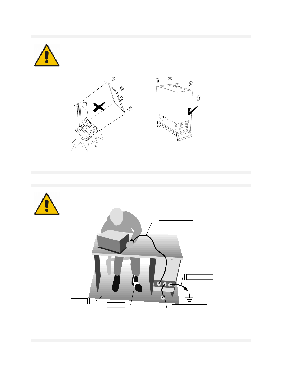
Safety Instructions
WARNING
Danger of injuries
When removing the rear feet, the unit can slip out of the cabinet.
Put the unit onto the front handles, before removing the rear feet and taking off the
cabinet. Thus the risk of personal injuries and damages to the unit is avoided.
When mounting the cabinet take care not to pen in the fingers. Also pay attention not
to damage or pull off cables. Screw the rear feet back on immediately after mounting
the cabinet. Do not move the unit with the rear feet missing.
ATTENTION
To avoid damage of electronic components, the operational site must be protected against
electrostatic discharge (ESD).
Wrist strap with cord
Building ground
Floor mat
Heel strap
Ground connection
of operational site
The following two methods of ESD protection may be used together or separately:
• Wrist strap with cord to ground connection
• Conductive floor mat and heel strap combination
1171.0000.22 E-1
Page 16

Page 17

DIN EN ISO 9001 : 2000
DIN EN 9100 : 2003
DIN EN ISO 14001 : 1996
DQS REG. NO 001954 QM/ST UM
Certified Quality System
Sehr geehrter Kunde,
Sie haben sich für den Kauf eines
Rohde & Schwarz-Produktes entschieden. Hiermit erhalten Sie ein nach
modernsten Fertigungsmethoden
hergestelltes Produkt. Es wurde nach
den Regeln unseres Managementsystems entwickelt, gefertigt und
geprüft.
Das Rohde & Schwarz Managementsystem ist zertifiziert nach:
DIN EN ISO 9001:2000
DIN EN 9100:2003
DIN EN ISO 14001:1996
Dear Customer,
you have decided to buy a Rohde &
Schwarz product. You are thus assured of receiving a product that is
manufactured using the most modern
methods available. This product was
developed, manufactured and tested
in compliance with our quality management system standards.
The Rohde & Schwarz quality management system is certified according to:
DIN EN ISO 9001:2000
DIN EN 9100:2003
DIN EN ISO 14001:1996
Cher Client,
vous avez choisi d‘acheter un produit
Rohde & Schwarz. Vous disposez
donc d‘un produit fabriqué d‘après
les méthodes les plus avancées. Le
développement, la fabrication et les
tests respectent nos normes de gestion qualité.
Le système de gestion qualité de
Rohde & Schwarz a été homologué
conformément aux normes:
DIN EN ISO 9001:2000
DIN EN 9100:2003
DIN EN ISO 14001:1996
QUALITÄTSZERTIFIKAT CERTIFICATE OF QUALITY CERTIFICAT DE QUALITÉ
1171.0200. 11- 01.00
Page 18

Page 19

Spare Parts Express Service
Phone: +49 89 4129 - 12465
Fax: +49 89 41
E-mail:werner.breidling@rsd.rohde-schwarz.com
In case of urgent spare parts requirements for this Rohde &
Schwarz unit, please contact our spare parts express
service.
Outside business hours, please leave us a message or
send a fax or e-mail. We shall contact you promptly.
29 - 13306
1007.9016
Page 20

Page 21

Customer Support
Technical support – where and when you need it
For quick, expert help with any Rohde & Schwarz equipment, contact one of our
Customer Support Centers. A team of highly qualified engineers provides telephone
support and will work with you to find a solution to your query on any aspect of the
operation, programming or applications of Rohde & Schwarz equipment.
Up-to-date information and upgrades
To keep your Rohde & Schwarz equipment always up-to-date,
please subscribe to our electronic newsletter at
http://www.rohde-schwarz.com/www/response.nsf/newsletterpreselection
or request the desired information and upgrades via email from your Customer Support
Center (addresses see below).
Feedback
We want to know if we are meeting your support needs. If you have any comments
please email us and let us know CustomerSupport.Feedback@rohde-schwarz.com.
USA & Canada
East Asia
Rest of the World
Monday to Friday (except US public holidays)
8:00 AM – 8:00 PM
Tel. from USA 888-test-rsa (888-837-8772) (opt 2)
From outside USA +1 410 910 7800 (opt 2)
Fax +1 410 910 7801
E-mail Customer.Support@rsa.rohde-schwarz.com
Monday to Friday (except Singaporean public holidays)
8:30 AM – 6:00 PM Singapore Time (SGT)
Tel. +65 6 513 0488
Fax +65 6 846 1090
E-mail Customersupport.asia@rohde-schwarz.com
Monday to Friday (except German public holidays)
08:00 – 17:00 Central European Time (CET)
Tel. from Europe +49 (0) 180 512 42 42
From outside Europe +49 89 4129 13776
Fax +49 (0) 89 41 29 637 78
Eastern Standard Time (EST)
1171.0200.22-01.00
E-mail CustomerSupport@rohde-schwarz.com
Page 22

Page 23

12
Address List
Headquarters, Plants and Subsidiaries
Headquarters
ROHDE& SCHWARZ GmbH & Co. KG
Mühldorfstraße 15 · D-81671 München
P.O.Box 80 14 69 · D-81614 München
Plants
ROHDE& SCHWARZ Messgerätebau GmbH
Riedbachstraße 58 · D-87700 Memmingen
P.O.Box 16 52 · D-87686 Memmingen
ROHDE& SCHWARZ GmbH & Co. KG
Werk Teisnach
Kaikenrieder Straße 27 · D-94244 Teisnach
P.O.Box 11 49 · D-94240 Teisnach
ROHDE& SCHWARZ závod
Vimperk, s.r.o.
Location Spidrova 49
CZ-38501 Vimperk
ROHDE& SCHWARZ GmbH & Co. KG
Dienstleistungszentrum Köln
Graf-Zeppelin-Straße 18 · D-51147 Köln
P.O.Box 98 02 60 · D-51130 Köln
Subsidiaries
R&S BICK Mobilfunk GmbH
Fritz-Hahne-Str. 7 · D-31848 Bad Münder
P.O.Box 20 02 · D-31844 Bad Münder
ROHDE& SCHWARZ FTK GmbH
Wendenschloßstraße 168, Haus 28
D-12557 Berlin
ROHDE& SCHWARZ SIT GmbH
Am Studio 3
D-12489 Berlin
R&S Systems GmbH
Graf-Zeppelin-Straße 18
D-51147 Köln
GEDIS GmbH
Sophienblatt 100
D-24114 Kiel
HAMEG Instruments GmbH
Industriestraße 6
D-63533 Mainhausen
Fax +49 (89) 41 29-121 64
info.rs@rohde-schwarz.com
Phone +49 (83 31) 1 08-0
info.rsmb@rohde-schwarz.com
Phone +49 (99 23) 8 50-0
info.rsdts@rohde-schwarz.com
Phone +420 (388) 45 21 09
Fax +49 (22 03) 49 51-229
info.rsdc@rohde-schwarz.com
service.rsdc@rohde-schwarz.com
Phone +49 (50 42) 9 98-0
info.bick@rohde-schwarz.com
Phone +49 (30) 658 91-122
info.ftk@rohde-schwarz.com
info.sit@rohde-schwarz.com
Phone +49 (22 03) 49-5 23 25
Fax +49 (22 03) 49-5 23 36
info.rssys@rohde-schwarz.com
Phone +49 (431) 600 51-0
Phone +49 (89) 41 29-0
+49 (83 31) 1 08-1124
Fax +49 (99 23) 8 50-174
Fax +420 (388) 45 21 13
Phone +49 (22 03) 49-0
Fax +49 (50 42) 9 98-105
Fax +49 (30) 655 50-221
Phone +49 (30) 658 84-0
Fax +49 (30) 658 84-183
Fax +49 (431) 600 51-11
sales@gedis-online.de
Phone +49 (61 82) 800-0
Fax +49 (61 82) 800-100
info@hameg.de
Locations Worldwide
Please refer to our homepage: www.rohde-schwarz.com
◆ Sales Locations
◆ Service Locations
◆ National Websites
12
1171.0200.42-02.00
Page 24

Page 25

Service and Repair R&S FSP
Contents of Manuals for Spectrum Analyzer R&S FSP
Service Manual - Instrument
The service manual - instrument informs on how to check compliance with rated specifications, on
instrument function, repair, troubleshooting and fault elimination. It contains all information required
for repairing the R&S FSP by the replacement of modules.
The service manual comprises four chapters and an annex (chapter 5) containing the R&S FSP circuit
documentation:
Chapter 1 provides all the information necessary to check for compliance with rated specifi-
cations. The required test equipment is included, too.
Chapter 2 describes the manual adjustment of the calibration source and of the frequency
accuracy as well as the automatic adjustment of individual module data following
module replacement.
Chapter 3 describes the design as well as simple measures for repair and fault
diagnosis, in particular, the replacement of modules.
Chapter 4 contains information on the extension and modification by installing
instrument software and retrofitting options.
Chapter 5 describes the shipping of the instrument and ordering of spare parts and contains
spare parts lists and exploded views.
Operating Manual
In the operating manual you will find information about the technical specifications, the controls and
connectors on the front and rear panel, necessary steps for putting the instrument into operation, the
basic operating concept, manual and remote control.
For introduction typical measurement tasks are explained in detail using the functions of the user interface and program examples.
The operating manual further provides hints on preventive maintenance and fault
diagnosis by means of warnings and error messages output by the unit.
1164.4556.82 0.1 E-2
Page 26

R&S FSP Manuals
Service and Repair
Please contact your Rohde & Schwarz support center or our spare parts express service if you need
service or repair of your equipment or to order spare parts and modules.
The list of the Rohde & Schwarz representatives and the address of our spare parts express service are
provided at the beginning of this service manual.
We require the following information in order to answer your inquiry fast and correctly and to decide
whether the warranty still applies for your instrument:
• Instrument model
• Serial number
• Firmware version
• Detailed error description in case of repair
• Contact partner for checkbacks
Rohde & Schwarz offers the following calibrations:
• Calibration on R&S-type test systems. The calibration documentation meets the requirements of
the quality management system ISO 9000.
• Calibration at an R&S calibration center approved by the German Calibration Service (DKD).
The calibration documentation consists of the DKD calibration certificate.
Refer to Chapter 5 for a detailed description on shipping of the instrument and ordering of spare parts.
1164.4556.82 0.2 E-2
Page 27

R&S FSP Contents - Performance Test
Contents - Chapter 1 "Performance Test"
1 Performance Test................................................................................................ 1.1
Test Instructions...............................................................................................................................1.1
Measurement Equipment and Accessories ...................................................................................1.1
Performance Test R&S FSP.............................................................................................................1.4
Checking Reference Frequency Accuracy ...............................................................................1.4
Checking Immunity to Interference ..........................................................................................1.4
1st IF Image Frequency Rejection .................................................................................1.5
2nd IF Image Frequency Rejection................................................................................1.5
3rd IF Image Frequency Rejection.................................................................................1.5
1st IF Rejection ..............................................................................................................1.6
2nd IF Rejection .............................................................................................................1.6
Checking Nonlinearities............................................................................................................1.7
Third Order Intercept Point ............................................................................................1.7
Checking IF Filters ...................................................................................................................1.8
Checking Bandwidth Switching Level Accuracy.............................................................1.8
Checking Bandwidth ......................................................................................................1.9
Checking Shape Factor .................................................................................................1.9
Checking Noise Display .........................................................................................................1.10
Checking Level Accuracy and Frequency Response.............................................................1.11
Checking Display Linearity .....................................................................................................1.14
Checking RF Attenuator .........................................................................................................1.16
Checking Reference Level Switching (IF Gain) .....................................................................1.17
Checking Phase Noise ...........................................................................................................1.19
Performance Test Option TV and RF Trigger: R&S FSP-B6 ......................................................1.21
Checking RF Trigger ..............................................................................................................1.21
Checking TV Trigger ..............................................................................................................1.21
Performance Test Option Tracking Generator – R&S FSP-B9...................................................1.22
Checking Output Level ...........................................................................................................1.22
Checking Frequency Response .............................................................................................1.23
Checking Modulation..............................................................................................................1.24
Checking I/Q Modulation..............................................................................................1.24
Checking Amplitude Modulation ..................................................................................1.25
Checking Frequency Modulation..................................................................................1.26
Performance Test Option WCDMA Demodulation Hardware – R&S FSP-B15 .........................1.27
Checking Comb Line Level ....................................................................................................1.27
Performance Test Option Electronic Attenuator- R&S FSP-B25 ..............................................1.28
Checking Noise Display with Preamplifier (B25) ....................................................................1.28
Checking Level Accuracy and Frequency Response with Preamplifier .................................1.29
Checking Frequency Response with Electronic Attenuator ...................................................1.32
Checking Nonlinearities with Electronic Attenuator................................................................1.34
Third Order Intercept....................................................................................................1.34
Checking RF Attenuator (with Option B25) ............................................................................1.35
Checking Electronic Attenuator Accuracy ..............................................................................1.36
1164.4556.82 I-1.1 E-1
Page 28

Contents - Performance Test R&S FSP
Performance Test Option External Mixing R&S FSP-B21 ..........................................................1.37
Checking LO-Levels ...............................................................................................................1.37
Checking the input LO
Checking the input IFin (3-Port-Mixers) ..................................................................................1.38
Checking the bias supply .......................................................................................................1.39
Performance Test Report R&S FSP ..............................................................................................1.40
Performance Test Report Option R&S FSP-B6 ...........................................................................1.53
Performance Test Report Option R&S FSP-B9 ...........................................................................1.54
Performance Test Report Option R&S FSP-B15 .........................................................................1.55
Performance Test Report Option R&S FSP-B25 .........................................................................1.56
Performance Test Report Option R&S FSP-B21 .........................................................................1.62
/ IFin (2-Port-Mixers) .......................................................................1.38
out
1164.4556.82 I-1.2 E-3
Page 29

R&S FSP Measurement Equipment
1 Performance Test
Test Instructions
• The rated specifications of the analyzer are tested after a warm-up time of at least 15 minutes and
overall calibration. Only in this case can compliance with the specified data be ensured. Start of
overall adjustment: [CAL : CAL TOTAL]
• Unless specified otherwise, all measurements will be performed with external reference frequency.
• Values specified in the following sections are not ensured. Only the technical specifications of the
data sheet are binding.
• The values specified in the data sheet are the ensured limits. Due to measurement errors, these
limits must be extended by the tolerance of the measurement equipment used in this performance
test.
• Inputs for settings during measurements are shown as follows:
[<KEY>] Press a key on the front panel, e.g. [ SPAN ] .
[<SOFTKEY>] Press a softkey, e.g. [ MARKER -> PEAK ].
[<nn unit>] Enter a value and terminate by entering the unit, e.g. [ 12 kHz ]
Successive entries are separated by [:], e.g. [ BW : RES BW MANUAL : 3 kHz ]
Measurement Equipment and Accessories
Item Type of
equipment
1 Frequency
counter
2 Signal generator R&S FSP 3: 10 MHz to 10 GHz
3 Signal generator 1 MHz to 3 GHz
4 Signal generator 498 MHz
Specifications recommended Equipment
Accuracy < 1x10⁻⁹,
Frequency range up to 10 MHz
R&S FSP 7: 10 MHz to 10 GHz
R&S FSP 13: 10 MHz to 13.6 GHz
R&S FSP 30: 10 MHz to 30 GHz
R&S FSP 40: 1 MHz to 40 GHz
Phase noise at 498 MHz:
< -100 dBc/Hz @ 100 Hz
< -115 dBc/Hz @ 1 kHz
< -127 dBc/Hz @ 10 kHz
< -130 dBc/Hz @ 100 kHz
< -142 dBc/Hz @ 1 MHz
Phase noise at 498 MHz:
< -130 dBc/Hz @ 100 kHz
< -142 dBc/Hz @ 1 MHz
recommended
Advantest
R5361B
with option 23
R&S SMP02
R&S SMP02
R&S SMP02
R&S SMP04
R&S SMP04
R&S SMA100A
with options
R&S
SMA-B103,
R&S SMA-B22
Alternative
equipment
HP 53132A
with option
012 (Agilent)
HP 63620 B
HP 63620 B
HP 63620 B
HP 83640 B
HP 63640 B
(Agilent)
HP 8664 A
OPT 004
(Agilent)
HP 8663 A
(Agilent)
Use
Frequency accuracy of
reference oscillator
Immunity to interference
Third order intercept
Frequency response
Calibration source
128 MHz
2nd order harmonic dist.
Third order intercept
IF filters
Frequency response
Display linearity
RF attenuator
Reference level switching
Phase noise
RF trigger
Phase noise (only if used
with HP 8664 A)
1164.4556.82 1.1 E-1
Page 30

Measurement Equipment R&S FSP
Item Type of
equipment
5 Signal generator R&S FSP 07: 10 MHz to 7 GHz
6 Power splitter
2-resistor design
7
50 termination
8 Power meter R&S NRVD HP 483A
9 Power sensor 1 MHz to 3 GHz
10 Power sensor
11 Step attenuator Variable attenuation
12 Fixed attenuator
(2 x)
14 N cable Attenuation < 0.2 dB to 3 GHz TG output level
15 Spectrum
analyzer
16 Arbitrary
waveform
generator
Specifications recommended Equipment
R&S FSP 13: 10 MHz to 13.6 GHz
R&S FSP 30: 10 MHz to 30 GHz
R&S FSP 40: 1 MHz to 40 GHz
R&S FSP 03: 1 MHz to 3 GHz
R&S FSP 07: 10 MHz to 7 GHz
R&S FSP 13: 10 MHz to 13.6 GHz
R&S FSP 30: 10 MHz to 30 GHz
R&S FSP 40: 10 MHz to 40 GHz
Level imbalance
1 MHz to 3 GHz 0.15 dB
3 GHz to 7 GHz 0.2 dB
7 GHz to 13.6 GHz 0.25 dB
13.6 GHz to 40 GHz 0.4 dB
R&S FSP 03: to 3 GHz
R&S FSP 07: to 7 GHz
R&S FSP 13: to 13.6 GHz
R&S FSP 30: to 30 GHz
R&S FSP 40: to 40 GHz
RSS 0.8%
Meter noise 20 pW
RSS referenced to indic. power:
1 MHz to 1 GHz 1.5 %
1 GHz to 7 GHz 2 %
7 GHz to 13.6 GHz 3.5 %
13.6 GHz to 30 GHz 4 %
R&S FSP 03: 10 MHz to 3 GHz
R&S FSP 07: 10 MHz to 7 GHz
R&S FSP 13: 10 MHz to 13.6 GHz
R&S FSP 30: 10 MHz to 30 GHz
R&S FSP 40: 10 MHz to 40 GHz
0 dB to 100 dB, 1 dB steps
Attenuation accuracy
< 0.1 dB (f = 128 MHz)
Fixed attenuation 10 dB
R&S FSP 03: 10 MHz to 3 GHz
R&S FSP 07: 10 MHz to 7 GHz
R&S FSP 13: 10 MHz to 13.6 GHz
R&S FSP 30: 10 MHz to 30 GHz
R&S FSP 40: 10 MHz to 40 GHz
Frequency range to 3 GHz R&S FSP 3 E4404B
Frequency range to 10 MHz
2 sinusoidal signals with 90 deg.
phase difference
recommended
R&S SMP02
R&S SMP02
R&S SMP04
R&S SMP04
HP 11667A
(Agilent)
HP 11667C
+ adapter to K
(Agilent)
RNA
RNA
Wiltron 28S50
Wiltron 28K50
Wiltron 28K50
R&S NRV-Z4 HP 8482 A
R&S NRV-Z4
R&S NRV-Z2
R&S NRV-Z2
R&S NRV-Z55
R&S NRV-Z55
R&S RSP 11713A with
DNF
DNF
Wiltron
43KB-10
Wiltron
43KC-10
Wiltron
43KC-10
R&S ADS 33220A with
Alternative
equipment
HP 63620 B
HP 63620 B
HP 83640 B
HP 83640 B
(Agilent)
Third order intercept
85138A
(Agilent)
(Agilent)
(Agilent)
HP 8487 A
(Agilent)
8494G and
8496G
(Agilent)
8490D-010
(Agilent)
ESA-E
(Agilent)
option 001
(Agilent)
(2 units)
Use
Third order intercept
Frequency response
Noise display
Frequency response
Frequency response
Frequency response
Reference level switching
display linearity
RF attenuator
Third order intercept
TG modulation
TG modulation
1164.4556.82 1.2 E-1
Page 31

R&S FSP Measurement Equipment
Item Type of
equipment
17 Voltmeter
(2 units)
18 TV signal source Checking the TV trigger
19 Power sensor Frequency range
20 Fixed attenuator fixed attenuation 10 dB
21 DC-current
meter
Specifications recommended Equipment
DC and AC voltages R&S URE 34401A
7.0 GHz up to 15.5 GHz
max. power input
+ 23 dBm
RSS referred to indicated Power
2.5 %
up to 18 GHz
Max. current 50 mA
uncertainty +/- 0.01 mA
recommended
R&S NRV-Z55
Wiltron
41KA-10
B21: mixer bias current
Alternative
equipment
(Agilent)
8490D-010
(Agilent)
Use
TG modulation
B21: LO output power
B9: frequency response
B21: LO output power
source
1164.4556.82 1.3 E-1
Page 32

Performance Test R&S FSP
Performance Test R&S FSP
Checking Reference Frequency Accuracy
Test equipment:
Test setup: Connect frequency counter to 10 MHz reference output of the R&S
R&S FSP settings:
Measurement: Measure frequency with frequency counter.
Note:
Frequency counter (refer to "Measurement Equipment", item 1):
Accuracy < 1x10
Frequency range up to 10 MHz
FSP (rear panel).
- [SETUP : REFERENCE INT / EXT ]
Toggle to internal reference (INT).
Nominal frequency:
Model without OCXO (option R&S FSP-B4) .........10 MHz ± 10 Hz
Model with OCXO (option R&S FSP-B4) ............. 10 MHz ± 1 Hz
The frequency of the reference oscillator can be adjusted by means of
a service function (refer to chapter "Adjustment").
-9
Checking Immunity to Interference
Test equipment:
Signal generator (refer to "Measurement Equipment", item 2):
Frequency range R&S FSP 3: 10 MHz to 10 GHz
R&S FSP 7: 10 MHz to 10 GHz
R&S FSP 13: 10 MHz to 13.6 GHz
R&S FSP 30: 10 MHz to 30 GHz
R&S FSP 40: 10 MHz to 40 GHz
Maximum level -10 dBm
Test setup: Connect RF output of the signal generator to RF input.
Signal generator settings:
R&S FSP settings:
1164.4556.82 1.4 E-1
Level: Adjust the output level of signal generator for an RF input
level of -10 dBm.
- [ PRESET ]
- [ AMPT : RF ATTEN MANUAL : 0 dB ]
- [ AMPT : REF LEVEL : -30 dBm ]
- [ SPAN : 100 kHz ]
- [ BW : RES BW MANUAL : 3 kHz ]
Page 33

R&S FSP Performance Test
1st IF Image Frequency Rejection
Additional signal generator
settings:
- Frequency f
+ 6952.8 MHz
in
Additional R&S FSP settings: - [ FREQ : CENTER : {f
Refer to "Performance Test Report" table for values of f
Measurement:
Set marker to peak of signal:
} ]
in
.
in
[ MKR : PEAK ]
Evaluation: The image frequency rejection is the difference between the output
level of the signal generator and the level reading of marker 1 (L
Image frequency rejection = -10 dBm – L
dis
dis
2nd IF Image Frequency Rejection
Additional signal generator
settings:
- Frequency f
Additional R&S FSP settings: - [ FREQ : CENTER : {f
Refer to "Performance Test Report" table for values of f
Measurement:
Set marker to peak of signal:
[ MKR : PEAK ]
Evaluation: The image frequency rejection is the difference between the output
level of the signal generator and the level reading of marker 1 (L
Image frequency rejection = –10 dBm – L
+ 808.8 MHz
in
} ]
in
dis
.
in
dis
):
):
3rd IF Image Frequency Rejection
Additional signal generator
settings:
- Frequency f
Additional R&S FSP settings: - [ FREQ : CENTER : {f
Refer to "Performance Test Report" table for values of f
Measurement:
Set marker to peak of signal:
[ MKR : PEAK ]
Evaluation: The image frequency rejection is the difference between the output
level of the signal generator and the level reading of marker 1 (L
Image frequency rejection = –10 dBm – L
1164.4556.82 1.5 E-1
+ 40.8 MHz
in
} ]
in
dis
.
in
):
dis
Page 34

Performance Test R&S FSP
1st IF Rejection
Additional signal generator
settings:
- Frequency 3476.4 MHz
Additional R&S FSP settings: - [ FREQ : CENTER : {f
Refer to "Performance Test Report" table for values of f
Measurement:
Set marker to peak of signal:
} ]
in
.
in
- [ MKR : PEAK ]
Evaluation: The IF rejection is the difference between the output level of the signal
generator and the level reading of marker 1 (L
IF rejection = –10 dBm – L
dis
dis
):
2nd IF Rejection
Additional signal generator
settings:
Additional R&S FSP settings: - [ FREQ : CENTER : {f
- Frequency 404.4 MHz
} ]
in
Refer to "Performance Test Report" table for values of f
.
in
Measurement:
Set marker to peak of signal:
- [ MKR : PEAK ]
Evaluation: The IF rejection is the difference between the output level of the signal
generator and the level reading of marker 1 (L
IF rejection = –10 dBm – L
dis
dis
):
1164.4556.82 1.6 E-1
Page 35

R&S FSP Performance Test
Checking Nonlinearities
Third Order Intercept Point
Test equipment:
- 2 signal generators
R&S FSP 3: Refer to "Measurement Equipment", items 2 & 3.
R&S FSP 7/13/30/40: Refer to "Measurement Equipment",
items 2 & 5.
Frequency range:
R&S FSP 3: 10 MHz to 3 GHz
R&S FSP 7: 10 MHz to 7 GHz
R&S FSP 13: 10 MHz to 13.6 GHz
R&S FSP 30: 10 MHz to 30 GHz
R&S FSP 40: 10 MHz to 40 GHz
Maximum level 0 dBm
- 2 attenuators (refer to "Measurement Equipment", item 12)
Attenuation a
= 10 dB
ATT
Frequency range
R&S FSP 3: 10 MHz to 3 GHz
R&S FSP 7: 10 MHz to 7 GHz
R&S FSP 13: 10 MHz to 13.6 GHz
R&S FSP 30: 10 MHz to 30 GHz
R&S FSP 40: 10 MHz to 40 GHz
- Power splitter (refer to "Measurement Equipment", item 6)
Frequency range
R&S FSP 3: 10 MHz to 3 GHz
R&S FSP 7: 10 MHz to 7 GHz
R&S FSP 13: 10 MHz to 13.6 GHz
R&S FSP 30: 10 MHz to 30 GHz
R&S FSP 40: 10 MHz to 40 GHz
Decoupling > 12 dB
Test setup: Connect RF outputs of the signal generators via 10 dB attenuators
to the inputs of the power splitter.
Connect output of the power splitter to RF input of the R&S FSP.
Signal generator settings
(both generators):
- Frequency: Generator 1 f
Generator 2 fg2 = fin + 50 kHz
= fin 50 kHz
g1
Refer to "Performance Test Report" table for values of f
.
in
Adjust the output level of signal generators for an input level at the
R&S FSP of -20 dBm.
R&S FSP settings:
- [ PRESET ]
- [ AMPT : RF ATTEN MANUAL : 0 dB ]
- [ AMPT : -10 dBm ]
- [ SPAN : 500 kHz ]
- [ BW : RES BW MANUAL : 3 kHz ]
Measurement:
Evaluation:
- [ FREQ : CENTER : {f
Refer to "Performance Test Report" table for values of f
[ MKR FCTN : TOI ]
The third order intercept point (TOI) referenced to the input signal is
} ]
in
.
in
displayed in the marker field by the reading [TOI].
1164.4556.82 1.7 E-1
Page 36

Performance Test R&S FSP
Checking IF Filters
Test equipment:
Signal generator (refer to "Measurement Equipment", item 3):
Frequency 128 MHz
Level 0 dBm
Test setup: Connect RF output of the signal generator to RF input of the
R&S FSP.
Checking Bandwidth Switching Level Accuracy
Reference measurement (RBW 10 kHz)
Signal generator settings:
R&S FSP settings:
Reference measurement:
- Frequency:
- Level: -30 dBm
128 MHz
- [ PRESET ]
- [ AMPT : -20 dBm ]
- [ AMPT : RF ATTEN MANUAL : 10 dB ]
- [ FREQ : CENTER : 128 MHz ]
- [ SPAN : 5 kHz ]
- [ TRACE : DETECTOR : RMS ]
- [ BW : RBW MANUAL : 10 : kHz ]
Set marker to peak of signal:
- [ MKR : PEAK ]
Checking level accuracy
R&S FSP settings:
Note:
Measurement:
Evaluation:
Set reference to peak of signal:
- [ MKR : REFERENCE FIXED ]
- [ SPAN : {0.5 x RBW} ]
- [ BW : RBW MANUAL : {RBW} : ENTER]
To check the FFT filter, the resolution bandwidth has to be set manually
to FFT mode.
-[ BW : BW MODE : FFT ]
Set marker to peak of signal:
- [ MKR : PEAK ]
The level difference is displayed in the marker field by the reading
´Delta [T1 FXD] {xxx} dB´.
1164.4556.82 1.8 E-1
Page 37

R&S FSP Performance Test
Checking Bandwidth
Signal generator settings:
- Frequency:
- Level: -10 dBm
R&S FSP settings:
- [ PRESET ]
- [ AMPT : RF ATTEN MANUAL : 10 dB ]
- [ AMPT : 0 dBm ]
- [ FREQ : CENTER : 128 MHz ]
- [ BW : COUPLING RATIO : SPAN/RBW MANUAL : 3 : ENTER ]
Determine 3 dB bandwidth:
- [ MKR FCTN : N DB DOWN : 3 dB ]
- [ SPAN : {3 x RBW} ]
Refer to "Performance Test Report" table for values of RBW.
Note:
To check the 10 MHz filter, the resolution bandwidth has to be set
manually to 10 MHz. All other bandwidths will be set automatically by
changing the span.
-[ BW : RES BW MANUAL : 10 MHz ]
Measurement:
- [ MKR : PEAK ]
The 3 dB bandwidth is displayed by the reading ´BW {bandwidth}´.
Checking Shape Factor
128 MHz
Note: To check the shape factor, you need to know the values of the 3 dB bandwidth . Please check
these values before performing this measurement.
Signal generator settings:
- Frequency:
128 MHz
- Level: 0 dBm
R&S FSP settings:
- [ PRESET ]
- [ AMPT : RF ATTEN MANUAL : 10 dB ]
- [ AMPT : 0 dBm ]
- [ FREQ : CENTER : 128 MHz ]
- [ BW : COUPLING RATIO : SPAN/RBW MANUAL : 20 ENTER ]
- [ BW : COUPLING RATIO : RBW/VBW NOISE [10] ]
- [ MKR FCTN : N DB DOWN : 60 dB ]
- [ SPAN : {20 x RBW} ]
Refer to "Performance Test Report" table for values of RBW.
Note:
To check the 10 MHz filter, the resolution bandwidth has to be set
manually to 10 MHz. All other bandwidths will be set automatically by
changing the span.
-[ BW : RES BW MANUAL : 10 MHz ]
Measurement:
- [ MKR : PEAK ]
The 60 dB bandwidth is displayed by the reading ´BW {bandwidth}´.
Evaluation:
The shape factor is calculated by BW (60 dB) / BW (3 dB).
1164.4556.82 1.9 E-1
Page 38

Performance Test R&S FSP
Checking Noise Display
Test equipment:
Test setup:
R&S FSP settings:
Measurement:
Evaluation:
50 termination (refer to "Measurement Equipment", item 7)
Frequency range R&S FSP 3: to 3 GHz
R&S FSP 7: to 7 GHz
R&S FSP 13: to 13.6 GHz
R&S FSP 30: to 30 GHz
R&S FSP 40: to 40 GHz
Terminate the RF input of the R&S FSP with 50 .
- [ PRESET ]
- [ AMPT : RF ATTEN MANUAL : 0 dB ]
- [ SPAN : 0 Hz ]
- [ BW: RES BW MANUAL : 10 Hz ]
- [ BW : VIDEO BW MANUAL : 1 Hz ]
- [ BW : SWEEP TIME MANUAL : 0.1 s ]
- [ TRACE 1 : AVERAGE ]
- [ TRACE 1 : SWEEP COUNT : 30 ENTER ]
- [ AMPT : {RefLev} ]
- [ FREQ : CENTER : {f
} ]
n
Refer to table below for values of RefLev.
Refer to "Performance Test Report" table for values of f
.
n
Set marker to peak:
- [ MKR : PEAK ]
The noise level is displayed by the level reading of marker 1.
Frequency
RefLev
< 10 kHz < 100 kHz < 1 MHz < 10 MHz > 10 kHz
-10 dBm -20 dBm -30 dBm -60 dBm -60 dBm
1164.4556.82 1.10 E-1
Page 39

R&S FSP Performance Test
Checking Level Accuracy and Frequency Response
Test equipment:
- Signal generator:
R&S FSP 3: Refer to "Measurement Equipment", item 3.
R&S FSP 7/13/30:Refer to "Measurement Equipment", items 3 & 4.
Frequency range R&S FSP 3: 1 MHz to 3 GHz
R&S FSP 7: 1 MHz to 7 GHz
R&S FSP 13: 1 MHz to 13.6 GHz
R&S FSP 30: 1 MHz to 30 GHz
R&S FSP 40: 1 MHz to 40 GHz
Maximum level 0 dBm
- Power meter (refer to "Measurement Equipment", item 8)
- Power sensor:
R&S FSP 3: Refer to "Measurement Equipment", item 9.
R&S FSP 7/13/30: Refer to "Measurement Equipment",
items 9 & 10.
Frequency range R&S FSP 3: 1 MHz to 3 GHz
R&S FSP 7: 1 MHz to 7 GHz
R&S FSP 13: 1 MHz to 13.6 GHz
R&S FSP 30: 1 MHz to 30 GHz
R&S R&S FSP 40: 1 MHz to 40 GHz
Maximum power P
100 UW
max
RSS referenced to indicated power
1 MHz to 1 GHz 1.5 %
1 GHz to 7 GHz 2 %
7 GHz to 13.6 GHz 3.5 %
13.6 GHz to 40 GHz 4 %
Impedance Z = 50
- Power splitter (refer to "Measurement Equipment", item 6)
Frequency range R&S FSP 3: 1 MHz to 3 GHz
R&S FSP 7: 1 MHz to 7 GHz
R&S FSP 13: 1 MHz to 13.6 GHz
R&S FSP 30: 1 MHz to 30 GHz
R&S FSP 40: 1 MHz to 40 GHz
Level imbalance
1
) 1 MHz to 1 GHz 0.1 dB
1 GHz to 7 GHz 0.2 dB
7 GHz to 13.6 GHz 0.3 dB
13 GHz to 40 GHz 0.4 dB
1
) If a power splitter with higher level imbalance is used, correction
of the measured frequency response is recommended.
1164.4556.82 1.11 E-1
Page 40

Performance Test R&S FSP
Determining the level accuracy at 128 MHz
Test setup: Connect power sensor (item 9) to the power meter and execute
function ´ZERO´ when there is no signal applied to the power
sensor.
Connect power sensor to RF output of signal generator.
Signal generator settings:
Measurement: Determine output power of the signal generator with the power
R&S FSP settings:
- Frequency 128 MHz
- Level -30 dBm
meter.
Connect RF output of the signal generator to RF input of the
R&S FSP.
- [ PRESET ]
- [ AMPT : RF ATTEN MANUAL : 10 dB ]
- [ AMPT : -20 dBm ]
- [ SPAN : 30 kHz ]
- [ BW : RES BW MANUAL : 10 kHz ]
- [ TRACE : DETECTOR : RMS ]
- [ FREQ : CENTER : 128 MHz ]
Evaluation:
Set marker to peak of signal:
- [ MKR : PEAK ]
The difference between the signal levels measured with the power
meter and the R&S FSP (level reading of marker 1) reflects the
absolute level accuracy of the R&S FSP. It can be calculated as
follows:
Level accuracy
128MHz
= L
FSP
- L
powermeter
1164.4556.82 1.12 E-1
Page 41

R&S FSP Performance Test
Checking frequency response
Test setup: Connect RF output of signal generator to input of power splitter.
Connect output 1 of power splitter to power sensor / power meter.
Connect output 2 of divider to RF input of the R&S FSP.
Signal generator settings:
R&S FSP settings:
Reference measurement:
- Level 0 dBm
- Frequency 128 MHz
- [ PRESET ]
- [ AMPT : RF ATTEN MANUAL : 10 dB ]
- [ AMPT : 0 dBm ]
- [ SPAN : 100 kHz ]
- [ BW : RES BW MANUAL : 10 kHz ]
- [ TRACE : DETECTOR : RMS ]
- [ FREQ : CENTER : 128 MHz ]
Determine signal level L
powermeter
.
Set marker to peak of signal:
- [ MKR : PEAK ]
Measurement
Signal generator settings:
Power meter settings:
R&S FSP settings:
Evaluation:
The signal level L
Ref
128MHz
= L
is displayed by the level reading of marker 1.
FSP
- L
FSP
powermeter
- Frequency f
Refer to "Performance Test Report" table for values of f
Determine signal level L
fresp
powermeter
fresp
. To achieve higher accuracy,
.
compensating for the frequency response of the power sensor is
recommended.
- [ FREQ : CENTER : {f
Refer to "Performance Test Report" table for values of f
fresp
} ]
fresp
.
- Set marker to peak of signal:
- [ MKR : PEAK ]
The signal level L
is displayed by the level reading of marker 1.
FSP
The frequency response can be calculated as follows:
Frequency response = L
FSP
- L
powermeter
- Ref
128 MHz
1164.4556.82 1.13 E-1
Page 42

Performance Test R&S FSP
Checking Display Linearity
Test equipment:
- Signal generator (refer to "Measurement Equipment", item 3)
Frequency 128 MHz
Maximum level 10 dBm
- Step attenuator (refer to "Measurement Equipment", item 11)
Frequency 128 MHz
Attenuation 0 to 100 dB in 1 dB steps
Attenuation accuracy < 0.1 dB
1
) If a step attenuator with lower accuracy is used, correction
of the measured attenuation is recommended.
1
)
Test setup: Connect RF output of the signal generator to RF input of the
step attenuator.
Connect RF output of the step attenuator to RF input of the R&S
FSP.
Signal generator settings:
- Frequency 128 MHz
- Level +10 dBm
Step attenuator settings:
Attenuation 20 dB
R&S FSP settings:
- [ PRESET ]
- [ AMPT : RF ATTEN MANUAL : 10 dB ]
- [ AMPT : 0 dBm ]
- [ FREQ :CENTER : 128 MHz ]
- [ SPAN : 0 Hz ]
- [ TRACE : DETECTOR : RMS ]
1st measurement:
- [ BW : RES BW MANUAL : 300 Hz ]
2nd measurement:
- [ BW : RES BW MANUAL : 300 kHz ]
Reference measurement: Set marker to peak of signal:
- [ MKR : PEAK ]
Set reference to peak of signal:
- [ MKR : REFERENCE FIXED ]
Measurement
Step attenuator settings:
Attenuation {a
ATT
}
Refer to "Performance Test Report" table for values of a
Evaluation:
The difference between the level of the input signal of the R&S FSP
and the reference (about 10 dB below the reference level) is displayed
in the marker field by the reading ´Delta [T1 FXD]´.
ATT
.
1164.4556.82 1.14 E-1
Page 43

R&S FSP Performance Test
Alternative measurement
R&S FSP settings:
Reference measurement:
- [ PRESET ]
- [ AMPT : RF ATTEN MANUAL : 10 dB ]
- [ AMPT : 0 dBm ]
- [ FREQ : CENTER : 128 MHz ]
- [ SPAN : 0 Hz ]
- [ TRACE : DETECTOR : AV ]
- [ SWEEP: SWEEP TIME MANUAL: xx ms ]
Depending on the attenuation a
of the step attenuator, the sweep
ATT
time is set as follows:
a
Sweep time xx
ATT
a
50 dB 200 ms
ATT
50 dB < a
a
> 70 dB 2000 ms
ATT
70 dB 600 ms
ATT
[MEAS: TIME DOM POWER: MEAN ]
Note: The trace averaged across all test points is used for
better averaging of the test results.
1st measurement:
- [ BW : RES BW MANUAL : 300 Hz ]
2nd measurement:
- [ BW : RES BW MANUAL : 300 kHz ]
Read the test result for the reference measurement (mean value in the
marker output field).
Use the measured mean value as the reference:
[ MEAS : TIME DOM POWER: {right side menu}: Power Rel
Set Reference]
Measurement
Step attenuator settings:
Attenuation {a
ATT
}
Refer to "Performance Test Report" table for values of a
ATT
.
Evaluation: The difference between the level of the input signal of the R&S FSP
and the reference (approx. 10 dB below the reference level) is
displayed in the marker field by the reading ´Power [T1]´.
1164.4556.82 1.15 E-1
Page 44

Performance Test R&S FSP
Checking RF Attenuator
Test equipment:
Test setup:
Signal generator settings:
Step attenuator settings:
R&S FSP settings:
- Signal generator (refer to "Measurement Equipment", item 3)
Frequency 128 MHz
Maximum level 0 dBm
- Step attenuator (refer to "Measurement Equipment", item 11)
Frequency 128 MHz
Attenuation 0 to 80 dB in 10 dB steps
Attenuation accuracy < 0.1 dB
1
) If a step attenuator with lower accuracy is used, correction
of the measured attenuation is recommended.
1
)
Connect RF output of the signal generator to RF input of the step
attenuator.
Connect RF output of the step attenuator to RF input of the
R&S FSP.
- Frequency 128 MHz
- Level 0 dBm
Attenuation 70 dB
- [ PRESET ]
- [ FREQ : CENTER : 128 MHz ]
- [ SPAN : 500 Hz ]
- [ BW : RES BW MANUAL : 1 kHz ]
- [ TRACE : DETECTOR : RMS ]
- [ BW : VIDEO BW MANUAL : 100 Hz ]
- [ AMPT : RF ATTEN MANUAL : 10 dB ]
- [ AMPT : -30 dBm ]
Reference measurement: Set marker to peak of signal:
- [ MKR : PEAK ]
Set reference to peak of signal:
- [ MKR : REFERENCE FIXED ]
Measurement
Step attenuator settings:
Attenuation { 80 dB - a
FSP
Refer to table below for values of a
R&S FSP settings:
- [ AMPT : RF ATTEN MANUAL : { a
- [ AMPT : {-40 dBm + a
} dBm ]
FSP
- [ MKR : PEAK ]
Refer to table below for values of a
Evaluation:
The difference between the level of the input signal of the R&S FSP
and the reference (at 10 dB RF attenuation) is displayed in the marker
field by the reading ´Delta [T1 FXD]´.
a
ATT
a
FSP
Reference level
80 dB 70 dB 60 dB 50 dB 40 dB 30 dB 20 dB 10 dB
0 dB 10 dB 20 dB 30 dB 40 dB 50 dB 60 dB 70 dB
-40 dBm -30 dBm -20 dBm -10 dBm 0 dBm +10 dBm +20 dBm +30 dBm
}
ATT
FSP
FSP
.
} ]
, a
and reference level.
ATT
1164.4556.82 1.16 E-1
Page 45

R&S FSP Performance Test
Checking Reference Level Switching (IF Gain)
Test principle:
The IF gain of the R&S FSP can be switched from 0 to 50 dB by
changing the reference level at fixed RF attenuation. To prevent the IF
gain accuracy from being confused with the log amplifier accuracy, it
is determined by comparison using an external precision attenuator.
Test equipment:
- Signal generator (refer to "Measurement Equipment", item 3)
Frequency 128 MHz
Maximum level -10 dBm
- Step attenuator (refer to "Measurement Equipment", item 11)
Frequency 128 MHz
Attenuation 0 to 60 dB in 1 dB steps
Attenuation accuracy < 0.1 dB
1
) If a step attenuator with lower accuracy is used, correction
of the measured attenuation is recommended.
1
)
Test setup: Connect RF output of the signal generator to RF input of the step
attenuator.
Connect RF output of the step attenuator to RF input of the
R&S FSP.
Signal generator settings:
- Frequency 128 MHz
- Level -10 dBm
Step attenuator settings:
Attenuation 20 dB
R&S FSP settings:
- [ PRESET ]
- [ FREQ : CENTER : 128 MHz ]
- [ SPAN : 2 kHz ]
- [ BW : RES BW MANUAL : 1 kHz ]
- [ BW : VIDEO BW MANUAL : 100 Hz ]
- [ TRACE : DETECTOR : RMS ]
- [ AMPT : RF ATTEN MANUAL : 10 dB ]
- [ AMPT : -10 dBm ]
Reference measurement: Set marker to peak of signal:
- [ MKR : PEAK ]
Set reference to peak of signal:
- [ MKR : REFERENCE FIXED ]
1164.4556.82 1.17 E-1
Page 46

Performance Test R&S FSP
Measurement
Step attenuator settings:
Attenuation {a
ATT
}
Refer to table below for values of a
ATT
.
R&S FSP settings:
Evaluation:
10 dB gain steps:
a
ATT
Reference level
1 dB gain steps:
a
ATT
Reference level
-10 dBm
- [ AMPT : {reference level} dBm ]
Refer to table below for values of reference level.
- [ MKR : PEAK ]
The difference between the level of the input signal of the R&S FSP
and the reference (at 10 dB IF gain) is displayed in the marker field by
the reading ´Delta [T1 FXD]´.
10 dB 20 dB 30 dB 40 dB 50 dB 60 dB
0 dBm -10 dBm -20 dBm -30 dBm -40 dBm -50 dBm
20 dB 21 dB 22 dB 23 dB 24 dB 25 dB 26 dB 27 dB 28 dB 29 dB
-11 dBm -12 dBm -13 dBm -14 dBm -15 dBm -16 dBm -17 dBm -18 dBm -19 dBm
1164.4556.82 1.18 E-1
Page 47

R&S FSP Performance Test
Connect signal generator EXT REF output to the EXT REF input of
Checking Phase Noise
Test equipment:
Test setup: Connect RF output of the signal generator to RF input of the
Signal generator (refer to "Measurement Equipment", item 3)
Frequency 498 MHz
Level 0 dBm
Phase noise at 498 MHz: < -100 dBc/Hz @ 100 Hz
< -115 dBc/Hz @ 1 kHz
< -127 dBc/Hz @ 10 kHz
< -130 dBc/Hz @ 100 kHz
< -142 dBc/Hz @ 1 MHz
or
Signal generator (refer to "Measurement Equipment", item 3)
Frequency 498 MHz
Level 0 dBm
Phase noise at 498 MHz: < -100 dBc/Hz @ 100 Hz
< -115 dBc/Hz @ 1 kHz
< -127 dBc/Hz @ 10 kHz
and
Signal generator (refer to "Measurement Equipment", item 4)
Frequency 498 MHz
Level 0 dBm
Phase noise at 498 MHz: < -100 dBc/Hz @ 100 Hz
< -130 dBc/Hz @ 100 kHz
< -142 dBc/Hz @ 1 MHz
R&S FSP.
the R&S FSP.
Signal generator settings: - Frequency 498 MHz
- Level 0 dBm
1164.4556.82 1.19 E-1
Page 48

Performance Test R&S FSP
R&S FSP settings:
- [ PRESET ]
- [ FREQ : CENTER : 498 MHz ]
- [ AMPT : 0 dBm ]
- [ AMPT : RF ATTEN MANUAL : 10 dB ]
- [ SPAN : {span} ]
Depending on offset, refer to table below for values of span.
- [ BW : COUPLING RATIO : RBW/VBW NOISE[10] ]
- [ BW : RBW MANUAL : {RBW } ]
Depending on offset, refer to table below for values of RBW.
- [ TRACE 1 : AVERAGE ]
- [ SWEEP : SWEEP COUNT : 20 : ENTER ]
Activate phase noise marker:
- [MKR FCTN : PHASE NOISE ]
- [ FREQ : CENTER : {498 MHz + offset} ]
Refer to table below for values of offset.
- [ AMPT : {reference level} ]
Depending on offset, refer to table below for values of reference
level.
- [ AMPT : RF ATTEN MANUAL : {a
Depending on offset, refer to table below for values of a
FSP
} ]
FSP
.
Set phase noise marker
[ MKR : MARKER 2 : {offset} ]
Refer to table below for values of offset.
Note: Do not measure on a spurious signal.
Evaluation: The phase noise is displayed in the marker field by the reading
´Delta 2 [T1 PHN]´.
Phase noise measurement settings
Offset Span RBW Reference level a
100 Hz 20 Hz 10 Hz 0 dBm 10 dB
1 kHz 200 Hz 100 Hz 0 dBm 10 dB
10 kHz 2 kHz 300 Hz -10 dBm 10 dB
100 kHz 10 kHz 3 kHz -20 dBm 0 dB
1 MHz 100 kHz 30 kHz -20 dBm 0 dB
FSP
Note: To obtain a precise measurement of the phase noise at high offsets, the level used at the
R&S FSP input is 20 dB higher than the reference level. To reduce the measurement time,
the phase noise is measured with a small span around the frequency offset. This prevents
the R&S FSP from being overloaded.
1164.4556.82 1.20 E-1
Page 49

R&S FSP Performance Test
Performance Test Option TV and RF Trigger: R&S FSP-B6
Checking RF Trigger
Test equipment:
- Signal generator (refer to "Measurement Equipment", item 3)
Frequency 128 MHz
Test setup:
Connect test output of the signal generator to RF input of the R&S
FSP.
Signal generator settings: - Frequency 128 MHz
- Level - {L
GEN
}
- Modulation AM, 90%, 100 Hz
R&S FSP settings:
- [ PRESET ]
- [ AMPT: 0 dBm ]
- [ AMPT: RF ATTEN MANUAL : 10 dB ]
- [ FREQ: CENTER : 128 MHz ]
- [ SPAN: ZERO ]
- [ TRIG: RF POWER : {L
- [ SWEEP: SWEEPTIME MANUAL : 10 ms ]
- [ MARKER: 0 s ]
Measurement:
Set marker to sweep start:
- [ MKR : 0 s ]
Set trigger level L
and generator level L
TRG
trigger threshold using the marker.
Refer to "Performance Test Report" table for values of L
TRG
} ]
GEN
(L
GEN
= L
TRG
). Check
TRG
.
Checking TV Trigger
Test equipment:
Test setup:
R&S FSP settings:
Evaluation:
- TV signal source (e.g. TV antenna)
Connect the TV signal source to the RF input of the R&S FSP.
- [ PRESET]
- [ AMPT: RF ATTEN MANUAL : 0 dB ]
- [ AMPT: {L
- [ FREQ: CENTER : {f
TV
} ]
TV
} ]
- [ SPAN: ZERO ]
- [ SWEEP: SWEEP TIME MANUAL: 128 µs ]
- [ TRIG: NEXT: TV TRIG SETTINGS: HOR SYNC ]
- [ AMPT: RANGE LINEAR ]
The frequency f
The level L
TV
is the vision carrier frequency of the TV signal.
TV
is the vision carrier level.
Test lines 17 and 18 are displayed on the screen of the R&S FSP.
Note: A CCVS monitor can be connected to the CCVS IN/OUT
connector for checking the TV picture.
1164.4556.82 1.21 E-1
Page 50

Performance Test R&S FSP
Performance Test Option Tracking Generator – R&S FSP-B9
Checking Output Level
Test equipment:
Test setup:
R&S FSP settings:
Measurement:
- N cable (refer to "Measurement Equipment", item 14)
Frequency up to 3 GHz
Maximum attenuation < 0.2 dB
Connect tracking generator output to RF input of the R&S FSP.
- [ PRESET ]
- [ MODE NETWORK ]
- [ FREQ : CENTER : 128 MHz ]
- [ SPAN : 0 Hz ]
- [ BW : RES BW MANUAL : 1 kHz ]
- [ AMPT : RF ATTEN MANUAL : 10 dB ]
- [ AMPT : -0 dBm ]
- [ NETWORK : SOURCE POWER {level}]
{level} : 0 dBm; -5 dBm; -10 dBm; -15 dBm; -20 dBm; -25 dBm
Set marker to peak:
- [ MKR : PEAK ]
1164.4556.82 1.22 E-1
Page 51

R&S FSP Performance Test
Checking Frequency Response
Test equipment:
- N cable (refer to "Measurement Equipment", item 14)
- 10 dB attenuator (refer to "Measurement Equipment", item 20)
Frequency up to 3 GHz
Maximum attenuation < 0.2 dB
Test setup: Connect 10 dB attenuator to tracking generator output port. Connect
10 dB attenuator to RF input of the R&S FSP.
R&S FSP settings:
- [ PRESET ]
- [ NETWORK ]
- [ NETWORK : SOURCE POWER 0 dBm ]
- [ AMPT : RF ATTEN MANUAL : 20 dB ]
- [ AMPT : 0 dBm ]
- [ NETWORK : SOURCE POWER {level}]
{level} : 0 dBm; -10 dBm; -25 dBm
- [ BW : RES BW MANUAL : 1 kHz ]
- [ SWT : MANUAL : 2 s ]
Reference:
- [ FREQ : CENTER : 128 MHz ]
- [ SPAN : 0 Hz ]
Range 1:
- [ FREQ : START : 9 kHz ]
- [ FREQ : STOP : 100 kHz ]
Range 2:
- [ FREQ : START : 100 kHz ]
- [ FREQ : STOP : 1 MHz ]
- [ BW : RES BW MANUAL : 10 kHz ]
- [ SWT : AUTO ]
Range 3:
- [ FREQ : START : 1 MHz ]
- [ FREQ : STOP : 2 GHz ]
Range 4:
- [ FREQ : START : 2 GHz ]
- [ FREQ : STOP : 3 GHz ]
Measurement:
Reference:
Set Marker to 128 MHz (=Ref
128 MHz
).
All other ranges:
Set marker to peak:
- [ MKR : PEAK ] (=L
max
)
Set marker to minimum value:
Evaluation:
[ MKR : MIN PEAK ] (=L
Calculate frequency response:
Maximum = L
Minimum = L
max
min
- Ref
- Ref
128 MHz
128 MHz
min
)
1164.4556.82 1.23 E-1
Page 52

Performance Test R&S FSP
voltages in parallel via T pieces.
Checking Modulation
Checking I/Q Modulation
Test equipment:
Test setup with R&S ADS: Apply the I and Q outputs of ADS to the I and Q inputs of the
Test setup with 33220A: Apply the outputs of 33220A to the I and Q inputs of the analyzer.
Generator settings:
Spectrum analyzer settings:
- Arbitrary waveform generator (refer to "Measurement Equipment",
item 16)
- Spectrum Analyzer (refer to "Measurement Equipment", item 15)
- 2 Voltmeters (refer to "Measurement Equipment", item 17)
- 2 BNC T pieces
analyzer. Check the ADS voltages in parallel via T pieces.
Connect spectrum analyzer to the TG output.
Check the 33220ASynchronize the two 33220A via Option 001.
Connect spectrum analyzer to the TG output.
Set DC voltage (offset) to 0 mV ± 3 mV
AC voltage: V(pp) = 1 V ± 10 mV
Frequency: 200 kHz
Phase (I/Q) = 90 degrees
- [ FREQUENCY : 1 GHz ]
- [ SPAN : 1 MHz ]
- [ REF : REF LEVEL : 0 dBm ]
R&S FSP settings:
Measurement of residual
carrier:
Measurement of impairments
(imbalance of I and Q path
):
- [ FREQUENCY : 1 GHz ]
- [ SPAN : 0 MHz ]
- [ REF : REF LEVEL : 0 dBm ]
- [ NETWORK : SOURCE POWER 0 dBm ]
- [ MODULATION EXT I/Q ]
Switch off I and Q channels of the generator.
Voltmeter display: DC voltage < 3 mV
AC voltage < 3 mV
Set marker to peak:
- [ MKR : PEAK ]
Read measured value on spectrum analyzer (marker peak).
Switch on I and Q channels of the generator.
Measure carrier amplitude at 1 GHz and lines at 1 GHz + 200 kHz
and 1 GHz – 200 kHz.
1166.4556.82 1.24 E-1
Page 53

R&S FSP Performance Test
Check the 33220A voltages in parallel via T pieces.
Checking Amplitude Modulation
Test equipment:
Test setup with R&S ADS: Apply the I and Q outputs of ADS to the I and Q inputs of the
Test setup with 33220A: Apply the outputs of 33220A to the I and Q inputs of the analyzer.
Generator settings:
Spectrum analyzer settings:
R&S FSP settings:
- Arbitrary waveform generator (refer to "Measurement Equipment",
tem 16)
i
- Spectrum analyzer (refer to "Measurement Equipment", item 15)
- 2 voltmeters (refer to "Measurement Equipment", item 17)
- 2 BNC T pieces
analyzer. Check the ADS voltages in parallel via T pieces.
Connect spectrum analyzer to the TG output.
Synchronize the 33220A via Option 001.
Connect spectrum analyzer to the TG output.
AC voltage: V(pp) = 1 V ± 10 mV
Frequency: 1 MHz
- [ FREQUENCY : 1 GHz ]
- [ SPAN : 10 MHz ]
- [ REF : REF LEVEL : 0 dBm ]
- [ FREQUENCY : 1 GHz ]
- [ SPAN : 0 MHz ]
- [ REF : REF LEVEL : 0 dBm ]
- [ NETWORK : SOURCE POWER -6 dBm ]
- [ MODULATION EXT AM ]
Measurement: Determine the level spacing between the carrier signal at 1 GHz
and the modulation lines at 1 GHz ± 1 MHz.
1166.4556.82 1.25 E-1
Page 54

Performance Test R&S FSP
voltages in parallel via T pieces.
Checking Frequency Modulation
Test equipment:
Test setup with R&S ADS: Apply the I and Q outputs of ADS to the I and Q inputs of the
Test setup with 33220A: Apply the outputs of 33220A to the I and Q inputs of the analyzer.
Generator settings:
Spectrum analyzer settings:
- Arbitrary waveform generator (refer to "Measurement Equipment",
item 16)
- Spectrum analyzer (refer to "Measurement Equipment", item 15)
- 2 voltmeters (refer to "Measurement Equipment", item 17)
- 2 BNC T pieces
analyzer. Check the ADS voltages in parallel via T pieces.
Connect spectrum analyzer to the TG output.
Check the 33220ASynchronize the two 33220A via Option 001.
Connect spectrum analyzer to the TG output.
AC voltage: V(pp) = 100 mV ± 10 mV
Frequency: 100 kHz
- [ FREQUENCY : 1 GHz ]
- [ SPAN : 100 MHz ]
- [ BW : 1 MHz ]
- [ REF : REF LEVEL : 0 dBm ]
R&S FSP settings:
Measurement: Determination of the peak spacing = 2 x DEVIATION
- [ FREQUENCY : 1 GHz ]
- [ SPAN : 0 MHz ]
- [ REF : REF LEVEL : 0 dBm ]
- [ NETWORK : SOURCE POWER 0 dBm ]
- [ MODULATION EXT FM ]
1164.4556.82 1.26 E-1
Page 55

R&S FSP Performance Test
Performance Test Option WCDMA Demodulation Hardware – R&S FSP-B15
Checking Comb Line Level
R&S FSP settings:
Measurement:
- [ PRESET ]
- [ SETUP : SERVICE : NEXT : CAL GEN COMB 62.5 kHz ]
- [ FREQ : CENTER : 40.0625 MHz ]
- [ SPAN : 100 kHz ]
- [ AMPT : - 40 dBm ]
- [ AMPT : RF ATTEN MANUAL : 10 dB ]
- [ TRACE : AVERAGE ]
- [ SWEEP : SWEEP COUNT : 20 ENTER ]
Set marker to peak:
- [ MKR : PEAK ]
- [ FREQ : CENTER : 50.0625 MHz ]
- [ MKR : PEAK ]
The signal level L
is displayed by the level reading of marker 1.
FSP
1164.4556.82 1.27 E-1
Page 56

Performance Test R&S FSP
Performance Test Option Electronic Attenuator- R&S FSP-B25
Checking Noise Display with Preamplifier (B25)
Test equipment:
Test setup:
R&S FSP settings:
Measurement: Set marker to peak:
Evaluation:
50 termination (refer to "Measurement Equipment", item 7)
Frequency range: R&S FSP 3 to 3 GHz
R&S FSP 7 to 7 GHz
Terminate the RF input of the R&S FSP with 50 .
- [ PRESET ]
- [ AMPT : RF ATTEN MANUAL : 0 dB ]
- [ SPAN : 0 Hz ]
- [ BW : RES BW MANUAL : 10 Hz ]
- [ BW : VIDEO BW MANUAL : 1 Hz ]
- [ BW : SWEEP TIME MANUAL : 0.1 s ]
- [ TRACE 1 : AVERAGE ]
- [ TRACE 1 : SWEEP COUNT : 30 ENTER ]
- [ AMPT : - 80 dBm ]
- [ SETUP : PREAMP ON ]
- [ FREQ : CENTER : {f
- [ MKR : PEAK ]
The noise level is displayed by the level reading of marker 1.
} ]
n
1164.4556.82 1.28 E-1
Page 57

R&S FSP Performance Test
Checking Level Accuracy and Frequency Response with Preamplifier
Test equipment:
- Signal generator :
R&S FSP 3: Refer to "Measurement Equipment", item 3.
R&S FSP 7: Refer to "Measurement Equipment", items 3 & 5.
Frequency range:
R&S FSP 3: 10 MHz to 3 GHz
R&S FSP 7: 10 MHz to 7 GHz
Maximum level 0 dBm
- Power meter (refer to "Measurement Equipment", item 8)
- Power sensor:
R&S FSP 3: Refer to "Measurement Equipment", item 9.
R&S FSP 7: Refer to "Measurement Equipment", items 9 & 10.
Frequency range:
R&S FSP 3: 10 MHz to 3 GHz
R&S FSP 7: 10 MHz to 7 GHz
maximum power P
100 UW
max
RSS referenced to indicated power
1 MHz to 1 GHz 1.5 %
1 GHz to 7 GHz 2 %
impedance Z = 50
- Power splitter (refer to "Measurement Equipment", item 6)
Frequency range:
R&S FSP 3: 10 MHz to 3 GHz
R&S FSP 7: 10 MHz to 7 GHz
Level imbalance
1
) 1 MHz to 1 GHz 0.1 dB
1 GHz to 7 GHz 0.2 dB
1) If a power divider with higher level imbalance is used, correction
of the measured frequency response is recommended.
1164.4554.82 1.29 E-1
Page 58

Performance Test R&S FSP
Determining the level accuracy at 128 MHz
Test setup: Connect power sensor (item 9) to the power meter and execute
function ´ZERO´ when there is no signal applied to the power
sensor.
Connect power sensor to RF output of signal generator.
Signal generator settings:
Measurement: determine output power of the signal generator with the power
R&S FSP settings:
Evaluation:
- Frequency 128 MHz
- Level -30 dBm
meter.
Connect RF output of the signal generator to RF input of the
R&S FSP.
- [ PRESET ]
- [ AMPT : RF ATTEN MANUAL : 10 dB ]
- [ AMPT : -20 dBm ]
- [ SETUP : PREAMP ON ]
- [ SPAN : 10 kHz ]
- [ BW : RES BW MANUAL : 10 kHz ]
- [ TRACE : DETECTOR : RMS ]
- [ FREQ : CENTER : 128 MHz ]
Set marker to peak of signal:
- [ MKR : PEAK ]
The difference between the signal levels measured with the power
meter and the R&S FSP (level reading of marker 1) reflects the
absolute level accuracy of the R&S FSP. It can be calculated as
follows:
Level accuracy
128MHz
= L
FSP
- L
powermeter
Checking frequency response
Test setup: Connect RF output of the signal generator to input of the power
splitter.
Connect output 1 of the power splitter to the power sensor / power
meter.
Connect output 2 of the Power splitter to RF input of the R&S FSP.
Signal generator settings:
R&S FSP settings:
- Level 0 dBm
- Frequency 128 MHz
- [ PRESET ]
- [ AMPT : RF ATTEN MANUAL : 30 dB ]
- [ AMPT : 0 dBm ]
- [ SETUP : PREAMP ON ]
- [ SPAN : 100 kHz ]
- [ BW : RES BW MANUAL : 10 kHz ]
- [ TRACE : DETECTOR : RMS ]
- [ FREQ : CENTER : 128 MHz ]
1164.4556.82 1.30 E-1
Page 59

R&S FSP Performance Test
Reference measurement:
Measurement
Signal generator settings:
Power meter settings:
R&S FSP settings:
Evaluation:
Determine signal level L
powermeter
.
Set marker to peak of signal:
- [ MKR : PEAK ]
The signal level L
Ref
128MHz
= L
is displayed by the level reading of marker 1.
FSP
- L
FSP
powermeter
- Frequency f
Refer to "Performance Test Report" table for values of f
Determine signal level L
fresp
powermeter
fresp
. To achieve higher accuracy,
.
compensating for the frequency response of the power sensor is
recommended.
- [ FREQ : CENTER : {f
Refer to "Performance Test Report" table for values of f
fresp
} ]
fresp
.
Set marker to peak of signal:
- [ MKR : PEAK ]
The signal level L
is displayed by the level reading of marker 1.
FSP
The frequency response can be calculated as follows:
Frequency response = L
FSP
- L
powermeter
- Ref
128 MHz
1164.4556.82 1.31 E-1
Page 60

Performance Test R&S FSP
Checking Frequency Response with Electronic Attenuator
Test equipment:
- Signal generator :
R&S FSP 3: Refer to "Measurement Equipment", item 3.
R&S FSP 7: Refer to "Measurement Equipment", items 3 & 5.
Frequency range:
R&S FSP 3: 10 MHz to 3 GHz
R&S FSP 7: 10 MHz to 7 GHz
Maximum level 0 dBm
- Power meter (refer to "Measurement Equipment", item 8)
- Power sensor:
R&S FSP 3: Refer to "Measurement Equipment", item 9.
R&S FSP 7: Refer to "Measurement Equipment", items 9 & 10.
Frequency range:
R&S FSP 3: 10 MHz to 3 GHz
R&S FSP 7: 10 MHz to 7 GHz
Maximum power P
100 UW
max
RSS referenced to indicated power:
1 MHz to 1 GHz 1.5 %
1 GHz to 7 GHz 2 %
Impedance Z = 50
- Power splitter (refer to "Measurement Equipment", item 6)
Frequency range:
R&S FSP 3: 10 MHz to 3 GHz
R&S FSP 7: 10 MHz to 7 GHz
Level imbalance
1
) 1 MHz to 1 GHz 0.1 dB
1 GHz to 7 GHz 0.2 dB
1
) If a power splitter with higher level imbalance is used, correction
of the measured frequency response is recommended.
1164.4556.82 1.32 E-1
Page 61

R&S FSP Performance Test
Test setup: Connect RF output of the signal generator to input of the divider.
Connect output 1 of the power splitter to the power sensor / power
meter.
Connect output 2 of the power splitter to RF input of the R&S FSP.
Signal generator settings:
R&S FSP settings:
- Level 0 dBm
- Frequency 128 MHz
- [ PRESET ]
- [ AMPT : RF ATTEN MANUAL : 10 dB ]
- [ AMPT : NEXT : ELEC ATTEN MANUAL : {E
- [ AMPT : 0 dBm ]
- [ SPAN : 100 kHz ]
- [ BW : RES BW MANUAL : 10 kHz ]
- [ TRACE : DETECTOR : RMS ]
- [ FREQ : CENTER : 128 MHz ]
} : dB ]
ATT
Reference measurement:
Measurement
Signal generator settings:
Power meter settings:
R&S FSP settings:
Refer to "Performance Test Report" table for values of E
Determine signal level L
powermeter
.
ATT
.
Set marker to peak of signal:
- [ MKR : PEAK ]
The signal level L
Ref
128MHz
= L
is displayed by the level reading of marker 1.
FSP
- L
FSP
powermeter
- Frequency f
Refer to "Performance Test Report" table for values of f
Determine signal level L
fresp
powermeter
fresp
. To achieve higher accuracy,
.
compensating for the frequency response of the power sensor is
recommended.
- [ FREQ : CENTER : {f
Refer to "Performance Test Report" table for values of f
fresp
} ]
fresp
.
Set marker to peak of signal:
- [ MKR : PEAK ]
The signal level L
is displayed by the level reading of marker 1.
FSP
Evaluation:
The frequency response can be calculated as follows:
Frequency response = L
FSP
- L
powermeter
- Ref
128 MHz
1164.4556.82 1.33 E-1
Page 62

Performance Test R&S FSP
Checking Nonlinearities with Electronic Attenuator
Third Order Intercept
Test equipment:
- 2 signal generators
R&S FSP 3: Refer to "Measurement Equipment", items 2 & 3.
R&S FSP 7: Refer to "Measurement Equipment", items 2 & 5.
Frequency range:
R&S FSP 3: 10 MHz to 3 GHz
R&S FSP 7: 10 MHz to 7 GHz
Maximum level 0 dBm
- 2 attenuators (refer to "Measurement Equipment", item 12)
Attenuation a
= 10 dB
ATT
Frequency range:
R&S FSP 3: 10 MHz to 3 GHz
R&S FSP 7: 10 MHz to 7 GHz
- Power splitter (refer to "Measurement Equipment", item 5)
Frequency range:
R&S FSP 3: 10 MHz to 3 GHz
R&S FSP 7: 10 MHz to 7 GHz
Decoupling > 12 dB
Test setup: Connect RF outputs of the signal generators via 10 dB attenuators
to the inputs of the power splitter.
Connect output of the power splitter to RF input of the R&S FSP.
Signal generator settings
(both generators):
- Frequency: generator 1 f
generator 2 fg2 = fin + 50 kHz
= fin 50 kHz
g1
R&S FSP settings:
Measurement:
Evaluation:
Refer to "Performance Test Report" table for values of f
.
in
Adjust the output level of signal generators for an input level at the
R&S FSP of -20 dBm.
- [ PRESET ]
- [ AMPT : RF ATTEN MANUAL : 0 dB ]
- [ AMPT : NEXT : ELEC ATTEN MANUAL : 0 dB ]
- [ AMPT : -10 dBm ]
- [ SPAN : 500 kHz ]
- [ BW : RES BW MANUAL : 3 kHz ]
- [ FREQ : CENTER : {f
Refer to "Performance Test Report" table for values of f
} ]
in
.
in
[ MKR FCTN : TOI ]
The third order intercept point (T.O.I) referenced to the input signal is
displayed in the marker field by the reading [TOI].
1164.4556.82 1.34 E-1
Page 63

R&S FSP Performance Test
Checking RF Attenuator (with Option B25)
Test equipment:
Test setup:
Signal generator settings:
Step attenuator settings:
R&S FSP settings:
Reference measurement:
- Signal generator (refer to "Measurement Equipment", item 3)
Frequency 128 MHz
Maximum level 10 dBm
- Step attenuator (refer to "Measurement Equipment", item 11)
Frequency 128 MHz
Attenuation 0 to 80 dB in 5 dB steps
Attenuation accuracy < 0.1 dB
1
) If a step attenuator with lower accuracy is used, correction
of the measured attenuation is recommended.
1
)
Connect RF output of the signal generator to RF input of the step
attenuator.
Connect RF output of the step attenuator to RF input of the
R&S FSP.
- Frequency 128 MHz
- Level 10 dBm
Attenuation 70 dB
- [ PRESET ]
- [ FREQ : CENTER : 128 MHz ]
- [ SPAN : 500 Hz ]
- [ BW : RES BW MANUAL : 1 kHz ]
- [ TRACE : DETECTOR : RMS ]
- [ BW : VIDEO BW MANUAL : 100 Hz ]
- [ AMPT : RF ATTEN MANUAL : 10 dB ]
- [ AMPT : -35 dBm ]
Set marker to peak of signal:
- [ MKR : PEAK ]
Set reference to peak of signal:
- [ MKR : REFERENCE FIXED ]
Measurement
Step attenuator settings:
R&S FSP settings:
Attenuation { 80 dB - a
FSP
}
Refer to table below for values of a
- [ AMPT : RF ATTEN MANUAL : {a
- [ AMPT : {-45 dBm + a
} dBm ]
FSP
ATT
FSP
.
} ]
- [ MKR : PEAK ]
Refer to table below for values of a
FSP
, a
and reference level.
ATT
Evaluation:
The difference between the level of the input signal of the FSP and the
reference (at 10 dB RF-Attenuation) is displayed in the marker field by
the reading ´Delta [T1 FXD]´.
a
in dB
ATT
a
in dB
FSP
Ref. level
in dBm
80 75 70 65 60 55 50 45 40 35 30 25 20 15 10 5
0 5 10 15 20 25 30 35 40 45 50 55 60 65 70 75
-45 -40 -35 -30 -25 -20 -15 -10 -5 0 5 10 15 20 25 30
1164.4556.82 1.35 E-1
Page 64

Performance Test R&S FSP
Checking Electronic Attenuator Accuracy
Test equipment:
- Signal generator (refer to "Measurement Equipment", item 3)
Frequency 128 MHz
Maximum level 0 dBm
- Step attenuator (refer to "Measurement Equipment", item 11)
Frequency 128 MHz
Attenuation 0 to 40 dB in 5 dB steps
Attenuation accuracy < 0.1 dB
1
) If a step attenuator with lower accuracy is used, correction
of the measured attenuation is recommended.
1
)
Test setup: Connect RF output of the signal generator to RF input of the step
attenuator.
Connect RF output of the step attenuator to RF input of the
R&S FSP.
Signal generator settings:
- Frequency 128 MHz
- Level 0 dBm
Step attenuator settings:
R&S FSP settings:
Attenuation 40 dB
- [ PRESET ]
- [ FREQ : CENTER : 128 MHz ]
- [ SPAN : 500 Hz ]
- [ BW : RES BW MANUAL : 1 kHz ]
- [ TRACE : DETECTOR : RMS ]
- [ BW : VIDEO BW MANUAL : 100 Hz ]
- [ AMPT : RF ATTEN MANUAL : 10 dB ]
- [ AMPT : - 30 dBm ]
Reference measurement: Set marker to peak of signal:
- [ MKR : PEAK ]
Set reference to peak of signal:
- [ MKR : REFERENCE FIXED ]
Measurement
Step attenuator settings:
Attenuation { 40 dB - a
FSP
Refer to table below for values of a
R&S FSP settings:
- [ AMPT : NEXT : ELEC ATTEN MANUAL : {a
- [ AMPT : {-30 dBm + a
} dBm ]
FSP
- [ MKR : PEAK ]
Refer to table below for values of a
Evaluation:
The difference between the level of the input signal of the R&S FSP
and the reference (at 10 dB RF-Attenuation) is displayed in the marker
a
ATT
a
FSP
Reference level
40 dB 35 dB 20 dB 25 dB 20 dB 15 dB 10 dB
0 dB 5 dB 10 dB 15 dB 20 dB 25 dB 30 dB
-30 dBm -25 dBm -20 dBm -15 dBm -10 dBm -5 dBm 0 dBm
field by the reading ´Delta [T1 FXD]´.
}
ATT
FSP
.
, a
} ]
FSP
and reference level.
ATT
1164.4556.82 1.36 E-1
Page 65

R&S FSP Performance Test
Performance Test Option External Mixing R&S FSP-B21
Checking LO-Levels
Measurement equipment:
- Power sensor (section „Measurement Equipment“, item 19)
Frequency range 7.0 MHz to 13.2 GHz
Max. input power P
+ 23 dBm
max
RSS 2.5% reffered to measured power
Impedance Z = 50
- Power meter (Section „Measurement Equipment“, item 8)
- Fixed attenuator with 10 dB
(Section „Measurement Equipment“, item 20)
Power meter settings: - Connect power sensor to the power meter and execute function
´ZERO´ when there is no signal applied to the power sensor.
R&S FSP settings:
- [ PRESET ]
- [ FREQ : EXTERNAL MIXER : SELECT BAND ]
- Table settings:
Band: USER
Harmonic # 20
- [ FREQUENCY SPAN : ZERO SPAN ]
- [ FREQ CENTER : {f
f
see table
Center
Center
} ]
Power meter setting: - Connect power sensor via fixed attenuator to the output ‘LO
out
/ IFin’
Measurement:
Evaluation:
- Determine level of the LO-signal L
.To achive higher accuracy it
LO,meas
is recommended to compensate the frequency response of the power
sensor.
The level of the LO-signal can be determined as:
= L
L
LO
LO,meas
+ 10 dB
1164.4556.82 1.37 E-1
Page 66

Performance Test R&S FSP
Checking the input LO
Measurement equipment:
R&S FSP settings:
Test setup: - Connect the generator to the connector LO
Evaluation:
/ IFin (2-Port-Mixers)
out
- Generator (section "Measurement Equipment", item 2 or 3)
frequency f = 404.4 MHz
output power P = - 20 dBm
- [ PRESET ]
- [ FREQ : EXTERNAL MIXER: SELECT BAND ]
- Table settings:
Band: USER
Ports 2
Bias 0 mA
AVG Conv Loss 20 dB
Switch off LO with service function:
- [ SETUP : SERVICE : ENTER PASSWORT 894129 ]
- [ SETUP : SERVICE FUNCTION: 2.18.1.2 ]
- [ AMPT REF LEVEL 0 dBm ]
Input level P = – 20 dBm +/- 0,1 dB
- [ MKR-> : PEAK]
out
/ IFin;
Checking the input IFin (3-Port-Mixers)
Measurement equipment:
R&S FSP settings:
Test setup: - Connect the generator to the connector IF
Evaluation:
- Generator (section "Measurement Equipment", item 2 or 3)
frequency f = 404.4 MHz
output level P = - 20 dBm
- [ PRESET ]
- [ FREQ : EXTERNAL MIXER : SELECT BAND ]
- Table settings:
Band: USER
Ports 3
Bias 0 mA
AVG Conv Loss 20 dB
Switch off LO with service function:
- [ SETUP : SERVICE : ENTER PASSWORT 894129 ]
- [ SETUP : SERVICE FUNCTIONS : 2.18.1.2 ]
- [ AMPT : REF LEVEL 0 dBm ]
Input level P = – 20 dBm +/- 0,1 dB
- [ MKR-> : PEAK ]
.
in
1164.4556.82 1.38 E-1
Page 67

R&S FSP Performance Test
Connect the DC current meter between cable conductor and ground of
Checking the bias supply
Measurement equipment:
R&S FSP settings:
Test setup: -
Evaluation:
- DC-current meter (section "Measurement Equipment", item 21)
- [ PRESET ]
- [ FREQ : EXTERNAL MIXER ]
Switch off LO with service function:
- [ SETUP : SERVICE : ENTER PASSWORT 894129 ]
- [ SETUP SERVICE FUNCTION : 2.18.1.0 ]
- [ FREQ : EXTERNAL MIXER : SELECT BAND ]
- Table settings:
Band: USER
Bias {I
}: - 10 mA, 0 mA, + 10 mA
bias
LO
/ IFin
out
- Read out current
1164.4556.82 1.39 E-1
Page 68

Performance Test Report R&S FSP
Performance Test Report R&S FSP
Table 1-1 Performance Test Report
ROHDE & SCHWARZ Performance Test Report Spectrum Analyzer R&S FSP Version 27-Jul-00
Model (R&S FSP-3/7/13/30/40):
Order number: 1093.4495.
Serial number:
Test person:
Date:
Signature:
Characteristic Included in Min. value Actual value Max. value Unit Tolerance
Frequency accuracy
Reference oscillator
Model w/o Opt. B4
Model with Opt. B4
Image frequency
rejection, 1st IF, f
11 MHz
100 MHz
1701 MHz
2999 MHz
in
Page 1.4
9.99999
9.999999
Page 1.5
70
70
70
70
________
________
________
________
________
________
10.00001
10.000001
-
-
-
-
MHz
MHz
dB
dB
dB
dB
1164.4556.82 1.40 E-1
Page 69

R&S FSP Performance Test Report
Characteristic Included in Min. value Actual value Max. value Unit Tolerance
Image frequency
rejection, 2nd IF, f
in
R&S FSP 3/7/13/30/40:
100 MHz
R&S FSP 7:
3100 MHz
5000 MHz
6999 MHz
R&S FSP 13/30/40:
10100 MHz
13100 MHz
R&S FSP 30/40:
20100 MHz
29100 MHz
R&S FSP 40:
30100 MHz
39100 MHz
Image frequency
rejection 3rd IF, f
in
Page 1.5
Page 1.5
70
70
70
70
70
70
70
70
70
70
________
________
________
________
________
________
________
________
________
________
-
dB
-
-
-
dB
dB
dB
-
-
dB
dB
-
-
dB
dB
-
-
dB
dB
R&S FSP 3/7/13/30/40:
100 MHz
R&S FSP 7/13/30/40:
3100 MHz
1st IF rejection
f
in
11 MHz
100 MHz
1701 MHz
2990 MHz
2nd IF rejection
f
in
100 MHz
Page 1.6
Page 1.6
70
70
70
70
70
70
70
________
________
________
________
________
________
________
-
-
dB
-
dB
-
-
-
-
dB
dB
dB
dB
- dB
1164.4556.82 1.41 E-1
Page 70

Performance Test Report R&S FSP
Characteristic Included in Min. value Actual value Max. value Unit Tolerance
3rd order
intercept point, f
R&S FSP 3/7/13/3/40:
28 MHz
106 MHz
261 MHz
640 MHz
1000 MHz
1700 MHz
2500 MHz
2990 MHz
R&S FSP 7/13/30/40:
3100 MHz
5000 MHz
6999 MHz
R&S FSP 13/30/40:
7100 MHz
10000 MHz
13000 MHz
R&S FSP 30:
15100 MHz
20000 MHz
26000 MHz
in
Page 1.7
5
5
7
7
7
7
7
7
10
10
10
10
10
10
10
10
8
________
________
________
________
________
________
________
________
________
________
________
________
________
________
________
________
________
-
-
-
-
-
-
-
-
-
-
-
-
-
-
-
-
-
dBm
dBm
dBm
dBm
dBm
dBm
dBm
dBm
dBm
dBm
dBm
dBm
dBm
dBm
dBm
dBm
dBm
R&S FSP 40:
15100 MHz
20000 MHz
26000 MHz
35000 MHz
39900 MHz
IF bandwidth switch.
Level accuracy
100 Hz
300 Hz
1 kHz
3 kHz
10 kHz
30 kHz
100 kHz
300 kHz
1 MHz
3 MHz
10 MHz
Page 1.8
10
10
10
10
10
-0.1
-0.1
-0.1
-0.1
-
-0.1
-0.1
-0.2
-0.2
-0.2
-0.2
________
________
________
________
________
________
________
________
________
Reference
________
________
________
________
________
________
-
-
-
-
-
+0.1
+0.1
+0.1
+0.1
-
+0.1
+0.1
+0.2
+0.2
+0.2
+0.2
dBm
dBm
dBm,
dBm,
dBm
dB
dB
dB
dB
dB
dB
dB
dB
dB
dB
1164.4556.82 1.42 E-1
Page 71

R&S FSP Performance Test Report
Characteristic Included in Min. value Actual value Max. value Unit Tolerance
FFT bandwidth
Level accuracy
1 Hz
3 Hz
10 Hz
30 Hz
100 Hz
300 Hz
1 kHz
3 kHz
IF bandwidth
Bandwidth
100 Hz
300 Hz
1 kHz
3 kHz
10 kHz
30 kHz
100 kHz
300 kHz
1 MHz
3 MHz
10 MHz
Page 1.8
Page 1.9
-0.2
-0.2
-0.2
-0.2
-0.2
-0.2
-0.2
-0.2
97 Hz
291
970
2.91
9.7
29.1
90
270
900
2.7
7
________
________
________
________
________
________
________
________
________
________
________
________
________
________
________
________
________
________
________
+0.2
+0.2
+0.2
+0.2
+0.2
+0.2
+0.2
+0.2
103
309
1030
3.09
10.3
30.9
110
330
1100
3.3
11
dB
dB
dB
dB
dB
dB
dB
dB
Hz
Hz
Hz
kHz
kHz
kHz
kHz
kHz
kHz
MHz
MHz
IF Bandwidth
Shape factor
100 Hz
300 Hz
1 kHz
3 kHz
10 kHz
30 kHz
100 kHz
300 kHz
1 MHz
3 MHz
10 MHz
Noise display
f
:
noise
9 kHz
95 kHz
999 kHz
Page 1.9
Page 1.10
-
-
-
-
-
-
-
-
-
-
-
-
-
-
________
________
________
________
________
________
________
________
________
________
________
________
________
________
5
5
5
5
5
5
15
15
15
15
6
-95
-100
-120
-
-
-
-
-
-
-
-
-
-
-
dBm
dBm
dBm
1164.4556.82 1.43 E-1
Page 72

Performance Test Report R&S FSP
Characteristic Included in Min. value Actual value Max. value Unit Tolerance
Noise display
R&S FSP 3: f
noise
10.99 MHz
19.99 MHz
49.99 MHz
99.99 MHz
199.9 MHz
499.9 MHz
999.9 MHz
1499 MHz
1999 MHz
2499 MHz
2999 MHz
Noise display
R&S FSP 7/13/30/40:
f
noise
10.99 MHz
19.99 MHz
49.99 MHz
99.99 MHz
199.9 MHz
499.9 MHz
999.9 MHz
1499 MHz
1999 MHz
2499 MHz
2999 MHz
Page 1.10
Page 1.10
-
-
-
-
-
-
-
-
-
-
-
________
________
________
________
________
________
________
________
________
________
________
-142
-142
-142
-142
-142
-142
-142
-140
-140
-140
-140
dBm
dBm
dBm
dBm
dBm
dBm
dBm
dBm
dBm
dBm
dBm
-
-
-
-
-
-
-
-
-
-
-
________
________
________
________
________
________
________
________
________
________
________
-140
-140
-140
-140
-140
-140
-140
-138
-138
-138
-138
dBm
dBm
dBm
dBm
dBm
dBm
dBm
dBm
dBm
dBm
dBm
Noise display
R&S FSP 7: f
3099 MHz
3499 MHz
3999 MHz
4499 MHz
4999 MHz
5499 MHz
5999 MHz
6499 MHz
6999 MHz
noise
Page 1.10
-
-
-
-
-
-
-
-
-
________
________
________
________
________
________
________
________
________
-138
-138
-138
-138
-138
-138
-138
-138
-138
dBm
dBm
dBm
dBm
dBm
dBm
dBm
dBm
dBm
1164.4556.82 1.44 E-1
Page 73

R&S FSP Performance Test Report
Characteristic Included in Min. value Actual value Max. value Unit Tolerance
Noise display
R&S FSP 13/30/40:
f
noise
3099 MHz
3499 MHz
3999 MHz
4499 MHz
4999 MHz
5499 MHz
5999 MHz
6499 MHz
6999 MHz
7999 MHz
8999 MHz
9999 MHz
10999 MHz
11999 MHz
12999 MHz
Noise display
R&S FSP 30/40: f
noise
Page 1.10
Page 1.10
-
-
-
-
-
-
-
-
-
-
-
-
-
-
-
________
________
________
________
________
________
________
________
________
________
________
________
________
________
________
-135
-135
-135
-135
-135
-135
-135
-135
-135
-132
-132
-132
-132
-132
-132
dBm
dBm
dBm
dBm
dBm
dBm
dBm
dBm
dBm
dBm
dBm
dBm
dBm
dBm
dBm
13999 MHz
14999 MHz
15999 MHz
16999 MHz
17999 MHz
18999 MHz
19999 MHz
20999 MHz
21999 MHz
Noise display
R&S FSP 30: f
22999 MHz
23999 MHz
24999 MHz
25999 MHz
26999 MHz
27999 MHz
28999 MHz
29999 MHz
noise
Page 1.11
-
-
-
-
-
-
-
-
-
________
________
________
________
________
________
________
________
________
_
-120
-120
-120
-120
-120
-120
-120
-120
-120
-
dBm
dBm
dBm
dBm
dBm
dBm
dBm
dBm
dBm
-
-
-
-
-
-
-
-
________
________
________
________
________
________
________
________
-115
-115
-115
-115
-115
-115
-115
-115
dBm
dBm
dBm
dBm
dBm
dBm
dBm
dBm
1164.4556.82 1.45 E-1
Page 74

Performance Test Report R&S FSP
Characteristic Included in Min. value Actual value Max. value Unit Tolerance
Noise display
R&S FSP 40: f
22999 MHz
23999 MHz
24999 MHz
25999 MHz
26999 MHz
27999 MHz
28999 MHz
29999 MHz
30999 MHz
31999 MHz
32999 MHz
33999 MHz
34999 MHz
35999 MHz
36999 MHz
37999 MHz
38999 MHz
39999 MHz
noise
Page 1.11
-
-
-
-
-
-
-
-
-
-
-
-
-
-
-
-
-
-
________
________
________
________
________
________
________
________
________
________
________
________
________
________
________
________
________
________
-120
–120
–120
–120
–120
–120
–120
–120
–112
–112
–112
–112
–112
–112
–112
–112
–112
–112
dBm
dBm
dBm
dBm
dBm
dBm
dBm
dBm
dBm
dBm
dBm
dBm
dBm
dBm
dBm
dBm
dBm
dBm
Level accuracy
at 128 MHz –30 dBm
Frequency response
RF attenuation 10 dB
R&S FSP 3/7/13/30/40:
f
fresp
1 MHz
10 MHz
50 MHz
100 MHz
200 MHz
300 MHz
400 MHz
500 MHz
600 MHz
700 MHz
800 MHz
900 MHz
1000 MHz
1500 MHz
2000 MHz
2500 MHz
2990 MHz
Page 1.11
Page 1.11
-0.2
-0.5
-0.5
-0.5
-0.5
-0.5
-0.5
-0.5
-0.5
-0.5
-0.5
-0.5
-0.5
-0.5
-0.5
-0.5
-0.5
-0.5
________
________
________
________
________
________
________
________
________
________
________
________
________
________
________
________
________
________
+0.2
+0.5
+0.5
+0.5
+0.5
+0.5
+0.5
+0.5
+0.5
+0.5
+0.5
+0.5
+0.5
+0.5
+0.5
+0.5
+0.5
+0.5
dB
dB
dB
dB
dB
dB
dB
dB
dB
dB
dB
dB
dB
dB
dB
dB
dB
dB
1164.4556.82 1.46 E-1
Page 75

R&S FSP Performance Test Report
Characteristic Included in Min. value Actual value Max. value Unit Tolerance
Frequency response
RF attenuation 10 dB
R&S FSP 7/13/30/40:
f
fresp
3010 MHz
3500 MHz
4000 MHz
4500 MHz
5000 MHz
5500 MHz
6000 MHz
6500 MHz
6990 MHz
Frequency response
RF attenuation 10 dB
R&S FSP 13/30/40: f
7100 MHz
8000 MHz
9000 MHz
10000 MHz
11000 MHz
12000 MHz
13000 MHz
13500 MHz
Page 1.11
Page 1.11
fresp
-2
-2
-2
-2
-2
-2
-2
-2
-2
-2.5
-2.5
-2.5
-2.5
-2.5
-2.5
-2.5
-2.5
________
________
________
________
________
________
________
________
________
________
________
________
________
________
________
________
________
+2
+2
+2
+2
+2
+2
+2
+2
+2
+2.5
+2.5
+2.5
+2.5
+2.5
+2.5
+2.5
+2.5
dB
dB
dB
dB
dB
dB
dB
dB
dB
dB
dB
dB
dB
dB
dB
dB
dB
1164.4556.82 1.47 E-1
Page 76

Performance Test Report R&S FSP
Characteristic Included in Min. value Actual value Max. value Unit Tolerance
Frequency response
RF attenuation 10 dB
R&S FSP 30/40: f
14000 MHz
15000 MHz
16000 MHz
17000 MHz
18000 MHz
19000 MHz
20000 MHz
21000 MHz
22000 MHz
23000 MHz
24000 MHz
25000 MHz
26000 MHz
27000 MHz
28000 MHz
29000 MHz
29990 MHz
fresp
Page 1.11
-3
-3
-3
-3
-3
-3
-3
-3
-3
-3
-3
-3
-3
-3
-3
-3
-3
________
________
________
________
________
________
________
________
________
________
________
________
________
________
________
________
________
+3
+3
+3
+3
+3
+3
+3
+3
+3
+3
+3
+3
+3
+3
+3
+3
+3
dB
dB
dB
dB
dB
dB
dB
dB
dB
dB
dB
dB
dB
dB
dB
dB
dB
Frequency response
RF attenuation 10 dB
R&S FSP 40: f
31000 MHz
32000 MHz
33000 MHz
34000 MHz
35000 MHz
36000 MHz
37000 MHz
38000 MHz
39000 MHz
39999 MHz
fresp
Page 1.11
-4
–4
–4
–4
–4
–4
–4
–4
–4
-4
________
________
________
________
________
________
________
________
________
________
+4
+4
+4
+4
+4
+4
+4
+4
+4
+4
dB
dB
dB
dB
dB
dB
dB
dB
dB
dB
1164.4556.82 1.48 E-1
Page 77

R&S FSP Performance Test Report
Characteristic Included in Min. value Actual value Max. value Unit Tolerance
Frequency response
RF attenuation 20 dB
f
fresp
1 MHz
10 MHz
50 MHz
100 MHz
200 MHz
300 MHz
400 MHz
500 MHz
600 MHz
700 MHz
800 MHz
900 MHz
1000 MHz
1500 MHz
2000 MHz
2500 MHz
2990 MHz
Page 1.11
-0.5
-0.5
-0.5
-0.5
-0.5
-0.5
-0.5
-0.5
-0.5
-0.5
-0.5
-0.5
-0.5
-0.5
-0.5
-0.5
-0.5
________
________
________
________
________
________
________
________
________
________
________
________
________
________
________
________
________
+0.5
+0.5
+0.5
+0.5
+0.5
+0.5
+0.5
+0.5
+0.5
+0.5
+0.5
+0.5
+0.5
+0.5
+0.5
+0.5
+0.5
dB
dB
dB
dB
dB
dB
dB
dB
dB
dB
dB
dB
dB
dB
dB
dB
dB
Frequency response
RF attenuation 40 dB
f
fresp
1 MHz
10 MHz
50 MHz
100 MHz
200 MHz
300 MHz
400 MHz
500 MHz
600 MHz
700 MHz
800 MHz
900 MHz
1000 MHz
1500 MHz
2000 MHz
2500 MHz
2990 MHz
Page 1.11
-0.5
-0.5
-0.5
-0.5
-0.5
-0.5
-0.5
-0.5
-0.5
-0.5
-0.5
-0.5
-0.5
-0.5
-0.5
-0.5
-0.5
________
________
________
________
________
________
________
________
________
________
________
________
________
________
________
________
________
+0.5
+0.5
+0.5
+0.5
+0.5
+0.5
+0.5
+0.5
+0.5
+0.5
+0.5
+0.5
+0.5
+0.5
+0.5
+0.5
+0.5
dB
dB
dB
dB
dB
dB
dB
dB
dB
dB
dB
dB
dB
dB
dB
dB
dB
1164.4556.82 1.49 E-1
Page 78

Performance Test Report R&S FSP
Characteristic Included in Min. value Actual value Max. value Unit Tolerance
Display linearity
RBW 300 Hz
a
:
ATT
10 dB
12 dB
14 dB
16 dB
18 dB
20 dB
22 dB
24 dB
26 dB
28 dB
30 dB
32 dB
34 dB
36 dB
38 dB
40 dB
42 dB
44 dB
46 dB
48 dB
50 dB
52 dB
54 dB
56 dB
58 dB
60 dB
65 dB
70 dB
75 dB
80 dB
85 dB
90 dB
95 dB
100 dB
Page 1.14
9.8
7.8
5.8
3.8
1.8
-
-2.2
-4.2
-6.2
-8.2
-10.2
-12.2
-14.2
-16.2
-18.2
-20.2
-22.2
-24.2
-26.2
-28.2
-30.2
-32.2
-34.2
-36.2
-38.2
-40.2
-45.2
-50.2
-55.2
-60.2
-65.5
-70.5
-75.5
-80.5
________
________
________
________
________
Reference
________
________
________
________
________
________
________
________
________
________
________
________
________
________
________
________
________
________
________
________
________
________
________
________
________
________
________
________
10.2
8.2
6.2
4.2
2.2
-
-1.8
-3.8
-5.8
-7.8
-9.8
-11.8
-13.8
-15.8
-17.8
-19.8
-21.8
-23.8
-25.8
-27.8
-29.8
-31.8
-33.8
-35.8
-37.8
-39.8
-44.8
-49.8
-54.8
-59.8
-65.5
-69.5
-74.5
-79.5
dB
dB
dB
dB
dB
-
dB
dB
dB
dB
dB
dB
dB
dB
dB
dB
dB
dB
dB
dB
dB
dB
dB
dB
dB
dB
dB
dB
dB
dB
dB
dB
dB
dB
1166.4554.82 1.50 E-1
Page 79

R&S FSP Performance Test Report
Characteristic Included in Min. value Actual value Max. value Unit Tolerance
Display linearity
RBW 300 kHz
a
:
ATT
10 dB
12 dB
14 dB
16 dB
18 dB
20 dB
22 dB
24 dB
26 dB
28 dB
30 dB
32 dB
34 dB
36 dB
38 dB
40 dB
42 dB
44 dB
46 dB
48 dB
50 dB
52 dB
54 dB
56 dB
58 dB
60 dB
65 dB
70 dB
75 dB
80 dB
Page 1.14
9.8
7.8
5.8
3.8
1.8
-
-2.2
-4.2
-6.2
-8.2
-10.2
-12.2
-14.2
-16.2
-18.2
-20.2
-22.2
-24.2
-26.2
-28.2
-30.2
-32.2
-34.2
-36.2
-38.2
-40.2
-45.5
-50.5
-55.5
-60.5
________
________
________
________
________
Reference
________
________
________
________
________
________
________
________
________
________
________
________
________
________
________
________
________
________
________
________
________
________
________
________
10.2
8.2
6.2
4.2
2.2
-
-1.8
-3.8
-5.8
-7.8
-9.8
-11.8
-13.8
-15.8
-17.8
-19.8
-21.8
-23.8
-25.8
-27.8
-29.8
-31.8
-33.8
-35.8
-37.8
-39.8
-44.5
-49.5
-54.5
-59.5
dB
dB
dB
dB
dB
-
dB
dB
dB
dB
dB
dB
dB
dB
dB
dB
dB
dB
dB
dB
dB
dB
dB
dB
dB
dB
dB
dB
dB
dB
Attenuator accuracy
a
:
ATT
0 dB
10 dB
20 dB
30 dB
40 dB
50 dB
60 dB
70 dB
Page 1.16
-9.8
-
+9.8
+19.8
+29.8
+39.8
+49.8
+59.8
________
Reference
________
________
________
________
________
________
-10.2
-
+10.2
+20.2
+30.2
+40.2
+50.2
+60.2
dB
-
dB
dB
dB
dB
dB
dB
1164.4554.82 1.51 E-1
Page 80

Performance Test Report R&S FSP
Characteristic Included in Min. value Actual value Max. value Unit Tolerance
Reference level
switching accuracy
Reference level
0 dBm
-10 dBm
-20 dBm
-30 dBm
-40 dBm
-50 dBm
-11 dBm
-12 dBm
-13 dBm
-14 dBm
-15 dBm
-16 dBm
-17 dBm
-18 dBm
-19 dBm
Phase noise
Page 1.17
Page 1.19
+9.8
-
-10.2
-20.2
-30.2
-40.2
-1.2
-2.2
-3.2
-4.2
-5.2
-6.2
-7.2
-8.2
-9.2
________
Reference
________
________
________
________
________
________
________
________
________
________
________
________
________
+10.2
-
-9.8
-19.8
-29.8
-39.8
-0.8
-1.8
-2.8
-3.8
-4.8
-5.8
-6.8
-7.8
-8.8
dB
-
dB
dB
dB
dB
dB
dB
dB
dB
dB
dB
dB
dB
dB
Offset frequency:
100 Hz
1 kHz
10 kHz
100 kHz
1 MHz
-
-
-
-
-
________
________
________
________
________
-84
-100
-106
-110
-120
dbc (1 Hz)
dbc (1 Hz)
dbc (1 Hz)
dbc (1 Hz)
dbc (1 Hz)
1164.4556.82 1.52 E-1
Page 81

R&S FSP Performance Test Report
Performance Test Report Option R&S FSP-B6
Table 1-1: Performance Test Report Option R&S FSP-B6
ROHDE & SCHWARZ Performance Test Report Option R&S FSP – B6 Version 11-June-02
Serial number:
Test person:
Date:
Signature:
Characteristic Included in Min. value Actual value Max. value Unit Tolerance
RF trigger level at
128 MHz
- 5 dBm
–10 dBm
–15 dBm
–20 dBm
–25 dBm
-30 dBm
–35 dBm
–40 dBm
Page 1.21
-7.5
–12.5
–17.5
–22.5
–27.5
–32.5
–37.5
–42.5
________
________
________
________
________
________
________
________
-2.5
–7.5
–12.5
–17.5
–22.5
–27.5
–32.5
–37.5
dBm
dBm
dBm
dBm
dBm
dBm
dBm
dBm
1164.4556.82 1.53 E-1
Page 82

Performance Test Report R&S FSP
Performance Test Report Option R&S FSP-B9
Table 1-2: Performance Test Report Option R&S FSP-B9
ROHDE & SCHWARZ Performance Test Report Option R&S FSP-B9 Version 27-Jul-00
Serial number:
Test person:
Date:
Signature:
Characteristic Included in Min. value Actual value Max. value Unit Tolerance
Level accuracy
Output level
0 dBm
- 5 dBm
-10 dBm
-15 dBm
-20 dBm
-25 dBm
Frequency response
Tracking generator
Range 9 kHz - 100 kHz
Output level
0 dBm
-10 dBm
-25 dBm
Frequency response
Tracking generator
Range 100 kHz - 1 MHz
Output level:
Page 1.22
Page 1.23
Page 1.23
-1
- 6
- 12
- 17
- 23
- 28
-3
-3
-3
________
________
________
________
________
________
________
________
________
+ 1
- 4
- 8
- 13
- 17
- 23
+3
+3
+3
dBm
dBm
dBm
dBm
dBm
dBm
dB
dB
dB
0 dBm
-10 dBm
-25 dBm
Frequency Response
Tracking Generator
Range 1 MHz – 2 GHz
Output level:
0 dBm
-10 dBm
-25 dBm
Page 1.23
-1
-3
-3
-1
-3
-3
________
________
________
________
________
________
+1
+3
+3
+1
+3
+3
dB
dB
dB
dB
dB
dB
1164.4556.82 1.54 E-1
Page 83

R&S FSP Performance Test Report
Characteristic Included in Min. value Actual value Max. value Unit Tolerance
Frequency response
Tracking generator
Range 2 GHz - 3 GHz
Output level:
0 dBm
-10 dBm
-25 dBm
Checking modulation
Tracking generator
I/Q modulation
Carrier feedthrough
Signal 1 GHz
Sideband
Checking modulation
Tracking generator
AM modulation
Level difference:
Checking modulation
Tracking generator
FM modulation
Deviation:
Page 1.23
Page 1.24
Page 1.25
Page 1.26
-3
-3
-3
-
-
-
- 9 ________
18
________
________
________
________
________
________
________
+3
+3
+3
-30
-25
-25
- 3 dBc
22
dB
dB
dB
dBm
dBm
dBm
MHz
Performance Test Report Option R&S FSP-B15
Table 1-2: Performance Test Report Option R&S FSP-B15
ROHDE & SCHWARZ Performance Test Report Option R&S FSP – B15 Version 11-June-02
Serial number:
Test person:
Date:
Signature:
Characteristic Included in Min. value Actual value Max. value Unit Tolerance
Comb line level
f
comb
40.0625 MHz
50.0625 MHz
Page 1.27
-58.3
–59.4
________
________
-52.3
–52.4
dBm
dBm
1164.4556.82 1.55 E-1
Page 84

Performance Test Report R&S FSP
Performance Test Report Option R&S FSP-B25
Table 1-3 Performance Test Report Option R&S FSP-B25
ROHDE & SCHWARZ Performance Test Report Option R&S FSP-B25 Version 27-Jul-00
Serial number:
Test person:
Date:
Signature:
Characteristic Included in Min. value Actual value Max. value Unit Tolerance
Noise display with
preamplifier (B25)
R&S FSP 3/7: f
10.99 MHz
19.99 MHz
49.99 MHz
99.99 MHz
199.9 MHz
499.9 MHz
999.9 MHz
1499 MHz
1999 MHz
2499 MHz
2999 MHz
Noise display with
preamplifier (B25)
R&S FSP 7: f
3099 MHz
3499 MHz
3999 MHz
4499 MHz
4999 MHz
5499 MHz
5999 MHz
6499 MHz
6999 MHz
noise
noise
Page 1.28
-
-
-
-
-
-
-
-
-
-
-
Page 1.28
-
-
-
-
-
-
-
-
-
________
________
________
________
________
________
________
________
________
________
________
________
________
________
________
________
________
________
________
________
-152
-152
-152
-152
-152
-152
-152
-152
-152
-150
-150
-150
-150
-150
-150
-150
-150
-150
-150
-150
dBm
dBm
dBm
dBm
dBm
dBm
dBm
dBm
dBm
dBm
dBm
dBm
dBm
dBm
dBm
dBm
dBm
dBm
dBm
dBm
Level accuracy with
preamplifier (B25)
at 128 MHz, -30 dBm
Page 1.29
-0.2
________
+0.2
dB
1164.4556.82 1.56 E-1
Page 85

R&S FSP Performance Test Report
Characteristic Included in Min. value Actual value Max. value Unit Tolerance
Frequency response
with preamplifier (B25)
R&S FSP 3/7: f
1 MHz
10 MHz
50 MHz
100 MHz
200 MHz
300 MHz
400 MHz
500 MHz
600 MHz
700 MHz
800 MHz
900 MHz
1000 MHz
1500 MHz
2000 MHz
2500 MHz
2990 MHz
fresp
Page 1.29
-1
-1
-1
-1
-1
-1
-1
-1
-1
-1
-1
-1
-1
-1
-1
-1
-1
________
________
________
________
________
________
________
________
________
________
________
________
________
________
________
________
________
+1
+1
+1
+1
+1
+1
+1
+1
+1
+1
+1
+1
+1
+1
+1
+1
+1
dB
dB
dB
dB
dB
dB
dB
dB
dB
dB
dB
dB
dB
dB
dB
dB
dB
Frequency response
with preamplifier (B25)
R&S FSP 7: f
3010 MHz
3500 MHz
4000 MHz
4500 MHz
5000 MHz
5500 MHz
6000 MHz
6500 MHz
6990 MHz
fresp
Page 1.29
-2
-2
-2
-2
-2
-2
-2
-2
-2
________
________
________
________
________
________
________
________
________
+2
+2
+2
+2
+2
+2
+2
+2
+2
dB
dB
dB
dB
dB
dB
dB
dB
dB
1164.4556.82 1.57 E-1
Page 86

Performance Test Report R&S FSP
Characteristic Included in Min. value Actual value Max. value Unit Tolerance
Frequency response
with
electronic attenuator
(B25)
E
= 5 dB
ATT
R&S FSP 3/7: f
fresp
10 MHz
50 MHz
100 MHz
200 MHz
300 MHz
400 MHz
500 MHz
600 MHz
700 MHz
800 MHz
900 MHz
1000 MHz
1500 MHz
2000 MHz
2500 MHz
2990 MHz
Page 1.32
-1
-1
-1
-1
-1
-1
-1
-1
-1
-1
-1
-1
–1
–1
–1
–1
________
________
________
________
________
________
________
________
________
________
________
________
________
________
________
________
+1
+1
+1
+1
+1
+1
+1
+1
+1
+1
+1
+1
+1
+1
+1
+1
dB
dB
dB
dB
dB
dB
dB
dB
dB
dB
dB
dB
dB
dB
dB
dB
Frequency response
with
electronic attenuator
(B25)
E
= 5 dB
ATT
R&S FSP 7: f
fresp
3010 MHz
3500 MHz
4000 MHz
4500 MHz
5000 MHz
5500 MHz
6000 MHz
6500 MHz
6990 MHz
Page 1.32
-2
–2
–2
–2
–2
–2
–2
–2
–2
________
________
________
________
________
________
________
________
________
+2
+2
+2
+2
+2
+2
+2
+2
+2
dB
dB
dB
dB
dB
dB
dB
dB
dB
1164.4556.82 1.58 E-1
Page 87

R&S FSP Performance Test Report
Characteristic Included in Min. value Actual value Max. value Unit Tolerance
Frequency response
with
electronic attenuator
(B25)
E
= 10 dB
ATT
R&S FSP 3/7: f
fresp
10 MHz
50 MHz
100 MHz
200 MHz
300 MHz
400 MHz
500 MHz
600 MHz
700 MHz
800 MHz
900 MHz
1000 MHz
1500 MHz
2000 MHz
2500 MHz
2990 MHz
Page 1.32
-1
–1
–1
–1
–1
–1
–1
–1
–1
–1
–1
–1
–1
–1
–1
–1
________
________
________
________
________
________
________
________
________
________
________
________
________
________
________
________
+1
+1
+1
+1
+1
+1
+1
+1
+1
+1
+1
+1
+1
+1
+1
+1
dB
dB
dB
dB
dB
dB
dB
dB
dB
dB
dB
dB
dB
dB
dB
dB
Frequency response
with
electronic attenuator
(B25)
E
= 10 dB
ATT
R&S FSP 7: f
fresp
3010 MHz
3500 MHz
4000 MHz
4500 MHz
5000 MHz
5500 MHz
6000 MHz
6500 MHz
6990 MHz
Page 1.32
-2
–2
–2
–2
–2
–2
–2
–2
–2
________
________
________
________
________
________
________
________
________
+2
+2
+2
+2
+2
+2
+2
+2
+2
dB
dB
dB
dB
dB
dB
dB
dB
dB
1164.4556.82 1.59 E-1
Page 88

Performance Test Report R&S FSP
Characteristic Included in Min. value Actual value Max. value Unit Tolerance
Frequency response
with
electronic attenuator
(B25)
E
= 15 dB
ATT
R&S FSP 3/7: f
fresp
10 MHz
50 MHz
100 MHz
200 MHz
300 MHz
400 MHz
500 MHz
600 MHz
700 MHz
800 MHz
900 MHz
1000 MHz
1500 MHz
2000 MHz
2500 MHz
2990 MHz
Page 1.32
-1
-1
-1
-1
-1
-1
-1
-1
-1
-1
-1
-1
-1
-1
-1
-1
________
________
________
________
________
________
________
________
________
________
________
________
________
________
________
________
+1
+1
+1
+1
+1
+1
+1
+1
+1
+1
+1
+1
+1
+1
+1
+1
dB
dB
dB
dB
dB
dB
dB
dB
dB
dB
dB
dB
dB
dB
dB
dB
Frequency response
with
electronic attenuator
(B25)
E
= 15 dB
ATT
R&S FSP 7: f
fresp
3010 MHz
3500 MHz
4000 MHz
4500 MHz
5000 MHz
5500 MHz
6000 MHz
6500 MHz
6990 MHz
Page 1.32
-2
-2
-2
-2
-2
-2
-2
-2
-2
________
________
________
________
________
________
________
________
________
+2
+2
+2
+2
+2
+2
+2
+2
+2
dB
dB
dB
dB
dB
dB
dB
dB
dB
1164.4556.82 1.60 E-1
Page 89

R&S FSP Performance Test Report
Characteristic Included in Min. value Actual value Max. value Unit Tolerance
3rd order intercept
point with elec. att.,f
R&S FSP 3/7:
28 MHz
106 MHz
261 MHz
640 MHz
1000 MHz
1700 MHz
2500 MHz
2990 MHz
R&S FSP 7:
3010 MHz
5000 MHz
6990 MHz
Attenuator accuracy,
a
:
ATT
0 dB
5 dB
10 dB
15 dB
20 dB
25 dB
30 dB
35 dB
40 dB
45 dB
50 dB
55 dB
60 dB
65 dB
70 dB
75 dB
Page 1.34
in
Page 1.35
7
7
10
10
10
10
10
10
12
12
12
-9.8
-4.8
-
+4.8
+9.8
+14.8
+19.8
+24.8
+29.8
+34.8
+39.8
+44.8
+49.8
+54.8
+59.8
+64.8
________
________
________
________
________
________
________
________
________
________
________
________
________
Reference
________
________
________
________
________
________
________
________
________
________
________
________
________
-
-
-
-
-
-
-
-
-
-
-
-10.2
-5.2
-
+5.2
+10.2
+15.2
+20.2
+25.2
+30.2
+35.2
+40.2
+45.2
+50.2
+55.2
+60.2
+65.2
dBm
dBm
dBm
dBm
dBm
dBm
dBm
dBm
dBm
dBm
dBm
dB
dB
-
dB
dB
dB
dB
dB
dB
dB
dB
dB
dB
dB
dB
dB
Electronic attenuator
accuracy, a
ATT
0 dB
5 dB
10 dB
15 dB
20 dB
25 dB
30 dB
Page 1.36
-0.2
+4.8
+9.8
+14.8
+19.8
+24.8
+29.8
________
________
________
________
________
________
________
+0.2
+5.2
+10.2
+15.2
+20.2
+25.2
+30.2
dB
dB
dB
dB
dB
dB
dB
1164.4556.82 1.61 E-1
Page 90

Performance Test Report R&S FSP
Performance Test Report Option R&S FSP-B21
Tabelle 1-3: Performance Test Report Option B21
Characteristic Included in Min. value Actual value Max. value Unit Tolerance
LO-level
f
Center
140,5 GHz
150,5 GHz
160,5 GHz
170,5 GHz
180,5 GHz
190,5 GHz
200,5 GHz
210,5 GHz
220,5 GHz
230,5 GHz
240,5 GHz
250,5 GHz
260,5 GHz
263,5 GHz
level display
2- port-mixer
level display
3-port-mixer
bias currency
Page 1.36
Page 1.37
Page 1.37
Page 1.38
14,5
14,5
14,5
14,5
14,5
14,5
14,5
14,5
14,5
14,5
14,5
14,5
14,5
14,5
- 1
- 1
- 12,0
- 1,0
+ 8,0
_________
_________
_________
_________
_________
_________
_________
_________
_________
_________
_________
_________
_________
_________
_________
_________
_________
_________
_________
16,5
16,5
16,5
16,5
16,5
16,5
16,5
16,5
16,5
16,5
16,5
16,5
16,5
16,5
+ 1
dBm
dBm
dBm
dBm
dBm
dBm
dBm
dBm
dBm
dBm
dBm
dBm
dBm
dBm
dBm
+ 1
dBm
- 8,0
+ 1,0
+ 12,0
mA
mA
mA
1164.4556.82 1.62 E-1
Page 91

R&S FSP Contents - Adjustment
Contents - Chapter 2 "Adjustment"
2 Adjustment........................................................................................................... 2.1
Service Menu ....................................................................................................................................2.1
Entering the Password ...................................................................................................2.2
Alignment Functions ......................................................................................................2.2
Manual Adjustment ..........................................................................................................................2.3
Test Instructions .......................................................................................................................2.3
Measuring Equipment and Accessories ...................................................................................2.3
Adjusting the level measurement accuracy..............................................................................2.4
Adjusting the frequency accuracy ............................................................................................2.6
Adjustment of Module Data .............................................................................................................2.8
Frequency response correction......................................................................................................2.8
1164.4556.82 I-2.1 E-1
Page 92

Contents - Adjustment R&S FSP
This page is left blank intentionally.
1164.4556.82 I-2.2 E-1
Page 93

R&S FSP Service Menu
2 Adjustment
he following chapter describes the adjustment of the reference sources as well as the software-
T
controlled adjustment of individual module data following module replacement.
The R&S FSP permits the following manual adjustments:
• Adjustment of the 10 MHz reference oscillator which determines the frequency accuracy of the
R&S FSP.
• Adjustment of the 128 MHz calibration source which determines the level accuracy of the R&S FSP.
The adjustment permits to maintain and restore the data integrity of the instrument.
Manual adjustments must be performed at an ambient temperature between +20 °C and +30 °C after
the instrument has warmed up.
After the adjustment and an internal total calibration has been performed, the R&S FSP is ready for use
and offers full data integrity.
Service Menu
The service functions for adjusting the boards are only useable after the entry of a password to prevent
impairment of instrument functionality by unintended data changes.
SETUP menu:
The SERVICE softkey opens a submenu for selection of the
service function
SERVICE
INPUT
RF
INPUT
CAL
SELFTEST
SELFTEST
RESULTS
REFERENCE
FREQUENCY
CAL SIGNAL
POWER
SAVE
CHANGES
ENTER
PASSWORD
1164.4556.82 2.1 E-1
Page 94

Service Menu R&S FSP
Entering the Password
SETUP SERVICE submenu:
ENTER
PA SSWORD
The ENTER PASSWORD softkey allows the entry of a password.
The R&S FSP contains a variety of service functions which, if incorrectly
used, can impair the functionality of the analyzer. These functions are
normally not accessible and are only usable after the entry of a password.
The password permits change of data which must be modified for calibration
or repair of the instrument (for example reference frequency adjustment,
level adjustment, general board data). The password is „894129“.
IEC/IEEE-bus command: SYST:PASS "<Password>"
Adjustment Functions
CAUTION
The re-alignment should be carried out by qualified personnel since any change
considerably influences the measurement accuracy of the instrument. This is the
reason why the softkeys REF FREQUENCY, CAL SIGNAL POWER and SAVE
CHANGES can only be accessed after entering a password.
SETUP SERVICE submenu:
REF
FREQUENCY
The REF FREQUENCY softkey opens the data input for the adjustment of the
reference frequency. Values can be selected between 0 and 255 (without
option R&S FSP-B4 OCXO) or between 0 to 4095 (with option R&S FSP-B4
OXCO). They modify the setting of the associated D/A converter. The setting
is first stored in the volatile memory. The SAVE CHANGES softkey is used to
store it permanently in the nonvolatile memory.
IEC/IEEE-bus command: SENS:ROSC:INT:TUN 155
CAL SIGNAL
POWER
The CAL SIGNAL POWER softkey opens the data input for the adjustment of
the currently set level of the calibration signal (0 dBm or -30 dBm, compare
INPUT CAL softkey). Values can be selected between 0 and 255. They modify
the setting of the associated D/A converter. The setting is first stored in the
volatile memory. The SAVE CHANGES softkey is used to store it permanently
in the nonvolatile memory.
IEC/IEEE-bus command: --
SAVE
CHANGES
The SAVE CHANGES softkey stores the modifications in the nonvolatile
memory of the instrument. Since these modifications considerably influence
the measurement accuracy of the instrument, confirmation by the user is
requested before storing.
IEC/IEEE-bus command: SENS:ROSC:INT:TUN:SAV
1164.4556.82 2.2 E-1
Page 95

R&S FSP Manual Adjustment
Manual Adjustment
In the following, the measuring instruments and auxiliary means required for the manual adjustment of
the R&S FSP, the appropriate preparations of the instrument as well as the individual adjustments will
be explained.
Test Instructions
• The adjustment of the analyzer must be done after a warm-up time of at least 30 minutes and overall
calibration. Only in this case can the compliance with the guaranteed data be ensured.
• Inputs for setting the R&S FSP during measurements are shown as following:
[<KEY>] Press a key on the front panel, eg [SPAN]
[<SOFTKEY>] Press a softkey, eg [MARKER -> PEAK]
[<nn unit>] Enter a value and terminate by entering the unit, eg [12 kHz]
Successive entries are separated by [:], eg. [ BW : RES BW MANUAL : 3 kHz ]
Measuring Equipment and Accessories
Table 2-1 Measuring Equipment and Accessories for manual adjustment of the R&S FSP
Item Type of
equipment
1 Frequency
counter
2 Signal generator frequency range to 1 GHz:
3 Power meter R&S NRVD 0857.8008.02 Calibration Source 128 MHz
4 Power sensor 1 MHz to 3 GHz
Specifications recommended Equipment
error < 1x10
frequency range up to 10 MHz
output level -10 dBm
RSS 0.8%
Meter noise 20 pW
-9
,
recommended
Advantest
R5361B
with option 23
R&S SMHU 0835.8011.52
R&S NRV-Z4 0828.3618.02 Calibration Source 128 MHz
R&S Order
No.
Frequency Accuracy of
Use
Reference Oscillator
Calibration Source 128 MHz
Frequency Accuracy of
Reference Oscillator
1164.4556.82 2.3 E-1
Page 96

Manual Adjustment R&S FSP
Adjusting the level measurement accuracy
Test equipment:
Power meter settings: connect power sensor to power meter and carry out function
Signal generator settings:
Test setup: connect RF output of the signal generator to RF input of the
Overall calibration of R&S
FSP:
- Signal generator (Section "Measurement Equipment", item 2):
frequency 128 MHz
level -30 dBm
- power meter (Section "Measurement Equipment", item 3)
- power sensor (Section "Measurement Equipment", item 4)
frequency 128 MHz
maximum power P
meter noise 20 pW
RSS 0.8% referred to indicated power
impedance Z = 50
´ZERO´ when no signal is applied to the power sensor.
connect power sensor to RF output of signal generator.
- frequency 128 MHz
- level –30 dBm ± 0.05 dB
use power meter for exact level adjustment.
R&S FSP
- [ PRESET ]
- [ CAL : CAL TOTAL ]
1 PW
max
R&S FSP settings:
Reference measurement
Adjustment: The reading ´Delta [T1 FXD]´ displays the difference between the
- [ FREQ : CENTER : 128 MHz ]
- [ SPAN : 15 kHz ]
- [ BW : RES BW MANUAL : 10 kHz ]
- [ BW : VID BW MANUAL : 1 kHz ]
- [ TRACE : DETEKTOR : RMS ]
- [ AMPT : REF LEVEL : -20 dBm ]
- [ AMPT : RF ATTEN MANUAL : 10 dB ]
set marker to peak of signal
-[ MKR SEARCH : PEAK ]
set reference to peak of signal
-[ MKR : REFERENCE FIXED ]
switch internal reference generator to RF input
- [ SETUP : SERVICE : INPUT CAL ]
set marker to peak of signal
- [ MKR : PEAK ]
output level of the signal generator and the level of the calibration
source.
1164.4556.82 2.4 E-1
Page 97

R&S FSP Manual Adjustment
AUTION
C
The following re-alignment changes the level of the internal calibration
source. Since this adjustment influences the level measurement
ccuracy of the R&S FSP, it is strongly recommended to perform this
a
adjustment only if the level is not within the tolerance.
R&S FSP settings:
Store value in instrument
Note:
- [ SETUP : SERVICE : ENTER PASSWORD : 894129 ENTER ]
- [ SETUP : SERVICE : CAL SIGNAL POWER ]
The correction value for the calibration signal level will be displayed
in the data entry field. Change the value with the step keys or spin
wheel until the marker reading ´Delta [T1 FXD]´ displays a value of
0 ± 0,05 dB.
- [ SETUP : SERVICE : SAVE CHANGES ]
Confirm message on display with ´YES´ . The correction values will
be stored in the non volatile memory of the boards.
The changed level of the calibration source will be used with the
following total calibration.
- [ CAL : TOTAL CALIBRATION ]
- [ CAL : CALIBRATION RESULTS ]
Check the calibration results. The calibration must be performed
with the status ´PASSED`.
1164.4556.82 2.5 E-1
Page 98

Manual Adjustment R&S FSP
Adjusting the frequency accuracy
Preparation:
The measurement can be performed either with a signal generator at
connector RF INPUT (front of R&S FSP) at 1 GHz or at connector EXT
REF OUT (rear of R&S FSP) at 10 MHz using a frequency counter
For the adjustment, the R&S FSP must be set to internal reference.
N
ote:
The measurement at 1 GHz can be performed with a lower frequency
counter resolution in order to achieve a faster adjustment.
Preparations for adjustment with signal generator:
Test equipment:
- Signal generator (Section "Measurement Equipment", item 2):
frequency 1000 MHz
level -20 dBm
frequency accuracy <1x10
If the frequency accuracy of the signal generator is not sufficient,
adjust the frequency with a frequency counter to the correct frequency
before the adjustment.
Test setup:
connect RF output of the signal generator to RF input of the
R&S FSP
R&S FSP settings:
- [ PRESET ]
- [ FREQ : CENTER : 1 GHz ]
- [ SPAN : 0 Hz ]
- [ BW : RES BW MANUAL : 1 MHz ]
- [ AMPT : REF LEVEL : -20 dBm ]
- [ AMPT : RF ATTEN MANUAL : 10 dB ]
- [ SETUP : REFERENCE INT / EXT ]
9
-
Note:
Measurement:
toggle to internal reference (INT)
Before the following measurement, the FSP must warm up for at least
30 minutes to heat the reference oscillator.
switch on marker frequency counting:
- [ MKR : SIGNAL COUNT ]
Set the necessary resolution:
Model without OCXO (Option B4) 1 GHz ± 1 kHz
-[ MKR : NEXT : CNT RESOL 100 HZ]
Model with OCXO (Option B4) 1 GHz ± 100 Hz
-[ MKR : NEXT: CNT RESOL 10 HZ]
1164.4556.82 2.6 E-1
Page 99

R&S FSP Manual Adjustment
Preparation for adjustment with frequency counter:
Test equipment:
Test setup: connect frequency counter to 10-MHz reference output of the R&S
R&S FSP settings:
frequency counter settings:
Note:
Measurement: measure frequency with frequency counter:
Frequency counter (Section "Measurement Equipment", item 1):
error < 1x10
9
-
frequency range up to 10 MHz
FSP (rear panel)
- [SETUP : REFERENCE INT / EXT ]
toggle to internal reference (INT)
Set the necessary resolution:
model without OCXO (option R&S FSP-B4): 1 Hz
model with OCXO (option R&S FSP-B4): 0.1 Hz
Before the following measurement, the R&S FSP must warm up at
least 30 minutes to heat the reference oszillator.
nominal frequency:
model without OCXO (option R&S FSP-B4)........10 MHz ± 10 Hz
model with OCXO (option R&S FSP-B4)...............10 MHz ± 1 Hz
Adjustment:
R&S FSP settings:
Store value in instrument
IMPORTANT NOTE !
The following adjustment changes the frequency of the internal
reference source. Since this adjustment influences the frequency
accuracy of the R&S FSP, it is strongly recommended to perform this
adjustment only if the frequency is not within the tolerance.
- [ SETUP : SERVICE : ENTER PASSWORD : 894129 ENTER ]
- [ SETUP : SERVICE : REF FREQUENCY ]
The correction value for the reference frequency adjust will be
displayed in the data entry field. Change the value with the step
keys or spin wheel until the frequency counter reading or the
marker count reading displays a value within the tolerance.
- [ SETUP : SERVICE : SAVE CHANGES ]
Confirm message on display with ´YES´ . The correction values will
be stored in the non volatile memory of the boards.
1164.4556.82 2.7 E-1
Page 100

Adjustment of Module Data R&S FSP
Adjustment of Module Data
All boards of the R&S FSP contain EEPROMS for storage of board data.
In addition to some standard information such as module name, serial number, hardware status and
date of manufacture, these stored data items contain important pieces of information within value tables
from module pre-testing, e.g. frequency responses for module error data.
In order to match the data stored in EEPROMs on the respective modules to the complete instrument,
an adjustment of module data is always performed automatically after replacing a module:
The module header is read from the EEPROMs and compared to the contents of the associated binary
file stored on the hard disk. If the header coincides with the data from the binary file it is assumed that
the binary file is an exactly mapping EERPOM and the contents of the binary file is loaded in the RAM.
After replacing a module, these data usually do no longer coincide. The R&S FSP then detects a board
replacement and starts the automatic board adjustment. The complete contents of the new module are
read from the EERPOM and copied to the hard disk of the R&S FSP. The existing calibration data
(results from the latest total calibration) are deleted and the instruments displays UNCAL. Thus, the
R&S FSP must always be calibrated again after replacement of a module (Softkey CAL TOTAL).
Frequency response correction
With some boards (see chapter 3, section "Module Exchange") an frequency response correction is
necessary in addition to the automatic adjustment of module data. This correction is performed by
means of a software.
For information when to on perform the frequency response correction see chapter 3, section "Module
Replacement".
1164.4556.82 2.8 E-1
 Loading...