


Test and Measurement
Division
Operating Manual
SPECTRUM ANALYZER
R&S FSP3
1093.4495.03
R&S FSP7
1093.4495.07
R&S FSP13
1093.4495.13
R&S FSP30
1093.4495.30/.39
R&S FSP40
1093.4495.40
Volume 2
This Operating Manual consists of 2 volumes
Printed in the Federal
Republic of Germany
1093.4820.12-04- II

Dear Customer,
throughout this operating manual, the abbreviation FSP is used for your Spectrum Analyzer R&S FSP.

FSP Tabbed Divider Overview
Tabbed Divider Overview
Volume 1
Data Sheet
Safety Instructions
Certificate of Quality
EU Certificate of Conformity
List of R&S Representatives
Manuals for Spectrum Analyzer FSP
Tabbed Divider
1 Chapter 1: Putting into Operation
2 Chapter 2: Getting Started
3 Chapter 3: Operation
4 Chapter 4: Functional Description
10 Chapter 10: Index
Volume 2
Data Sheet
Safety Instructions
Manuals for Spectrum Analyzer FSP
Tabbed Divider
5 Chapter 5: Remote Control – Basics
6 Chapter 6: Remote Control – Commands
7 Chapter 7: Remote Control – Program Examples
8 Chapter 8: Maintenance and Hardware Interfaces
9 Chapter 9: Error Messages
10 Chapter 10: Index
1093.4820.12 RE E-2


Safety Instructions
This unit has been designed and tested in accordance with the EC Certificate of Conformity and has left the
manufacturer’s plant in a condition fully complying with safety standards.
To maintain this condition and to ensure safe operation, the user must observe all instructions and warnings
given in this operating manual.
Safety-related symbols used on equipment and documentation from R&S:
Observe
operating
instructions
Weight
indication for
units >18 kg
PE terminal Ground
1. The unit may be used only in the operating conditions and positions specified by the manufacturer. Unless otherwise agreed, the following
applies to R&S products:
IP degree of protection 2X, pollution severity 2
overvoltage category 2, only for indoor use, altitude max. 2000 m.
The unit may be operated only from supply networks fused with max. 16 A.
Unless specified otherwise in the data sheet, a
tolerance of ±10% shall apply to the nominal
voltage and of ±5% to the nominal frequency.
2. For measurements in circuits with voltages V
> 30 V, suitable measures should be taken to
avoid any hazards.
(using, for example, appropriate measuring
equipment, fusing, current limiting, electrical
separation, insulation).
3. If the unit is to be permanently wired, the PE
terminal of the unit must first be connected to
the PE conductor on site before any other c onnections are made. Installation and cabling of
the unit to be performed only by qualified technical personnel.
4. For permanently installed units without built-in
fuses, circuit breakers or similar protective devices, the supply circuit must be fused such as
to provide suitable protection for the users and
equipment.
5. Prior to switching on the unit, it must be ensured
that the nominal voltage set on the unit matches
the nominal voltage of the AC supply network.
If a different voltage is to be set, the power fuse
of the unit may have to be changed accordingly.
6. Units of protection class I with disconnectible
AC supply cable and appliance connector may
be operated only from a power socket with
earthing contact and with the PE conductor connected.
terminal
Danger!
Shock hazard
Warning!
Hot surfaces
Ground
7. It is not permissible to interrupt the PE conductor intentionally, neither in the incoming cable
nor on the unit itself as this may cause the unit
to become electrically hazardous.
Any extension lines or multiple socket outlets
used must be checked for compliance with relevant safety standards at regular intervals.
8. If the unit has no power switch for disconnection
from the AC supply, the plug of the connecting
cable is regarded as the disconnecting device.
In such cases it must be ensured that the power
plug is easily reachable and accessible at all
rms
times (length of connecting cable approx. 2 m).
Functional or electronic switches are not suitable for providing disconnection from the AC
supply.
If units without power switches are integrated in
racks or systems, a disconnecting device must
be provided at system level.
9. Applicable local or national safety regulations
and rules for the prevention of accidents must
be observed in all work performed.
Prior to performing any work on the unit or
opening the unit, the latter must be disconnected from the supply network.
Any adjustments, replacements of parts, maintenance or repair may be carried out only by
authorized R&S technical personnel.
Only original parts may be used for replacing
parts relevant to safety (eg power switches,
power transformers, fuses). A safety test must
be performed after each replacement of parts
relevant to safety.
(visual inspection, PE conductor test, insulationresistance, leakage-current measurement, functional test).
continued overleaf
Attention!
Electrostatic
sensitive devices require
special care
095.1000 Sheet 17

Safety Instructions
10. Ensure that the connections with information
technology equipment comply with IEC950 /
EN60950.
11. Lithium batteries must not be exposed to high
temperatures or fire.
Keep batteries away from children.
If the battery is replaced improperly, there is
danger of explosion. Only replace the battery by
R&S type (see spare part list).
Lithium batteries are suitable for environmentally-friendly disposal or specialized recycling.
Dispose them into appropriate containers, only.
Do not short-circuit the battery.
12. Equipment returned or sent in for repair must be
packed in the original packing or in packing with
electrostatic and mechanical protection.
Electrostatics via the connectors may dam-
13.
age the equipment. For the safe handling and
operation of the equipment, appropriate
measures against electrostatics should be implemented.
14. The outside of the instrument is suitably
cleaned using a soft, lint-free dustcloth. Never
use solvents such as thinners, acetone and
similar things, as they may damage the f ront
panel labeling or plastic parts.
15. Any additional safety instructions given in this
manual are also to be observed.
095.1000 Sheet 18

FSP Manuals
Contents of Manuals for Spectrum Analyzer FSP
Operating Manual FSP
The operating manual describes the following models and options of spectrum analyzer FSP:
• FSP3 9 kHz to 3 GHz
• FSP7 9 kHz to 7 GHz
• FSP13 9 kHz to 13.6 GHz
• FSP30 9 kHz to 30 GHz
• FSP40 9 kHz to 40 GHz
• Option FSP B3 audio demodulator
• Option FSP-B4 OCXO - reference oscillator
• Option FSP-B9 tracking generator
• Option FSP-B10 external generator control
• Option FSP-B15 pulse calibrator
• Option FSP-B16 LAN interface
• Option FSP-B25 electronic attenuator
This operating manual contains information about the technical data of the instrument, the setup
functions and about how to put the instrument into operation. It inf orms about the operating c oncept
and controls as well as about the operation of the FSP via the menus and via remote control. T ypical
measurement tas ks for the FSP are explained using the f unc tions of f er ed by the menus and a selec tion of program examples.
Additionally the operating manual includes information about maintenance of the instrument and
about error detection listing the error messages which may be output by the instrument. It is subdivided into 9 chapters:
Chapter 1 describes the control elements and connectors on the front and rear panel as well
as all procedures required for putting the FSP into operation and integration into a
test system.
Chapter 2 gives an introduction to typical measurement tasks of the FSP which are ex-
plained step by step.
Chapter 3 describes the operating principles, the struc ture of the graphical interf ace and of-
fers a menu overview.
Chapter 4 forms a reference f or manual control of the FSP and contains a detailed descrip-
tion of all instrument f unctions and their application. T he c hapter also lists the remote control command corresponding to each instrument function.
Chapter 5 describes the basics for programming the FSP, command processing and the
status reporting system.
Chapter 6 lists all the remote-control commands defined for the instrument. At the end of the
chapter a alphabetical list of commands and a table of s oftkeys with command
assignment is given.
Chapter 7 contains program examples for a number of typical applications of the FSP.
Chapter 8 describes preventive maintenance and the characteris tics of the instrument’s in-
terfaces.
Chapter 8 gives a list of error messages that the FSP may generate.
Chapter 9 contains a list of error messages.
Chapter 10 contains an index for the operating manual.
1093.4820.12 0.1 E-3

Manuals FSP
Service Manual - Instrument
The service manual - instrument informs on how to check compliance with rated spec ifications, on
instrument function, repair, troubleshooting and f ault elimination. It contains all information r equired
for the maintenance of FSP by exchanging modules.
1093.4820.12 0.2 E-3

FSP Contents - Remote Control - Basics
Contents - Chapter 5 "Remote Cont rol - "Basics"
5 Remote Control - Basics..................................................................................... 5.1
Introduction...................................................................................................................................... 5.1
Getting Started................................................................................................................................. 5.2
Starting Remote Control Operation ...............................................................................................5.3
Display Contents during Remote Control ................................................................................5.3
Remote Control via IEC/IEEE Bus........................................................................................... 5.4
Setting the Device Address...........................................................................................5.4
Return to Manual Operation.......................................................................................... 5.4
Remote Control via RS-232-Interface ..................................................................................... 5.5
Setting the Transmission Parameters...........................................................................5.5
Return to Manual Operation.......................................................................................... 5.5
Limitations .....................................................................................................................5.5
Remote Control in a Network (RSIB Interface)........................................................................ 5.6
Setting the Device Address...........................................................................................5.6
Return to Manual Operation.......................................................................................... 5.6
Messages..........................................................................................................................................5.7
IEC/IEEE-Bus Interface Messages..........................................................................................5.7
Device Messages (Commands and Device Responses) ........................................................5.8
Structure and Syntax of the Device Messages............................................................................. 5.9
SCPI Introduction.....................................................................................................................5.9
Structure of a Command .........................................................................................................5.9
Structure of a Command Line................................................................................................5.12
Responses to Queries...........................................................................................................5.12
Parameters............................................................................................................................5.13
Overview of Syntax Elements................................................................................................5.14
Instrument Model and Command Processing ............................................................................5.15
Input Unit ...............................................................................................................................5.15
Command Recognition.......................................................................................................... 5.16
Instrument Data Base and Instrument Hardware..................................................................5.16
Output Unit.............................................................................................................................5.17
Command Sequence and Command Synchronization..........................................................5.17
Status Reporting System..............................................................................................................5.18
Structure of an SCPI Status Register.................................................................................... 5.18
Overview of the Status Registers ..........................................................................................5.20
Description of the Status Registers .......................................................................................5.21
Status Byte (STB) and Service Request Enable Register (SRE)................................ 5.21
IST Flag and Parallel Poll Enable Register (PPE)....................................................... 5.22
Event-Status Register (ESR) and Event-Status-Enable Register (ESE)..................... 5.22
STATus:OPERation Register...................................................................................... 5.23
STATus:QUEStionable Register .................................................................................5.24
STATus QUEStionable:ACPLimit Register................................................................. 5.25
STATus QUEStionable:FREQuency Register.............................................................5.26
STATus QUEStionable:LIMit<1|2> Register ...............................................................5.27
STATus QUEStionable:LMARgin<1|2> Register ........................................................5.28
STATus QUEStionable:POWer Register ....................................................................5.29
1142.8142.12 I-5.1 E-2

Contents - Remote Control - Basics FS P
STATus-QUEStionable:SYNC Register...................................................................... 5.30
Application of the Status Reporting Systems......................................................................... 5.31
Service Request, Making Use of the Hierarchy Structure........................................... 5.31
Serial Poll ....................................................................................................................5.31
Parallel Poll..................................................................................................................5.32
Query by Means of Commands................................................................................... 5.32
Error-Queue Query...................................................................................................... 5.32
Resetting Values of the Status Reporting System.................................................................5.33
1142.8142.12 I-5.2 E-2

FSP Introduction
5 Remote Control - Basics
In this chapter you'll find:
• instructions on how to put the FSP into operation via remote control,
• a general introduction to remote control of programm able instruments . This includes the description
of the command structure and s yntax according to the SCPI standard, the description of com mand
execution and of the status registers,
• diagrams and tables describing the status registers used in the FSP.
In chapter 6, all remote control functions are described in detail. The subsystems are listed by
alphabetical order according to SCPI. All commands and their parameters are listed by alphabetical
order in the command list at the end of chapter 6.
Program examples for the FSP can be found in chapter 7.
The remote control interfaces and their interface functions are described in Chapter 8.
Introduction
The instrument is equipped with an IEC-bus interface accor ding to standard IEC 625.1/IEEE 488.2 and
a RS-232 interface. The connectors are located at the rear of the instrument and per mit to connect a
controller for remote control. In addition, the instrument can be remotely controlled in a local area
network (LAN interface) if option B16 is installed.
The instrument supports the SCPI:version 1997.0 (Standard Commands for Programmable
Instruments). T he SCPI standard is based on standard IEEE 488.2 and aims at the standardization of
device-specific commands, error handling and the status registers (see Section "SCPI Introduction").
The tutorial "Automatic Measurem ent Control – A tutor ial on SCPI and IEEE 488.2" f r om John M. Pieper
(R&S order number 0002.3536.00) offers detailed inform ation on concepts and definitions of SCPI. For
remote control in a network, information will be found in the relevant section, "Remote Control in a
Network (RSIB Interface)".
This section assumes basic k nowledge of IEC/IEEE bus pr ogram m ing and operation of the controller . A
description of the interface commands can be obtained from the relevant manuals.
The requirements of the SCPI standard placed on comm and syntax, error handling and conf iguration of
the status registers are explained in detail in the following sections. Tables provide a fast overview of the
bit assignment in the status regis ters. The tables are s upplemented by a compr ehensive description of
the status registers.
The program examples for IEC-bus programming are all written in VISUAL BASIC.
1093.4820.12 5.1 E-2

Getting Started FSP
Getting Started
The short and simple operating sequence given below permits fast putting into operation of the
instrument and setting of its basic functions. As a prerequisite, the IEC/IEEE-bus address, which is
factory-set to 20, must not have been changed.
1. Connect instrument and controller using IEC/IEEE-bus cable.
2. Write and start the following program on the controller:
CALL IBFIND("DEV1", analyzer%) 'Open port to the instrument
CALL IBPAD(analyzer%, 20) 'Inform controller about instrument address
CALL IBWRT(analyzer%, '*RST;*CLS') ''Reset instrument
CALL IBWRT(analyzer%, 'FREQ:CENT 100MHz') ' Set center frequency to 100 MHz
CALL IBWRT(analyzer%, 'FREQ:SPAN 10MHz') ' Set span to 10 MHz
CALL IBWRT(analyzer%, 'DISP:TRAC:Y:RLEV -10dBm')
' Set reference level to -10 dBm
The instrument now performs a sweep in the frequency range of 95 MHz to 105 MHz .
3. To return to manual control, press the LOCAL key at the front panel
1093.4820.12 5.2 E-2

FSP Starting Remote Control Operation
Starting Remote Control Operation
On power-on, the instrument is always in the manual operating state ("LOCAL" state) and can be
operated via the front panel.
It is switched to remote control ("REMOTE" state)
IEC/IEEE-bus as soon as it receives an addressed command from a controller.
if it is controlled in a network (R SIB interface), as soon as it receives a command
from a controller.
RS-232 as soon as it receives the command "@REM" from a controller.
During remote control, operation via the f ront panel is disabled. The instrum ent remains in the remote
state until it is reset to the manual state via the f ront panel or via remote control interfac es. Switching
from manual operation to remote control and vice versa does not affect the remaining instrument
settings.
Display Contents during Remote Control
During remote control, only the LOCAL softkey appears, with which it is possible to return to manual
operation.
In addition, the display of diagrams and results can be blanked out with the command
"SYSTem:DISPlay:UPDate OFF" (default in remote control) to obtain optim um performance during
remote control operation.
During program execution it is recommended to activate the display of results by means of
"SYSTem:DISPlay:UPDate ON" so that it is pos sible to follow the changes in the devic e settings and
the recorded measurement curves on the screen.
Note: If the instrument is exclusively operated in remote contr ol, it is recommended to switch on
the power-save mode (POWER SAVE). In this mode, the required display is completely
switched off after a preset time.
1093.4820.12 5.3 E-2

Starting Remote Control Operation FSP
Remote Control via IEC/IEEE Bus
Setting the Device Address
In order to operate the instrument via the IEC-bus, it must be addressed using the s et IEC/IEEE bus
address. The IEC/IEEE bus address of the instrument is factory-set to 20. It can be changed manually in
the SETUP - GENERAL SETUP menu or via IEC bus. Addresses 0 to 30 are permissible.
Manually:
Ø Call SETUP - GENERAL SETUP menu
Ø Enter desired address in table GPIB-ADDRESS
Ø Terminate input using the ENTER key
Via IEC/IEEE bus:
CALL IBFIND("DEV1", analyzer%) 'Open port to the instrument
CALL IBPAD(analyzer%, 20) 'Inform controller about old address
CALL IBWRT(analyzer%, "SYST:COMM:GPIB:ADDR 18") 'Set instrument to new address
CALL IBPAD(analyzer%, 18) 'Inform controller about new address
Return to Manual Operation
Return to manual operation is possible via the front panel or the IEC/IEEE bus.
Manually: Ø Press the LOCAL softkey or the PRESET key
Notes:–Before the transition, command processing must be completed
as otherwise transition to remote control is performed
immediately.
– The keys can be disabled by the univer sal command LLO (see
Chapter 8, IEC/IEEE-Bus Interface – Interface Messages) in
order to prevent unintentional transition. In this case, transition to
manual mode is only possible via the IEC/IEEE bus.
– The keys can be enabled again by deactivating the REN line of
the IEC/IEEE bus (see Chapter 8, IEC/IEEE-Bus Interface – Bus
Lines).
Via IEC bus: ...
CALL IBLOC(analyzer%) 'Set instrument to manual operation
...
1093.4820.12 5.4 E-2

FSP Starting Remote Control Operation
Remote Control via RS-232-Interface
Setting the Transmission Parameters
To enable an error-free and correct data transmission, the parameters of the unit and the controller
should have the same setting.
Parameters can be m anually changed in menu SETUP-GENERAL SETUP in table COM PORT or via
remote control using the command SYSTem:COMMunicate:SERial:... .
The transmission parameters of the COM interface are factory-set to the following values:
baudrate = 9600, data bits = 8, stop bits = 1, parity = NONE and owner = INSTRUMENT.
For remote control operation, the interface should be allocated to the operating system (owner = OS) s o
that the control characters including @ can be recognized by the interface.
Manually: Setting the COM interface
Ø Call SETUP-GENERAL SETUP menu
Ø Select desired baudrate, bits, stopbit, parity in table COM PORT.
Ø Set owner to OS in table COM PORT.
Ø Terminate input using the ENTER key.
Return to Manual Operation
Return to manual operation is possible via the front panel or via RS-232 interface.
Manually: Ø Press the LOCAL softkey or the PRESET key.
Notes:
– Before the transition, command processing must be completed as
otherwise transition to remote control is performed immediately
– The keys can be enabled again by sending the contr ol string "@LOC" via
RS-232 (see Chapter 8, S-232-C Interface - Control Commands).
Via RS-232: ...
v24puts(port,"@LOC"); Set instrument to manual operation..
...
Limitations
The following limitations apply if the unit is remote-controlled via the RS-232-C interface:
− No interface messages, only control strings (see interface description in Chapter 8, RS-232-C
Interface – Control Commands).
− Only the Common Com mands *OPC? can be used for c ommand synchronization, *W AI and *OPC
are not available.
− Block data cannot be transmitted.
1093.4820.12 5.5 E-2

Starting Remote Control Operation FSP
Remote Control in a Network (RSIB Interface)
Setting the Device Address
For control of the instrument in a network, it must be accessed using the preselected IP address.
The IP address of the instrument (device address) is defined in the network configuration.
Setting the IP address:
Ø Call SETUP - GENERAL SETUP – CONFIGURE NETWORK menu.
Ø Select "Protocols" tab.
Ø Set IP address for TCP/IP protocol under "Properties" (see section on option FSP-B16).
Return to Manual Operation
Return to manual operation can be made manually via the front panel or remotely via the RSIB
interface.
Manually: Ø Press LOCAL softkey or PRESET key.
Note:
– Make sure that the execution of c ommands is completed prior to switc hover
since otherwise the instrument will switch back to remote control
immediately.
Via RSIB interface: ...
CALL RSDLLibloc(analyzer%, ibsta%, iberr%, ibcntl&)'Set
device to manual control
...
1093.4820.12 5.6 E-2

FSP Messages
Messages
The messages tr ansferred via the data lines of the IEC bus (see Chapter 8, IEC/IEEE-Bus Interface)
can be divided into two groups:
– interface messages and
– device messages.
IEC/IEEE-Bus Interface Messages
Interface messages are transf erred on the data lines of the IEC bus, the "AT N" contr ol line being active.
They are used for communication between controller and instrument and can only be sent by a
controller which has the IEC/IEEE bus control. Interface commands can be subdivided into
– universal commands and
– addressed commands.
Universal commands act on all devices connected to the IEC/IEEE bus without previous addressing,
addressed comm ands only act on devices previously addressed as listeners. The interf ace messages
relevant to the instrument are listed in Chapter 8, IEC/IEEE-Bus Interface – Interface Functions.
1093.4820.12 5.7 E-2

Messages FSP
Device Messages (Commands and Device Responses)
Device messages are transferred on the data lines of the IEC bus, the "ATN" control line not being
active. ASCII code is used.
A distinction is made according to the direction in which they are sent on the IEC/IEEE bus:
– Commands are messages the controller sends to the instrument. They operate the device
functions and request informations.
The commands are subdivided according to two criteria::
1. According to the effect they have on the instrument:
Setting commands cause instrument settings such as reset of the
instrument or setting the center frequency.
Queries cause data to be provided for output on the IEC/IEEE
bus, e.g. for identification of the device or polling the
marker.
2. According to their definition in standard IEEE 488.2:
Common Commands are exactly defined as to their function and
notation in standard IEEE 488.2. They refer to
functions such as m anagement of the st andar-dized
status registers, reset and selftest.
Device-specific
commands refer to functions depending on the features of the
instrument such as fr equency setting. A majority of
these commands has also been standar dized by the
SCPI committee (cf. Section "SCPI Introduction")).
– Device responses are messages the instrument sends to the controller after a query. They can
contain measurement results, instrument settings and information on the
instrument status (cf. Section "Responses to Queries").
Structure and syntax of the device messages are described in the following Section.
1093.4820.12 5.8 E-2

FSP Structure and Syntax of the Device Messages
Structure and Syntax of the Device Messages
SCPI Introduction
SCPI (Standard Commands for Programmable Instruments) describes a standard command set for
programming instrum ents, irrespective of the type of instrument or manuf acturer. The goal of the SCPI
consortium is to standar dize the device-specif ic com mands to a large extent. For this purpose, a m odel
was developed which defines the same functions inside a device or for different devices. Command
systems were generated which are assigned to these func tions. T hus it is possible to addres s the sam e
functions with identical commands. The command systems are of a hierarchical structure.
Fig. 5-1 illustrates this tree str ucture using a section of comm and system SENSe, which controls the
device-specific settings, that do not refer to the signal characteristics of the measurement signal.
SCPI is based on standard IEEE 488.2, i.e. it uses the sam e syntactic basic elements as well as the
common com m ands def ined in this standard. Part of the syntax of the device responses is defined with
greater restrictions than in standard IEEE 488.2 (see Section "Responses to Queries").
Structure of a Command
The comm ands c onsist of a so-c alled header and, in m ost cases , one or m ore par am eters. Header and
parameter are separated by a "white space" (ASCII code 0 to 9, 11 to 32 decimal, e.g. blank). The
headers may consist of several key words. Queries are f o rmed by directly appending a question mark to
the header.
Note: The commands used in the following examples are not in ever y case implemented in the
instrument.
Common commands Common commands consist of a header preceded by an asterisk "*"
and one or several parameters, if any.
Examples: *RST RESET, resets the device
*ESE 253 EVENT STATUS ENABLE, sets the bits of
the event status enable register
*ESR? EVENT STATUS QUERY, queries the
contents of the event status register.
1093.4820.12 5.9 E-2

Structure and Syntax of the Device Messages FSP
Device-specific commands
Hierarchy: Device-specific commands are of hierarchical structure (see
Fig. 5-1). The different levels are represented by combined headers.
Headers of the highest level (root level) have only one key word. T his
key word denotes a complete command system.
Example: SENSe This key word denotes the com mand system
SENSe.
For commands of lower levels, the complete path has to be specified,
starting on the left with the highest level, the individual key words being
separated by a colon ":".
Example: SENSe:FREQuency:SPAN 10MHZ
This command lies in the third level of the SENSe system. It set the
frequency span.
SENSe
BANDwidth FUNCtion
STARt
Fig. 5-1 Tree structure the SCPI command systems using the SENSe system by way of example
Some key words occur in several levels within one command system. Their
effect depends on the struc ture of the command, that is to say, at which
position in the header of a command they are inserted.
Example: SOURce:FM:POLarity NORMal
FREQuency
STOP
This command contains key word POLarity in the third
command level. It defines the polarity between modulator and
modulation signal.
SOURce:FM:EXTernal:POLarity NORMal
This command contains key word POLarity in the fourth
command level. It defines the polarity between modulation
voltage and the resulting direction of the m odulation only for the
external signal source indicated.
CENTer
DETector
SPAN OFFSet
1093.4820.12 5.10 E-2

FSP Structure and Syntax of the Device Messages
Optional key words: Some comm and s ystems per mit certain key words to be optionally inserted
into the header or omitted. These key words are marked by square
brackets in the descr iption. The full command length m ust be recognized
by the instrument for reasons of compatibility with the SCPI standard.
Some commands are considerably shortened by these optional key words.
Example: [SENSe]:BANDwidth[:RESolution]:AUTO
This command couples the resolution bandwidth of the
instrument to other parameters. The following command has
the same effect:
BANDwidth:AUTO
Note: An optional key word must not be omitted if its effect is specified
in detail by a numeric suffix.
Long and short form: T he key words feature a long form and a s hort form. Either the short form
or the long form can be entered, other abbreviations are not permissible.
Beispiel: STATus:QUEStionable:ENABle 1= STAT:QUES:ENAB 1
Note: The short form is marked by upper- case letters, the long form
corresponds to the complete word. Upper-c ase and lower-case
notation only serve the above purpose, the instrument itself
does not make any difference between upper-c ase and lowercase letters.
Parameter: T he parameter must be separated from the header by a "white space". If
several parameters are specif ied in a command, they are separated by a
comma ",". A f ew queries perm it the param eter s MINim um , MAXim um and
DEFault to be entered. For a description of the types of param eter, ref er to
Section "Parameters".
Example: SENSe:FREQuency:STOP? MAXimum Response: 3.5E9
This query requests the maximal value for the stop frequency.
Numeric suffix: If a device features several functions or features of the same kind, e.g.
inputs, the desired function can be selec ted by a suffix added to the command. Entries without suffix are interpreted like entries with the suffix 1.
Example:. SYSTem:COMMunicate:SERial2:BAUD 9600
This command sets the baudrate of a second serial interface.
1093.4820.12 5.11 E-2

Structure and Syntax of the Device Messages FSP
Structure of a Command Line
A command line m ay consist of one or several com mands. It is term inated by a <New Line>, a <New
Line> with EOI or an EOI together with the last data byte. The IEC/IEEE driver of the controller us ually
produces automatically an EOI together with the last data byte.
Several commands in a comm and line are separated by a semicolon ";". If the next com mand belongs
to a different command system, the semicolon is followed by a colon.
Example:
CALL IBWRT(analyzer%,"SENSe:FREQuency:CENTer 100MHz;:INPut:ATTenuation 10")
This comm and line contains two com mands. T he first one is part of the SENSe c omm and
system and is used to determine the center frequency of the instrum ent. The second one is
part of the INPut command system and sets the input signal attenuation.
If the successive com mands belong to the sam e system, having one or several levels in common, the
command line can be abbr eviated. For that purpose, the second command af ter the semicolon starts
with the level that lies below the common levels (s ee also Fig. 5-1). The colon f ollowing the semicolon
must be omitted in this case.
Example:
CALL IBWRT
CALL IBWRT(analyzer%, "SENSe:FREQuency:STARt 1E6;STOP 1E9")
However, a new command line always begins with the complete path.
Example: CALL IBWRT(analyzer, "SENSe:FREQuency:STARt 1E6")
(analyzer%, "SENSe:FREQuency:STARt 1E6;:SENSe:FREQuency:STOP 1E9")
This comm and line is represented in its f ull length and contains two comm ands separated
from each other by the semicolon. Both commands are part of the SENSe command
system, subsystem FREQuency, i.e. they have two common levels.
When abbreviating the com mand line, the second command begins with the level below
SENSe:FREQuency. The colon after the semicolon is omitted.
The abbreviated form of the command line reads as follows:
CALL IBWRT(analyzer%, "SENSe:FREQuency:STOP 1E9")
Responses to Queries
A query is defined for each setting com mand unless explicitly specified otherwise. It is f or med by adding
a question mark to the associated setting c ommand. According to SCPI, the res ponses to queries are
partly subject to stricter rules than in standard IEEE 488.2.
1 The requested parameter is transmitted without header.
Example: INPut:COUPling? Response: DC
2. Maxim um values, minimu m values and all further quantities, which are r equested via a special text
parameter are returned as numerical values.
Example: SENSe:FREQuency:STOP? MAX Response: 3.5E9
3. Numerical values are output without a unit. Physical quantities are referred to the basic units or to the
units set using the Unit command.
Example: SENSe:FREQuency:CENTer? Response: 1E6 for 1 MHz
4. Truth values <Boolean values> are returned as 0 (for OFF) and 1 (for ON).
Example: SENSe:BANDwidth:AUTO? Response: 1 for ON
5. Text (character data) is returned in a short form (see also Section 3.5.5).
Example: SYSTem:COMMunicate:SERial:CONTrol:RTS? Response(for standard): STAN
1093.4820.12 5.12 E-2

FSP Structure and Syntax of the Device Messages
Parameters
Most commands require a parameter to be specified. The parameters must be separated from the
header by a "white space". Permissible parameters are numerical values, Boolean parameters, text,
character strings and block data. The type of parameter required for the r espective command and the
permissible range of values are specified in the command description
Numerical values Numerical values can be entered in any form, i.e. with sign, decimal point and
exponent. Values exceeding the resolution of the instrument are rounded up or
down. The mantissa m ay compr ise up to 255 c har acter s , the ex ponent must lie
inside the value range -32000 to 32000. The exponent is introduced by an "E"
or "e". Entry of the exponent alone is not permissible. In the cas e of physical
quantities, the unit can be entered. Permiss ible unit prefixes are G (giga), MA
(mega), MOHM and MHZ are also permissible), K (kilo), M (milli), U (micro)
and N (nano). It the unit is missing, the basic unit is used.
Example:
SENSe:FREQuency:STOP 1.5GHz = SENSe:FREQuency:STOP 1.5E9
Special numerical The texts MINimum, MAXimum, DEFault, UP and DOWN are interpreted as
valuesspecial numerical values.
In the case of a query, the numerical value is provided.
Example: Setting command: SENSe:FREQuency:STOP MAXimum
Query: SENSe:FREQuency:STOP? Response: 3.5E9
MIN/MAX MINimum and MAXimum denote the minimum and maximum value.
DEF DEFault denotes a preset value which has been stored in the EPROM. This
value conforms to the default setting, as it is called by the *RST command
UP/DOWN UP, DOWN increas es or reduces the numerical value by one step. The step
width can be specified via an allocated step com mand (see annex C, List of
Commands) for each parameter which can be set via UP, DOWN.
INF/NINF INFinity, Negative INFinity (NINF) Negative INFinity (NINF) represent the
numerical values -9.9E37 or 9.9E37, respectively. INF and NINF are only sent
as device reponses.
NAN Not A Number (NAN) represents the value 9.91E37. NAN is only sent as
device response. This value is not defined. Possible c auses are the division of
zero by zero, the subtraction of infinite from infinite and the repr esentation of
missing values.
Boolean Parameters Boolean parameters represent two states. The ON state (logically true) is
represented by ON or a numerical value unequal to 0. T he OF F state (logically
untrue) is represented by OFF or the numerical value 0. 0 or 1 is provided in a
query.
Example: Setting command: DISPlay:WINDow:STATe ON
Query: DISPlay:WINDow:STATe? Response: 1
1093.4820.12 5.13 E-2

Structure and Syntax of the Device Messages FSP
Text Text parameters observe the syntactic rules for key words, i.e. they can be
entered using a short or long form. Like any parameter, they have to be
separated from the header by a white space. In the case of a query, the short
form of the text is provided.
Example: Setting command: INPut:COUPling GROund
Query: INPut:COUPling? Response GRO
Strings Strings must always be entered in quotation marks (' or ").
Example: SYSTem:LANGuage "SCPI" or
SYSTem:LANGuage 'SCPI'
Block data Block data are a transmission format which is suitable for the transmission of
large amounts of data. A command using a block data parameter has the
following structure:
Example: HEADer:HEADer #45168xxxxxxxx
ASCII character # introduces the data block. The next number indicates how
many of the following digits describe the length of the data block. In the example
the 4 following digits indicate the length to be 5168 bytes. The data bytes follow.
During the transmission of these data bytes all End or other control signs are
ignored until all bytes are transmitted.
Overview of Syntax Elements
The following survey offers an overview of the syntax elements.
The colon separates the key words of a command.
:
In a command line the colon after the separating semicolon marks the uppermost comm and
level.
The semicolon separates two comm ands of a command line. It does not alter the path.
;
The comma separates sev eral param eters of a command.
,
The question mark forms a query.
?
The asterix m arks a com mon command.
*
Quotation marks introduce a string and termi nate it.
"
The double dagger ( #) introduces block data
#
A "white space (ASCII-Code 0 to 9, 11 to 32 decimal, e.g.blank) separates header and parameter.
1093.4820.12 5.14 E-2

FSP Status Reporting System
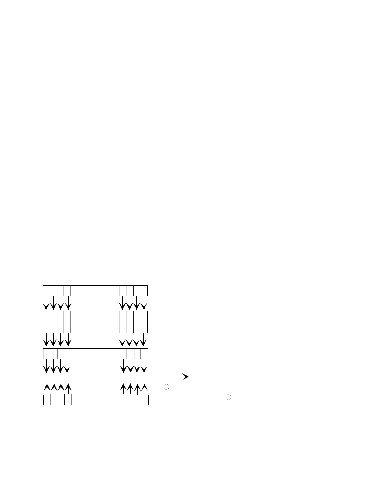
Instrument Model and Command Processing
The instrument model shown in Fig. 5-2 has been m ade viewed from the standpoint of the servicing of
IEC-bus commands . The individual components work independently of each other and sim ultaneously.
They communicate by means of so-called "messages".
Input unit with
IEC Bus
input puffer
Command
recognition
Data set
Status reporting-
system
Instrument
hardware
Output unit with
IEC Bus
Fig. 5-2 Instrument model in the case of remote control by means of the IEC bus
output buf f er
Input Unit
The input unit receives com mands character by character from the IEC bus and collects them in the
input buffer. The input unit sends a message to the com mand recognition as soon as the input buffer is
full or as soon as it rece ives a delimiter, <PROGRAM MESSAGE T ERMINATOR>, as defined in IEEE
488.2, or the interface message DCL.
If the input buffer is full, the IEC-bus traf fic is stopped and the data rec eived up to then are processed.
Subsequently the IEC-bus traffic is continued. If, however, the buf fer is not yet full when receiving the
delimiter, the input unit can already receive the next command during command recognition and
execution. The receipt of a DCL clears the input buffer and immediately initiates a message to the
command recognition.
1093.4820.12 5.15 E-2

Status Reporting System FSP
Command Recognition
The comm and recognition analyses the data received from the input unit. It proceeds in the order in
which it receives the data. Only a DCL is serviced with priority, a GET (Group Execute T rigger), e.g., is
only executed after the comm ands received before as well. Eac h recognized comm and is im mediately
transferred to the instrument data base but without being executed there at once.
Syntactical errors in the command are recognized in the command recognition and supplied to the
status reporting system. The res t of a comm and line after a syntax error is analysed further if poss ible
and serviced.
If the command recognition recognizes a delimiter (<PROGRAM MESSAGE SEPARATOR> or
<PROGRAM MESSAGE TERMINATOR>) or a DCL, it requests the instrument data bas e to set the
commands in the ins trum ent hardware as well now. Subsequently it is imm ediately prepared to process
commands again. This means for the command servicing that further commands can already be
serviced while the hardware is still being set ("overlapping execution").
Instrument Data Base and Instrument Hardware
Here the expression "instrument hardware" denotes the part of the instrument fulfilling the actual
instrument function - signal generation, measurement etc. The controller is not included.
The instrument data base is a detailed reproduction of the instrument hardware in the software.
IEC-bus setting comm ands lead to an alteration in the data set. The data base managem ent enters the
new values (e.g. frequency) into the data base, however, only passes them on to the hardware when
requested by the command recognition.
The data are only checked for their c ompatibility among each other and with the instrum ent hardware
immediately before they are transmitted to the instrument hardware. If the detection is made that an
execution is not possible, an "execution error" is signalled to the status reporting system. The alter ation
of the data base are cancelled, the instrument hardware is not reset.
IEC-bus queries induce the data base management to send the desired data to the output unit.
Status Reporting System
The status reporting system c ollects information on the instrum ent state and makes it available to the
output unit on request. The exact structure and function are described in Section 3.8
1093.4820.12 5.16 E-2

FSP Status Reporting System
Output Unit
The output unit collects the information requested by the controller, which it receives f rom the data bas e
management. It processes it according to the SCPI rules and makes it available in the output buffer.
If the instrument is address ed as a talk er without the output buff er containing data or awaiting data from
the data base management, the output unit sends error message "Query UNTERMINATED" to the
status reporting system. No data are sent on the IEC bus, the controller waits until it has reac hed its
time limit. This behaviour is specified by SCPI.
Command Sequence and Command Synchronization
What has been said above makes clear that all commands can potentially be carried out overlapping.
In order to prevent an overlapping execution of comm ands, one of commands *OPC, *OPC? or *WAI
must be used. All three commands cause a cer tain action only to be carried out after the hardware has
been set and has settled. By a suitable programming, the controller can be forced to wait for the
respective action to occur (cf. Table 5-1).
Table 5-1 Synchronisation using *OPC, *OPC? and *WAI
Command Action after the hardware has settled Programming the controller
*OPC Setting the opteration-complete bit in the ESR - Setting bit 0 in the ESE
*OPC? Writing a " 1" i nto the output buffer Addressing the instrument as a talker
*WAI Continuing the I E C-bus handshake Sending the next command
- Setting bit 5 in the SRE
- Waiting for service request (SRQ)
An example as to command synchronization can be found in Chapter "Program Examples".
For a couple of comm ands the s ynchronization to the end of comm and execution is m andatory in order
to obtain the desired result. The affected commands require either more than one measurement in
order to accomplish the desired instrument setting (eg autorange functions), or they require a longer
period of time for execution. If a new command is received during execution of the corresponding
function this may either lead to either to an aborted measurement or to invalid measurement data.
The following list includes the commands, for which a synchronization via *OPC, *OPC? or *WAI is
mandatory:
Table 5-1 Commands with mandatory synchronization (Overlapping Commands)
Command Purpose
INIT start measurem ent
INIT:CONM continue measurement
CALC:MARK:FUNC:ZOOM zoom frequency range around marker 1
CALC:STAT:SCAL:AUTO ONCE optimi ze level settings for signal st atistic measurement
[SENS:]POW:ACH:PRES: RLE V optimize level sett i ngs for adjacent channel power
functions
measurements
1093.4820.12 5.17 E-2
Status Reporting System FSP
D
Status Reporting System
The status reporting system ( cf. Fig. 5-4) stores all information on the present operating state of the
instrument, e.g. that the instrument presently carries out a calibration and on errors which have
occurred. This inf ormation is stored in the status registers and in the error queue. T he status registers
and the error queue can be queried via IEC bus.
The information is of a hierarchic al structure. T he register status byte (STB) defined in IEEE 488.2 and
its associated mask regist er service r equest enable (SRE) for m the upper mos t level. The STB receives
its information f rom the standard event status register ( ESR) which is also defined in IEEE 488.2 with
the associated mask register standar d event status enable ( ESE) and r egis ters STATus:OPERation and
STATus:QUEStionable which are defined by SCPI and contain detailed information on the instrument.
The IST flag ("Individual ST atus") and the parallel poll enable regis ter (PPE) alloc ated to it are also part
of the status reporting system. T he IST flag, like the SRQ, com bines the entire instrument status in a
single bit. The PPE fulfills the same function for the IST flag as the SRE for the service request.
The output buffer contains the messages the instrum ent returns to the controller. It is not part of the
status reporting system but determines the value of the MAV bit in the STB and thus is represented in
Fig. 5-4.
Structure of an SCPI Status Register
Each SCPI register consists of 5 parts which each have a width of 16 bits and have different func tions
(cf. Fig. 5-3). The individual bits are independent of each other, i.e. each hardware status is assigned a
bit number which is valid for all five parts. For example, bit 3 of the STATus:OPERation register is
assigned to the hardware status "wait for trigger" in all f ive parts . Bit 15 ( the most significant bit) is s et to
zero for all parts. Thus the contents of the register parts can be processed by the controller as pos itive
integer.
15 14 13 12 CONDition part 3 2 1 0
15 14 13 12 PTRansition part 3 2 1 0
15 14 13 12 NTRansition part 3 2 1 0
15 14 13 12 EVENt part 3 2 1 0
to high er -or der reg ister
& & & & & & & & & & & & & & & &
15 14 13 12 ENABle part 3 2 1 0
Sum b it
+
& = logical AN
= logic al OR
+
of all bits
Fig. 5-3 The status-register model
1093.4820.12 5.18 E-2

FSP Status Reporting System
CONDition part The CONDition part is directly written into by the hardware or the sum bit of
the next lower register. Its contents reflects the current ins trum ent status . T his
register part can only be read, but not written into or cleared. Its contents is
not affected by reading.
PTRansition part The Positive-TRansition part acts as an edge detector. When a bit of the
CONDition part is changed from 0 to 1, the associated PTR bit decides
whether the EVENt bit is set to 1.
PTR bit =1: the EVENt bit is set.
PTR bit =0: the EVENt bit is not set.
This part can be written into and read at will. Its contents is not af fected by
reading.
NTRansition part The Negative-TRansition part also acts as an edge detector . When a bit of the
CONDition part is changed from 1 to 0, the associated NTR bit decides
whether the EVENt bit is set to 1.
NTR-Bit = 1: the EVENt bit is set.
NTR-Bit = 0: the EVENt bit is not set.
This part can be written into and read at will. Its contents is not af fected by
reading.
With these two edge register parts the user can define which state transition of
the condition part (none, 0 to 1, 1 to 0 or both) is stored in the EVENt part.
EVENt part The EVENt part indicates whether an event has occurred since the last
reading, it is the "memory" of the condition part. It only indicates events
passed on by the edge filters. It is permanently updated by the instrument.
This part can only be read by the user. During reading, its contents is set to
zero. In linguistic usage this part is often equated with the entire register.
ENABle part The ENABle part determines whether the associated EVENt bit contr ibutes to
the sum bit (cf. below). Each bit of the EVENt part is ANDed with the
associated ENABle bit (symbol '&'). The r esults of all logic al operations of this
part are passed on to the sum bit via an OR function (symbol '+').
ENABle-Bit = 0: the associated EVENt bit does not contribute to the sum bit
ENABle-Bit = 1: if the associated EVENT bit is "1", the sum bit is set to "1" as
well.
This part can be written into and read by the user at will. Its contents is not
affected by reading.
Sum bit As indicated above, the sum bit is obtained f rom the EVENt and ENABle part
for each register. The r esult is then entered into a bit of the CONDition part of
the higher-order register.
The instrument autom atic ally generates the sum bit f or each register . T hus an
event, e.g. a PLL that has not locked, can lead to a service request throughout
all levels of the hierarchy.
Note: The service request enable regis ter SRE defined in IEEE 488.2 can be taken as ENABle
part of the STB if the STB is structured according to SCPI. By analogy, the ESE can be
taken as the ENABle part of the ESR.
1093.4820.12 5.19 E-2

Status Reporting System FSP
Overview of the Status Registers
not used
&=logic AND
=logic OR
of all bits
SRQ
15
14
13
12
11
10
Scan results available
9
HCOPy in progress
8
7
6
5
4
3
2
1
CALibrating
0
STATus:OPERation
not used
15
14
ALT2 LOWer FAIL (screen B)
13
ALT2 UPPer FAIL (screen B)
12
ALT1 LOWer FAIL (screen B)
11
ALT1 UPPer FAIL (screen B)
10
ADJ LOWer FAIL (screen B)
9
ADJ UPPer FAIL (screen B)
8
7
6
5
ALT2 LOWer FAIL (screen A)
4
ALT2 UPPer FAIL (screen A)
3
ALT1 LOWer FAIL (screen A)
2
ALT1 UPPer FAIL (screen A)
1
ADJ LOWer FAIL (screen A)
0
ADJ UPPer FAIL (screen A)
STATus:QUEStionable:ACPLimit
not used
15
14
13
12
11
10
9
8
7
6
5
4
3
CARRier overload (screen A)
2
No carrier (screen A)
1
SYNC not found (screen A)
0
BURSt not found (screen A)
STATus:QUEStionable:SYNC
-&-
-&-
-&-
-&-
-&-
SRE
-&-
-&-
-&-
-&-
-&-
-&-
PPE
ISTflag
7
RQS/MSS
6
5
ESB
4
MAV
3
2
1
0
ST B
Error/event
queue
bla
15
14
13
12
11
10
STATus:QUEStionable
-&-
-&-
-&-
-&-
-&-
-&-
-&-
Output
buffer
-&-
ESE ESR
not used
TRANsducer break
ACPLimit
SYNC
LMARgin
9
LIMit
8
CALibration (= UNCAL)
7
6
5
FREQuency
4
TEMPerature
POW e r
3
2
1
0
Power on
7
User Request
6
CommandError
5
Execution Error
4
Device Dependent Error
3
Query Error
2
Request Control
1
0
Operation Complete
Screen A
not used not used
15
14
13
12
11
10
9
8
LMARgin 8 FAIL
7
LMARgin 7 FAIL
6
LMARgin 6 FAIL
5
LMARgin 5 FAIL
4
LMARgin 4 FAIL
3
LMARgin 3 FAIL
2
LMARgin 2 FAIL
1
LMARgin 1 FAIL
0
STATus:QUEStionable:LMARgin <1|2>
not used not used
15
14
13
12
11
10
LO UNLocked (screen B)
9
8
7
6
5
4
3
2
LO UNLocked (screen A)b
1
OVEN COLD
0
STATus:QUEStionabl e:FREQuency
Screen B
15
14
13
12
11
10
9
8
7
6
5
4
3
2
1
0
15
14
13
12
11
10
9
8
7
6
5
4
3
2
1
0
Screen A Screen B
15
14
13
12
11
10
9
8
LIMit 8 FAIL
7
LIMit 7 FAIL
6
LIMit 6 FAIL
5
LIMit 5 FAIL
4
LIMit 4 FAIL
3
LIMit 3 FAIL
2
LIMit 2 FAIL
1
LIMit 1 FAIL
0
STATus:QUEStionable:LIMit<1|2>
IF_OVerload (s creen B)
UNDerload
OVERload (screen B)
IF_OVerload (s creen A)
UNDerload
OVERload (screen A)
STATus:QUEStionable:POWer
(screen B )
(screen A)
15
14
13
12
11
10
9
8
7
6
5
4
3
2
1
0
Fig. 5-4 Overview of the status registers
1093.4820.12 5.20 E-2

FSP Status Reporting System
Description of the Status Registers
Status Byte (STB) and Service Request Enable Register (SRE)
The STB is already defined in IEEE 488.2. It provides a rough overview of the instrument status by
collecting the pieces of inform ation of the lower registers. It can thus be com pared with the CONDition
part of an SCPI register and assum es the highest level within the SCPI hierarchy. A special f eature is
that bit 6 acts as the sum bit of the remaining bits of the status byte.
The STATUS BYTE is read out using the command "*STB?" or a serial poll.
The STB implies the SRE. It corresponds to the ENABle part of the SCPI registers as to its function.
Each bit of the STB is assigned a bit in the SRE. Bit 6 of the SRE is ignored. If a bit is set in the SRE
and the associated bit in the STB changes f rom 0 to 1, a Service Request (SRQ) is generated on the
IEC bus, which triggers an interrupt in the controller if this is appropriately configured and c an be f urther
processed there.
The SRE can be set using command "*SRE" and read using "*SRE?".
Table 5-2 Meaning of the bits in the status byte
Bit No. Meaning
2
3
4
5
6
Error Queue not empty
The bit is set when an entry is m ade i n the error queue.
If this bit is enabl ed by the SRE, each entry of the error queue generates a Service Request. Thus an error can
be recognized and specified in greater detail by polling the error queue. The poll provides an informative error
message. This proc edure i s to be recommended since it considerably reduces t he probl ems involved with IECbus control.
QUEStionable status sum bit
The bit is set if an EV E Nt bit is set in the QUES t i onabl e: status register and the as sociated ENABle bit is set
to 1.
A set bit indicates a questionable instrument status, which can be specified in greater detail by polling the
QUEStionable status regi ster.
MAV bit (message available)
The bit is set if a message is available in the output buffer which can be read.
This bit can be used to enable data to be automatically read from the instrument to the controller (cf. Chapter 7,
program examples).
ESB bit
Sum bit of the event s tatus register. It i s set if one of the bits i n the event status register i s set and enabled in
the event status enable regis ter.
Setting of this bit i mplies an error or an event which can be speci fied in greater detail by polling the event status
register.
MSS bit (master status summary bit )
The bit is set if the i nstrument triggers a service request. This is the case if one of the other bits of this registers
is set together with its mask bit in the servi ce request enable register SRE.
7
OPERation status register sum bit
The bit is set if an EV E Nt bit is set in the OPE Rat i on-S tatus register and the associated ENABle bit is s et to 1.
A set bit indicates that the instrument i s just performing an act i on. The type of action can be determined by
polling the OPERation-stat us register.
1093.4820.12 5.21 E-2

Status Reporting System FSP
IST Flag and Parallel Poll Enable Register (PPE)
By analogy with the SRQ, the IST flag combines the entire status information in a single bit. It can be
queried by means of a parallel poll (cf. Section 3.8.4.3) or using command "*IST?".
The parallel poll enable register (PPE) deter mines which bits of the STB contribute to the IST f lag. The
bits of the STB are ANDed with the corresponding bits of the PPE, with bit 6 being used as well in
contrast to the SRE. The Ist flag results from the ORing of all results. The PPE can be set using
commands "*PRE" and read using command "*PRE?".
Event-Status Register (ESR) and Event-Status-Enable Register (ESE)
The ESR is already defined in IEEE 488.2. It can be compared with the EVENt part of an SCPI r egister.
The event status register can be read out using command "*ESR?".
The ESE is the associated ENABle part. It can be s et us ing c ommand "*ESE" and read using command
"*ESE?".
Table 5-3 Meaning of the bits in the event status register
Bit No. Meaning
0
1 This bit is not used
2
3
4
5
6
Operation Complete
This bit is set on recei pt of the command *OP C exactl y when all previous commands have been executed.
Query Error
This bit is set if ei ther the controller wants to read data from the instrument without havi ng send a query, or if it
does not fetch requested data and sends new instructions to the i nstrument instead. The cause is often a query
which is faulty and hence cannot be executed.
Device-dependent Error
This bit is set if a devi ce-dependent error occurs. An error m essage with a number between -300 and -399 or a
positive error number, which denotes t he error i n greater detail, is entered into t he error queue (cf. Chapter 9,
Error Messages).
Execution Error
This bit is set if a received command is s ynt actically correct, however, c annot be performed for other reasons.
An error message with a number bet ween -200 and -300, which denotes the error in greater detail, is ent ered
into the error queue (cf. Chapter 9, E rror Mes sages).
Command Error
This bit is set if a command which is undefined or s ynt actically incorrect is received. An error message with a
number between -100 and -200, which denotes the error in greater detail, is entered into the error queue (cf .
Chapter 9 "Error Messages").
User Request
This bit is set on pressing the LOCAL key.
7
Power On (supply voltage on)
This bit is set on switching on the instrument.
1093.4820.12 5.22 E-2

FSP Status Reporting System
STATus:OPERation Register
In the CONDition part, this register contains information on which actions the instrument is being
executing or, in the EVENt part, inform ation on which ac tions the ins tr ument has executed s ince the las t
reading. It can be read using commands "STATus:OPERation:CONDition?" or "STATus
:OPERation[:EVENt]?".
Table 5-4 Meaning of the bits in the STATus.OPERation register
Bit No. Meaning
0
1 to 7 These bits are not used
8
9 to 14 These bit s are not used
15 This bit is always 0
CALibrating
This bit is set as l ong as the instrument is performing a calibration.
HardCOPy in progress
This bit is set while the instrument is printing a hardcopy.
1093.4820.12 5.23 E-2

Status Reporting System FSP
STATus:QUEStionable Register
This register comprises information about indefinite states which may occur if the unit is operated
without meeting the specifications. It can be queried by commands STATus:QUEStionable:
CONDition? and STATus:QUEStionable[:EVENt]?.
Table 5-5 Meaning of bits in STATus:QUEStionable register
Bit No. Meaning
0 to 2 These bits are not used
3
4
5
6 to 7 These bits are not used
8
9
10
11
12
POWer
This bit is set if a questionable power occurs (cf. als o section "STATus:QUES tionable:POWer Register")
TEMPerature
This bit is set if a questionable temperature occurs.
FREQuency
The bit is set if a frequenc y i s questionable (cf. sec tion "STATus:QUEStionabl e:FREQuency Register")
CALibration
The bit is set if a measurement is performed uncalibrated (=^ label "UNCAL")
LIMit (device-specific )
This bit is set if a limit value is violat ed (see also section STAT us:QUEStionable:LIMit Regi ster)
LMARgin (device-specific)
This bit is set if a margin is violated (see als o section STATus:QUE Stionable:LMARgin Register)
SYNC (device-dependent)
This bit is set if , in measurements or premeasurements in GSM MS mode, synchronization to mi damble fails or
no burst is found.
This bit is also set i f, in premeasurements in GSM MS mode, the result differs too strongly from the expected
value (see also "STATus:QUE Stionable:SYNC Register").
ACPLimit (device-specific)
This bit is set if a l i mit for the adjacent c hannel power m easurement is violated (see al so section
"STATus:QUEStionable: A CP Li mit Register")
13 to 14 These bits are not used
15 This bit is always 0.
1093.4820.12 5.24 E-2

FSP Status Reporting System
STATus QUEStionable:ACPLimit Register
This register comprises information about the observance of limits during adjacent power
measurements. It can be queried with commands 'STATus:QUEStionable:ACPLimit
:CONDition?' and 'STATus:QUEStionable:ACPLimit[:EVENt]?'
Table 5-6 Meaning of bits in STATus:QUEStionable:ACPLimit register
Bit No. Meaning
0
1
2
3
4
5
6 to 7 not used
8
9
ADJ UPPer FAIL(Screen A)
This bit is set if i n screen A. the limit i s exceeded in the upper adjacent channel
ADJ LOWer FAIL (Screen A)
This bit is set if i n screen A the limit is exceeded in the lower adjacent channel.
ALT1 UPPer FAIL (Screen A)
This bit is set if i n screen A the limit is exceeded in the upper 1st alternate channel.
ALT1 LOWer FAIL (Screen A)
This bit is set if i n screen A the limit is exceeded in the lower 1st alternate channel.
ALT2 UPPer FAIL (Screen A)
This bit is set if i n screen A the limit is exceeded in the upper 2nd alternate channel.
ALT2 LOWer FAIL (Screen A)
This bit is set if i n screen A the limit is exceeded in the lower 2nd alternate channel.
ADJ UPPer FAIL (Screen B)
This bit is set if i n screen B the limit is exceeded in the upper adjacent channel.
ADJ LOWer FAIL (Screen B)
This bit is set if in screen
B the limit is exceeded in the lower adjacent channel.
10
11
12
13
14 not used
15 This bit is always set to 0.
ALT1 UPPer FAIL (Screen B)
This bit is set if i n screen B the limit is exceeded in the upper 1st alternate channel.
ALT1 LOWer FAIL (Screen B)
This bit is set if
ALT2 UPPer FAIL (Screen B)
This bit is set if i n screen B the limit is exceeded in the upper 2nd alternate channel.
ALT2 LOWer FAIL (Screen B)
This bit is set if i n screen B the limit is exceeded in the lower 2nd alternate channel.
in screen B the limi t i s exceeded in the lower 1st alternate channel.
1093.4820.12 5.25 E-2

Status Reporting System FSP
STATus QUEStionable:FREQuency Register
This register comprises information aboutthe reference and local oscillator.
It can be queried with commands STATus:QUEStionable:FREQuency:CONDition? and "STATus
:QUEStionable:FREQuency[:EVENt]?.
Table 5-7 Meaning of bits in STATus:QUEStionable:FREQuency register
Bit No. Meaning
0
1
2 to 8 not used
9
10 to 14 not used
15 This bit is always 0.
OVEN COLD
This bit is set if the reference os cillator has not yet attained its operating temperature. 'OCXO' will then be
displayed.
LO UNLocked (Screen A)
This bit is set if the local oscillat or no longer locks. 'LOUNL will then be displayed.
LO UNLocked (Screen B)
This bit is set if the local oscillat or no longer locks.' LOUNL' will then be displayed.
1093.4820.12 5.26 E-2

FSP Status Reporting System
STATus QUEStionable:LIMit<1|2> Register
This register comprises information about the observance of limit lines in the corresponding
measurement window (LIMit 1 corr esponds to Screen A, LIMit 2 to Screen B). It can be queried with
commands STATus:QUEStionable:LIMit<1|2>:CONDition? and STATus:QUEStionable:
LIMit<1|2>[:EVENt]?.
Table 5-8 Meaning of bits in STATus:QUEStionable:LIMit<1|2> register
Bit No. Meaning
0
1
2
3
4
5
6
7
LIMit 1 FAIL
This bit is set if limit line 1 is violated.
LIMit 2 FAIL
This bit is set if limit line 2 is violated.
LIMit 3 FAIL
This bit is set if limit line 3 is violated.
LIMit 4 FAIL
This bit is set if limit line 4 is violated.
LIMit 5 FAIL
This bit is set if limit line 5 is violated.
LIMit 6 FAIL
This bit is set if limit line 6 is violated.
LIMit 7 FAIL
This bit is set if limit line 7 is violated.
LIMit 8 FAIL
This bit is set if limit line 8 is violated.
8 to 14 not used
15 This bit is always 0.
1093.4820.12 5.27 E-2

Status Reporting System FSP
STATus QUEStionable:LMARgin<1|2> Register
This register comprises information about the observance of limit margins in the corresponding
measurement window (LMARgin1 corresponds to Screen A, LMARgin2 corresponds to Screen B). It
can be queried with commands STATus:QUEStionable:LMARgin<1|2>:CONDition? and
"STATus :QUEStionable:LMARgin<1|2>[:EVENt]?.
Table 5-9 Meaning of bits in STATus:QUEStionable:LMARgin<1|2> register
Bit No. Meaning
0
1
2
3
4
5
6
7
LMARgin 1 FAIL
This bit is set if limit margin 1 is violated.
LMARgin 2 FAIL
This bit is set if limit margin 2 is violated.
LMARgin 3 FAIL
This bit is set if limit margin 3 is violated.
LMARgin 4 FAIL
This bit is set if limit margin 4 is violated.
LMARgin 5 FAIL
This bit is set if limit margin 5 is violated.
LMARgin 6 FAIL
This bit is set if limit margin 1 is violated.
LMARgin 7 FAIL
This bit is set if limit margin 7 is violated.
LMARgin 8 FAIL
This bit is set if limit margin 8 is violated.
8 to 14 not used
15 This bit is always 0.
1093.4820.12 5.28 E-2

FSP Status Reporting System
STATus QUEStionable:POWer Register
This register comprises all information about possible overloads of the unit.
It can be queried with commands STATus:QUEStionable:POWer:CONDition? and "STATus
:QUEStionable:POWer[:EVENt]?.
Table 5-10 Meaning of bits in STATus:QUEStionable:POWer register
Bit No. Meaning
0
1
2
3 to 7 not used
8
9
10
11 to 14 not used
15 This bit is always 0.
OVERload (Screen A)
This bit is set if the RF input is overloaded. 'OVLD' will then be displayed.
UNDerload (Screen A)
This bit is set if the RF input is underloaded. 'UNLD' will then be displayed.
IF_OVerload (Screen A)
This bit is set if the IF path is overloaded. 'IFOVL' will then be displayed.
OVERload (Screen B)
This bit is set if the RF input is overloaded. 'OVLD' will then be displayed.
UNDerload (Screen B)
This bit is set if the RF input is underloaded. 'UNLD' will then be displayed.
IF_OVerload (Screen B)
This bit is set if the IF path is overloaded. 'IFOVL' will then be displayed.
1093.4820.12 5.29 E-2

Status Reporting System FSP
STATus-QUEStionable:SYNC Register
This register is used only with GSM MS mode. It contains inform ation about sync and bursts not found,
and about premeasurement results exceeding or falling short of expected values.
The bits can be queried with commands "STATus:QUEStionable:SYNC:CONDition?" and
"STATus:QUEStionable:SYNC[:EVENt]?".
Table 5-11 Meaning of bits in STATus:QUEstionable:SYNC register
Bit No. Meaning
0
1
2
3
4-14 Not used.
BURSt not found (screen A)
This bit is set if no burst is found in the meas urements/premeasurements for
phase/frequency error (PFE) or carrier power versus t i me (PVT) in GSM MS mode.
If a burst is found in t hese measurements/ premeasurements, t he bi t i s reset.
SYNC not found (screen A)
This bit is set if the synchronization sequence (training sequence) of the midambl e i s not found in the
measurements/ premeasurements for phase/frequency error (PFE) or carrier power versus ti me (PVT)
in GSM MS mode.
If the synchronization sequence (training sequence) of the m i damble is found in these
measurements/ premeasurements, t he bi t is reset.
No carrier (screen A)
This bit is set if , in GSM MS mode, the level value determined in the premeasurement s for
carrier power versus time (PVT ) and spectrum due to modulation is too low.
The bit is reset at the beginning of the premeasurement
(see also Chapter 2, descript i on of the named premeasurem ents).
Carrier overload (screen A)
This bit is set if , in GSM MS mode, the level value determined in the premeasurement s for
carrier versus time (P VT) and spectrum due to modulation is too high.
The bit is reset at the beginning of the premeasurement
(see also Chapter 2, descript i on of the named premeasurem ents).
15 This bit is always 0.
1093.4820.12 5.30 E-2

FSP Status Reporting System
Application of the Status Reporting Systems
In order to be able to effectively use the status reporting s ystem, the information contained there mus t
be transmitted to the controller and further processed there. There are several methods which are
represented in the following. Detailed program examples are to be found in chapter 7, Program
Examples.
Service Request, Making Use of the Hierarchy Structure
Under certain circums tanc es , the instr ument can send a service request ( SRQ) to the contr oller. Us ually
this service request initiates an interrupt at the c ontroller, to which the control program can react with
corresponding actions. As evident from Fig. 5-4, an SRQ is always initiated if one or sever al of bits 2, 3,
4, 5 or 7 of the status byte are set and enabled in the SRE. Each of these bits combines the inform ation
of a further register, the error queue or the output buffer. The cor responding s etting of the ENABle parts
of the status registers c an achieve that arbitrary bits in an arbitrary status register initiate an SRQ. In
order to make use of the possibilities of the service request, all bits should be set to "1" in enable
registers SRE and ESE.
Examples (cf. Fig. 5-4 and chapter 7, Program Examples, as well):
Use of command "*OPC" to generate an SRQ at the end of a sweep.
Ø CALL IBWRT(analyzer%, "*ESE 1")Set bit 0 in the ESE (Operation Complete)
Ø CALL IBWRT(analyzer%, "*SRE 32")Set bit 5 in the SRE (ESB)?
After its settings have been completed, the instrument generates an SRQ.
The SRQ is the only possibility for the instrument to bec ome active on its own. Eac h controller program
should set the instrument in a way that a service request is initiated in the case of malfunction. The
program should react appropriately to the service request. A detailed example for a service request
routine is to be found in chapter 7, Program Examples.
Serial Poll
In a serial poll, just as with comm and "*STB", the status byte of an instrument is queried. However, the
query is realized via interface messages and is thus c learly faster. The serial-poll method has already
been defined in IEEE 488.1 and used to be the only standard possibility for different instr uments to poll
the status byte. The method also works with instruments which do not adhere to SCPI or IEEE 488.2.
The VISUAL BASIC command for executing a serial poll is "IBRSP()". Serial poll is mainly used to
obtain a fast overview of the state of several instruments connected to the IEC bus.
1093.4820.12 5.31 E-2

Status Reporting System FSP
Parallel Poll
In a parallel poll, up to eight instruments are s imultaneously requested by the controller by means of a
single command to transmit 1 bit of inf orm ation eac h on the data lines, i.e., to set the data line alloc ated
to each instrument to logically "0" or "1". By analogy to the SRE register which determ ines under which
conditions an SRQ is generated, there is a parallel poll enable register (PPE) whic h is ANDed with the
STB bit by bit as well considering bit 6. The results are ORed, the res ult is then sent ( possibly inverted)
as a response in the parallel poll of the controller. The result can also be queried without parallel poll by
means of command "*IST".
The instrument first has to be set for the parallel poll using quick-BASIC command "IBPPC()". This
command allocates a data line to the ins tr ument and determines whether the response is to be inver ted.
The parallel poll itself is executed using "IBRPP()".
The parallel-poll method is mainly used in order to quickly find out after an SRQ which instrum ent has
sent the service request if there are many instrum ents connected to the IEC bus. To this effect, SRE
and PPE must be set to the same value. A detailed example as to the parallel poll is to be found in
chapter 7, Program Examples.
Query by Means of Commands
Each part of every status register can be read by means of queries. The individual commands are
indicated in the detailed description of the registers in Section 3.8.3. What is returned is always a
number which represents the bit pattern of the regis ter queried. Evaluating this number is effected by
the controller program.
Queries are usually used after an SRQ in order to obtain more detailed inform ation on the cause of the
SRQ.
Error-Queue Query
Each error state in the instrum ent leads to an entry in the error queue. The entries of the error queue
are detailed plain-text error messages which can be looked at in the ERROR m enu via manual control
or queried via the IEC bus using command "SYSTem:ERRor?". Each call of "SYSTem:ERRor?"
provides an entry from the error queue. If no error m essages are stored ther e any more, the instrum ent
responds with 0, "No error".
The error queue should be queried after every SRQ in the controller program as the entr ies des c ribe the
cause of an error mor e precisely than the status registers. Especially in the test phase of a controller
program the error queue should be quer ied regularly since faulty commands from the c ontroller to the
instrument are recorded there as well.
1093.4820.12 5.32 E-2

FSP Status Reporting System
Resetting Values of the Status Reporting System
Table 5-12 comprises the diff erent commands and events causing the status reporting system to be
reset. None of the commands, except for *RST and SYSTem:PRESet influences the functional
instrument settings. In particular, DCL does not change the instrument settings.
Table 5-12 Resettting instrument functions
Event Switching on supply
Effect 0 1
Clear STB,ESR
Clear SRE,ESE
Clear PPE
Clear EVENTt parts of t he
registers
Clear Enable parts of all
OPERation and
QUEStionable registers,
Fill Enable parts of all
other registers with "1".
Fill PTRansition parts with
"1" ,
Clear NTRansition parts
Clear error queue yes yes
voltage DCL,SDC
Power-On-Status-
Clear
yes
yes
yes
yes
yes
yes
(Device Clear,
Selected Device
Clear)
*RST or
SYSTem:PRESet
STATus:PRESet *CLS
yes
yes
yes
yes
yes
Clear output buffer yes yes yes 1) 1) 1)
Clear command
processing and input
buffer
1) Every command being the first in a com mand line, i.e., immediately following a <PROGRAM MESSAGE TERMINATOR>
clears the output buffer.
yes yes yes
1093.4820.12 5.33 E-2


FSP Contents - Description of Commands
Contents - Chapter 6
"Remote Control - Description of Commands"
6 Remote Control - Description of Commands....................................................6.1
Notation ............................................................................................................................................6.1
Common Commands....................................................................................................................... 6.4
ABORt Subsystem...........................................................................................................................6.8
CALCulate Subsystem.....................................................................................................................6.8
CALCulate:DELTamarker Subsystem..................................................................................... 6.9
CALCulate:FEED Subsystem................................................................................................ 6.17
CALCulate:LIMit Subsystem..................................................................................................6.19
CALCulate:LIMit:SPECtrum Subsystem ..................................................................... 6.24
CALCulate:LIMit:ACPower Subsystem .......................................................................6.26
CALCulate:LIMit:CONTrol Subsystem ........................................................................6.37
CALCulate:LIMit:LOWer Subsystem........................................................................... 6.39
CALCulate:LIMit:UPPer Subsystem............................................................................ 6.42
CALCulate:MARKer Subsystem............................................................................................ 6.45
CALCulate:MARKer:FUNCtion:ADEMod Subsystem .................................................6.53
CALCulate:MARKer:FUNCtion Subsystem................................................................. 6.55
CALCulate:MARKer:FUNCtion:POWer Subsystem....................................................6.65
CALCulate:MARKer:FUNCtion:STRack Subsystem...................................................6.70
CALCulate:MARKer:FUNCtion:SUMMary Subsystem................................................6.72
CALCulate:MARKer:FUNCtion-Subsystem - WCDMA 3GP FDD BTS and MS
(FS-K72/K73) ..............................................................................................................6.84
CALCulate:MATH Subsystem ...............................................................................................6.87
CALCulate:STATistics Subsystem ........................................................................................6.89
CALCulate:THReshold Subsystem ....................................................................................... 6.93
CALCulate:UNIT Subsystem................................................................................................. 6.95
CALibration Subsystem................................................................................................................ 6.96
CONFigure – Subsystem...............................................................................................................6.98
CONFigure:BURSt - Subsystem .........................................................................................6.102
CONFigure:SPECtrum - Subsystem ................................................................................... 6.105
CONFigure:SPURious - Subsystem.................................................................................... 6.106
CONFigure:WCDPower - Subsystem .................................................................................6.107
DIAGnostic Subsystem............................................................................................................... 6.114
DISPlay Subsystem......................................................................................................................6.117
FETCh - Subsystem..................................................................................................................... 6.125
FETCh:BURSt - Subsystem ................................................................................................6.125
FETCh:PTEMplate Subsystem............................................................................................6.139
1093.4820.12 I-6.1 E-3

Contents - Description of Commands FSP
FETCh:SPECtrum Subsystem ............................................................................................ 6.140
FORMat Subsystem..................................................................................................................... 6.143
HCOPy Subsystem ......................................................................................................................6.144
INITiate Subsystem...................................................................................................................... 6.150
INPut Subsystem .........................................................................................................................6.152
INSTrument Subsystem ..............................................................................................................6.155
MMEMory Subsystem.................................................................................................................. 6.157
OUTPut Subsystem .....................................................................................................................6.170
READ - Subsytem.........................................................................................................................6.171
READ:AUTO - Subsystem...................................................................................................6.171
READ:BURSt - Subsystem..................................................................................................6.173
READ:SPECtrum Subsystem.............................................................................................. 6.187
SENSe Subsystem.......................................................................................................................6.190
[SENSe:]ADEMod - Subsystem........................................................................................... 6.190
SENSe:AVERage Subsystem .............................................................................................6.204
SENSe:BANDwidth Subsystem...........................................................................................6.206
SENSe:CDPower Subsystem..............................................................................................6.211
SENSe:CORRection Subsystem......................................................................................... 6.216
SENSe:DETector Subsystem.............................................................................................. 6.220
SENSe:FREQuency Subsystem..........................................................................................6.221
SENSe:LIST Subsystem...................................................................................................... 6.224
SENSe:MPOWer Subsystem.............................................................................................. 6.230
SENSe:POWer Subsystem................................................................................................. 6.234
SENSe:ROSCillator Subsystem.......................................................................................... 6.240
SENSe:SWEep Subsystem................................................................................................. 6.241
SENSe:TV Subsystem......................................................................................................... 6.245
SOURce Subsystem ....................................................................................................................6.246
Internal Tracking Generator.................................................................................................6.246
SOURce:EXTernal Subsystem...........................................................................................6.249
STATus Subsystem..................................................................................................................... 6.253
SYSTem Subsystem .................................................................................................................... 6.263
TRACe Subsystem....................................................................................................................... 6.274
General Trace Commands..................................................................................................6.274
Number and format of the measurement values for the different operating modes .6.276
TRACe:IQ Subsystem .........................................................................................................6.281
TRIGger Subsystem..................................................................................................................... 6.291
1093.4820.12 I-6.2 E-3

FSP Contents - Description of Commands
UNIT Subsystem ..........................................................................................................................6.297
Supported GPIB Commands of the HP 8590 Series.................................................................6-298
Supported Command Subset ..............................................................................................6-298
Differences in Status Reporting...........................................................................................6-304
Differences in GPIB behavior between the FSP and the FSE families of instruments......... 6.305
Alphabetical List of Commands................................................................................................. 6.329
Table of Softkeys with IEC/IEEE-Bus Command Assignment ............................................................ 6.344
FREQUENCY Key............................................................................................................... 6.344
SPAN Key............................................................................................................................6.345
AMPT Key............................................................................................................................ 6.346
MKR Key..............................................................................................................................6.347
MKR-> Key ..........................................................................................................................6.348
Taste MKR FCTN................................................................................................................ 6.349
BW Key................................................................................................................................6.351
SWEEP Key......................................................................................................................... 6.352
MEAS Key............................................................................................................................6.353
TRIG Key............................................................................................................................. 6.357
TRACE Key .........................................................................................................................6.358
LINES Key........................................................................................................................... 6.360
DISP Key............................................................................................................................. 6.362
FILE Key.............................................................................................................................. 6.363
CAL Key............................................................................................................................... 6.364
SETUP Key.......................................................................................................................... 6.364
HCOPY Key.........................................................................................................................6.366
Hotkeys................................................................................................................................6.367
Hotkey NETWORK.............................................................................................................. 6.368
1093.4820.12 I-6.3 E-3


Notation FSP
6 Remote Control - Description of Commands
Notation
In the following sections, all commands implem ented in the instrument are f irst listed in tables and then
described in detail, arranged according to the com mand subsystems. The notation is adapted to the
SCPI standard. The SCPI conformity information is included in the individual description of the
commands.
Table of Commands
Command: In the command column, the table provides an overview of the com m ands
and their hierarchical arrangement (see indentations).
Parameter: The parameter column indicates the requested parameters together with
their specified range.
Unit: The unit column indicates the basic unit of the physical parameters.
Comment: In the comment column an indication is made on:
– whether the command does not have a query form,
– whether the command has only one query form
– whether the command is im plemented only with a certain option of the
instrument
Indentations The different levels of the SCPI command hier archy are represented in the
table by means of indentations to the right. The lower the level, the further
the indentation to the right. Please note that the complete notation of the
command always includes the higher levels as well.
Example: SENSe:FREQuency:CENTer is represented in the table as
follows:
SENSe first level
:FREQuency second level
:CENTer third level
Individual description The individual description contains the complete notation of the com mand.
An example for each c ommand, the *RST value and the SCPI inform ation
are included as well.
The operating modes for which a c ommand can be used are indic ated by
the following abbreviations:
A Spectrum analysis
A-F Spectrum analysis - frequency domain only
A-T Spectrum analysis - time domain only (zero span)
MS GSM mobile station analysis (option FS-K5)
FM FM demodulator (option FS-K7)
3G FDD WCDMA 3G FDD BTS and MS (option FS-K72 and K73)
3G FDD BTS WCDMA 3G FDD BTS (option FS-K72)
3G FDD MS WCDMA 3G FDD MS (option FS-K73)
Note: The spectrum analysis (analyzer) mode is implemented in the
basic unit. For the other modes, the corresponding options are
required.
1093.4820.12 6.1 E-3

FSP Notation
Upper/lower case notation Upper/lower case letters are used to mark the long or short for m of the k ey
words of a command in the description (see Chapter 5). The instrument
itself does not distinguish between upper and lower case letters.
Special characters | A selection of key words with an identical effect exists for several
commands. These keywords are indicated in the same line; they are
separated by a vertical stroke. Only one of these keywords needs to be
included in the header of the command. The effect of the command is
independent of which of the keywords is used.
Example:SENSe:FREQuency:CW|:FIXed
The two following commands with identical meaning can be
created. They set the frequency of the fixed frequency signal to 1
kHz:
SENSe:FREQuency:CW 1E3 = SENSe:FREQuency:FIXed 1E3
A vertical stroke in param eter indications marks alternative pos sibilities in
the sense of "or". The effect of the command is different, depending on
which parameter is used.
Example:Selection of the parameters for the command
DISPlay:FORMat FULL | SPLit
If parameter FULL is selected, full screen is displayed, in the
case of SPLit, split screen is displayed.
[ ] Key words in square brackets can be omitted when com posing the header
(cf. Chapter 5, Optional Keywords). The full command length must be
accepted by the instrument for reasons of compatibility with the SCPI
standards.
Parameters in square brackets can be incorporated optionally in the
command or omitted as well.
{ } Parameters in braces can be incorporated optionally in the command,
either not at all, once or several times.
Description of parameters Due to the standardization, the parameter section of SCPI commands
consists always of the same syntactical elements. SCPI has therefore
specified a series of def initions , which ar e us ed in the tables of c ommands.
In the tables, these established definitions are indic ated in angled brac kets
(<...>) and will be briefly explained in the following (see also Chapter 5,
Section "Parameters").
<Boolean> This keyword refers to parameters which can adopt two states, "on" and
"off". The "off " state may either be indicated by the keyword OFF or by the
numeric value 0, the "on" state is indicated by ON or any numeric value
other than zero. Parameter queries are always returned the num eric value
0 or 1.
1093.4820.12 6.2 E-3

Notation FSP
<numeric_value>
<num> These keywords mark parameters which may be entered as numeric
values or be set using specific keywords (character data).
The following keywords given below are permitted:
MINimum This keyword sets the parameter to the smallest possible
value.
MAXimum This keyword sets the parameter to the largest possible value.
DEFault This keyword is used to reset the parameter to its default
value.
UP This keyword increments the parameter value.
DOWN This keyword decrements the parameter value.
The numeric values associated to MAXimum/MINimum/DEFault can be
queried by adding the corresponding keywords to the command. They
must be entered following the quotation mark.
Example:SENSe:FREQuency:CENTer? MAXimum
returns the maximum possible numeric value of the center frequency as
result.
<arbitrary block program data>
This keyword is provided for commands the parameters of which c onsis t of
a binary data block.
1093.4820.12 6.3 E-3

Common Commands FSP
Common Commands
The common com mands are taken from the IEEE 488.2 (IEC 625-2) standard. A particular com mand
has the same eff ect on different devices. The headers of these com mands consist of an asterisk "*"
followed by three letters. Many common commands refer to the status reporting system which is
described in detail in Chapter 5.
Command Parameter Function Comment
*CAL?
*CLS
*ESE
*ESR?
*IDN?
*IST?
*OPC
*OPT?
*PCB
*PRE
*PSC
*RST
*SRE
Calibration Query query only
Clear Status no query
0 to 255 Event Status Enabl e
Standard Event Status Query query only
Identification Query query only
Individual Status Query query only
Operation Complete
Option Identificati on Query query only
0 to 30 Pass Control Back no query
0 to 255 Parallel Poll Regis ter Enable
0 | 1 Power On Status Clear
Reset no query
0 to 255 Service Request Enabl e
*STB?
*TRG
*TST?
*WAI
Status Byte Query query onl y
Trigger no query
Self Test Query query onl y
Wait to continue no query
1093.4820.12 6.4 E-3

FSP Common Commands
*CAL?
CALIBRATION QUERY initiates a calibration of the instrument and subsequently queries the
calibration status. Any responses > 0 indicate errors.
*CLS
CLEAR STATUS sets the status byte (STB), the standard event regis ter (ESR) and the EVENt- part
of the QUEStionable and the OPERation register to zero. The command does not alter the mask and
transition parts of the registers. It clears the output buffer.
*ESE 0 to 255
EVENT STATUS ENABLE sets the event status enable r egister to the value indicated. The query
form *ESE? returns the contents of the event status enable register in decimal form.
*ESR?
STANDARD EVENT STATUS QUERY returns the contents of the event status r egister in decimal
form (0 to 255) and subsequently sets the register to zero.
*IDN?
IDENTIFICATION QUERY queries the instrument identification.
Example: " Rohde&Schwarz, FSP-3, 123456/789, 1.03"
FSP-3 = Device name
123456/789 = Serial number of the instrument
1.03 = Firmware version number
*IST?
INDIVIDUAL STATUS QUERY returns the contents of the IST flag in decim al form (0 | 1). The IST
flag is the status bit which is sent during a parallel poll (cf. Chapter 5).
*OPC
OPERATION COMPLETE sets bit 0 in the event status register when all prec eding c om m ands have
been executed. This bit can be used to initiate a service request (cf. Chapter 5).
*OPC?
OPERATION COMPLETE QUERY writes message "1" into the output buffer as soon as all
preceding commands have been executed (cf. Chapter 5).
1093.4820.12 6.5 E-3

Common Commands FSP
*OPT?
OPTION IDENTIFICATION QUERY queries the options included in the instrument and returns a list
of the options installed. The options are separated from each other by means of commas.
Position Option
1
2
3
4 FSP-B6 TV and RF Tri gger
5 reserved
6 reserved
7 FSP-B9 Tracking Generator 3 GHz / can be I/Q-modulated
8 FSP-B10 Ext. Generator Control
9 to 12 reserved
13 FSP-B15 Broadband Calibration Source
14 FSP-B16 LAN Interface
15 to 22 reserved
23 FSP-B25 Electronic Attenuator + 5 dB At tenuator Steps
24 to 29 reserved
30 FS-K5 FS-K5 GSM-MS
31 reserved
32 FS-K7 FM Demodulator
33 to 34 reserved
35 FS-K72 WCDMA 3G FDD BTS
36 FS-K73 WCDMA 3G FDD MS
37...45 reserved
46 FSP-B70 FSP Demodulator for WCDMA BTS Measurements
47...50 reserved
FSP-B3 A udi o Demodulator
FSP-B4
OCXO
reserved
Example:
B3,B4,0,B6,0,0,B9,B10,0,0,0,0,B15,B16,0,0,0,0,0,0,0,0,B25,0,0,0,0,0,0,K5,0,K7,0,0,0,0,0,0,0,0,0,0,0,0,0,0,0,0,0,0
*PCB 0 to 30
PASS CONTROL BACK indicates the controller address which the IEC-bus c ontrol is to be retur ned
to after termination of the triggered action.
*PRE 0 to 255
PARALLEL POLL REGISTER ENABLE sets the parallel poll enable register to the indicated value.
The query form *PRE? returns the contents of the parallel poll enable register in decimal form.
*PSC 0 | 1
POWER ON STATUS CLEAR determines whether the contents of the ENABle registers are
preserved or reset during power-up.
*PSC = 0 causes the contents of the status registers to be preserved. Thus a servic e request can
be generated when switching on the instrument, if the status registers ESE and SRE are
suitably configured.
=
*PSC
0 ’Resets the registers.
The query form *PSC? reads out the contents of the power-on-status-clear flag. The response can be 0 or 1.
1093.4820.12 6.6 E-3

FSP Common Commands
*RST
RESET sets the instrument to a defined default status. The command essentially corresponds to
pressing the PRESET key. The default setting is indicated in the description of the commands.
*SRE 0 to 255
SERVICE REQUEST ENABLE sets the service request enable register to the indicated value. Bit 6
(MSS mask bit) remains 0. This com mand determines under which c onditions a service request is
generated. The query form *SRE? reads the contents of the service request enable register in
decimal form. Bit 6 is always 0.
*STB?
READ STA TUS BYTE QUERY reads out the contents of the status byte in decimal form.
*TRG
TRIGGER initiates all actions in the currently active test screen expecting a trigger event. This
command corresponds to
*TST?
SELF TEST QUERY initiates the selftest of the instrument and outputs an error code in dec imal form
(0 = no error).
*WAI
WAIT-to-CONTINUE permits servicing of subsequent comm ands only after all prec eding com m ands
have been executed and all signals have settled (cf. Chapter 5 and "*OPC" as well).
INITiate:IMMediate (cf. Section "TRIGger Subsystem").
1093.4820.12 6.7 E-3

ABORt / CALCulate Subsystem FSP
ABORt Subsystem
The ABORt subsystem contains the commands for aborting triggered actions. An action can be
triggered again immediately after being aborted. All com mands trigger events, and ther efore they have
no *RST value.
COMMAND PARAMETERS UNIT COMMENT
ABORt --
--
ABORt
This command aborts a current measurement and resets the trigger system.
Example: "ABOR;INIT:IMM"
Characteristics: *RST value: 0
SCPI: conforming
--
--
no query
Mode: A, MS, FM
CALCulate Subsystem
The CALCulate subsystem contains commands for converting instrument data, transforming and
carrying out corrections. These functions ar e car ried out s ubs equent to data ac quistion, i.e. following the
SENSe subsystem.
The numeric suffix is used in CALCulate to make the distinction between the two measurement windows
SCREEN A and SCREEN B:
CALCulate1 = Screen A
CALCulate2 = Screen B.
For commands without suffix, screen A is selected automatically.
Full Screen The settings are valid for the measurement window selected with the numeric
suffix. They become effec tive as soon as the corr esponding measur ement window
has been selected as active measurement window using the command
DISPLay[:WINDow<1|2>]:SELect. Triggering measurements and querying
measured values is possible only in the active measurement window.
Split Screen The settings are valid for the measurement window selected by means of the
numeric suffix and become effective immediately.
Notes: - In receiver mode, the markers can only be activated for the scan display.
Therefore, the numerical suffix is irrelevant in this operating mode.
- All GSM measurements are performed in screen A. Therefore, commands carrying
a numerical suffix selecting the screen should start either with the numerical
suffix 1 (i.e. CALCulate1) or without a numerical suffix (i.e. CALCulate).
1093.4820.12 6.8 E-3

FSP CALCulate:FEED Subsystem
CALCulate:DELTamarker Subsystem
The CALCulate:DELTamarker subsystem controls the delta-marker functions in the instrument. The
measurement windows are selected via CALCulate1 (screen A) or 2 (screen B).
COMMAND PARAM ETERS UNIT COMMENT
CALCulate<1|2>
:DELTamarker<1 to 4>
[:STATe]
:MODE
:AOFF
:TRACe
:X
:RELative?
:Y?
:MAXimum
[:PEAK]
:NEXT
:RIGHt
:LEFT
:MINimum
[:PEAK]
:NEXT
:RIGHt
:LEFT
<Boolean>
ABSolute|RELative
<numeric_value>
<numeric_value>
--
--
--
--
--
--
--
--
--
--
--
-HZ | S | DBM | DB
--
--
--
--
--
--
--
--
--
--
no query
query only
query only
no query
no query
no query
no query
no query
no query
no query
no query
:FUNCtion
:FIXed
[:STATe]
:RPOint
:Y
:OFFSet
:X
:PNOise
[:STATe]
:RESult?
<Boolean>
<numeric_value>
<numeric_value>
<numeric_value>
<Boolean>
--
DBM
DB
HZ | S
-- query only
CALCulate<1|2>:DELTamarker<1 to 4>[:STATe] ON | OFF
This command switches on and off the delta marker when delta marker 1 is selected. The
corresponding marker becomes the delta marker when delta marker 2 to 4 is selected. If the
corresponding marker is not activated, it will be activated and positioned on the maximum of the
measurement curve.
If no numeric suffix is indicated, delta marker 1 is selected automatically.
Example: "CALC:DELT3 ON" ’Switches marker 3 in screen A to delta marker mode.
Characteristics: *RST value: OFF
SCPI: device-specific
Mode: A, MS, FM
1093.4820.12 6.9 E-3

CALCulate:FEED Subsystem FSP
CALCulate<1|2>:DELTamarker<1 to 4>:MODE ABSolute | RELative
This command switches between relative and absolute frequency input of the delta marker (or time
with span = 0). It affects all delta markers independent of the measurement window.
Example: "CALC:DELT:MODE ABS" ’Switches the frequency/time indication for all
delta markers to absolute values.
"CALC:DELT:MODE REL" ’Switches the frequency/time indication for all
’delta markers to relative to marker 1.
Characteristics: *RST value: REL
SCPI: device-specific
Mode: A, MS, FM
CALCulate<1|2>:DELTamarker<1 to 4>:AOFF
This command switches off all active delta markers in the selected measurement window (screen A
or screen B).
Example: "CALC2:DELT:AOFF" ’Switches off all delta markers in screen B.
Characteristics: *RST value: -
SCPI: device-specific
Mode: A, MS, FM
This command is an event and therefore has no *RST value and no query.
CALCulate<1|2>:DELTamarker<1 to 4>:TRACe 1 to 3
This command assigns the selected delta marker to the indicated measurement curve in the
indicated measurement window. The selected measurement curve must be active, i.e. its state must
be different from "BLANK".
Example: "CALC:DELT3:TRAC 2" ’Assigns deltamarker 3 to trace 2 in screen A.
"CALC:DELT:TRAC 3" ’Assigns deltamarker 1 to trace 3 in screen B.
Characteristics: *RST value: -
SCPI: device-specific
Mode: A, MS, FM
1093.4820.12 6.10 E-3

FSP CALCulate:FEED Subsystem
CALCulate<1|2>:DELTamarker<1 to 4>:X 0 to MAX (frequency | sweep time)
This command positions the selected delta marker in the indicated measurement window to the
indicated frequency (span > 0), time (span = 0) or level (APD measurement = ON or
CCDFmeasurement = ON). The input is in absolute values or relative to marker 1 depending on the
command CALCulate:DELTamarker:MODE. If Reference Fixed measurement
(CALCulate:DELTamarker:FUNCtion:FIXed:STATe ON) is active, relative values refer to the
reference position are entered. The query always returns absolute values.
Example: "CALC:DELT:MOD REL" ’Switches the input for all delta markers to
’relative to marker 1.
"CALC:DELT2:X 10.7MHz" ’Positions delta marker 2 in screen A
’10.7 MHz to the right of marker 1.
"CALC2:DELT:X?" ’Outputs the absolute frequency/time of delta
’marker 1 in screen B
"CALC2:DELT:X:REL?" ’Outputs the relative frequency/time/level of
’delta marker 1 in screen B
Characteristics: *RST value: -
SCPI: device-specific
Mode: A, MS, FM
CALCulate<1|2>:DELTamarker<1 to 4>:X:RELative?
This command queries the frequency (span > 0) or time (span = 0) of the selected delta marker
relative to marker 1 or to the reference position ( for CALCulate:DELTamarker:FUNCtion
:FIXed:STATe ON). The command activates the corresponding delta marker, if necessary.
Example: "CALC:DELT3:X:REL?" ’Outputs the frequency of delta marker 3 in
’screen B relative to marker 1 or relative to the
’reference position.
Characteristics: *RST value: -
SCPI: device-specific
Mode: A, MS, FM
1093.4820.12 6.11 E-3

CALCulate:FEED Subsystem FSP
CALCulate<1|2>:DELTamarker<1 to 4>:Y?
This command queries the measured value of the selected delta marker in the indicated
measurement window. The corresponding delta marker will be activated, if necessary. The output is
always a relative value referred to marker 1 or to the reference position (reference fixed active).
To obtain a valid query result, a complete sweep with synchronization to the sweep end must be
performed between the activation of the delta marker and the query of the y value. This is only
possible in single sweep mode.
Depending on the unit defined with CALC:UNIT or on the activated measuring functions, the query
result is output in the units below:
• DBM | DBPW | DBUV | DBMV | DBUA: Output unit DB
• WATT | VOLT | AMPere: Output unit W | V | A
• Statistics function (APD or CCDF) on: Dimensionless output
• Result display FM (FS-K7): Hz
• Result display RF POWER (FS-K7): dB
• Result display SPECTRUM (FS-K7): dB
Example: "INIT:CONT OFF" ’Switches to single-sweep mode.
"CALC:DELT2 ON" ’Switches on delta marker 2 in screen A.
"INIT;*WAI" ’Starts a sweep and waits for its end.
"CALC:DELT2:Y?" ’Outputs measurement value of delta marker 2 in
’screen A.
Characteristics: *RST value: -
SCPI: device-specific
Mode: A, MS, FM
CALCulate<1|2>:DELTamarker<1 to 4>:MAXimum[:PEAK]
This command positions the delta marker to the current maximum value on the measured curve. If
necessary, the corresponding delta marker will be activated first.
Example: "CALC2:DELT3:MAX" ’Sets delta marker 3 in screen B to the
’maximum value of the associated trace.
Characteristics: *RST value: -
SCPI: device-specific
Mode: A, MS, FM
This command is an event and therefore has no *RST value and no query.
CALCulate<1|2>:DELTamarker<1 to 4>:MAXimum:NEXT
This command positions the delta marker to the next smaller maximum value on the measured
curve. The corresponding delta marker will be activated first, if necessary.
Example: "CALC1:DELT2:MAX:NEXT" ’Sets delta marker 2 in screen A to the next
’smaller maximum value.
Characteristics: *RST value: -
SCPI: device-specific
Mode: A, MS, FM
This command is an event and therefore has no *RST value and no query.
1093.4820.12 6.12 E-3

FSP CALCulate:FEED Subsystem
CALCulate<1|2>:DELTamarker<1 to 4>:MAXimum:RIGHt
This command positions the delta marker to the next smaller maximum value to the right of the
current value (i.e. ascending X values). The corresponding delta marker is activated first, if
necessary.
Example: "CALC2:DELT:MAX:RIGH" ’Sets delta marker 1 in screen B to the next
’smaller maximum value to the right of the
’current value.
Characteristics: *RST value: -
SCPI: device-specific
Mode: A, MS, FM
This command is an event and therefore has no *RST value and no query.
CALCulate<1|2>:DELTamarker<1 to 4>:MAXimum:LEFT
This command positions the delta marker to the next smaller maximum value to the left of the
current value (i.e. descending X values). The corresponding delta marker will be activated first, if
necessary.
Example: "CALC:DELT:MAX:LEFT" ’Sets delta marker 1 in screen A to the next
’smaller maximum value to the left of the
’current value.
Characteristics: *RST value: -
SCPI: device-specific
Mode: A, BTS , MS, FM
This command is an event and therefore has no *RST value and no query.
CALCulate<1|2>:DELTamarker<1 to 4>:MINimum[:PEAK]
This command positions the delta marker to the current minimum value on the measured crve. The
corresponding delta marker will be activated first, if necessary.
Example: "CALC2:DELT3:MIN" ’Sets delta marker 3 in screen B to the
’minimum value of the associated trace.
Characteristics: *RST value: -
SCPI: device-specific
Mode: A, BTS , MS, FM
This command is an event and therefore has no *RST value and no query.
CALCulate<1|2>:DELTamarker<1 to 4>:MINimum:NEXT
This command positions the delta marker to the next higher minimum value of the measured curve.
The corresponding delta marker will be activated first, if necessary.
Example: "CALC1:DELT2:MIN:NEXT" ’Sets delta marker 2 in screen A to the next
higher minimum value.
Characteristics: *RST value: -
SCPI: device-specific
Mode: A, BTS , MS, FM
This command is an event and therefore has no *RST value and no query.
1093.4820.12 6.13 E-3

CALCulate:FEED Subsystem FSP
CALCulate<1|2>:DELTamarker<1 to 4>:MINimum:RIGHt
This command positions the delta marker to the next higher minimum value to the right of the current
value (i.e. ascending X values). The corresponding delta marker will be activated first, if necessary.
Example: "CALC2:DELT:MIN:RIGH" ’Sets delta marker 1 in screen B to the next
’higher minimum value to the right of the
current value.
Characteristics: *RST value: -
SCPI: device-specific
Mode: A, BTS , MS, FM
This command is an event and therefore has no *RST value and no query.
CALCulate<1|2>:DELTamarker<1 to 4>:MINimum:LEFT
This command positions the delta marker to the next higher minimum value to the left of the current
value (i.e. descending X values). The corresponding delta marker will be activated first, if necessary.
Example: "CALC:DELT:MIN:LEFT" ’Sets delta marker 1 in screen A to the next
’higher minimum to the left of the current
’value.
Characteristics: *RST value: -
SCPI: device-specific
Mode: A, BTS , MS, FM
This command is an event and therefore has no *RST value and no query.
CALCulate<1|2>:DELTamarker<1 to 4>:FUNCtion:FIXed[:STATe] ON | OFF
This command switches the relative measurement to a fixed reference value on or off. Marker 1 will
be activated previously and a peak search will be performed, if necessary. If marker 1 is activated, its
position becomes the reference point for the measurement. The reference point can then be
modified with commands CALCulate:DELTamarker:FUNCtion:FIXed:RPOint:X and to
:RPOint:Y independently of the position of marker 1 and of a trace. It is valid for all delta markers
in the selected measurement window as long as the function is active.
Example: "CALC2:DELT:FUNC:FIX ON" ’Switches on the measurement with fixed
’reference value for all delta markers in
’screen B.
"CALC2:DELT:FUNC:FIX:RPO:X 128 MHZ" ’Sets the reference frequency
’in screen B to 128 MHz.
"CALC2:DELT:FUNC:FIX:RPO:Y 30 DBM" ’Sets the reference level in
’screen B to +30 dBm
Characteristics: *RST value: OFF
SCPI: device-specific.
Mode:A, MS
1093.4820.12 6.14 E-3

FSP CALCulate:FEED Subsystem
CALCulate<1|2>:DELTamarker<1 to 4>:FUNCtion:FIXed:RPOint:MAXimum[:PEAK]
<numeric_value>
This command sets the reference point level for all delta markers in the selected measurement
window for a measurement with fixed reference point (CALC:DELT:FUNC:FIX:STAT ON) to the peak
of the selected trace.
For phase-noise measurements (CALCulate:DELTamarker:FUNCtion:PNOise:STATe ON), the
command defines a new reference point level for delta marker 2 in the selected measurement
window.
Example: "CALC:DELT:FUNC:FIX:RPO:MAX"
Characteristics: *RST value: -
SCPI: device-specific
Mode:A, MS
This command is an event and therefore has no *RST value and no query.
CALCulate<1|2>:DELTamarker<1 to 4>:FUNCtion:FIXed:RPOint:Y <numeric_value>
This command defines a new reference point level for all delta markers in the selected measurement
window for a measurement with fixed reference point.
(CALCulate:DELTamarker:FUNCtion:FIXed:STATe ON).
For phase-noise measurements (CALCulate:DELTamarker:FUNCtion:PNOise:STATe ON),
the command defines a new reference point level for delta marker 2 in the selected measurement
window.
Example: "CALC:DELT:FUNC:FIX:RPO:Y -10dBm" ’Sets the reference point level for
’delta markers in screen A to -10
’dBm.
Characteristics: *RST value: - (FUNction:FIXed[:STATe] is set to OFF)
SCPI: device-specific
Mode:A, MS
CALCulate<1|2>:DELTamarker<1 to 4>:FUNCtion:FIXed:RPOint:Y:OFFSet <numeric_value>
This command defines an additional level offset for the measurement with fixed reference value
(CALCulate:DELTamarker:FUNCtion:FIXed:STATe ON). For this measurement, the offset is
included in the display of all delta markers of the selected measurement window.
For phase-noise measurements (CALCulate:DELTamarker:FUNCtion:PNOise:STATe ON),
the command defines an additional level offset which is included in the display of delta marker 2 in
the selected measurement window.
Example: "CALC:DELT:FUNC:FIX:RPO:Y:OFFS 10dB"
’Sets the level offset for the measurement with fixed reference
’value or the phase-noise measurement in screen A to 10 dB.
Characteristics: *RST value: 0 dB
SCPI: device-specific
Mode: A, MS
1093.4820.12 6.15 E-3

CALCulate:FEED Subsystem FSP
CALCulate<1|2>:DELTamarker<1 to 4>:FUNCtion:FIXed:RPOint:X <numeric_value>
This command defines a new reference frequency (span > 0) or time (span = 0) for all delta markers
in the selected measurement window for a measurement with fixed reference value
(CALCulate:DELTamarker:FUNCtion:FIXed:STATe ON).
For phase-noise measurements (CALCulate:DELTamarker:FUNCtion:PNOise:STATe ON),
the command defines a new reference frequency or time for delta marker 2 in the selected
measurement window.
Example: "CALC2:DELT:FUNC:FIX:RPO:X 128MHz" ’Sets the reference frequency in
’screen B to 128 MHz.
Characteristics: *RST value: - (FUNction:FIXed[:STATe] is set to OFF)
SCPI: device-specific
Mode: A, MS
CALCulate<1|2>:DELTamarker<1 to 4>:FUNCtion:PNOise[:STATe] ON | OFF
This command switches on or off the phase-noise measurement with all actíve delta markers in the
selected measurement window. The correction values for the bandwidth and the log amplifier are
taken into account in the measurement..
Marker 1 will be activated, if necessary, and a peak search will be performed. If marker 1 is
activated, its position becomes the reference point for the measurement.
The reference point can then be modified with commands CALCulate:DELTamarker
:FUNCtion:FIXed:RPOint:X and ...:RPOint:Y independently of the position of marker 1 and
of a trace (the same commands used for the measurment with fixed reference point).
The numeric suffix <1 to 4> with DELTamarker is not relevant for this command.
Note: This command is not available during GSM measurements.
Example: "CALC:DELT:FUNC:PNO ON" 'Switches on the phase-noise measurement
'with all delta markers in screen A.
"CALC:DELT:FUNC:FIX:RPO:X 128 MHZ" 'Sets the reference frequency
'to 128 MHz.
"CALC:DELT:FUNC:FIX:RPO:Y 30 DBM" 'Sets the reference level to
'+30 dBm
Characteristics: *RST value: OFF
SCPI: device-specific
Mode: A
CALCulate<1|2>:DELTamarker<1 to 4>:FUNCtion:PNOise:RESult?
This command queries the result of the phase-noise measurement in the selected measurement
window.The measurement will be switched on, if necessary.
Note: This command is not available during GSM measurements.
Example: "CALC:DELT:FUNC:PNO:RES?" 'Outputs the result of phase-noise
'measurement of the selected delta marker in
'screen A.
Characteristics: *RST value: -
SCPI: device-specific
Mode: A
This command is only a query and therefore has no *RST value.
1093.4820.12 6.16 E-3

FSP CALCulate:FEED Subsystem
CALCulate:FEED Subsystem
The CALCulate:FEED subsystem selects the type of evaluation of the measured data. This corr esponds
to the selection of the Result Display in manual mode.
If the FM demodulator is active, the selection of the type of evaluation is independent of the
measurement window. Therefore, the numeric suffix <1|2> is irrelevant and ignored.
Command Parameter Unit Comment
CALCulate<1|2>
:FEED <string> No query
CALCulate<1|2>:FEED <string>
This command selects the measured data that are to be displayed.
Parameters for option FS-K7 FM Demodulator:
<string>::=
’XTIM:AM’ Demodulated AM signal in level display.
Equivalent to ’XTIM:RFPower’.
’XTIM:RFPower’ Demodulated AM signal in level display.
’XTIM:FM’ Demodulated FM signal.
’XTIM:SPECtrum’ RF spectrum of FM signal determined from the
measured data by means of FFT.
’XTIM:AMSummary<1 to 3>’ AM summary marker, referred to trace 1 to 3.
’XTIM:FMSummary<1 to 3>’ FM summary marker, referred to trace 1 to 3
Parameters for option FS-K72/K73 WCDMA 3G FDD BTS/MS:
The value in parentheses (CALC1) or (CALC2) indicates which command string is required
in order to match the parameter selected (<string>).
<string>::=
‘XPOW:CDP’ Bargraph result display of code domain power
(absolute)(CALC1)
‘XPOW:CDP:RATio’ Bargraph result display of code domain power
ratio (relative) (CALC1)
‘XPOW:CDP:OVERview’ Overview, screen A displays CDP Rel I, screen B
CDP Q (option FS-K73 only)
‘XTIM:CDP:ERR’ Bargraph result display of timing error
‘XTIM:CDP:ERR:PHASe’ Bargraph result display of phase error
‘XTIM:CDP:ERR:SUMM’ Display of results in tabular form (CALC2)
‘XTIM:CDP:ERR:CTABle’ Display of channel table (CALC1)
‘XTIM:CDP:ERR:PCDomain’ Result display of peak code domain error
(CALC2)
‘XTIM:CDP:MACCuracy’ Result display of modulation accuracy (CALC2)
‘XTIM:CDP:PVSLot’ Result display of power versus slot (CALC2)
‘XTIM:CDP:PVSymbol’ Result display of power versus symbol (CALC2)
1093.4820.12 6.17 E-3

CALCulate:FEED Subsystem FSP
‘XTIM:CDP:PVSymbol’ Result display of power versus symbol
(CALC2)
‘XTIM:CDP:BSTReam’ Result display of bitstream (CALC2)
‘XTIM:CDP:SYMB:CONStellation’ Result display of symbol constellation (CALC2)
‘XTIM:CDP:SYMB:EVM’ Result display of vector magnitude error (CALC2)
Example: "CALC:FEED ‘XTIM:FM’" ’Selects the display of the FM signal
Characteristics: *RST value: ‘XTIM:OFF’
SCPI: conforming
Mode: FM, 3G FDD
This command is only available with option FS-K7 (FM demodulator) or options FS-K72 (WCDMA
3G FDD BTS) and FS-K73 (WCDMA 3G FDD BTS)
1093.4820.12 6.18 E-3

FSP CALCulate:LIMit Subsystem
CALCulate:LIMit Subsystem
The CALCulate:LIMit subsystem consists of the limit lines and the corresponding limit checks. Limit lines
can be defined as upper or lower lim it lines. The individual Y values of the lim it lines correspond to the
values of the X axis (CONTrol). The number of X and Y values must be identical.
8 limit lines can be active at the same time (m arked by LIMIT1 to LIMIT8) in s creen A and/or scr een B.
The measurement windows is selected via CALCulate 1 (screen A) or 2 (screen B).
The limit check can be switched on separately for each measurem ent screen and lim it line. W INDow1
corresponds to screen A, WINDow2 to screen B.
Each limit line can be assigned a name (m ax. 8 letters) under which the line is stor ed in the instrum ent.
An explanatory comment can also be given for each line (max. 40 characters).
Example (analyzer mode):
Definition and use of a new limit line 5 for trace 2 in scr een A and trace 1 in s creen B with the following
features:
• upper limit line
• absolute X axis in the frequency domain
• 5 ref. values: 126 MHz/-40 dB, 127 MHz/-40 dB, 128 MHz/-20 dB, 129 MHz/-40 dB,
130 MHz/-40 dB
• relative Y axis with unit dB
• absolute threshold value at -35 dBm
• no safety margin
Definition of the line:
1. Defining the name: CALC:LIM5:NAME ’TEST1’
2. Entering the comment: CALC:LIM5:COMM ’Upper limit line’
3. Associated trace in screen A: CALC1:LIM5:TRAC 2
4. Associated trace in screen B: CALC2:LIM5:TRAC 1
5. Defining the X axis range: CALC:LIM5:CONT:DOM FREQ
6. Defining the X axis scaling: CALC:LIM5:CONT:MODE ABS
7. Defining the Y axis unit: CALC:LIM5:UNIT DB
8. Defining the Y axis scaling: CALC:LIM5:UPP:MODE REL
9. Defining the X axis values: CALC:LIM5:CONT 126MHZ, 127MHZ, 128MHZ,
129 MHZ, 130MHZ
10. Defining the y values: CALC:LIM5:UPP -40, -40, -30, -40, -40
11. Defining the y threshold value: CALC:LIM5:UPP:THR -35DBM
The definition of the safety mar gin and shifting in X and/or Y direction can tak e place as fr om here ( see
commands below).
Switching on and evaluating the line in screen A:
1. Switching on the line in screen A: CALC1:LIM5:UPP:STAT ON
2. Switching on the limit check in screen A: CALC1:LIM5:STAT ON
3. Starting a new measurement with synchronization: INIT;*WAI
4. Querying the limit check result: CALC1:LIM5:FAIL?
Switching on and evaluating the line in screen B is performed in the same way by using CALC2
instead of CALC1.
1093.4820.12 6.19 E-3

CALCulate:LIMit Subsystem FSP
Note: - This subsystem is not available for GSM MS measurements modulation accuracy (MAC)
and phase frequency error (PFE) (option FS-K5).
- The names of the limit lines for GSM MS measurements are fixed. The names must be
assigned by the user prior to their use:
CALCulate1:LIMit1:NAME ’xxxU_yz’ or
CALCulate1:LIMit2:NAME ’xxxL_yz’
xxx = measurement (PVT / CPW / MOD /TRA)
U = upper limit line (PVT / CPW / MOD / TRA)
L = lower limit line (PVT / CPW)
y = modulation type (_G = GMSK / _E = EDGE)
z = for all measurements blank, only
for PVT in multislot:
active slots (blank = 1 active slot
2 = 2 active slots
3 = 3 active slots
4 = 4 active slots)
Query: CALC1:LIM1:FAIL?
CALC1:LIM2:FAIL?
Example:
CPWU_G = upper limit line for Carrier Power measurement,
Modulation type GMSK
PVTL_E3 = lower limit line for Power versus Time measurement,
Modulation type EDGE, multislot: 3 active slots
COMMAND PARAMETERS UNIT COMMENT
CALCulate<1|2>
:LIMit<1 to 8>
:TRACe
:STATe
:UNIT
:FAIL?
:CLEar
[:IMMediate]
:COMMent
:COPY
:NAME
:DELete
<numeric_value>
<Boolean>
DBM | DBPW | WATT |
DBUV | DBMV | VOLT |
DBUA | AMPere | DB |
DBUV_M | DBUA_M |
DEG | RAD | S | HZ | PCT |
UNITLESS
-<string>
1 to 8 | < name>
<string>
--
--
--
--
--
--
query only
no query
CALCulate<1|2>:LIMit<1 to 8>:TRACe 1 to 3
This command assigns a limit line to a trace in the indicated measurement window.
Examples: "CALC:LIM2:TRAC 3" ’Assigns limit line 2 to trace 3 in screen A.
"CALC2:LIM2:TRAC 1" ’Assigns limit line 2 to trace 1 in screen B at
the same time.
Characteristics: *RST value: 1
SCPI: device-specific
Mode: A, MS, FM
1093.4820.12 6.20 E-3

FSP CALCulate:LIMit Subsystem
CALCulate<1|2>:LIMit<1 to 8>:STATe ON | OFF
This command switches on or off the limit check for the selected limit line in the selected
measurement window.
The result of the limit check can be queried with CALCulate:LIMit<1 to 8>:FAIL?.
Example: "CALC:LIM:STAT ON" ’Switches on the limit check for limit line 1 in
’screen A.
"CALC2:LIM:STAT OFF" ’Switches off the limit check for limit line 1 in
’screen B.
Characteristics: *RST value: OFF
SCPI: conforming
Mode: A, BTS, MS, FM
CALCulate<1|2>:LIMit<1 to 8>:UNIT DBM | DB PW | WATT | DBU V | DBMV | V OLT |DBUA | A MPere
| DB | DEG | RAD | S | HZ | PCT | UNITLESS
This command defines the unit of the selected limit line.
The definition is valid independently of the measurement window.
Upon selection of the unit DB the limit line is automatically switched to the relative mode. For units
different from DB the limit line is automatically switched to absolute mode.
The units DEG, RAD, S, HZ, PCT are not available in SPECTRUM mode.
Example: "CALC:LIM4:UNIT DBUV" ’Sets the unit of limit line 4 to dBµV.
Characteristics: *RST value: DBM
SCPI: device-specific
Mode: A, MS, FM
CALCulate<1|2>:LIMit<1 to 8>:FAIL?
This command queries the result of the limit check of the limit line indicated in the selected
measurement window. It should be noted that a complete sweep must have been performed for
obtaining a valid result. A synchronization with *OPC, *OPC? or *WAI should therefore be provided.
The result of the limit check responds with 0 for PASS, 1 for FAIL, and 2 for MARGIN.
Example: "INIT;*WAI" ’Starts a new sweep and waits for its end.
"CALC2:LIM3:FAIL?" ’Queries the result of the check for limit
’line 3 in screen B.
Characteristics: *RST value: -
SCPI: conforming
Mode: A, MS, FM
1093.4820.12 6.21 E-3

CALCulate:LIMit Subsystem FSP
CALCulate<1|2>:LIMit<1 to 8>:CLEar[:IMMediate]
This command deletes the result of the current limit check for all limit lines in the selected
measurement window.
Example: "CALC:LIM:CLE" ’Deletes the result of the limit check in screen A
Characteristics: *RST value: -
SCPI: conforming
Mode: A, MS, FM
This command is an event and therefore has no *RST value.
CALCulate<1|2>:LIMit<1 to 8>:COMMent <string>
This command defines a comment for the limit line selected (max. 40 characters). The comment is
independent from the measurement window.
Example: "CALC:LIM5:COMM ’Upper limit for spectrum’"
’Defines the comment for limit line 5.
Characteristics: *RST value: blank comment
SCPI: device-specific
Mode: A, MS, FM
CALCulate<1|2>:LIMit<1 to 8>:COPY 1 to 8 | <name>
This command copies one limit line onto another one. It is independent of the measurement window.
The name of the limit line may consist of max 8 characters.
Parameter: 1 to 8 ::= number of the new limit line or:
<name> ::= name of the new limit line given as a string
Example: "CALC:LIM1:COPY 2" ’Copies limit line 1 to line 2.
"CALC:LIM1:COPY ’GSM2’" ’Copies limit line 1 to a new line named
’’GSM2’.
Characteristics: *RST value: --
SCPI: device-specific
Mode: A, MS, FM
This command is an event and therefore has no *RST value and no query.
CALCulate<1|2>:LIMit<1 to 8>:NAME <name of limit line>
This command assigns a name to a limit line numbered 1 to 8. If it does not exist already, a limit line
with this name is created. The command is independent of the measurement window.
The name of the limit line may contain a maximum of 8 characters.
Example: "CALC:LIM1:NAME ’GSM1’" ’Assigns the name ’GSM1’ to limit line 1.
Characteristics: *RST value: ’REM1’ to ’REM8’ for lines 1 to 8
SCPI: device-specific
Mode: A, MS, FM
1093.4820.12 6.22 E-3

FSP CALCulate:LIMit Subsystem
CALCulate<1|2>:LIMit<1 to 8>:DELete
This command deletes the selected limit line. The command is independent of the measurement
window.
Example: "CALC:LIM1:DEL" ’Deletes limit line 1.
Characteristics: *RST value: --
SCPI: device-specific
Mode: A, MS, FM
This command is an event and therefore has no *RST value and no query.
1093.4820.12 6.23 E-3

CALCulate:LIMit Subsystem FSP
CALCulate:LIMit:SPECtrum Subsystem
The CALCulate:LIMit:SPECtrum subsystem defines the limit check for the spectral measurements of the
options WCDMA 3G FDD BTS and MS (options FS-K72 and K73).
COMMAND PARAMETERS UNIT COMMENT
CALCulate<1|2>
LIMit<1...8>
:ESPectrum
:MODE
:VALue
:RESTore
AUTO | MANual | USER
<numeric_value> DBM
CALCulate<1|2>:LIMit<1...8>:ESPectrum:MODE AUTO | MANual | USER
This command enables or disables the automatic selection of the limit line for the spectrum emission
mask measurement.
This command is only available in conjunction with the options FS-K72 (WCDMA 3G FDD BTS) and
FS-K73 (WCDMA 3G FDD MS).
The numeric suffixes <1|2> or <1 to 8> are irrelevant for this command.
Option FS-K72, FS-K73
Parameter: AUTO The limit line depends on the channel power measured.
MANUAL One of the four default limit lines is selected
by means of the command CALC:LIM:ESP:VAL
USER Query only, user-defined limit lines being enabled
(see description of limit lines in the manual for the option)
Example: "INST BWCD" ’Switches the instrument to the WCDMA
Downlink mode
":CALC:LIM:ESP:MODE AUTO" Activates automatic limit line selection"
Characteristics: *RST value: AUTO
SCPI: device-specific
Mode: 3G FDD
CALCulate<1|2>:LIMit<1...8>:ESPectrum:VALue <numeric_value>
This command switches over to manual limit line selection. The limit line is selected by entering the
expected power. Depending on the value entered, one of four possible limit lines is activated:
Specified value in dBm Selected limit line Return value
value ≥ 43 "P ≥ 43“ 43
39 ≤ value < 43 "39 ≤ P < 43“ 39
31 ≤ value < 39 "31 ≤ P < 39“ 31
value < 31 "P < 31“ 0
This command is only available in conjunction with the options FS-K72 (WCDMA 3G FDD BTS) and
FS-K73 (WCDMA 3G FDD MS).
The numeric suffixes <1|2> or <1 to 8> are irrelevant for this command.
1093.4820.12 6.24 E-3

FSP CALCulate:LIMit Subsystem
Example: "INST BWCD" ’Switches the instrument to the WCDMA
Downlink mode
":CALC:LIM:ESP:VAL 39" Selects the limit line "39 ≤ P < 43"
Characteristics: *RST value: 0
SCPI: device-specific
Mode: 3G FDD
CALCulate<1|2>:LIMit<1...8>:ESPectrumRESTore
This command restores the standard limit lines for the spectrum emission mask measurement. All
modifications made to the standard limit lines are lost and the default setting valid upon delivery is
restored.
This command is only available in conjunction with the options FS-K72 (WCDMA 3G FDD BTS) and
FS-K73 (WCDMA 3G FDD MS).
The numeric suffixes <1|2> or <1 to 8> are irrelevant for this command.
Example: "INST BWCD" ’Switches the instrument to the WCDMA
Downlink mode
"CALC:LIM:ESP:REST" ’Sets the spectrum emission mask limit lines
back to the default setting
Characteristics: *RST value: --
SCPI: device-specific
Mode:3G FDD
This command is an event and therefore has no *RST value and no query.
1093.4820.12 6.25 E-3

CALCulate:LIMit Subsystem FSP
CALCulate:LIMit:ACPower Subsystem
The CALCulate:LIMit:ACPower subsystem defines the limit check for adjacent channel power
measurement.
COMMAND PARAMETERS UNIT COMMENT
CALCulate<1|2>
LIMit<1 to 8>
:ACPower
[:STATe]
:ACHannel
[:RELative]
:STATe
:ABSolute
:STATe
:RESult?
:ALTernate<1|2>
[:RELative]
:STATe
:ABSolute
:STATe
:RESult?
<Boolean>
<numeric_value>, <numeric_value>
<Boolean>
<numeric_value>, <numeric_value>
<Boolean>
--
<numeric_value>, <numeric_value>
<Boolean>
<numeric_value>, <numeric_value>
<Boolean>
--
DB, DB
DBM, DBM
query only
DB, DB
DBM, DBM
query only
CALCulate<1|2>:LIMit<1 to 8>:ACPower[:STATe] ON | OFF
This command switches on and off the limit check for adjacent channel power measurements in the
selected measurement window. The commands CALCulate:LIMit:ACPower:ACHannel:STATe
or CALCulate:LIMit:ACPower:ALTernate:STATe must be used in addition to specify whether
the limit check is to be performed for the upper/lower adjacent channel or for the alternate adjacent
channels.
The numeric suffixes <1 to 8> are irrelevant for this command.
Example: "CALC:LIM:ACP ON" ’Switches on the ACP limit check in screen A.
Characteristics: *RST value: OFF
SCPI: device-specific
Mode: A
1093.4820.12 6.26 E-3

FSP CALCulate:LIMit Subsystem
CALCulate<1|2>:LIMit<1 to 8>:ACPower:ACHannel[:RELative] 0 to 100dB, 0 to 100dB
This command defines the relative limit of the upper/lower adjacent channel for adjacent channel
power measurements in the selected measurement window. The reference value for the relative limit
value is the measured channel power.
It should be noted that the relative limit value has no effect on the limit check as soon as it is below
the absolute limit value defined with CALCulate:LIMit:ACPower:ACHannel:ABSolute. This
mechanism allows automatic checking of the absolute basic values of adjacent channel power as
defined in mobile radio standards.
The numeric suffixes <1 to 8> are irrelevant for this command.
Parameter: The first numeric value is the limit for the upper (lower) adjacent channel. The
second value is ignored but must be indicated for reasons of compatibility with the
FSE family.
Example: "CALC:LIM:ACP:ACH 30DB, 30DB" ’Sets the relative limit value in
’screen A for the power in the lower
’and upper adjacent channel to
’30 dB below the channel power.
Characteristics: *RST value: 0 dB
SCPI: device-specific
Mode: A
1093.4820.12 6.27 E-3

CALCulate:LIMit Subsystem FSP
CALCulate<1|2>:LIMit<1 to 8>:ACPower:ACHannel[:RELative]:STATe ON | OFF
This command activates the limit check for the relative limit value of the adjacent channel when
adjacent channel power measurement is performed. Before the command, the limit check must be
activated using CALCulate:LIMit:ACPower:STATe ON.
The result can be queried with CALCulate:LIMit:ACPower:ACHannel:RESult?. It should be
noted that a complete measurement must be performed between switching on the limit check and
the result query, since otherwise no valid results are available.
The numeric suffixes <1 to 8> are irrelevant for this command.
Example: "CALC:LIM:ACP:ACH 30DB, 30DB"
’Sets the relative limit value in screen A for
’the power in the lower and upper adjacent
’channel to 30 dB below the channel
’power.
"CALC:LIM:ACP:ACH:ABS -35DBM, -35DBM"
’Sets the absolute limit value in screen A
’for the power in the lower and upper
’adjacent channel to -35 dBm.
"CALC:LIM:ACP ON" ’Switches on globally the limit check for the
’channel/adjacent channel measurement in
’screen A.
"CALC:LIM:ACP:ACH:REL:STAT ON" ’Switches on the check of the relative
"CALC:LIM:ACP:ACH:ABS:STAT ON" ’Switches on the check of absolute
"INIT;*WAI" ’Starts a new measurement and waits for
"CALC:LIM:ACP:ACH:RES?" ’Queries the limit check result in the
Characteristics: *RST value: OFF
SCPI: device-specific
Mode: A
limit values for adjacent channels in
’screen A.
’limit values for the adjacent channels in
’screen A.
’the sweep end.
’adjacent channels in screen A.
1093.4820.12 6.28 E-3

FSP CALCulate:LIMit Subsystem
CALCulate<1|2>:LIMit<1 to 8>:ACPower:ACHannel:ABSolute -200DBM to 200DBM, -200 to 200DBM
This command defines the absolute limit value for the lower/upper adjacent channel during adjacentchannel power measurement (Adjacent Channel Power) in the selected measurement window.
It should be noted that the absolute limit value has no effect on the limit check as soon as it is below
the relative limit value defined with CALCulate:LIMit:ACPower:ACHannel:RELative. This
mechanism allows automatic checking of the absolute basic values of adjacent channel power as
defined in mobile radio standards.
The numeric suffixes <1 to 8> in LIMIt are irrelevant for this command.
Parameter: The first value is the limit for the lower and the upper adjacent channel. The
second limit value is ignored but must be indicated for reasons of compatibiltiy
with the FSE family.
Example: "CALC:LIM:ACP:ACH:ABS -35DBM, -35DBM"
’Sets the absolute limit value in
’screen A for the power in the lower
’and upper adjacent channel to
’-35 dBm.
Characteristics: *RST value: -200DBM
SCPI: device-specific
Mode: A
1093.4820.12 6.29 E-3

CALCulate:LIMit Subsystem FSP
CALCulate<1|2>:LIMit<1 to 8>:ACPower:ACHannel:ABSolute:STATe ON | OFF
This command activates the limit check for the adjacent channel when adjacent-channel power
measurement (Adjacent Channel Power) is performed. Before the command, the limit check for the
channel/adjacent-channel measurement must be globally switched on using CALC:LIM:ACP ON.
The result can be queried with CALCulate:LIMit:ACPower:ACHannel:RESult?. It should be
noted that a complete measurement must be performed between switching on the limit check and
the result query, since otherwise no valid results are available.
The numeric suffixes <1 to 8> in LIMIt are irrelevant for this command.
Example: "CALC:LIM:ACP:ACH 30DB, 30DB"
’Sets the relative limit value in screen A for
’the power in the lower and upper adjacent
’channel to 30 dB below the channel
power.
"CALC:LIM:ACP:ACH:ABS -35DBM, -35DBM"
’Sets the absolute limit value in screen A
’for the power in the lower and upper
’adjacent channel to -35 dBm.
"CALC:LIM:ACP ON" ’Switches on globally the limit check for the
’channel/adjacent channel measurement in
’screen A.
"CALC:LIM:ACP:ACH:REL:STAT ON"
"CALC:LIM:ACP:ACH:ABS:STAT ON"
"INIT;*WAI" ’Starts a new measurement and waits for
"CALC:LIM:ACP:ACH:RES?" ’Queries the limit check result in the
Characteristics: *RST value: OFF
SCPI: device-specific
Mode: A
’Switches on the check of the relative limit
’values for adjacent channels in screen A.
’Switches on the check of absolute limit
’values for the adjacent channels in screen
’A.
’the sweep end.
’adjacent channels in screen A.
1093.4820.12 6.30 E-3

FSP CALCulate:LIMit Subsystem
CALCulate<1|2>:LIMit<1 to 8>:ACPower:ACHannel:RESult?
This command queries the result of the limit check for the upper/lower adjacent channel in the
selected measurement window when adjacent channel power measurement is performed.
If the power measurement of the adjacent channel is switched off, the command produces a query
error.
The numeric suffixes <1 to 8> are irrelevant for this command.
Parameter: The result is returned in the form <result>, <result> where
<result> = PASSED | FAILED, and where the first returned value denotes the
lower, the second denotes the upper adjacent channel.
Example: "CALC:LIM:ACP:ACH 30DB, 30DB"
’Sets the relative limit value in screen A for the
’power in the lower and upper adjacent
’channel to 30 dB below the channel power.
"CALC:LIM:ACP:ACH:ABS -35DBM, -35DBM"
Sets the absolute limit value in screen A
’for the power in the lower and upper
’adjacent channel to -35 dB.
"CALC:LIM:ACP ON" ’Switches on globally the limit check for the
’channel/adjacent channel measurement in
’screen A.
"CALC:LIM:ACP:ACH:STAT ON" ’Switches on the limit check for the adjacent
’channels in screen A.
"INIT;*WAI" ’Starts a new measurement and waits for the
’sweep end.
"CALC:LIM:ACP:ACH:RES?" ’Queries the limit check result in the adjacent
’channels in screen A.
Characteristics: *RST value: --
SCPI: device-specific
Mode: A
This command is a query and therefore has no *RST value.
1093.4820.12 6.31 E-3

CALCulate:LIMit Subsystem FSP
CALCulate<1|2>:LIMit<1 to 8>:ACPower:ALTernate<1|2>[:RELative] 0 to 100dB, 0 to 100dB.
This command defines the limit for the first/second alternate adjacent channel in the selected
measurement window for adjacent channel power measurements. The reference value for the
relative limit value is the measured channel power.
The numeric suffix after ALTernate<1|2> denotes the first or the second alternate channel. The
numeric suffixes <1 to 8> are irrelevant for this command.
It should be noted that the relative limit value has no effect on the limit check as soon as it is below th
absolute limit defined with CALCulate:LIMit:ACPower:ALTernate<1|2>:ABSolute. This
mechanism allows automatic checking of the absolute basic values of adjacent channel power as
defined in mobile radio standards.
Parameter: The first value is the limit for the lower and the upper alternate adjacent channel.
The second limit value is ignored but must be indicated for reasons of
compatibility with the FSE family.
Example: "CALC:LIM:ACP:ALT2 30DB, 30DB" ’Sets the relative limit value in
’screen A for the power in the lower
’and upper alternate adjacent
’channel to 30 dB below the channel
’power.
Characteristics: *RST value: 0DB
SCPI: device-specific
Mode: A
1093.4820.12 6.32 E-3

FSP CALCulate:LIMit Subsystem
CALCulate<1|2>:LIMit<1 to 8>:ACPower:ALTernate<1|2>[:RELative]:STATe ON | OFF
This command activates the limit check for the first/second alternate adjacent channel in the
selected measurement window for adjacent channel power measurements. Before the command,
the limit check must be activated using CALCulate:LIMit:ACPower:STATe ON.
The numeric suffix after ALTernate<1|2> denotes the first or the second alternate channel. The
numeric suffixes <1 to 8> are irrelevant for this command.
The result can be queried with CALCulate:LIMit:ACPower:ALTernate<1|2>:RESult?. It
should be noted that a complete measurement must be performed between switching on the limit
check and the result query, since otherwise no valid results are obtained.
Example: "CALC:LIM:ACP:ALT2 30DB, 30DB"
’Sets the relative limit value in screen A for the
’power in the lower and upper second alternate
’adjacent channel to 30 dB below the channel
’power.
"CALC:LIM:ACP:ALT2:ABS -35DBM, -35DBM"
’Sets the absolute limit value in screen A for the
’power in the lower and upper second alternate
’adjacent channel to -35 dBm.
"CALC:LIM:ACP ON" ’Switches on globally the limit check for the
’channel/adjacent channel measurement in
’screen A.
"CALC:LIM:ACP:ACH:REL:STAT ON"
"CALC:LIM:ACP:ACH:ABS:STAT ON"
"INIT;*WAI" ’Starts a new measurement and waits for the
"CALC:LIM:ACP:ACH:RES?" ’Queries the limit check result in the second
Characteristics: *RST value: OFF
SCPI: device-specific
Mode: A
’Switches on the check of the relative limit
’values for the alternate adjacent channels in
’screen A.
’Switches on the check of absolute limit values
’for the alternate adjacent channels in screen A.
’sweep end.
’alternate adjacent channels in screen A.
1093.4820.12 6.33 E-3

CALCulate:LIMit Subsystem FSP
CALCulate<1|2>:LIMit<1 to 8>:ACPower:ALTernate<1|2>:ABSolute -200DBM to 200DBM,
-200DBM to .200DBM
This command defines the absolute limit value for the lower/upper alternate adjacent channel power
measurement (Adjacent Channel Power) in the selected measurement window.
The numeric suffix after ALTernate<1|2> denotes the first or the second alternate channel. The
numeric suffixes <1 to 8> are irrelevant for this command.
It should be noted that the absolute limit value for the limit check has no effect as soon as it is below
the relative limit value defined with CALCulate:LIMit:ACPower:ALTernate<1|2>:RELative.
This mechanism allows automatic checking of the absolute basic values defined in mobile radio
standards for the power in adjacent channels.
Parameter: The first value is the limit for the lower and the upper alternate adjacent channel.
The second limit value is ignored but must be indicated for reasons of
compatibility with the FSE family.
Example: "CALC:LIM:ACP:ALT2:ABS -35DBM, -35DBM"
’Sets the absolute limit value in
’screen A for the power in the lower
’and upper second alternate
’adjacent channel to -35 dBm.
Characteristics: *RST value: -200DBM
SCPI: device-specific
Mode: A
1093.4820.12 6.34 E-3

FSP CALCulate:LIMit Subsystem
CALCulate<1|2>:LIMit<1 to 8>:ACPower:ALTernate<1|2>:ABSolute:STATe ON | OFF
This command activates the limit check for the first/second alternate adjacent channel in the
selected measurement window for adjacent channel power measurement (Adjacent Channel Power).
Before the command, the limit check must be globally switched on for the channel/adjacent channel
power with the command CALCulate:LIMit:ACPower:STATe ON.
The numeric suffix after ALTernate<1|2> denotes the first or the second alternate channel. The
numeric suffixes <1 to 8> are irrelevant for this command.
The result can be queried with CALCulate:LIMit:ACPower:ALTernate<1|2>:RESult?. It
should be noted that a complete measurement must be performed between switching on the limit
check and the result query, since otherwise no valid results are available.
Example: "CALC:LIM:ACP:ALT2 30DB, 30DB"
’Sets the relative limit value in screen A for the
power in the lower and upper second alternate
’adjacent channel to 30 dB below the channel
’power.
"CALC:LIM:ACP:ALT2:ABS -35DBM, -35DBM"
’Sets the absolute limit value in screen A for the
’power in the lower and upper second alternate
’adjacent channel to -35 dBm.
"CALC:LIM:ACP ON" ’Switches on globally the limit check for the
"CALC:LIM:ACP:ACH:REL:STAT ON"
"CALC:LIM:ACP:ACH:ABS:STAT ON"
"INIT;*WAI" ’Starts a new measurement and waits for the
"CALC:LIM:ACP:ACH:RES?" ’Queries the limit check result in the second
Characteristics: *RST value: OFF
SCPI: device-specific
Mode: A
’channel/adjacent channel measurement in
’screen A.
Switches on the check of the relative limit
values for the alternative adjacent channels in
’screen A.
’Switches on the check of absolute limit values
’for the alternative adjacent channels in screen
’A.
’sweep end.
’alternate adjacent channels in screen A.
1093.4820.12 6.35 E-3

CALCulate:LIMit Subsystem FSP
CALCulate<1|2>:LIMit<1 to 8>:ACPower:ALTernate<1|2>:RESult?
This command queries the result of the limit check for the first/second alternate adjacent channel in
the selected measurement window for adjacent channel power measurements.
The numeric suffix after ALTernate<1|2> denotes the first or the second alternate channel. The
numeric suffixes <1 to 8> are irrelevant for this command.
If the power measurement of the adjacent channel is switched off, the command produces a query
error.
Parameter: The result is returned in the form <result>, <result> where
<result> = PASSED | FAILED and where the first (second) returned value
denotes the lower (upper) alternate adjacent channel.
Example: "CALC:LIM:ACP:ALT2 30DB, 30DB"
’Sets the relative limit value in screen A for the
’power in the lower and upper second alternate
’adjacent channel to 30 dB below the channel
’power.
"CALC:LIM:ACP:ALT2:ABS -35DBM, -35DBM"
’Sets the absolute limit value in screen A for the
’power in the lower and upper second alternate
’adjacent channel to -35 dBm.
"CALC:LIM:ACP ON" ’Switches on globally the limit check for the
’channel/adjacent channel measurement in
’screen A.
"CALC:LIM:ACP:ALT:STAT ON"
’Switches on the limit check for the adjacent
’channels in screen A.
"INIT;*WAI" ’Starts a new measurement and waits for the
’sweep end.
"CALC:LIM:ACP:ALT:RES?" ’Queries the limit check result in the second
’alternate adjacent channels in screen A.
Characteristics: *RST value: --
SCPI: device-specific
Mode: A
This command is a query and therefore has no *RST value.
1093.4820.12 6.36 E-3

FSP CALCulate:LIMit Subsystem
CALCulate:LIMit:CONTrol Subsystem
The CALCulate:LIMit:CONTrol subsystem defines the x axis (CONTrol-axis).
COMMAND PARAMETERS UNIT COMMENT
CALCulate<1|2>
:LIMit<1 to 8>
:CONTrol
[:DATA]
:DOMain
:OFFSet
:MODE
:SHIFt
CALCulate<1|2>:LIMit<1 to 8>:CONTrol[:DATA] <numeric_value>,<numeric_value>..
This command defines the X axis values (frequencies or times) of the upper or lower limit lines.The
values are defined independently of the measurement window.
The number of values for the CONTrol axis and for the corresponding UPPer and/or LOWer limit
lines have to be identical. Otherwise default values are entered for missing values or not required
values are deleted.
<numeric_value>,<numeric_value>..
FREQuency|TIME
<numeric_value>
RELative|ABSolute
<numeric_value>
HZ | S
HZ | S
HZ | S
In analyzer mode, the unit of values depends on the frequency or time domain of the X axis, i.e. it is
HZ with CALC:LIM:CONT:DOM FREQ und S bei CALC:LIM:CONT:DOM TIME.
Example: "CALC:LIM2:CONT 1MHz,30MHz,100MHz, 300MHz,1GHz"
’Defines 5 reference values for the X axis of
’limit line 2
"CALC:LIM2:CONT?" ’Outputs the reference values for the X axis of
’limit line 2 separated by a comma.
Characteristics: *RST value: - (LIMit:STATe is set to OFF)
SCPI: conforming
Mode: A, MS, FM
CALCulate<1|2>:LIMit<1 to 8>:CONTrol:DOMain FREQuency | TIME
This command defines the frequency or time domain for the x axis values.
Example: "CALC:LIM2:CONT:DOM TIME" ’Defines the time domain for the X axis of limit
’line 2.
Characteristics: *RST value: FREQuency
SCPI: device-specific
Mode: A, MS, FM
1093.4820.12 6.37 E-3

CALCulate:LIMit Subsystem FSP
CALCulate<1|2>:LIMit<1 to 8>:CONTrol:OFFSet <numeric_value>
This command defines an offset for the X axis value of the selected relative limit line in the frequency
or time domain.
The unit of values depends on the frequency or time domain of the X axis, i.e. it is HZ with
CALC:LIM:CONT:DOM FREQ und S bei CALC:LIM:CONT:DOM TIME.
Example: "CALC:LIM2:CONT:OFFS 100us" ’Sets the X offset for limit line 2 (defined in
'the time domain) to 100µs.
Characteristics: *RST value: 0
SCPI: device-specific
Mode: A, MS, FM
CALCulate<1|2>:LIMit<1 to 8>:CONTrol:MODE RELative | ABSolute
This command selects the relative or absolute scaling for the X axis of the selected limit line. The
definition is independent of the measurement window.
Example: "CALC:LIM2:CONT:MODE REL" 'Defines the X axis of limit line 2 as relatively
'scaled.
Characteristics: *RST value: ABSolute
SCPI: device-specific
Mode: A, MS, FM
CALCulate<1|2>:LIMit<1 to 8>:CONTrol:SHIFt <numeric_value>
This command moves a limit line by the indicated value in x direction. In contrast to
CALC:LIM:CONT:OFFS, the line is shifted by modifying the individual x values and not by means of
an additive offset. The shift is independent of the measurement window.
In the analyzer mode, the unit of values depends on the frequency or time domain of the X axis, i.e. it
is HZ with CALC:LIM:CONT:DOM FREQ und S bei CALC:LIM:CONT:DOM TIME.
Example: "CALC:LIM2:CONT:SHIF 50KHZ" 'Shifts all reference values of limit line 2 by
'50 kHz.
Characteristics: *RST value: --
SCPI: device-specific
Mode: A, MS, FM
This command is an event and therefore has no *RST value and no query.
1093.4820.12 6.38 E-3

FSP CALCulate:LIMit Subsystem
CALCulate:LIMit:LOWer Subsystem
The CALCulate:LIMit:LOWer subsystem defines the lower limit line.
COMMAND PARAMETERS UNIT COMMENT
CALCulate<1|2>
:LIMit<1 to 8>
:LOWer
[:DATA]
:STATe
:OFFSet
:MARGin
:MODE
:SHIFt
:THReshold
<numeric_value>,<numeric_value>..
<Boolean>
<numeric_value>
<numeric_value>
RELative|ABSolute
<numeric_value>
<numeric_value>
DBM | DB |
DEG | RAD |
S | HZ | PCT
-DB| DEG| RAD|
S | HZ | PCT
DB| DEG| RAD|
S | HZ | PCT
-DB| DEG| RAD|
S | HZ | PCT
DBM | DB |
DEG | RAD |
S | HZ | PCT
CALCulate<1|2>:LIMit<1 to 8>:LOWer[:DATA] <numeric_value>,<numeric_value>..
This command defines the values for the selected lower limit line independently of the measurement
window.
The number of values for the CONTrol axis and for the corresponding LOWer limit line has to be
identical. Otherwise default values are entered for missing values or not necessary values are
deleted.
The unit must be identical with the unit selected by CALC:LIM:UNIT. If no unit is indicated, the unit
defined with CALC:LIM:UNIT is automatically used.
If the measured values are smaller than the LOWer limit line, the limit check signals errors.
The units DEG, RAD, S, HZ, PCT are not available in the SPECTRUM mode.
Example: "CALC:LIM2:LOW -30,-40,-10,-40,-30"
’Defines 5 lower limit values for limit line 2 in
’the preset unit.
"CALC:LIM2:LOW?" ’Outputs the lower limit values of limit line 2
’separated by a comma.
Characteristics: *RST value: - (LIMit:STATe is set to OFF)
SCPI: conforming
Mode: A, MS, FM
1093.4820.12 6.39 E-3

CALCulate:LIMit Subsystem FSP
CALCulate<1|2>:LIMit<1 to 8>:LOWer:STATe ON | OFF
This command switches on or off the indicated limit line in the selected measurement window. The
limit check is activated separately with CALC:LIM:STAT ON.
In analyzer mode, the result of the limit check can be queried with
8>:FAIL?
Example: "CALC:LIM4:LOW:STAT ON" ’Switches on limit line 4 (lower limit) in
Characteristics: *RST value: OFF
Mode: A, MS, FM
CALCulate<1|2>:LIMit<1 to 8>:LOWer:OFFSet <numeric_value>
This command defines an offset for the Y axis of the selected relative lower limit line. In contrast to
CALC:LIM:LOW:SHIFt, the line is not shifted by modifying the individual Y values but by means of
an additive offset. The offset is independent of the measurement window.
Example: "CALC:LIM2:LOW:OFFS 3dB" ’Shifts limit line 2 in the corresponding
Characteristics: *RST value: 0
Mode: A, MS, FM
.
’screen A.
"CALC2:LIM4:LOW:STAT ON" ’Switches on limit line 4 (lower limit) also in
’screen B.
SCPI: conforming
’measurement windows by 3 dB upwards.
SCPI: device-specific
CALCulate:LIMit<1 to
CALCulate<1|2>:LIMit<1 to 8>:LOWer:MARGin <numeric_value>
This command defines a margin to a lower limit line, at which out-of-limit values are signalled (if the
limit check is active), but not handled as a violation of the limit value. The margin is independent of
the measurement window.
Only the unit dB is available in spectrum analysis mode.
Example: "CALC:LIM:LOW:MARG 10dB"
Characteristics: *RST value: 0
SCPI: device-specific
Mode: A, MS, FM
CALCulate<1|2>:LIMit<1 to 8>:LOWer:MODE RELative | ABSolute
This command selects the relative or absolute scaling for the Y axis of the selected lower limit line.
The setting is independent of the measurement window.
Selecting RELative causes the unit to be switched to DB.
Example: "CALC:LIM:LOW:MODE REL" ’Defines the Y axis of limit line 2 as relative
’scaled.
Characteristics: *RST value: ABSolute
SCPI: device-specific
Mode: A, MS, FM
1093.4820.12 6.40 E-3

FSP CALCulate:LIMit Subsystem
CALCulate<1|2>:LIMit<1 to 8>:LOWer:SHIFt <numeric_value>
This command shifts a limit line by the indicated value in Y direction. In contrast to
CALC:LIM:LOW:OFFS, the line is shifted by modifying the individual Y values but not by means of an
additive offset. The shift is independent of the measurement window.
Example: "CALC:LIM3:LOW:SHIF 20DB" ’Shifts all Y values of limit line 3 by 20 dB.
Characteristics: *RST value: --
SCPI: device-specific
Mode: A, MS, FM
This command is an event and therefore has no *RST value and no query.
CALCulate<1|2>:LIMit<1 to 8>:LOWer:THReshold <numeric_value>
This command defines an absolute threshold value for limit lines with relative Y axis scaling
independently of the measurement window. The absolute thres hold value is used in the limit c heck
as soon as it exceeds the relative limit value.
The unit must correspond to the unit selected with CALC:LIM:UNIT (except dB which is not
allowed). If no unit is indicated, the unit defined with CALC:LIM:UNIT is automatically used
(exception: dBm instead of dB).
The units DEG, RAD, S, HZ, PCT are not available in the SPECTRUM mode.
Example: "CALC:LIM2:LOW:THR -35DBM" ’Defines an absolute threshold value
’for limit line 2.
Characteristics: *RST value: -200 dBm
SCPI: device-specific
Mode: A, MS, FM
1093.4820.12 6.41 E-3

CALCulate:LIMit Subsystem FSP
CALCulate:LIMit:UPPer Subsystem
The CALCulate:LIMit:UPPer subsystem defines the upper limit line.
COMMAND PARAMETERS UNIT COMMENT
CALCulate<1|2>
:LIMit<1 to 8>
:UPPer
[:DATA]
:STATe
:OFFSet
:MARGin
:MODE
:SHIFt
:THReshold
<numeric_value>,<numeric_value>..
<Boolean>
<numeric_value>
<numeric_value>
RELative|ABSolute
<numeric_value>
<numeric_value>
DBM | DB |
DEG | RAD |
S | HZ | PCT
-DB| DEG| RAD|
S | HZ | PCT
DB| DEG| RAD|
S | HZ | PCT
-DB |DEG| RAD|
S | HZ | PCT
DBM | DB |
DEG | RAD |
S | HZ | PCT
CALCulate<1|2>:LIMit<1 to 8>:UPPer[:DATA] <numeric_value>,<numeric_value>..
This command defines the values for the upper limit lines independently of the measurement
window.
The number of values for the CONTrol axis and for the corresponding UPPer and/or LOWer limit line
have to be identical. Otherwise default values are entered for missing values or not necessary values
are deleted.
The unit must be identical with the unit selected by CALC:LIM:UNIT. If no unit is indicated, the unit
defined with CALC:LIM:UNIT is automatically used.
The units DEG, RAD, S, HZ, PCT are not available in SPECTRUM mode.
In analyzer mode, the limit check signals errors if the measured values exceed the UPPer limit line.
Example: "CALC:LIM2:UPP -10,0,0,-10,-5" ’Defines 5 upper limit values for limit
’line 2 in the preset unit.
"CALC:LIM2:UPP?" ’Outputs the upper limit values for limit line 2
’separated by a comma.
Characteristics: *RST value: - (LIMit:STATe is set to OFF)
SCPI: conforming
Mode: A, MS, FM
1093.4820.12 6.42 E-3

FSP CALCulate:LIMit Subsystem
CALCulate<1|2>:LIMit<1 to 8>:UPPer:STATe ON | OFF
This command switches on or off the indicated limit line in the selected measurement window. The
limit check is activated separately with CALC:LIM:STAT ON.
In analyzer mode, the result of the limit check can be queried with CALCulate:LIMit<1 to
8>:FAIL?.
Example: "CALC1:LIM4:UPP:STAT ON" ’Switches on limit line 4 (upper limit) in
’screen A.
"CALC2:LIM4:UPP:STAT ON" ’Switches on limit line 4 (upper limit) in
’screen B.
Characteristics: *RST value: OFF
SCPI: conforming
Mode: A, MS, FM
CALCulate<1|2>:LIMit<1 to 8>:UPPer:OFFSet <numeric_value>
This command defines an offset for the Y axis of the selected relative upper limit line. In contrast to
CALC:LIM:UPP:SHIFt, the line is not shifted by modifying the individual Y values but by means of
an additive offset. The offset is independent of the measurement window.
Only the unit dB is available in the spectrum analysis mode.
Example: "CALC:LIM2:UPP:OFFS 3dB" ’Shifts limit line 2 by 3 dB upwards in the
’corresponding measurement windows.
Characteristics: *RST value: 0
SCPI: device-specific
Mode: A, MS, FM
CALCulate<1|2>:LIMit<1 to 8>:UPPer:MARGin <numeric_value>
This command defines a margin to an upper limit line, at which out-of-limit values are signalled (if the
limit check is active), but not handled as a violation of the limit value. The margin is independent of
the measurement window.
Only the unit dB is available in SPECTRUM mode.
Example: "CALC:LIM2:UPP:MARG 10dB" ’Defines the margin of limit line 2 to 10 dB
’below the limit value.
Characteristics: *RST value: 0
SCPI: device-specific
Mode: A, MS, FM
1093.4820.12 6.43 E-3

CALCulate:LIMit Subsystem FSP
CALCulate<1|2>:LIMit<1 to 8>:UPPer:MODE RELative | ABSolute
This command selects the relative or absolute scaling for the Y axis of the selected upper limit line.
The setting is independent of the measurement window.
Selecting RELative causes the unit to be switched to DB.
Example: "CALC:LIM2:UPP:MODE REL" ’Defines the Y axis of limit line 2 as relative
’scaled.
Characteristics: *RST value: ABSolute
SCPI: device-specific
Mode: A, MS, FM
CALCulate<1|2>:LIMit<1 to 8>:UPPer:SHIFt <numeric_value>
This command moves a limit line by the indicated value in Y direction. In contrast to
CALC:LIM:UPP:OFFS, the line is shifted by modifying the individual Y values and not by means of
an additive offset. The shift is independent of the measurement window.
Only the unit dB is available in the spectrum analysis mode.
Example: "CALC:LIM3:UPP:SHIF 20DB" ’Shifts all Y values of limit line 3 by 20 dB.
Characteristics: *RST value: --
SCPI: device-specific
Mode: A, MS, FM
This command is an event and therefore has no *RST value and no query.
CALCulate<1|2>:LIMit<1 to 8>:UPPer:THReshold <numeric_value>
This command defines an absolute threshold value for limit lines with relative Y axis scaling
independently of the measurement window. The absolute thres hold value is used in the limit c heck
as soon as it exceeds the relative limit value.
The unit must correspond to the unit selected with CALC:LIM:UNIT (except dB which is not
possible). If no unit is indicated, the unit defined with CALC:LIM:UNIT is automatically used
(exception: dBm instead of dB).
The units DEG, RAD, S, HZ, PCT are not available in the SPECTRUM mode.
Example: "CALC:LIM2:UPP:THR -35DBM" ’Defines an absolute threshold value
’for limit line 2.
Characteristics: *RST value: -200 dBm
SCPI: device-specific
Mode: A, MS, FM
1093.4820.12 6.44 E-3

FSP CALCulate:MARKer Subsystem
CALCulate:MARKer Subsystem
The CALCulate:MARKer subsystem check s the marker f unctions in the instrument. The measurem ent
windows are assigned to CALCulate 1 (screen A) or 2 (screen B).
COMMAND PARAMETERS UNIT COMMENT
CALCulate<1|2>
:MARKer<1 to 4>
[:STATe]
:AOFF
:TRACe
:X
:SLIMits
[:STATe]
:LEFT
:RIGHt
:COUNt
:RESolution
:FREQuency?
:LOEXclude
:Y?
:PERCent
:MAXimum
[:PEAK]
:NEXT
:RIGHt
:LEFT
:MINimum
[:PEAK]
:NEXT
:RIGHt
:LEFT
:PEXCursion
<Boolean>
<numeric_value>
<numeric_value>
<Boolean>
<numeric_value>
<numeric_value>
<Boolean>
<numeric_value>
-<Boolean>
-<numeric_value>
--
--
--
--
--
--
--
-<numeric_value>
--
-HZ | S | DBM | DB
HZ | S
HZ | S
-HZ
--
-PCT
--
--
--
--
--
--
--
--
-DB
no query
query only
query only
no query
no query
no query
no query
no query
no query
no query
no query
CALCulate<1|2>:MARKer<1 to 4>[:STATe] ON | OFF
This command switches on or off the currently selected marker in the selected measurement
window. If no indication is made, marker 1 is selected automatically. If marker 2, 3 or 4 is selected
and used as a delta marker, it is switched to marker mode.
Example: "CALC:MARK3 ON" ’Switches marker 3 in screen A on or to marker mode.
Characteristics: *RST value: OFF
SCPI: device-specific
Mode: A, MS, FM
1093.4820.12 6.45 E-3

CALCulate:MARKer Subsystem FSP
CALCulate<1|2>:MARKer<1 to 4>:AOFF
This command switches off all active markers in the selected measurement window. All delta
markers and active marker/delta marker measurement functions are switched off.
Example: "CALC:MARK:AOFF" ’Switches off all markers in screen A.
Characteristics: *RST value: -
SCPI: device-specific
Mode: A, MS, FM
This command is an event and therefore has no *RST value and no query.
CALCulate<1|2>:MARKer<1 to 4>:TRACe 1 to 3
This command assigns the selected marker (1 to 4) to the indicated measurement curve in the
selected measurement window. The corresponding trace must be active, i.e. its status must be
different from "BLANK".
If necessary the corresponding marker is switched on prior to the assignment.
Example: "CALC:MARK3:TRAC 2" ’Assigns marker 3 in screen A to trace 2.
"CALC2:MARK:TRAC 3" ’Assigns marker 1 in screen B to trace 3.
Characteristics: *RST value -
SCPI: device-specific
Mode: A, MS, FM
CALCulate<1|2>:MARKer<1 to 4>:X 0 to MAX (frequency | sweep time)
This command positions the selected marker to the indicated frequency (span > 0), time (span = 0) or level
(APD measurement or CCDF measurement ON) in the selected measurement window. If marker 2, 3 or
4 is selected and used as delta marker, it is switched to marker mode.
Example: "CALC1:MARK2:X 10.7MHz" ’Positions marker 2 in screen A to frequency
’10.7 MHz.
Characteristics: *RST value: -
SCPI: device-specific
Mode: A, MS, FM
CALCulate<1|2>:MARKer<1 to 4>:X:SLIMits[:STATe] ON | OFF
This command switches between a limited (ON) and unlimited (OFF) search range in the selected
measurement window. The function is independent of the selection of a marker, i.e. the numeric
suffix MARKer<1 to 4> is irrelevant.
If the time domain power measurement is active, this command limits the evaluation range on the
trace.
Example: "CALC:MARK:X:SLIM ON" ’Switches on search limitation in screen A.
Characteristics: *RST value: OFF
SCPI: device-specific
Mode: A, MS, FM
1093.4820.12 6.46 E-3

FSP CALCulate:MARKer Subsystem
CALCulate<1|2>:MARKer<1 to 4>:X:SLIMits:LEFT 0 to MAX (frequency | sweep time)
This command sets the left limit of the search range for markers and delta markers in the selected
measurement window. Depending on the x axis domain the indicated value defines a frequency
(span > 0) or time (span = 0). The function is independent of the selection of a marker, i.e. the
numeric suffix in MARKer<1 to 4> is irrelevant.
If the time domain power measurement is active, this command limits the evaluation range to the
trace.
Note: The function is only available if the search limit for marker and delta marker is switched on
(CALC:MARK:X:SLIM ON).
Example: "CALC:MARK:X:SLIM ON" ’Switches the search limit function on
for screen A.
"CALC:MARK:X:SLIM:LEFT 10MHz" ’Sets the left limit of the search range in
screen A to 10 MHz.
Characteristics: *RST value: - (is set to the left diagram border on switching on search limits)
SCPI: device-specific
Mode: A, MS, FM
CALCulate<1|2>:MARKer<1 to 4>:X:SLIMits:RIGHT 0 to MAX (frequency | sweep time)
This command sets the right limit of the search range for markers and delta markers in the selected
measurement window. Depending on the x axis domain the indicated value defines a frequency
(span > 0) or time (span = 0). The function is independent of the selection of a marker, i.e. the
numeric suffix in MARKer<1 to 4> is irrelevant.
If the time domain power measurement is active, this command limits the evaluation range to the
trace.
Note:
The function is only available if the search limit for marker and delta marker is switched on
(CALC:MARK:X:SLIM ON).
Example: "CALC:MARK:X:SLIM ON" ’Switches the search limit function on
’for screen A.
"CALC:MARK:X:SLIM:RIGH 20MHz" ’Sets the right limit of the search range
’in screen A to 20 MHz.
Characteristics: *RST value: - is set to the right diagram border on switching on search
limits)
SCPI: device-specific
Mode: A, MS, FM
1093.4820.12 6.47 E-3

CALCulate:MARKer Subsystem FSP
CALCulate<1|2>:MARKer<1 to 4>:COUNt ON | OFF
This command switches on or off the frequency counter at the marker position in the selected
measurement window. The count result is queríed with CALCulate:MARKer:COUNt:FREQuency?.
Frequency counting is possible only for one marker at a time for each measurement window. If it is
activated for another marker, it is automatically de-activated for the previous marker.
It should be noted that a complete sweep must be performed after switching on the frequency
counter to ensure that the frequency to be measured is actually reached. The synchronization to the
sweep end required for this is possible only in single-sweep mode.
Note: This command is not available for GSM MS measurements modulation accuracy (MAC),
phase/frequency error (PFE) and power versus time (PVT).
Example: "INIT:CONT OFF" 'Switches to single-sweep mode.
"CALC:MARK ON" 'Switches on marker 1 in screen A.
"CALC:MARK:COUN ON" 'Switches on the frequency counter for marker 1.
"INIT;*WAI" 'Starts a sweep and waits for the end.
"CALC:MARK:COUN:FREQ?" 'Outputs the measured value in screen A.
Characteristics: *RST value: OFF
SCPI: device-specific
Mode: A, MS
CALCulate<1|2>:MARKer<1 to 4>:COUNt:RESolution 0.1 | 1 | 10 | 100 | 1000 | 10000 Hz
This command specifies the resolution of the frequency counter in the selected measurement
window.The setting is independent of the selected marker, i.e. the numeric suffix in MARKer<1 to 4>
is irrelevant.
Note: This command is not available for GSM MS measurements modulation accuracy (MAC),
phase/frequency error (PFE) and power versus time (PVT).
Example: "CALC:MARK:COUN:RES 1kHz" 'Sets the resolution of the frequency counter
'to 1 kHz.
Characteristics: *RST value: 1kHz
SCPI: device-specific
Mode: A, MS
CALCulate<1|2>:MARKer<1 to 4>:COUNt:FREQuency?
This command queries the result of the frequency counter for the indicated marker in the selected
measurement window. Before the command, the frequency counter should be switched on and a
complete measurement performed to obtain a valid count result. Therefore, a single sweep with
synchronization must be performed between switching on the frequency counter and querying the
count result.
Note: This command is not available for GSM MS measurements modulation accuracy (MAC),
phase/frequency error (PFE) and power versus time (PVT).
Example: "INIT:CONT OFF" 'Switches to single-sweep mode.
"CALC:MARK2 ON" 'Switches marker 2 in screen A.
"CALC:MARK2:COUN ON" 'Switches the frequency counter for marker 2.
"INIT;*WAI" 'Starts a sweep and waits for the end.
"CALC:MARK2:COUN:FREQ?" 'Outputs the measured value of marker 2 in
'screen A.
Characteristics: *RST value: -
SCPI: device-specific
Mode: A, MS
This command is only a query and therefore has no *RST value.
1093.4820.12 6.48 E-3

FSP CALCulate:MARKer Subsystem
CALCulate<1|2>:MARKer<1 to 4>:LOEXclude ON | OFF
This command switches the local oscillator suppression for peak search on or off. This setting is
valid for all markers and delta markers in all measurement windows.
Example: "CALC:MARK:LOEX ON"
Characteristics: *RST value: ON
SCPI: device-specific
Mode: A-F, MS, FM
The numeric suffixes 1|2 and 1 to 4 are irrelevant.
CALCulate<1|2>:MARKer<1 to 4>:Y?
This command queries the measured value of the selected marker in the selected measurement
window. The corresponding marker is activated before or switched to marker mode, if necessary.
To obtain a valid query result, a complete sweep with synchronization to the sweep end must be
performed between the activation of the marker and the query of the y value. This is only possible in
single sweep mode.
The query result is output in the unit determined with CALCulate:UNIT.
In the default setting, the output is made depending on the unit determined with CALC:UNIT; only
with linear level scaling is the output in %.
If the FM Demodulator (FS-K7) is activated, the query result is output in the following units:
• Result display FM: Hz
• Result display RF POWER LOG: dBm
• Result display RF POWER LIN: %
• Result display SPECTRUM LOG: dBm
• Result display SPECTRUM LIN: %
Example: "INIT:CONT OFF" ’Switches to single-sweep mode.
"CALC:MARK2 ON" ’Switches marker 2 in screen A.
"INIT;*WAI" ’Starts a sweep and waits for the end.
"CALC:MARK2:Y?" ’Outputs the measured value of marker 2 in screen A.
Characteristics: *RST value: -
SCPI: device-specific
Mode: A, MS, FM
CALCulate<1|2>:MARKer<1 to 4>:Y:PERCent 0 to100%
This command positions the selected marker in the selected window to the given probability. If
marker 2, 3 or 4 is selected and used as a delta marker, it is switched to marker mode.
Note: The command is only available with the CCDF measurement switched on.
The associated level value can be determined with the CALC:MARK:X? command.
Example: "CALC1:MARK:Y:PERC 95PCT" ’Positions marker 1 in screen A to a
’probability of 95%.
Characteristics: *RST value: -
SCPI: device-specific
Mode: A
1093.4820.12 6.49 E-3

CALCulate:MARKer Subsystem FSP
CALCulate<1|2>:MARKer<1 to 4>:MAXimum[:PEAK]
This command positions the marker to the current maximum value of the corresponding trace in the
selected measurement window. The corresponding marker is activated first or switched to the
marker mode.
Note: If no maximum value is found on the trace (level spacing to adjacent values < peak
excursion), an execution error (error eode: -200) is produced.
Example: "CALC:MARK2:MAX" ’Positions marker 2 in screen A to the maximum value of
’the trace.
Characteristics: *RST value: -
SCPI: device-specific
Mode: A, MS, FM
This command is an event and therefore has no *RST value and no query.
CALCulate<1|2>:MARKer<1 to 4>:MAXimum:NEXT
This command positions the marker to the next smaller maximum value of the corresponding trace in
the selected measurement window.
Note: If no next smaller maximum value is found on the trace (level spacing to adjacent values
< peak excursion), an execution error (error code: -200) is produced.
Example: "CALC:MARK2:MAX:NEXT" ’Positions marker 2 in screen A to the next
’lower maximum value.
Characteristics: *RST value: -
SCPI: device-specific
Mode: A, MS, FM
This command is an event and therefore has no *RST value and no query.
CALCulate<1|2>:MARKer<1 to 4>:MAXimum:RIGHt
This command positions the marker to the next smaller maximum value to the right of the current
value (i.e. in ascending X values) on the corresponding trace in the selected measurement window.
Note: If no next smaller maximum value is found on the trace (level spacing to adjacent values
< peak excursion), an execution error (error code: -200) is produced.
Example: "CALC:MARK2:MAX:RIGH" ’Positions marker 2 in screen A to the next
’lower maximum value to the right of the
’current value.
Characteristics: *RST value: -
SCPI: device-specific
Mode: A, MS, FM
This command is an event and therefore has no *RST value and no query.
1093.4820.12 6.50 E-3

FSP CALCulate:MARKer Subsystem
CALCulate<1|2>:MARKer<1 to 4>:MAXimum:LEFT
This command positions the marker to the next smaller maximum value to the left of the current
value (i.e. in descending X values) on the trace in the selected measurement window.
Note: If no next smaller maximum value is found on the trace (level spacing to adjacent values
< peak excursion), an execution error (error code: -200) is produced.
Example: "CALC:MARK2:MAX:LEFT" ’Positions marker 2 in screen A to the next
’lower maximum value to the left of the current
’value.
Characteristics: *RST value: -
SCPI: device-specific
Mode: A, BTS; MS, FM
This command is an event and therefore has no *RST value and no query.
CALCulate<1|2>:MARKer<1 to 4>:MINimum[:PEAK]
This command positions the marker to the current minimum value of the corresponding trace in the
selected measurement window. The corresponding marker is activated first or switched to marker
mode, if necessary.
Note: If no minimum value is found on the trace (level spacing to adjacent values < peak
excursion), an execution error (error code: -200) is produced.
Example: "CALC:MARK2:MIN" ’Positions marker 2 in screen A to the minimum value of
’the trace.
Characteristics: *RST value: -
SCPI: device-specific
Mode: A, MS, FM
This command is an event and therefore has no *RST value and no query.
CALCulate<1|2>:MARKer<1 to 4>:MINimum:NEXT
This command positions the marker to the next higher minimum value of the corresponding trace in
the selected measurement window.
Note: If no next higher minimum value is found on the trace (level spacing to adjacent values <
peak excursion), an execution error (error code: -200) is produced.
Example: "CALC:MARK2:MIN:NEXT" ’Positions marker 2 in screen A to the next
’higher maximum value.
Characteristics: *RST value: -
SCPI: device-specific
Mode: A, MS, FM
This command is an event and therefore has no *RST value and no query.
1093.4820.12 6.51 E-3

CALCulate:MARKer Subsystem FSP
CALCulate<1|2>:MARKer<1 to 4>:MINimum:RIGHt
This command positions the marker to the next higher minimum value to the right of the current
value (i.e. in ascending X direction) on the corresponding trace in the selected measurement
window.
Note: If no next higher minimum value is found on the trac e ( level spacing to adjacent values <
peak excursion), an execution error (error code: -200) is produced.
Example: "CALC:MARK2:MIN:RIGH" ’Positions marker 2 in screen A to the next
’higher minimum value to the right of the
’current value.
Characteristics: *RST value: -
SCPI: device-specific
Mode: A, MS, FM
This command is an event and therefore has no *RST value and no query.
CALCulate<1|2>:MARKer<1 to 4>:MINimum:LEFT
This command positions the marker to the next higher minimum value to the left of the current value
(i.e. in descending X direction) on the corresponding trace in the selected measurement window.
Note: If no next higher minimum value is found on the trac e ( level spacing to adjacent values <
peak excursion), an execution error (error code: -200) is produced.
Example: "CALC:MARK2:MIN:LEFT" ’Positions marker 2 in screen A to the next
’higher minimum value to the left of the
’current value.
Characteristics: *RST value: -
SCPI: device-specific
Mode: A, MS, FM
This command is an event and therefore has no *RST value and no query.
CALCulate<1|2>:MARKer<1 to 4>:PEXCursion <numeric_value>
This command defines the peak excursion., i.e. the spacing below a trace maximum which must be
attained before a new maximum is recognized, or the spacing above a trace minimum which must be
attained before a new minimum is recognized. The set value is valid for all markers and delta
markers. The unit depends on the selected operating mode.
Example: "CALC:MARK:PEXC 10dB" ’Defines peak excursion 10 dB in
’SPECTRUM mode
"CALC:MARK:PEXC 100 HZ" Defines peak excursion 100 Hz in
’FM DEMOD mode
Characteristics: *RST value: 6dB
SCPI: device-specific
Mode: A, MS, FM
The numeric suffix in MARKer<1 to 4> is irrelevant.
1093.4820.12 6.52 E-3
 Loading...