

Page 1

Specifications
¸FSH3 ¸FSH6
Frequency
Frequency range 100 kHz to 3 GHz 100 kHz to 6 GHz
Reference frequency
Aging 1 ppm/year
Temperature drift 0 °C to 30 °C
30 °C to 50 °C
2 ppm
in addition 2 ppm/10 °C
Frequency counter
Resolution 1 Hz
Counter accuracy S/N > 25 dB ± (frequency × reference frequency errror)
Frequency span 1145.5850.13 0 Hz, 10 kHz to 3 GHz
–
1145.5850.03/.23,
1145.5850.06/.26
0 Hz, 100 Hz to 3 GHz 0 Hz, 100 Hz to 6 GHz
Spectral purity
SSB phase noise f = 500 MHz, 20 °C to 30 °C
30 kHz from carrier <85 dBc (1 Hz)
100 kHz from carrier <100 dBc (1 Hz)
1 MHz from carrier <120 dBc (1 Hz)
Sweep time span = 0 Hz 1 ms to 100 s
span > 0 Hz 20 ms to 1000 s, min. 20 ms/600 MHz
Bandwidths
Resolution bandwidths (–3 dB) 1145.5850.13 1, 3, 10, 30, 100, 200, 300 kHz, 1 MHz
1145.5850.03/.23,
1145.5850.06/.26
in addition 100 Hz, 300 Hz
Tolerance
≤300 kHz
±5 %, nominal
1 MHz ±10 %, nominal
Resolution bandwidths (–6 dB) with option ¸FSH-K3
installed
in addition 200 Hz, 9 kHz, 120 kHz, 1 MHz
Video bandwidths 10 Hz to 1 MHz in 1, 3 steps
Handheld Spectrum Analyzer ¸FSH10
Specifications apply under the following conditions: 15 minutes warm-up time at ambient temperature, specified environmental conditions met and calibration cycle adhered to. Data without tolerances: typical values.
Data designated as “nominal”: design parameters, i. e. not tested.
Page 2

1)
80 V valid as of serial number 100900 (model 1145.5850.03) or 101600 (model 1145.5850.13); models 1145.5850.23, 1145.5850.06 and 1145.5850.26 all serial numbers.
2)
As of serial number 101362.
¸FSH3 ¸FSH6
Amplitude
Display range average noise level displayed to +20 dBm
Maximum permissible DC voltage at RF
input
50 V/80 V
1)
Maximum power 20 dBm, 30 dBm (1 W) for max. 3 minutes
Intermodulation-free dynamic range third-order IM products,
2 × –20 dBm, reference
level = –10 dBm
typ. 66 dB (typ. +13 dBm third-order intercept, IP3)
Displayed average noise level
10 MHz to 3 GHz
3 GHz to 5 GHz
5 GHz to 6 GHz
resolution bandwidth 1 kHz,
video bandwidth 10 Hz,
reference level
≤–30 dBm
<–105 dBm, typ. –114 dBm
–
–
<–105 dBm, typ. –112 dBm
<–103 dBm, typ. –108 dBm
<–96 dBm, typ. –102 dBm
With preamplifier
10 MHz to 2.5 GHz
2.5 GHz to 3 GHz
3 GHz to 5 GHz
5 GHz to 6 GHz
only models 1145.5850.03
2)
,
1145.5850.23, 1145.5850.06
and 1145.5850.26
<–120 dBm, typ. –125 dBm
<–115 dBm, typ. –120 dBm
–
–
<–120 dBm, typ. –125 dBm
<–115 dBm, typ. –120 dBm
<–115 dBm, typ. –120 dBm
<–105 dBm, typ. –110 dBm
Inherent spurious reference level
≤–20 dBm, f > 30 MHz,
RBW ≤ 100 kHz <–80 dBm <–80 dBm
Input related spurious
Up to 3 GHz
3 GHz to 6 GHz
Signal frequency minus –2.0156 GHz for
signal frequencies 2 GHz to 3.2 GHz
mixer level –40 dBm,
carrier offset >1 MHz
<–70 dBc (nominal)
–
typ. <–55 dBc
<–70 dBc (nominal)
<–64 dBc (nominal)
typ. <–55 dBc
2nd harmonic mixer level –40 dBm typ. <–60 dBc typ. <–60 dBc
Level display
Reference level –80 dBm to +20 dBm in steps of 1 dB
Display range 100 dB, 50 dB, 20 dB, 10 dB, linear
Display units
Logarithmic
Linear
dBm, dBµV, dBmV
with transducer also dBµV/m and dBµA/m
µV, mV, V, nW, µW, mW, W
with transducer also V/m, mV/m and µV/m
Traces 1 trace and 1 memory trace
Detectors auto peak, maximum peak, minimum peak, sample, RMS
with option ¸FSH-K3
installed
in addition average and quasi-peak
Level measurement error frequency >1 MHz,
at reference level down to
–50 dB, 20 °C to 30 °C
<1.5 dB, typ. 0.5 dB
11Handheld Spectrum Analyzer ¸FSH
Page 3

¸FSH3 ¸FSH6
Markers
Number of markers or delta markers max. 6
Marker functions peak, next peak, minimum,
center = marker frequency,
reference level = marker level, all markers to peak
Marker displays normal (level), noise marker, frequency counter (count)
Trigger free-running, video, external
Audio demodulation AM (video voltage without AGC) and FM
Inputs
RF input N female
Input impedance
50
Ω
VSWR 10 MHz to 3 GHz
10 MHz to 6 GHz
typ. 1.5
–
–
typ. 1.5
Trigger/external reference input BNC female, selectable
Trigger voltage TTL
Reference frequency 10 MHz
Required level
from 50
Ω
10 dBm
Outputs
AF output 3.5 mm mini jack
Output impedance
Open-circuit voltage
100 Ω
adjustable up to 1.5 V
Tracking generator only models 145.5850.13,
1145.5850.23 and
1145.5850.26
Frequency range 5 MHz to 3 GHz 5 MHz to 6 GHz
Output level model 1145.5850.13
model 1145.5850.23
model 1145.5850.26
f < 3 GHz
f > 3 GHz
–20 dBm (nominal)
0 dBm/–20 dBm, selectable
–10 dBm (nominal)
–20 dBm (nominal)
Step attenuator only model 1145.5850.26
3
)
20 dB step attenuator is adjustable in 1 dB steps
Output impedance
50
Ω, nominal
Interfaces
RS-232-C optical interface
Baud rate 1200, 2400, 9600, 19200, 38400, 57600, 115200 baud
Power sensor 7-contact female connector (type Binder 712)
Handheld Spectrum Analyzer ¸FSH12
3)
Starting serial no. 100500.
Page 4

Accessories
¸FSH3 ¸FSH6
Accessories
Power Sensors ¸FSH-Z1 and ¸FSH-Z18
Frequency range
¸FSH-Z1 10 MHz to 8 GHz
¸FSH-Z18 10 MHz to 18 GHz
VSWR
10 MHz to 30 MHz
30 MHz to 2.4 GHz
2.4 GHz to 8 GHz
8 GHz to 18 GHz
<1.15
<1.13
<1.20
<1.25
Maximum input power average power
peak power
(<10 µs, 1 % duty cycle)
400 mW (+26 dBm)
1 W (+30 dBm)
Measurement range 200 pW to 200 mW (–67 dBm to +23 dBm)
Signal weighting average power
Effect of harmonics
Effect of modulation
<0.5 % (0.02 dB) at harmonic ratio of 20 dBc
<1.5 % (0.07 dB) for continuous digital modulation
Absolute measurement uncertainty sine signals, no zero offset
10 MHz to 8 GHz
8 GHz to 18 GHz
15 °C to 35 °C
0 °C to 50 °C
15 °C to 35 °C
0 °C to 50 °C
<2.5 % (0.11 dB)
<4.5 % (0.19 dB)
<3.5 % (0.15 dB)
<5.2 % (0.22 dB)
Zero offset after zeroing <150 pW
Dimensions (W × H × D) 48 mm × 31 mm × 170 mm, connecting cable 1.5 m
Weight <0.3 kg
Directional Power Sensor ¸FSH-Z14
Frequency range 25 MHz to 1 GHz
Power measurement range 30 mW to 300 W
VSWR referenced to 50
Ω
<1.06
Power-handling capacity depending on temperature
and matching
(see diagram below)
100 W to 1000 W
Insertion loss <0.06 dB
Directivity >30 dB
Average power
Power measurement range
CW, FM, PM, FSK, GMSK
Modulated signals CF: ratio of peak envelope
power to average power
30 mW to 300 W
30 mW to 300 W/CF
Measurement uncertainty
25 MHz to 40 MHz
40 MHz to 1 GHz
sine signal,
18 °C to 28 °C, no zero
offset
4.0 % (0.17 dB) of measured value
3.2 % (0.14 dB) of measured value
Zero offset after zeroing ± 4 mW
Range of typical measurement error with
modulation
FM, PM, FSK, GMSK
AM (80 %)
2 equal-power CW carriers
EDGE, TETRA
if standard is selected on
the ¸FSH
0 % of measured value (0 dB)
±3 % of measured value (±0.13 dB)
±2 % of measured value (±0.09 dB)
±0.5 % of measured value (±0.02 dB)
13Handheld Spectrum Analyzer ¸FSH
Page 5

¸FSH3 ¸FSH6
Temperature coefficient
25 MHz to 40 MHz
40 MHz to 1 GHz
0.40 %/K (0.017 dB/K)
0.25 %/K (0.011 dB/K)
Peak envelope power
Power measurement range for video
bandwidth
4 kHz
200 kHz
600 kHz
0.4 W to 300 W
1 W to 300 W
2 W to 300 W
Measurement uncertainty 18 °C to 28 °C same as for average power plus effect of peak hold circuit
Accuracy of peak hold circuit for burst
signals
Duty cycle ≤ 0.1 and
repetition rate ≤ 100/s
20/s ≤ repetition rate < 100/s
0.001
≤ duty cycle < 0.1
video bandwidth
4 kHz
200 kHz
600 kHz
±(3 % of measured value + 0.05 W) at burst width > 200 µs
±(3 % of measured value + 0.20 W) at burst width > 4 µs
±(7 % of measured value + 0.40 W) at burst width > 2 µs
±(1.6 % of measured value + 0.15 W)
±0.10 W
Temperature coefficient
25 MHz to 40 MHz
40 MHz to 1 GHz
0.50 %/K (0.022 dB/K)
0.35 %/K (0.015 dB/K)
Load matching
Matching measurement range
Return loss
VSWR
0 dB to 23 dB
>1.15
Minimum forward power
specs met at ≥ 0.4 W
0.06 W
Power-handling capacity Limits of measurement uncertainty for matching measurements
Dimensions (W × H × D) 120 mm × 95 mm × 39 mm, connecting cable 1.5 m
Weight 0.65 kg
Handheld Spectrum Analyzer ¸FSH14
Page 6
¸FSH3 ¸FSH6
Directional Power Sensor ¸FSH-Z44
Frequency range 200 MHz to 4 GHz
Power measurement range 30 mW to 120 W (300 W with unmodulated envelope)
VSWR referenced to 50
Ω
200 MHz to 3 GHz
3 GHz to 4 GHz
<1.07
<1.12
Power-handling capacity depending on temperature
and matching
(see diagram below)
120 W to 1000 W
Insertion loss
200 MHz to 1.5 GHz
1.5 GHz to 4 GHz
<0.06 dB
<0.09 dB
Directivity
200 MHz to 3 GHz
3 GHz to 4 GHz
>30 dB
>26 dB
Signal weighting average power
Measurement uncertainty
200 MHz to 300 MHz
300 MHz to 4 GHz
sine signals,
18 °C to 28 °C,
no zero offset
4 % of measured value (0.17 dB)
3.2 % of measured value (0.14 dB)
Zero offset after zeroing ± 4 mW
Range of typical measurement error with
modulation
FM, PM, FSK, GMSK
AM (80 %)
cdmaOne, DAB
3GPP WCDMA, CDMA2000®
DVB-T
π/4-DQPSK
if standard is selected
on ¸FSH
0 % of measured value (0 dB)
±3 % of measured value (±0.13 dB)
±1 % of measured value (±0.04 dB)
±2 % of measured value (±0.09 dB)
±2 % of measured value (±0.09 dB)
±2 % of measured value (±0.09 dB
Temperature coefficient
200 MHz to 300 MHz
300 MHz to 4 GHz
0.40 %/K (0.017 dB/K)
0.25 %/K (0.011 dB/K)
Peak envelope power
Power measurement range
DAB, DVB-T, cdmaOne,
CDMA2000®, 3GPP WCDMA
Video bandwidth
4 kHz
200 kHz
4 MHz
4 W to 300 W
0.4 W to 300 W
1 W to 300 W
2 W to 300 W
Measurement uncertainty 18 °C to 28 °C same as for average power plus effect of peak hold circuit
Accuracy of peak hold circuit for burst
signals
Duty cycle ≥ 0.1 and
repetition rate ≥ 100/s
20/s
≤ repetition rate < 100/s
0.001
≤ duty cycle < 0.1
Burst width ≥ 0.5 µs
Burst width ≥ 0.2 µs
video bandwidth
4 kHz
200 kHz
4 MHz
±(3 % of measured value + 0.05 W) at burst width
≥100 µs
±(3 % of measured value + 0.20 W) at burst width
≥4 µs
±(7 % of measured value + 0.40 W) at burst width
≥1 µs
±(1.6 % of measured value + 0.15 W)
±0.10 W
±5 % of measured value
±10 % of measured value
Range of typical measurement error of peak
hold circuit for cdmaOne, DAB
DVB-T, CDMA2000®, 3GPP WCDMA
video bandwidth 4 MHz
and standard selected on
the ¸FSH
±(5 % of measured value + 0.4 W)
±(15 % of measured value + 0.4 W)
Temperature coefficient
200 MHz to 300 MHz
300 MHz to 4 GHz
0.50 %/K (0.022 dB/K)
0.35 %/K (0.015 dB/K)
Load matching
15Handheld Spectrum Analyzer ¸FSH
Page 7

Power-handling capacity Limits of measurement uncertainty for matching measurements
Dimensions (W × H × D) 120 mm × 95 mm × 39 mm, connecting cable 1.5 m
Weight 0.65 kg
Return loss
200 MHz to 3 GHz
3 GHz to 4 GHz
VSWR
200 MHz to 3 GHz
3 GHz to 4 GHz
0 dB to 23 dB
0 dB to 20 dB
>1.15
>1.22
Minimum forward power specs met from 0.2 W 0.03 W
Forward power
Frequency
0.2 0.4 0.7 1 23 4 GHz
100
200
400
600
800
1000
AVG +35°C to +50°C �
VSWR ≤3
PEAK (max.10 ms), VSWR ≤3
AVG –10°C to +35°C
VSWR ≤1.5
AVG –10°C to +35°C
VSWR ≤ 3
dB
0 5 10 15 20 25
Return loss
0.2 GHz to3 GHz
3 GHz to4 GHz
–4
–2
0
2
4
6
Measurement error
dB
Handheld Spectrum Analyzer ¸FSH16
Page 8

¸FSH3 ¸FSH6
VSWR Bridge and Power Divider ¸FSH-Z2
Frequency range 10 MHz to 3 GHz
Impedance
50
Ω
VSWR bridge
Directivity
10 MHz to 1 GHz
1 GHz to 3 GHz
typ. 30 dB
typ. 25 dB
Directivity, corrected
10 MHz to 3 GHz
option ¸FSH-K2
typ. 43 dB
Return loss at test port typ. 20 dB
Return loss, corrected option ¸FSH-K2 typ. 35 dB
Insertion loss typ. 9 dB
Power divider
Return loss at test port typ. 20 dB
Connectors
Generator input/RF output N male
Test port N female
Control interface 7-contact connector (type Binder)
Calibration standards
Short/open N male
50
Ω load
N male
Impedance
50
Ω
Return loss up to 3 GHz >43 dB
Power-handling capacity 1 W
General data
Power consumption 500 mW (nominal)
Dimensions (W × H × D) 169 mm × 116 mm × 30 mm
Weight 485 g
Distance-to-Fault Measurement ¸FSH-B1 (only model 1145.5850.13, 1145.5850.23 or 1145.5850.26)
Display 301 pixels
Maximum resolution, distance to fault maximum zoom cable length/1023 pixels
Display range
Return loss
VSWR
with option ¸FSH-K2
10, 5, 2, 1 dB/div, linear
1 to 2 and 1 to 6
in addition 1 to 1.2 and 1 to 1.5
Cable length depending on cable loss 3 m to max. 1000 m
Maximum permissible spurious signal 1st mixer 1 dB compression point typ. +10 dBm
IF overload at reference level typ. +8 dB
17Handheld Spectrum Analyzer ¸FSH
Page 9

¸FSH3 ¸FSH6
Transmission measurements (only with ¸FSH3 models 1145.5850.13, 1145.5850.23 and ¸FSH6 model 1145.5850.26)
Frequency range 5 MHz to 3 GHz 5 MHz to 6 GHz
Dynamic range
10 MHz to 2.2 GHz
2.2 GHz to 3 GHz
3 GHz to 5 GHz
5 GHz to 6 GHz
scalar mode
vector mode,
option ¸FSH-K2
scalar mode
vector mode,
option R&S FSH-K2
scalar mode
vector mode,
option ¸FSH-K2
scalar mode
vector mode,
option ¸FSH-K2
typ. 60 dB
typ. 80 dB
typ. 50 dB
typ. 65 dB
–
–
–
–
typ. 80 dB
typ. 90 dB
typ. 70 dB
typ. 85 dB
typ. 40 dB
typ. 55 dB
typ. 35 dB
typ. 50 dB
Reflection measurements
(only with ¸FSH3 model 1145.5850.13 or 1145.5850.23, ¸FSH6 model 1145.5850.26 and ¸FSH-Z2)
Frequency range 10 MHz to 3 GHz 10 MHz to 3 GHz
Display range of return loss 10, 20, 50, 100 dB, selectable
VSWR display range 1 to 2 and 1 to 6, selectable,
with option ¸FSH-K2 also 1 to 1.2 and 1 to 1.5
Measurement uncertainty see diagrams
Measurement uncertainty with vector measurements,
(option ¸FSH-K2)
Measurement uncertainty with scalar measurements
Handheld Spectrum Analyzer ¸FSH18
Page 10
General data
Display 14 cm (5.7“) LC color display
Resolution 320 × 240 pixels
Memory
Settings and traces
CMOS RAM
100
Environmental conditions
Temperature
Operating temperature range
¸FSH powered from internal battery
¸FSH powered from AC power supply
0 °C to 50 °C
0 °C to 40 °C
Storage temperature range –20 °C to +60 °C
Battery charging mode 0 °C to 40 °C
Climatic conditions
Relative humidity 95 % at 40 °C (EN 60068)
IP class of protection 51
Mechanical resistance
Vibration, sinusoidal complies with EN 60068-2-1, EN 61010-1
5 Hz to 55 Hz: max 2 g, 55 Hz to 150 Hz: 0.5 g constant,
12 minutes per axis
Vibration, random complies with EN 60068-2-64, 10 Hz to 500 Hz, 1.9 g,
30 minutes per axis
Shock complies with EN 60068-2-27, 40 g shock spectrum
RFI suppression complies with EMC directive of EU (89/336/EEC)
and German EMC legislation
Immunity to radiated interference
Level display at 10 V/m (reference level
≤–10 dBm)
Input frequency
IF
Other frequencies
10 V/m
<–75 dBm (nominal)
<–85 dBm (nominal)
< displayed noise level
Power supply
AC supply plug-in AC power supply (¸FSH-Z33)
100 V AC to 240 V AC, 50 Hz to 60 Hz, 400 mA
External DC voltage 15 V to 20 V
Internal battery NiMH battery, type Fluke BP190 (¸FSH-Z32)
Battery voltage 6 V to 9 V
Operating time with fully-charged battery 4 h with tracking generator off,
3 h with tracking generator on
Lifetime 300 to 500 charging cycles
Power consumption typ. 7 W
Safety complies with EN 61010-1, UL 3111-1, CSA C22.2 No. 1010-1
Test mark VDE, GS, CSA, CSA-NRTL
Dimensions (W × H × D) 170 mm × 120 mm × 270 mm
Weight 2.5 kg
19Handheld Spectrum Analyzer ¸FSH
Page 11

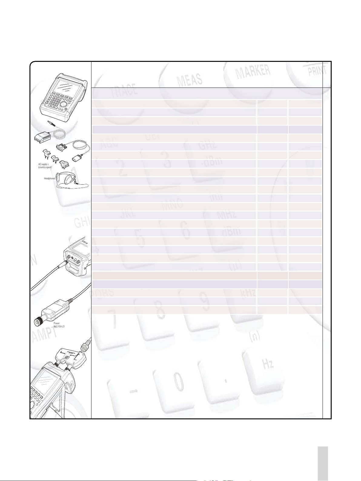
Headphones
RS-232-C cable
AC power supply
AC supply connector
(country-specific)
VSWR Br idge and
Power D ivider R &S FSH-Z2
Power S ensor
R&S FSH -Z1
Power s ensor
connect or on R& S FSH
3
Accessories and ordering information
Ordering information
Designation Type Order No.
Handheld Spectrum Analyzer, 100 kHz to 3 GHz, with preamplifier ¸FSH3 1145.5850.03
Handheld Spectrum Analyzer, 100 kHz to 3 GHz, with tracking generator ¸FSH3 1145.5850.13
Handheld Spectrum Analyzer, 100 kHz to 3 GHz, with tracking generator and preamplifier ¸FSH3 1145.5850.23
Handheld Spectrum Analyzer, 100 kHz to 6 GHz, with preamplifier ¸FSH6 1145.5850.06
Handheld Spectrum Analyzer, 100 kHz to 6 GHz, with tracking generator and preamplifier ¸FSH6 1145.5850.26
Accessories supplied
External power supply, battery pack (built-in), RS-232-C optical cable, headphones, Quick Start manual,
CD-ROM with Control Software ¸FSH View and documentation
Options
Designation Type Order No.
Distance-to-Fault Measurement (includes 1 m cable, ¸FSH-Z2 required) ¸FSH-B1 1145.5750.02
Remote Control via RS-232-C ¸FSH-K1 1157.3458.02
Vector Transmission and Reflection Measurements ¸FSH-K2 1157.3387.02
Receiver Mode ¸FSH-K3 1157.3429.02
Accessories and ordering informationAccessories and ordering information
Handheld Spectrum Analyzer ¸FSH20
Page 12
Headphones
RS-232-C cable
AC power supply
AC supply connector
(country-specific)
VSWR Br idge and
Power D ivider R &S FSH-Z2
Power S ensor
R&S FSH -Z1
Power s ensor
connect or on R& S FSH
3
Optional accessories
Designation Type Order No.
Power Sensor, 10 MHz to 8 GHz ¸FSH-Z1 1155.4505.02
VSWR Bridge and Power Divider, 10 MHz to 3 GHz
(open, short, 50 Ω load)
¸FSH-Z2 1145.5767.02
Directional Power Sensor, 25 MHz to 1 GHz ¸FSH-Z14 1120.6001.02
Power Sensor, 10 MHz to 18 GHz ¸FSH-Z18 1165.1909.02
Directional Power Sensor, 200 MHz to 4 GHz ¸FSH-Z44 1165.2305.02
Matching Pad 50/75
Ω, 0 Hz to 2700 MHz
¸RAZ 0358.5714.02
Spare RF Cable (1 m), connectors N male/N female for ¸FSH-B1 ¸FSH-Z20 1145.5867.02
12 V Car Adapter ¸FSH-Z21 1300.7579.02
Serial/Parallel Converter ¸FSH-Z22 1145.5880.02
Carrying Bag ¸FSH-Z25 1145.5896.02
Transit Case ¸FSH-Z26 1300.7627.02
Combined Short/Open and 50
Ω Load for VSWR and DTF calibration
¸FSH-Z29 1300.7504.02
Spare Short/Open Calibration Standard for ¸FSH-Z2 for VSWR calibration ¸FSH-Z30 1145.5773.02
Spare 50
Ω Load Standard for ¸FSH-Z2 for VSWR and DTF calibration
¸FSH-Z31 1145.5780.02
Spare Battery Pack ¸FSH-Z32 1145.5796.02
Spare AC Power Supply ¸FSH-Z33 1145.5809.02
Spare RS-232-C Optical Cable ¸FSH-Z34 1145.5815.02
Spare CD-ROM with Control Software ¸FSH View and documentation ¸FSH-Z35 1145.5821.02
Spare Headphones ¸FSH-Z36 1145.5838.02
Spare USB Optical Cable ¸FSH-Z37 1300.7733.02
Matching Pad 50/75
Ω, 0 Hz to 1000 MHz
¸FSH-Z38 1300.7740.02
Active Directional Antenna ¸HE200 4050.3509.02
Near-Field Probe Set ¸HZ-15 1147.2736.02
Preamplifier for ¸HZ-15 ¸HZ-16 1147.2720.02
Accessories and ordering information
21Handheld Spectrum Analyzer ¸FSH
 Loading...