

Page 1

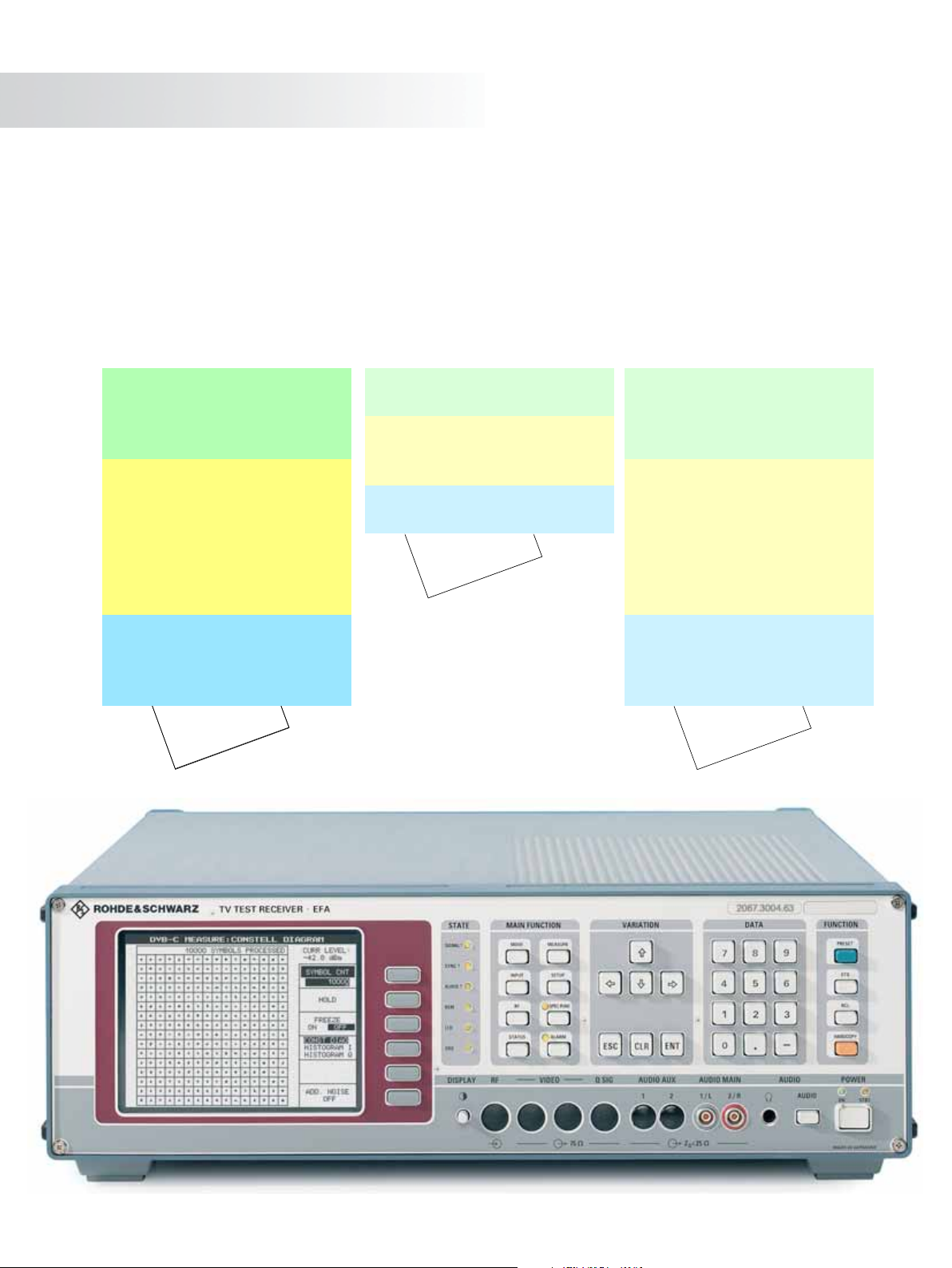
Test Receiver ¸EFA
DVB-C – B/G Analog TV – D/K or I Analog TV
Comprehensive analysis/demodulation/monitoring of digital and analog TV signals in a single unit
Version
05.00
February
2005
◆ Standard test receiver
◆ High-end test receiver
◆ High-end demodulator
◆ Multistandard digital and analog
platform for terrestrial and CATV
applications
◆ Application areas: production,
monitoring, coverage, service,
research and development
◆ Comprehensive measurement and
monitoring functions
◆ Modular design — easy retrofitting of
options
◆ MPEG-2 analyzer/decoder
option for SDTV
◆ IEC/IEEE-bus and RS-232-C interface
◆ Simple, user-friendly operation
Page 2
The ¸EFA Family
The TV Test Receiver and Demodulator Family ¸EFA offers outstanding performance features and excellent transmission characteristics. The instruments provide high-precision reception and demodulation of vestigial sideband AM signals (analog TV signals)
as well as quadrature amplitude modulated DVB signals. They measure a comprehensive range of transmission parameters and are
therefore ideal for measurement and monitoring applications in cable networks, TV transmitter stations and development labs.
The complete ¸EFA family at a glance
Standard test receivers
◆ Model 60: digital TV, DVB-C
◆ Model 12: analog TV, standard B/G
Model 78: analog TV, standard D/K or I
◆
High-end test receivers
◆ Model 63 incl. option ¸EFA-B3:
digital TV, DVB-C
◆ Model 33 incl. option ¸EFA-B3:
analog TV, standard B/G
◆ Model 89 incl. option ¸EFA-B3:
analog TV, standard D/K or I
High-end demodulators
◆ Model 63: digital TV, DVB-C
◆ Model 33: analog TV, standard B/G
Model 89: analog TV, standard D/K or I
◆
t
e
e
h
s
a
t
a
d
s
i
h
T
Standard test receiver
◆ Model 40: digital TV, DVB-T
High-end test receiver
◆ Model 43 incl. option ¸EFA-B3:
digital TV, DVB-T
High-end demodulator
◆ Model 43: digital TV, DVB-T
.
o
N
t
e
2
e
2
h
.
s
4
1
a
t
5
a
5
.
D
7
5
7
0
D
P
Standard test receivers
◆ Model 50: digital TV, ATSC/8VSB
◆ Model 70: digital TV, ITU-T J.83/B
◆ Model 90: analog TV, standard M/N
High-end test receivers
◆ Model 53 incl. option ¸EFA-B3:
digital TV, ATSC/8VSB
◆ Model 73 incl. option ¸EFA-B3:
digital TV, ITU-T J.83/B
◆ Model 93 incl. option ¸EFA-B3:
analog TV, standard M/N
High-end demodulators
◆ Model 53: digital TV, ATSC/8VSB
◆ Model 73: digital TV, ITU-T J.83/B
◆ Model 93: analog TV, standard M/N
.
o
N
t
e
1
e
2
h
.
s
7
1
a
t
0
a
7
.
D
7
5
7
0
D
P
2 Test Receiver ¸EFA
Page 3

Wide variety of models
The family concept described in the
following will help you to find the right
The TV Test Receiver Family ¸EFA
¸EFA model for your application:
from Rohde&Schwarz is a versatile and
high-performance TV test receiver and
◆ If the application mainly involves
demodulator platform, which can be optimally configured for any application,
whether digital or analog.
Three frontends are available:
standard selective
high-end selective
high-end non-selective
The high-end models have a better
signal-to-noise ratio than the standard
models and offer excellent intermodula-
◆ Measurements on modulators or TV
tion characteristics. This, coupled with
minimum inherent frequency response,
ensures extremely accurate measurements.
The ¸EFA model selection concept
measurements in cable networks or
on terrestrial signals, a receiver model
that selects the channel to be measured is the appropriate choice;
adjacent-channel signals, which
impair measurement results, are
filtered out by high suppression; then,
a choice has to be made between the
standard selective and the high-end
selective version; as with the other
criteria, this choice depends on the
application
transmitters, where only one TV
signal is involved, are performed with
one of the demodulator models with
the high-end non-selective frontend,
which ensures extremely low
measurement uncertainty without
preselection
The last selection criterion is the TV standard used, and whether it is analog or
digital:
◆ The ¸EFA test receivers can be
configured for digital signals to the
DVB-C, ATSC/8VSB, ITU-T J.83/B
(¸EFA-B20) or DVB-T
(¸EFA-B10) standard and for
virtually all analog TV standards. For
ATSC/8VSB and ITU-T J.83/B, refer to
data sheet PD 0757.7017; for DVB-T
refer to data sheet PD 0757.5514.
A wide range of options including a
NICAM demodulator (option
¸EFA-B2) and an MPEG-2 decoder (option ¸EFA-B4) complete the
¸EFA product line.
◆ Operation involving a mix of analog
and digital channels is becoming
more widespread especially in cable
networks; this kind of operation is
handled by the QAM demodulator
option for
DVB-C
(¸EFA-B20 + ¸EFA-K21) or
ITU-T J.83/B
(¸EFA-B20 + ¸EFA-K23)
The ¸EFA Family
Standard
test receiver
(Standard selective
frontend)
High-end
demodulator
(High-end non-selective
Digital Demodulator Platform
¸EFA-B20
DVB -C
¸EFA-K21
FIR Coefficient Readout Firmware ¸EFA-K25
ATSC/8VSB ITU-T J.83/B
¸EFA-K22
MPEG-2 Decoder
¸EFA-B4
¸EFA-K23
frontend)
RF Selection
(selective, high quality)
¸EFA-B3
(High-end selective
frontend)
Analog TV demodulators:
Standard B/G (models 12/33)
Standard D/K or I (models 78/89)
NICAM Demodulator
¸EFA-B2-
which adds complete digital measurement functionality to the analog
models.
◆ It is even possible to update to digital
terrestrial applications in accordance
with the ATSC/8VSB standard using
the
ATSC/8VSB demodulator option
(¸EFA-B20 + ¸EFA-K22)
Test Receiver ¸EFA 3
Page 4
The ¸EFA Family
Common to all models
◆ In-depth measurement capabilities
◆ Simple, user-friendly operation
◆ Modular design — easy retrofitting of
options
◆ Alarm messages for measurement
functions, internal storage
◆ Seven alarm-triggered relays for
switching external devices
◆ IEC/IEEE-bus and RS-232-C interface
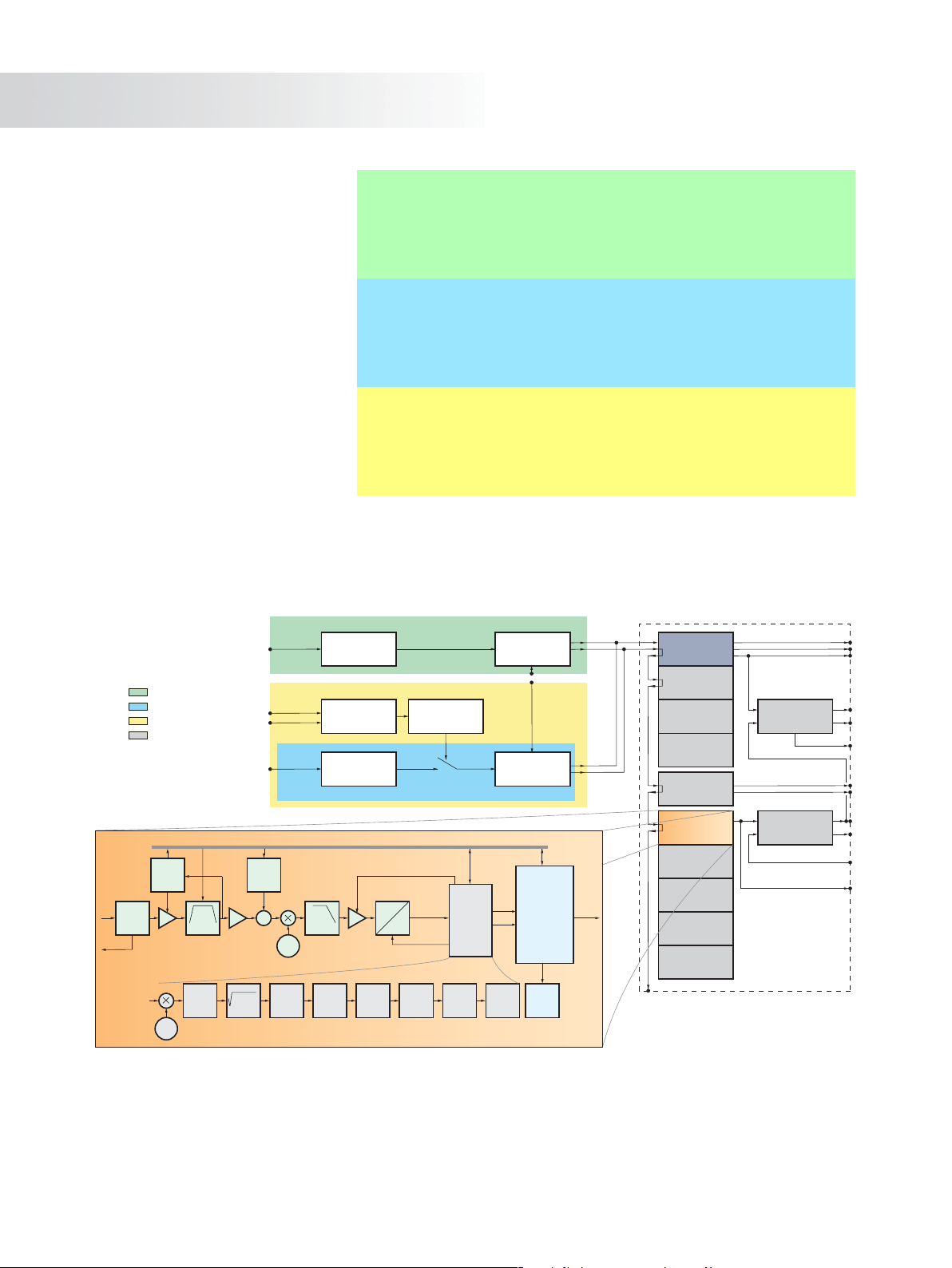
Selective
RF input
50 Ω or 75 Ω
Frontend standard test receiver
Frontend high-end demodulator
Frontend high-end test receiver
Available option
Level
detector
IF
in
Input
stage
IF
out
AGC 1
NCO
SAW
8(/2/6/7) MHz
Synchronization
f
IF,1
=36 MHz
Nyquist
Noise
generator
+
Selective
RF input
50 Ω and 75 Ω
Non-selective
RF input
50 Ω
f
Osc
Osc
Equalizer
LPF
Standard test receiver (¸EFA models 12/60/78)
◆ Selective receiver
◆ Typical use in the field where adjacent channels need to be filtered
◆ High-end synthesizer with low phase noise
◆ Excellent price/performance ratio
High-end demodulator (¸EFA models 33/63/89)
◆ Wideband input (non-selective receiver), tunable
◆ Typically used for transmitter testing
◆ Outstanding SNR, excellent intermodulation characteristics
◆ High-end synthesizer with extremely low phase noise
High-end test receiver (¸EFA models 33/63/89 + option ¸EFA-B3)
◆ Outstanding SNR and improved intermodulation characteristics
◆ Rejection of image frequency and IF
◆ Two additional selective RF inputs (50 Ω and 75 Ω)
◆ Extended frequency range from 4.5 MHz to 1000 MHz
¸EFA models 12/60/78
Attenuator
0 dB to 55 dB
¸EFA models 33/63/89 + optional RF selection (¸EFA-B3)
Trellis
decoder
Attenuator
Attenuator
0…55 dB
0 dB to 55 dB
Attenuator
switch
low/high
Control bus
¸EFA models 33/63/89
AGC 2
A
f
IF,2
Deinter-
leaver
f
CLK
D
Solomon
decoder
Reed-
Selective
transposer
domizer
Multi-
standard
digital
demodulator
QAM/8VSB
Deran-
MPEG-2
interface
Selective
transposer
IF input
Non-selective
transposer
DSP:
Constellation
analyzer
Parameter
analyzer
Ghost pattern
Frequency response
FFT
Amplitude distrib.
History
Display
controller
IF (picture only)
IF
MPEG-2
transport
stream
IF
IF output
Demodulator module, options
Analog TV
demodulator
Std. B/G, D/K or I
Switchable
Sound Trap
¸EFA-B7
Residual picture
carrier measurement
Pilot deviation
measurement
NICAM
Demodulator
¸EFA-B2
Multistandard digital
demodulator
(QAM/8VSB)
6 MHz SAW Filter
¸EFA-B11
7 MHz SAW Filter
¸EFA-B12
8 MHz SAW Filter
¸EFA-B13
2 MHz SAW Filter
¸EFA-B14
Video Distributor
¸EFA-B6
Intercarrier
Audio
MPEG-2 Decoder
¸EFA-B4
MPEG-2 transport
stream input
MPEG-2 transport
stream output
Audio
Video
Video
4 Test Receiver ¸EFA
Block diagram of the TV Test Receiver ¸EFA
Page 5

Digital options
MPEG-2 decoder (option ¸EFA-B4)
◆ MPEG-2 syntax analysis in accordance
with DVB standard ETSI TR 101290
◆ SDTV decoding, 625L or 525L supported,
SDI output, PAL/SECAM/ NTSC video
out
◆ Error report
6 MHz SAW filter (option ¸EFA-B11)
◆ Adjacent-channel rejection
◆ Meets US requirements
7 MHz SAW filter (option ¸EFA-B12)
◆ Adjacent-channel rejection
◆ Meets Cable Australian requirements
¸EFA — realtime signal
analysis of DVB-C signals
The ¸EFA's powerful digital signal
processing provides fast and thorough
analysis of the received DVB-C signal.
Analysis is performed simultaneously
with, but independently of, demodulation and decoding. The MPEG-2 transport stream is permanently available for
decoding as well as for video and audio
reproduction.
Due to its realtime analysis capability,
the high number of measured values
necessary for the complex calculation
and display processes are made available for subsequent mathematical/statistical processing in an extremely short
and as yet unequalled time. Because of
its high-speed data acquisition, the
TV Test Receiver ¸EFA is the ideal
choice, not only for R&D but also for
production environments where short
measurement cycles are essential.
8 MHz SAW filter (option ¸EFA-B13)
◆ Adjacent-channel rejection
◆
Meets European and US standards, recommended for spectrum measurements
2 MHz SAW filter (option ¸EFA-B14)
◆ Adjacent-channel rejection
◆ Meets channel return requirements
(in cable applications)
OFDM demodulator (option
¸EFA-B10)
◆ Retrofit of analog instruments
◆ Support of DVB-T
◆ Included in basic ¸EFA 40/43
models
◆ MPEG-2 transport stream output (serial
and parallel)
For more information, refer to data sheet
PD 0757.5514.
SFN frequency offset measurement
(option ¸EFA-K10)
◆ Unique measurement feature
◆ Indication of frequency offset of each
SFN transmitter
◆ Measurement range from –5 Hz to
+5 Hz
◆ High precision, typ. <0.3 Hz
See data sheet PD 0757.5514.
Digital demodulator platform
(option ¸EFA-B20)
◆ Retrofit of analog instruments
◆ Multistandard demodulator platform
supporting DVB-C demodulation (with
¸EFA-K21), ATSC/8VSB demodula-
tion (with ¸EFA-K22), ITU-T J.83/B
demodulation (with ¸EFA-K23)
◆ Included in basic ¸EFA 50/53/60/
63/70/73 models
◆ MPEG-2 transport stream output
(serial or parallel)
◆ General measurement functions for
–RF input level
– carrier frequency offset
– bit rate offset
– BER (before and after Reed-
Solomon)
DVB-C firmware (option
¸EFA-K21)
◆ Analysis, demodulation and monitor-
ing of DVB-C signals in accordance
with ETS 300 429 standard
◆ Included in basic ¸EFA 60/63
models
ATSC/8VSB firmware (option
¸EFA-K22)
◆ Analysis, demodulation and monitor-
ing of ATSC/8VSB signals in
accordance with ATSC Doc. A/53
◆ Included in basic ¸EFA 50/53
models
◆ Additional SMPTE310M MPEG-2
transport stream output
For more information, refer to data sheet
PD 0757.7017.
ITU-T J.83/B firmware (option
¸EFA-K23)
◆ Analysis, demodulation and monitor-
ing of American digital cable signals
in accordance with ITU-T J.83/B
standard
◆ Included in basic ¸EFA 70/73
models
For more information, please refer to
PD 0757.7017.
FIR coefficient readout firmware
(option ¸EFA-K25)
◆ Calculation of FIR filter coefficients
for linear precorrection of digital
signals
◆
Only available for the ATSC/8VSB
models
The ¸EFA Family
Test Receiver ¸EFA 5
Page 6

The ¸EFA Family
Analog options
NICAM demodulator (option
¸EFA-B2)
◆ Demodulation and decoding of
signals to NICAM-728 standard
◆ I and Q signal output
◆ Switchable deemphasis
◆ Balanced audio outputs
◆ Measurement parameters: bit error
ratio, eye height, clock and data jitter
Video distributor (option ¸EFA-B6)
◆ 2 video outputs on front panel
◆ 2 video outputs on rear panel
◆ 1 additional Q output on front panel
Switchable sound trap (option
¸EFA-B7)
◆ Only available for standard B/G
(¸EFA models 12/33)
M/N NTSC/BTSC demodulator (option
¸EFA-B30)
For more information, refer to data sheet
PD 0757.7017.21.
(Cannot be combined with standard B/G,
D/K or I)
◆ Allows video bandwidth switchover to
6 MHz
Available ¸EFA models and options
Standard test receivers High-end demodulators High-end test receivers
Models ➭ 12 60 78 33 63 89 33 63 89
Option Designation Order No.
¸EFA-B2
¸EFA-B2
NICAM Demodulator
(Standard B/G or D/K)
NICAM Demodulator
(Standard I)
2067.3610.02 ❍ – ❍ ❍ – ❍ ❍ – ❍ 1
2067.3610.04 – – ❍ – – ❍ – – ❍ 1
¸EFA-B3 RF Selection 2067.3627.02 – – – ❍ ❍ ❍ ◆ ◆ ◆ 1
¸EFA-B4 MPEG-2 Decoder 2067.3633.02 ❍
¸EFA-B6 Video Distributor 2067.3656.02 – – – ❍ ❍
¸EFA-B7
Switchable Sound Trap
(Standard B/G)
2067.3710.02 ❍ – – ❍ – – ❍ – – 1
¸EFA-B11 6 MHz SAW Filter 2067.3691.00 ❍
¸EFA-B12 7 MHz SAW Filter 2067.3591.00 ❍
¸EFA-B13 8 MHz SAW Filter 2067.3579.02 ❍
¸EFA-B13 8 MHz SAW Filter 2067.3579.03 ❍
¸EFA-B14 2 MHz SAW Filter 2067.2562.00 ❍
¸EFA-B10 OFDM Demodulator 2067.3740.02 ❍
¸EFA-B20 Digital Demodulator Platform 2067.3585.02 ❍
¸EFA-K10
¸EFA-K21
SFN Frequency Offset
Measurement
DVB-C / J.83/A,C (QAM)
Firmware
2067.9454.02 ❍
2067.4000.02 ❍
¸EFA-K22 ATSC/8VSB Firmware 2067.4017.02 ❍
¸EFA-K23 J.83/B Firmware 2067.4023.02 ❍
¸EFA-K25
¸ZZT-314
FIR Coefficient Readout
Firmware
Carrying Bag for 19" units,
3 HU
2067.4046.02 ❍
1001.0523.00 ❍ ❍ ❍ ❍ ❍ ❍ ❍ ❍ ❍ 0
B/G DVB-C D/K or I B/G DVB-C D/K or I B/G DVB-C D/K or I
1)
❍ ❍
1)3) 9)❍1)3) 9)❍1)3) 9)❍1)3) 9)❍1)3) 9)❍1)3) 9)❍1)3) 9)❍1)3) 9)❍1) 3)9)
1)3) 9)❍1) 3)9)❍1)3) 9)❍1)3) 9)❍1)3) 9)❍1)3) 9)❍1)3) 9)❍1)3) 9)❍1)3) 9)
3)7)
– ❍
3)10)❍3)
3)10)❍3)
6)
– ❍
2)6)
✔ ❍
7)
– ❍
10)
✔ ❍
10)
❍
10)
❍
5)
❍
1)
1)8)
❍
❍ ❍
4)
❍ ❍ ❍
3)7)
3)7)
❍
3)10)❍3)10)❍3)10)❍10) 3)❍3)10)❍3)9)
❍
3)10)❍3)10)❍3)10)❍3)10)❍3)10)❍3)
❍
6)
2)6)
7)
10)
10)
10)
❍
10)
10)
❍
5)
5)
❍
– ❍
6)
❍
– ❍
2)6)
❍
✔ ❍
7)
❍
– ❍
10)
❍
✔ ❍
10)
❍
❍
❍
10)
❍
10)
5)
❍
10)
❍
❍
5)
❍
❍
1)8)
– ❍ – 1
3)7)
❍
6)
❍
2)6)
❍
7)
❍
10)
❍
10)
❍
10)
❍
5)
❍
3)7)
6)
2)6)
7)
10)
10)
10)
5)
4)
– ❍
– ❍
✔ ❍
– ❍
✔ ❍
10)
❍
10)
❍
5)
❍
❍ 0
3)7)03)7)
3)9) 10)
❍
3)10)
❍
6)
2)6)
7)
10)
10)
❍
10)
❍
5)
❍
Slot
needed
0
0
0
0
1
1
0
0
0
0
0
Each base unit has three free slots to take up options.
✔ included in base unit ◆ must be ordered with base unit
1)
Can be retrofitted if option ¸EFA-B10 or ¸EFA-B20 is built in.
2)
Must be ordered with min. one firmware option (¸EFA-K21 or ¸EFA-K22 or ¸EFA-K23).
3)
Max. 3 SAW filters.
4)
Requires ¸EFA-B4.
5)
Can be retrofitted if options ¸EFA-B20 and ¸EFA-K22 are built in. cannot be retrofitted in parallel.
❍
available – not applicable
6)
Only ¸EFA-B10 or -B20 possible (same slot needed).
7)
Can be retrofitted if option ¸EFA-B10 is built in.
8)
Cannot be retrofitted if option ¸EFA-B3 is built in.
9)
¸EFA models 60/63 or ¸EFA-B20: ¸EFA-B11 and ¸EFA-B12
10)
Can be retrofitted if option ¸EFA-B20 is built in.
6 Test Receiver ¸EFA
Page 7
DVB-C
¸EFA models 60/63 — all measurement functions for DVB-C digital CATV standard
Besides digital terrestrial TV and digital
video broadcasting over satellite, digital
cable TV still represents an alternative for
many consumers worldwide. Additionally, cable technology provides a return
channel within the same physical layer
(coax cable), allowing the consumer to
send back information to the cable headend for versatile applications (full Internet access, video-on-demand and more).
Data communications and TV networks
have never been so close!
Characteristics
Fully compatible with the DVB-C standard
(EN 300 429), the ¸EFA 60/63 models
receive, demodulate, decode and analyze
all orders of QAM (quadrature amplitude
modulated) signals. All key parameters
for demodulating the received signal can
be automatically or manually selected:
◆ 4, 16, 32, 64, 128 or 256 QAM
◆ Variable symbol rate for special
modulator tests and lab analysis
(1 Msymbol/s to 6.999 Msymbol/s)
◆ Reed-Solomon error correction
◆ Optional SAW filter bandwidths:
6 MHz, 7 MHz, 8 MHz and 2 MHz
◆ Input of any IF frequency with the aid
of the ¸EFA-B3 option: frequency
range continuously tunable from
5 MHz to 1000 MHz
◆ Special function: invert spectrum
◆ Bit error ratio measurement (before
and after Reed-Solomon decoder)
◆ Integrated noise generator for mea-
surement of noise margin
Features
The test receiver, even the base version,
features a wide range of innovative measurement functions, allowing comprehensive, in-depth signal analysis. In addition to measuring general parameters
(Fig. 1) such as bit error ratio (BER), more
thorough analysis includes:
◆ I/Q constellation diagrams (Fig. 2)
with user-selectable number of symbols to be displayed, range:
1 to 999 999 999 symbols
◆ Histogram I (Fig. 3) and Q (Fig. 4) with
user-selectable number of symbols to
be displayed, range:
1 to 999 999 999 symbols
◆ I/Q parameters, modulation error ratio
(MER), error vector magnitude (EVM),
phase jitter and signal-to-noise ratio
(Fig. 5)
◆ Frequency spectrum (Fig. 6)
◆ Complex channel transmission
function (Fig. 7)
◆ Phase jitter and amplitude jitter spec-
tra (Fig. 8)
◆ Received echo signals (Fig. 9)
◆ Linearity analysis from amplitude dis-
tribution histogram and CCDF
referenced to the RF signal (Figs. 10
and 11)
◆ Eye monitoring (Fig. 12)
◆ History function: long-term monitor-
ing of transmission parameters
(Fig. 13)
◆ Monitoring window (Fig. 14)
◆ Easy configuration of alarm relays
(Fig. 15)
◆ Permanent MPEG-2 transport stream
demodulation (independent of the selected measurement task)
◆ Integrated noise generator
Any failures and degradations are immediately visible in the constellation diagram. Effects of interest can be located
more precisely by varying the number of
symbols represented. The integrated
spectral analysis function enables easy
examination of the signal type and its
spectrum.
DVB-C
Test Receiver ¸EFA 7
Page 8
DVB-C
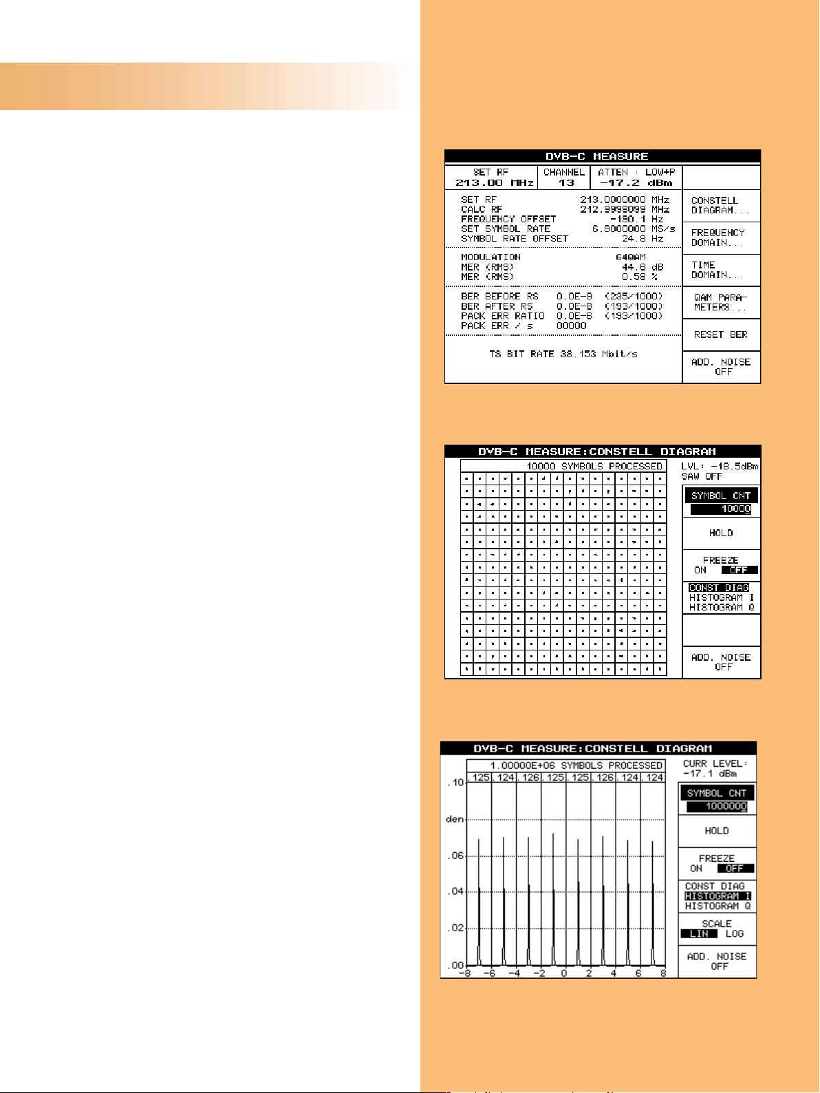
Fig. 1: Measurement menu
All parameters for the demodulated DVB-C channel are displayed
on a single screen and can be checked at a glance:
– Level of the input signal
– Two BERs (bit error ratio) — before and after Reed-Solomon
decoder — provide a fast quality overview of the demodulat-
ed signal
– Demodulated symbol rate
– Symbol rate offset
– Packet errors
Hint: When required, the internal noise generator can be activated to perform END (equivalent noise degradation) or noise
margin measurements based on the BER measurement.
Fig. 2: Constellation diagram
The constellation diagram is always the best way to represent
digital modulation. It is also the best visual tool for interpreting
measurement results such as I/Q amplitude imbalance or carrier
suppression. For in-depth analysis, adjustment of the displayed
number of symbols is possible (10 000 symbols are shown in this
example).
Fig. 3: Histogram I
Histogram I represents the distribution of the quadrature amplitude modulated (QAM) signal on the X axis (I for inphase), and
can be expressed on a linear or logarithmic scale.
It allows an estimate of the interferer's origin (interferer,
Gaussian noise, etc).
Linear scaling is used in this plot.
8 Test Receiver ¸EFA
Page 9

Fig. 4: Histogram Q
Same representation as Fig. 15 — but referring to the distribution of the Q component projected on the X axis (Q for quadrature).
Logarithmic scaling is used in this plot.
Fig. 5: QAM parameters
All QAM parameters are calculated from the constellation diagram:
– I/Q amplitude imbalance
– I/Q phase error
– Carrier suppression
– Phase jitter
– Signal-to-noise ratio
– MER (modulation error ratio), RMS and Min
– EVM (error vector magnitude), RMS and Max
DVB-C
Fig. 6: Spectrum analysis
Owing to this measurement, a separate spectrum analyzer is not
required anymore, e.g. for measuring the shoulder attenuation.
Basic spectrum analyzer functions are provided. For example, the
start/stop frequency (or center/span) and several detection and
averaging modes can be selected.
Test Receiver ¸EFA 9
Page 10

DVB-C
Fig. 7: Amplitude and phase frequency response
The coefficients of the equalizer are used to display the amplitude and phase frequency response (shown here), the group
delay (not shown here) and the polar plot representation.
The polar plot representation — which is the complex representation of amplitude and phase — may help to interpret very short
echoes that are difficult to visualize on the echo pattern display.
Fig. 8: Phase jitter and amplitude jitter spectrum
The R&S EFA‘s QAM function for measuring the phase jitter and
amplitude jitter spectra makes it possible to analyze and monitor
the quality of the various mixer oscillators and amplifier loops of
a transmitter. Jitter analysis can easily be performed during
normal operation without switching off the carrier modulation.
Fig. 9: Echo pattern
The echo pattern measurement allows the main QAM signal
(0 dB relative), echoes and pre-echoes to be visualized and
measured (numeric values).
The units of the X axis and of the numeric values can be changed
from µs to km or even miles, depending on the application.
10 Test Receiver ¸EFA
Page 11

Fig. 10: Amplitude distribution
The measurement function for displaying the amplitude distribution or the CCDF (complementary cumulative distribution function) is used to detect nonlinear distortion.
The frequency distribution of the QAM signal is divided into several 1 dB windows to determine the amplitude distribution. Information on the crest factor is obtained from the frequency distribution and displayed in the upper right-hand corner of the graph.
The reference values are marked by short horizontal lines.
DVB-C
Fig. 11:
Complementary cumulative distribution function (CCDF)
In contrast to the amplitude distribution, each trace point indicates how often a certain voltage level is attained or exceeded.
The ideal frequencies are displayed as short horizontal lines at
1 dB intervals (reference values) so that the amplitude distribution of the applied signal can be compared with that of an ideal
QAM signal. Any deviation from the ideal distribution is then
identified by the deviations of the column heights and the value
of the crest factor, for example due to clipping in the modulator
output stage.
Fig. 12: Eye monitoring
Digitally modulated signals are usually presented in a constellation diagram. This diagram has the disadvantage that it cannot
provide sufficient information on the temporal behavior of
interference.
The unique eye monitoring shows I and Q components versus
time. With eye monitoring, 100% of the symbols are captured
and displayed. Thus, in the case of impulsive interferers or longterm effect, all undesired signals are captured and displayed.
Test Receiver ¸EFA 11
Page 12

DVB-C
Fig. 13: History function
This measurement is just what is required for long-term monitoring of modulators in cable headends.
The key parameters (level, synchronization information, MER/dB,
MER/%, EVM/%, BER before and after Reed-Solomon decoder,
synchronization and MPEG-2 transport stream data error) are,
therefore, displayed in graphical form. This mode can also display all values numerically (average, max, min, current). BER and
level measurements run continuously and are independent of
other measurements. The user can configure a monitoring interval from 60 seconds (shown here) to 1000 days.
Fig. 14: Monitoring/Alarm register
The ¸EFA checks the input level (LV), QAM synchronization
(SY), modulation error ratio (ME), error vector magnitude (EV), bit
error ratio before Reed-Solomon decoder (BR) and MPEG-2 data
errors (DE) of the DVB-C signal once per second.
All alarm messages are stored in the alarm register together with
the date and time.
Up to 1000 entries can be stored.
Fig. 15: Configuration of alarm relays
Alarms can be signaled via seven integrated relays. An assignment table is available for configuring the alarm relays.
12 Test Receiver ¸EFA
Page 13

Typical applications
¸EFA for production of modulators
The ¸EFA‘s analysis capabilities permit in-depth testing of the cable modulator's performance due to the outstanding
MER/EVM dynamic range, amplitude distribution measurement and spectrum
analysis. Another feature is the Equalizer
ON/FREEZE/OFF function, which is mandatory during the alignment phase of
modulators. Finally, the high accuracy
and repeatability of the measurements
makes the ¸EFA ideally suited for the
production of QAM modulators.
Cable headend monitoring
The capability of the ¸EFA to handle
multichannel reception with the spectrum measurement and the history functions (graphical measurement representation versus time) permits the instrument to monitor cable headends. In addition, an alarm is triggered if one of the
selected parameters exceeds the set
threshold (all thresholds can be individually configured). Incident level, QAM synchronization, MER (modulation error
ratio), EVM (error vector magnitude), BER
before Reed-Solomon decoder and
MPEG-2 transport stream data error can
be checked in realtime independently of
other measurements and decoding. If an
error occurs, a 1000line
register is available for recording the
date, time and
description of the
event.
¸EFA in
research and development laboratories
Owing to the highquality frontend
design, the dynamic
range of the modulation error ratio measurement (MER
dynamic range better than 41 dB) allows
the instrument to be used as a reference
demodulator in research and development laboratories.
¸EFA as a multistandard digital
and analog platform
Since the analog standards B/G, D/K and I
are still used in cable networks, and cable
operators need a future-proof solution for
their short- and long-term investment,
the digital DVB-C demodulator option can
be implemented in the analog units. It
covers all application areas from R&D to
cable headend measurements. Furthermore, to protect your investment, the
instrument can be updated by means of
options to demodulate and analyze the
ITU-T J.83/B cable standard as well as
the digital terrestrial standards ATSC/
8VSB and DVB-T. These unique features
make the new ¸EFA family members
THE measurement devices for the present
and the future.
DVB-C
DVB-C application
Production of modulators
Cable headend monitoring
Research and development
Service
! most important measurement
Summary of measurements required for the various DVB-C applications
Level
BER
I/Q parameters
SNR
Phase jitter
Phase jitter and amplitude
jitter spectra
MER/EVM
✔ ✔ ✔ ✔ ✔ ✔
✔ ✔ ✔
✔ ✔ ✔ ✔ ✔ ✔ ✔ ✔
✔ ✔ ✔ ✔
✔
required measurement
!
Eye monitoring
Constellation diagram
Histograms
Frequency spectrum
Amplitude (f) – phase (f) –
group delay (f)
✔ ✔ ✔ ✔ ✔
✔ ✔ ✔
!
✔ ✔ ✔ ✔ ✔
!
! !
✔ ✔ ✔ ✔
Amplitude distribution –
CCDF
Echo pattern
History
!
Test Receiver ¸EFA 13
Alarm
✔ ✔
Statistics
Page 14

Analog TV
¸EFA models 12/33/78/89 — analog TV test receivers
Since the analog terrestrial standards
B/G, D/K and I are still commonly in use,
and broadcasters need a future-proof
solution for their short- and long-term
investment, Rohde & Schwarz provides
a high-end measurement device that can
cover all application areas from R&D to
field measurements. This ¸EFA
model was created to offer the best performance and the most useful features to
test standard B/G, D/K and I transmitters
under optimal conditions.
To further protect your investment, the
instrument can be updated by means of
options to demodulate and analyze the
digital CATV standards DVB-C (option
¸EFA-K21) and ITU-T J.83/B (option
¸EFA-K23) as well as the digital terrestrial standards ATSC/8VSB (option
¸EFA-K22) and DVB-T (option
¸EFA-B10). These unique features
make the ¸EFA models THE measurement devices for the present and the
future!
Characteristics of the analog
¸EFA models 12/33/78/89
Fully compatible with analog standards,
the analog ¸EFA models receive and
demodulate most analog TV standards
(B/G, D/K and I). All key parameters for
demodulating the received signal can be
automatically or manually selected:
◆ Switchable group delay correction
◆ Switchable synchronous detector
(5 different modes)
◆ Demodulation using intercarrier
method
◆ Balanced audio outputs
◆ Measurement functions for
– vision/sound carrier spacing (level
and frequency)
– FM sound carrier and pilot
deviation
– Residual picture carrier (RPC) or
video modulation depth
◆ Input of any IF frequency with the aid
of the ¸EFA-B3 option: frequency
range continuously tunable from
5 MHz to 1000 MHz
Features
The analog ¸EFA models provide
high-precision demodulated baseband
signals (vision and sound) for measurements in various applications (TV transmitters, cable headends, coverage measurements, R&D). At the same time, all
relevant RF parameters are monitored at
high speed and represented in a logical
manner (Fig. 16). User-configurable
alarm messages permit unattended monitoring of the received signals as well as
switchover to alternative links in the
event of a failure.
The high-end demodulator version is
used for on-site measurements on TV
transmitters. This version offers particularly low-distortion demodulation of the
broadcast signal. It is perfectly suited for
these types of measurements; its low
measurement uncertainty permits optimal alignment as well as permanent
quality control of transmitters.
Fig. 16: Measurement window
All parameters for the demodulated standard B/G TV channel are
displayed on a single screen and can be checked at a glance:
– Vision carrier level
– Video modulation depth
– Sound intercarrier measurements
– Vision/sound level ratio
– Sound 1&2 FM deviation
– Pilot decoding
14 Test Receiver ¸EFA
Page 15

Specification of intermodulation
In-channel distortion
In-channel distortion is determined by
means of a modulated TV signal with a
vision carrier (f
and a sound carrier (f
), a color subcarrier (fSB)
VC
). Modulation is
SC
selected such that the vision carrier is
lowered by 6 dB, the color subcarrier by
14 dB and the sound carrier by 10 dB relative to the sync pulse level. The level of
the intermodulation product is measured
at the video output relative to the blackto-white transition of the video signal.
Fig. 17 shows the signals involved and
the reference level at the RF.
RF
input level
0 dB
−6 dB
16 dB
Out-of-channel distortion
The effect of signals outside the received
channel is described by the 3rd order
intercept point (TOI). For the ¸EFA
family, this parameter is specified on the
basis of a three-tone measurement with
the following signals: a wanted carrier at
the receive frequency f
and two
VC
unwanted carriers 14 MHz and 15 MHz
above the receive frequency.
Sync level
−10 dB
−14 dB
Sideband level for
alternating black and
white modulation
The selected unwanted frequencies are
within the bandwidth of the RF selection
but outside the bandwidth of the first IF
filter. The effect of out-of-channel interference on the receiver can thus reliably
be determined. It is assumed that each of
the three signals has the same RF input
level P. The level of the intermodulation
product ∆IM 1 MHz relative to the
wanted carrier is measured (see Fig. 18,
measurement at the RF). The 3rd order
intercept point is as follows:
dBm = P/dBm +
TOI
/
∆IMIdB
----------------------2
+
3
RF
input level
∆
IM
Analog TV
f
VCfIM
P
fVCf
fSBf
IF filter
∆
IM
SC
RF filter
IM
f
f
VC
VC +15 MHz
+14 MHz
f
Fig. 17
f
Fig. 18
Test Receiver ¸EFA 15
Page 16

Specifications
DVB-C characteristics (specific to ¸EFA models 60/63 or options ¸EFA-B20 + ¸EFA-K21)
Standard test receiver High-end test receiver
High-end demodulator
with option ¸EFA-B3
RF input selective selective
Connector 50 Ω or 75 Ω, BNC or N female, front or
rear panel
Return loss ≥14 dB in channel with 50 Ω connector
and input attenuation ≥10 dB
≥12 dB in channel with 75 Ω connector
and input attenuation ≥10 dB
Frequency range
Level range
2)
4)
48 MHz to 862 MHz 4.5 MHz3) to 1000 MHz
–55 dBm to +20 dBm
(low distorsion, preamplifier off)
–59 dBm to +20 dBm
(low noise, preamplifier off)
–64 dBm to +13 dBm
(low noise, preamplifier on)
Noise figure typ. 12 dB (low noise)
typ. 7 dB (low noise, preamplifier on)
1)
50 Ω, N female, rear panel and 75 Ω,
BNC female, rear panel
≥17 dB (typ. >20 dB) in channel
with 50 Ω connector
≥14 dB (typ. >17 dB) in channel
with 75 Ω connector
–63 dBm to +20 dBm5)
(normal)
–62 dBm to +20 dBm
(low distorsion)
–65 dBm to +16 dBm
5)
5)
(low noise)
typ. 7 dB (low noise)
typ. 9 dB (normal)
typ. 11 dB (low distortion)
6)
6)
6)
non-selective
50 Ω, N female, rear panel
≥30 dB
45 MHz to 1000 MHz
–50 dBm to +20 dBm
Image frequency rejection ≥70 dB (VHF) and ≥50 dB (UHF) 100 dB
IF rejection 100 dB
Local oscillator
Resolution 1 Hz 1 Hz 1 Hz
Frequency error ≤2 x 10
Phase noise
SSB phase noise
(RF= 860 MHz)
7)
≥50 dB ≥58 dB ≥62 dB
≤–82 dBc/Hz, typ. ≤–86 dBc/Hz at 1 kHz
≤–93 dBc/Hz, typ. ≤–98 dBc/Hz at 20 kHz
−6
−6
≤2 x 10
≤–93 dBc/Hz, typ. ≤–98 dBc/Hz at 1 kHz
≤–98 dBc/Hz, typ. ≤–102 dBc/Hz at 20 kHz
≤2 x 10
≤–100 dBc/Hz, typ. ≤–104 dBc/Hz at 1 kHz
≤–105 dBc/Hz, typ. ≤–110 dBc/Hz at 20 kHz
System performance
equalizer on equalizer off
MER ≥40 dB
EVM ≤0.66%
SNR ≥42 dB
9)
9)
9)
≥41 dB
≤0.59 %
≥43 dB
10)
10)
10)
≥42 dB
≤0.52 %
≥44 dB
−6
8)
11)
11)
11)
typ. ≥40 dB
≤0.65 %
typ. ≥40 dB
1)
The selective RF inputs of the high-end TV test receiver (with option ¸EFA-B3) are additional to the non-selective RF input of the high-end demodulator. For specifications involving the non-selective RF
input, see the high-end demodulator column.
2)
Center frequency.
3)
For frequencies <10 MHz: group delay tilt increases up to 200 ns, amplitude tilt increases up to typ. 0.7 dB pp, minimum input level: –30 dBm, SAW filter ON.
4)
For quasi error-free MPEG-2 transport stream, 256 QAM.
5)
At l ow in put f requ enci es su ch as 4.57 MHz: addi tion al ti lt ( typ. 0.7 dB pp), minimum input level: –30 dBm, SAW filter ON.
6)
RF >47.15 MHz.
7)
FM S/N ratio measured at IF output, referenced to ±30 kHz frequency deviation and 500 Hz modulation frequency, deemphasis 50 µs, measured to DIN45405, weighted to ITU-R468-3.
8)
In frequency range 45 MHz to 900 MHz.
9)
Signal power > –40 dBm.
10)
Signal power > –43 dBm.
11)
Signal power > –30 dBm.
16 Test Receiver ¸EFA
Page 17

DVB-C characteristics (continued)
IF input
Return loss
Center frequency
Level range
IF output
Return loss
Center frequency
Level, regulated
10 MHz reference input
Level range
10 MHz reference output
Level
50 Ω, BNC female, rear panel
≥20 dB in channel
36 MHz
–30 dBm to –5 dBm
50 Ω, BNC female, rear panel
≥20 dB in channel
36 MHz
–17 dBm
50 Ω, BNC female, rear panel
–20 dBm to +16 dBm
50 Ω, BNC female, rear panel
typ. +11 dBm
MPEG-2 TS parallel output LVDS (188 bytes/204 bytes)
MPEG-2 TS ASI output
Symbol rate
Bandwidth (SAW filter)
Channel correction
Modulation mode
Measurements signal power
Graphic displays constellation diagram
serial MPEG-2 transport stream (ASI); 75 Ω
1 Msymbol/s to 6.999 Msymbol/s
2 MHz, 7 MHz, 6 MHz, 8 MHz or SAW filter OFF
self-adapting equalizer, equalizer freeze, equalizer off
4/16/32/64/128/256 QAM
packet errors/s (J.83/A,C)
carrier frequency offset
symbol rate offset
MPEG-2 TS bit rate
BER (bit error ratio) before and
after Reed-Solomon decoder
segment error ratio (J.83/B)
segment errors/s (J.83/B)
EVM (error vector magnitude)
MER (modulation error ratio)
SNR (signal/noise ratio)
packet error ratio (J.83/A,C)
phase jitter spectrum
histogram I/Q
frequency spectrum
amplitude frequency response
phase frequency response
amplitude jitter spectrum
group delay frequency response
polar plot
echo pattern
phase jitter
I/Q amplitude imbalance
I/Q quadrature error
carrier suppression
crest factor
shoulder attenuation in accordance with ETSI TR 101290
amplitude distribution (RF)
CCDF (RF)
CCDF (ENV)
eye monitoring
history
Alarm messages signal power, MPEG-2 synchronization, EVM, MER, BER before Reed-Solomon decoder, MPEG-2 data er-
ror
Storage alarm message with date and time, up to 1000 messages
Memory for instrument setup storage 0 to 4
Test parameters Range Resolution Error
Signal power corresponding to level range 0.1 dB <3 dB, typ. <1 dB
MER dB (modulation error ratio in dB) 18 dB to 30 dB
30 dB to 35 dB
MER % (modulation error ratio in %) 1.9% to 3.2%
3.2% to 12.5 %
EVM (error vector magnitude) 1.17% to 2.07 %
2.07% to 8.3 %
SNR (signal/noise ratio) 18 dB to 30 dB
30 dB to 35 dB
0.1 dB
0.1 dB
0.01%
0.01%
0.01%
0.01%
0.1 dB
0.1 dB
≤0.8 dB
≤1.0 dB
≤12% of actual value
≤10% of actual value
≤12% of actual value
≤10% of actual value
≤0.5 dB
≤0.8 dB
I/Q amplitude imbalance 0.00 % to 5.00% 0.01% ≤0.03 dB
I/Q quadrature error 0.00 ° to 5.00 ° 0.01° ≤0.03°
Carrier suppression 25 dB to 45 dB
45 dB to 60 dB
Carrier frequency offset
10 MHz reference, internal
10 MHz reference, external
±100 kHz
±100 kHz
1)
1)
0.1 dB
0.1 dB
0.1 Hz
0.1 Hz
≤1 dB
≤3 dB
≤280 Hz + 2 ppm × RF
≤1 Hz
Symbol rate offset
10 MHz reference, internal
10 MHz reference, external
±1000 Hz
±1000 Hz
0.1 Hz
0.1 Hz
<7 Hz
≤0.5 Hz
MPEG-2 TS bit rate up to 51.600 Mbit/s 1 kbit/s <1 kbit/s
BER before Reed-Solomon 1.0 × 10⁻³ to 0.1 × 10
BER after Reed-Solomon 1.0 × 10⁻⁵ to 0.1 × 10
1)
For symbol rate ≥ 5 Msymbol/s.
−15
−14
0.1 × 10
0.1 × 10
−exponent
−exponent
–
–
Specifications
Test Receiver ¸EFA 17
Page 18

Specifications
Analog TV, model-specific characteristics
Standard test receivers
models 12/78
High-end test receivers
models 33/89
High-end demodulators
models 33/89
RF input selective selective non-selective
Connector 50 Ω or 75 Ω, BNC or N female, front or
rear panel
Return loss ≥14 dB in channel with 50 Ω connector
and input attenuation ≥10 dB
≥12 dB in channel with 75 Ω connector
and input attenuation ≥10 dB
Frequency range (vision carrier) 48 MHz to 860 MHz 5 MHz1) to 1000 MHz
Level range
2)
–67 dBm to +13 dBm (normal)
–77 dBm to –47 dBm (with preamplifier)
Image frequency rejection VHF: ≥70 dB4) UHF: ≥50 dB4)
IF rejection 100 dB
50 Ω, N female, rear panel and 75 Ω,
BNC female, rear panel
≥17 dB (typ. >20 dB) in channel
with 50 Ω connector
≥14 dB (typ. >17 dB) in channel
with 75 Ω connector
–67 dBm to +21 dBm3) (normal)
–67 dBm to +21 dBm
–77 dBm to +21 dBm
5)
100 dB
5)
3)
(low distortion)
3)
(low noise)
50 Ω, N female, rear panel
≥30 dB
45 MHz to 1000 MHz
–41 dBm to +21 dBm
Local oscillator
Resolution 1 Hz 1 Hz 1 Hz
Frequency error ≤2 x 10
Phase noise
1)
For frequencies <10 MHz: group delay tilt increases up to 200 ns, amplitude tilt increases up to typ. 0.7 dB pp, minimum input level: –30 dBm, SAW filter ON; upper sideband.
2)
Levels are rms values referenced to sync pulse.
3)
In receive frequency range 5MHz to 15 MHz: –41 dBm to 21 dBm.
4)
Image frequency of vision carrier.
5)
Applies to both frequency conversions.
6)
FM S/N ratio measured at IF output, referencSed to ±30 kHz frequency deviation and 500 Hz modulation frequency, deemphasis 50 µs, measured to DIN45405, weighted to ITU-R468-3.
7)
In receive frequency range 45 MHz to 900 MHz.
6)
−6
≥50 dB ≥58 dB ≥62 dB
≤2 x 10
−6
≤2 x 10
−6
7)
0
in dB
A
rel
–10
frequency threshold
–20
–30
–40
–50
0.5 MHz 0 dB (reference)
0 to 4.5 MHz model-specific,
4.8 MHz >−3 dB
5.0 MHz >−26 dB
5.4 MHz to 5.85 MHz <−50 dB
>5.4 MHz <−48 dB
12345
see page 19
A
rel
Standard
B/G, I (CATV)
f in MHz
7
6
0
in dB
–10
frequency threshold
0.5 MHz 0 dB (reference)
0 to 5.0 MHz model-specific,
–20
5.9 MHz to 6.9 MHz >−50 dB
–30
6,9 MHz to 7.9 MHz >−45 dB
7.9 MHz to 8.1 MHz <−50 dB
–40
>8.1 MHz <−45 dB
–50
1
2345
A
rel
–10
–20
–30
–40
see page 19
0
in dB
Standard D/K
frequency threshold
0.5 MHz 0 dB (reference)
0 to 5.5 MHz model-specific,
6.1 MHz to 6.9 MHz <−48 dB
>6.9 MHz >−46 dB
–50
1
Standard I
(terrestrial)
7
6
see page 19
2345
f in MHz
8
f in MHz
8
7
6
Tolerance masks of the ¸EFA for total amplitude characteristic (RF, IF, VF)
18 Test Receiver ¸EFA
Page 19

Analog TV, model-specific characteristics (continued)
Standard test receivers
Models 12/78
High-end test receivers
Models 33/89
High-end demodulators
Models 33/89
Video demodulation characteristics
Noise voltage, ref. to b/w transition P
S/N
unweighted ≥60 dB, typ. 63 dB
rms
S/N
weighted to ITU-R Rec. 567 ≥60 dB, typ. 64 dB (low noise)
rms
Signal/hum
peak
≥ −30 dBm, 0 dB input attenuation P
RF
= −33 dBm, 0 dB input attenuation P
RF
≥64 dB, typ. 66 dB (low noise)
≥ −1 dBm
RF
≥67 dB, typ. 70 dB
≥63 dB, typ. 65 dB (normal)
≥57 dB, typ. 59 dB (
low distortion)
≥62 dB, ,typ. 64 dB (low distortion)
≥52 dB ≥52 dB ≥52 dB
Linear distortion
Amplitude frequency response
DC to color subcarrier
Additional ripple through SAW filter
reference: 0.5 MHz
≤0.5 dB
≤0.1 dB
reference: 0.5 MHz
≤0.35 dB
≤0.1 dB
reference: 0.5 MHz
≤0.25 dB
≤0.1 dB
Group delay response reference: 0.1 MHz reference: 0.1 MHz reference: 0.1 MHz
With constant group delay ≤20 ns ≤15 ns ≤12 ns
With group delay dep. on TV std. see group-delay table see group-delay table see group-delay table
Additional ripple through SAW filter ≤10 ns ≤10 ns ≤10 ns
B/G D/K I K1
General
Group delay/ns
Frequency/MHz
Sweden
Norway
Denmark
Australia
General/2
(reduced to 50%)
New Zealand
ITU-R Report 308
OIRT
TK-III-830
OIRT
GOST
20532-75
GOST
20532-83
CSFR
SABC
TVT 12.2
0.10 0 0 0 0 0 0 0 0 0 0 0 0 0 0
0.25 −5 ±∆ 0 ±∆ 0 ±∆ −5 ±∆ −2.5 ±∆ −5 ±∆ −5 ±∆ 0 ±∆ 0 ±∆
0.50 0 ±∆ 0 ±∆ −10 ±∆ −8 ±∆ 0 ±∆ 0 ±∆
1.00 −53 ±∆ 0 ±∆ 0 ±∆ −53 ±∆ −30 ±∆ −26.5 ±∆ −53 ±∆ −40 ±∆ −40 ±∆ −40 ±∆ −40 ±∆ 0 ±∆ 0 ±∆
1.50 0 ±∆ 0 ±∆ −70 ±∆ 0 ±∆ 0 ±∆
2.00 −90 ±∆ 0 ±∆ 0 ±∆ −75 ±∆ −60 ±∆ −45 ±∆ −87 ±∆ −75 ±∆ −80 ±∆ −85 ±∆ −85 ±∆ 0 ±∆ 0 ±∆
2.25 0 ±∆ 0 ±∆ −60 ±∆ 0 ±∆ 0 ±∆
3.00 −75 ±∆ 0 ±∆ 0 ±∆ −75 ±∆ −40 ±∆ −37.5 ±∆ −60 ±∆ −85 ±∆ −90 ±∆ −80 ±∆ −92 ±∆ −90 ±∆ 0 ±∆ 0 ±∆
3.50 0 ±∆ 0 ±∆ 0 ±∆ 0 ±∆
3.58 0 ±∆ 0 ±∆ 0 ±∆
3.60 0 ±∆ 20 ±∆ 0 ±∆ 0 ±∆
3.75 0 ±∆ 0 ±∆ 0 ±∆ 0 ±∆ 0 ±∆
3.80 0 ±∆ 0 ±∆ 0 ±∆
4.00 50 ±20 −50 ±20 −70 ±20 −40 ±20 −60 ±20 −60 ±20 0 ±∆ 0 ±∆
4.43 170 ±20 175 ±20 170 ±20 170 ±20 170 ±20 85 ±20 170 ±20 0 ±20 0 ±20 −25 ±20 −25 ±20 40 ±20 15 ±20
4.70 0 ±20 0 ±20
4.80 400 ±40 400 ±40 350 ±40 400 ±40 260 ±40 200 ±40 400 ±40 100 ±40
5.00 90 ±20 0 ±20 80 ±20 70 ±20 90 ±20
5.50 90 ±20 260 ±40
High-end demodulator: ∆ = 12 ns
High-end test receiver: ∆ = 15 ns
Standard test receiver: ∆ = 20 ns
Group delay depending on TV standard
Specifications
Test Receiver ¸EFA 19
Page 20

Specifications
Analog TV, model-specific characteristics (continued)
Video demodulation characteristics
(continued)
Transient response
2T pulse k factor ≤1% ≤1%, typ. 0.6 % ≤1%, typ. 0.6 %
2T pulse amplitude error ≤2%, typ. 1%
20T pulse amplitude error ≤3% (TV standards B/G, D/K, I)
12.5T pulse amplitude error ≤5% (TV standard M/N)
Chrominance/luminance gain ≤3%
Chrominance/luminance delay ≤20 ns (with constant group delay) ≤15 ns (with constant group delay) ≤12 ns (with constant group delay)
Tilt, 10/75% modulation ≤1% (15 kHz squarew. signal, T
Nonlinear distortion
Luminance nonlinearity ≤2%, typ. 0.3% ≤2%, typ. 0.3% ≤2 %, typ. 0.4%
Differential gain ≤2%, typ. 0.3% ≤2%, typ. 0.3% ≤2 %, typ. 0.4%
Differential phase ≤1 °, typ. 0.4° ≤1 °, typ. 0.4° ≤1 °, typ. 0.5 °
Intermodulation in channel, referenced
to b/w transition
3rd order intercept point;
0 dB attenuation
(see also page 15)
Standard test receivers
models 12/78
≤20 ns (with group delay dep. on TV std.) ≤20 ns (with group delay dep. on TV std.) ≤20 ns (with group delay dep. on TV std.)
rise
≥52 dB, typ. 56 dB (low noise)
≥62 dB, typ. 66 dB (l
≥0 dBm (low noise)
≥5 dBm (low distortion)
ow distortion)
High-end test receivers
models 33/89
200 ns) ≤1 % (15 kHz squarew. signal, T
≥57 dB, typ. 61 dB (normal)
≥52 dB, typ. 56 dB (low noise)
≥62 dB, typ. 66 dB (low distortion)
≥10 dBm (normal)
≥14 dBm (low distortion)
High-end demodulators
models 33/89
200 ns) ≤1 % (0.25 Hz squarew. signal, T
rise
≤1% (50 Hz squarew. signal, T
≤1% (15 kHz squarew. signal, T
≥55 dB
rise
rise
rise
2 µs)
2 µs)
200 ns)
Characteristics common to all analog models
IF input 50 Ω, BNC female, rear panel
Vision carrier frequency
TV standards B/G, I, D/K 38.9 MHz
Return loss in channel ≥30 dB
Level range
Crosstalk attenuation, RF/IF input ≥75 dB
IF output 50 Ω, BNC female, rear panel
Return loss in channel ≥20 dB
Vision carrier level1), regulated −7 dBm
Input for external zero reference 75 Ω, BNC female, rear panel
Control voltage >1 V
Delay of carrier blanking relative to control pulse <3 µs
Video selectivity
1)
Levels are rms values referenced to sync pulse.
1)
In-channel sound carrier suppression
TV standard B/G, I
D/K
Adjacent-channel vision carrier suppression
TV standard B/G, I (CATV)
I (terrestrial)
D/K
−13 dBm to 4 dBm
≥50 dB
≥48 dB
≥50 dB
≥48 dB
≥46 dB
20 Test Receiver ¸EFA
Page 21

Characteristics common to all analog models (continued)
Video outputs 75 Ω, BNC female, front panel and
Return loss (0 to 6 MHz) ≥26 dB
Decoupling of outputs
Level variation at terminated output with other output short-circuited or open
Video level, adjustable 1 V pp ±3 dB
Level inaccuracy ≤2%
Resolution of level control 10 mV
DC offset with carrier clamped to zero level 0 V ±20 mV
Quadrature signal output of sync demodulator 75 Ω, BNC female, on rear panel
Return loss (0 to 6 MHz) ≥20 dB
Gain difference, referenced to nominal video output level ≤0.5 dB
Synchronous demodulation
Phase error of switching carrier ≤1°
Vision carrier phase control continuous, sampled (switchable)
Time constant of PLL for keyed phase control normal, slow (switchable)
Time constant of PLL for continuous phase control fast, normal, slow (switchable)
Sound demodulation intercarrier method
Audio outputs Lemo Triax female, in pairs
Output signal M1/L and M2/R
Permissible load ≥300 Ω // ≤5000 pF
Audio level, adjustable
Reference frequency deviation ±30 kHz or ±50 kHz, selectable
Setting range for ±30 kHz reference frequency deviation −3 dBm to +10 dBm
Setting range for ±50 kHz reference frequency deviation +2 dBm to +10 dBm
Resolution of level control 0.1 dB
Level accuracy, f
Amplitude frequency response, 40 Hz to 15 kHz, referenced to 500 Hz ≤±0.3 dB
Deemphasis 50 µs, can be switched off
Distortion at ±50 kHz frequency deviation, deemphasis on ≤0.5 %
S/N ratio (intercarrier method)
Referenced to ±30 kHz frequency deviation and 500 Hz modulation frequency, measured to DIN45405, weighted to ITU-R468-3; the channel not being measured
is without signal
Vision modulation: all-black picture ≥55 dB
Vision modulation: test pattern ≥48 dB
Vision modulation: sinewave, 10% to 75% modulation ≥46 dB
Vision modulation: sinewave, 242 kHz ±15 kHz, 10% to 75% modulation ≥42 dB
Stereo crosstalk, 40 Hz to 15 kHz
Referenced to ±30 kHz frequency deviation and 500 Hz modulation
frequency, deemphasis on
Channel crosstalk, 40 Hz to 15 kHz
Referenced to ±30 kHz frequency deviation, deemphasis on,
measured with ±30 kHz spurious FM
Alarm message
Vision carrier level, RF offset, TV synchronization, vision/FM sound carrier level ratios, vision/FM sound carrier frequency spacings, FM pilot deviation,
max. FM deviations, min. FM deviations
500 Hz ≤0.2 dB
mod
75 Ω, BNC female, real panel
≤1%
rear panel: balanced, Z <35 Ω
front panel: unbalanced, Z <10 Ω
≥40 dB
≥74 dB
Test parameters, analog TV
Measurement range Resolution Error
Vision carrier power or voltage in µV/mV,
dBµV, dBmV, dBm, dBµW, dBpW
Standard test receivers −77 dBm to 13 dBm 0.1 dB ≤3 dB
High-end test receivers −77 dBm to 21 dBm 0.1 dB ≤3 dB
High-end demodulators −41 dBm to 21 dBm 0.1 dB ≤2 dB
Video level (CVS0) 50% to 150% 1% ≤2%
Specifications
Test Receiver ¸EFA 21
Page 22

Specifications
Test parameters, analog TV (continued)
Measurement range Resolution Error
Vision carrier frequency frequency range depending on
Vision/FM sound carrier 1 level ratio −23 dB to −7 dB 0.1 dB ≤2 dB
Vision/FM sound carrier 2 level ratio −30 dB to −14 dB 0.1 dB ≤2 dB
Vision/FM sound carrier 1 frequency
spacing
Vision/FM sound carrier 2 frequency
spacing
FM sound carrier deviation 0 kHz to 80 kHz 100 Hz ≤3% ±200 Hz
FM pilot carrier deviation (average) 1 kHz to 5 kHz 10 Hz ≤5%
FM pilot carrier deviation (peak value) 1 kHz to 10 kHz 10 Hz ≤5%
Pilot frequency pilot frequency ±300 Hz 2 Hz ≤2 Hz
Residual AM 0% to 30% 0.1% 0.5%
Modulation depth of vision carrier 70% to 100 % 0.1% 0.5%
1)
With unmodulated sound carrier.
2)
Without vision modulation.
¸EFA model
nominal IC frequency ±50 kHz 100 Hz ≤200 Hz
nominal IC frequency ±50 kHz 100 Hz ≤200 Hz
20 Hz ≤2 ×10
−6
Options
NICAM Demodulator ¸EFA-B2
Standard NICAM-728
NICAM IF carrier frequency standard B/G 33.05 MHz
standard I 32.348 MHz
Vision/NICAM carrier level ratio 15 dB to 31 dB
FM sound carrier suppression ≥40 dB
Frequency response deviation from standard curve up to 182 kHz ≤1 dB
Group delay up to 120 kHz ≤150 ns
Group delay up to 182 kHz ≤200 ns
NICAM intercarrier input 50 Ω, BNC female, rear panel
NICAM carrier frequency standard B/G 5.85 MHz
standard I 6.552 MHz
Return loss ≥20 dB
Level range −22 dBm to −5 dBm
NICAM-728 data input 75 Ω, TTL, BNC female, rear panel
NICAM-728 clock input 75 Ω, TTL, BNC female, rear panel
QPSK I output BNC female, rear panel
Output impedance 100 Ω
Permissible load ≥1 kΩ //≤1 nF
Level 0.8 V pp
QPSK Q output BNC female, rear panel
Output impedance 100 Ω
Permissible load ≥1 kΩ // ≤1 nF
Level 0.8 V pp
Clock/2 output 75 Ω, TTL, BNC female, rear panel
NICAM-728 data output 75 Ω, TTL, BNC female, rear panel
NICAM-728 clock output 75 Ω, TTL, BNC female, rear panel
Audio output, balanced Lemo Triax female, pair of connectors, rear panel
Output impedance <35 Ω
1)
1)
2)
22 Test Receiver ¸EFA
Page 23

Permissible load ≥300 Ω // ≤5 nF
Level at 600 Ω, f
= 400 Hz 0 dBm ±0.2 dB
mod
Audio output, unbalanced Lemo Triax female, pair of connectors, front panel
Output impedance <35 Ω
Permissible load ≥300 Ω // ≤5 nF
Level at 600 Ω, f
= 400 Hz 0 dBm
mod
NICAM additional information 25-contact D-SUB, TTL, rear panel
Permissible load ≥1 kΩ // ≤100 pF
– Control bits C0 to C4
– Additional data A0 to A10
– Frame sync
– Additional data sync
– Bit errors parity bit evaluation
Audio demodulation characteristics
Frequency response: 30 Hz to 14.7 kHz ≤0.2 dB
14.7 kHz to 15 kHz ≤0.3 dB
Phase difference between channels (stereo) ≤3°
Distortion ≤0.15%
Crosstalk ≤−80 dB
S/N ratio (empty channel, referenced to full-scale level)
Unweighted ≥80 dB
Weighted (ITU-R468-3) ≥80 dB
Aliasing products: 30 Hz to 14.7 kHz ≤−55 dB
14.7 kHz to 15 kHz ≤−35 dB
Other spurious lines (referred to full-scale level) ≤−50 dB
Additional alarm messages
Vision/NICAM sound carrier power ratio, NICAM intercarrier level, eye height, BER, data jitter; loss of: NICAM data/NICAM clock, frame sync, headroom
Additional test parameters
Measurement range Resolution Error
Vision/NICAM carrier level ratio 13 dB to 34 dB 0.1 dB ≤1.5 dB
Level (intercarrier input) −24 dBm to −3 dBm 0.1 dB ≤1.5 dB
Eye height 10% to 100% 1% ≤2 x (100 / displayed value)%
BER 0 x 10−9 to <1 x 10
1 x 10⁻⁵ to 1 x 10
−5
−2
Clock or data jitter 0 Hz to 50 Hz 1 Hz ≤20 % ±2 Hz
1)
Reference: 100%; vision modulation: all-black picture.
2)
Valid for jitter frequency 50 Hz to 60 Hz; 3 dB bandwidth: 10 Hz to 120 Hz.
0.2 x 10
0.1 x 10
−exponent
−exponent
–
–
2)
1)
RF Selection ¸EFA-B3
RF selection for the High-End Demodulator Models ¸EFA 63/33/89. Two selective RF inputs with 50 Ω and 75 Ω impedance are available on the rear panel in addition to
the non-selective RF input of the high-end demodulator. Demodulation of variable IFs up to 50 MHz via the selective RF inputs
IF inputs selective
Connectors 50 Ω, N female, rear panel and
75 Ω, BNC female, rear panel
Return loss 17 dB (typ. >20 dB) in channel with 50 Ω connector
14 dB (typ. >17 dB) in channel with 75 Ω connector
Frequency range 4.5 MHz1) to 1000 MHz
Level range see high-end test receiver column of relevant demodulator mode
System performance
Noise figure typ. 7 dB (low noise)
typ. 9 dB (normal)
typ. 11 dB (low distortion)
Image frequency rejection 100 dB
IF rejection 100 dB
1)
For frequencies <10 MHz: group delay tilt increases up to 200 ns, amplitude tilt increases up to typ. 0.7 dB pp, minimum input level: –30 dBm, SAW filter ON.
.
Specifications
Test Receiver ¸EFA 23
Page 24

RF Selection ¸EFA-B3 (continued)
10
9
8
7
6
5
100 200 300 400 500 600 700 800 900 1000
MHz
Noise figure (low noise mode)
MPEG-2 Decoder ¸EFA-B4
Simultaneous monitoring of all signals in transport stream. Realtime measurement functions in accordance with test specifications for DVB systems (ETSI TR 101290):
priorities 1, 2 and 3.
System performance
Transport stream in accordance with to ISO/IEC 1-13818
Data rate of transport stream up to 54 Mbit/s
Length of data packets 188/204 bytes, automatic switchover
External TS ASI input BNC female, rear panel, 75 Ω
Asynchronous serial MPEG-2 transport stream 270 Mbit/s
Level 200 mV pp to 1 V pp
Video signal output (CCVS) BNC female, rear panel, 75 Ω
Level 1 V pp ±1%
DC offset (black level) 0 V
Video serial digital output (ITU-R601) BNC female, rear panel, 75 Ω
Audio signal output Lemo Triax connectors, in pairs;
Signals left/right, sound 1/sound 2, mono
Level of balanced output at rear panel (full scale) +6 dBm ±0.2 dB into 600 Ω
Frequency response (40 Hz to 15 kHz) ≤0.5 dB, referenced to 1 kHz
S/N ratio >70 dB, unweighted
THD >70 dB
front panel: unbalanced, Z <10 Ω
rear panel: balanced, floating, Z <25 Ω
Video Distributor ¸EFA-B6
The video distributor option provides four decoupled video outputs (CCVS) for analog and digital TV. Option ¸EFA-B4 is required for digital TV.
Video output 2×BNC female front panel; 2×BNC female rear panel
Impedance 75 Ω
Return loss (0 MHz to 6 MHz) ≥26 dB
Level accuracy ≤2%
DC offset of video signal (MPEG-2 decoder mode, black level) 0 V
DC offset of video signal (analog TV mode, zero vision carrier) 0 V
Decoupling of outputs (level variation at terminated output when switching
the other outputs between short circuit and open circuit)
Quadrature signal outputs
≤1%
BNC female, front and rear panel
(quadrature signal of sync demodulator in Nyquist demodulator mode)
Impedance 75 Ω
Return loss (0 MHz to 6 MHz) ≥20 dB
Decoupling of outputs (level variation at terminated output when switching
the other outputs between short circuit and open circuit)
≤1%
24 Test Receiver ¸EFA
Page 25

Switchable Sound Trap ¸EFA-B7 (for video bandwidth switchover to 6 MHz for TV standard B/G)
Standard test receivers High-end test receivers High-end demodulators
Amplitude frequency response reference: 0.5 MHz reference: 0.5 MHz reference: 0.5 MHz
0 Hz to 5 MHz ≤0.5 dB ≤0.35 dB ≤0.25 dB
5 MHz to 5.5 MHz ≤0.7 dB ≤ 0.5 dB ≤ 0.45 dB
Additional ripple
through SAW filter
Group delay response reference: 0.1 MHz reference: 0.1 MHz reference: 0.1 MHz
With constant group delay
0 Hz to 5.5 MHz ≤20 ns ≤15 ns ≤12 ns
With group delay depending on
TV standard
Additional ripple
through SAW filter
≤0.1 dB ≤0.1 dB ≤0.1 dB
see table on page 19 see table on page 19 see table on page 19
≤15 ns ≤15 ns ≤15 ns
OFDM Demodulator ¸EFA-B10
See data sheet PD 0757.5514.
6 MHz SAW Filter ¸EFA-B11
This filter is recommended for rejection of adjacent channels in systems with 6 MHz channel spacing.
Ripple in band 0.4 dB pp
Rejection of adjacent channels 50 dB (>±3.8 MHz)
85 dB (>±6 MHz) with High Adj. Chan Power ON
7 MHz SAW Filter ¸EFA-B12
This filter is recommended for rejection of adjacent channels in systems with 7 MHz channel spacing.
Ripple in band 0.7 dB pp
Rejection of adjacent channels >55 dB (>±4.0 MHz)
>90 dB (>±5.3 MHz) with High Adj. Chan Power ON
8 MHz SAW Filter ¸EFA-B13 (model 02 for ¸EFA-B10)
Ripple in band 0.8 dB pp
Rejection of adjacent channels >55 dB (>±4.4 MHz)
>90 dB (>5.3 MHz) with High Adj. Chan Power ON
8 MHz SAW Filter ¸EFA-B13 (model 03 for ¸EFA-B20)
This filter is recommended for shoulder attenuation measurement in accordance with FCC recommendation and for rejection of adjacent channels in systems with 8
MHz channel spacing.
Ripple in band 0.4 dB pp
Rejection of adjacent channels 50 dB (>±4.8 MHz)
90 dB (>±5.3 MHz) with High Adj. Chan Power ON
2 MHz SAW Filter ¸EFA-B14
This filter is recommended for rejection of adjacent channels in systems with 2 MHz channel spacing.
Ripple in band 0.7 dB pp
Rejection of adjacent channels 45 dB (>±1.3 MHz)
Digital Demodulator Platform ¸EFA-B20
Supports ATSC/8VSB demodulation (for specifications see ATSC/8VSB characteristics of the ¸EFA models 50/53), ITU-T J.83/B demodulation (for specifications see
ITU-T J.83/B characteristics of the ¸EFA models 70/73) and DVB-C (ITU-T J.83/A,C) demodulation.
Test Receiver ¸EFA 25
Specifications
Page 26

M/N NTSC/BTSC Demodulator ¸EFA-B30
See data sheet PD 0757.7017 (cannot be combined with standard B/G, D/K or I).
General data
Display monochrome LCD (320 x 240), backlit
Interfaces IEC625-2/IEEE488 bus, RS- 232-C, printer (Centronics)
Temperature range to IEC68-2-1/-2
Climatic resistance 95% rel. humidity, cyclic test at +25 °C/+40°C, meets EN 60068-2-30
Operating temperature range +5 °C to +45 °C
Permissible temperature range 0°C to +50°C
Power supply 100 V to 120 V/220 V to 240 V; +10%/−15 % (autoranging), 50 Hz to 60 Hz
Power consumption ¸EFA models 12/60/78: 70 VA
¸EFA models 33/63/89: 75 VA
¸EFA models 33/63/89 + ¸EFA-B3: 90 VA
Dimensions (W × H × D) 435 mm × 147 mm × 460 mm
Weight approx. 12 kg, depending on options
Ordering information
DVB-C Test Receiver, selective
4/16/32/64/128/256 QAM, MPEG-2 data stream output, constellation diagram
DVB-C Test Demodulator, broadband
*)
¸EFA 60 2067.3004.60
*)
4/16/32/64/128/256 QAM, MPEG-2 data stream output, constellation diagram ¸EFA 63 2067.3004.63
TV Test Receiver, Std. B/G, dual sound
*)
IF 38.9 MHz, RF 45 MHz to 860 MHz, IEEE bus ¸EFA 12 2067.3004.12
TV Demodulator, Std. B/G, dual sound
*)
IF 38.9 MHz, RF 45 MHz to 1000 MHz, IEEE bus ¸EFA 33 2067.3004.33
TV Test Receiver, Std. D/K or I (mono)
*)
IF 38.9 MHz, RF 45 MHz to 860 MHz,, IEEE bus ¸EFA 78 2067.3004.78
TV Demodulator, Std. D/K or I (mono)
*)
IF 38.9 MHz, RF 45 MHz to 1000 MHz ¸EFA 89 2067.3004.89
Ordering information for instruments described in data sheet PD 0757.5514
DVB-T Test Receiver
Selective, constellation diagram, MPEG-2 data stream output ¸EFA 40 2067.3004.40
DVB-T Test Demodulator
Broadband, constellation diagram, MPEG-2 data stream output
*)
*)
¸EFA 43 2067.3004.43
Ordering information for instruments described in data sheet PD 0757.7017
ATSC/8VSB Test Receiver
Selective, constellation diagram, MPEG-2 data stream output ¸EFA 50 2067.3004.50
ATSC/8VSB Test Demodulator
Broadband, constellation diagram, MPEG-2 data stream output ¸EFA 53 2067.3004.53
ITU-T J.83/B Test Receiver
Selective, constellation diagram, MPEG-2 data stream output ¸EFA 70 2067.3004.70
ITU-T J.83/B Test Demodulator
Broadband, constellation diagram, MPEG-2 data stream output ¸EFA 73 2067.3004.73
TV Test Receiver, Std. M/N/NTSC/BTSC
RF 45 MHz to 860 MHz ¸EFA 90 2067.3004.90
TV Demodulator, Std. M/N/NTSC/BTSC
RF 45 MHz to 1000 MHz ¸EFA 93 2067.3004.93
*)
Please fill in configuration sheet (available from your local representative or from the Rohde& Schwarz web site, search term EFA) so that your test
receiver/demodulator can be tailored to your requirements.
*)
*)
*)
*)
*)
*)
26 Test Receiver ¸EFA
Page 27

Options
NICAM Demodulator for TV standard B/G, D/K ¸EFA-B2 2067.3610.02
NICAM Demodulator for TV standard I ¸EFA-B2 2067.3610.04
RF Selection for demodulators (models 33/43/53/63/73/89/93) ¸EFA-B3 2067.3627.02
MPEG-2 Decoder ¸EFA-B4 2067.3633.02
Video Distributor (four video outputs, only models 33/89/93) ¸EFA-B6 2067.3656.02
Switchable Sound Trap (for models 12/33) ¸EFA-B7 2067.3710.02
OFDM Demodulator ¸EFA-B10 2067.3740.02
6 MHz SAW Filter (for digital ¸EFA models or ¸EFA-B10, ¸EFA-B20) ¸EFA-B11 2067.3691.00
7 MHz SAW Filter (for digital ¸EFA models or ¸EFA-B10, ¸EFA-B20) ¸EFA-B12 2067.3556.02
8 MHz SAW Filter (for ¸EFA 4x or ¸EFA-B10) ¸EFA-B13 2067.3579.02
8 MHz SAW Filter (for ¸EFA 5x/6x/7x or ¸EFA-B20) ¸EFA-B13 2067.3579.03
2 MHz SAW Filter (for ¸EFA 5x/6x/7x or ¸EFA-B20) ¸EFA-B14 2067.3562.00
Digital Demodulator Platform ¸EFA-B20 2067.3585.02
M/N NTSC/BTSC Demodulator ¸EFA-B30 2067.4046.02
Firmware options
SFN Frequency Offset Measurement (for ¸EFA 4x or ¸EFA-B10) ¸EFA-K10 2067.9454.02
DVB-C /J.83/A,C (QAM) Firmware (for models 50/53/70/73 or option
¸EFA-B20)
ATSC/8VSB Firmware (for models 60/63/70/73 or option ¸EFA-B20) ¸EFA-K22 2067.4017.02
J.83/B (QAM) Firmware (for models 50/53/60/63 or option ¸EFA-B20) ¸EFA-K23 2067.4023.02
FIR Coefficient Readout Firmware (only for ¸EFA 5x or ¸EFA-B20 +
¸EFA-K22)
¸EFA-K21 2067.4000.02
¸EFA-K25 2067.4046.02
Recommended extras
Measurement Software ¸EFA-SCAN (for all digital modules) ¸EFA-K1 2067.9202.02
¸EFA Calibration Values ¸EFA-DCV 2082.0490.09
¸EFA-B4 Calibration Values ¸EFA-DCV 2082.0490.15
19" Adapter ¸ZZA-93 0396.4892.00
Lemo Triax connector (mono) with connecting cable (open) 2067.7451.00
Service manual 2068.0950.24
Carrying Bag for 19" units, 3 HU, depth 460 mm ¸ZZT-314 1001.0523.00
Test Receiver ¸EFA 27
Specifications
Page 28

More information at
www.rohde-schwarz.com
(search term: EFA)
Certified Quality System
ISO
9001
DQS REG. NO 1954 QM
Europe: Tel: +49 1805 12 4242, e-mail: customersupport@rohde-schwarz.com · North America: Tel. +1 410-910-7988, e-mail: customer.support@rsa.rohde-schwarz.com
Asia: Tel. +65 68463710, e-mail: customer-service@rssg.rohde-schwarz.com
www.rohde-schwarz.com
Certified Environmental System
ISO
14001
DQS REG. NO 1954 UM
¸is a registered trademark of Rohde&Schwarz GmbH&Co. KG · Trade names are trademarks of the owners · Printed in Germany (Pe bb/kr/ch)
PD 0758.2254.32 · ¸EFA · Version 05.00 · February 2005 · Data without tolerance limits is not binding · Subject to change
Page 29

B
e
The ¸EFA FamilySpecifications DVB-CAnalog TV
r
e
t
s
i
g
e
R
r
ü
f
r
e
t
us
m
t
t
hni
c
s
e
n
h
o
(
(
dz
un
B
a
uw
c
hs
)
)
 Loading...