


Operating Manual
Universal
Radio Communication Tester
R&S CMU 200
1100.0008.02/53
R&S CMU 300
1100.0008.03
Printed in Germany
Test and Measurement Division
1100.4984.12-01 1

®
R&S
is a registered trademark of Rohde & Schwarz GmbH & Co. KG.
Trade names are trademarks of the owners.

R&S CMU Tabbed Divider Overview
Tabbed Divider Overview
Safety Instructions
Tabbed Divider
1 Chapter 1: Putting into Operation
2 Chapter 2: Getting Started
3 Chapter 3: Operation
4 Chapter 4: Functional Description
5 Chapter 5: Remote Control – Basics
6 Chapter 6: Remote Control – Commands
7 Chapter 7: Remote Control – Program Examples
8 Chapter 8: Maintenance and Hardware Interfaces
9 Chapter 9: Error Messages
10 Index
1100.4984.12 RE E-1


R&S® CMU What’s New
What's new in this Revision...
This operating manual desc ribes version V3.60 and higher of the CMU base software including RF and
Audio measurements and the IQ-IF interface. Compared to previous versions , this new firmware pro-
vides numerous extensions and improvements. The most important new features described in this
manual are listed below.
New Features Description Refer to...
Remote service tool Software utility for file transfer, firmware installation and remote
Freq. dependent
attenuation
Extended selftests Selftests for new hardware component s added Chapter 4,
Task priority
management
Remote debug mode Special test m ode for remote control scri pts. Chapter 5,
Screen saver Configurable screen save time. Chapter 4,
control of the R&S CMU.
Frequency-dependent input and output attenuat i on f actors can
be defined for function group RF and several network options.
Measurements and generators can be defined as being persistent or releasable.
Chapter 1,
→ Remote Service Tool
Chapter 4, RF Measurements
→ Frequency Dep. Attenuation
→ Maintenance
Chapter 5,
→ Task Priority Management
→ Setup – Remote
→ Setup – Misc.
Frequently Used Abbreviations
Att. Attenuation
Cnt Center
Ext. External
Freq. Frequency
GPIB General Purpose Interface Bus = I EEE Bus according to s t andard
IF Intermediate Frequency
Max. Maximum (Level)
Pk Peak
RBW Resolution Bandwidth
Ref. Reference
Rel. Relative
RF Radio Frequency
SSB Single Side Band
SW Software
IEC 625.1/IEEE 488. 1
1100.4984.12 0.1 E-1


Supplement to the Operating Manual
®
R&S
New Features in Firmware V3.80 (TCP/IP, Selftests, Aux TX, I/Q Recorder)
Table of Contents
TCP/IP Settings....................................................................................................................................1
Remote Control: TCPIp...............................................................................................................5
New Selftests.....................................................................................................................................11
Improved AuxTx Signal.....................................................................................................................12
Signal Configuration..................................................................................................................12
RF Connector Settings..............................................................................................................14
Remote Control: AUXTx ...........................................................................................................15
Frequency-Dependent Attenuation .................................................................................................16
I/Q Recorder.......................................................................................................................................17
Measurement Control................................................................................................................17
CMU 200/300
Test Configuration.....................................................................................................................19
Subarray Configuration.............................................................................................................22
ASCII Results – Subsystem IQRecorder:ARRay......................................................................23
Measured Subarrays – Subsystem IQRecorder:SUBarray.......................................................26
Binary Results – Subsystem IQRecorder:BINary:ARRay.........................................................29
TCP/IP Settings
In the new TCP/IP tab of the Setup menu, it is pos sible to configure the R&S CMU with the IP address
information necessary for communicating with other hosts and applications through an IP network:
• The CMU-B21 section provides the IP address information f or the Universal Signalling Unit CMU-
B21 V14, to be used for GSM and WCDMA UE data application tests. For detailed information refer
to the operating manuals for WCDMA UE Tests (R&S CMU-K61, …, K69), for the WCDMA
Message Analyzer and Recorder (R&S CMU-Z46), and for (E)GPRS Application Testing (R&S
CMU-K92).
• The CMU-B83 section provides the IP address information f or the Universal Signalling Unit CMU-
B83, to be used for CDMA2000 data application tests. For detailed information refer to the operating
manuals for CDMA200 Mobile Tests (R&S CMU-K83, …, K87) and for the Message Monitor for
CDMA2000 Signalling Unit (R&S CMU-B87).
Attention! If you choose static TCP/IP addressing, contact your network administrator to obtain a valid
IP address. Connection errors can affect the entire network.
The TCP/IP information is not changed after a reset (*RST) of the instrument. The default
values (factory settings) can be restored using the Default Settings switches.
TCP/IP settings are available for R&S CMU200 instruments only.
1100.4984.12 S.1 V3.80_E-1

TCP/IP Settings R&S CMU 200
SETUP
Fig. 1 Setup – TCP/IP menu
To avoid a m ix up of the two addr ess blocks, a popup m enu is opened when one of the addresses is
changed. The popup m enu c ontains the (s tatic ) addr ess es f or a single s ignalling unit; they are closed by
pressing the SETUP key again.
The following static address information is assigned to the CMU-B21 signalling unit:
CMU-B21 – Default Settings
Remote
Control
CMU-B21 –
Static
Remote
Control
The following address information is assigned to the CMU-B83 signalling unit:
CMU-B83 –
Default Settings
CMU-B83 –
Type of CMU IP
Addressing
Restores the default IP addresses for R&S CMU-B21 shown in the figure above.
The values are also quoted in the com mand des cription. A reset does not affec t the
IP addresses.
SYSTem:TCPip:PRIMary:DEFault ON | OFF
IP addresses for the R&S CMU, to be used for GSM and WCDMA UE data application tests.
IP Address IP address of the CMU
Subnet Mask Subnet mask address of the CMU
Default Gateway Address used to configure a default route in the CMU
SYSTem:TCPip:PRIMary:STATic:IPADdress <IP1>, <IP2>, <IP3>, <IP4>
SYSTem:TCPip:PRIMary:STATic:SMASk <SM1>, <SM2>, <SM3>, <SM4>
SYSTem:TCPip:PRIMary:STATic:DGATeway <GW1>, <GW2>, <GW3>, <GW4>
Restores the default IP addresses for R&S CMU-B83 shown in the figure above.
The values are also quoted in the com mand description in Chapter 6. A reset does
not affect the IP addresses.
Remote control
SYSTem:TCPip:SECondary:DEFault ON | OFF
Depending on the network capacities and the us er pref er enc es, the TCP/IP address
information for the R&S CMU-B83 can be configured in two different ways:
Static Manual setting of the addresses in the Static TCP/IP address
subsection. This option m ust be s elected if the network does not
1100.4984.12 S.2 V3.80_E-1

R&S CMU 200 TCP/IP Settings
support dynamic TCP/IP configuration using the Dynamic Host
Configuration Protocol (DHCP).
Dynamic Automatic assignm ent of all nec essary addresses (including the
MS PPP IP and BS PPP IP addresses dis played in the Service
Config. tab of the Connection Control m enu for the CDMA2000
function groups; see Chapter 8 of the CDMA200 operating manual) using a definite CMU hostname and DHCP (dynamic
TCP/IP configuration). See desc ription of the Dynamic subsection below.
Dynamic (Retry)? Repeat the dynamic addressing procedure. This message is
displayed after a failed attempt to use dynamic addressing. Possible error scenarios are listed in Table 1 below.
CMU-B83 –
Static
Remote
CMU-B83 –
Dynamic
Control
Remote control
SYSTem:TCPip:SECondary:MODE
STATic | DYNamic (| PENDing | UDEF)
SYSTem:TCPip:SECondary:FCODE?
Sets the IP addresses to be used if Static CMU IP addressing is selected:
IP Address IP address of the CMU
Subnet Mask Subnet Mask address of the CMU
Default Gateway Address used to configure a default route in the CMU
SYSTem:TCPip:SECondary:STATic:IPADdress <IP1>, <IP2>, <IP3>, <IP4>
SYSTem:TCPip:SECondary:STATic:SMASk <SM1>, <SM2>, <SM3>, <SM4>
SYSTem:TCPip:SECondary:STATic:DGATeway <GW1>, <GW2>, <GW3>, <GW4>
Sets the CMU hostnam e and dis plays the IP addresses obtained f r om the network if
Dynamic CMU IP addressing is selected. To establish a dynamic IP connection
proceed as follows:
Remote
Control
1. In the Dynamic subsection, enter the CMU Hostname you wish to assign to the
CMU.
2. Select dynamic Type of CMU IP Addressing.
During the IP address acquisition phase, the CMU hostname is r egistered with the
DHCP server and the CMU displays the message DHCP Procedure Pending. This
operation may take several seconds to complete depending on network traffic,
DHCP server congestion, etc. W hen the DHCP procedure completes, the acquired
addresses are be displayed in the Dynamic TCP/IP address subsection. If dynamic
TCP/IP configuration f ails , the R&S CMU dis plays one of the f ailure messages listed
in Table 1 below and the Ethernet interface is disabled.
Note: When the DHCP s erver on the network is running Windows Server, the
DNS is not properly notified of the CMU hostname. In order to identify
the CMU by its hostname, it will be necessary to add the hostname,
along with the IP address obtained from DHCP and displayed on the
CMU, to the DNS table. This must be done whenever the CMU is rebooted and thus obtains a new address via DHCP. If the CMU is not
added to the DNS table, the instrument mus t be identified only by its IP
address.
SYSTem:TCPip:SECondary:DYNamic:HNAMe
SYSTem:TCPip:SECondary:DYNamic:DNS?
SYSTem:TCPip:SECondary:DYNamic:IPADdress?
SYSTem:TCPip:SECondary:DYNamic:SMASk?
SYSTem:TCPip:SECondary:DYNamic:DGATeway?
1100.4984.12 S.3 V3.80_E-1

TCP/IP Settings R&S CMU 200
DHCP Failure The R&S CMU contacts the DHCP server during the following scenarios:
• At R&S CMU initialization (if Type of CMU IP Addressing is set to Dynamic).
• At run-time when the user changes the Type of CMU IP Addressing from Static
to Dynamic.
• At run-time when the lease has expired. The DHCP client is required to renew
its lease with the DHCP server when the lease duration has expired.
The DHCP procedure may fail for a number of reasons. Possible failure scenarios
and error messages in the Type of CMU IP Addressing field are listed in Table 1
below. In case of a failure the Dynamic parameter field and a yellow notice box
show DHPC Failure – External Ethernet IP connection is now disabled.
Remote Control
Whenever a DHCP f ailure condition is detected, the R&S CMU takes the following
actions:
• The CMU200 Ethernet interface is disabled.
• Bit no. 14 of the STATus:OPERation register f or the R&S CMU base system
and bit no. 1 of the extended STATus:OPERation register for the CDMA2000
function groups is set (see Chapter 5 of the CMU 200/300 manual and the
CDMA2000 operating manual).
By disabling the Ethernet interface, the CMU200 will not be able to com municate
with any remote host.
• Dynamic CMU IP Address is set to “169.254.X.X” (where X.X is derived from
the serial number of the CMU200).
• Dynamic CMU Subnet Mask is set to “255.255.0.0”.
• Dynamic CMU Default Gateway address is removed.
• Dynamic MS and BS PPP IP Addresses (see Chapter 8 of the CDMA2000 op-
erating manual) are set to the static MS and BS PPP IP Address values.
By maintaining these PPP IP Addresses, the CMU200 will still be able to establish
SO33 data calls to a CDMA2000 mobile station. O nly the internal FTP s erver can be
used to transfer data to/from the mobile since no outside communication is possible.
SYSTem:TCPip:SECondary:FCODE?
1100.4984.12 S.4 V3.80_E-1

R&S CMU 200 TCP/IP Settings
Table 1 DHCP Failure Scenarios, error messages and error codes
Message in Type of
CMU IP Addressing
Dyn. Event Failed –1 The DHCP Server failed to
No Target IP Allocated –2 The DHCP Server failed to
Interface Down –3 The CMU200 Ethernet Inter-
No Router IP Allocated –4 The DHCP Server failed to
Mobile Home IP Addr. –5 The DHCP Server failed to
Bind Failure –6 The CMU200 failed to initial-
Error code
CONF:TCP:SEC:FCOD?
Failure reason P ossi ble cause
respond or rejected the
DHCP request.
allocate the Target (CMU200)
IP Address.
face is disabled.
allocate the Router/Gateway
IP Address.
allocate the BS and MS PPP
IP Addresses.
ize the DHCP client soft ware.
• CMU200 ethernet cable not properly
connected to LAN
• DHCP server unavailable
• CMU200 ethernet cable not properly
connected to LAN
• DHCP server unavailable
CMU200 ethernet cable not properly connected to LAN
DHCP server not configured to support
TAG 3 (router). See RFC 2132 for more
details.
• DHCP server not configured to support
TAG 68 (mobile IP home agent). See
RFC 2132 for more details.
• DHCP server not configured to return 2
IP Addresses in TAG 68 (mobile IP
home agent). See RFC 2132 for more
details.
Internal CMU200 DHCP software initial i zation problem.
Remote Control: TCPIp
The comm ands in this section configure the R&S CMU with the IP address inform ation necessary for
communicating with other hosts and applications through an IP network. The c omm ands correspond to
the TCP/IP tab of the Connection Control menu.
The TCP/IP information is not changed after a reset (*RST ) of the instrument. The default v al-
ues (factory settings) can be restored using SYSTem:TCPip:PRIMary:DEFault ON or
SYSTem:TCPip:SECondary:DEFault ON.
SYSTem:TCPip:PRIMary:DEFault <Enable> Default Settings
<Enable>
ON |
OFF
Command descripti on
If used as a setting command with the parameter ON, this command sets all parameters of the TCP/IP addressing commands for the signalling unit R&S CMU-B21 V14 to their default values (the setting OFF results in an error message). If used as a query, the command returns whether all parameters are set to their default values
(ON) or not (OFF).
Description of paramet ers Def. value Def. unit FW vers.
The parameters are set to their default values (factory settings)
Some or all parameters differ from their default values
ON
– V3.80
1100.4984.12 S.5 V3.80_E-1

TCP/IP Settings R&S CMU 200
CONFigure:TCPip:PRIMary:STATic:IPADdress Static IP Address
<IP Address 1>, <IP Address 2>, <IP Address 3>, <IP Address 4>
<IP Address 1>
0 to 255, First segment of IP address 192 – V3.80
<IP Address 2>
0 to 255, Second segment of IP address 168 – V3.80
<IP Address 3>
0 to 255, Third segment of IP address 168 – V3.80
<IP Address 4>
0 to 255 Fourth segment of IP address 170 – V3.80
Command descripti on
This command sets the static IP address of the signalling unit R&S CMU-B21 V14.
CONFigure:TCPip:PRIMary:STATic:SMASk Static Subnet Mask
<Subnet Mask 1>, <Subnet Mask 2>, <Subnet Mask 3>, <Subnet Mask 4>
<Subnet Mask 1>
0 to 255, First segment of subnet mask 255 – V3.80
<Subnet Mask 2>
0 to 255, Second segment of subnet mask 255 – V3.80
<Subnet Mask 3>
0 to 255, Third segment of subnet mask 0 – V3.80
<Subnet Mask 4>
0 to 255 Fourth segment of subnet mask 0 – V3.80
Command descripti on
This command sets the static subnet mask of the signalling unit R&S CMU-B21 V14.
CONFigure:TCPip:PRIMary:STATic:DGATeway Static Default Gateway
<Gateway 1>, <Gateway 2>, <Gate way 3>, <Gateway 4>
<Gateway 1>
0 to 255, First segment of default gateway 192 – V3.80
<Gateway 2>
0 to 255, Second segment of default gateway 168 – V3.80
<Gateway 3>
0 to 255, Third segment of default gateway 0 – V3.80
<Gateway 4>
0 to 255 Fourth segment of default gateway 1 – V3.80
Command descripti on
This command sets the static default gateway of the signalling unit R&S CMU-B21 V14.
Description of paramet ers Def. value Def. unit FW vers.
Description of paramet ers Def. value Def. unit FW vers.
Description of paramet ers Def. value Def. unit FW vers.
Description of paramet ers Def. value Def. unit FW vers.
Description of paramet ers Def. value Def. unit FW vers.
Description of paramet ers Def. value Def. unit FW vers.
Description of paramet ers Def. value Def. unit FW vers.
Description of paramet ers Def. value Def. unit FW vers.
Description of paramet ers Def. value Def. unit FW vers.
Description of paramet ers Def. value Def. unit FW vers.
Description of paramet ers Def. value Def. unit FW vers.
Description of paramet ers Def. value Def. unit FW vers.
1100.4984.12 S.6 V3.80_E-1

R&S CMU 200 TCP/IP Settings
The TCP/IP addr ess es for R&S CMU-B83 (SYST em:TCPip:SECondar y …) c annot be c hanged
while a CDMA2000 packet data connection is active (see CONFigure:SCONfig:
SCLass:SERVice PDAT in the CDMA2000 operating manual). See also description of CONFigure:TCPip:SECondary:MODE below.
SYSTem:TCPip:SECondary:DEFault <Enable> Default Settings
<Enable>
ON |
OFF
Command descripti on
If used as a setting command with the parameter ON, this command sets all parameters of the TCP/IP addressing commands for the signalling unit R&S CMU-B83 to their default values (the setting OFF results in an error
message). If used as a query, the command returns whether all parameters are set to their default values (ON) or
not (OFF).
CONFigure:TCPip:SECondary:MODE <Mode> Type of CMU IP Addressing
<Mode>, settings
STAT |
DYN
<Mode>, query
STAT | DYN |
PEND |
UDEF
Command descripti on
This command specifies whether the IP address information is assigned manually or automatically. The command can also be used to query the DHCP Procedure Pending and IP Connection Undefined states.
Description of paramet ers Def. value Def. unit FW vers.
The parameters are set to their default values (factory settings)
Some or all parameters differ from their default values
Description of paramet ers Def. value Def. unit FW vers.
Manual assignment of IP address
ON
– V3.80
STATic – V3.80
Automatic assignment u sing DHCP
Description of paramet ers Def. value Def. unit FW vers.
Manual or automatic assignment
STATic – V3.80
DHCP Procedure Pending, no change of IP addressing mode possible
DHCP Failure (IP Connection Undefined); bit 14 of
the event status register is set.
The type of IP addressing is not changed after a *RST. The following error messages may be generated:
–221,"Setting conflict" The IP addressing mode is changed while packet data is active.
–213,"Init ignored" The IP addressing mode is changed while the DCHP procedure is pending.
CONFigure:TCPip:SECondary:STATic:IPADdress Static IP Address
<IP Address 1>, <IP Address 2>, <IP Address 3>, <IP Address 4>
<IP Address 1>
Description of paramet ers Def. value Def. unit FW vers.
0 to 255, First segment of IP address 192 – V3.80
<IP Address 2>
Description of paramet ers Def. value Def. unit FW vers.
0 to 255, Second segment of IP address 168 – V3.80
<IP Address 3>
Description of paramet ers Def. value Def. unit FW vers.
0 to 255, Third segment of IP address – – V3.80
<IP Address 4>
Description of paramet ers Def. value Def. unit FW vers.
0 to 255 Fourth segment of IP address – – V3.80
Command descripti on
This command sets the static IP address of the CMU. The factory setting for the address depends on the CMU
serial number.
1100.4984.12 S.7 V3.80_E-1

TCP/IP Settings R&S CMU 200
CONFigure:TCPip:SECondary:STATic:SMASk Static Subnet Mask
<Subnet Mask 1>, <Subnet Mask 2>, <Subnet Mask 3>, <Subnet Mask 4>
<Subnet Mask 1>
0 to 255, First segment of subnet mask 255 – V3.80
<Subnet Mask 2>
0 to 255, Second segment of subnet mask 255 – V3.80
<Subnet Mask 3>
0 to 255, Third segment of subnet mask 0 – V3.80
<Subnet Mask 4>
0 to 255 Fourth segment of subnet mask 0 – V3.80
Command descripti on
This command sets the static subnet mask of the CMU.
CONFigure:TCPip:SECondary:STATic:DGATeway Static Default Gateway
<Gateway 1>, <Gateway 2>, <Gate way 3>, <Gateway 4>
<Gateway 1>
0 to 255, First segment of default gateway 192 – V3.80
<Gateway 2>
0 to 255, Second segment of default gateway 168 – V3.80
<Gateway 3>
0 to 255, Third segment of default gateway 0 – V3.80
<Gateway 4>
0 to 255 Fourth segment of default gateway 1 – V3.80
Command descripti on
This command sets the static default gateway of the CMU.
CONFigure:TCPip:SECondary:DYNamic:HNAMe <Name> Dynamic Addressing: Host name
<Name>
‘<max. 32 characters>’ Hostname assigned to the CMU, string variable ‘CMU200’ – V3.80
Command descripti on
This command sets the hostname that is assigned to the CMU and transferred to the DHCP server if dynamic IP
addressing is selected (CONFigure:TCPip:SECondary:DYNamic:IPADdress:MODE DYNamic).
Description of paramet ers Def. value Def. unit FW vers.
Description of paramet ers Def. value Def. unit FW vers.
Description of paramet ers Def. value Def. unit FW vers.
Description of paramet ers Def. value Def. unit FW vers.
Description of paramet ers Def. value Def. unit FW vers.
Description of paramet ers Def. value Def. unit FW vers.
Description of paramet ers Def. value Def. unit FW vers.
Description of paramet ers Def. value Def. unit FW vers.
Description of paramet ers Def. value Def. unit FW vers.
1100.4984.12 S.8 V3.80_E-1

R&S CMU 200 TCP/IP Settings
[SENSe:]IPADdress:FCODe? Dynamic Addressing: Failure Code
Response
0 |
–1 |
–2 |
–3 |
–4 |
–5 |
–6 |
Command descripti on
This command is always a query and returns the possible cause for an error during dynamic allocation of the
CMU’s IP address. The response is 0 unless dynamic IP address allocation failed (in which case the query CON-
Figure:TCPip:SECondary:DYNamic:IPADdress:MODE? returns UDEF).
CONFigure:TCPip:SECondary:DYNamic:DNS? Dynamic Domain Name Server
<DNS 1>, <DNS 2>, <DNS 3>, <DNS 4>
<IP Address 1>
0 to 255, First segment of DNS INV – V3.80
<IP Address 2>
0 to 255, Second segment of DNS INV – V3.80
<IP Address 3>
0 to 255, Third segment of DNS INV – V3.80
<IP Address 4>
0 to 255 Fourth segment of DNS INV – V3.80
Command descripti on
This command is always a query and returns the dynamically acquired CMU Domain Name Server.
CONFigure:TCPip:SECondary:DYNamic:IPADdress? Dynamic IP Address
<IP Address 1>, <IP Address 2>, <IP Address 3>, <IP Address 4>
<IP Address 1>
0 to 255, First segment of IP address INV – V3.80
<IP Address 2>
0 to 255, Second segment of IP address INV – V3.80
<IP Address 3>
0 to 255, Third segment of IP address INV – V3.80
<IP Address 4>
0 to 255 Fourth segment of IP address INV – V3.80
Command descripti on
This command is always a query and returns the dynamically acquired IP address of the CMU.
Description of paramet ers Def. value Def. unit FW vers.
No error
0 – V3.80
Dyn. Event Failed
No Target IP Allocated
Interface Down
No Router IP Allocated
Mobile Home IP Addr.
Bind Failure
Description of paramet ers Def. value Def. unit FW vers.
Description of paramet ers Def. value Def. unit FW vers.
Description of paramet ers Def. value Def. unit FW vers.
Description of paramet ers Def. value Def. unit FW vers.
Description of paramet ers Def. value Def. unit FW vers.
Description of paramet ers Def. value Def. unit FW vers.
Description of paramet ers Def. value Def. unit FW vers.
Description of paramet ers Def. value Def. unit FW vers.
1100.4984.12 S.9 V3.80_E-1

TCP/IP Settings R&S CMU 200
CONFigure:TCPip:SECondary:DYNamic:SMASk? Dynamic Subnet Mask
<Subnet Mask 1>, <Subnet Mask 2>, <Subnet Mask 3>, <Subnet Mask 4>
<Subnet Mask 1>
0 to 255, First segment of subnet mask INV – V3.80
<Subnet Mask 2>
0 to 255, Second segment of subnet mask INV – V3.80
<Subnet Mask 3>
0 to 255, Third segment of subnet mask INV – V3.80
<Subnet Mask 4>
0 to 255 Fourth segment of subnet mask INV – V3.80
Command descripti on
This command is always a query and returns the dynamically acquired subnet mask of the CMU.
CONFigure:TCPip:SECondary:DYNamic:DGATeway? Dynamic Default Gateway
<Gateway 1>, <Gateway 2>, <Gate way 3>, <Gateway 4>
<Gateway 1>
0 to 255, First segment of default gateway INV – V3.80
<Gateway 2>
0 to 255, Second segment of default gateway INV – V3.80
<Gateway 3>
0 to 255, Third segment of default gateway INV – V3.80
<Gateway 4>
0 to 255 Fourth segment of default gateway INV – V3.80
Command descripti on
This command is always a query and returns the dynamically acquired default gateway of the CMU.
Description of paramet ers Def. value Def. unit FW vers.
Description of paramet ers Def. value Def. unit FW vers.
Description of paramet ers Def. value Def. unit FW vers.
Description of paramet ers Def. value Def. unit FW vers.
Description of paramet ers Def. value Def. unit FW vers.
Description of paramet ers Def. value Def. unit FW vers.
Description of paramet ers Def. value Def. unit FW vers.
Description of paramet ers Def. value Def. unit FW vers.
1100.4984.12 S.10 V3.80_E-1

R&S CMU 200 New Selftests
New Selftests
In the Maintenance menu, a number of new selftests have been added.
Menu SelectMenu Select
Fig. 2 Selftest – Maintenance menu
Select
The Select softkey selects the type of selftest or correction procedure to be performed. The following new selftests are available with firmware version V3.80:
B83 Selftest Reloads the firmware for CMU-B83 including CMU-B88 (if
Internal Aux Tx
Loop Path 1/2 Same as Internal RF Loop Test, but for the (low-level) Aux Tx
Internal Aux TxW
Loop Path 1/2 Same as Internal RF Loop Test, but for the Overrange Aux T x
Hardware Data
Verification Performs a plausibility check for the EEPROM data of all
Settling Time Cal. Determines the settling times for RX and TX signals that the
available) and reboots the system.
signal (option R&S CMU-B95 for path 1, option R&S CMU-B96
for path 1 or path 2). The overrange signals of option CMUB96 are tested separately using the Internal Aux TxW Loop
Path 1/2 tests.
signal associated with path 1 or path 2 (option CMU-B96). T he
low-level Aux Tx signals of option CMU-B96 are tested
separately using the Internal Aux Tx Loop Path 1/2 tests. The
Aux TxW tests can not be performed if option CMU-B95 is
fitted instead of option CMU-B96.
installed hardware modules.
instrument requires af ter a change to a frequency band above
1.2 GHz. The obtained value is stored and applied in order to
avoid measurement inac curacies. A settling time calibration is
relevant for RXTX board versions with TAZ ≤ 10.00 only.
1100.4984.12 S.11 V3.80_E-1

Improved AuxTx Signal R&S CMU 200
Improved AuxTx Signal
for RF Measurements (Option R&S CMU-B96)
With option CMU-B96, Additional RF Generator, the CMU provides three additional AuxTx signals:
• Two low-level signals Path 1 and Path 2 can be configured with different f requencies and levels.
When it is switched on the AuxTx generator activates one of the preconfigured low-level signals.
• An additional Overrange signal at the frequency of the active low-level AuxT x signal but with possi-
bly higher level can be generated together with the low-level signal. If it not needed, this signal can
be switched off.
It is possible to superimpos e AuxTx and T x signals and to assign independent external attenuation factors.
AuxTx is generated with the modulation settings of the primary Tx signal (in remote control:
...RFGenerator:MODulation...) but with no frequency hopping or ramping. Options R&S CMUB95/B96 extend the functionality of the GSM-MS and WCDMA UE measurements, see operating
manuals for options R&S CMU-K20/…/K24 and for options R&S CMU-K61/…/-K69.
The Aux Tx signals are not compatible with FM modulation. The Aux Tx generator is
switched off when the modulation mode is set to FM. It remains in the O ff state even when
FM modulation is deactivated.
Options R&S CMU-B95 and R&S CMU-B96 are available for R&S CMU200 instruments
only.
Signal Configuration
The AuxTx signals are configured in the Generator tab of the Connection Control menu.
Fig. 3 Connection Control – RF generator settings (table)
1100.4984.12 S.12 V3.80_E-1

R&S CMU 200 Improved AuxTx Signal
Generator
Control
Path Selection
Remote control
RF Level
AuxTx Levels Option R&S CMU-B95 provides a single AuxTx signal at a definite f requency and
Remote control
Frequency
Generator Control controls the AuxTx RF generator and indicates its operating state
(ON | OFF).
Remote Control
INITiate:RFGenerator:AUXTx
ABORt:RFGenerator:AUXTx
FETCh:RFGenerator:AUXTx:STATus?
Selects one of the (low-level) signals c onfigured in the Path 1 or Path 2 sections. In
addition the Overrange signal can be generated at the frequency of the selected
low-level signal.
SOURCe:RFGenerator[:TX]:PATH P1 | P2
RF Level defines the total level of the generated RF signals in dBm. The value
range depends on the selected RF output (RF 1, RF 2 or RF 3 OUT).
level. Option R&S CMU-B96 provides two configurable low-level signals plus an
additonal overrange signal.
Note: Superimposing the Overrange signal with the Tx signal at the same
output connector can impair the Tx level accuracy. Refer to the data
sheet for option R&S CMU-B96 for details.
SOURce:RFGenerator:AUXTx:LEVel <Level>
Frequency defines the frequency of the generated RF signals.
Note: The frequency of the Aux Tx signals is restriced to several distinct
ranges. The two signal paths of option R&S CMU-B96 have different
frequency ranges; see remote control description. The Overrange
signal is always at the frequency of the active low-level signal.
Remote control
SOURCe:RFGenerator:AUXTx:FREQuency <Frequency>
1100.4984.12 S.13 V3.80_E-1

Improved AuxTx Signal R&S CMU 200
RF Connector Settings
The output connectors for the AuxTx signals and the external attenuations are selected in the RF tab
of the Connection Control menu.
Fig. 4 Connection Control – RF generator settings (table)
Tx
Aux Tx
RF AuxTx
Output
Tx / Aux Tx toggles between the primary RF signal Tx and the additional signals
Aux Tx, to be routed to one of the RF output connectors of the instrument.
The RF signals are independent f rom each other. It is pos sible to route the signals
to different RF output connectors or superimpose them at the same connector. If
Aux Tx is selected, RF Tx Output changes to RF Aux Tx Output, the RF Input softkey is replaced by Ovr. Lev. AuxTx, and Ext. Att. Input by Ext. Att. Output.
Remote control
The keywords [:TX] and :AUXTX in the OUTPut:…[:STATe] commands distinguish between the Tx and the Aux Tx signal.
The RF Aux Tx Output softkey selects the output connector for Aux Tx. Aux Tx
must be output at RF1 or RF2.
Remote control
OUTPut:AUXTx[:STATe] RF1 | RF2
1100.4984.12 S.14 V3.80_E-1

R&S CMU 200 Improved AuxTx Signal
Ovr. Lev.
AuxTx
The Ovr. Lev. AuxTx sof tkey selects the output connector f or the Overrange signal
(with option R&S CMU-B96). The selected RF output is indicated by a
symbol.
Note: The output connectors for the Overrange signal and the (low-level)
AuxTx signal are independent from each other. The following
restriction holds for a combination of the Tx and the O verrange signal:
While the Overrange signal is at RF 1 the Tx signal cannot be fed to
RF 3 OUT and vice versa.
Superimposing the Overrange signal with the Tx signal at the same
output connector can impair the Tx level acc uracy. Refer to the data
sheet for option R&S CMU-B96 for details.
An attenuation factor for the Overrange signal can be defined with the Ext. Att.
Output softkey below Ovr. Lev. AuxTx.
Remote control
OUTPut:AUXTx:OLEVel[:STATe] RF1 | RF2 | RF3
[SENSe:]CORRection:LOSS:OUTPut<nr>AUXTx:OLEVel[:MAGNitude] <Loss>
SOURce:CORRection:LOSS:OUTPut<nr>AUXTx:OLEVel[:MAGNitude] <Loss>
Remote Control: AUXTx
The following commands complement the AUXTx comm and described in Chapter 6 of the operating
manual.
SOURce:RFGenerator:AUXTx:PATH Path Selection
Returned value
P1 | P2 Path 1 P1 – V3.80
Command descripti on
This command selects one of the low-level AuxTx signals configured via SOURce:RFGenerator:AUXTx:…:P1
or SOURce:RFGenerator:AUXTx:…:P2.
SOURce:RFGenerator:AUXTx:LEVel:P<nr> <Level> RF Level (R&S CMU-B96)
<Level>
–122 dBm to –72 dBm
–110 dBm to –60 dBm
Command descripti on
This command defines the levels of the Aux Tx path 1 and path 2 (<nr> = 1, 2) signals. The level ranges and
default values are identical for both paths. In contrast, the resolution for path 1 is 1 dB (all values entered are
rounded to integer dBm values) whereas the resolution for path 2 is 0.1 dB.
Parameter descripti on Def. value Def. unit FW vers.
Parameter descripti on Def. value Def. unit FW vers.
Aux Tx output level at RF 1
Aux Tx output level at RF 2
–72.0
–72.0
dBm
dBm
V3.80
The level range depends on the used RF output of the CMU and the external attenuation. Moreover, in the SSB
mode (see command SOURce:RFGenerator:MODulation SSB), the level ranges for all three connectors are
shifted by –2 dB. The level ranges are also modified if the Tx and Aux Tx signals are both active and superimposed at the same connector or if option R&S CMU-U99 (RF 1 with RF 2 Level Range) is fitted.
1100.4984.12 S.15 V3.80_E-1

Frequency-Dependent Attenuation R&S CMU 200
SOURce:RFGenerator:AUXTx:OLEVel <Level> RF Level Overrange (R&S CMU-B96)
<Level>
–100 dBm to –27 dBm | OFF
–100 dBm to –10 dBm | OFF
–100 dBm to +13 dBm | OFF
Command descripti on
This command defines the level of the Overrange signal. The resolution is 1 dB (all values entered are rounded
to integer dBm values). OFF switches the overrange signal off entirely.
The level range depends on the used RF output of the CMU and the external attenuation. Moreover, in the SSB
mode (see command SOURce:RFGenerator:MODulation SSB), the level ranges for all three connectors are
shifted by –2 dB. The level ranges are also modified if the Tx and Aux Tx signals are both active and superimposed at the same connector or if option R&S CMU-U99 (RF 1 with RF 2 Level Range) is fitted.
SOURce:RFGenerator:AUXTx:FREQuency:P<nr> <Frequency> Frequency (R&S CMU-B96)
<Frequency>
350 MHz to 550 MHz |
700 MHz to 1100 MHz |
1400 MHz to 2200 MHz
Command descripti on
This command defines the frequency of the Aux Tx path 1 and path 2 (<nr> = 1, 2) signals. The resolution is
2.5 kHz; all values entered are rounded to 2.5 kHz steps. If a value between the three distinct frequency bands
is entered, the instrument generates an error message. The lowest band is available for the path 1 signal only.
OUTPut:AUXTx:OLEVel[:STATe] <State> RF Output (Overrange)
<State>
RF1 |
RF2 |
RF3
Command descripti on
This command determines the output connector to be used for the Overrange signal. Note that while the
Overrange signal is at RF 1 the Tx signal (OUTPut[:TX][:STATe]) cannot be fed to RF 3 OUT and vice versa.
Parameter descripti on Def. value Default unit FW vers.
Connector RF1 used as output
Connector RF2 used as output
Connector RF3 OUT used as output
Ext. Att. Output (Overrange)
[SENSe:]CORRection:LOSS:OUTPut<nr>:AUXTx:OLEVel[:MAGNitude] <Absorption>
SOURce:CORRection:LOSS:OUTPut<nr>:AUXTx:OLEVel[:MAGNitude] <Absorption>
<Absorption>
–50 dB to +90 dB Value for external attenuation at output <nr>,
Command descripti on
This command assigns an external attenuation value to the outputs of the instrument. An external attenuation of
x dB increases the Aux Tx signal level (SOURce:RFGenerator:AUXTx:OLEVel) by x dB.
Parameter descripti on Def. value Default unit FW vers.
where <nr> = 1, 2, 3
Parameter descripti on Def. value Def. unit FW vers.
Overrange output level at RF 1
Overrange output level at RF 2
Overrange output level at RF 3 OUT
OFF
OFF
OFF
dBm
dBm
V3.80
Parameter descripti on Def. value Def. unit FW vers.
Aux Tx frequency band 1 (path 1 only)
Aux Tx frequency band 2 (path 1 and 2)
Aux Tx frequency band 3 (path 1 and 2)
350 MHz (p.1)
Hz
700 MHz (p.2)
RF2 – V3.80
0.0
dB
V3.80
V3.80
Frequency-Dependent Attenuation
The Frequency Dependent Attenuation menu provides 50 (instead of 25) frequency values.
1100.4984.12 S.16 V3.80_E-1

R&S CMU 200 I/Q Recorder
I/Q Recorder
The I/Q Recorder (IQRecorder) provides the I/Q data that the R&S CMU200/300 acquires with different IF filter settings. After the m easurement is started, the instr ument records a predefined number of
samples (CONFigure:IQRecorder:CONTrol:CLENgth). The meas urement can be s tarted explicitly
(INITiate:IQRecorder, with Free Run trigger) or by an appropriate trigger source (power trigger,
external trigger). The trigger settings are described on p. 6.32 ff. of the R&S CMU200/300 operating
manual. A measurement-specific trigger delay can be added; see CONFig-
ure:IQRecorder:CONTrol:TDELay.
Measurement results are retrieved by means of the READ:IQRecorder…, FETCh:IQRecorder…,
SAMPle:IQRecorder... commands. The application provides different (complex or polar) output
formats; see CONFigure:IQRecorder:RMODe. Moreover it is possible to obtain the results as
comma-s eparated ASCII arrays or in binary format (keywords ARRay or BINary). Binary data transfer
offers several advantages:
• The transfer is f as ter and more efficient (the size of the output str ings is typically reduced by a factor
of 3 to 4).
• Binary data can be directly post-processed by many external applications without previous conversion
On the other hand, the transfer of ASCII arrays can be refined by means of subarray commands.
The I/Q Recorder (IQRecorder) is a remote control application which is located in the RF function
group. There is no equivalent measurement menu in manual control.
The performance of the application is improved with option R&S CMU-U65, Measurement DSP for
WCDMA; see overview below.
Table 1 I/Q Recorder performance with option R&S CMU-U65
No option R&S CMU-U65V02 R&S CMU-U65V04
IF Bandwidth
(see Table 2 on p. 19)
Sampling Rate
(see Table 2 on p. 19)
Max. Capture Length
Max. Trigger Delay
50 kHz to 1 MHz 50 kHz to 1 MHz 50 kHz to 5 MHz
200 kHz to 4000 kHz 200 kHz to 4000 kHz 200 kHz to 10000 kHz
32768 samples 65536 samples 65536 samples
±32000 samples ±64000 samples ±64000 s amples
Measurement Control
The following commands control the measurement.
INITiate:IQRecorder Start new measurement
ABORt:IQRecorder Abort running measurement and switch off
STOP:IQRecorder Stop measurement after current stat. cycle
Description of com mand FW vers.
These commands have no query form. They start and stop the measurement, setting it to the status
indicated in the top right column.
⇒
RUN
⇒
OFF
⇒
STOP
V3.80
1100.4984.12 S.17 V3.80_E-1

I/Q Recorder R&S CMU 200
CONFigure:IQRecorder:EREPorting <Mode> Event Reporting
<Mode>
SRQ |
SOPC |
SRSQ |
OFF
Description of com mand
This command defines the events generated when the measurement is terminated or stopped (event reporting,
see Chapter 5 of the operating manual).
FETCh:IQRecorder:STATus? Measurement Status
Ret. values
OFF |
RUN |
STOP |
ERR |
RDY,
NONE
Description of com mand
This command is always a query. It returns the status of the measurement (see Chapters 3 and 5 of the operating manual).
FETCh:IQRecorder:FSBW? Filter Characteristics
Ret. values
NYQ | GAUS,
400000 Hz to 10000000 Hz,
50000 Hz to 5000000 Hz
Description of com mand
This commands are always queries. They return the status of the measurement (see Chapters 3 and 5 of the
operating manual).
Description of paramet ers Def. value Def. unit FW vers.
Service request
OFF – V3.80
Single operation complete
SRQ and SOPC
No reporting
Description of paramet ers Def. value Def. unit FW vers.
Measurement in the OFF state (*RST or ABORt)
Running (after INITiate or READ)
Stopped (STOP)
OFF (could not be started)
Stopped according to repetition mode and stop condition
No statistical mode set
Description of paramet ers Def. value Def. unit FW vers.
Filter type
Sampling rate
Filter bandwidth
OFF
NONE
NYQ
2000000
1000000
–
–
–
Hz
Hz
V3.80
V3.80
1100.4984.12 S.18 V3.80_E-1

R&S CMU 200 I/Q Recorder
Table 2 I/Q recorder filter types, bandwidths, and filter types
Filter Type Bandwidth / kHz Sampling Rate / kHz Required Option
Gauss
Nyquist
(roll off = 0.5)
50 400 No option, CMU-U65V02, CMU-U65V04
100 800 No option, CMU-U65V02, CMU-U65V04
200 2000 No option, CMU-U65V02, CMU-U65V04
300 4000 No option, CMU-U65V02, CMU-U65V04
500 4000 No option, CMU-U65V02, CMU-U65V04
1000 4000 No option, CMU-U65V02, CMU-U65V04
50 200 No option, CMU-U65V02, CMU-U65V04
100 400 No option, CMU-U65V02, CMU-U65V04
200 1000 No option, CMU-U65V02, CMU-U65V04
285.714 (setting: 300) 2000 No option, CMU-U65V02, CMU-U65V04
500 2000 No option, CMU-U65V02, CMU-U65V04
1000 2000 No option, CMU-U65V02, CMU-U65V04
2000 4000 No option, CMU-U65V02, CMU-U65V04
3000 10000 CMU-U65V04
5000 10000 CMU-U65V04
Test Configuration
The following commands configure the I/Q Recorder measurement.
CONFigure:IQRecorder:CONTrol:FILTer <Type> Filter
<Tpye>
GAUS |
NYQ
Description of com mand
This command specifies the IF filter type.
CONFigure:IQRecorder:CONTrol:GFILTer <Bandwidth> Filter
<Bandwidth>
F50k | F100K | F200K |
F300K | F500K | F1M
Description of com mand
This command specifies the filter bandwidth for IF filters of Gaussian type (CONFigure:IQRecorder: CON-
Trol:FILTer GAUS).
Desciption of paramet ers Def. value Def. unit FW vers.
Gauss filter
NYQ – V3.80
Nyquist filter
Desciption of paramet ers Def. value Def. unit FW vers.
50 kHz, 100 kHz, 200 kHz,
F1M – V3.80
300 kHz, 500 kHz, 1 MHz,
1100.4984.12 S.19 V3.80_E-1

I/Q Recorder R&S CMU 200
CONFigure:IQRecorder:CONTrol:NFILTer <Bandwidth> Filter
<Bandwidth>
F50k | F100K | F200K |
F300K | F500K | F1M | F2M |
F3M | F4M
Description of com mand
This command specifies the filter bandwidth for IF filters of Nyquist type (CONFigure:IQRecorder: CON-
Trol:FILTer NYQ). The 3-MHz and 5-MHz bandwidths correspond to highest sampling rates and require option CMU-U65V04; see Table 2 on p. 19. The F300K setting actually corresponds to a bandwidth of
285.714 kHz.
CONFigure:IQRecorder:CONTrol:TDELay <Delay> Trigger Delay
<Delay>
–32000 samples to +32000 samples
–64000 samples to +64000 samples
Description of com mand
This command specifies a number of sample periods between the trigger event and the start of the measurement. The resulting trigger delay time depends on the filter settings; see Table 2 on p. 19. The samples are continuously acquired and stored so that negative trigger delays are allowed.
CONFigure:IQRecorder:CONTrol:CTIMeout <Timeout> Capture Timeout
<Timeout>
1 s/10 to 600 s/10
OFF
Description of com mand
This command specifies a maximum time between the start of the measurement and the trigger time in tenths of
a second (numeric entry: 1 to 600). The setting is valid for power and external trigger events. If no trigger occurs,
the READ…:ARRay:… commands return NTR.
CONFigure:IQRecorder:CONTrol:CLENgth <Samples> Capture Length
<Samples>
1 sample to +32768 samples
1 sample to +65536 samples
Description of com mand
This command specifies the number of samples acquired in every single measurement.
Desciption of paramet ers Def. value Def. unit FW vers.
50 kHz, 100 kHz, 200 kHz,
F1M – V3.80
300 kHz, 500 kHz, 1 MHz,
3 MHz, 5 MHz (with option CMU-U65V04)
Desciption of paramet ers Def. value Def. unit FW vers.
Trigger delay without option
0 (samples) V3.80
Trigger delay with option R&S
CMU-U65V02 or CMU-U65V04
Desciption of paramet ers Def. value Def. unit FW vers.
Capture timeout (in multiples of 0.1 s)
10 1/10 s V3.80
No timeout checked
Desciption of paramet ers Def. value Def. unit FW vers.
Capture length without option
1024 (samples) V3.80
Capture length with option R&S CMUU65V02 or CMU-U65V04
1100.4984.12 S.20 V3.80_E-1

R&S CMU 200 I/Q Recorder
CONFigure:IQRecorder:CONTrol:RMODe <Format> Format
<Format>
IQ |
PLW |
PLUW
Description of com mand
This command specifies the output format for the I/Q data. Rectangular values can be retrieved by means of the
commands READ…:ARRay:IQRecorder:I?, READ…:ARRay:IQRecorder:Q? etc. Polar values can be retrieved by means of READ…:ARRay:IQRecorder:PHASe?, READ…:ARRay:IQRecorder:LEVel?,
READ…:ARRay:IQRecorder:PL? etc. Polar and rectangular representation of the results are equivalent:
<Magnitude> = sqrt (<I>
<I> = <Magnitude> * cos (<Phase>) <Q> = <Magnitude> * sin (<Phase>)
Wrapped phase means that the phase is limited to values between –180° and +180°.
CONFigure:IQRecorder:CONTrol:LFORmat <Unit> Unit
<Unit>
VOLT | DBM Linear or logarithmic magnitude DBM – V3.80
Description of com mand
This command specifies the unit for the magnitude if one of the polar formats is active (CONFig-
ure:IQRecorder:CONTrol:RMODe PLW | PLUW). Volts and dBm values are converted assuming a reference impedance of 50 Ω.
Desciption of paramet ers Def. value Def. unit FW vers.
Rectangular values (I and Q amplitudes)
PLW – V3.80
Polar values (magnitude and wrapped phase)
Polar values (magnitude and unwrapped phase)
2
+ <Q>2); <Phase> = arctan (<Q>/<I>)
Desciption of paramet ers Def. value Def. unit FW vers.
For the rectangular (I/Q) format, the unit is always V, and negative values are allowed.
DEFault:IQRecorder:CONTrol <Enable> Default Settings
<Enable>
ON |
OFF
Description of com mand
Description of paramet ers Def. value Def. unit FW vers.
The parameters are set to default values
Some or all parameters differ from the default values
ON
– V3.80
If used as a setting command with the parameter ON this command sets all parameters of the subsystem to
default values (the setting OFF results in an error message). If used as a query the command returns whether
all parameters are set to default values (ON) or not (OFF).
1100.4984.12 S.21 V3.80_E-1

I/Q Recorder R&S CMU 200
Subarray Configuration
The subsystem SUBarrays:POWer:SLOT defines the measurement range and the type of output values.
CONFigure:SUBarrays:IQRecorder <Mode>,<Start>,<Samples>{,<Start>,<Samples>}
Definition of Subarrays
<Mode>
ALL |
ARIThmetical |
MINimum |
MAXimum |
IVAL,
<Start>
1 to N, First sample in current range 1 –
<Samples>
1 to N Number of samples in current range N – V3.80
Description of com mand
This command configures the READ:SUBarrays:IQRecorder..., FETCh:SUBarrays:IQRecorder...,
and SAMPle:SUBarrays:IQRecorder... commands. It restricts the measurement to up to 32 subranges
where either all measurement results (the number of which is given by the second numerical parameter) or a
single statistical value is returned. The subranges are defined by the current number of the first sample and the
number of samples within a subrange.
Description of paramet ers Def. value Def. unit
Return all measurement values
Return arithm. mean value in every range
Return minimum value in every range
Return maximum value in every range
Return single value at <Start>
Description of paramet ers Def. value Def. unit
Description of paramet ers Def. value Def. unit FW vers.
ALL –
The subranges may overlap but must be within the range of the I/Q Recorder measurement which is defined by
the capture length N (CONFigure:IQRecorder:CONTrol:CLENgth). Results outside this range are not
available (result NAN) and do not enter into the ARIThmetical, MINimum and MAXimum values.
By default, only one range corresponding to the total measurement range is used and all measurement values
are returned.
Subarrays are only available for data transfer in ASCII format.
1100.4984.12 S.22 V3.80_E-1

R&S CMU 200 I/Q Recorder
ASCII Results – Subsystem IQRecorder:ARRay
The subsystem IQRecorder:ARRay...? measures and returns the I/Q Recorder results as a commaseparated array of ASCII values.
Phase values
READ:ARRay:IQRecorder:PHASe? Start single shot measurement and return results
FETCh:ARRay:IQRecorder:PHASe? Read out meas. results (unsynchronized)
SAMPle:ARRay:IQRecorder:PHASe? Read out measurement results (synchronized)
Returned values
OK | NTR | OFLW | INV,
1 | N,
–180 deg to +180 deg,
…,
–180 deg to +180 deg
Description of com mand
These commands are always queries. They start a IQRecorder measurement (READ...)and/or return the
phases. A polar format (CONFigure:IQRecorder:CONTrol:RMODe PLW | PLUW) must be active to obtain
valid results. In the unwrapped phase format (PLUW), the phase is not restricted to the range between –180 deg
and +180 deg.
N denotes the total number of samples acquired (capture length, CONFigure:IQRecorder:CONTrol
:CLENgth). The status indicators have the following meaning:
Description of paramet ers Def. value Def. unit FW vers.
Measurement status indicators
Number of values
st
value for phase (status = OK only)
1
…
th
value for phase (status = OK only)
N
INV
NAN
NAN
NAN
NAN
–
–
deg
deg
deg
V3.80
OK Valid measurement data. The output array contains N phase values (OK, N, phase
, …, phaseN).
1
NTR No trigger event received during the capture timeout (CONFigure:IQRecorder:CONTrol
:CTIMeout). The output array reads (NTR, 1 NAN).
OFLW Overflow, input path overdriven. The output array reads (OFLW, 1 NAN).
INV Invalid measurement data (e.g. because the wrong format was selected). The output array reads
(INV, 1 NAN).
Magnitude values
READ:ARRay:IQRecorder:LEVel? Start single shot measurement and return results
FETCh:ARRay:IQRecorder:LEVel? Read out meas. results (unsynchronized)
SAMPle:ARRay:IQRecorder:LEVel? Read out measurement results (synchronized)
Returned values
OK | NTR | OFLW | INV,
1 | N,
–100 dBm to +60 dBm,
…,
–100 dBm to +60 dBm
Description of com mand
Description of paramet ers Def. value Def. unit FW vers.
Measurement status indicators
Number of values
st
value for magnitude (status = OK only)
1
…
th
value for magnitude (status = OK only)
N
INV
NAN
NAN
NAN
NAN
–
–
dBm
dBm
dBm
V3.80
These commands are always queries. They start a IQRecorder measurement (READ...)and/or return the
magnitudes. A polar format (CONFigure:IQRecorder:CONTrol:RMODe PLW | PLUW) must be active to
obtain valid results. If the magnitude is expressed as an equivalent voltage, the output values are approx. in the
range 2.2*10
–6
V to 220 V.
N denotes the total number of samples acquired (capture length, CONFigure:IQRecorder:CONTrol
:CLENgth). The status indicators are described on p. 23.
1100.4984.12 S.23 V3.80_E-1

I/Q Recorder R&S CMU 200
Phase and magnitude values
READ:ARRay:IQRecorder:PL? Start single shot measurement and return results
FETCh:ARRay:IQRecorder:PL? Read out meas. results (unsynchronized)
SAMPle:ARRay:IQRecorder:PL? Read out measurement results (synchronized)
Returned values
OK | NTR | OFLW | INV,
1 | N,
–180 deg to +180 deg,
–100 dBm to +60 dBm,
…,
–180 deg to +180 deg,
–100 dBm to +60 dBm
Description of com mand
These commands are always queries. They start a IQRecorder measurement (READ...)and/or return the
phases and magnitudes. A polar format (CONFigure:IQRecorder:CONTrol:RMODe PLW | PLUW) must be
active to obtain valid results. In the unwrapped phase format (PLUW), the phase is not restricted to the range
between –180 deg and +180 deg. If the magnitude is expressed as an equivalent voltage, the output values are
approx. in the range 2.2*10
N denotes the total number of samples acquired (capture length, CONFigure:IQRecorder:CONTrol
:CLENgth). The status indicators are described on p. 23.
I amplitudes
READ:ARRay:IQRecorder:I? Start single shot measurement and return results
FETCh:ARRay:IQRecorder:I? Read out meas. results (unsynchronized)
SAMPle:ARRay:IQRecorder:I? Read out measurement results (synchronized)
Returned values
OK | NTR | OFLW | INV,
1 | N,
–220 V to +220 V,
…,
–220 V to +220 V
Description of com mand
These commands are always queries. They start a IQRecorder measurement (READ...)and/or return the I
amplitudes. The rectangular format (CONFigure:IQRecorder:CONTrol:RMODe IQ) must be active to obtain
valid results.
Description of paramet ers Def. value Def. unit FW vers.
Measurement status indicators
Number of values
st
value for phase (status = OK only)
1
st
value for magnitude (status = OK only)
1
…
th
value for phase (status = OK only)
N
th
value for magnitude (status = OK only)
N
–6
V to 220 V.
Description of paramet ers Def. value Def. unit FW vers.
Measurement status indicators
Number of values
st
value for I amplitude (status = OK only)
1
…
th
value for I amplitude (status = OK only)
N
INV
NAN
NAN
NAN
NAN
NAN
NAN
INV
NAN
NAN
NAN
NAN
–
–
deg
dBm
deg
dBm
–
–
V
V
V
V3.80
V3.80
N denotes the total number of samples acquired (capture length, CONFigure:IQRecorder:CONTrol
:CLENgth). The status indicators are described on p. 23.
1100.4984.12 S.24 V3.80_E-1

R&S CMU 200 I/Q Recorder
Q amplitudes
READ:ARRay:IQRecorder:Q? Start single shot measurement and return results
FETCh:ARRay:IQRecorder:Q? Read out meas. results (unsynchronized)
SAMPle:ARRay:IQRecorder:Q? Read out measurement results (synchronized)
Returned values
OK | NTR | OFLW | INV,
1 | N,
–220 V to +220 V,
…,
–220 V to +220 V
Description of com mand
These commands are always queries. They start a IQRecorder measurement (READ...)and/or return the Q
amplitudes. The rectangular format (CONFigure:IQRecorder:CONTrol:RMODe IQ) must be active to obtain
valid results.
N denotes the total number of samples acquired (capture length, CONFigure:IQRecorder:CONTrol
:CLENgth). The status indicators are described on p. 23.
I and Q amplitudes
READ:ARRay:IQRecorder:IQ? Start single shot measurement and return results
FETCh:ARRay:IQRecorder:IQ? Read out meas. results (unsynchronized)
SAMPle:ARRay:IQRecorder:IQ? Read out measurement results (synchronized)
Returned values
OK | NTR | OFLW | INV,
1 | N,
–220 V to +220 V,
–220 V to +220 V,
…,
–220 V to +220 V
–220 V to +220 V
Description of com mand
These commands are always queries. They start a IQRecorder measurement (READ...)and/or return the I
and Q amplitudes. The rectangular format (CONFigure:IQRecorder:CONTrol:RMODe IQ) must be active to
obtain valid results.
Description of paramet ers Def. value Def. unit FW vers.
Measurement status indicators
Number of values
st
value for Q amplitude (status = OK only)
1
…
th
value for Q amplitude (status = OK only)
N
Description of paramet ers Def. value Def. unit FW vers.
Measurement status indicators
Number of values
st
value for I amplitude (status = OK only)
1
st
value for Q amplitude (status = OK only)
1
…
th
value for I amplitude (status = OK only)
N
th
value for Q amplitude (status = OK only)
N
INV
NAN
NAN
NAN
NAN
INV
NAN
NAN
NAN
NAN
NAN
NAN
–
–
V
V
V
–
–
V
V
V
V
V
V3.80
V3.80
N denotes the total number of samples acquired (capture length, CONFigure:IQRecorder:CONTrol
:CLENgth). The status indicators are described on p. 23.
1100.4984.12 S.25 V3.80_E-1

I/Q Recorder R&S CMU 200
Measured Subarrays – Subsystem IQRecorder:SUBarray
The subsystem IQRecorder:SUBarray...? measures and returns the I/Q Recorder subarray results.
Phase values
READ:SUBarrays:IQRecorder:PHASe? Start single shot measurement and return results
FETCh:SUBarrays:IQRecorder:PHASe? Read out meas. results (unsynchronized)
SAMPle:SUBarrays:IQRecorder:PHASe? Read out measurement results (synchronized)
Returned values
OK | NTR | OFLW | INV,
1 | N,
–180 deg to +180 deg,
…,
–180 deg to +180 deg
Description of com mand
These commands are always queries. They start a IQRecorder measurement (READ...)and/or return the
phases in the subranges defined by means of the CONFigure:SUBarrays:IQRecorder command (see p.
22). A polar format (CONFigure:IQRecorder:CONTrol:RMODe PLW | PLUW) must be active to obtain valid
results. In the unwrapped phase format (PLUW), the phase is not restricted to the range between –180 deg and
+180 deg.
The CONFigure:SUBarrays:IQRecorder command defines a maximum of 32 subranges. If one of the statistical modes (ARIThmetical, MINimum, MAXimum, IVAL) is set, only one value is returned per
subrange.
Description of paramet ers Def. value Def. unit FW vers.
Measurement status indicators
Number of values
st
value for phase (status = OK only)
1
…
th
value for phase (status = OK only)
N
INV
NAN
NAN
NAN
NAN
–
–
deg
deg
deg
V3.80
N denotes the total number of returned values. The status indicators are described on p. 23.
Magnitude values
READ:SUBarrays:IQRecorder:LEVel? Start single shot measurement and return results
FETCh:SUBarrays:IQRecorder:LEVel? Read out meas. results (unsynchronized)
SAMPle:SUBarrays:IQRecorder:LEVel? Read out measurement results (synchronized)
Returned values
OK | NTR | OFLW | INV,
1 | N,
–100 dBm to +60 dBm,
…,
–100 dBm to +60 dBm
Description of com mand
Description of paramet ers Def. value Def. unit FW vers.
Measurement status indicators
Number of values
st
value for magnitude (status = OK only)
1
…
th
value for magnitude (status = OK only)
N
INV
NAN
NAN
NAN
NAN
–
–
dBm
dBm
dBm
V3.80
These commands are always queries. They start a IQRecorder measurement (READ...)and/or return the
magnitudes in the subranges defined by means of the CONFigure:SUBarrays:IQRecorder command (see
p. 22). A polar format (CONFigure:IQRecorder:CONTrol:RMODe PLW | PLUW) must be active to obtain
valid results. If the magnitude is expressed as an equivalent voltage, the output values are approx. in the range
–6
2.2*10
V to 220 V.
The CONFigure:SUBarrays:IQRecorder command defines a maximum of 32 subranges. If one of the statistical modes (ARIThmetical, MINimum, MAXimum, IVAL) is set, only one value is returned per
subrange.
N denotes the total number of returned values. The status indicators are described on p. 23.
1100.4984.12 S.26 V3.80_E-1

R&S CMU 200 I/Q Recorder
Phase and magnitude values
READ:SUBarrays:IQRecorder:PL? Start single shot measurement and return results
FETCh:SUBarrays:IQRecorder:PL? Read out meas. results (unsynchronized)
SAMPle:SUBarrays:IQRecorder:PL? Read out measurement results (synchronized)
Returned values
OK | NTR | OFLW | INV,
1 | N,
–180 deg to +180 deg,
–100 dBm to +60 dBm,
…,
–180 deg to +180 deg,
–100 dBm to +60 dBm
Description of com mand
These commands are always queries. They start a IQRecorder measurement (READ...)and/or return the
phases and magnitudes in the subranges defined by means of the CONFigure:SUBarrays:IQRecorder
command (see p. 22). A polar format (CONFigure:IQRecorder:CONTrol:RMODe PLW | PLUW) must be
active to obtain valid results. In the unwrapped phase format (PLUW), the phase is not restricted to the range
between –180 deg and +180 deg. If the magnitude is expressed as an equivalent voltage, the output values are
approx. in the range 2.2*10
The CONFigure:SUBarrays:IQRecorder command defines a maximum of 32 subranges. If one of the statistical modes (ARIThmetical, MINimum, MAXimum, IVAL) is set, only one value is returned per
subrange.
Description of paramet ers Def. value Def. unit FW vers.
Measurement status indicators
Number of values
st
value for phase (status = OK only)
1
st
value for magnitude (status = OK only)
1
…
th
value for phase (status = OK only)
N
th
value for magnitude (status = OK only)
N
–6
V to 220 V.
INV
NAN
NAN
NAN
NAN
NAN
NAN
–
–
deg
dBm
deg
dBm
V3.80
N denotes the total number of returned values. The status indicators are described on p. 23.
I amplitudes
READ:SUBarrays:IQRecorder:I? Start single shot measurement and return results
FETCh:SUBarrays:IQRecorder:I? Read out meas. results (unsynchronized)
SAMPle:SUBarrays:IQRecorder:I? Read out measurement results (synchronized)
Returned values
OK | NTR | OFLW | INV,
1 | N,
–220 V to +220 V,
…,
–220 V to +220 V
Description of com mand
Description of paramet ers Def. value Def. unit FW vers.
Measurement status indicators
Number of values
st
value for I amplitude (status = OK only)
1
…
th
value for I amplitude (status = OK only)
N
INV
NAN
NAN
NAN
NAN
–
–
V
V
V
V3.80
These commands are always queries. They start a IQRecorder measurement (READ...)and/or return the I
amplitudes in the subranges defined by means of the CONFigure:SUBarrays:IQRecorder command (see p.
22). The rectangular format (CONFigure:IQRecorder:CONTrol:RMODe IQ) must be active to obtain valid
results.
The CONFigure:SUBarrays:IQRecorder command defines a maximum of 32 subranges. If one of the sta-
tistical modes (ARIThmetical, MINimum, MAXimum, IVAL) is set, only one value is returned per
subrange.
N denotes the total number of returned values. The status indicators are described on p. 23.
1100.4984.12 S.27 V3.80_E-1

I/Q Recorder R&S CMU 200
Q amplitudes
READ:SUBarrays:IQRecorder:Q? Start single shot measurement and return results
FETCh:SUBarrays:IQRecorder:Q? Read out meas. results (unsynchronized)
SAMPle:SUBarrays:IQRecorder:Q? Read out measurement results (synchronized)
Returned values
OK | NTR | OFLW | INV,
1 | N,
–220 V to +220 V,
…,
–220 V to +220 V
Description of com mand
These commands are always queries. They start a IQRecorder measurement (READ...)and/or return the Q
amplitudes in the subranges defined by means of the CONFigure:SUBarrays:IQRecorder command (see p.
22). The rectangular format (CONFigure:IQRecorder:CONTrol:RMODe IQ) must be active to obtain valid
results.
The CONFigure:SUBarrays:IQRecorder command defines a maximum of 32 subranges. If one of the sta-
tistical modes (ARIThmetical, MINimum, MAXimum, IVAL) is set, only one value is returned per
subrange.
N denotes the total number of returned values. The status indicators are described on p. 23.
I and Q amplitudes
READ:SUBarrays:IQRecorder:IQ? Start single shot measurement and return results
FETCh:SUBarrays:IQRecorder:IQ? Read out meas. results (unsynchronized)
SAMPle:SUBarrays:IQRecorder:IQ? Read out measurement results (synchronized)
Returned values
OK | NTR | OFLW | INV,
1 | N,
–220 V to +220 V,
–220 V to +220 V,
…,
–220 V to +220 V
–220 V to +220 V
Description of com mand
These commands are always queries. They start a IQRecorder measurement (READ...)and/or return the I
and Q amplitudes in the subranges defined by means of the CONFigure:SUBarrays:IQRecorder command
(see p. 22). The rectangular format (CONFigure:IQRecorder:CONTrol:RMODe IQ) must be active to obtain
valid results.
Description of paramet ers Def. value Def. unit FW vers.
Measurement status indicators
Number of values
st
value for Q amplitude (status = OK only)
1
…
th
value for Q amplitude (status = OK only)
N
Description of paramet ers Def. value Def. unit FW vers.
Measurement status indicators
Number of values
st
value for I amplitude (status = OK only)
1
st
value for Q amplitude (status = OK only)
1
…
th
value for I amplitude (status = OK only)
N
th
value for Q amplitude (status = OK only)
N
INV
NAN
NAN
NAN
NAN
INV
NAN
NAN
NAN
NAN
NAN
NAN
–
–
V
V
V
–
–
V
V
V
V
V
V3.80
V3.80
The CONFigure:SUBarrays:IQRecorder command defines a maximum of 32 subranges. If one of the statistical modes (ARIThmetical, MINimum, MAXimum, IVAL) is set, only one value is returned per
subrange.
N denotes the total number of returned values. The status indicators are described on p. 23.
1100.4984.12 S.28 V3.80_E-1

R&S CMU 200 I/Q Recorder
Binary Results – Subsystem IQRecorder:BINary:ARRay
The subsystem IQRecorder:BINary:ARRay...? m easures and returns the I/Q Recorder r esults in binary
format. Each value is c oded as a 32-bit (4-byte) IEEE 754 floating point num ber. The general for mat of
an output string is described in Table 3 below.
Table 3 Binary output format
Parameter Format Values, Range Description
Status ASCII [OK, NTR, OFLW, INV] Validity of the captured dat a
#L ASCII [1, …, 6] Num ber of digits of the following count er N
N ASCII [4, …, 262144] with option
Value
i
with i=1 to N/4
EOS ASCII Hex: 0x0D0A End of st ri ng character,
Example of valid measurement output data with capture l engt h 16 (and therefore N = 64):
{OK,#264 byte
Note that a comm a separates the status indicator from the data part. In the combined phase/magnitude and I/Q commands
(READ…PL?, READ:…:IQ? etc.) the number of bytes is doubled and N is replaced by 2*N.
Output in case of errors:
{INV} Invali d measurement data (e.g. because the wrong format was select ed)
{NTR} No trigger event received during the capture timeout
(CONFigure:IQRecorder:CONTrol:CTIMeout)
{OFLW} Overflow, input path overdriven
BINARY byte
byte
1,2
byte
1,1
R&S CMU-U65 V02 or R&S CMU-U65 V04
[4, …, 131072] without option
byte
byte
with i=1 to N/4
byte
1,3
i,1
1,4
byte
i,2
2,1
byte
i,3
byte
2,2
i,4
byte
byte
2,3
Total number of the following data byt es
N = 4 * capture length (CONFigure
:IQRecorder:CONTrol:CLENgth).
32-bit (4-byte) IEEE 754 float i ng poi nt number
[0x0D = carriage return] & [0x0A = line feed]
2,4
… byte
16,1
byte
16,2
byte
16,3
byte
16,4
EOS}
Phase values
READ:BINary:ARRay:IQRecorder:PHASe? Start single shot measurement and return results
FETCh:BINary:ARRay:IQRecorder:PHASe? Read out meas. results (unsynchronized)
SAMPle:BINary:ARRay:IQRecorder:PHASe? Read out measurement results (synchronized)
Returned values
OK | NTR | OFLW | INV,
L
N
<–180 deg to +180 deg>
…
<–180 deg to +180 deg>
EOS
Description of com mand
These commands are always queries. They start a IQRecorder measurement (READ...)and/or return the
phases in the binary format described in Table 3 on p. 19. Each phase value is coded as a 32-bit (4-byte) IEEE
754 floating point number. A polar format (CONFigure:IQRecorder:CONTrol :RMODe PLW | PLUW) must
be active to obtain valid results. In the unwrapped phase format (PLUW), the phase is not restricted to the range
between –180 deg and +180 deg.
Description of paramet ers Def. value Def. unit FW vers.
Measurement status indicators
Number of digits of N (status = OK only)
Number of data bytes (status = OK only)
st
value for phase (status = OK only)
1
th
value for phase (status = OK only)
N/4
End of string (status = OK only)
INV
–
–
–
–
–
–
–
–
–
deg
deg
deg
–
V3.80
N denotes four times the total number of samples acquired (capture length, CONFigure:IQRecorder
:CONTrol:CLENgth).
1100.4984.12 S.29 V3.80_E-1

I/Q Recorder R&S CMU 200
Magnitude values
READ:BINary:ARRay:IQRecorder:LEVel? Start single shot measurement and return results
FETCh:BINary:ARRay:IQRecorder:LEVel? Read out meas. results (unsynchronized)
SAMPle:BINary:ARRay:IQRecorder:LEVel? Read out measurement results (synchronized)
Returned values
OK | NTR | OFLW | INV,
L
N
<–100 dBm to +60 dBm>
…
<–100 dBm to +60 dBm>
EOS
Description of com mand
These commands are always queries. They start a IQRecorder measurement (READ...)and/or return the
magnitudes in the binary format described in Table 3 on p. 19. Each magnitude value is coded as a 32-bit (4byte) IEEE 754 floating point number. A polar format (CONFigure:IQRecorder:CONTrol:RMODe PLW |
PLUW) must be active to obtain valid results. If the magnitude is expressed as an equivalent voltage, the output
values are approx. in the range 2.2*10
N denotes four times the total number of samples acquired (capture length, CONFigure:IQRecorder
:CONTrol:CLENgth).
Description of paramet ers Def. value Def. unit FW vers.
Measurement status indicators
Number of digits of N (status = OK only)
Number of data bytes (status = OK only)
st
value for magnitude (status = OK only)
1
th
value for magnitude (status = OK only)
N/4
End of string (status = OK only)
–6
V to 220 V.
INV
–
–
–
–
–
–
–
–
–
dBm
dBm
dBm
–
V3.80
1100.4984.12 S.30 V3.80_E-1

R&S CMU 200 I/Q Recorder
Phase and magnitude values
READ:BINary:ARRay:IQRecorder:PL? [<Order>] Start single shot measurement and return results
FETCh:BINary:ARRay:IQRecorder:PL? [<Order>] Read out meas. results (unsynchronized)
SAMPle:BINary:ARRay:IQRecorder:PL? [<Order>] Read out measurement results (synchronized)
<Order>
NORMal
ALTernate
Returned values, normal order
OK | NTR | OFLW | INV,
L
2*N
<–180 deg to +180 deg>
…
<–180 deg to +180 deg>
<–100 dBm to +60 dBm>
…
<–100 dBm to +60 dBm>
EOS
Returned values, altern. order
OK | NTR | OFLW | INV,
L
2*N
<–180 deg to +180 deg>
<–100 dBm to +60 dBm>
…
<–180 deg to +180 deg>
<–100 dBm to +60 dBm>
EOS
Description of com mand
These commands are always queries. They start a IQRecorder measurement (READ...)and/or return the
phases and magnitudes in the binary format described in Table 3 on p. 19. Each phase and each magnitude
value is coded as a 32-bit (4-byte) IEEE 754 floating point number. A polar format (CONFigure:IQRecorder
:CONTrol:RMODe PLW | PLUW) must be active to obtain valid results. In the unwrapped phase format (PLUW),
the phase is not restricted to the range between –180 deg and +180 deg. If the magnitude is expressed as an
equivalent voltage, the output values are approx. in the range 2.2*10
Description of paramet ers Def. value Def. unit FW vers.
All phases first, then all magnitudes
NORMal – V3.80
Alternating phases and magnitudes
(see below)
Description of paramet ers Def. value Def. unit FW vers.
Measurement status indicators
Number of digits of 2*N (status = OK only)
Number of data bytes (status = OK only)
st
value for phase (status = OK only)
1
th
value for phase (status = OK only)
N/4
st
value for magnitude (status = OK only)
1
th
value for magnitude (status = OK only)
N/4
End of string (status = OK only)
Description of paramet ers Def. value Def. unit FW vers.
Measurement status indicators
Number of digits of 2*N (status = OK only)
Number of data bytes (status = OK only)
st
value for phase (status = OK only)
1
st
value for magnitude (status = OK only)
1
th
value for phase (status = OK only)
N/4
th
value for magnitude (status = OK only)
N/4
End of string (status = OK only)
–6
V to 220 V.
INV
–
–
–
–
–
–
–
–
–
INV
–
–
–
–
–
–
–
–
–
–
–
deg
deg
deg
dBm
dBm
dBm
–
–
–
–
deg
dBm
deg
dBm
–
V3.80
V3.80
N denotes four times the total number of samples acquired (capture length, CONFigure:IQRecorder
:CONTrol:CLENgth).
1100.4984.12 S.31 V3.80_E-1

I/Q Recorder R&S CMU 200
I amplitudes
READ:BINary:ARRay:IQRecorder:I? Start single shot measurement and return results
FETCh:BINary:ARRay:IQRecorder:I? Read out meas. results (unsynchronized)
SAMPle:BINary:ARRay:IQRecorder:I? Read out measurement results (synchronized)
Returned values
OK | NTR | OFLW | INV,
L
N
<–220 V to +220 V>
…
<–220 V to +220 V>
EOS
Description of com mand
These commands are always queries. They start a IQRecorder measurement (READ...)and/or return the I
amplitudes in the binary format described in Table 3 on p. 19. Each amplitude value is coded as a 32-bit (4-byte)
IEEE 754 floating point number. The rectangular format (CONFigure:IQRecorder:CONTrol:RMODe IQ)
must be active to obtain valid results.
N denotes four times the total number of samples acquired (capture length, CONFigure:IQRecorder
:CONTrol:CLENgth).
Q amplitudes
READ:BINary:ARRay:IQRecorder:Q? Start single shot measurement and return results
FETCh:BINary:ARRay:IQRecorder:Q? Read out meas. results (unsynchronized)
SAMPle:BINary:ARRay:IQRecorder:Q? Read out measurement results (synchronized)
Returned values
OK | NTR | OFLW | INV,
L
N
<–220 V to +220 V>
…
<–220 V to +220 V>
EOS
Description of com mand
These commands are always queries. They start a IQRecorder measurement (READ...)and/or return the Q
amplitudes in the binary format described in Table 3 on p. 19. Each amplitude value is coded as a 32-bit (4-byte)
IEEE 754 floating point number. The rectangular format (CONFigure:IQRecorder:CONTrol:RMODe IQ)
must be active to obtain valid results.
Description of paramet ers Def. value Def. uni t FW vers.
Measurement status indicators
Number of digits of N (status = OK only)
Number of data bytes (status = OK only)
st
value for I amplitude (status = OK only)
1
th
value for I amplitude (status = OK only)
N/4
End of string (status = OK only)
Description of paramet ers Def. value Def. uni t FW vers.
Measurement status indicators
Number of digits of N (status = OK only)
Number of data bytes (status = OK only)
st
value for Q amplitude (status = OK only)
1
th
value for Q amplitude (status = OK only)
N/4
End of string (status = OK only)
INV
–
–
–
–
–
–
INV
–
–
–
–
–
–
–
–
–
V
V
V
–
–
–
–
V
V
V
–
V3.80
V3.80
N denotes four times the total number of samples acquired (capture length, CONFigure:IQRecorder
:CONTrol:CLENgth).
1100.4984.12 S.32 V3.80_E-1

R&S CMU 200 I/Q Recorder
I and Q amplitudes
READ:BINary:ARRay:IQRecorder:IQ? [<Order>] Start single shot measurement and return results
FETCh:BINary:ARRay:IQRecorder:IQ? [<Order>] Read out meas. results (unsynchronized)
SAMPle:BINary:ARRay:IQRecorder:IQ? [<Order>] Read out measurement results (synchronized)
<Order>
NORMal
ALTernate
Returned values, norm. order
OK | NTR | OFLW | INV,
L
2*N
<–220 V to +220 V>
…
<–220 V to +220 V>
<–220 V to +220 V>
…
<–220 V to +220 V>
EOS
Returned values, alt. order
OK | NTR | OFLW | INV,
L
2*N
<–220 V to +220 V>
<–220 V to +220 V>
…
<–220 V to +220 V>
<–220 V to +220 V>
EOS
Description of com mand
These commands are always queries. They start a IQRecorder measurement (READ...)and/or return the I
and Q amplitudes in the binary format described in Table 3 on p. 19. Each amplitude value is coded as a 32-bit
(4-byte) IEEE 754 floating point number. The rectangular format (CONFigure:IQRecorder:CONTrol:RMODe
IQ) must be active to obtain valid results.
Description of paramet ers Def. value Def. unit FW vers.
All I amplitudes first, then all Q amplitudes
NORMal – V3.80
Alternating I and Q amplitudes
(see below)
Description of paramet ers Def. value Def. unit FW vers.
Measurement status indicators
Number of digits of 2*N (status = OK only)
Number of data bytes (status = OK only)
st
value for I amplitude (status = OK only)
1
th
value for I amplitude (status = OK only)
N/4
st
value for Q amplitude (status = OK only)
1
th
value for Q amp. (status = OK only)
N/4
End of string (status = OK only)
Description of paramet ers Def. value Def. unit FW vers.
Measurement status indicators
Number of digits of 2*N (status = OK only)
Number of data bytes (status = OK only)
st
value for I amplitude (status = OK only)
1
st
value for Q amplitude (status = OK only)
1
th
value for I amplitude (status = OK only)
N/4
th
value for Q amp. (status = OK only)
N/4
End of string (status = OK only)
INV
–
–
–
–
–
–
–
–
–
INV
–
–
–
–
–
–
–
–
–
–
–
V
V
V
V
V
V
–
–
–
–
V
V
V
V
V
–
V3.80
V3.80
N denotes four times the total number of samples acquired (capture length, CONFigure:IQRecorder
:CONTrol:CLENgth).
1100.4984.12 S.33 V3.80_E-1

Supplement to the Operating Manual
®
R&S
CMU 200/300
Complex I/Q vs. Slot Measurement (Option R&S® CMU-K48)
Table of Contents
I/Q vs. Slot Measurement....................................................................................................................1
Remote Control Reference (IQSLot)..................................................................................................3
Measurement Control..................................................................................................................3
Test Configuration.......................................................................................................................4
Display Configuration..................................................................................................................5
Subarray Definition......................................................................................................................6
Retrieving Results.......................................................................................................................6
I/Q vs. Slot Measurement
The I/Q vs. Slot m easurement provides averaged I/Q amplitudes in a sequence of cons ecutive measurement steps of configurable length. The measurement is accessible from the Menu Select menu:
MENU
SELECT
Figure 1 I/Q vs. Slot measurement selection
Typically, I/Q vs. Step is used to m easure the I/Q am plitudes over a s eries of power s teps, e.g. in order
to assess the nonlinearities of a mobile phone’s modulator. With a signal of the shape shown below (see
Figure 2) the measurement is most conveniently triggered using a power trigger. The measurement
starts after a specified Trigger Delay. Measurement data is acquired continuously, however, the I/Q
amplitudes for each measurement s tep are only averaged over an area with a configurable Measure-
ment Length.
1100.4984.12 S.1 E-1

I/Q vs. Slot Measurement R&S CMU-K48
Figure 2 Step Length, Measurement Length and Trigger Offset
To compensate f or a constant f requency offset of the meas ured signal, the frequency is estimated in all
measurement ar eas i = 1, …, <Number of Steps>, which yields a set of individual frequency offset values ∆ω
Limit are dis carded; the remaining ∆ω
offset ∆ω
ones below the Frequency Estimation Limit. The average f requency error ∆ω
played in the upper right corner of the measurement menu.
. The ∆ωi for measurement areas with a signal level below a specified Frequency Estimation
i
are used to calculate a comm on, weighted average frequency
i
. This average value corrects the signal frequency in all measurement areas, inc luding the
avg
(Freq. Err.) is also dis-
avg
The phase in the first measurement step is arbitrarily set to zero.
The I/Q vs. Slot measurement can be configured using the hotkeys associated with the I/Q vs. Slot
measurement control softkey. Alternatively the settings are ac cessible from the I/Q v s. Slot Configura-
tion menu.
Figure 3 I/Q vs. Slot measurement menu
1100.4984.12 S.2 E-1

R&S CMU-K48 Remote Control Reference (IQSLot)
Remote Control Reference (IQSLot)
The subsystem IQSLot m easures the I and Q amplitudes in a sequence of consecutive measur ement
steps. The subsystem corr esponds to the measurement menu I/Q v s. Slot and the associated popup
menu I/Q vs. Slot Configuration.
Measurement Control
The following commands control the I/Q vs. Slot measurement. They correspond to the I/Q vs. Slot
measurement control softkey.
INITiate:IQSLot Start new measurement
ABORt:IQSLot Abort running measurement and switch off
STOP:IQSLot Stop measurement after current evaluation period
CONTinue:IQSLot Next measurement step (only stepping mode)
Command descripti on FW vers.
These commands have no query form. They start or stop the measurement, setting it to the status
indicated in the top right column.
CONFigure:IQSLot:EREPorting <Mode> Event reporting of the measurement
<Mode>
SRQ |
SOPC |
SRSQ |
OFF
Command descripti on
This command defines the events generated when the measurement is terminated or stopped (event reporting,
see chapter 5 of the operating manual).
Parameter descripti on Def. value Def. unit FW vers.
Service request
Single operation complete
SRQ and SOPC
No reporting
OFF – V3.80
FETCh:IQSLot:STATus? Measurement status
Returned value
OFF |
RUN |
STOP |
ERR |
STEP |
RDY,
0 to 10000 |
NONE
1 to 1000 |
NONE
Command descripti on
This command is always a query. It returns the status of the measurement (see chapters 3 and 5).
Parameter descripti on Def. value Def. unit FW vers.
Measurement in the OFF state (*RST or ABORt)
Running (after INITiate, CONTinue or READ)
Stopped (STOP)
OFF (could not be started)
Stepping mode (<stepmode>=STEP)
Stopped according to repetition mode and stop condition
Counter for measurement cycles
Counter not used
Counter for current step within a measurement cycle
Only one step measured
OFF
NONE
NONE
–
–
–
⇒
RUN
⇒
OFF
⇒
STOP
⇒
RUN
V3.80
V3.80
1100.4984.12 S.3 E-1

Remote Control Reference (IQSLot) R&S CMU-K48
Test Configuration
The commands in the following subsystems configure the IQSLot measurement. They correspond to the
I/Q vs. Slot Configuration popup menu.
DEFault:IQSLot:CONTrol <Enable> Default Settings
<Enable>
ON |
OFF
Description of com mand
If used as a setting command with the parameter ON, this command sets all parameters of the subsystem to their
default values (the setting OFF results in an error message).
If used as a query the command returns whether all parameters are set to their default values (ON) or not (OFF).
Measurement cycles
CONFigure:IQSLot:CONTrol:REPetition <Repetition> ,<StopCondition>,<Stepmode>
<Repetition>
CONTinuous |
SINGleshot |
1 to 10000
<StopCondition>
NONE Dummy parameter (for future extensions) NONE – V3.80
<Stepmode>
STEP |
NONE
Command descripti on
This command defines the repetition mode and the stepping mode for the measurement. A stop condition
(second parameter in other measurements) is not available.
Description of paramet ers Def. value Def. unit FW vers.
The parameters are set to default values
ON – V3.80
Some or all parameters are not set to default values
Parameter descripti on Def. value Def. unit FW vers.
Continuous measurement (until STOP or ABORT)
SING – V3.80
Single shot measurement (until Status = RDY)
Multiple measurement
(counting, until Status = STEP | RDY)
Parameter descripti on Def. value Def. unit FW vers.
Description of paramet ers Def. value Def. unit FW vers.
Interrupt measurement after each statistics cycle
NONE – V3.80
Continue measurement according to its rep. mode
Note: In the case of READ commands (READ:…IQSLot…?) the <Repetition> parameter has no effect; the
measurement is always stopped after a single shot.
CONFigure:IQSLot:CONTrol:NOSTeps <Steps> Number of Steps
<Steps>
Parameter descripti on Def. value Default unit FW vers.
1 to 1000 Steps per measurement cycle 10 – V3.80
Command descripti on
This command defines the number of steps per measurement cycle: a single shot measurement is complete
after the specified number of steps.
CONFigure:IQSLot:CONTrol:TOFFset <Time> Trigger Offset
<Time>
Parameter descripti on Def. value Default unit FW vers.
0 µs to 32768 µs Trigger offset 10 µs V3.80
Command descripti on
This command defines an offset between the trigger event (power or external trigger:
TRIGger:[SEQuence:]SOURce RFPower | IFPower | EXTern) and the start of the measurement (see
Figure 2 on p. 2). The trigger offset is ignored for a free run measurement (TRIGger:[SEQuence:]SOURce
IMMeditate).
1100.4984.12 S.4 E-1

R&S CMU-K48 Remote Control Reference (IQSLot)
CONFigure:IQSLot:CONTrol:SLENgth <Time> Step Length
<Time>
128 µs to 16384 µs Step length 128 µs V3.80
Command descripti on
This command defines the length of each step (see Figure 2 on p. 2). To measure a series of power steps the
sum of the measurement length (CONFigure:IQSLot:CONTrol:MLENgth) plus the trigger offset
(CONFigure:IQSLot:CONTrol :TOFFset) should not exceed the step length.
Parameter descripti on Def. value Default unit FW vers.
CONFigure:IQSLot:CONTrol:MLENgth <Time> Measurement Length
<Time>
128 µs to 8192 µs Measurement length 128 µs V3.80
Command descripti on
This command defines the measurement length within each step (see Figure 2 on p. 2). All I/Q results are
averaged over the measurement length so that a single complex result is obtained for each step. To measure a
series of power steps the sum of the measurement length plus the trigger offset (CONFigure:IQSLot
:CONTrol:TOFFset) should not exceed the step length (CONFigure:IQSLot:CONTrol:SLENgth).
Parameter descripti on Def. value Default unit FW vers.
CONFigure:IQSLot:CONTrol:FELimit <Level> Frequency Estimation Limit
<Level>
–200 dB to –30 dB Frequency Estimation Limit –30 dB V3.80
Command descripti on
This command defines a threshold for the average levels in the slots that is is relevant for the frequency offset
estimate: Slots below the threshold are not considered for the estimate.
Parameter descripti on Def. value Default unit FW vers.
Display Configuration
The following com m and selec ts the dis play format f or the c om plex I/Q v s. Slot res ults. It cor responds to
the Display softkey in the measurement menu and to the associated hotkeys.
CONFigure:IQSLot:SELection <Format> Display Format
<Format>
IQ
LP
Command descripti on
This command selects the display format for the complex I/Q vs. Slot results. The measurement results retrieved
via READ:ARRay:IQSLot:I?, READ:ARRay:IQSLot:Q?, READ:ARRay:IQSLot:LEVel?,
READ:ARRay:IQSLot:PHASe? etc. must be accordance with the current display format.
Example: While the complex format (IQ) is active, the command READ:ARRay:IQSLot:LEVel? causes an
execution error.
Parameter descripti on Def. value Default unit FW vers.
Complex format (I and Q amplitudes)
Polar format (level and phase)
IQ – V3.80
1100.4984.12 S.5 E-1

Remote Control Reference (IQSLot) R&S CMU-K48
Subarray Definition
The subsystem SUBarrays:IQSLot defines the measurement range and the type of output values.
CONFigure:SUBarrays:IQSLot Definition of Subarrays
<Mode>,<Start>,<Samples>{,<Start>,<Samples>}
<Mode>
ALL |
ARIThmetical |
MINimum |
MAXimum |
IVAL,
<Start>
1 to N*), First step in current range Min – V3.80
<Samples>
1 to N*) Number of steps in current subrange Max – V3.80
Description of com mand
This command configures the READ:SUBarrays:IQSLot..., FETCh:SUBarrays:IQSLot..., and
SAMPle:SUBarrays:IQSLot commands. It restricts the measurement to up to 32 subranges where either all
measurement results (the number of which is given by the second numerical parameter) or a single statistical
value is returned. The subranges are defined by the first measured step and the number of steps to be
measured.
Description of paramet ers Def. value Def. unit FW vers.
Return all measurement values
Return arithm. mean value in every subrange
Return minimum value in every subrange
Return maximum value in every subrange
Return single interpolated value at <Start>
Description of paramet ers Def. value Def. unit FW vers.
Description of paramet ers Def. value Def. unit FW vers.
ALL – V3.80
For <Mode> = IVAL, the <Samples> parameter is ignored and the CMU returns a single measurement value for
step no. <Start>.
The subranges may overlap but can not exceed the total number N of measured steps. Steps with numbers
above N are not measured (result NAN) and do not enter into the ARIThmetical, MINimum and MAXimum
values.
By default, only one range corresponding to the total measurement range is used and all measurement values
are returned.
)
N denotes the total number of steps measured, defined via CONFigure:IQSLot:CONTrol:NOSTeps.
*
Retrieving Results
The following commands return the results of the I/Q vs. Slot measurement. The subsystem
corresponds to the diagrams in the measurement menu I/Q vs. Slot.
FETCh[:SCALar]:IQSLot:FREQuency:OFFSet? Frequency Error
Read meas. results (unsynchronized) ⇒ RUN
Returned values: I and Q amplitudes
–30000 Hz to +30000 Hz Average frequency error NAN Hz V3.80
Command descripti on
This command is always a query. It returns the average frequency error determined in the I/Q vs. Slot
measurement.
Parameter descripti on Def. value Default unit FW vers.
1100.4984.12 S.6 E-1
R&S CMU-K48 Remote Control Reference (IQSLot)
READ:ARRay:IQSLot:I? All I/Q vs. Slot Results
READ:ARRay:IQSLot:Q?
READ:ARRay:IQSLot:LEVel?
READ:ARRay:IQSLot:PHASe? Start single shot meas. and return results ⇒ RUN
FETCh:ARRay:IQSLot:I?
FETCh:ARRay:IQSLot:Q?
FETCh:ARRay:IQSLot:LEVel?
FETCh:ARRay:IQSLot:PHASe? Read meas. results (unsynchronized) ⇒ RUN
SAMPle:ARRay:IQSLot:I?
SAMPle:ARRay:IQSLot:Q?
SAMPle:ARRay:IQSLot:LEVel?
SAMPle:ARRay:IQSLot:PHASe? Read results (synchronized) ⇒ RUN
Returned values: I and Q amplitudes
–20.0 V to +20.0 V,
...,
–20.0 V to +20.0 V
Returned values: Level
–90.0 dBm to +40.0 dBm,
...,
–90.0 dBm to +40.0 dBm
Returned values: Level
–180.0 deg to +180.0 deg,
...,
–180.0 deg to +180.0 deg
Command descripti on
These commands are always queries. They return the IQSLot values versus time for all steps. The retrieved
measurement results must be accordance with the current display format; see
CONFigure:IQSLot:SELection.
)
N denotes the total number of steps measured, defined via CONFigure:IQSLot:CONTrol:NOSTeps.
*
Parameter descripti on Def. value Default unit FW vers.
st
value for I or Q amplitude
1
th *)
value for I or Q amplitude
N
Parameter descripti on Def. value Default unit FW vers.
st
value for level
1
th *)
value for level
N
Parameter descripti on Def. value Default unit FW vers.
st
value for phase
1
th *)
value for phase
N
NAN
NAN
NAN
NAN
NAN
NAN
V
V
dBm
dBm
deg
deg
V3.80
V3.80
V3.80
1100.4984.12 S.7 E-1

Remote Control Reference (IQSLot) R&S CMU-K48
READ:SUBarrays:IQSLot:I? Subarray Results
READ:SUBarrays:IQSLot:Q?
READ:SUBarrays:IQSLot:LEVel?
READ:SUBarrays:IQSLot:PHASe? Start single shot meas. and return results ⇒ RUN
FETCh:SUBarrays:IQSLot:I?
FETCh:SUBarrays:IQSLot:Q?
FETCh:SUBarrays:IQSLot:LEVel?
FETCh:SUBarrays:IQSLot:PHASe? Read meas. results (unsynchronized) ⇒ RUN
SAMPle:SUBarrays:IQSLot:I?
SAMPle:SUBarrays:IQSLot:Q?
SAMPle:SUBarrays:IQSLot:LEVel?
SAMPle:SUBarrays:IQSLot:PHASe? Read results (synchronized) ⇒ RUN
Returned values: I and Q amplitudes
–20.0 V to +20.0 V,
...,
–20.0 V to +20.0 V
Returned values: Level
–90.0 dBm to +40.0 dBm,
...,
–90.0 dBm to +40.0 dBm
Returned values: Level
–180.0 deg to +180.0 deg,
...,
–180.0 deg to +180.0 deg
Command descripti on
These commands are always queries. They return the IQSLot versus time in the subranges defined by means of
the CONFigure:SUBarrays:IQSLot command. In the default setting of the configuration command the
READ:SUBarrays..., FETCh:SUBarrays..., and SAMPle:SUBarrays... command group is
equivalent to the READ:ARRay..., FETCh:ARRay..., and SAMPle:ARRay... command group described
above.
Parameter descripti on Def. value Default unit FW vers.
st
value for I or Q amplitude
1
th *)
value for I or Q amplitude
N
Parameter descripti on Def. value Default unit FW vers.
st
value for level
1
th *)
value for level
N
Parameter descripti on Def. value Default unit FW vers.
st
value for phase
1
th *)
value for phase
N
NAN
NAN
NAN
NAN
NAN
NAN
V
V
dBm
dBm
deg
deg
V3.80
V3.80
V3.80
The retrieved measurement results must be accordance with the current display format; see
CONFigure:IQSLot:SELection.
)
N depends on the subranges defined via CONFigure:SUBarrays:IQSLot. If one of the statistical modes
*
(ARIThmetical, MINimum, MAXimum) or IVAL is set, only one value is returned by subrange.
1100.4984.12 S.8 E-1

R&S CMU Contents of Chapter 1
Contents
1 Preparation for Use............................................................................................. 1.1
Front View .........................................................................................................................................1.1
Rear View ..........................................................................................................................................1.7
Putting the Instrument into Operation .........................................................................................1.10
Unpacking the Instrument ......................................................................................................1.10
Setting up the Instrument.......................................................................................................1.10
Mounting in a Rack.................................................................................................................1.11
Connecting the Instrument to the AC Supply.........................................................................1.11
Switching on the Instrument / Startup Test ............................................................................1.11
Switching off the Instrument...................................................................................................1.13
How to Ensure EMC...............................................................................................................1.13
Input Level..............................................................................................................................1.13
Connecting the CMU to the Test Setup........................................................................................1.14
Connecting a Controller..........................................................................................................1.14
Connecting an External Keyboard..........................................................................................1.16
Connecting a Monitor.............................................................................................................1.16
Connecting a Printer...............................................................................................................1.17
Synchronization with External Devices; Connection of Further Components ........................1.17
Software Update and Version Management ................................................................................1.18
R&S Remote Service Tool.....................................................................................................1.18
Remote Control of the R&S CMU ................................................................................1.25
File Versions.new.........................................................................................................1.26
CMU VersionManager............................................................................................................1.27
RF User Correction.........................................................................................................................1.36
Compiling and Loading User Correction Tables ....................................................................1.37
File Format for User Correction Tables..................................................................................1.39
Ranges of Values and Limitations..........................................................................................1.39
Interpolation Rules .................................................................................................................1.40
1100.4984.12 I-1.1 E-1


R&S CMU Front View
1 Preparation for Use
This chapter describes the controls and connec tors of the Univer sal Radio Com munication T ester CMU
and gives all information that is necessary to put the instrument into operation and connect external
devices. Notes on reinstallation of the CMU s of tware and a des cr iption of the VersionManager appear at
the end of this chapter.
Caution!
Please observe the instructions of the following s ections so that you cannot cause
damage to the instrument or endanger people. This is of particular importance when
you use the instrument for the first time. Also observ e the general safety instructions
A more detailed description of the har dware connectors and interf aces can be found in chapter 8 of the
complete operating manual. Chapter 2 of the operati ng manual provides an introduction to the operation
of the CMU by means of typical examples of configuration and measurem ent; for a description of the
operating concept refer to Chapter 3.
For remote control of the CMU refer to the general description of the SCPI commands, the instrum ent
model, the status reporting system, and measurement control in Chapter 5 of the operating manual.
at the beginning of this manual.
Front View
The front panel of the CMU consis ts of the VGA display with the softkey area (left side) and the hardkey
area (right side, see Fig. 1-1). Brief explanations on the controls and connectors of the hardkey area and
the rear panel are to be f ound on the next pages. Oper ation by means of s oftk eys is descr ibed in Chapter 3 of the operating manual, Manual Operation.
9 softkeys with
alternating function
ON/Standby key (p .4 )
LC display with
menu example
UNIVERSAL RADIO COMMUNICATION TES TER CMU 200
9 softkeys with
alternating function
Escape key (p.4)
.
ESCAPE
FUNCTION SYSTEM
MENU
DATA
DATA
89
ghi
def
56
pqr
yz
vwx
E
#
*
.
-
symb
mark
ENTER
CONT/HALT
DEL
AUTO
RESET
CTRL
G/n
mV
M/µ
µV
W
k/m
dBµV
F
*
dBm
dB
UNIT.. .
AUX 1 AU X 2
AF IN AF OUT
SELECT
7
abc
4
jkl mno
123
stu
0
_ µ
Ω
ON / OFF
EXP/CMP
CONTROL
CLR
INS
VOL
INFO
Keys and connectors
PRINT
HEL P SETUP
VARIATION
A
B
C
D1
RF4 IN
13 dBm
1100.0008.02
DATA 1
DATA 2
AUX 3
SPEECH
RF 2 RF 1
RF 3 OUT
2 W
13 dBm
MAX
MAX
50 W
MAX
MAX
Bar with 8 h otkeys
Fig. 1-1 CMU front view
1100.4984.12 1.1 E-1

Front View R&S CMU
Data input
Selection of the most important
CMU functions via menus
Loudspeaker, for
future extensions
PCMCIA interface
as an alternative:
Floppy disk drive
(option CMU-U61)
Fig. 1-2 CMU front view – hardkeys
FUNCTION Operating manual
)
Chap. 3
Chap. 4
Preselection of the menus:
MENU SELECT Menu selection
DATA File manager
CTRL For GS Mxxx-MS Signalling tests:
Measurement Wizard
DATA Operating manual
)
Chap. 3
Data input:
0 ... 9 Numerical input (letters for string editors)
* . E Special characters, dec. point, hex value "E"
# - F Spec. characters, sign change, hex value "F"
G/n mV A Factor 10
M/µ µV W Factor 106/10-6, unit, hex value "B"
k/m dB µV Factor 103/10-3, unit, hex value "C"
*1 dBm dB Factor 100, unit, hex value "D"
ON / OFF Switching on/off editors/measurements
EXP/COMP
ENTER Confirmation of entry in editors
CONT/HALT Calling/quitting editors,
measurement control
UNIT
Ø
For future extensions
9
/10-9, unit, hex value "A"
1100.4984.12 1.2 E-1

R&S CMU Front View
System control Variation of numeric value s an d
group selection in popup menus
Fig. 1-3 CMU front view – hardkeys
SYSTEM Operating manual
)
Chap. 3
System control:
HELP Displays online help
SETUP Instrument settings
PRINT Initialize printing of a screenshot
VARIATION Operating manual
)
Chap. 3
Value variation and group selection:
Rotary knob Value variation in input fields and
parameters, line selection in tables, field
selection in popup menus. Press to
expand/compress tables and pull-down
lists and to confirm entries and
selections.
Cursor key Group selection in popup menus
vertical (vertical)
Cursor key Group selection in popup menus
horizontal (horizontal),
Cursor positioning in editors and
tables
1100.4984.12 1.3 E-1

Front View R&S CMU
Extended editor
and instrument
control functions
Fig. 1-4 CMU front view – hardkeys
CONTROL Operating manual
)
Chap. 3
Extended control functions:
CLR Clears the complete editor string
Õ
Deletes the character to the left of the cursor
(back space)
INS Changes between insertion and overwriting
in the editor
DEL Deletes the character marked by the
cursor
VOL For future extensions
AUTO For future extensions
INFO System info and hardware diagnosis
RESET Resets to default values
Further Keys Operating manual
)
Chap. 3
ESCAPE
ESCAPE Quits popup menus, closes an editor
discarding the entries made
ON/STANDBY Switches between operation (green LED)
and standby (orange LED)
1100.4984.12 1.4 E-1

R&S CMU Front View
For future extensions
Auxiliary input/output
AUX3
Signals from/to
speech codec
(option CMU-B52)
AF inputs and outputs
Fig. 1-5 CMU front view connectors
DATA1, DATA2 Operating manual
For future extensions
AUX 3 and SPEECH Operating manual
AUX 3
SPEECH
AF connectors Operating manual
Input and output for status, control, and trigger signals:
CMU 300: External trigger signal for
wired synchronization
Signals from/to speech codec (option CMU-B52)
Connectors for audio signals:
AUX1/2 Additional input/output for audio signals
that may be used in remote control (secondary audio analyzer)
AF IN/OUT Standard input/output for the (primary)
audio analyzer
Caution: Note the maximum permissible input levels for all
AF connectors according to the data sheet in order to prevent damage to the instrument!
)
)
)
)
Chapter 8, "Hard-
ware connectors"
Chapter 8, "Hard-
ware connectors "
Chapter 8, "Hard-
ware connectors"
Chapter 4, "Audio
Generator and
Analyzer";
Chapter 8, "Hard-
ware connectors"
1100.4984.12 1.5 E-1

Front View R&S CMU
Bidirectional RF connectors
RF 1 und RF 2
Sensitive RF input, high-level RF output
Fig. 1-6 CMU front view– connectors
RF connectors Operating manual
Bidirectional RF connectors for various power ranges according to the data sheet.
The two LEDs above the connectors are illuminated as long
as the CMU sends signals
Connector with high output level and connector for sensitive
RF measurements (antennas). Power ranges according to the
data sheet. Maximum permissible input and output level according to the label on the front panel.
The two LEDs above the connectors are illuminated as long
as the CMU sends signals
Caution:
Note the maximum permissible input levels for all RF connectors according to the label on the front panel or the data sheet
in order to prevent damage to the instrument!
RF connectors may warm up very much when high RF power
is fed in!
or is ready for reception .
or is ready for reception .
)
)
Chapter 8,
"Hardware
connectors "
Chapter 8,
"Hardware
connectors"
1100.4984.12 1.6 E-1

R&S CMU Rear View
Rear View
Synchronization inputs and outputs, IF interface (with option CMU-B17)
Interfaces for remote control
Signal inputs and output s
Fig. 1-7 CMU rear view
and peripheral equipm e nt
Mains switch Operating manual
Mains connector w ith sw itch
Mains power switch
Mains connector
Interfaces Operating manual
GPIB-bus connector
(IEEE 488 / IEC 625),
Parallel interface: 25-contact
printer connector, Centronicscompatible
Connector for serial interface 1:
9-contact Sub-D connector
Connector for serial interface 2:
9-contact Sub-D connector
Connector for an external VGA
monitor: 15-contact Sub-D
connector
USB connector for external
keyboard only (not for other
pointing or storage devices)
)
)
)
)
)
)
)
)
Chapter 1, "Switching on the Instrument,
Startup test"
Chapter 1, "Connecting the instrument to the
AC supply”
Chapter 8, "Hardware Interfaces "
Chapt. 1, "Connecting an Output Device"
Chapter 8, "Hardware Interfaces”
Chapter 8, "Hardware Interfaces”
Chapter 8, "Hardware Interfaces”
Chapter 1, "Connecting a Monitor"
Chapter 8, "Hardware Interfaces”
Chapter 1, "Connecting an External Keyboard"
Chapter. 8, "Hardware Interfaces”
1100.4984.12 1.7 E-1

Rear View R&S CMU
y
Inputs and outputs for reference frequency and network-specific clock frequenc
Intermediate
frequency
from C MU rece iv er ,
IF inter f a ce
Auxiliary and
service connectors,
I/Q interface
Fig. 1-8 CMU rear view – signal inputs and outputs
Intermediate frequency Operating manual
IF3 RX CH1 (BNC connector) from CMU receiver
Reference frequency Operating manual
REF IN Input for external reference frequency
REF OUT 1 Output of reference frequency of CMU:
10 MHz or the signal of input REF IN
REF OUT 2 Output for network-specific clock
frequency
)
)
)
Chapter 8,
"Hardware
Connectors"
Chapter 8,
"Hardware
Connectors
Chapter 3, "RF
Connection
Control"
Caution!
AUX, SERVICE, AUX4, extensions Operati ng man ual
1100.4984.12 1.8 E-1
Do not use open or unshielded cables in order to comply with EMC directives!
Two 9-contact and one 15-contact SUB-D connectors:
AUX Auxiliary connector providing a DC
voltage to supply external equipment
such as CMU-Z6
SERVICE Service connector for RXTX board
(only for internal test purposes)
AUX4 Bidirectional input/output for digital
status, control, and trigger signal
The remaining 15-contact SUB-D connectors are
reserved for future extensions.
)
)
Chapter 8,
"Hardware
Connectors
Chapter 8,
"Hardware
Connectors

R&S CMU Rear View
IF interface
Option CMU-B82
Access Board for
CDMA Sign. Units
I/Q interface
Fig. 1-9 CMU rear view – I/Q-IF inputs and outputs
Option CMU-B87
Message Monitor for
CDMA2000
I/Q-IF Interface (CMU 200 with option CMU-B17) Operating manual
Four 50 Ω BNC connectors for option CMU-B17, I/Q and
IF Interface:
IF3 RX CH1 IN RX path, IF IN
IF3 RX CH1 OUT RX path, IF OUT
IF3 TX CH1 IN TX path, IF IN
IF3 TX CH1 OUT
15-contact SUB-D connector for input and output of I/Q
signals (option CMU-B17, I/Q and IF Interface)
The SUB-D connector below IQ CH 1 is not used.
TX path, IF OUT
)
)
Chapter 4,
"Hardware
Connectors"
Chapter 8,
"Hardware
Connectors"
Chapter 8,
"Hardware
Connectors"
Optional interfaces for data applications (CMU 200)
Digital I/Q connector for option R&S
CMU-B82, Access Board for CDMA
Signalling Units
Ethernet connector e.g. for option R&S CMU-B87,
Message Monitor for CDMA2000
An additional Ethernet connector can be fitted below,
e.g. for option R&S CMU-Z46, WCDMA Message
Analyzer and Recorder.
)
)
Installation
instructions for
options
Installation
instructions for
options
Note: Some opt ions require additional rear panel c onnectors. E.g. the Abis connector s for R&S
CMU 300 with option R &S CMU-B71 are d escribed in Chapter 8 of this operati ng manual
and in the CMU 300 Quick Start Guide.
1100.4984.12 1.9 E-1

Putting the Instrument into Operation R&S CMU
Putting the Instrument into Operation
This section describes the basic steps to be taken when setting up the CMU for the first time.
Caution!
Please make sure to observe the ins tructions of the following sections so that you
cannot cause damage to the instrument or endanger people. This is of particular
importance when you use the instrument for the first time.
Unpacking the Instrument
¾ T ake the instrument out of the shipping box and check whether the
items listed in the pack ing list (see separate yellow sheet after the
title page of this manual) are all included.
¾ Remove the two protective caps fr om the front and r ear of the CMU
and carefully check the instrument for damage.
remove protective caps
Should the instrument be damaged, im m ediately notify the forwarder who shipped the instrument to you
and keep the box and packing material.
For further transport or shipment of the CMU the original packing should be used, too. It is
recommended to keep at least the two protective caps for front and rear side in order to prevent damage
to the controls and connectors. T he caps ar e also neces sary if the CMU is transported in its transit case
that can be ordered from Rohde & Schwarz.
Setting up the Instrument
Permissible operating positions of the CMU
• Horizontal position, standing on the feet:
• For applications in the laboratory or on a work bench, it is recom m ended that the support f eet on the
bottom of the instrument be extended. For the LCD dis play, this provides the optimum viewing angle
which typically ranges from perpendicular to the display front to approximately 30° below.
Notes: For safe and convenient operation of the instrument note the following:
Warning!
The feet must be fully folded in or out. Only in this way can the stability of CMU be
guaranteed and reliable operation be ensured. With the feet out, the weight of other
units put onto CMU must not exceed 30 kg. The units must be secured against
slipping (e.g. by locking the feet of the unit at the top side of the enclosure).
When moving the unit with the feet out, the feet might collapse and fold in. To avoid
injuries, the unit must therefore not be moved with the feet out.
¾ Do not cover the rear and lateral ventilation holes.
¾ Note the permissible ambient temperature according to the data sheet.
¾ Avoid moisture condensation. If it occurs, the instrument must be wiped dry before
switching on.
1100.4984.12 1.10 E-12

R&S CMU Putting the Instrument into Operation
¾ Note the warm-up time of the tem perature- controlled O CXO r eferenc e oscillator (Option
CMU-B11/B12), see data sheet.
Mounting in a Rack
Using the adapter ZZA-411 (order num ber 1096.3283.00) the instrument can be m ounted in 19" racks
according to the mounting instructions supplied with the rack adapter.
Note: For convenient operation of the instrument note the following:
¾ Allow for sufficient air supply in the rack.
¾ Make sure that there is sufficient space between the ventilation holes and the rack
casing.
Connecting the Instrument to the AC Supply
The CMU may be connected to one-phase AC supplies with nominal voltages ranging from 100 V to
240 V and nominal frequencies ranging from 50 Hz to 400 Hz (see inscription on the rear panel and data
sheet). Depending on the options installed, the power consumption ranges from 120 W to 230 W.
Note: The CMU is automatically adapted to the AC supply voltage applied. External
o
I
Caution!
After moisture condensation, allow the instrument to dry before switching on.
Note the permissible ambient temperature according to the data sheet.
Do not cover the lateral and rear ventilation holes.
switchover or adaptation of the fuses are not necessary.
For the mains connection use the supplied mains connector.
Mains
connector
As the instrum ent is designed according to the regulations for safety class
EN61010, it must be connected to a grounded power outlet.
Switching on the Instr ument / Startup Test
The CMU can be switched on using the mains switch at the rear of the
instrument and the ON/STANDBY key at the bottom left of the instrument
front.
o
I
1100.4984.12 1.11 E-12
Mains
switch
The mains switch can be set to two positions:
0 The 0 position implies an all-pole disconnection of the instrument
from the mains.
I In the I position, the instrument is in standby mode or in operation,
depending on the position of the ON/STANDBY key at the front of
the instrument.

Putting the Instrument into Operation R&S CMU
STANDBY
ON
ON/
STANDBY
key
Start procedure
Startup menu
The ON/STANDBY key activates two different operating modes indicated
by colored LEDs:
Standby Only the OCXO ref erence frequency oscillator (Option CMU-
B11/B12), if installed, is supplied with operating voltage. The
orange LED (STANDBY) on the right is illuminated.
Operation In this operating mode, all modules of the instrument are
supplied with operating voltage. T he green LED (ON) on the
left is illuminated.
¾ To switch on the CMU set the mains switch to the position I.
The CMU enters standby mode.
• Set the CMU to operating mode by pressing the ON/STANDBY key
once.
Caution! When switching on the CMU, no disk should be inserted in the
drive; otherwise, one of the actions stored on the flas h disk will
be performed.
After activation of the operating m ode, the startup menu appears for a few
seconds. While it is displayed the CMU performs a startup test.
Displays in startup
menu
The display windows of the startup menu provide information on
• The startup procedure (Process)
• Instrum ent model, serial num ber and version of the CMU base software
(Info).
• Installed hardware and software options and equipment (Options).
Available software options are listed with their version numbers.
• Progress of the startup procedure (Startup bar graph).
After terminating the startup pr ocedure, the instrument changes to the last
main menu or graphical measurement menu of the previous session.
1100.4984.12 1.12 E-12

R&S CMU Putting the Instrument into Operation
Switching off the Instrument
In order not to lose any settings that have been made, proceed in the
following order to switch off the CMU:
Remove any storage medium from the PCMCIA interface or floppy disk
drive.
Shortly press ON/STANDBY to initiate the shutdown process and save
o
I
the current data to the internal hard disk.
Wait until the shutdown process has been terminated before setting the
mains switch at the rear to the 0 position.
Note: Instruments equipped with a Front Module controller FMR 6
display the message Shutdown in Progress after the
ON/STANDBY key has been pressed. Keeping ON/STANDBY
pressed for about 4 s on those instruments initiates a
hardware shutdown where data may be lost.
How to Ensure EMC
In order to avoid electromagnetic interference, the instrument may only be operated when it is closed
and with all shielding covers fitted.
REF OUT 1 and REF OUT 2: Use doubleshielded cables and match signal with 50 Ω in order to
comply with EMC directives!
Input Level
Caution!
− In order to prevent damage to the instrument note the maximum permissible input
levels at the AF inputs AF IN and AUX 1 as well as for the RF inputs RF 1, RF 2 and
RF 4 IN at the front of the instrument.
1100.4984.12 1.13 E-13

Connecting the CMU to the Test Setup R&S CMU
Connecting the CMU to the Test Setup
Warning:
Connect external devices and peripherals only when the instrument is
switched off or in STANDBY mode. Otherwise, future errors cannot be
excluded.
Connecting a Controller
The CMU can be connected to an external contr oller via the GPIB bus (IEEE bus according to standard
IEEE 488; throughout this doc umentation we will prim arily use the term G PIB bus which is also used in
the operating menus and in the SCPI command syntax) or via serial interface:
Connection via GPIB
bus
IEEE 48 8
625
The CMU is c onnected to the GPIB interface of the controller via the GPIB
bus connector (IEEE 488 / IEC 625) at the rear of the instrument and a
shielded cable. The technical spec ific ations of the GPIB interf ace ar e listed in
section "Hardware Interfaces " in Chapter 8.
GPIB Bus
Configuration
In the default configuration the CMU accepts commands from either the GPIB
or COM 1 interface. The param eter s f or GPIB bus c ontrol of the CMU are set
in the Remote tab of the Setup popup menu (in the following abbreviated by
Setup – Remote, see also chapter 4, Settings for Remote Control).
¾ To open the Setup - Remote menu, press the SETUP k ey at the front of
the instrument and activate the Remote hotk ey at the lower edge of the
screen.
¾ Use the rotary knob to move the f ocus onto the SCPI Connection section
of the Setup table. If necessary, press the rotary knob or the ON/OFF key
to expand the parameters in the table (see Chapter 3).
¾ In the Port table row select either GPIB + Com 1 or GPIB bus interface
for transmission.
1100.4984.12 1.14 E-12

R&S CMU Connecting the CMU to the Test Setup
The bus address is factory-set to 20. It can be changed in the Primary
Address input field.
Connection via serial
interface
COM 1
Selection
The CMU can be connected to the serial interface of a controller via one of
the serial interfaces COM 1 or COM 2 and a so- called null-modem cable. The
pin assignment and wiring of a null-modem cable are described in section
Handshake of chapter 8. The tec hnic al spec if ic ations of the s erial (RS-232- C)
interface are also discussed in chapter 8 (refer to section Hardware
Interfaces).
Either a 25-pin or a 9-pin connector can be us ed on the c ontroller s ide. It m ay
be necessary to use an appropriate adapter (see chapter 8, Hardware
Interfaces).
In the default configuration the CMU accepts commands from either the GPIB
or COM 1 interface. The COM 2 interface must be selected explicitly.
¾ Proceed as described above to activate the Remote tab of the Setup
menu.
¾ In the Port table row, select GPIB + Com 1 or COM 1 or COM 2 to
activate one of the RS-232 interfaces for data transfer.
Configuration
After selection of a serial interf ace, the transmis sion parameters mus t be set
to comply with the parameters of the addres sed device. This is done in the
Comm. (communications) tab of the Setup menu:
¾ To open the Setup – Comm. tab press the SETUP key at the front of the
instrument and activate the Comm. hotkey at the lower edge of the
screen.
¾ In the table section corresponding to the selected COM port check the
settings for the Baudrate, Data Bits, Parity, and Protocol.
1100.4984.12 1.15 E-12

Connecting the CMU to the Test Setup R&S CMU
Connecting an External Keyboard
USB
The key assignment can be changed in the Misc. tab of the Setup menu:
An external PC keyboard to the CMU can be connected to the USB
connector at the rear of the instrum ent. An external keyboard facilitates the
input of numbers and texts.
For the interface description see section "Hardware Interfaces" in chapter 8.
Language assignment ¾ T o open the Setup – Misc. tab press the SETUP key at the front of the
instrument and activate the Misc. hotkey at the lower edge of the screen.
¾ Use the rotary knob to select Keyboard and set the desir ed language (US
or German).
Connecting a Monitor
MONITOR
An external VGA monitor can be connected to the 15-contact Sub-D
connector at the rear of the instrument.
For the interface description see section "Hardware Interfaces" in chapter 8.
1100.4984.12 1.16 E-12

R&S CMU Connecting the CMU to the Test Setup
Connecting a Printer
LPT
A printer can be connected via the 25-contact parallel interfac e LPT at the
rear of the ins trument (rec omm ended) or one of the serial inter faces COM 1
or COM 2. For the interface description see section "Hardware Interfaces" in
chapter 8.
The printer type and port must be set in the Print tab of the Setup menu:
¾ To open the Setup – Pr int tab press the SETUP key at the front of the
instrument and activate the Print hotkey at the lower edge of the screen.
¾ In the Printer section set the printer type and port (COM 1 or COM 2 for
the serial (RS-232) ports; LPT 1 for the parallel printer port).
It is recom m ended to c onnect the output device to the par allel interfac e LPT,
if possible: With this selection, configuration of the interfac e is not necessary;
besides, the serial connectors may be used for GPIB bus etc.
Synchronization with External Devices; Connection of Further Components
REF IN REF OUT 1 REF OUT 2
The three BNC female connectors REF IN, REF OUT 1, REF OUT 2 are
provided for synchronization of the CMU with external devices.
1100.4984.12 1.17 E-12

Software Update and Version Management R&S CMU
Software Update and Version Management
Your CMU was delivered with the latest software and firmware version available. New firmware can be
easily installed via the floppy disk drive (option CMU-U61) or the PCMCIA interf ace on the front of the
instrument.
Note: When copying an installation version to a PCMCIA card or floppy, ens ure that all folders
containing a base system version or network option (the lowest-level folders in Fig. 1-9
below) are in the root directory. Otherw ise the CMU will not be able to detect the firmware
and start the installation. If a Versions.new text file (see section File Versions.new on
p. 1.26 ff.) is used, it must also be in the root directory of the external storage medium.
New software options must be enabled by means of a key code entered in the Setup –
Options menu (see chapter 4). This is necessary only once; all options remain enabled
after a software update.
Installation of new firmware versions and the use of different applications and versions on the same
instrument is made easier by the following tools:
• The R&S Remote Service Tool (see p. 1.18 ff.) transfers software versions to the instrument.
• The VersionManager (see p. 1.27 ff.) is designed to manage diff erent software versions stored on
the instrument.
Installation instructions are also given in Chapter 1 of the operating manuals for the individual s oftware
options.
R&S Remote Service Tool
The R&S Remote Service T ool organizes the exchange of data between the R&S CMU and an external
PC or laptop, in particular to:
• Copy software versions and install them on the R&S CMU.
• Copy or move data files (e.g. screenshots created with the Print menu of model R&S CMU).
• Send remote control commands to the instrument.
The tool is available for download on the CMU Customer Web (https://gloris.rohde-
schwarz.com/gloris/1cmp/cmucustomer/index.html). It consists of a s ingle *.exe f ile which c an be copied
to any directory. When the executable file is started (double-clicked), the R&S Remote Service Tool
opens the following main application window.
1100.4984.12 1.18 E-12

R&S CMU Software Update and Version Management
Fig. 1-9 Remote Service Tool main screen (example)
Connecting the
R&S CMU
Installing software
versions
The R&S Remote Service T ool can communicate with the R&S CMU via the
GPIB (IEEE 488) or a RS-232 interface. To ensure fast transmission, it is
recommended to use the GPIB interface, connecting the GPIB cable to the
IEEE 488 / IEC 625 connector on the rear panel of the instrument.
Note: The GPIB settings of the Remote Service Tool and of the R&S
CMU must be the same. Refer to section Connecting a Controller
on p. 1.14 to learn how to configure the R&S CMU’s GPIB
settings.
1. Connect the GPIB cable to the IEEE 488 / IEC 625 connector on the rear
panel of the instrument.
2. Start the Remote Service Tool.
3. Click the Options menu and make sure that Use GPIB is selected.
4. Click Options – GPIB Options and check that the Board Index and Primary
Address settings are equal to the R&S CMU configuration (CMU default
settings: board index GPIB0, primary address 20).
To copy a new software version to the CMU…
1. Switch on and start up your R&S CMU.
2. Select Applications – Version Copy from the menu bar of the Remote
Service Tool.
3. In the Version directory of the main application window, select the folder
from where you want to copy your software version and click Next >>>.
1100.4984.12 1.19 E-12

Software Update and Version Management R&S CMU
4. Select the software version you wish to install and click Start >>>.
The software version is copied to the internal drive C:\INTERNAL\INSTALL of
your R&S CMU. In addition, a text file named Versions.new (see section File
Versions.new on p. 1.26 ff.) is generated and copied to the same directory.
With def ault installation options (see figur e above), the following happens after
the file transfer is completed:
• The CMU is rebooted and the new software version is installed and
activated.
• The Remote Service Tool is closed automatically.
Old software versions are not affected. You can delete or activate an old
software version using the Version Manager (see p. 1.27 ff.).
Listing and
modifying software
versions
1100.4984.12 1.20 E-12
The Remote Service Tool can not only install firmware versions but also display
and modify the installed firmware configurations.
To list the firmware configurations installed on your CMU…
¾ Click Application – List Software.

R&S CMU Software Update and Version Management
The list of installed versions has a tree structure. Each expandable node
contains a software c onfiguration consisting of one base system version and
one or more network options. The active configuration is marked as (active)
and also displayed in the title bar of the Remote Service Tool. You can use the
controls on the left side to do the following:
• Select a configuration in the list and click Activate to label the configur ation
active.
• Select a configuration in the list which is not the active configuration and
click Delete to label the configuration deleted. Repeat this for all
configurations you wish to delete.
Labeled configurations are not deleted immediately. You can simply Restore
any configuration that you labeled inadvertently.
¾ Click Perform Actions to activate and/or delete the labeled configurations.
The labeled configurations are written to the Versions.new text file (see section
File Versions.new on p. 1.26 ff.) which is copied to the internal drive
C:\INTERNAL\INSTALL of your R&S CMU. In the default conf iguration where
Force device reboot is enabled, the R&S CMU is rebooted im m ediately so that
the VersionManager can activate and delete the labeled configurations.
Tip: Disable Force device reboot in case you wish to postpone the
actions until next time you switch on your instrument.
Copying files To transfer a file from the CMU to the PC or vice versa…
1. Switch on and start up your R&S CMU.
2. Select Applications – File Transfer from the menu bar of the Remote
Service Tool.
The main application window shows the directories and files on your PC and on
the INTERNAL directory of the CMU’s hard disk.
1100.4984.12 1.21 E-12

Software Update and Version Management R&S CMU
Extracting
screenshots
3. Select a directory, a file or several files and use the commands in the
FileCtrl menu to initiate the file transfer. You can also right-click the file list
to open the equivalent context menu.
A screenshot transferred by means of the Remote Service Tool can be viewed
and copied to the clipboard so that you can use it in another application.
To generate, transfer and further process a screenshot…
1. Press the PRINT button on the front panel of the CMU to open the Print
dialog, select Internal WMF as a destination and specify a file name
<file>.wmf for the generated image file (without adding a path).
2. Press OK to write the file to the INTERNAL\USERDATA\PRINT directory of
the CMU.
3. Proceed as described above to transfer the file <file>.wmf from the CMU to
your PC.
4. Double-click the transferred file (alternative: select the file and press
Enter).
The Remote Service Tool acts as a viewer for the file:
5. Right-click to open a context menu and either copy or close the file.
Remote control of
the R&S CMU
1100.4984.12 1.22 E-12
You can use the Remote Service Tool to transfer remote control commands or
command scripts to be executed on the R&S CMU.
To transfer a single command or command sequence…
1. Click Applications – Command to activate the remote control screen.

R&S CMU Software Update and Version Management
2. Select the appropriate function group in the Secondary address mapping
panel.
3. Enter a command in the Enter remote command… input field and press
Enter.
4. Repeat steps 2 and 3 for all commands you wish to execute.
To execute a command script…
5. Generate an ASCII text file of remote control commands, either manually
or by saving a previously transferred command sequence (Save… button
in the remote control screen.
6. In the remote control screen, click Load… and open the file.
The script is transferred and executed automatically. The remote control
screen provides further control elements to make the command transfer more
convenient; see section Remote Control of the R&S CMU on p. 1.25 ff.
Table 1 Overview of R&S
Menu Command Function
File
Application
Close Close the Remote Service Tool.
Version Copy Copy a s oftware version to the R&S CMU. See the appli cation
List Software Display of all software configurations instal l ed on the R&S CMU
Command Transfer of remote control commands or command s cripts to be
File Transfer Transfer of data between a PC and the R&S CMU. This
Error Reports For f ut ure extens i ons
Remote Service Tool functions
example Installing software versions above.
and activate and/or delete conf i gurat ions. See the application
example Listing and modifying s oftware versions above.
executed on the R&S CMU. This com mand activates an
additional Cmd Ctrl menu to generate log files and customize the
screen. See application exampl e Trans ferring remote control
commands above and section Remote Control of the R&S CMU
on p. 1.25 ff.
command acti vat es an additional FileCtrl menu to create
directories, copy or delet e f i les. See application examples
Copying files and Extracting screenshots above.
1100.4984.12 1.23 E-12

Software Update and Version Management R&S CMU
Menu Command Function
Options
Help
Use GPIB Use the GPIB bus for com munication with the R&S CMU.
Note: This communication mode is recommended.
USE RS232 Use the RS 232 bus for communication with the R&S CMU.
Note: Use the RS 232 Options quoted below if you choose t hi s
communicati on mode.
GPIB Options Change GPIB connection parameters. The def aul t settings for the
R&S CMU are:
Board Index: 0
Primary Address: 20
Note: The GP IB settings of the Remote Service Tool and of the
R&S CMU must be the same. Refer to secti on Connecting a
Controller on p. 1.14 to learn how to configure the R&S CMU’s
GPIB settings.
RS232 Options Change RS232 transmission parameters. The foll owing set tings
ensure a reliable connection:
Baud Rate: 115200
Data Bits: 8
Stop Bits: 1
Parity: None
Protocol: Ct sRts (do not change!)
Note: The RS 232 settings of the Remote Service Tool and of the
R&S CMU must be the same. Refer to secti on Connecting a
Controller on p. 1.14 to learn how to configure the R&S CMU’s
RS232 settings. Shoul d you experience any probl ems with the
data transfer, first check and possibly exchange the c onnecting
cable.
Device Clear Clear the screen.
Go to Local Exit remote control mode and return to manual operation.
Device Reboot Reboot the R&S CMU.
About Shows an inf ormation box with the current version of the Remote
Service Tool.
1100.4984.12 1.24 E-12

R&S CMU Software Update and Version Management
Remote Control of the R&S CMU
The remote control screen trans fers remote c ontrol commands or command sc ripts to be executed on
the R&S CMU; see application exam ple Remote control of the R&S CMU on p. 1.22. It is opened by
clicking Application – Command.
Fig. 1-10 Remote control screen
The comm ands to be exec uted are entered in the Enter remote command… input field; the responses of
the R&S CMU and possible error messages are displayed below. Besides the remote control screen
provides the following control elements:
Execute all
commands
Report Display /
Report File
Load / Save
Clear
Refresh sec.
address mapping
Execute all comm ands entered since the Remote Service Tool was started or
since the list was cleared. The com plete comm and list appears in a pull-down
list associated with the Enter remote command… input field.
Display the remote report on the R&S CMU’s remote screen and create a
report file. These functions are identical with the Report Display and Report
File hotkeys in the CMU’s remote screen.
Load an ASCII text file (default ex tension: *.lst, can be changed at will), with a
command sc ript to be executed or save the current comm and list to a text file
file.
Clear the current command list.
Refresh the list of assigned secondary addresses and function groups, e.g.
after the m apping was changed on the R&S CMU. Comm ands are sent to the
secondary address selected in the list.
1100.4984.12 1.25 E-12

Software Update and Version Management R&S CMU
While the remote control screen is active, an additional Cmd Ctrl menu is available:
Table 2 Overview of Cmd Ctrl menu in the Remote Service Tool
Command Function
Filename…
Logging Toggle funct i on: Enable or disable logging.
Append File Toggle funct ion: If enabled, new information is appended at the end of the log file. Otherwise the log
Button Setup Open a dialog to create comm and buttons, to be used as short cuts for manual entry of f requently
Call up an Open File dialog to define the name and location of a log file containing all executed
commands and devic e responses. The responses c an be up t o 2 MB yt e i n size, so the log file
information is often more complete t han t he remote report displayed on the ins trument’s remote
screen.
file is overwritten at the beginning of each Remote Service Tool session.
used commands. The command buttons idn, opc, and Reset in Fig. 1-10 on p. 1.25 are created as
follows:
File Versions.new
The Versions.new file stores the software configurations that the R&S CMU VersionManager has to
install, delete, or activate. The following Versions.new file initiates the installation of a software
configuration containing a base system, a GSM network option package, and a IS136 package:
BASE3x60.i35
GSMS3x60.i35
IS1M3x60.i35
Automatic Install
Creating a
Versions.new file
The file is most conveniently created using the Remote Service Tool; see
application examples Installing software versions on p. 1.19 and Listing and
modifying software versions on p. 1.20. T he Remote Service Tool also copies
the file to its location on the CMU’s internal hard disk (C:\INTERNAL\INSTALL)
so that it will be executed when the VersionManager is started.
Alternatively, the file can be created manually and copied to the
C:\INTERNAL\INSTALL directory or to the root directory of a PCMCIA
card/floppy disk.
Restrictions
The information in the Versions.new file must be unambiguous: Only one
software configuration with 1 base system sof tware can be installed at once.
1100.4984.12 1.26 E-12

R&S CMU Software Update and Version Management
Alternatively, the file may list several network options to be combined with an
already installed, compatible base system version.
Only one software configuration can be active, however, several configur ations
can be deleted together. T o avoid errors, it is recommended to use diff erent
files for installation and deletion/activation.
Typical application ¾ Copy a Versions.new file to the root direc tory of a PCMCIA card containing
several installation versions and insert the card into the R&S CMU’s
PCMCIA slot.
After the instrument is booted, the VersionManager is started automatic ally and
installs the software packages listed in the file.
CMU VersionManager
The VersionManager is a tool designed to activate, delete, install, combine, or list different software
versions in a convenient way. Moreover, it provides information on the hardware and software
configuration of the instrum ent (Edit service tables, Scan disk ), resets the startup settings stored in the
non volatile ram, copies information to an external storage medium (Write log files to disk, List all
versions to disk), and loads and ac tivates user correction tables (see section RF User Correction on p.
1.36 ff.).
The VersionManager is part of each CMU firm ware version. It is opened automatically after the boot-up
process if the CMU detects a storage medium in its floppy disk drive/PCMCIA slot that contains an
installation version of the CMU firm ware. Alternatively, it can be called up by pressing the Menu Select
key after the boot-up sequence is term inated (from the moment when the CMU display turns black until
the end of the 3-beep acoustic signal).
with floppy / PCMCIA
card or
MENU
SELECT
Fig. 1-9 VersionManager main screen (example)
The different functions of the VersionManager are activated by pressing the corresponding softkeys.
Some of them ( labeled optional below) are available in a particular configuration of the hard disk only.
The upper two softkeys in both softkey bars are not assigned.
Activate other
software
(optional)
Activate other software opens a list of all firm ware configurations stored on
the CMU hard disk except the curr ent configuration. Therefor e, this function
is not available if the hard disk contains only a single configuration (to
retrieve information, List software can be used instead).
1100.4984.12 1.27 E-12

Software Update and Version Management R&S CMU
Delete software
(optional)
Each entry in the list corresponds to a firm ware configuration consisting of
exactly one CMU base soft ware version (top level on the lef t side) plus a set
1
of associated options
(network tests, second level). The version to be
activated is displayed in red color on top of the list. To select another version,
the list can be scrolled using the rotary knob or the cursor keys.
Activate Activate the current firmware configuration.
Back to previous screen Close the current s creen and go back to the main
screen. This option is identical in all
VersionManager submenus.
Info Open the Info screen associated with the current
screen; see Info on p. 1.34. This option is
identical in all VersionManager submenus.
Delete software opens a list of all firm ware c onf igurations s tored on the CMU
hard disk. The dialog can be operated as explained above; see Activate
software. The last firm ware configuration can not be deleted, so this func tion
is not available if the hard disk contains only a single configuration.
Delete Delete the current firmware configuration.
If the active firmware configuration is deleted, the CMU asks which of the
remaining versions shall be activated:
1
Several related options may be displayed in a single line. These combinations of options can be installed together and will be simply referred to as "options" through the
remainder of this section.
1100.4984.12 1.28 E-12
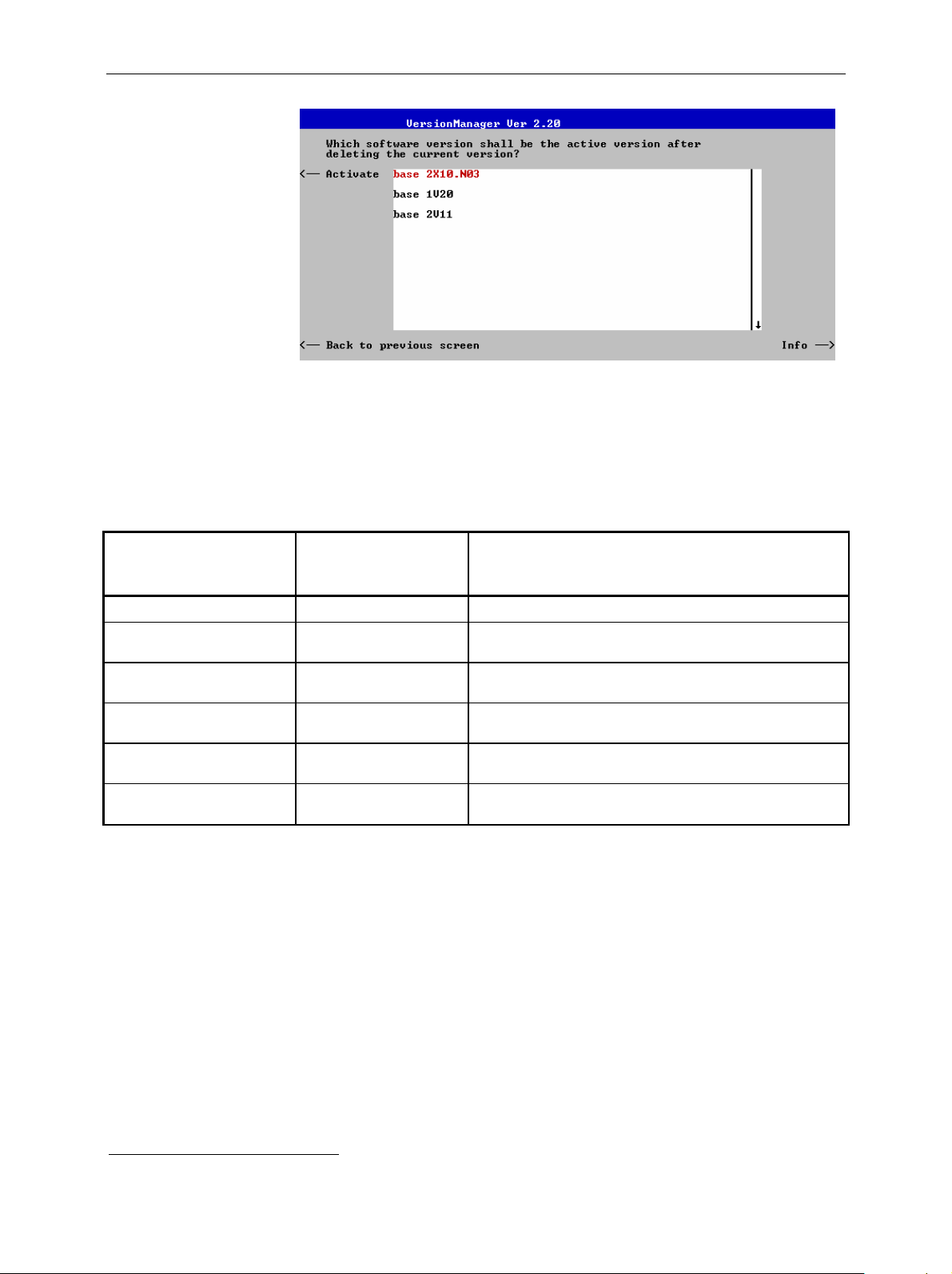
R&S CMU Software Update and Version Management
Activate Activate the current firmware configuration.
Install software...
Install software... opens a list of all fir m ware installation versions available on
an external storage medium (floppy disk/PCMCIA card). As explained in
Table 1-3, this function depends on the type and number of storage media
and on the number of installation versions available.
Table 1-3 Software installation with the VersionManager
Storage medium with FW
installation version
Floppy 1
several
PCMCIA card
in slot 0 or 1 (right or left s i de)
several
PCMCIA card
in slot 0 and in slot 1
several
2
Number of FW
installation versions
1
1 (per PC-card)
VersionManager function
Install software version <version> from floppy
Install softw are from floppy
–> Open software version selection dial og (see below).
Install software version <version> from PC-card slot <slot_no>
Install software from PC-card slot <slot_no>
–> Open software version selection dial og (see below).
Install softw are version <version> from PC-card
–> Open PC-card selection dialog (s ee bel ow).
Install software from PC-card
–> Open PC-card selection dialog (s ee bel ow).
PC-card
selection dialog:
The PC-card selection dialog selects either PCMCIA card slot 0 (r ight side)
or slot 1 (left side) for installation.
2
Media without FW installation versions are ignored.
1100.4984.12 1.29 E-12

Software Update and Version Management R&S CMU
Install software... Select the card in slot 0 or slot 1 as an installation
medium. If the medium contains several installation
versions, the software version selection dialog is called up,
see below.
Software version
selection dialog:
Upgrade options: In contrast to the Activate software dialog, the software selection dialog
The software version selection dialog lists all installation versions on the
current medium (floppy, PCMCIA card). The dialog can be operated as
explained above; see Activate software.
Install Install the current firmware version.
handles base software versions and network options separately. As a
consequence, differ ent versions of the base sof tware can be combined with
different options to create new firmware configurations. For example, it is
possible to update the base software without affecting the associated
network options or vice versa. Moreover, the same base software version
can be installed several tim es and combined with different network options
(and vice versa), so it m ay enter into several firmware configurations. The
following simple rules apply:
• W ith a new version of a network option, it is only possible to update one
of the existing configurations. The following selection dialog is
automatically skipped.
• With a new base software version, it is possible to either update an
existing configuration or create a new one. A dialog selecting between the
two alternatives is opened:
1100.4984.12 1.30 E-12

R&S CMU Software Update and Version Management
Note: This dialog is skipped if the new base software
version is not compatible with any of the existing
configurations. An incompatible new base software
must be installed as a new base software.
Install as new base Create a new configuration based on the base
software to be installed. The upgrade s election dialog
described below is sk ipped. Network options can be
assigned to this base software in a second stage of
the installation.
Upgrade existing v. Select an exis ting configuration and replace the base
software of this version. To this end, the upgrade
selection dialog described below is opened.
Force verm update If the option is checked the cur rent VersionManager is
overwritten every time that a new base system is
installed, even if this means a downgrade of the
VersionManager version. This feature is pr imarily for
service purposes.
After selection of an upgrade software version compatible with one of the
configurations stored on the hard disk , the upgrade selection dialog is called
up:
Upgrade Replace the bas e software vers ion or network option selec ted
in the software version selection dialog.
Alternatively, if none of the configurations stored on the hard disk is
compatible with the software version selected, an error message is
displayed. E.g., for an incompatible Bluetooth version:
1100.4984.12 1.31 E-12

Software Update and Version Management R&S CMU
Terminating the
software update:
Back to... Close the current sc reen and go back to the software v ersion
selection dialog to select a compatible software version.
After successf ul installation of each software version the CMU displays the
following screen:
Install next software... Go back to the software version selection dialog to
select additional software modules to be installed in
the same VersionManager session. This function
depends on the storage media and the number of
software installation versions available; s ee Table 1-3
on page 1.29.
Change disks Update the current screen after a change of the
storage medium.
Finish installation Close the VersionManager and reboot the CMU
(remove the external disk from the disk drive). The
installed firmware c onfigurations are then operational.
The last configuration ins talled is taken as the active
configuration in the subsequent measurement
session.
Note: Notice messages after firmware updates
In most cases firmware updates don’t affect the accuracy of the
measurements. There are some exceptions where a correction procedure
must be executed in the Maintenance menu after the fir mware update. The
R&S CMU displays a notice message whenever this happens. The box
contains the name of the required correction proc edure and appears during
startup until the correction has been performed.
1100.4984.12 1.32 E-12

R&S CMU Software Update and Version Management
Lack of disk space: Before installing the next sof tware version, the CMU checks whether there is
enough disk space on the hard disk. If not, the following dialog is displayed:
List software
Firmware update after
board change(…)
Edit service tables
Delete Delete the current version and return back to the
previous screen.
List software opens a list of all available firmware configurations. It is
possible to activate and delete conf igurations fr om the list; see des cription of
Activate software and Delete software functions above.
This function depends on whether a user correction file named
USERCOR1.DAT is stored in the directory INTERNAL\USERCOR\ of the
internal hard disk.
• If no user correction file is available, Firmware update after boar d change
performs an update of the current firmware including a complete CMU
hardware detection. No external installation disk is required. The update
takes som e time and should be attempted in case of problems or after a
modification of the CMU hardware configuration only (also after a
combined hardware/software exchange).
• If a user correct ion file is found, Firmware update after board change…
opens a submenu to activate or deactivate the RF user correction; see
section Compiling and Loading User Correction Tables on p. 1.37 ff.
Edit service tables calls up the Service Table Editor menu showing all
hardware modules that are possibly fitted in your instrument. For service
purposes, further information can be obtained by typing a particular board
name and board index in the two lines below the table.
1100.4984.12 1.33 E-12

Software Update and Version Management R&S CMU
Exit
Write log files to disk
Delete non volatile
ram
Scan disk
List all versions to
disk
Copy non volatile ram
to disk
Defragment disk
Exit closes the VersionManager and resumes the CMU start-up procedure.
Write log files to disk c opies all *.log files stored on the CMU hard disk to an
external storage medium (floppy or PCMCIA card). The *.log s ource files on
the hard disk are not deleted.
The Write log files to disk f unction opens a blue mess age box indicating the
storage capacity of the external disk needed. The *.log files can be
distributed over several disks. If no disk is available, the VersionManager
displays a warning and does not start copying.
Delete non volatile ram deletes all entries stored in the non volatile ram of the
CMU. This m emory contains particular settings of the last CMU session that
can be reused in the next session (e.g. the last active function group and
measurement menu, special configuration etc.).
Deleting the non volatile ram can be useful after an abnorm al termination of
a CMU measurement session.
Note: The s ettings s tor ed in the non volatile r am c an also be wr itten to
a configuration file and reused in later sessions; see Chapter 3,
section Saving Configurations.
Scan disk closes the VersionManager, ex ecutes the MS Scan Disk program
and finally returns you to the VersionManager. Refer to your Scan Disk
documentation for further information.
Note: This function is not available while a base software version
<V3.00 is active.
List all versions to disk writes the s oftware configurations indicated via List
software to an ASCII text file that is stored on the external disk.
Copy non volatile ram to disk copies the contents of the non volatile ram to
the external disk (floppy, PCMCIA).
In this way, the settings stored in the non volatile ram can be used on
another CMU.
Defragment disk closes the VersionManager, executes the MS Defrag.exe
program and f inally returns you to the VersionManager. Defragmenting the
hard disk is suitable to improve performance after installing and deleting
many different software versions. Refer to your Defrag.exe documentation
for further information.
Note: This function is not available while a base software version
<V3.00 is active.
Info
1100.4984.12 1.34 E-12
Info opens an output window displaying information on the current screen.
Separate Info windows are provided for the different VersionManager
dialogs.

R&S CMU Software Update and Version Management
Error and notify
message
Escape Close the Info screen and return to the previous screen.
During operation, the VersionManager can display two different types of
messages:
• Error messages indicating that an action could not be successfully
performed are displayed in yellow boxes. All error messages with
possible reasons and rem edial actions are explained in Chapter 9 of this
manual.
• Notify messages describing ongoing processes of the instrument are
displayed in blue boxes. These messages are self-explanatory and do not
require an action to be taken by the user.
1100.4984.12 1.35 E-12

RF User Correction R&S CMU
RF User Correction
The purpose of the RF user c or rec tion is to com pens ate for an inevitable frequency and level-dependent
attenuation in the test setup (frequency and level response correction). Level correction values are
determined by means of a signal generator or power meter connected to the CMU’s input and output
ports and stored to a file, which is transferred to the CMU in order to modify its RF generator level and to
correct its RF analyzer results.
The correction values must be acquired independently for the input and output connectors of the
instrument.
Note: In addition to the RF user correction described here, the instrument provides a frequencydependent input and output attenuation for each function group. The fr equency-dependent attenuation is
defined in the RF
manuals for the relevant network options.
Output level
correction
tab of the Connection Control menu; ref er to Chapter 4 in this manual or in the
The correction values for output signals (connectors RF1, RF2 or RF3 OUT)
modify the RF generator level so that the actual RF signal power at the input of the
DUT is equal to the nominal RF generator level.
UNIVERSAL RADIO COMMUNICATION TESTER CM U 200
CMU
RF level: P
RF Frequency: f
Correction(P
nom
dBm
nom
f
, f) = x dB
.
FUNCTION SYSTEM
MENU
DATA
CTRL
SELECT
789
G/n
mV
abc def ghi
456
µV
W
jkl mno pqr
k/m
123
dBµV
stu vwx yz
1
F
E
#
*
*
dBm
.
0
-
symb
Ω
dB
mark
_ µ
UNIT...
ON / OFF ENTER
EXP/CMP CONT/HALT
CONTROL
CLR
AUX 1 AUX 2
INS
DEL
AF IN AF OUT
VOL
AUTO
INFO R ESET
ESCAPE
1100.0008.02
HELP SETUP
PRINT
VARIATIONDATA
A
BM/µ
C
D
DATA 1
DATA 2
AUX 3
SPEECH
(P
+ x) dBm P
RF 2 RF 1
RF4 IN
RF 3 OUT
13 dBm
2 W
13 dBm
MAX
MAX
MAX
nom
50 W
MAX
Attenuation (P
= x dB
, f)
nom
nom
dBm
x
3
2
DEF
GHI1ABC
564
8
9
ÜVW7STU
XYZ
.-0
SCRC L M
Input level
correction
The correction values for input signals (connector s RF1, RF2 or RF4 IN) modify
the measured analyzer level so that the result for the RF s ignal power is equal to
the power transmitted by the DUT.
UNIVERSAL RADIO COMMUNICATION TESTER CM U 200
CMU
RF Frequency: f
Correction(Pnom , f) = x dB
RF level (meas.): P
nom
dBm
.
FUNCTION SYSTEM
MENU
DATA
CTRL
SELECT
789
G/n
mV
abc def ghi
M/µ
456
µV
W
jkl mno pqr
k/m
123
dBµV
stu vwx yz
1
F
E
#
*
*
dBm
.
0
-
symb
Ω
mark
dB
_ µ
UNIT...
ON / OFF ENTER
EXP/CMP CONT/HALT
CONTROL
CLR
AUX 1 AUX 2
INS
DEL
AF IN AF OUT
VOL
AUTO
INFO R ESET
ESCAPE
1100.0008.02
HELP SETUP
PRINT
VARIATIONDATA
A
B
C
D
DATA 1
DATA 2
AUX 3
SPEECH
(P
- x) dBm P
RF 2 RF 1
RF4 IN
RF 3 OUT
13 dBm
2 W
50 W
13 dBm
MAX
MAX
MAX
nom
MAX
Attenuation (P
= x dB
, f)
nom
nom
dBm
x
3
2
DEF
GHI1ABC
564
8
9
ÜVW7STU
XYZ
.-0
SCRC L M
Once the correction tables have been transf err ed to the instrum ent, the RF user correction is an internal
procedure. There are several advantages of using this internal correction method rather than postprocessing the CMU results by means of an external measurement program:
3
• The input level correction affects all acquired RF power results
including derived quantities (e.g. the
results of the limit c heck) without slowing down the speed of the measurem ents. Evaluating derived
quantities by means of an external program can be tedious. The RF user correction ens ures that all
results, including the derived ones, are consistent.
• The user correction is included in all results displayed in the measurement menus.
• Correction data can be acquired individually for each instrument and stored to its internal hard disk. If
several testers are used in a produc tion measurement system, the individual units are independent
from each other and interchangeable.
3
Exception: The wideband power, which is provided in the Analyzer/Generator menu of the RF function group and in many network test applications, is always uncorrected.
1100.4984.12 1.36 E-12

R&S CMU RF User Correction
Compiling and Loading User Corr ection Tables
To generate user correction tables and activate the user correction proceed as follows:
To deactivate old user
correction (if available)…
1. Start the CMU and press the Menu Select key after the boot-up
sequence is terminated (from the moment when the CMU display
turns black until the end of the 3-beep acoustic signal) to activate the
VersionManager.
2. Select Firmware update after board change…
3. In the submenu opened, select Firmware update after boar d change
without user correction and Back to previous screen.
Settings for acquiring
correction values
The CMU closes the VersionManager and resumes the start-up
procedure.
4. Open the Data m enu and acc ess the Arrange tab. Delete or rename
the old user correction file stored in the directory
INTERNAL\USERCOR\USERCOR1.DAT.
5. Press Menu Select to close the Data menu and access the Menu
Select menu.
The following settings and precautions will ensure m ax im um acc uracy of
the user correction:
6. From the Menu Select menu, access the RF function group or one
of the network test options that will be used for the corrected
measurements.
7. In the RF
input and output attenuation factors (Ext. Att. Input, Ext. Att. Output)
that will be used for the corrected measurements.
8. In the Analyzer tab of the Connec tion Control menu, select the RF
input path attenuation (Analyzer Level – RF Attenuation: Normal,
Low Noise or Low distortion) that will be used for the corrected
measurements and set the RF Mode to Manual.
Note: The CMU provides a various mechanisms for automatic
tab of the Connection Control menu, select the external
input level control, e.g. the Analyzer Level – RF Modes Auto
(autoranging) and PCL (in GSM-MS networks). To avoid
unexpected effects, it is recommended to deactiv ate these
control mechanisms and always measure the correction
values at constant (Manual) maximum input level.
1100.4984.12 1.37 E-12

RF User Correction R&S CMU
To acquire the input
correction values…
To acquire the output
correction values…
To activate the user
correction…
9. Apply the RF output signal of an external signal generator to one of
the RF input connectors RF1, RF2, or RF4 IN of the CMU using the
test setup (cables, power splitters, antenna coupler…) that will be
used for the corrected measurements.
10. Vary the level and frequency of the signal generator and calculate
the correction values as the difference between the external
generator level and the measurement result at the CMU. If
necessary, adapt the external input attenuation (see step 7) to force
the correction values into the allowed range of
[–1.2 dB, +1.2 dB].
11. Apply the RF generator signal of the CMU to one of the RF output
connectors RF1, RF2, or RF3 OUT of the CMU and feed it to a
power meter, using the tes t setup (cables, power splitters, antenna
coupler…) that will be used for the corrected measurements.
12. Vary the level and frequency of the CMU generator signal and
calculate the correction values as the difference between the
generator level and the measurement result at the external power
meter. If necess ary, adapt the external output attenuation (see step
7) to force the correct ion values into the allowed range of
+1.2 dB].
[–1.2 dB,
13. Repeat the steps no. 9 and 11 for all input and output connectors
needed and write the acquired c orrection values into a comm on file
named USERCOR1.DAT with the format specified in section File
Format for User Correction Tables on p. 1.39 ff.
14. Tr ansfer the file to the CMU using the IEEE bus, the serial interf ace
or the PCMCIA interface and copy it to the directory
INTERNAL\USERCOR\.
15. Shutdown and re-s tart the CMU and pr es s the Menu Select key after
the boot-up sequence is terminated (from the moment when the
CMU display turns black until the end of the 3-beep acoustic signal)
to activate the VersionManager again.
16. Select Firmware update after board change…
17. In the submenu opened (see step no. 3), select Firmware update
after board change with user correction.
The CMU checks the file USERCOR1.DAT for com patibility with the file
format specification and generates a message, should an error be
detected. Afterwards, the CMU closes the VersionManager and resumes
the start-up procedure. A mes sage indicates that the user correction is
active.
Final test 18. Repeat the s teps no. 9 and 11 with active user correction to m ake
sure that the entire procedure was performed without errors.
1100.4984.12 1.38 E-12

R&S CMU RF User Correction
File Format for User Correcti on Tabl es
The user correction file is an ASCII file named USERCOR1.DAT that is stored in the directory
C:\INTERNAL\USERCOR\ on the internal hard disk of the CMU. The file contains up to 6 independent
tables to store the correction values f or the 3 RF output c onnector s and the 3 RF input connectors of the
instrument. Each table has the following structure:
[PortID]:
[Level1]: [Dev11] [Dev12]
[Level2]: [Dev21] [Dev22]
... ... ... ... ...
[Levelm]: [Devm1] [Devm2]
[Freq1] [Freq2]
Comments in the f ile must be introduced by a double dagger #. Spaces and indentations ar e allowed for
easier readability of the file. The first c harac ter in a line c an be a minus sign but must not be a plus s ign.
The following example shows a valid user correction file:
# This is a comment
# (any number of spaces is allowed)
# indentations are allowed,
# spaces and TAB are used for separation
RF2in: 500 1000 1500 2000
10: 1.20 -1.2 -.23 -0.5 # comments are allowed at the end of a line
0: 0.34 1.14 1.20 -1.2
-10: 1.19 -1.19 -1.12 1.00
-14: -0.32 +1.11 -0.50 1.10
RF1in: 200 800 1500
10: +1.20 -.91 .5
0: -0.12 +1.11 -0.50
RF3OUT: 400 1000 1555 2500
10: 1.20 -1.20 -0.23 -0.5
0: 0.34 1.14 1.20 -1.2
-10: 1.19 -1.19 -1.12 1.00
-14: -0.12 +1.11 -0.50 1.10
...
...
...
[Freqn]
[Dev1n]
[Dev2n]
[Devmn]
Note: In general RF user correction tables are no longer valid after an update of the path
correction data, e.g. by means of the automatic calibration system R&S ACS. To ensure
that outdated user correction data are not used inadvertently, the ACS renames all files
c:\internal\usercor\ *.dat
➠
c:\internal\usercor\ *.bak after a change of the path correction
data. Existing *.bak files are overwritten.
Ranges of Values and Limitations
The table contains the following elements:
PortID
Frequency points
Identifier for the RF connector, written in upper or lower case letters and
followed by a colon. The following port IDs are valid:
RF1IN, RF2IN, RF4IN for the 3 RF input connectors (input level correction)
RF1OUT, RF2OUT, RF3OUT for the 3 RF output connectors (output level correction)
Frequency of the measured or generated signal in MHz, to be arranged in
ascending order, starting in colum n 2 (lowest frequency). The frequency points
must be integer numbers (i.e. integer multiples of 1 MHz) and can be
distributed across the entire RF input and output frequency range of the
instrument (see data sheet).
1100.4984.12 1.39 E-12

RF User Correction R&S CMU
Level points
Level of the measured or generated signal in dBm, to be arranged in
descending order, starting in row 2 (highest level). The level points must be
positive or negative integer numbers, followed by a colon, and can be
distributed across the entire RF input and output power r ange of the connec tor s
(see data sheet). Negative levels must be preceded by a minus sign “-“; using a
plus sign “+” for positive numbers is not allowed.
Correction values
n times m level c orrec tion values f or the m eas ured or generated s ignal in dB (if
n is the num ber of frequenc y points, which is equal to the number of corr ection
values per table row, and m is the num ber of level points). T he total number of
correction values n times m must not exceed 120 (it is possible though to
choose m=120 and n=1 and vice versa).
The level correc tion values must be in the range between -1.20 dB and +1.20
dB. This is suff icient to com pensate f or a f requenc y response or level response
caused by the test setup. Larger, correction factors can be defined by
combining the user correction with a constant external input or output
attenuation (see section RF Connectors in Chapter 4). Two consecutive
correction values may be separated by any number of spaces or tabs.
Positive (negative) correction values for an output signal compensate for an
external attenuation (gain) and increase (decrease) the generator level. Positive
(negative) correction values f or an input signal are added to (subtracted from)
the measured RF signal levels.
Interpolation Rules
The CMU uses the values in the cor rection tables to interpolate c orrection f actors at arbitr ary frequency
and level values. The following rules apply:
• At constant frequency, the correction value associated with the level point P
range between (P
+ Pm)/2 and (P
m+1
+ Pm)/2: The ranges with constant value adjoin each other in
m–1
is valid in the level
m
the middle between two consecutive level points.
• At constant level, the correction factors are linearly interpolated between consecutive frequency
points.
1100.4984.12 1.40 E-12

R&S CMU Contents of Chapter 2
Contents
2 Getting Started .................................................................................................... 2.1
A Short Tutorial on CMU Operation................................................................................................2.1
Condensed Operating Instructions...........................................................................................2.1
How to access and close menus..............................................................................................2.2
How to use dialog elements in the menus ...............................................................................2.3
Startup of the CMU...........................................................................................................................2.4
RF Measurements.............................................................................................................................2.8
1100.4984.12 I-2.1 E-1


R&S CMU A Short Tutorial on CMU Operation
2 Getting Started
The following chapter pres ents a sam ple session with the universal r adio comm unication tes ter CMU. It
is intended to provide a quick overview of the settings provided in the base system and the RF f unction
group. No specific device under test is required. For an introduction to mobile network tests (e.g. tests of
GSM900/1800/1900 mobile phones) please refer to the relevant operating manuals.
Before starting any measurem ent with the CMU, please note the instructions given in Chapter 1 for putting the instrument into oper ation. In this c hapter and in Chapters 3 to 4 of the c om plete operating m anual you will find detailed information on custom izing the instrument and the display according to your
personal preferences.
The steps to perform are explained on the left side of each double-page together with the results obtained on the CMU screen. On the right side, additional inform ation is given. We also point out alternative settings and related measurements which could not be reported in detail.
For a systematic explanation of all menus, functions and parameters and bac kground inform ation refer
to the reference part in Chapter 4 of the operating manual.
A Short Tutorial on CMU Operation
The principles of manual operation – controls, operating menus, dialog elements and measurement
control – are discussed in Chapter 3 of the operating manual. Below we list some essentials for first
users:
Condensed Operating Instructions
1. Press the RESET key on the front panel to set the ins trum ent to the default s tate befor e you config-
ure a new measurement.
2. Press ENTER to confirm selections, even if No or Yes is displayed.
3. The MENU SELECT front panel key can be pressed in any state of the unit. A large popup menu is
then displayed in which the function group (network etc.), signalling mode, and measurement
menus can be selected. Activate by pressing ENTER.
4. A front-panel LED indicates which of the RF connectors is configured as output. In the menu, the RF
generator can be activated or deactivated with ON/OFF (green/red). The front-panel LED goes out if
the generator is in the OFF position.
5. A front-panel LED indicates which of the RF connectors is configured as input. In the menu, the
measurement c an be controlled via the ON/OFF and CONT/HALT keys (ON (green), OFF (red) and
HLT (yellow) states). In the OFF state, the LED goes out.
6. The SETUP hardkey allows to make static, measurement-independent default settings such as
Remote or Time, to check which options are installed and to activate new software options.
7. The softkeys to the right of the m enus are used to change the hotk eys across the bottom and their
functions. Pressing the Menus softkey (bottom right) allows a fast switchover between related
menus using the hotkeys.
1100.4984.12 2.1 E-1

A Short Tutorial on CMU Operation R&S CMU
How to access and close menus
A startup menu is displayed automatically when the CMU is switched
on.
SETUP
Some general configuration and s elect ion menus can be opened via the
MENU SELECT, RESET, INFO, PRINT, HELP or SETUP keys on the
front panel.
The hotkeys displayed across the bottom of a main m enu or graphical
measurement menu are used to switch over between different main
menus or graphical measurement menus. Tabs in popup menus are
also accessible via hotkeys.
ESCAPE
The Connect. Control softk ey (always at the top right) is available in all
measurement menus. This softkey opens a popup menu defining the
input and output connectors, the external attenuation, the reference
frequency as well as many network-specific settings.
In the Signalling test modes of m any network options, the Connection
Control menu is also used to set up and terminate a connection between the CMU and the DUT.
The Connec tion Control menu also c ontains the input path and the trig-
ger settings for the current function group and signalling state.
If a special configuration m enu exists for a measur ement or for a generator the corresponding softkey is marked with a yellow arrow. The
configuration menu is opened by pressing the softkey twice.
All CMU popup menus can be closed with the ESCAPE key.
Main menus and graphical m easurement menus are closed on switch-
ing to another main or graphical measurement menu.
1100.4984.12 2.2 E-1

R&S CMU A Short Tutorial on CMU Operation
How to use dialog elements in the menus
The dialog elements as signed to a softk ey are selected by pressing the
softkey.
Different input fields can be selected by means of the 4 cursor keys
(blue frame shows active input field).
One of several elements in a list or toggle switch can be selected with
the rotary knob.
For a comprehensive introduc tion to manual operation of the CMU refer to Chapter 3 of the operating
manual.
Numeric values can be either incremented/decremented using the rotary knob or entered via the numeric keypad or an external keyboard.
1100.4984.12 2.3 E-1

Startup of the CMU R&S CMU
Startup of the CMU
This section describes how to custom ize the CMU and perform simple RF m easurem ents. As a prerequisite for starting the session, the ins trument must be corr ectly set up and connected to the AC power
supply as described in Chapter 1.
o
I
Step 1
¾ Switch on the CMU using the mains
switch at the rear.
¾ Check the operating mode of the instru-
ment at the ON/STANDBY key on the
front panel. If the CMU is in standby
mode, press the ON/STANDBY key.
Step 2
The CMU is booted and after a short while
displays the startup menu. This menu is
usually closed as soon as the instrument
software is loaded and the startup test is
finished.
¾ Press the Wait hotkey to prevent the
instrument from switching to another
menu.
The Wait hotkey changes to Cont. with the
additional message Change to last menu
displayed on top.
Press the Cont. hotkey to resume the
¾
startup process.
e
f
c
d
Step 3
RESET
¾ Press the RESET key to open the Reset
popup menu.
¾ Proceed as des cribed in Chapter 4 of the
operating manual, section Reset of In-
strument Settings, to expand the tree of
function groups.
¾ Select the function groups Base and RF
to be reset (the corresponding nodes
must be black).
¾ Use the cursor keys to activate the Reset
button and press ENTER.
¾ In the popup window opened (Are you
sure?), select Yes to confirm the instru-
ment reset.
The CMU indicates that it perfor ms a partial
reset of the two selected function groups and
is then ready to carry out the following steps.
The Reset popup menu is closed automatically.
1100.4984.12 2.4 E-1

R&S CMU Startup of the CMU
Additional Information... Alternative Settings
and Measurements
... on Step 1
c Mains switch on the rear panel
When the mains switch at the rear is set to the O position, the
complete instrum ent is disconnected from the power supply.
When the m ains power switch is set to the I position, the instrument is in standby mode or in operation, depending on the
position of the ON/STANDBY key on the front panel.
d ON/STANDBY key on the front panel
The ON/STANDBY key at the front of the instrument determines whether the instrum ent is in standby mode or in operation.
Standby mode:
Only the OCXO refer ence frequency oscillator (option CMUB11/B12), if installed, is supplied with operating voltage. The
orange LED (STANDBY) is illuminated.
) Chapter 1
The CMU is automatically set to
the AC supply voltage and frequency applied. Note the permissible ranges of AC voltages and
frequencies indicated at the rear
of the instrument and in the data
sheet.
) Chapter 1
The behavior of the CMU when it
is switched off depends on the
Front Module controller type installed.
Operation:
The green LED (ON) is illuminated and all modules of the instrument are supplied with operating voltage.
... on Step 2
e Startup menu
The startup menu displays the following information:
• The startup procedure (Process)
• Instrument model, serial number and version of the CMU
base software (Info).
• Installed hardware and software options and equipment
(Options). Available software options are listed with their
version numbers.
• Progress of the startup procedure (Startup bar graph).
f Wait hotkey
By default the CMU switches to the last main menu of the
previous session after term inating the s tartup proc ess. This is
convenient if an interrupted session is to be r esum ed or if the
instrument is generally used in a definite operating mode.
On the other hand, the Wait f unction can be used to access
the configuration menus which can be opened by means of
the front panel keys before the actual measurement is
started.
While the Wait hotkey is active, a reset of the instrument is
not possible.
) Chapter 4 of the operating
manual
The Default hotkey can be used
to load the factory default settings
for all function groups. Settings
made and stored in the previous
session are overwritten.
The CMU’s user interface has
been optimized with the aim of
facilitating fast and easy switchover between the menus and
measurement modes. This includes the general configurations
which can be accessed fr om any
measurement menu.
The most im portant selection and
configuration menus s uch as Re-
set, Setup, Menu Select etc.are
directly accessible via front panel
keys.
1100.4984.12 2.5 E-1

Startup of the CMU R&S CMU
SETUP
Step 4
¾ Press the SETUP k ey to access general
device settings.
¾ Press the Time hotkey to switch over to
the Time tab of the Setup menu.
Step 5
The Time tab of the Setup menu displays the
current time zone, time and date.
¾ Use the rotary knob to move the focus
onto the Time section of the Setup table.
If necessary, press the rotary knob or the
ON/OFF key to expand the parameters in
the table (see Chapter 3 of the operating
manual).
c
d
¾ Move to one of the input f ields as s ociated
to the Time parameter, select with
ENTER and use the rotary knob or the
numeric keypad to correct the settings for
the current time. Hours, minutes and
seconds can be edited separately.
¾ Press ENTER to confirm the entries and
quit the input fields.
¾ Move to Zone select field, activate with
ENTER, and use the rotary knob to
choose your own time zone.
In the same way, activate the Format
¾
select field and use the rotary knob to
switch over between European and North
American time conventions.
1100.4984.12 2.6 E-1

R&S CMU Startup of the CMU
Additional Information... Alternative Settings
and Measurements
... on Step 4
c Softkeys and hotkeys
Softkeys and hotkeys are activated by pressing the associated keys on both sides and across the bottom of the display.
The general purpose of sof tk eys is to provide settings, control
the generator and the measurements. Hotkeys are used to
switch over between different menus and different tabs belonging to a popup menu.
Chapter 3 of the operating
)
manual
... on Step 5
d Setup menu
The Setup m enu com pris es sever al tabs pr oviding general instrument settings . It is advisable to check and adjust the factory settings when you operate the CMU for the first time.
To switch over between the tabs of the setup menu use the
hotkeys displayed at the bottom of the display.
) Chapter 4 of the operating
manual
The different types of m enus and
control elements of the graphical
user interface is explained in
Chapter 3 of the operating manual. In the same chapter you can
find a short tutorial on the entry of
numbers and characters.
1100.4984.12 2.7 E-1

RF Measurements R&S CMU
RF Measurements
In the RF function group, a continuous or pulsed RF s ignal can be generated and a RF signal with definite frequency characteristics can be analyzed. The signal level can be plotted in oscillographical
(Power) or spectral (Spectrum) representation.
MENU
SELECT
Step 1
¾ Press the Menu Select key to open the
Menu Select menu.
¾ Use the cursor keys and the rotary knob
to select the RF function group in the
left half of the Selection table.
¾ In the right half of the table, select the
Analyzer/Generator menu.
¾ Press the Enter key to activate the
measurement selected and open the
RF Analyzer/Generator menu.
c
Step 2
In the Settings table the Ana-
lyzer/Generator menu indicates the pa-
rameters of the signal gener ated and those
of the signal received and analyzed.
At present, all param eters have been reset
to factory default values. Different softkey/hotkey combinations and popup menus
are provided to change the settings. Us erdefined parameters will be saved for later
sessions when the CMU is switched off.
The Power output field in the Ana-
lyzer/Generator menu shows an invalid
result ("---") because at present no RF
input signal is applied to the CMU.
d
1100.4984.12 2.8 E-1

R&S CMU RF Measurements
Additional Information... Alternative Settings
and Measurements
... on Step 1
c Menu Select menu
The Menu Select menu shows all function groups installed on
your CMU. If a function group is selected the available test
modes and measurement menus are indicated. Function
groups representing digital network tests (such as
GSM400/850/900/1800/1900-MS) are generally subdivided in
the two test modes Non Signalling and Signalling, each containing a number of measurement menus.
The RF function group is available on any CMU regardless of
the software options purchased. It com prises the three measurement menus Analyzer/Generator, Power and Spectrum.
All three measurement menus are directly accessible from
the Menu Select menu.
... on Step 2
d Analyzer/Generator menu
The Analyzer/Generator menu contains several softkeys to
• Control the RF signals received and analyzed (Analyzer
Level, Analyzer Settings)
• Control the RF signals generated (Generator)
Defining a level and frequency via the Generator softk ey and
the associated hotkeys implies that a continuous signal ( CW )
with this level and frequency is generated.
The RF Max. Level defined via Analyzer Level, however, denotes the maximum input power which can be measured.
This is identical with the upper edge of the Power diagram
(see below). The permiss ible range of Max. Level depends on
the input connector and external attenuation us ed (see section Analyzer Settings in Chapter 4).
) Chapter 4 of the operating
manual
For digital network tests refer to
the relevant operating manuals.
e.g. GSM400/850/900/1800/1900-
MS.
Chapter 4 of the operating
)
manual
The Generator softkey provides
the most important s ettings of the
Generator tab of the Connection
Control menu.
The Analyzer Level and Analyzer
Settings softkeys correspond to
the Analyzer tab of the Connection Control menu.
Defining a (center) Analyzer Settings – Frequency implies
that only signals around this frequency are analyzed.
The Analyzer Settings – RBW hotkey defines the resolution
bandwidth of the analyzer.
e The status of the Analy zer Power measur ement is shown in
the corresponding softkey. For ongoing measurements, the
result in the Power output field is constantly updated.
At present no input signal is available so that the Power output field shows an invalid result “– – –“
Once the softk ey is selected, the Analyzer Power measurement can be switched off and on by means of the ON/OFF
key. In contrast, the CONT/HALT toggle key halts the measurement after the next valid result has been obtained.
1100.4984.12 2.9 E-1
Ch. 4 and Ch. 5
)
The options for the m easurement
status are ON, OFF, or HLT. The
HLT state is reached after the end
of a single shot measurement
(see the section about measurement control in Chapter 5 of the
operating manual).
 Loading...