

Page 1

Quick Start Guide
Universal
Radio Communication Tester
R&SCMU 200
1100.0008.02/10/30/53
Printed in Germany
1100.4961.62
-04
Test and Measurement Division
Page 2

The firmware of the instrument makes use of several valuable open source software packages. The
most important of them are listed below together with their corresponding open source license. The
verbatim license texts are provided in on the user documentation CD-ROM (included in delivery).
Package Link License
STLPort http://www.stlport.org/ STLPort License
InfoZIP http://www.info-zip.org Copyright InfoZIP
UNTGZ http://www.t-st.org/untgz_f.htm GNU GPL v. 2 / R&S Copyright
MD5 http://www.rsa.com Copyright RSA Data Security
Axis2 http://ws.apache.org/axis2/ Apache License v. 2.0
Jetty Server http://www.mortbay.org/ Apache License v. 2.0
Xerces http://xerces.apache.org/xerces2-j/ Apache License v. 2.0
This product includes UNTGZ for DOS (http://www.t-st.org/untgz_f.htm), and includes as the GPL'ed
source code for this program
Rohde & Schwarz would like to thank the open source community for their valuable contribution to
embedded computing.
R&S® is a registered trademark of Rohde & Schwarz GmbH & Co. KG.
Trade names are trademarks of the owner
Page 3
R&S CMU Documentation Map
Quick Start Guide
The present quick start guide describes everything that is needed
to put the instrument into operation and helps you to get familiar
with the radio communication tester. In particular, the quick start
guide describes the safety-related aspects to be observed when
setting up or operating the instrument. The guide contains:
• The product brochure and specifications
• Safety instructions
• Certificates
• Customer support information, Rohde & Schwarz addresses
• Chapter 1: Preparation for Use
• Chapter 2: Getting Started
• Index for chapter 1 and chapter 2
Documentation CD-ROM
The CD-ROM provides the complete user documentation for the
radio communication testers R&S CMU 200 and R&S CMU 300:
• Printable versions of the complete operating manual
(including the contents of this quick start guide) and the
service manual
• Printable versions of the manuals for R&S CMU network test
options (see order list on the following page) and accessories
• Help systems corresponding to the contents of the quick start
guide and to the complete operating manual
• The product brochure and specifications in printable form.
• Application notes and articles
• Links to different useful sites in the R&S internet.
Optional Documentation
1100.4961.62
The complete operating manual for the radio communication
testers R&S CMU 200 and R&S CMU 300 and the manuals for
the network test options provide the complete reference
information for operation and programming. The service manual
instrument contains the performance test and other servicerelated information.
Printed versions of the manuals can be ordered as options; see
ordering information on the next page.
Note: The CD-ROM delivered with the instrument contains
printable (.pdf) versions of all these manuals.
1 E-3
Page 4

R&S CMU Models
This manual describes the following models of the Universal Radio Communication Tester R&S
CMU 200:
• Universal Radio Communication Tester R&S CMU 200, stock no. 1100.0008.02, for all mobile
station and user equipment tests including Bluetooth™ device tests.
• Universal Radio Communication Tester R&S CMU 200, stock no. 1100.0008.53, only for
Bluetooth™ device tests.
• High End Service Tester R&S CMU 200v10, stock no. 1100.0008.10. For an introduction to the
features of this model refer to the enclosed product brochure.
• Non Signalling Tester R&S CMU 200v30, stock no. 1100.0008.30. For an introduction to the
features of this model refer to the enclosed R&S CMU 200 product brochure.
The Universal Radio Communication Tester R&S CMU 300, stock no. 1100.0008.03, is described in
a separate quick start guide, stock no.
1100.4978.62
.
1100.4961.62
2 E-3
Page 5

List of Printed Manuals
The following operating manuals are related to the Universal Radio Communication Tester R&S
CMU 200 and to network test options for the R&S CMU 200. Printed manuals can be ordered from
Rohde & Schwarz using the order numbers listed below.
For Options
Manual Order Number Type, R&S… Description Stock No.
Operating Manual
CMU 200/300
Service Manual Inst.
CMU 200/300
Operating Manual
CMU-K20/-K21/K22/-K23/-K24/-K26
Operating Manual
CMU-K27/-K28
1100.4984.12
CMU 200
CMU 300
CMU-B41
CMU-B95/96
CMU-B17
CMU-K48
CMU-K14
1100.4903.82
CMU 200
CMU 300
1115.6088.12 CMU-K20
CMU-K21
CMU-K22
CMU-K23
CMU-K24
CMU-K26
CMU-K42
CMU-K43
CMU-K44
CMU-K45
CMU-K47
1115.6688.12 CMU-K27
CMU-K28
Univ. Radio Communication Tester
for mobile stations / UE
for base stations
Audio Generator and Analyzer
Additional RF Generator
I/Q and IF Interface
I/Q vs. Slot Measurement
FM Stereo Transmitter
Univ. Radio Communication Tester
for mobile stations / UE
for base stations
GSM400-MS for CMU-B21
GSM900-MS for CMU-B21
GSM1800-MS for CMU-B21
GSM1900-MS for CMU-B21
GSM850-MS for CMU-B21
GSM GT800 for CMU-B21
GPRS software extension for GSM
EGPRS software extension for GSM
Dual Transfer Mode
AMR GSM for CMU200
R&S Smart Alignment @ GSM-MS
TDMA800-MS for CMU-B21
TDMA1900-MS for CMU-B21
1100.0008.02/53
1100.0008.10/30
1100.0008.03
1100.5300.02
1159.0504.02
1159.1600.02
1157.5309.02
1200.7503.02
1100.0008.02/53
1100.0008.10/30
1100.0008.03
1115.5900.02
1115.6007.02
1115.6107.02
1115.6207.02
1115.6307.02
1115.6507.02
1115.4691.02
1115.6907.02
1157.4277.02
1150.3100.02
1157.4477.02
1115.6607.02
1115.6707.02
Operating Manual
CMU-K29
Operating Manual
CMU-K53
1100.4961.62
1115.6888.12 CMU-K29 AMPS-MS for CMU-B21 1115.6807.02
1115.5081.12 CMU-K53 Bluetooth for CMU 1115.5000.02
3 E-3
Page 6

Manual Order Number Type, R&S… Description Stock No.
For Options
Operating Manual
CMU-K61…-K69
Operating Manual
CMU-K81/-K82
Operating Manual
CMU-K83/-K84/
-K85/-K86
1115.4962.12 CMU-K65
CMU-K66
CMU-K67
CMU-K68
CMU-K69
CMU-K61
CMU-K62
CMU-K63
CMU-K57
CMU-K58
CMU-K59
CMU-K16
CMU-K17
CMU-K15
CMU-K64
CMU-K60
CMU-K56
CMU-K96
CMU-K46
CMU-K47
1115.5581.12 CMU-K81
CMU-K82
1150.0382.12 CMU-K83
CMU-K84
CMU-K85
CMU-K86
CMU-K87
CMU-K47
WCDMA UE TX Test (3GPP/FDD)
WCDMA UE DL Generator
WCDMA UE Band III Signalling
WCDMA UE Band I Signalling
WCDMA UE Band II Signalling
WCDMA UE Band IV Signalling
WCDMA UE Band V Signalling
WCDMA UE Band VI Signalling
WCDMA UE Band VII Signalling
WCDMA UE Band VIII Signalling
WCDMA UE Band IX Signalling
WCDMA UE Band X Signalling
WCDMA UE Band XI Signalling
WCDMA UE Band S Signalling
HSDPA 3.6 Mbps
HSDPA 10 Mbps
HSUPA 5.76 Mbps
WCDMA Application Testing
Wideband AMR Codec
Smart Alignment @ WCDMA UE
CDMA800-MS (IS95) for CMU-B81
CDMA1900-MS (IS95) for CMU-B81
CDMA2000-MS (450 MHz band)
CDMA2000-MS (cellular band)
CDMA2000-MS (PCS band)
CDMA2000-MS (IMT-2000 band)
CDMA2000 Data Testing
Smart Alignment @ CDMA2000
1115.4891.02
1115.5100.02
1150.3000.02
1115.5300.02
1115.5400.02
1157.3670.02
1157.3770.02
1157.3870.02
1150.3000.02
1115.5300.02
1115.5400.02
1200.9158.02
1200.9106.02
1200.9258.02
1157.3970.02
1200.8200.02
1200.7803.02
1157.4177.02
1200.8800.02
1157.4477.02
1115.5500.02
1115.5600.02
1150.3500.02
1150.3600.02
1150.3700.02
1150.3800.02
1150.4007.02
1157.4477.02
Operating Manual
CMU-K88
1150.3998.12
1200.8300.02
1200.8400.02
1200.8500.02
1200.8600.02
CMU-K88
CMU-K839
CMU-K849
CMU-K859
CMU-K869
1xEV-DO for CMU-B88
1xEV-DO 450MHz
1xEV-DO cellular band
1xEV-DO PCS band
1xEV-DO IMT-2000 band
1150.3900.02
1200.8300.02
1200.8400.02
1200.8500.02
1200.8600.02
1100.4961.62
4 E-3
Page 7

CustomerInformationRegardingProductDisposal
TheGermanElectricalandElectronicEquipment(ElektroG)Actisanimplementationofthe
followingECdirectives:
· 2002/96/EConwasteelectricalandelectronicequipment(WEEE)and
· 2002/95/EContherestrictionoftheuseofcertainhazardoussubstancesin
electricalandelectronicequipment(RoHS).
ProductlabelinginaccordancewithEN50419
Oncethelifetimeofaproducthasended,thisproductmustnotbedisposedofinthe
standarddomesticrefuse.Evendisposalviathemunicipalcollectionpointsforwaste
electricalandelectronicequipment isnotpermitted.
Rohde&SchwarzGmbH&Co.KGhasdevelopedadisposalconceptforthe
environmentalfriendlydisposalorrecyclingofwastematerialandfullyassumesits
obligationasaproducertotakebackanddisposeofelectricalandelectronicwastein
accordancewiththeElektroGAct.
Pleasecontactyourlocalservicerepresentativetodisposeoftheproduct.
Page 8

Page 9

Certificate No.: 99035, page 1
This is to certify that:
EC Certificate of Conformity
Equipment type
Stock No. Designation
CMU200 1100.0008.02/.10/.30/.53 Universal Radio Communication Tester
CMU300 1100.0008.03
complies with the provisions of the Directive of the Council of the European Union on the
approximation of the laws of the Member States
- relating to electrical equipment for use within defined voltage limits
(73/23/EEC revised by 93/68/EEC)
- relating to electromagnetic compatibility
(89/336/EEC revised by 91/263/EEC, 92/31/EEC, 93/68/EEC)
Conformity is proven by compliance with the following standards:
EN61010-1 : 2001-12
EN61326-1 : 1997 + A1 : 1998
For the assessment of electromagnetic compatibility, the limits of radio interference for Class
B equipment as well as the immunity to interference for operation in industry have been used
as a basis.
Affixing the EC conformity mark as from 1999
ROHDE & SCHWARZ GmbH & Co. KG
Mühldorfstr. 15, D-81671 München
Munich, 2006-02-06 Central Quality Management FS-QZ / Radde
1100.0008.02-s1- CE E-12
Page 10

Certificate No.: 99035, page 2
This is to certify that:
EC Certificate of Conformity
Equipment type
Stock No. Designation
CMU-B11 1100.5000.02 Reference Oscillator
CMU-B12 1100.5100.02 Reference Oscillator
CMU-B15 1100.6006.02 Additional RF und IF Connections
CMU-B17 1100.6906.02 IQ and IF Interfaces
CMU-B21 1100.5200.02/.14/.54 Versatile Signalling Unit
CMU-B41 1100.5300.02 Audio Generator and Analyzer
CMU-B52 1100.5400.02/.14 Spreech Codec for Versatile Signalling Unit
CMU-B53 1100.5700.02/.14 Bluetooth Extension
CMU-B54 1150.2604.14 Sig. Module
CMU-B56 1150.1850.14 3GPP Signalling Unit
CMU-B66 1149.9509.02 Versatile Base Band Board
CMU-B68 1149.9809.02 Layer1 Board
CMU-B71 1100.6406.02 ABIS Interface Unit
CMU-B73 1150.2004.02 Analog Telephon Line Interface
CMU-B76 1150.0601.02 Layer1 Board for WCDMA
CMU-B78 1159.1800.02 Layer1 Board for WCDMA
complies with the provisions of the Directive of the Council of the European Union on the
approximation of the laws of the Member States
- relating to electrical equipment for use within defined voltage limits
(73/23/EEC revised by 93/68/EEC)
- relating to electromagnetic compatibility
(89/336/EEC revised by 91/263/EEC, 92/31/EEC, 93/68/EEC)
Conformity is proven by compliance with the following standards:
EN61010-1 : 2001-12
EN61326-1 : 1997 + A1 : 1998
For the assessment of electromagnetic compatibility, the limits of radio interference for Class
B equipment as well as the immunity to interference for operation in industry have been used
as a basis.
Affixing the EC conformity mark as from 1999
ROHDE & SCHWARZ GmbH & Co. KG
Mühldorfstr. 15, D-81671 München
Munich, 2006-02-06 Central Quality Management FS-QZ / Radde
1100.0008.02-s2- CE E-18
Page 11

Certificate No.: 99035, page 3
EC Certificate of Conformity
This is to certify that:
Equipment type
Stock No. Designation
CMU-B81 1100.6506.02 CDMA(IS95) Signalling Unit
CMU-B82 1150.0201.02/.04 ACCESS Board für CDMA Signalling Unit
CMU-B83 1150.0301.02/.04/.12/.14 CDMA2000 Signalling Unit
CMU-B85 1100.7002.02/.04/.12 Speech Codec for CDMA2000
CMU-B87 1150.2404.02/.04 Message Monitor for CDMA2000
CMU-B88 1158.9908.02 1xEV-DO Extension
CMU-B95 1159.0504.02 Additional RF Generator
CMU-B96 1159.1600.02 Additional RF Generator
CMU-B99 1150.1250.02 RF1 Level Range identical to RF2
CMU-U61 1100.5500.02 Floppy Disk Drive
CMU-Z1 1100.7490.02 Memory Card
complies with the provisions of the Directive of the Council of the European Union on the
approximation of the laws of the Member States
- relating to electrical equipment for use within defined voltage limits
(73/23/EEC revised by 93/68/EEC)
- relating to electromagnetic compatibility
(89/336/EEC revised by 91/263/EEC, 92/31/EEC, 93/68/EEC)
Conformity is proven by compliance with the following standards:
EN61010-1 : 2001-12
EN61326-1 : 1997 + A1 : 1998
For the assessment of electromagnetic compatibility, the limits of radio interference for Class
B equipment as well as the immunity to interference for operation in industry have been used
as a basis.
Affixing the EC conformity mark as from 1999
ROHDE & SCHWARZ GmbH & Co. KG
Mühldorfstr. 15, D-81671 München
Munich, 2006-02-06 Central Quality Management FS-QZ / Radde
1100.0008.02-s3- CE E-5
Page 12

Page 13

R&S CMU 200 Contents of Chapter 1
Contents
1 Preparing the R&S CMU for Use ........................................................................ 1.1
Front and Rear View.........................................................................................................................1.1
Rear View ..........................................................................................................................................1.7
Putting the Instrument into Operation .........................................................................................1.10
Unpacking the Instrument ......................................................................................................1.10
Setting up the Instrument .......................................................................................................1.10
Bench Top Operation...................................................................................................1.10
Mounting in a Rack.................................................................................................................1.11
Connecting the Instrument to the AC Supply .........................................................................1.12
Switching on the Instrument / Startup Test ............................................................................1.12
Switching off the Instrument ...................................................................................................1.13
How to Ensure EMC...............................................................................................................1.14
Input Level..............................................................................................................................1.14
Connecting the CMU to the Test Setup........................................................................................1.15
Connecting a Controller..........................................................................................................1.15
Connecting an External Keyboard..........................................................................................1.17
Connecting a Monitor .............................................................................................................1.17
Connecting a Printer...............................................................................................................1.18
Synchronization with External Devices; Connection of Further Components ........................1.18
Software Update and Version Management ................................................................................1.19
R&S Remote Service Tool .....................................................................................................1.19
Remote Control of the R&S CMU ................................................................................1.26
File Versions.new.........................................................................................................1.27
CMU VersionManager............................................................................................................1.29
1100.4961.62 I-1.1 E-3
Page 14

Page 15

R&S CMU 200 Front and Rear View
1 Preparing the R&S CMU for Use
This chapter describes the controls and connectors of the Universal Radio Communication Tester CMU
and gives all information that is necessary to put the instrument into operation and connect external
devices. Notes on reinstallation of the CMU software and a description of the VersionManager appear at
the end of this chapter.
Caution!
Please observe the instructions of the following sections so that you cannot cause
damage to the instrument or endanger people. This is of particular importance when
you use the instrument for the first time. Also observe the general safety instructions
at the beginning of this manual.
A more detailed description of the hardware connectors and interfaces can be found in chapter 8 of the
complete operating manual. Chapter 2 of the operating manual provides an introduction to the operation
of the CMU by means of typical examples of configuration and measurement; for a description of the
operating concept refer to Chapter 3.
For remote control of the CMU refer to the general description of the SCPI commands, the instrument
model, the status reporting system, and measurement control in Chapter 5 of the operating manual.
Front and Rear View
The front panel of the CMU consists of the VGA display with the softkey area (left side) and the hardkey
area (right side, see Fig. 1-1). Brief explanations on the controls and connectors of the hardkey area and
the rear panel are to be found on the next pages. Operation by means of softkeys is described in Chapter 3 of the operating manual, Manual Operation.
9 softkeys with
alternating function
ON/Standby key (p.4)
LC display with
menu example
UNIVERSAL RADIO COMMUNICATION TESTER CMU 200
9 softkeys with
alternating function
Escape key (p.4)
.
ESCAPE
FUNCTION SYSTEM
MENU
DATA
DATA
89
ghi
def
56
pqr
yz
vwx
E
#
*
.
-
symb
mark
ENTER
CONT/HALT
DEL
AUTO
RESET
CTRL
G/n
mV
M/7
7V
W
k/m
dB7V
F
*
dBm
dB
UNIT...
AUX 1 AUX 2
AF IN AF OUT
SELECT
7
abc
4
jkl mno
123
stu
0
_ 7
ON / OFF
EXP/CMP
CONTROL
CLR
INS
VOL
INFO
Keys and connectors
PRINT
HEL P SETUP
VARIATION
A
B
C
D1
RF4 IN
13 dBm
1100.0008.02
DATA 1
DATA 2
AUX 3
SPEECH
RF 2 RF 1
RF 3 OUT
2W
13 dBm
MAX
MAX
50 W
MAX
MAX
Bar with 8 hotkeys
Fig. 1-1 CMU front view
1100.4961.62 1.1 E-3
Page 16

Front and Rear View R&S CMU 200
Data input
Selection of the most important
CMU functions via menus
Loudspeaker, for
future extensions
PCMCIA interface
as an alternative:
Floppy disk drive
(option CMU-U61)
Fig. 1-2 CMU front view – hardkeys
FUNCTION Operating manual
Preselection of the menus:
MENU SELECT Menu selection
DATA File manager
CTRL For GSMxxx-MS Signalling tests:
Measurement Wizard
Chap. 3
Chap. 4
DATA Operating manual
Data input:
0 ... 9 Numerical input (letters for string editors)
* . E Special characters, dec. point, hex value "E"
# - F Spec. characters, sign change, hex value "F"
G/n mV A Factor 109/10-9, unit, hex value "A"
M/
µ µ
V W Factor 106/10-6, unit, hex value "B"
k/m dB µV Factor 103/10-3, unit, hex value "C"
*1 dBm dB Factor 100, unit, hex value "D"
ON / OFF Switching on/off editors/measurements
EXP/COMP
ENTER Confirmation of entry in editors
CONT/HALT Calling/quitting editors,
measurement control
UNIT
For future extensions
Chap. 3
1100.4961.62 1.2 E-3
Page 17

R&S CMU 200 Front and Rear View
System control Variation of numeric values and
group selection in popup menus
Fig. 1-3 CMU front view – hardkeys
SYSTEM Operating manual
System control:
HELP Displays online help
SETUP Instrument settings
PRINT Initialize printing of a screenshot
Chap. 3
VARIATION Operating manual
Value variation and group selection:
Rotary knob Value variation in input fields and
parameters, line selection in tables, field
selection in popup menus. Press to
expand/compress tables and pull-down
lists and to confirm entries and
selections.
Cursor key Group selection in popup menus
vertical (vertical)
Cursor key Group selection in popup menus
horizontal (horizontal),
Cursor positioning in editors and
tables
Chap. 3
1100.4961.62 1.3 E-3
Page 18

Front and Rear View R&S CMU 200
Extended editor
and instrument
control functions
Fig. 1-4 CMU front view – hardkeys
CONTROL Operating manual
Extended control functions:
CLR Clears the complete editor string
(back space)
INS Changes between insertion and overwriting
in the editor
DEL Deletes the character marked by the
cursor
VOL For future extensions
AUTO For future extensions
INFO System info and hardware diagnosis
RESET Resets to default values
Deletes the character to the left of the cursor
Chap. 3
Further Keys Operating manual
ESCAPE
ESCAPE Quits popup menus, closes an editor
discarding the entries made
ON/STANDBY Switches between operation (green LED)
and standby (orange LED)
Chap. 3
1100.4961.62 1.4 E-3
Page 19

R&S CMU 200 Front and Rear View
For future extensions
Auxiliary input/output
AUX3
Signals from/to
speech codec
(option CMU-B52)
AF inputs and outputs
Fig. 1-5 CMU front view connectors
DATA1, DATA2 Operating manual
For future extensions
Chapter 8, "Hard-
ware connectors"
AUX 3 and SPEECH Operating manual
AUX 3
SPEECH
Input and output for status, control, and trigger signals:
CMU 300: External trigger signal for
wired synchronization
Signals from/to speech codec (option CMU-B52)
Chapter 8, "Hard-
ware connectors "
Chapter 8, "Hard-
ware connectors"
AF connectors Operating manual
Connectors for audio signals:
AUX1/2 Additional input/output for audio signals
that may be used in remote control (secondary audio analyzer)
AF IN/OUT Standard input/output for the (primary)
audio analyzer
Caution: Note the maximum permissible input levels for all
AF connectors according to the data sheet in order to prevent damage to the instrument!
Chapter 4, "Audio
Generator and
Analyzer";
Chapter 8, "Hard-
ware connectors"
1100.4961.62 1.5 E-3
Page 20

Front and Rear View R&S CMU 200
Bidirectional RF connectors
RF 1 und RF 2
Sensitive RF input, high-level RF output
Fig. 1-6 CMU front view– connectors
RF connectors Operating manual
Bidirectional RF connectors for various power ranges according to the data sheet.
The two LEDs above the connectors are illuminated as long
as the CMU sends signals
Connector with high output level and connector for sensitive
RF measurements (antennas). Power ranges according to the
data sheet. Maximum permissible input and output level according to the label on the front panel.
The two LEDs above the connectors are illuminated as long
as the CMU sends signals
Caution:
Note the maximum permissible input levels for all RF connectors according to the label on the front panel or the data sheet
in order to prevent damage to the instrument!
RF connectors may warm up very much when high RF power
is fed in!
or is ready for reception .
or is ready for reception .
Chapter 8,
"Hardware
connectors "
Chapter 8,
"Hardware
connectors"
1100.4961.62 1.6 E-3
Page 21

R&S CMU 200 Rear View
Rear View
Synchronization inputs and outputs, IF interface (with option CMU-B17)
Interfaces for remote control
Signal inputs and outputs
and peripheral equipment
Fig. 1-7 CMU rear view
Mains switch Operating manual
Mains connector with switch
Mains power switch
Mains connector
Chapter 1, "Switching on the Instrument,
Startup test"
Chapter 1, "Connecting the instrument to the
AC supply”
Interfaces Operating manual
GPIB-bus connector
(IEEE 488 / IEC 625),
Parallel interface: 25-contact
printer connector, Centronicscompatible
Connector for serial interface 1: 9contact Sub-D connector
Connector for serial interface 2: 9contact Sub-D connector
Connector for an external VGA
monitor: 15-contact Sub-D
connector
USB connector for external
keyboard only (not for other
pointing or storage devices)
Chapter 1, "Connecting an External Keyboard"
Chapter 8, "Hardware Interfaces "
Chapt. 1, "Connecting an Output Device"
Chapter 8, "Hardware Interfaces”
Chapter 8, "Hardware Interfaces”
Chapter 8, "Hardware Interfaces”
Chapter 1, "Connecting a Monitor"
Chapter 8, "Hardware Interfaces”
Chapter. 8, "Hardware Interfaces”
1100.4961.62 1.7 E-3
Page 22

Rear View R&S CMU 200
Inputs and outputs for reference frequency and network-specific clock frequency
Intermediate
frequency
from CMU receiver,
IF interface
Auxiliary and
service connectors,
I/Q interface
Fig. 1-8 CMU rear view – signal inputs and outputs
Intermediate frequency Operating manual
IF3 RX CH1 (BNC connector) from CMU receiver
Chapter 8,
"Hardware
Connectors"
Reference frequency Operating manual
REF IN Input for external reference frequency
REF OUT 1 Output of reference frequency of CMU:
10 MHz or the signal of input REF IN
REF OUT 2 Output for network-specific clock
frequency
Caution!
Do not use open or unshielded cables in order to comply with EMC directives!
Chapter 8,
"Hardware
Connectors
Chapter 3, "RF
Connection
Control"
AUX, SERVICE, AUX4, extensions Operating manual
Two 9-contact and one 15-contact SUB-D connectors:
AUX Auxiliary connector providing a DC
voltage to supply external equipment
such as CMU-Z6
SERVICE Service connector for RXTX board
(only for internal test purposes)
AUX4 Bidirectional input/output for digital
status, control, and trigger signal
Chapter 8,
"Hardware
Connectors
The remaining 15-contact SUB-D connectors are
reserved for future extensions.
1100.4961.62 1.8 E-3
Chapter 8,
"Hardware
Connectors
Page 23

R&S CMU 200 Rear View
IF interface
Option CMU-B82
Access Board for
CDMA Sign. Units
I/Q interface
Fig. 1-9 CMU rear view – I/Q-IF inputs and outputs
Option CMU-B87
Message Monitor for
CDMA2000
I/Q-IF Interface (with option CMU-B17) Operating manual
Four 50 BNC connectors for option CMU-B17, I/Q and
IF Interface:
IF3 RX CH1 IN RX path, IF IN
IF3 RX CH1 OUT RX path, IF OUT
IF3 TX CH1 IN TX path, IF IN
IF3 TX CH1 OUT
15-contact SUB-D connector for input and output of I/Q
signals (option CMU-B17, I/Q and IF Interface)
The SUB-D connector below IQ CH 1 is not used.
TX path, IF OUT
Chapter 4,
"Hardware
Connectors"
Chapter 8,
"Hardware
Connectors"
Chapter 8,
"Hardware
Connectors"
Optional interfaces for data applications
Digital I/Q connector for option R&S
CMU-B82, Access Board for CDMA
Signalling Units
Ethernet connector e.g. for option R&S CMU-B87,
Message Monitor for CDMA2000
An additional Ethernet connector can be fitted below,
e.g. for option R&S CMU-Z46, WCDMA Message
Analyzer and Recorder.
1100.4961.62 1.9 E-3
Installation
instructions for
options
Installation
instructions for
options
Page 24

Putting the Instrument into Operation R&S CMU 200
Putting the Instrument into Operation
This section describes the basic steps to be taken when setting up the CMU for the first time.
Caution!
Please make sure to observe the instructions of the following sections so that you
cannot cause damage to the instrument or endanger people. This is of particular
importance when you use the instrument for the first time.
Unpacking the Instrument
When receiving your instrument, first perform the following steps.
1. Remove the instrument from its packaging and check the equipment for completeness using the
delivery note and the accessory lists for the various items.
2. First, pull off the polyethylene protection pads from the instrument's rear feet and then carefully
remove the pads from the instrument handles at the front.
3. Pull off the corrugated cardboard cover that protects the rear of the instrument.
4. Carefully unthread the corrugated cardboard cover at the front that protects the instrument
handles and remove it.
5. Check the instrument for any damage. If there is damage, immediately contact the carrier who
delivered the instrument. In this case, make sure not to discard the box and packing material.
It is advisable to keep the original packing material in order to prevent control elements and connectors
from being damaged in case the instrument is to be transported or shipped at a later date.
Setting up the Instrument
The R&S CMU is designed for use under laboratory conditions, either on a bench top or in a rack. The
general ambient conditions required at the operating site are as follows:
• The ambient temperature must be in the ranges specified for operation and for compliance with
specifications (see data sheet).
• All fan openings including the rear panel perforations must be unobstructed. The distance to the wall
should be at least 10 cm.
Notes: For safe and convenient operation of the instrument note the following:
Avoid moisture condensation. If it occurs, the instrument must be wiped dry before
switching on.
Note the warm-up time of the temperature-controlled OCXO reference oscillator (Option
CMU-B11/B12), see data sheet.
Bench Top Operation
Permissible operating positions of the CMU:
• Horizontal position, standing on the feet.
1100.4961.62 1.10 E-3
Page 25

R&S CMU 200 Putting the Instrument into Operation
• For applications in the laboratory or on a work bench, it is recommended that the support feet on the
bottom of the instrument be extended. For the LCD display, this provides the optimum viewing angle
which typically ranges from perpendicular to the display front to approximately 30° below.
Warning! Danger of injury
The feet may fold in if they are not folded out completely or if the instrument is shifted.
The feet may break if they are overloaded. Fold the feet completely in or completely out
to ensure stability of the instrument and personal safety. To avoid injuries, never shift the
instrument when its feet are folded out.
The overall load (the instrument's own weight plus that of the instruments stacked on top
of it) on the folded-out feet must not exceed 500 N.
Place the instrument on a stable surface. Secure the instruments stacked on top of it
against slipping (e.g. by locking their feet on the top front frame).
When the instrument is standing on its folded-out feet, do not work under the instrument
and do not put anything under it, otherwise injuries or material damage could occur.
The instrument can be used in each of the positions shown here.
Mounting in a Rack
Using the adapter ZZA-411 (order number 1096.3283.00) the instrument can be mounted in 19" racks
according to the mounting instructions supplied with the rack adapter.
Note: For convenient operation of the instrument note the following:
Allow for sufficient air supply in the rack.
Make sure that there is sufficient space between the ventilation holes and the rack
casing.
1100.4961.62 1.11 E-3
Page 26

Putting the Instrument into Operation R&S CMU 200
Connecting the Instrument to the AC Supply
Caution!
After moisture condensation, allow the instrument to dry before switching on.
Note the permissible ambient temperature according to the data sheet.
Do not cover the lateral and rear ventilation holes.
The CMU may be connected to one-phase AC supplies with nominal voltages ranging from 100 V to
240 V and nominal frequencies ranging from 50 Hz to 400 Hz (see inscription on the rear panel and data
sheet). Depending on the options installed, the power consumption ranges from 120 W to 230 W.
Note: The CMU is automatically adapted to the AC supply voltage applied. External
switchover or adaptation of the fuses are not necessary.
For the mains connection use the supplied mains connector.
o
I
Mains
connector
As the instrument is designed according to the regulations for safety class
EN61010, it must be connected to a grounded power outlet.
Switching on the Instrument / Startup Test
The CMU can be switched on using the mains switch at the rear of the
instrument and the ON/STANDBY key at the bottom left of the instrument
front.
o
I
STANDBY
ON
ON/
STANDBY
key
Start procedure
Mains
switch
The mains switch can be set to two positions:
0 The 0 position implies an all-pole disconnection of the instrument
from the mains.
I In the I position, the instrument is in standby mode or in operation,
depending on the position of the ON/STANDBY key at the front of
the instrument.
The ON/STANDBY key activates two different operating modes indicated
by colored LEDs:
Standby Only the OCXO reference frequency oscillator (Option CMU-
B11/B12), if installed, is supplied with operating voltage. The
orange LED (STANDBY) on the right is illuminated.
Operation In this operating mode, all modules of the instrument are
supplied with operating voltage. The green LED (ON) on the
left is illuminated.
To switch on the CMU set the mains switch to the position I.
The CMU enters standby mode.
• Set the CMU to operating mode by pressing the ON/STANDBY key
once.
Caution! When switching on the CMU, no disk should be inserted in the
drive; otherwise, one of the actions stored on the flash disk will
be performed.
1100.4961.62 1.12 E-3
Page 27

R&S CMU 200 Putting the Instrument into Operation
Startup menu
Displays in startup
menu
After activation of the operating mode, the startup menu appears for a few
seconds. While it is displayed the CMU performs a startup test.
The display windows of the startup menu provide information on
• The startup procedure (Process)
• Instrument model, serial number and version of the CMU base software
(Info).
• Installed hardware and software options and equipment (Options).
Available software options are listed with their version numbers.
• Progress of the startup procedure (Startup bar graph).
After terminating the startup procedure, the instrument changes to the last
main menu or graphical measurement menu of the previous session.
Switching off the Instrument
In order not to lose any settings that have been made, proceed in the
following order to switch off the CMU:
Remove any storage medium from the PCMCIA interface or floppy disk
drive.
Shortly press ON/STANDBY to initiate the shutdown process and save
the current data to the internal hard disk.
Wait until the shutdown process has been terminated before setting the
o
I
mains switch at the rear to the 0 position.
Note: Instruments equipped with a Front Module controller FMR 6
display the message Shutdown in Progress after the
ON/STANDBY key has been pressed. Keeping ON/STANDBY
pressed for about 4 s on those instruments initiates a
hardware shutdown where data may be lost.
1100.4961.62 1.13 E-3
Page 28

Putting the Instrument into Operation R&S CMU 200
How to Ensure EMC
In order to avoid electromagnetic interference, the instrument may only be operated when it is closed
and with all shielding covers fitted.
REF OUT 1 and REF OUT 2: Use doubleshielded cables and match signal with 50 in order to
comply with EMC directives!
Input Level
Caution!
In order to prevent damage to the instrument note the maximum permissible input
levels at the AF inputs AF IN and AUX 1 as well as for the RF inputs RF 1, RF 2 and
RF 4 IN at the front of the instrument.
1100.4961.62 1.14 E-3
Page 29

R&S CMU 200 Connecting the CMU to the Test Setup
Connecting the CMU to the Test Setup
Warning:
Connect external devices and peripherals only when the instrument is
switched off or in STANDBY mode. Otherwise, future errors cannot be
excluded.
Connecting a Controller
The CMU can be connected to an external controller via the GPIB bus (IEEE bus according to standard
IEEE 488; throughout this documentation we will primarily use the term GPIB bus which is also used in
the operating menus and in the SCPI command syntax) or via serial interface:
Connection via GPIB
bus
IEEE 488
625
GPIB Bus
Configuration
The CMU is connected to the GPIB interface of the controller via the GPIB
bus connector (IEEE 488 / IEC 625) at the rear of the instrument and a
shielded cable. The technical specifications of the GPIB interface are listed in
section Hardware Interfaces in Chapter 8 of the operating manual.
In the default configuration the CMU accepts commands from either the GPIB
or COM 1 interface. The parameters for GPIB bus control of the CMU are set
in the Remote tab of the Setup popup menu (in the following abbreviated by
Setup – Remote, see also Chapter 4 of the operating manual, Settings for
Remote Control).
To open the Setup - Remote menu, press the SETUP key at the front of
the instrument and activate the Remote hotkey at the lower edge of the
screen.
Use the rotary knob to move the focus onto the SCPI Connection section
of the Setup table. If necessary, press the rotary knob or the ON/OFF key
to expand the parameters in the table (see Chapter 3 of the operating
manual).
1100.4961.62 1.15 E-3
Page 30

Connecting the CMU to the Test Setup R&S CMU 200
In the Port table row select either GPIB + Com 1 or GPIB bus interface
for transmission.
The bus address is factory-set to 20. It can be changed in the Primary
Address input field.
Connection via serial
interface
COM 1
The CMU can be connected to the serial interface of a controller via one of
the serial interfaces COM 1 or COM 2 and a so-called null-modem cable. The
pin assignment and wiring of a null-modem cable are described in section
Handshake of Chapter 8 of the operating manual. The technical
specifications of the serial (RS-232-C) interface are also discussed in
Chapter 8 (refer to section Hardware Interfaces).
Either a 25-pin or a 9-pin connector can be used on the controller side. It may
be necessary to use an appropriate adapter (see Chapter 8, Hardware
Interfaces).
Selection
Configuration
In the default configuration the CMU accepts commands from either the GPIB
or COM 1 interface. The COM 2 interface must be selected explicitly.
Proceed as described above to activate the Remote tab of the Setup
menu.
In the Port table row, select GPIB + Com 1 or COM 1 or COM 2 to
activate one of the RS-232 interfaces for data transfer.
After selection of a serial interface, the transmission parameters must be set
to comply with the parameters of the addressed device. This is done in the
Comm. (communications) tab of the Setup menu:
To open the Setup – Comm. tab press the SETUP key at the front of the
instrument and activate the Comm. hotkey at the lower edge of the
screen.
In the table section corresponding to the selected COM port check the
settings for the Baudrate, Data Bits, Parity, and Protocol.
1100.4961.62 1.16 E-3
Page 31

R&S CMU 200 Connecting the CMU to the Test Setup
Connecting an External Keyboard
USB
An external PC keyboard to the CMU can be connected to the USB
connector at the rear of the instrument. An external keyboard facilitates the
input of numbers and texts.
For the interface description see section Hardware Interfaces in Chapter 8 of
the operating manual.
The key assignment can be changed in the Misc. tab of the Setup menu:
Language assignment To open the Setup – Misc. tab press the SETUP key at the front of the
instrument and activate the Misc. hotkey at the lower edge of the screen.
Use the rotary knob to select Keyboard and set the desired language (US
or German).
Connecting a Monitor
MONITOR
An external VGA monitor can be connected to the 15-contact Sub-D
connector at the rear of the instrument.
For the interface description see section Hardware Interfaces in Chapter 8 of
the operating manual.
1100.4961.62 1.17 E-3
Page 32

Connecting the CMU to the Test Setup R&S CMU 200
Connecting a Printer
LPT
A printer can be connected via the 25-contact parallel interface LPT at the
rear of the instrument (recommended) or one of the serial interfaces COM 1
or COM 2. For the interface description see section Hardware Interfaces in
Chapter 8 of the operating manual.
The printer type and port must be set in the Print tab of the Setup menu:
To open the Setup – Print tab press the SETUP key at the front of the
instrument and activate the Print hotkey at the lower edge of the screen.
In the Printer section set the printer type and port (COM 1 or COM 2 for
the serial (RS-232) ports; LPT 1 for the parallel printer port).
It is recommended to connect the output device to the parallel interface LPT,
if possible: With this selection, configuration of the interface is not necessary;
besides, the serial connectors may be used for GPIB bus etc.
Synchronization with External Devices; Connection of Further
Components
REF IN REF OUT 1 REF OUT 2
The three BNC female connectors REF IN, REF OUT 1, REF OUT 2 are
provided for synchronization of the CMU with external devices.
1100.4961.62 1.18 E-3
Page 33

R&S CMU 200 Software Update and Version Management
Software Update and Version Management
Your CMU was delivered with the latest software and firmware version available. New firmware can be
easily installed via the floppy disk drive (option CMU-U61) or the PCMCIA interface on the front of the
instrument.
Note: When copying an installation version to a PCMCIA card or floppy, ensure that all folders
containing a base system version or network option (the lowest-level folders in Fig. 1-9
below) are in the root directory. Otherwise the R&S CMU will not be able to detect the
firmware and start the installation. If a Versions.new text file (see section File Versions.new
on p. 1.27 ff.) is used, it must also be in the root directory of the external storage medium.
New software options must be enabled by means of a key code entered in the Setup –
Options menu (see Chapter 4 of the operating manual). This is necessary only once; all
options remain enabled after a software update.
Installation of new firmware versions and the use of different applications and versions on the same
instrument is made easier by the following tools:
• The R&S Remote Service Tool (see p. 1.19 ff.) transfers software versions to the instrument.
• The VersionManager (see p. 1.29 ff.) is designed to manage different software versions stored on
the instrument.
Installation instructions are also given in Chapter 1 of the operating manuals for the individual software
options.
R&S Remote Service Tool
The R&S Remote Service Tool organizes the exchange of data between the R&S CMU and an external
PC or laptop, in particular to:
• Copy software versions and install them on the R&S CMU.
• Copy or move data files (e.g. screenshots created with the Print menu of model R&S CMU).
• Send remote control commands to the instrument.
The tool is available for download on the CMU Customer Web (https://gloris.rohde-
schwarz.com/gloris/1cmp/cmucustomer/index.html). It consists of a single *.exe file which can be copied
to any directory. When the executable file is started (double-clicked), the R&S Remote Service Tool
opens the following main application window.
1100.4961.62 1.19 E-3
Page 34
Software Update and Version Management R&S CMU 200
Fig. 1-9 Remote Service Tool main screen (example)
Connecting the
R&S CMU
The R&S Remote Service Tool can communicate with the R&S CMU via the
GPIB (IEEE 488) or a RS-232 interface. To ensure fast transmission, it is
recommended to use the GPIB interface, connecting the GPIB cable to the
IEEE 488 / IEC 625 connector on the rear panel of the instrument.
Installing software
versions
Note: The GPIB settings of the Remote Service Tool and of the R&S
CMU must be the same. Refer to section Connecting a Controller
on p. 1.15 to learn how to configure the R&S CMU’s GPIB
settings.
1. Connect the GPIB cable to the IEEE 488 / IEC 625 connector on the rear
panel of the instrument.
2. Start the Remote Service Tool.
3. Click the Options menu and make sure that Use GPIB is selected.
4. Click Options – GPIB Options and check that the Board Index and Primary
Address settings are equal to the R&S CMU configuration (CMU default
settings: board index GPIB0, primary address 20).
To copy a new software version to the CMU…
1. Switch on and start up your R&S CMU.
2. Select Applications – Version Copy from the menu bar of the Remote
Service Tool.
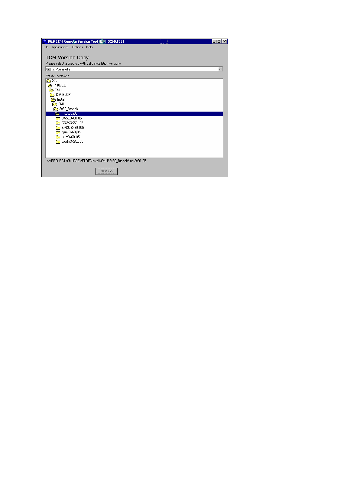
3. In the Version directory of the main application window, select the folder
from where you want to copy your software version and click Next >>>.
1100.4961.62 1.20 E-3
Page 35

R&S CMU 200 Software Update and Version Management
4. Select the software version you wish to install and click Start >>>.
The software version is copied to the internal drive C:\INTERNAL\INSTALL of
your R&S CMU. In addition, a text file named Versions.new (see section File
Versions.new on p. 1.27 ff.) is generated and copied to the same directory.
With default installation options (see figure above), the following happens after
the file transfer is completed:
• The CMU is rebooted and the new software version is installed and
activated (a key code must be entered once when a new software package
is installed; see section Hardware and Software Options in chapter 4 of the
operating manual).
• The Remote Service Tool is closed automatically.
Old software versions are not affected. You can delete or activate an old
software version using the VersionManager (see p. 1.29 ff.).
Note: You can also copy a software version to the internal hard disk and
use the VersionManager for the installation.
1100.4961.62 1.21 E-3
Page 36

Software Update and Version Management R&S CMU 200
Listing and
modifying software
versions
The Remote Service Tool can not only install firmware versions but also display
and modify the installed firmware configurations.
To list the firmware configurations installed on your CMU…
Click Application – List Software.
The list of installed versions has a tree structure. Each expandable node
contains a software configuration consisting of one base system version and
one or more network options. The active configuration is marked as (active)
and also displayed in the title bar of the Remote Service Tool. You can use the
controls on the left side to do the following:
• Select a configuration in the list and click Activate to label the configuration
active.
• Select a configuration in the list which is not the active configuration and
click Delete to label the configuration deleted. Repeat this for all
configurations you wish to delete.
Labeled configurations are not deleted immediately. You can simply Restore
any configuration that you labeled inadvertently.
Click Perform Actions to activate and/or delete the labeled configurations.
The labeled configurations are written to the Versions.new text file (see section
File Versions.new on p. 1.27 ff.) which is copied to the internal drive
C:\INTERNAL\INSTALL of your R&S CMU. In the default configuration where
Force device reboot is enabled, the R&S CMU is rebooted immediately so that
the VersionManager can activate and delete the labeled configurations.
Tip: Disable Force device reboot in case you wish to postpone the
actions until next time you switch on your instrument.
Copying files To transfer a file from the CMU to the PC or vice versa…
1. Switch on and start up your R&S CMU.
2. Select Applications – File Transfer from the menu bar of the Remote
Service Tool.
The main application window shows the directories and files on your PC and on
the INTERNAL directory of the CMU’s hard disk.
1100.4961.62 1.22 E-3
Page 37

R&S CMU 200 Software Update and Version Management
3. Select a directory, a file or several files and use the commands in the
FileCtrl menu to initiate the file transfer. You can also right-click the file list
to open the equivalent context menu.
Extracting
screenshots
A screenshot transferred by means of the Remote Service Tool can be viewed
and copied to the clipboard so that you can use it in another application.
To generate, transfer and further process a screenshot…
1. Press the PRINT button on the front panel of the CMU to open the Print
dialog, select Internal WMF as a destination and specify a file name
<file>.wmf for the generated image file (without adding a path).
2. Press OK to write the file to the INTERNAL\USERDATA\PRINT directory of
the CMU.
3. Proceed as described above to transfer the file <file>.wmf from the CMU to
your PC.
4. Double-click the transferred file (alternative: select the file and press
Enter).
The Remote Service Tool acts as a viewer for the file:
5. Right-click to open a context menu and either copy or close the file.
1100.4961.62 1.23 E-3
Page 38

Software Update and Version Management R&S CMU 200
Remote control of
the R&S CMU
You can use the Remote Service Tool to transfer remote control commands or
command scripts to be executed on the R&S CMU.
To transfer a single command or command sequence…
1. Click Applications – Command to activate the remote control screen.
2. Select the appropriate function group in the Secondary address mapping
panel.
3. Enter a command in the Enter remote command… input field and press
Enter.
4. Repeat steps 2 and 3 for all commands you wish to execute.
To execute a command script…
5. Generate an ASCII text file of remote control commands, either manually
or by saving a previously transferred command sequence (Save… button
in the remote control screen.
6. In the remote control screen, click Load… and open the file.
The script is transferred and executed automatically. The remote control
screen provides further control elements to make the command transfer more
convenient; see section Remote Control of the R&S CMU on p. 1.26 ff.
1100.4961.62 1.24 E-3
Page 39

R&S CMU 200 Software Update and Version Management
Table 1 Overview of R&S
Menu Command Function
File
Application
Options
Help
Close Close the Remote Service Tool.
Version Copy Copy a software version to the R&S CMU. See the application
List Software Display of all software configurations installed on the R&S CMU
Command Transfer of remote control commands or command scripts to be
File Transfer Transfer of data between a PC and the R&S CMU. This
Error Reports For future extensions
Use GPIB Use the GPIB bus for communication with the R&S CMU.
USE RS232 Use the RS232 bus for communication with the R&S CMU.
GPIB Options Change GPIB connection parameters. The default settings for the
RS232 Options Change RS232 transmission parameters. The following settings
Device Clear Clear the screen.
Go to Local Exit remote control mode and return to manual operation.
Device Reboot Reboot the R&S CMU.
About Shows an information box with the current version of the Remote
Remote Service Tool functions
example Installing software versions above.
and activate and/or delete configurations. See the application
example Listing and modifying software versions above.
executed on the R&S CMU. This command activates an additional Cmd Ctrl menu to generate log files and customize the screen. See application example Transferring remote control commands above and section Remote Control of the R&S CMU on p. 1.26 ff.
command activates an additional FileCtrl menu to create
directories, copy or delete files. See application examples
Copying files and Extracting screenshots above.
Note: This communication mode is recommended.
Note: Use the RS 232 Options quoted below if you choose this
communication mode.
R&S CMU are:
Board Index: 0
Primary Address: 20
Note: The GPIB settings of the Remote Service Tool and of the
R&S CMU must be the same. Refer to section Connecting a
Controller on p. 1.15 to learn how to configure the R&S CMU’s
GPIB settings.
ensure a reliable connection:
Baud Rate: 115200
Data Bits: 8
Stop Bits: 1
Parity: None
Protocol: CtsRts (do not change! )
Note: The RS232 settings of the Remote Service Tool and of the
R&S CMU must be the same. Refer to section Connecting a
Controller on p. 1.15 to learn how to configure the R&S CMU’s
RS232 settings. Should you experience any problems with the
data transfer, first check and possibly exchange the connecting
cable.
Service Tool.
1100.4961.62 1.25 E-3
Page 40

Software Update and Version Management R&S CMU 200
Remote Control of the R&S CMU
The remote control screen transfers remote control commands or command scripts to be executed on
the R&S CMU; see application example Remote control of the R&S CMU on p. 1.24. It is opened by
clicking Application – Command.
Fig. 1-10 Remote control screen
The commands to be executed are entered in the Enter remote command… input field; the responses of
the R&S CMU and possible error messages are displayed below. Besides the remote control screen
provides the following control elements:
Execute all
commands
Report Display /
Report File
Load / Save
Clear
Refresh sec.
address mapping
While the remote control screen is active, an additional Cmd Ctrl menu is available:
Execute all commands entered since the Remote Service Tool was started or
since the list was cleared. The complete command list appears in a pull-down
list associated with the Enter remote command… input field.
Display the remote report on the R&S CMU’s remote screen and create a
report file. These functions are identical with the Report Display and Report
File hotkeys in the CMU’s remote screen.
Load an ASCII text file (default extension: *.lst, can be changed at will), with a
command script to be executed or save the current command list to a text file
file.
Clear the current command list.
Refresh the list of assigned secondary addresses and function groups, e.g.
after the mapping was changed on the R&S CMU. Commands are sent to the
secondary address selected in the list.
1100.4961.62 1.26 E-3
Page 41

R&S CMU 200 Software Update and Version Management
Table 2 Overview of Cmd Ctrl menu in the Remote Service Tool
Command Function
Filename…
Logging Toggle function: Enable or disable logging.
Append File Toggle function: If enabled, new information is appended at the end of the log file. Otherwise the log
Button Setup Open a dialog to create command buttons, to be used as shortcuts for manual entry of frequently
Call up an Open File dialog to define the name and location of a log file containing all executed
commands and device responses. The responses can be up to 2 MByte in size, so the log file
information is often more complete than the remote report displayed on the instrument’s remote
screen.
file is overwritten at the beginning of each Remote Service Tool session.
used commands. The command buttons idn, opc, and Reset in Fig. 1-10 on p. 1.26 are created as
follows:
File Versions.new
The Versions.new file stores the software configurations that the R&S CMU VersionManager has to
install, delete, or activate. The following Versions.new file initiates the installation of a software
configuration containing a base system, a GSM network option package, and a IS136 package:
BASE3x60.i35
GSMS3x60.i35
IS1M3x60.i35
Automatic Install
Creating a
Versions.new file
Restrictions
The file is most conveniently created using the Remote Service Tool; see
application examples Installing software versions on p. 1.20 and Listing and
modifying software versions on p. 1.22. The Remote Service Tool also copies
the file to its location on the CMU’s internal hard disk (C:\INTERNAL\INSTALL)
so that it will be executed when the VersionManager is started.
Alternatively, the file can be created manually and copied to the
C:\INTERNAL\INSTALL directory or to the root directory of a PCMCIA
card/floppy disk.
The information in the Versions.new file must be unambiguous: Only one
software configuration with 1 base system software can be installed at once.
Alternatively, the file may list several network options to be combined with an
already installed, compatible base system version.
1100.4961.62 1.27 E-3
Page 42

Software Update and Version Management R&S CMU 200
Only one software configuration can be active, however, several configurations
can be deleted together. To avoid errors, it is recommended to use different
files for installation and deletion/activation.
Typical application Copy a Versions.new file to the root directory of a PCMCIA card containing
several installation versions and insert the card into the R&S CMU’s
PCMCIA slot.
After the instrument is booted, the VersionManager is started automatically and
installs the software packages listed in the file.
1100.4961.62 1.28 E-3
Page 43
R&S CMU 200 Software Update and Version Management
CMU VersionManager
The VersionManager is a tool designed to activate, delete, install, combine, or list different software
versions in a convenient way. Moreover, it provides information on the hardware and software
configuration of the instrument (Edit service tables, Scan disk), resets the startup settings stored in the
non volatile ram, copies information to an external storage medium (Write log files to disk, List all
versions to disk), and loads and activates user correction tables (see section Chapter 1 of the complete
operating manual).
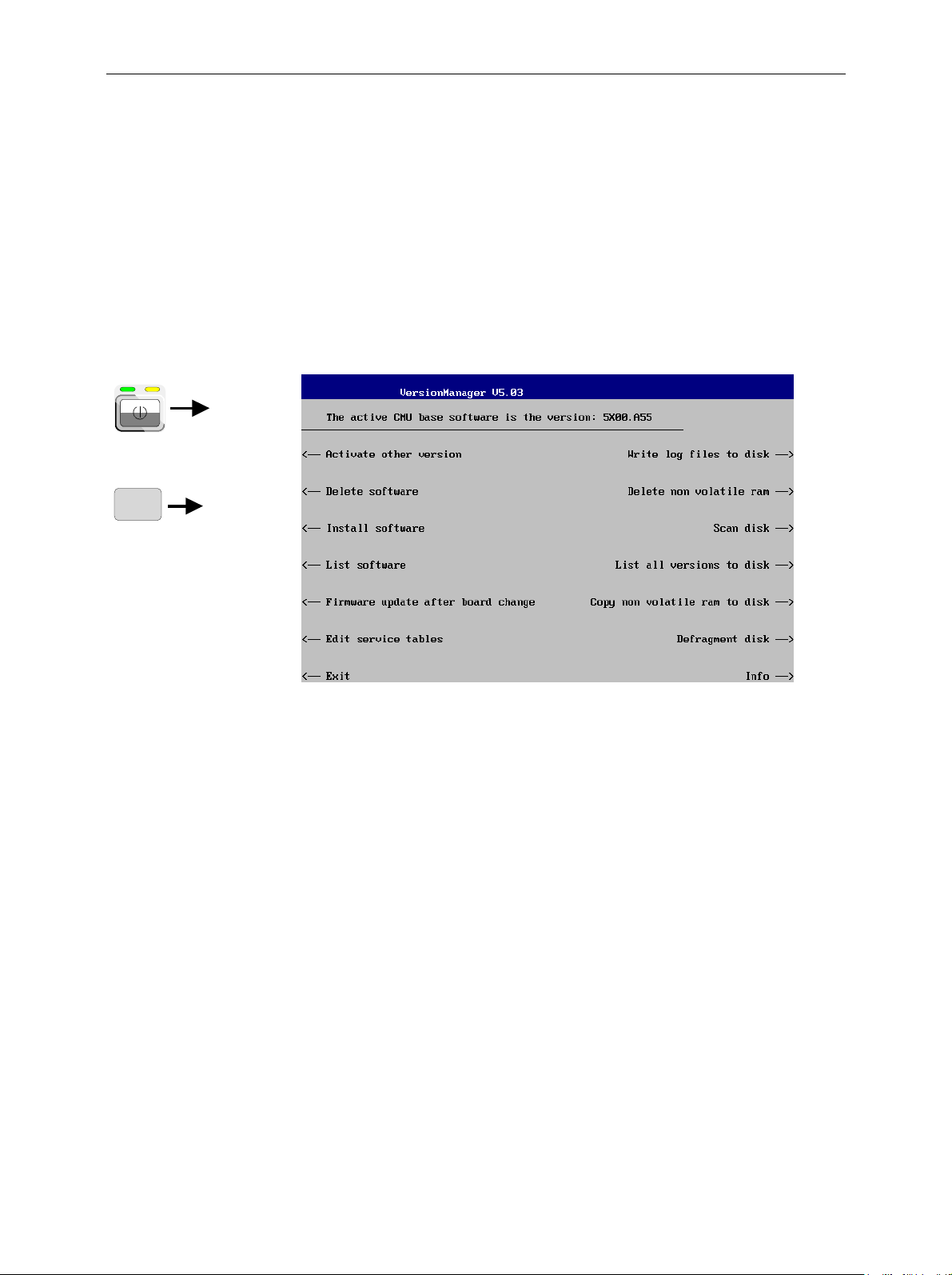
The VersionManager is part of each CMU firmware version. It is opened automatically after the boot-up
process if the CMU detects a storage medium in its floppy disk drive/PCMCIA slot that contains an
installation version of the CMU firmware. Alternatively, it can be called up by pressing the Menu Select
key after the boot-up sequence is terminated (from the moment when the CMU display turns black until
the end of the 3-beep acoustic signal).
with floppy / PCMCIA
card or
MENU
SELECT
Fig. 1-9 VersionManager main screen (example)
The different functions of the VersionManager are activated by pressing the corresponding softkeys.
Some of them (labeled optional below) are available in a particular configuration of the hard disk only.
The upper two softkeys in both softkey bars are not assigned.
Activate other version
(optional)
Activate other version opens a list of all firmware configurations stored on the
CMU hard disk except the current configuration. Therefore, this function is
not available if the hard disk contains only a single configuration (to retrieve
information, List software can be used instead).
1100.4961.62 1.29 E-3
Page 44

Software Update and Version Management R&S CMU 200
Each entry in the list corresponds to a firmware configuration consisting of
Delete software
(optional)
exactly one CMU base software version (top level on the left side) plus a set
of associated options
activated is displayed in red color on top of the list. To select another version,
the list can be scrolled using the rotary knob or the cursor keys.
Activate Activate the current firmware configuration.
Back to previous screen Close the current screen and go back to the main
Info Open the Info screen associated with the current
Delete software opens a list of all firmware configurations stored on the CMU
hard disk. The dialog can be operated as explained above; see Activate
software. The last firmware configuration can not be deleted, so this function
is not available if the hard disk contains only a single configuration.
1
(network tests, second level). The version to be
screen. This option is identical in all
VersionManager submenus.
screen; see Info on p. 1.37. This option is
identical in all VersionManager submenus.
Delete Delete the current firmware configuration.
1
Several related options may be displayed in a single line. These combinations of options can be installed together and will be simply referred to as "options" through the
remainder of this section.
1100.4961.62 1.30 E-3
Page 45

R&S CMU 200 Software Update and Version Management
If the active firmware configuration is deleted, the CMU asks which of the
remaining versions shall be activated:
Activate Activate the current firmware configuration.
Install software
Install software opens a list of all firmware installation versions available on
an internal or external storage medium that is accessible from the R&S CMU
(floppy disk/PCMCIA card). As explained in Table 1-3, this function depends
on the type and number of storage media and on the number of installation
versions available.
Table 1-3 Software installation with the VersionManager
Storage medium with FW
installation version
Floppy 1
PCMCIA card
in slot 0 or 1 (right or left side)
PCMCIA card
in slot 0 and in slot 1
Internal drive 1
2
PC-card
selection dialog:
Number of FW
installation versions
several
1
several
1 (per PC-card)
several
several
VersionManager function
Install software version <version> from floppy
Install software from floppy
–> Open software version selection dialog (see below).
Install software version <version> from PC-card slot <slot_no>
Install software from PC-card slot <slot_no>
–> Open software version selection dialog (see below).
Install software version <version> from PC-card
–> Open PC-card selection dialog (see below).
Install software from PC-card
–> Open PC-card selection dialog (see below).
Install software version <version> from internal drive
–> Open PC-card selection dialog (see below).
Install software from internal drive
–> Open PC-card selection dialog (see below).
The PC-card selection dialog selects either PCMCIA card slot 0 (right side)
or slot 1 (left side) for installation.
2
Media without FW installation versions are ignored.
1100.4961.62 1.31 E-3
Page 46

Software Update and Version Management R&S CMU 200
Install software... Select the card in slot 0 or slot 1 as an installation
medium. If the medium contains several installation
versions, the software version selection dialog is called up,
see below.
Rescan Drives… Rescans the external and internal drives in order to detect
new software installation versions and update the screen
accordingly.
Software version
selection dialog:
The software version selection dialog lists all installation versions on the
current medium (floppy, PCMCIA card). The dialog can be operated as
explained above; see Activate software.
Install Install the current firmware version.
Upgrade options:
1100.4961.62 1.32 E-3
In contrast to the Activate software dialog, the software selection dialog
handles base software versions and network options separately. As a
consequence, different versions of the base software can be combined with
different options to create new firmware configurations. For example, it is
possible to update the base software without affecting the associated
network options or vice versa. Moreover, the same base software version
can be installed several times and combined with different network options
(and vice versa), so it may enter into several firmware configurations. The
Page 47

R&S CMU 200 Software Update and Version Management
following simple rules apply:
• With a new version of a network option, it is only possible to update one
of the existing configurations. The following selection dialog is
automatically skipped.
• With a new base software version, it is possible to either update an
existing configuration or create a new one. A dialog selecting between the
two alternatives is opened:
Note: This dialog is skipped if the new base software
version is not compatible with any of the existing
configurations. An incompatible new base software
must be installed as a new base software.
Install as new base Create a new configuration based on the base
software to be installed. The upgrade selection dialog
described below is skipped. Network options can be
assigned to this base software in a second stage of
the installation.
Upgrade existing v. Select an existing configuration and replace the base
software of this version. To this end, the upgrade
selection dialog described below is opened.
Force Verm update If the option is checked the current VersionManager is
overwritten every time that a new base system is
installed, even if this means a downgrade of the
VersionManager version. This feature is primarily for
service purposes.
After selection of an upgrade software version compatible with one of the
configurations stored on the hard disk, the upgrade selection dialog is called
up:
1100.4961.62 1.33 E-3
Page 48

Software Update and Version Management R&S CMU 200
Upgrade Replace the base software version or network option selected
in the software version selection dialog.
Alternatively, if none of the configurations stored on the hard disk is
compatible with the software version selected, an error message is
displayed. E.g., for an incompatible Bluetooth version:
Back to... Close the current screen and go back to the software version
selection dialog to select a compatible software version.
Terminating the
software update:
1100.4961.62 1.34 E-3
After successful installation of each software version the CMU displays the
following screen:
Page 49

R&S CMU 200 Software Update and Version Management
Install next software... Go back to the software version selection dialog to
select additional software modules to be installed in
the same VersionManager session. This function
depends on the storage media and the number of
software installation versions available; see Table 1-3
on page 1.31.
Rescan Drives… Rescans the external and internal drives in order to
detect new software installation versions and update
the screen accordingly.
Finish installation Close the VersionManager and reboot the CMU
(remove the external disk from the disk drive). The
installed firmware configurations are then operational.
The last configuration installed is taken as the active
configuration in the subsequent measurement
session.
Lack of disk space:
Note: Notice messages after firmware updates
In most cases firmware updates do not affect the accuracy of the
measurements. There are some exceptions where a correction procedure
must be executed in the Maintenance menu after the firmware update. The
R&S CMU displays a notice message whenever this happens. The box
contains the name of the required correction procedure and appears during
startup until the correction has been performed.
Before installing the next software version, the CMU checks whether there is
enough disk space on the hard disk. If not, the following dialog is displayed:
1100.4961.62 1.35 E-3
Page 50

Software Update and Version Management R&S CMU 200
Delete Delete the current version and return back to the
previous screen.
List software
List software opens a list of all available firmware configurations. It is
possible to activate and delete configurations from the list; see description of
Activate software and Delete software functions above.
Firmware update after
board change(…)
1100.4961.62 1.36 E-3
This function depends on whether a user correction file named
USERCOR1.DAT is stored in the directory INTERNAL\USERCOR\ of the
internal hard disk.
• If no user correction file is available, Firmware update after board change
performs an update of the current firmware including a complete CMU
hardware detection. No external installation disk is required. The update
takes some time and should be attempted in case of problems or after a
modification of the CMU hardware configuration only (also after a
combined hardware/software exchange).
• If a user correction file is found, Firmware update after board change…
opens a submenu to activate or deactivate the RF user correction; see
section Chapter 1 of the complete operating manual.
Page 51

R&S CMU 200 Software Update and Version Management
Edit service tables
Exit
Write log files to disk
Delete non volatile
ram
Edit service tables calls up the Service Table Editor menu showing all
hardware modules that are possibly fitted in your instrument. For service
purposes, further information can be obtained by typing a particular board
name and board index in the two lines below the table.
Exit closes the VersionManager and resumes the CMU start-up procedure.
Write log files to disk copies all *.log files stored on the CMU hard disk to an
external storage medium (floppy or PCMCIA card). The *.log source files on
the hard disk are not deleted.
The Write log files to disk function opens a blue message box indicating the
storage capacity of the external disk needed. The *.log files can be
distributed over several disks. If no disk is available, the VersionManager
displays a warning and does not start copying.
Delete non volatile ram deletes all entries stored in the non volatile ram of the
CMU. This memory contains particular settings of the last CMU session that
can be reused in the next session (e.g. the last active function group and
measurement menu, special configuration etc.).
Deleting the non volatile ram can be useful after an abnormal termination of
a CMU measurement session.
Note: The settings stored in the non volatile ram can also be written to
a configuration file and reused in later sessions; see Chapter 3
of the operating manual, section Saving Configurations.
Scan disk
List all versions to
disk
Copy non volatile ram
to disk
Defragment disk
Info
Scan disk closes the VersionManager, executes the MS Scan Disk program
and finally returns you to the VersionManager. Refer to your Scan Disk
documentation for further information.
Note: This function is not available while a base software version
<V3.00 is active.
List all versions to disk writes the software configurations indicated via List
software to an ASCII text file that is stored on the external disk.
Copy non volatile ram to disk copies the contents of the non volatile ram to
the external disk (floppy, PCMCIA).
In this way, the settings stored in the non volatile ram can be used on
another CMU.
Defragment disk closes the VersionManager, executes the MS Defrag.exe
program and finally returns you to the VersionManager. Defragmenting the
hard disk is suitable to improve performance after installing and deleting
many different software versions. Refer to your Defrag.exe documentation
for further information.
Note: This function is not available while a base software version
<V3.00 is active.
Info opens an output window displaying information on the current screen.
Separate Info windows are provided for the different VersionManager
dialogs.
1100.4961.62 1.37 E-3
Page 52

Software Update and Version Management R&S CMU 200
Escape Close the Info screen and return to the previous screen.
Error and notify
message
During operation, the VersionManager can display two different types of
messages:
• Error messages indicating that an action could not be successfully
performed are displayed in yellow boxes. All error messages with
possible reasons and remedial actions are explained in Chapter 9 of the
operating manual.
• Notify messages describing ongoing processes of the instrument are
displayed in blue boxes. These messages are self-explanatory and do not
require an action to be taken by the user.
1100.4961.62 1.38 E-3
Page 53

R&S CMU 200 Contents of Chapter 2
Contents
2 Getting Started .................................................................................................... 2.1
A Short Tutorial on CMU Operation................................................................................................2.1
Condensed Operating Instructions...........................................................................................2.1
How to access and close menus..............................................................................................2.2
How to use dialog elements in the menus ...............................................................................2.3
Startup of the CMU ...........................................................................................................................2.4
RF Measurements.............................................................................................................................2.8
1100.4961.62 I-2.1 E-1
Page 54

Page 55

R&S CMU 200 A Short Tutorial on CMU Operation
2 Getting Started
The following chapter presents a sample session with the universal radio communication tester CMU. It
is intended to provide a quick overview of the settings provided in the base system and the RF function
group. No specific device under test is required. For an introduction to mobile network tests (e.g. tests of
GSM900/1800/1900 mobile phones) please refer to the relevant operating manuals.
Before starting any measurement with the CMU, please note the instructions given in Chapter 1 for putting the instrument into operation. In this chapter and in Chapters 3 to 4 of the complete operating manual you will find detailed information on customizing the instrument and the display according to your
personal preferences.
The steps to perform are explained on the left side of each double-page together with the results obtained on the CMU screen. On the right side, additional information is given. We also point out alternative settings and related measurements which could not be reported in detail.
For a systematic explanation of all menus, functions and parameters and background information refer
to the reference part in Chapter 4 of the operating manual.
A Short Tutorial on CMU Operation
The principles of manual operation – controls, operating menus, dialog elements and measurement
control – are discussed in Chapter 3 of the operating manual. Below we list some essentials for first
users:
Condensed Operating Instructions
1. Press the RESET key on the front panel to set the instrument to the default state before you config-
ure a new measurement.
2. Press ENTER to confirm selections, even if No or Yes is displayed.
3. The MENU SELECT front panel key can be pressed in any state of the unit. A large popup menu is
then displayed in which the function group (network etc.), signalling mode, and measurement
menus can be selected. Activate by pressing ENTER.
4. A front-panel LED indicates which of the RF connectors is configured as output. In the menu, the RF
generator can be activated or deactivated with ON/OFF (green/red). The front-panel LED goes out if
the generator is in the OFF position.
5. A front-panel LED indicates which of the RF connectors is configured as input. In the menu, the
measurement can be controlled via the ON/OFF and CONT/HALT keys (ON (green), OFF (red) and
HLT (yellow) states). In the OFF state, the LED goes out.
6. The SETUP hardkey allows to make static, measurement-independent default settings such as
Remote or Time, to check which options are installed and to activate new software options.
7. The softkeys to the right of the menus are used to change the hotkeys across the bottom and their
functions. Pressing the Menus softkey (bottom right) allows a fast switchover between related
menus using the hotkeys.
1100.4961.62 2.1 E-1
Page 56

A Short Tutorial on CMU Operation R&S CMU 200
How to access and close menus
A startup menu is displayed automatically when the CMU is switched
on.
SETUP
Some general configuration and selection menus can be opened via the
MENU SELECT, RESET, INFO, PRINT, HELP or SETUP keys on the
front panel.
The hotkeys displayed across the bottom of a main menu or graphical
measurement menu are used to switch over between different main
menus or graphical measurement menus. Tabs in popup menus are
also accessible via hotkeys.
The Connect. Control softkey (always at the top right) is available in all
measurement menus. This softkey opens a popup menu defining the
input and output connectors, the external attenuation, the reference
frequency as well as many network-specific settings.
In the Signalling test modes of many network options, the Connection
Control menu is also used to set up and terminate a connection between the CMU and the DUT.
The Connection Control menu also contains the input path and the trigger settings for the current function group and signalling state.
If a special configuration menu exists for a measurement or for a generator the corresponding softkey is marked with a yellow arrow. The
configuration menu is opened by pressing the softkey twice.
ESCAPE
1100.4961.62 2.2 E-1
All CMU popup menus can be closed with the ESCAPE key.
Main menus and graphical measurement menus are closed on switching to another main or graphical measurement menu.
Page 57
R&S CMU 200 A Short Tutorial on CMU Operation
How to use dialog elements in the menus
The dialog elements assigned to a softkey are selected by pressing the
softkey.
Different input fields can be selected by means of the 4 cursor keys
(blue frame shows active input field).
One of several elements in a list or toggle switch can be selected with
the rotary knob.
Numeric values can be either incremented/decremented using the rotary knob or entered via the numeric keypad or an external keyboard.
For a comprehensive introduction to manual operation of the CMU refer to Chapter 3 of the operating
manual.
1100.4961.62 2.3 E-1
Page 58

Startup of the CMU R&S CMU 200
Startup of the CMU
This section describes how to customize the CMU and perform simple RF measurements. As a prerequisite for starting the session, the instrument must be correctly set up and connected to the AC power
supply as described in Chapter 1.
o
I
Step 1
Switch on the CMU using the mains
switch at the rear.
Check the operating mode of the instru-
ment at the ON/STANDBY key on the
front panel. If the CMU is in standby
mode, press the ON/STANDBY key.
RESET
Step 2
The CMU is booted and after a short while
displays the startup menu. This menu is
usually closed as soon as the instrument
software is loaded and the startup test is
finished.
Press the Wait hotkey to prevent the
instrument from switching to another
menu.
The Wait hotkey changes to Cont. with the
additional message Change to last menu
displayed on top.
Press the Cont. hotkey to resume the
startup process.
Step 3
Press the RESET key to open the Reset
popup menu.
Proceed as described in Chapter 4 of the
operating manual, section Reset of In-
strument Settings, to expand the tree of
function groups.
Select the function groups Base and RF
to be reset (the corresponding nodes
must be black).
Use the cursor keys to activate the Reset
button and press ENTER.
In the popup window opened (Are you
sure?), select Yes to confirm the instru-
ment reset.
The CMU indicates that it performs a partial
reset of the two selected function groups and
is then ready to carry out the following steps.
The Reset popup menu is closed automatically.
1100.4961.62 2.4 E-1
Page 59

R&S CMU 200 Startup of the CMU
function can be used to access
Additional Information... Alternative Settings
and Measurements
... on Step 1
Mains switch on the rear panel
When the mains switch at the rear is set to the O position, the
complete instrument is disconnected from the power supply.
When the mains power switch is set to the I position, the instrument is in standby mode or in operation, depending on the
position of the ON/STANDBY key on the front panel.
ON/STANDBY key on the front panel
The ON/STANDBY key at the front of the instrument determines whether the instrument is in standby mode or in operation.
Standby mode:
Only the OCXO reference frequency oscillator (option CMUB11/B12), if installed, is supplied with operating voltage. The
orange LED (STANDBY) is illuminated.
Operation:
The green LED (ON) is illuminated and all modules of the instrument are supplied with operating voltage.
... on Step 2
Chapter 1
The CMU is automatically set to
the AC supply voltage and frequency applied. Note the permissible ranges of AC voltages and
frequencies indicated at the rear
of the instrument and in the data
sheet.
Chapter 1
The behavior of the CMU when it
is switched off depends on the
Front Module controller type installed.
Startup menu
The startup menu displays the following information:
• The startup procedure (Process)
• Instrument model, serial number and version of the CMU
base software (Info).
• Installed hardware and software options and equipment
(Options). Available software options are listed with their
version numbers.
• Progress of the startup procedure (Startup bar graph).
Wait hotkey
By default the CMU switches to the last main menu of the
previous session after terminating the startup process. This is
convenient if an interrupted session is to be resumed or if the
instrument is generally used in a definite operating mode.
On the other hand, the Wait
the configuration menus which can be opened by means of
the front panel keys before the actual measurement is
started.
While the Wait hotkey is active, a reset of the instrument is
not possible.
Chapter 4 of the operating
manual
The Default hotkey can be used
to load the factory default settings
for all function groups. Settings
made and stored in the previous
session are overwritten.
The CMU’s user interface has
been optimized with the aim of
facilitating fast and easy switchover between the menus and
measurement modes. This includes the general configurations
which can be accessed from any
measurement menu.
The most important selection and
configuration menus such as Re-
set, Setup, Menu Select etc.are
directly accessible via front panel
keys.
1100.4961.62 2.5 E-1
Page 60

Startup of the CMU R&S CMU 200
SETUP
Step 4
Press the SETUP key to access general
device settings.
Press the Time hotkey to switch over to
the Time tab of the Setup menu.
Step 5
The Time tab of the Setup menu displays the
current time zone, time and date.
Use the rotary knob to move the focus
onto the Time section of the Setup table.
If necessary, press the rotary knob or the
ON/OFF key to expand the parameters in
the table (see Chapter 3 of the operating
manual).
Move to one of the input fields associated
to the Time parameter, select with
ENTER and use the rotary knob or the
numeric keypad to correct the settings for
the current time. Hours, minutes and
seconds can be edited separately.
Press ENTER to confirm the entries and
quit the input fields.
Move to Zone select field, activate with
ENTER, and use the rotary knob to
choose your own time zone.
In the same way, activate the Format
select field and use the rotary knob to
switch over between European and North
American time conventions.
1100.4961.62 2.6 E-1
Page 61

R&S CMU 200 Startup of the CMU
Additional Information... Alternative Settings
and Measurements
... on Step 4
Softkeys and hotkeys
Softkeys and hotkeys are activated by pressing the associated keys on both sides and across the bottom of the display.
The general purpose of softkeys is to provide settings, control
the generator and the measurements. Hotkeys are used to
switch over between different menus and different tabs belonging to a popup menu.
... on Step 5
Setup menu
The Setup menu comprises several tabs providing general instrument settings. It is advisable to check and adjust the factory settings when you operate the CMU for the first time.
To switch over between the tabs of the setup menu use the
hotkeys displayed at the bottom of the display.
Chapter 3 of the operating
manual
Chapter 4 of the operating
manual
The different types of menus and
control elements of the graphical
user interface is explained in
Chapter 3 of the operating manual. In the same chapter you can
find a short tutorial on the entry of
numbers and characters.
1100.4961.62 2.7 E-1
Page 62

RF Measurements R&S CMU 200
RF Measurements
In the RF function group, a continuous or pulsed RF signal can be generated and a RF signal with definite frequency characteristics can be analyzed. The signal level can be plotted in oscillographical
(Power) or spectral (Spectrum) representation.
MENU
SELECT
Step 1
Press the Menu Select key to open the
Menu Select menu.
Use the cursor keys and the rotary knob
to select the RF function group in the
left half of the Selection table.
In the right half of the table, select the
Analyzer/Generator menu.
Press the Enter key to activate the
measurement selected and open the
RF Analyzer/Generator menu.
Step 2
In the Settings table the Analyzer/Generator menu indicates the pa-
rameters of the signal generated and those
of the signal received and analyzed.
At present, all parameters have been reset
to factory default values. Different softkey/hotkey combinations and popup menus
are provided to change the settings. Userdefined parameters will be saved for later
sessions when the CMU is switched off.
The Power output field in the Ana-
lyzer/Generator menu shows an invalid
result ("---") because at present no RF
input signal is applied to the CMU.
1100.4961.62 2.8 E-1
Page 63

R&S CMU 200 RF Measurements
Additional Information... Alternative Settings
and Measurements
... on Step 1
Menu Select menu
The Menu Select menu shows all function groups installed on
your CMU. If a function group is selected the available test
modes and measurement menus are indicated. Function
groups representing digital network tests (such as
GSM400/850/900/1800/1900-MS) are generally subdivided in
the two test modes Non Signalling and Signalling, each containing a number of measurement menus.
The RF function group is available on any CMU regardless of
the software options purchased. It comprises the three measurement menus Analyzer/Generator, Power and Spectrum.
All three measurement menus are directly accessible from
the Menu Select menu.
... on Step 2
Analyzer/Generator menu
The Analyzer/Generator menu contains several softkeys to
• Control the RF signals received and analyzed (Analyzer
Level, Analyzer Settings)
• Control the RF signals generated (Generator)
Defining a level and frequency via the Generator softkey and
the associated hotkeys implies that a continuous signal (CW)
with this level and frequency is generated.
The RF Max. Level defined via Analyzer Level, however, denotes the maximum input power which can be measured.
This is identical with the upper edge of the Power diagram
(see below). The permissible range of Max. Level depends on
the input connector and external attenuation used (see section Analyzer Settings in Chapter 4).
Chapter 4 of the operating
manual
For digital network tests refer to
the relevant operating manuals.
e.g. GSM400/850/900/1800/1900-
MS.
manual
The Generator softkey provides
the most important settings of the
Generator tab of the Connection
Control menu.
The Analyzer Level and Analyzer
Settings softkeys correspond to
the Analyzer tab of the Connection Control menu.
Chapter 4 of the operating
Defining a (center) Analyzer Settings – Frequency implies
that only signals around this frequency are analyzed.
The Analyzer Settings – RBW hotkey defines the resolution
bandwidth of the analyzer.
The status of the Analyzer Power measurement is shown in
the corresponding softkey. For ongoing measurements, the
result in the Power output field is constantly updated.
At present no input signal is available so that the Power output field shows an invalid result “– – –“
Once the softkey is selected, the Analyzer Power measurement can be switched off and on by means of the ON/OFF
key. In contrast, the CONT/HALT toggle key halts the measurement after the next valid result has been obtained.
1100.4961.62 2.9 E-1
The options for the measurement
status are ON, OFF, or HLT. The
HLT state is reached after the end
of a single shot measurement
(see the section about measurement control in Chapter 5 of the
operating manual).
Ch. 4 and Ch. 5
Page 64

RF Measurements R&S CMU 200
Step 3
Press the Connect. Control softkey and
use the Generator hotkey to open the
Generator tab.
The Generator tab controls the RF generator and defines the Frequency and Modula-
tion of the generated RF signal.
Select the Generator softkey by press-
ing once.
Press the ON/OFF key to switch the RF
generator on.
Set the generator frequency equal to the
default frequency of the RF analyzer
frequency as shown in the figure.
Press the RF
defining the signal connectors and external attenuation.
hotkey to open the tab
Select RF 2 as output connector, RF 4
IN as input connector. Do not define any
external attenuation (all values equal to
0.0 dB).
Two yellow LEDs on the front panel indicate the input and output connectors selected.
Use a coax cable to connect RF 2 to RF
4 IN.
Press the ESCAPE key to close the
popup menu and return to the RF Ana-
lyzer/Generator main menu.
The RF level measured is now indicated
next to the Analyzer Power softkey. Due to
the loss in the signal path it should be
slightly below the generator power se-
lected.
Reopen the Connection Control menu
and press the Generator softkey twice.
The table-oriented version of the Generator
tab is opened.
Press ON/OFF to expand the parameter
tree, use the rotary knob to select the
Ramping parameter, press Enter and
use the rotary knob again to switch the
power ramping ON.
Now the generator transmits a pulsed (instead of a continuous) signal.
Press the Connect. Control softkey
again or the ESCAPE key to close the
popup menu.
1100.4961.62 2.10 E-1
Page 65

R&S CMU 200 RF Measurements
Additional Information... Alternative Settings
and Measurements
... on Step 3
RF connectors
The RF Connection Control menu configures the input and
output connectors in the RF function group. The four connectors on the front panel differ by their permissible range of input and output powers (see Chapter 4 of the operating manual and data sheet). The values quoted on the left side are
compatible with the rated specifications.
External attenuation
An external attenuation can be reported to the CMU in order
to compensate for known losses between the signal source
and the device under test or the analyzer.
In our example, the (positive) difference between the analyzer
power measured and the generator power can be reported as
an external output attenuation at RF 2. The RF generator increases its level to maintain the commanded power of
–27 dBm at the analyzer. The nominal generator power set in
the RF level field is thus measured and indicated next to the
Analyzer Power softkey.
Note: RF User Correction
In addition to the static external attenuation settings, the
CMU provides systematic, frequency and leveldependent correction mechanisms of the generated and
measured RF power:
Settings made in the Connect.
Control menus apply to the entire
function group RF Non Signalling.
Note that an external attenuation
reported to the CMU shifts the
nominal permissible ranges of
input and output levels.
Chapter 4 of the operating
manual
Chapter 4 of the operating
manual
• In many function groups (e.g. the present RF group)
a frequency-dependent attenuation can be defined
after pressing Ext. Att. Output or Ext. Att. Input twice.
• Global, frequency and level-dependent correction
tables can be loaded using the VersionManager; see
section RF User Correction in Chapter 1 of the complete R&S CMU operating manual.
1100.4961.62 2.11 E-1
Page 66

RF Measurements R&S CMU 200
Step 4
Press the Power hotkey to switch over
to the graphical menu Power.
The Power menu shows the RF signal
power measured as a function of time at a
particular frequency and resolution bandwidth.
must be selected to obtain a stable display.
An appropriate trigger condition
Settings (default settings or the ones made
in the Analyzer/Generator menu) and scalar results are displayed in two parameter
lines above the diagram.
Various tools allowing to take a closer look
at the measurement results are provided in
the graphical measurement menu.
Press the Marker/Display softkey twice
and vary the Time Scale to display several pulses in the diagram.
Press the Analyzer Settings softkey and
vary the resolution bandwidth (hotkey
RBW).
Press the Menu softkey to display the
hotkeys used to change over to the
other measurement menus.
Press the Spectrum hotkey to switch
over to the graphical menu Spectrum.
Step 5
The Spectrum menu shows the signal
power in spectral representation, i.e. as a
function of the frequency.
The settings and results displayed in the
two parameter lines above the diagram are
analogous to the ones shown in the Power
menu.
Press the Marker softkey and use the
R to Pk and the Cnt to R hotkeys to cen-
ter the diagram.
Press the Analyzer Settings softkey to
scale the diagram and adjust the resolution bandwidth.
To close your session set the CMU to
standby mode using the power switch
on the front panel or use the mains
switch at the rear.
1100.4961.62 2.12 E-1
Page 67

R&S CMU 200 RF Measurements
Additional Information... Alternative Settings
and Measurements
... on Step 4
Trigger mode
The trigger mode is set in the Analyzer tab of the Connection
Control menu or via the Trigger softkey in the graphical
measurement menus. With the default setting Free Run the
measurement is not synchronized to the frequency of the incoming pulses: The trace is permanently shifted in horizontal
direction.
To show a signal consisting of rectangular pulses (bursts) it is
recommended to trigger by either the rising or falling edge of
the IF power.
Markers
Markers are a graphical tool used to locate points on a trace
and read out their coordinates. A reference marker and two
delta markers may be defined in the Power menu.
The reference marker
trace, the delta markers
tween their position and the reference marker. All marker coordinates are shown in the two parameter lines above the
diagram.
measures the absolute level of the
and measure the distance be-
Resolution bandwidth
A spectrum analyzer can differentiate two spectral lines separated by a minimum distance corresponding to the bandwidth
of the resolution filter.
The smaller the bandwidth the better the resolution and the
larger the signal-to-noise ratio. If the resolution bandwidth is
too large only the envelope of the spectrum can be measured.
In the Power measurement, the signal-to-noise ratio improves
but the time resolution deteriorates when the resolution
bandwidth is reduced.
... on Step 5
The Frequency softkey defines
the frequency of the measured
signal and the resolution bandwidth. The Input Level softkey
configures the input level, the
power range and an attenuation
factor. The Time softkey configures the time axis.
In addition to markers, a D-line
can be used to measure a particular level in the diagram.
Chapter 4 of the operating
manual
Chapter 4 of the operating
manual
Chapter 4 of the operating
manual
Scaling of the spectral diagram
The tools provided in the Spectrum menu are particularly
suitable for scaling a spectral diagram with a sharp main lobe
and symmetric, lower side lobes:
• The R to Pk hotkey (Marker softkey) places the reference
marker to the maximum (i.e. the main lobe) of the diagram.
• The Cnt to R hotkey (Marker softkey) centers the diagram
to the frequency of the main marker.
• Equivalently, the Center hotkey (Frequency/RBW softkey)
can be used to center the diagram.
1100.4961.62 2.13 E-1
Chapter 4 of the operating
manual
Page 68

Page 69

R&S CMU 200 Index
Index
List software ................................................................ 1.36
A
AC supply connection...................................................1.12
Activate other software.................................................1.29
B
Back to previous screen ...............................................1.30
C
Command Button (Remote Service Tool ......................1.27
Configuration, firmware ................................................1.29
Configure Command Buttons .......................................1.27
Connection
controller ..................................................1.15, 1.20, 1.25
external keyboard .......................................................1.17
IEC bus ......................................................................1.16
monitor.......................................................................1.17
RS-232.......................................................................1.16
Controller connection ...................................................1.15
Copy non volatile ram to disk .......................................1.37
D
Defragment disk ...........................................................1.37
Delete non volatile ram.................................................1.37
Delete software............................................................1.30
E
Edit service tables........................................................1.37
EMC.............................................................................1.14
Error messages, VersionManager................................1.38
Exit...............................................................................1.37
External keyboard ........................................................1.17
F
File transfer, Remote Service Tool ...............................1.22
Firmware configuration.................................................1.29
Firmware update ..........................................................1.19
Firmware update after board change ............................1.36
Front view ..................................................................... 1.1
Fuses ...........................................................................1.12
G
Getting Started.............................................................. 2.1
GPIB bus interface.......................................................1.15
I
IEC/IEEE bus................................................see GPIB bus
Info...............................................................................1.37
Input level.....................................................................1.14
Install software.............................................................1.31
Log file, Remote Service Tool...................................... 1.27
M
Main power switch................................................ 2.4, 2.12
Monitor ........................................................................ 1.17
N
Non volatile ram........................................................... 1.37
Notify message (VersionManager)............................... 1.38
Null-modem .................................................................1.16
P
PC-card selection dialog.............................................. 1.31
Power fuses................................................................. 1.12
Power switch ............................................................... 1.12
Putting into Operation ........................................... 1.1, 1.10
AC supply connection ................................................ 1.12
EMC ..........................................................................1.14
instrument setup ........................................................1.10
mounting in a rack ..................................................... 1.11
switching on............................................................... 1.12
R
Rack mounting............................................................. 1.11
RAM ............................................................................ 1.37
Rear view ...................................................................... 1.7
Remote control, Remote Service Tool ................ 1.24, 1.26
Remote Service Tool ...................................................1.19
S
Scan disk..................................................................... 1.37
Setting up (CMU) ......................................................... 1.10
Software installation, Remote Service Tool.................. 1.20
Software update .......................................................... 1.19
Software version selection dialog ................................1.32
Standby mode ...................................................... 1.12, 2.5
Startup menu........................................................ 1.13, 2.4
Switching on................................................................ 1.12
U
Upgrade firmware ........................................................ 1.32
V
Versions.new............................................................... 1.27
VGA monitor................................................................ 1.17
W
Write log files to disk.................................................... 1.37
L
List all versions to disk .................................................1.37
1100.4961.62 I.1 E-3
Page 70

 Loading...