


¸CMU200 Universal Radio Communication Tester
THE multiprotocol tester for current and future mobile radio networks
Extremely high-speed testing
◆
Highly accurate measurements
◆
Modular future-proof design
◆
Comprehensive spectrum analyzer
◆
Fast switching between networks
◆
Version
Version
09.00
08.00
November
November
2007
2007
2 ¸CMU200 Universal Radio Communication Tester
Testing the 3rd generation
For more than 70 years, Rohde & Schwarz
has always been at the forefront of
mobile radio technology. We continue
this tradition of RF test and measurement with the ¸CMU200 Universal
Radio Communication Tester. The
¸CMU200 is a third-generationplatform design that offers true scalable
multimode functionality.
The ¸CMU200 reflects the many
years of expertise Rohde & Schwarz has
gained in the world of mobile radio. In
recent years, the company has helped to
launch overwhelmingly successful mobile radio systems.
Rohde & Schwarz is a preferred supplier
to many of the leading mobile equipment manufacturers and is the market
leader for mobile radio test sets.
Low cost of ownership
Selecting the ¸CMU200 is a decision
for the future and results in a total cost
of ownership that is sure to be among
the lowest due to the following factors:
The completely modular design of
◆
hardware and software components
eliminates unnecessary investments
right from the start merely because
a feature might be needed at some
point in the future. You only pay for
what you need
Maximum production output in a
◆
compact 4-rack-unit-high package
with minimum power dissipation allows compact production space layout
If an expansion becomes necessary
◆
because your needs grow, the modularity of the ¸CMU200 concept
will make this easy. Many expansions
may be installed on site. You pay for
them only when you need them
With the intuitive ¸CMU200 user
◆
interface, even less experienced users do not require extensive training
A new remote interface syntax re-
◆
flects the inherent modularity of this
real multimode tester
The ¸CMU200 is part of a complete
range of mobile radio test equipment,
encompassing everything from conformance test systems to system simulators, turnkey functional board test/final
test systems and simple sales-counter
Go/NoGo testers.
The base unit with its standard-independent module test provides many generalpurpose measurement facilities for the
development of all kinds of standards
within its wide and continuous frequency range. If extended by the appropriate options, the ¸CMU200 offers
the hardware and software necessary to
handle your 3G, 2.5G and previous-generation testing applications, including
analog.
The ¸CMU200 targets a wide range of applications but is primarily optimized for the high
accuracy and speed demanded in increasingly quality-conscious manufacturing processes.
The picture shows the front panel for desktop use.

Applications
RF development
◆
Module design
◆
Module test in production
◆
Adjustment of mobile phones
◆
Final test in production
◆
Functional test
◆
Feature test
◆
High-end service
◆
Quality inspection
◆
Basis for test systems
◆
Base station simulation
◆

4 ¸CMU200 Universal Radio Communication Tester
Usability
The ¸CMU200 key
strengths
The ¸CMU200 Universal Radio Communication Tester brings premium cost
effectiveness through a variety of features, with extremely fast measurement
speed and very high accuracy being the
two most important ones. In addition,
the secondary remote addressing of the
tester‘s modular architecture makes for
intelligent and autonomous processing
of complete measurement tasks and fast
control program design.
Maximum accuracy
In a production environment, the tester‘s
high accuracy allows devices under test
(DUTs) to be trimmed for maximum battery lifetime without compromising quality. In the lab, the ¸CMU200 enables
the development engineer to partly replace conventional, dedicated premiumquality instruments and save desktop
space at the same time. High-precision
measurement correction over the entire
frequency and dynamic range as well as
compensation for temperature effects in
realtime are critical factors for achieving
the ¸CMU200‘s excellent accuracy.
The globally standardized Rohde & Schwarz
calibration system can check the
¸CMU200‘s accuracy at a service center close to you or, in some cases, on your
premises. A worldwide network of these
standardized automatic calibration systems has been implemented in our service
centers. Highly accurate and repeatable
calibration can be performed wherever you
are. Your local Rohde & Schwarz representative offers customized service contracts.
For large-scale users of the ¸CMU200,
a compact level verification system is available in addition.
Owing to the high resolution of the
extremely bright high-contrast TFT
display, even the finest details can be
displayed
Direct branching to all associ-
ated menus makes for a uniquely
flat menu structure
Top speed
The high processing speed is due to extensive use of ProbeDSP™ technology,
parallel measurements and innovative
remote command processing.
ProbeDSP™ technology
◆
The modular architecture relies on
decentralized ProbeDSP™ processing
coordinated by a powerful central
processor. Like an oscilloscope
probe, DSPs dedicated to a specific
local data acquisition and evaluation
workload help to keep subsystem
performance at a maximum even if
additional modules are fitted to the
¸CMU200 mainframe
Parallel measurements
◆
Several RX and TX measurements
can be performed in parallel. This
is achieved by the fast response
of the ¸CMU200‘s modular
hardware as well as the high overall processing power of the instrument and the avoidance of bottlenecks by dedicated operation of the
ProbeDSP™ technology. Examples of
parallel operation are measurements
of BER and simultaneous phase/frequency error, error vector magnitude
(EVM), magnitude error and audio, or
the various spectrum measurements
Innovative remote processing
◆
The novel secondary addressing
mode can address similar functions
of each of the ¸CMU200 subsystems (i.e. different mobile radio
standards) in an almost identical way.
Using this type of addressing, new
remote test sequences can be programmed by a simple cut-and-paste
operation followed by the editing
of specific commands to adapt the
control program to the new application. Secondary addressing is fully
SCPI-compliant, which means that
a subsystem address, for example
WCDMA, can be replaced by a string
denoting a different subsystem, i.e.
another mobile radio standard

As the ¸CMU200 offers many of its
measurements in signaling and non-signaling mode, this simple visual indication
of the signaling state is provided as part
of the status line This symbol shows the instrument
status, i.e. remote or manual
operation
For increased speed, measurements
not required can be switched off to
free resources for the measurements
you want to focus on
Key advantages of the
¸CMU200
Speed
Unrivaled speed of single measurements
◆
Accuracy
Incomparable accuracy
◆
Excellent result repeatability
◆
Modularity
Exceptional reliability
The ¸CMU200 employs ultra-effective heat management between housing
and individual components as well as
between heat sinks and air flow. Together with the independent cooling cycles
for different modules, this adds up to an
optimized cooling system.
The base unit
The base unit without any options installed can be used for testing general
parameters of 1st, 2nd or 3rd generation
mobile phones. The ¸CMU200 base
unit is the ideal solution for tasks at the
module level, i.e. at the early production
stages of all cellular standards.
Measurements are configured by
twice pressing the softkey marked
with the yellow triangle
Integral parts of the ¸CMU200 base
unit are the RF generator and RF analyzer, which are complemented by a versatile, network-independent time domain
menu and a comprehensive spectrum
analyzer. The illustration above shows a
power versus time measurement as an
example.
By combining graphical and numeric
overview menus, the user can select the
optimal view when the ¸CMU200 is
in manual mode.
The menu structure of the ¸CMU200
is very flat and uses context-sensitive selection, entry and configuration pop-up
menus.
Modular hardware and software concept
◆
provides easy expansion to further functionality
Reliability
Extremely low power consumption and
◆
effective heat conduction result in unparalleled reliability
Future-proof
Easy migration to emerging standards
◆
Advanced operational ergonomics have
been incorporated into a highly compact
and lightweight, 4-rack-unit-high package.
¸CMU200 Universal Radio Communication Tester 5

6 ¸CMU200 Universal Radio Communication Tester
Optimized solutions for your production test requirements
Rohde & Schwarz supports ¸CMU200based production test solutions through
a comprehensive network of application
engineering sites. The backbone of this
network consists of the four system integration centers located in Asia, North
America and Europe.
System integration services
Regional center project teams offer local
system integration, service and support.
A team of experts is ready to provide
turnkey solutions, including test case
programming. Custom-tailored project
solutions and site process optimization
are major aspects of our services.
Time to market
The key to commercial success is the
time required to get a new product to
market in large numbers. The crucial
point is the fast transition from product development to mass production.
The Cellular Phone Production Test
Platform ¸TS7180 featuring the
¸CMU200 meets this challenge.
tests, a test pattern for the camera of
the DUT, and pneumatic fingers for keypad tests.
The Shielded RF Test Fixture ¸TS 7110
for mobile phones can be adjusted by
means of swap kits to accommodate several types of DUTs. It can be used for the
following tests:
RF (antenna)
◆
Audio
◆
LC display
◆
DUT camera and keypad and other
◆
DUT interfaces
The Shielded RF Test Fixture ¸TS 7110.
The ¸TS 7180 supports common mobile radio standards such as GSM, GPRS,
CDMA2000® and WCDMA by means of
ready-to-run test sequences supplied
with the platform. The test sequences
can be extended and modified by means
of a flexible sequence editor.
The software can thus simultaneously
use the resources of the parallel equipment to maximize speed in highly automated production. We can offer optimally configured test systems customized to
your production environment.
Test executive and generic test
software library features
The parallel hardware is fully supported
by TestStand, the industry-wide test executive from National Instruments. A
user-friendly connection to the available
device drivers has been created to provide faster use of the test executive. This
connection is established by the generic
test software library (GTSL). At the same
time, the toolkit concept provides readyto-run test cases, which can be customized by the user as required.
Sequence editor
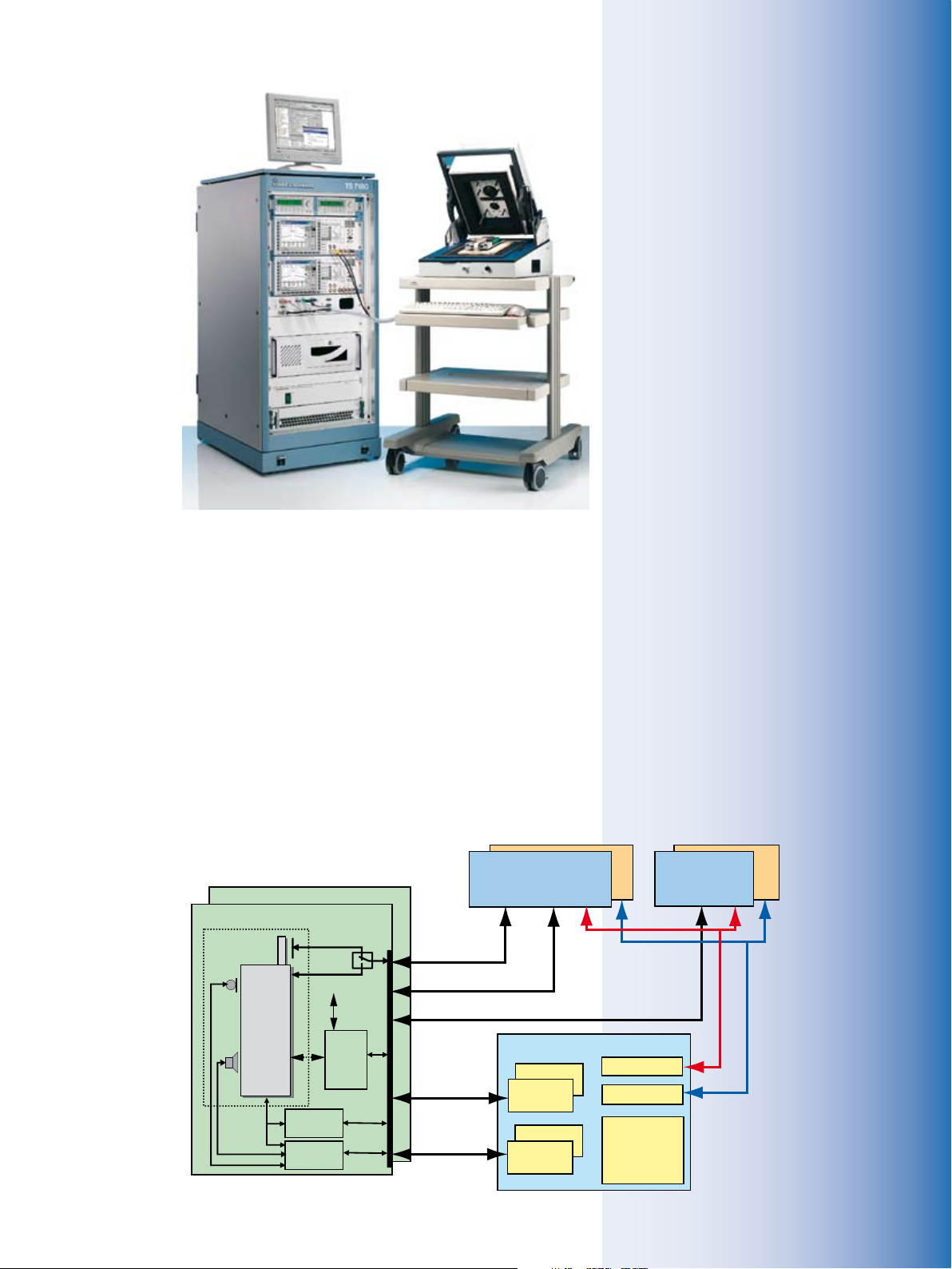
¸TS7180 description in brief
The ¸TS7180 test platform can test
two mobile phones simultaneously. It
essentially consists of two Radio Communication Testers ¸CMU200, two
Dual-Channel Analyzers/Power Supplies
¸NGM02, two Shielded RF Test Fixtures ¸TS7110 for holding the DUT,
and an industrial PC. The modular RF
Test Fixture ¸TS7110 can be expanded from a bed-of-nails PCB test fixture
up to a fully configured test fixture for
final testing, including an antenna for RF
tests, a loudspeaker and microphone for
acoustic tests, a camera for LC display
Shielded test chamber 2 final test
Shielded test chamber 1 final test
Air coupling
Wire coupling
Fixture
control
Level
converter
Audio
amplifier
Bottom
connector
DUT
Industrial PC
COM 1
Keypad
Mouse
Graphics
LAN
Printer, HD
DUT control
GPIB #1
GPIB #2
Radio Communication Tester 1
R&S CMU200
RF In/Out
Audio In/Out
Power supply 1
Dual-channel
battery/charger
GPIB #2
GPIB #1
Fixture control
COM 2
USB 1
USB 2
USB
DIO
interface
Audio
RF
Battery/charger/sense
¸TS7180:
example of a
two-channel
system with one
¸TS 7110
fixture.
Software concept in brief
¸TS 7180/7110 features in brief
High throughput by parallel testing of
◆
mobile phones
One system for functional board test,
◆
phone calibration and final test
One system for all major mobile phone
◆
standards
Easy expansion to 3rd generation tech-
◆
nologies
Ready-to-run Rohde & Schwarz GTSL test
◆
library for immediate use or customization
Modular and versatile hardware/software
◆
platform
Reduced costs due to generic concept
◆
Swap kit
◆
For detailed information, see separate data
sheets:
¸TS 7110 (PD 0757.7723)
¸TS 7180 (PD 0757.7469)
Software platform based on
◆
LabWindows/CVI and TestStand
from National Instruments
GTSL includes ready-to-run test cases
◆
for the standards supported by the
¸CMU200
Functional test sequences for RF test,
◆
calibration, signaling test, audio and
acoustic test of mobile phones are
supported
Block diagram
for a two-channel
configuration of
the ¸TS 7180.
¸CMU200 Universal Radio Communication Tester 7
Transparent and open library can be
◆
expanded by the user
Operator interface (GTOP) and test
◆
cases can be easily customized
Parallel test of multiple mobile
◆
phones is fully supported
GTSL supports multithreading and
◆
instrument sharing if needed
Test development time is reduced by
◆
as much as 80 %

8 ¸CMU200 Universal Radio Communication Tester
Ready for today’s networks …
GSM today
Since its introduction in the early nineties, the GSM system has won acceptance and undergone an evolution that
no one could have foreseen.
Currently, the following GSM systems
are deployed in support of numerous applications worldwide:
GSM400
◆
GSM850
◆
GSM900 including
◆
P-GSM (primary GSM)
–
E-GSM (extended GSM)
–
R-GSM (railway GSM)
–
GSM1800 (DCS)
◆
GSM1900 (PCS)
◆
Whether the application is in production,
service or development, the flexible concept of the ¸CMU200 can handle
practically all requirements: from basic
RF signal generation, frequency, power
and spectrum analyzer measurements
for the alignment of modules in production or development, to full GSM-specific
signaling in any of the above-mentioned
bands, as well as module tests on frequencies anywhere in the range from
10 MHz to 2.7 GHz.
Signaling mode
The ¸CMU200 simulates a GSM
base station RF interface, providing the
signaling flexibility necessary to test the
performance of a mobile phone under
the influence of different signaling parameters. These parameters are normally
set by the network operator but can be
reproduced by the ¸CMU200 for
test purposes. The instrument supports
the latest fast location update and direct
paging features.
Reduced signaling synchronized mode
The ¸CMU200 provides the same
functionality as in the signaling mode
but discards any signaling response from
the mobile phone connected. This mode
of operation enables testing of modules
that only have layer 1 capabilities as well
as very fast RF testing in production environments. It can also skip the location
update procedure in order to save time.
Non-signaling mode
This mode is used to generate a signal with GSM-specific midambles and
modulation in the entire frequency range
from 10 MHz to 2.7 GHz. The analyzer offers the same flexibility for GSM-specific
transmitter measurements such as
Modulation analysis
◆
Average and peak burst power
◆
Power versus time, power versus slot,
◆
power versus frame
Spectrum due to switching/modula-
◆
tion
GSM development
As a tool for GSM development engineers, the ¸CMU200 is an unsurpassed solution. The RF interface provides four input and output connectors
offering a wide range of signal levels
for the generation and analysis of RF
signals. Input-only connectors, as well
as combined input/output connectors,
can analyze mobile phones or modules
with a sensitivity down to –80 dBm and
up to +47 dBm for the power meter. RF
signals can be generated with levels
from –130 dBm up to +13 dBm, depending on the selected connector.
All measurement tolerances are set by
default in line with the 3GPP TS 51.010
and 3GPP TS 45.005 recommendations but
may be altered to suit individual needs.
Production of mobile phones
Production is a process that calls for cost
effectiveness. The ¸CMU200 concept is optimized for IEC/IEEE bus speed,
measurement accuracy and reproducibility as well as cost of ownership. Owing
to multitasking capability and parallel
measurements, previously unobtainable
test times can be achieved.
The flexible ¸CMU200 hardware
concept allows the latest DSP technologies to be used in measurements, e.g.
to speed up transmitter measurements
(spectrum due to switching/modulation)
to the extent that measurements virtually in realtime are possible.
The ability to process BER data and perform transmitter measurements at the
same time allows phase/frequency error,
power versus time and average power
(PCL accuracy) to be measured during
the time-consuming receiver test.
The accuracy and reproducibility ensure
correct and stable measurement results
and thus contribute to the quality and
reliability of the end product.
GSM speech evolution – AMR
Maintaining good voice quality even under extremely poor transmission conditions is now possible with the innovative
adaptive multirate (AMR) voice coding
algorithm, which opens up new possibilities for GSM. The new algorithm allows
voice quality to be gradually reduced
in favor of improved error correction by

The GSM-specific non-signaling test
provides generation and analysis of
RF signals (GMSK or 8PSK modu-
lated) for testing RX/TX modules or
mobile phones in service mode.
For an AMR full-rate or AMR half-
rate link, a rate set of up to four
combinations of voice and channel
codings (codecs) can be selected
from the eight full-rate and the six
half-rate codecs. During a call, it is
possible to switch between the rates
of the rate set.
The overview menu provides fast
comprehensive information on the
mobile phone‘s RF performance; the
hotkeys at the bottom of the screen
provide immediate access to specific
and detailed GSM measurements.
¸CMU200 Universal Radio Communication Tester 9
10 ¸CMU200 Universal Radio Communication Tester
dynamically adapting the data rate. Interruptions of voice transmission can
thus be avoided by allowing a barely
perceptible reduction in audio quality.
The ¸CMU200 provides all eight
combinations of voice and channel coding (codecs) for full-rate and six combinations for half-rate transmission. For
call setup, a set of four rates (codecs) is
selected from the eight full-rate and the
six half-rate codecs. Then additional test
parameters (thresholds) are selected for
the mobile phone. Dynamic switchover
between the selected rates is effected by
AMR inband signaling. In the uplink, the
mobile phone informs the base station
about the quality of the established link
and proposes the optimal rate for the selected rate set to the base station.
GSM data evolution – 2.5G
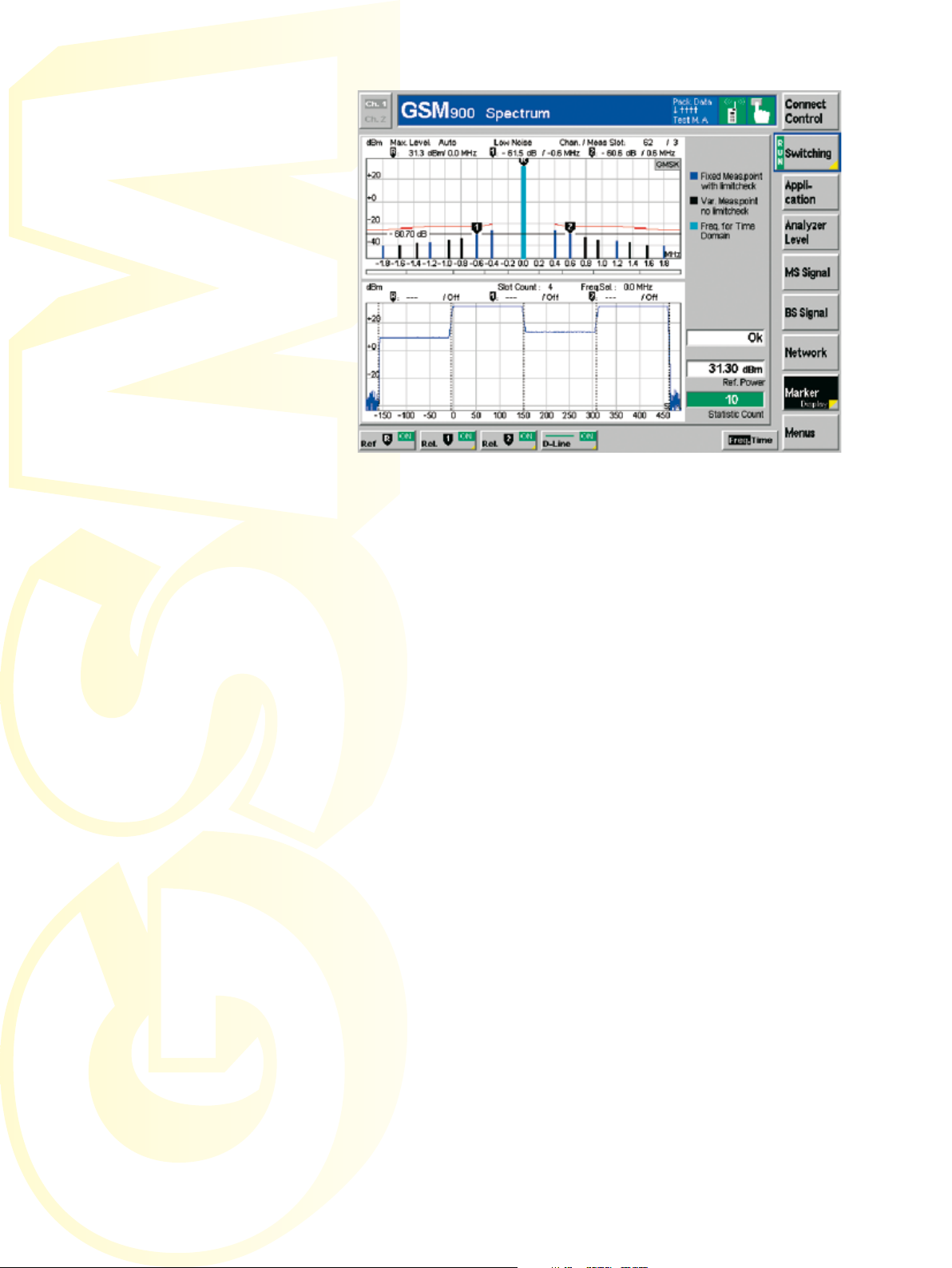
The newly designed spectrum application allows the simultaneous measurement of spectra due to
switching and modulation in realtime. Moreover, the user can select a frequency offset (spectral
line) by means of a marker and display it in the time domain. Transient characteristics in spectrum-due-to-switching measurements can thus be shown as a function of time.
The amount of data traffic in GSM networks is growing rapidly. Multislot applications such as HSCSD, GPRS and
the innovative 8PSK modulation scheme
EDGE are needed to support the increase
in data traffic. The ¸CMU200 platform is not only able to handle today‘s
standards and systems but is also designed for the needs of tomorrow.
Multislot
In the future, mobile phones will be able
to use several timeslots simultaneously
for data transmission and reception to
further increase the data rate. The simultaneous transmission and reception
of several timeslots (multislot) is the
main technological challenge for circuitswitched and packet-switched applications. The following expansions of the
GSM single-slot measurements enable
maximum flexibility in development, and,
with reduced measurement times, maximum throughput in production.
◆
in the downlink (DL). The ¸CMU
generates up to eight timeslots per
frame in the downlink; each timeslot
can be assigned a separate level.
The excellent level stability of the
¸CMU200 generator is not impaired by multislot transmission using
different levels, and allows highly accurate receiver sensitivity measurements (BER/BLER)
Transmitter and receiver measure-
◆
ments are possible on every timeslot
used. The new multislot concept allows independent measurements on
any timeslot (TS 0 to 7) and thus covers the current and future multislot
combinations without restrictions
The ¸CMU200 combines high
◆
flexibility with great operating convenience. Based on the multislot capability information from the mobile
phone, the ¸CMU200 selects the
maximum possible number of timeslots for a specific application and,
when changing between transmitter and receiver tests, automatically
adapts the timeslot allocation
Power-versus-time measurement
◆Individual levels for all timeslots used
(graphical display) for up to four timeslots in the uplink (UL). The templates
of this application are evaluated independently for each timeslot – in line
with standards and recommendations. Both GMSK- and 8PSK-modulated signals are recognized, and the
templates of the relevant timeslot,
depending on the modulation scheme
used, are set in realtime
Multislot measurements are required for
HSCSD technologies as well as for GPRS
and EGPRS.

The power-versus-time multislot application can graphically display up to 4 adjacent timeslots,
automatically detect GMSK- and 8PSK-modulated signals and activate the associated templates
in realtime. A new zoom function allows full-screen display of up to four slots. Moreover, the user
can zoom in anywhere along the time or power axis.
8PSK modulation – EDGE
In addition to multislot, a further step
toward increasing the mobile radio
data rate is 8PSK. By using the available GSM frame structure, the gross
data rate is three times that obtained
with GMSK. Error vector magnitude and
magnitude error have been added to
the range of modulation measurements.
New templates for power-versus-time
measurements ensure compliance with
the specifications, as do the modified
tolerance for spectrum measurements.
As with all measurements provided by
the ¸CMU200, special attention has
been given to achieving maximum mea-
GPRS/EGPRS
With newer, future-oriented methods
of packet data transmission, the radio
resources of existing GSM mobile radio
networks can be utilized efficiently for
data services. As with circuit-switched
services, GPRS will also use a combination of several timeslots (multislots)
and higher-level modulation in the
form of 8PSK (EGPRS) to increase the
data rate. The introduction of packetoriented transmission and the associated temporary assignment of radio resources require new test concepts. The
¸CMU200 provides the following
test modes:
surement accuracy and speed for EDGE.
3GPP test mode A (GPRS/EGPRS)
In this mode, the mobile phone continuously transmits the associated UL timeslots. The ¸CMU200 can carry out
all TX multislot measurements available,
such as the power ramp measurement of
up to four adjacent timeslots simultaneously, or modulation and spectrum measurements.
Selecting the coding scheme determines
whether the mobile phone is to transmit
GMSK- or 8PSK-modulated data. With GPRS/
EGPRS, transmission resources are usually
allocated temporarily. The uplink state flag
(USF) transmitted in the downlink informs
the mobile phone that uplink resources have
been allocated for the next block and that
these resources have to be used. Correct decoding of the highly protected USF sequence
is an essential prerequisite for the “dynamic
allocation“ and “extended dynamic allocation“ modes to work properly, and is verified by the ¸CMU200 by means of the
USF BLER test (test modes A and B). Various
routines, e.g. USF BLER and false USF detection, are available.
3GPP test mode B (GPRS/EGPRS)
This mode creates a loopback in the mobile
phone so that the mobile phone retransmits
data blocks received from the ¸CMU200.
To achieve maximum measurement speed,
the test mode does not employ the backward error correction function used in packet data transmission, which enables the acknowledgement-based (acknowledged/not
acknowledged) retransmission of erroneous
data blocks. The transmitter and the receiver are active at the same time. The mobile
phone returns the received data blocks to
the ¸CMU200 unchanged, comparable
to the loopback mode in circuit-switched operation. The data is looped back after channel coding, which means that the mobile
phone‘s coder and decoder functions are
tested as well.
In addition to the measurements available
in the 3GPP test mode A, test mode B enables very fast receiver test, bit error ratio
and Rohde & Schwarz-proprietary block error
ratio measurements in parallel to transmitter
tests (BER/DBLER)
¸CMU200 Universal Radio Communication Tester 11

12 ¸CMU200 Universal Radio Communication Tester
Fast production test mode for
test modes A, B and (E)GPRS
loop (GPRS/(E)GPRS)
3GPP EGPRS symmetrical and
non-symmetrical loopback mode
(EGPRS only)
Unlike in test mode B, the data blocks
are looped back before they undergo
channel coding, i.e. the coders are bypassed in favor of increased measurement speed. In the symmetrical (E)GPRS
loopback mode, 8PSK-modulated data
blocks are received in the downlink and
returned unchanged in the uplink. In
the non-symmetrical mode, 8PSK data
blocks are received in the downlink and
returned in the uplink as GMSK-modulated data spread over the next three
data blocks. Similar to test mode B, the
(E)GPRS loopback mode allows simultaneous transmitter and receiver tests
to be performed at an even higher data
throughput.
3GPP BLER measurements –
acknowledge mode (GPRS/(E)GPRS)
The BLER measurement mode employs
GPRS/(E)GPRS backward error correction. The ¸CMU200 sends data
blocks in allocated timeslots in the
downlink. The mobile phone checks the
data blocks for errors (CRC check) and,
instead of returning the data blocks, returns only the block acknowledgements
in the uplink. The mobile phone transmitter is thus only temporarily active
for sending uplink acknowledgements,
which means that transmitter measurements are possible only to a limited extent in the BLER mode.
For R&D requirements, the BLER menu
opens up a wide range of options to determine receiver characteristics even
beyond the scope of the 3GPP test scenarios. The ¸CMU200 furnishes an
average result over all timeslots used,
as well as the BLER and the actual data
throughput for each timeslot. The downlink transmitter level can be varied separately for each timeslot and is displayed
as an important test parameter together
with the data throughput and the resulting BLER. The (E)GPRS BLER measurement is based on a new retransmission
algorithm referred to as “incremental
redundancy“.
Incremental redundancy means that
errored blocks are retransmitted using
a different puncturing scheme. The
¸CMU200 can cycle through the
puncturing schemes as specified by the
3GPP standard, or start with a specific
puncturing scheme, or use the same
puncturing scheme throughout (incremental redundancy OFF).
Extremely fast adjustment and testing
of RF parameters during mobile phone
production is ensured by deactivating
the GPRS/(E)GPRS protocol stack. Without using all functions on the higher
protocol layer (RLC/MAC layer), the
¸CMU200 synchronizes the mobile
phone (camping), and the data channel
(PDCH) is then set up directly without
executing the time-consuming routines
of location update and GPRS/(E)GPRS
attach. Any signaling for reconfiguring
the test setup is likewise omitted. The
fast production test mode developed by
Rohde & Schwarz provides test conditions comparable to those defined for
the 3GPP test modes. The ¸CMU200
performs all transmitter and receiver
measurements described by 3GPP, but at
a considerably higher speed.

For GPRS/EGPRS, BLER measurements can be performed simultaneously on up to four downlink
timeslots. The actual data throughput, the BLER and the resulting data rate (RLC/MAC layer) are
displayed separately for each timeslot and as an average for all timeslots used. Furthermore an
incremental redundancy performance test is performed, and the channel quality is indicated.
GSM highlights of the
¸CMU200
Benchmark-breaking IEC/IEEE bus speed
due to
Optimized processing power and fast
◆
modulation spectrum measurement using
latest DSP generations
Statistical BER test based on confidence
◆
evaluation
High flexibility for R&D
Assignment on up to 8 UL and DL slots
◆
(TS 0 to 7)
TX/RX on any transmit slot
◆
Individual level generation on any DL slot
◆
used
3GPP packet data test mode supporting
◆
modes A, B and (E)GPRS loop
GPRS/(E)GPRS TBF reconfiguration during
◆
established link
GPRS/(E)GPRS intra-band handover
◆
In the 8PSK mode, the modulation analysis is subdivided. The error vector magnitude (EMV),
the magnitude error and the phase error can be displayed both numerically as shown above, or
graphically.
GMSK/8PSK measurements
Phase/frequency error, EVM, magnitude
◆
error, origin offset, I/Q imbalance GMSK
for I/Q modulator tuning
Power versus time
◆
On up to 4 UL slots
–
Normal/access
–
Peak power/average, power versus
–
frame, power versus slot
High-speed ACP measurement (switching
◆
and modulation measurement in parallel)
with additional time domain view
Timing error
◆
BER/DBLER, RBER/FER, FastBER
◆
BLER@4DL (GPRS/EGPRS)
Incremental redundancy support
◆
((E)GPRS)
Power versus PCL (on 3 or 7 channels)
◆
¸CMU200 Universal Radio Communication Tester 13

14 ¸CMU200 Universal Radio Communication Tester
WCDMA in the ¸CMU200
The need for higher data rates is the
consequence of an information-oriented society in the new millennium. The
enhancement of mobile devices takes
this need into account. Third-generation wireless communications pose new
challenges. Driven by ideas of the first
and second generation (SIM, global
roaming, CDMA technology, data services), WCDMA takes all fundamentals
to unprecedented levels and adds new
application fields as well as application-tailored data security. Derived from
Asian, American, and European ideas,
3G networks are the mobile solution
for future needs as well as the current
mainstream.
WCDMA FDD functionality
The tests provided by the ¸CMU200
are based on 3GPP/FDD Release 99 and
optional R5/R61) 2) WCDMA radio link
standards. Regular adaptations to new
releases and baselines are made as the
standard evolves; thus the ¸CMU200
today supports Release 5 as well as Release 6. Most of the measurements offered comply with the 3GPP specification
TS 34.121, chapter 5 (transmitter characteristics), chapter 6 (receiver characteristics), chapter 7 (performance tests), and
chapter 9 (performance requirements for
HSDPA)1) and chapter 10 (Performance
Requirements for HSUPA)2).
The ¸CMU200 can be equipped
with an FDD transmitter tester, an additional FDD generator, and FDD signaling hardware. Depending on the application, only the first or the first two
might be needed, allowing T&M budgets
to be optimized. The three units allow
the ¸CMU200 to be configured for
non-signaling TX, TX/RX or signaling TX/
1)
More ab out the HSDPA c apabilities in the f ollowing
sect ion.
2)
More ab out the HSUPA c apabilities in the f ollowing
sect ion.
RX measurements and functional testing on the UE (user equipment) in line
with the 3GPP specification. Due to the
highly user-friendly menu concept, the
¸CMU200 provides quick access to
all required measurements and optimizes
the handling and thus the efficiency of
complex measurement tasks with appropriate status messages and built-in
statistical functions. Different WCDMA/
FDD handover capabilities such as interfrequency and inter-band handover are
available in the ¸CMU200 WCDMA
solution. Moreover, handover to other
cellular networks such as GSM, i.e. interRAT handovers – blind or in compressed
mode – are implemented.
Non-signaling mode
The non-signaling mode is for generating
and analyzing WCDMA (3GPP/FDD)
signals in the full frequency range
of the ¸CMU200 base unit. The
¸CMU200 provides WCDMA-specific
TX measurements on signals with up to
six DPDCHs such as:
ACLR (adjacent channel leakage
◆
power ratio): two measurement
modes, filter (bargraph) and FFT
(cont. spectrum) method; absolute or
relative readout
OBW (occupied bandwidth)
◆
SEM (spectrum emission mask)
◆
CDP (code domain power):
◆
CDP vs all codes, CDP vs DCH channels, RHO vs all codes, RHO vs DCH
channels; all measurements in relative
or absolute readout, CDP versus time
Modulation (for 3GPP or general
◆
QPSK): EVM (error vector magnitude),
magnitude error, phase error, frequency error, I/Q offset, I/Q imbalance,
peak code domain error, RHO (waveform quality), transmit time error,
I/Q constellation/vector/eye diagram
Power: MAX, MIN, OFF (UE test
◆
mode)
Power versus slot, inner loop power
◆
Phase discontinuity
◆
The non-signaling mode allows tests of
all essential RF parameters of the connected UE, where autoranging for the
received UE signal is also applied. The
measurements are performed in unsynchronized mode. No call is set up
to evaluate UE performance using this
mode. No 3GPP FDD generator option is
needed. The capability to use different
3G dedicated triggers such as signaling trigger, IF, TPC, frame or slot trigger,
HSDPCCH etc, together with the flexible
trigger settings such as delay and delay
offset make this an interesting tool for
R & D applications where a protocol stack
is not available.
Reduced signaling
synchronized mode
This mode requires the 3GPP FDD generator option to be installed on top of the
transmitter tester. This generator for the
¸CMU200 provides all necessary forward link channels and 3GPP-conforming AWGN and orthogonal noise signals.
16 channels with OCNS can be added
and their power levels changed.
The generated channels and available
functions include the following:
P-CPICH/P-SCH/S-SCH/P-CCPCH/
◆
S-CPICH/PICH/DPCCH/DPDCH
Flexible adjustments of physical pa-
◆
rameters such as power, code, etc
for physical channels, including the
generation of data (pseudo noise sequences, and fixed data patterns)
TPC profiles (three predefined, one
◆
user-defined setting, seven user-selectable, five definable TPC setups)
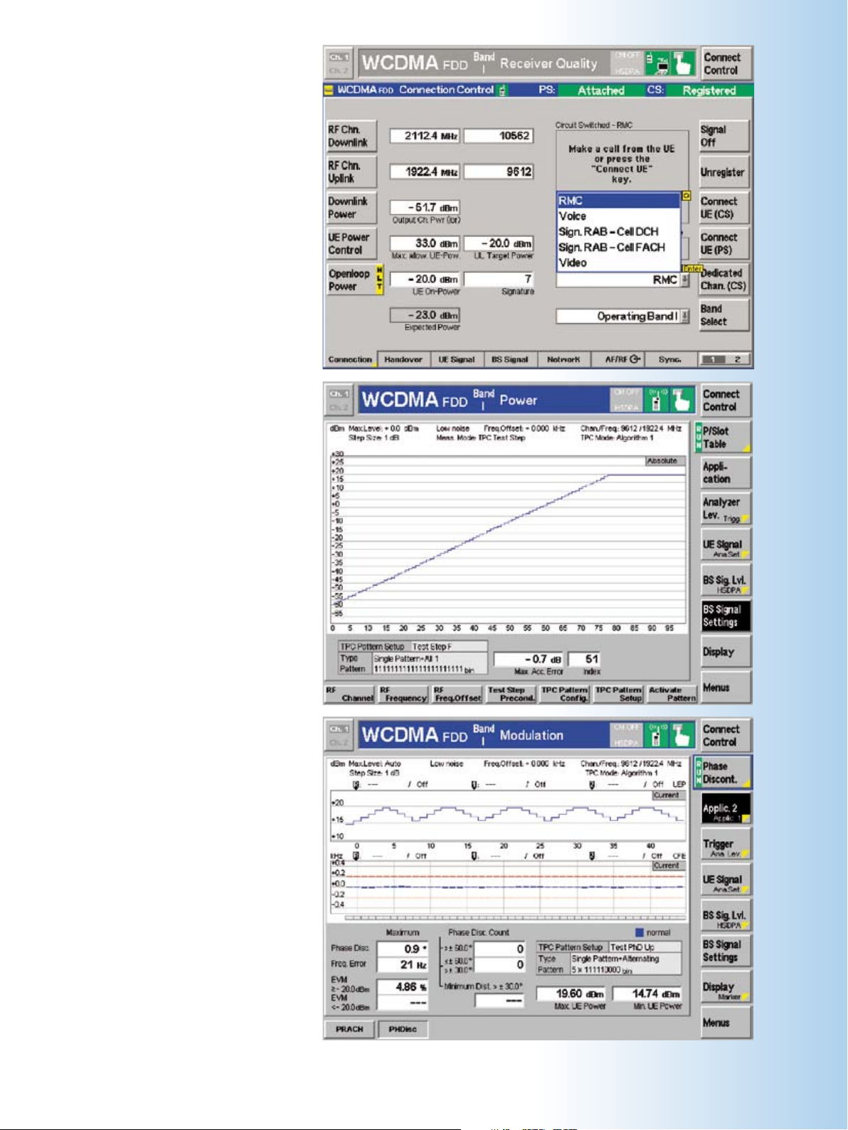
In the connection folder of the con-
nection control menu, all relevant
¸CMU200 connection set-
tings are displayed together with
the reported UE capabilities. The
main control buttons to initiate and
release different connection types
are located here.
This screenshot shows a typical UE
output power response to the TPC
patterns. The power vs slot mea-
surement can be used with the pat-
terns A through H, a combination
of algorithms 1 and 2, and different
step sizes. Here, pattern F is used.
The inner loop measurement can be
displayed as absolute and relative
graphics or as a numeric power ver-
sus slot table.
In the phase discontinuity measure-
ment, the upper diagram shows the
measured UE power in up to 46 con-
secutive slots corresponding to the
last TPC pattern sent to the UE.
The lower diagram shows the phase
discontinuity in the measured slots.
¸CMU200 Universal Radio Communication Tester 15

16 ¸CMU200 Universal Radio Communication Tester
WCDMA in the ¸CMU200
OCNS (16 orthogonal channels)
◆
OCNS/Rel. 99 and OCNS/Rel. 5
AWGN
◆
The ¸CMU200 generator can also
provide non-channel-coded data on
the physical layer and allow slot formats from 0 through 16 to be selected.
Synchronization of the UE (but still no
call setup) is mandatory for RX evaluation, synchronized TX measurements,
and additional TX measurements such as
inner-loop power control with TPC commands:
TPC stepping measurement
◆
(UE receives TPC commands from the
¸CMU200 generator)
Receiver quality: BER, BLER, and
◆
DBLER (two modes, UE-assisted
evaluation, or RF loopback (realtime
receiver option needed))
Phase discontinuity measurement
◆
Using the ¸ABFS baseband fading
simulator and the ¸CMU200 with
optional IQ/IF interface, conditions of
fading may be simulated and the results
evaluated with the ¸CMU200. In
contrast to RF fading, a baseband fading
scenario makes it possible to maintain
the extremely high downlink accuracy
provided by the ¸CMU200 3GPP
FDD generator. In addition, basebandfaded testing usually comes at a much
lower cost than an RF fading solution.
All fading tests are possible in synchronized or signaling mode. The optional
IQ/IF interface can also be used for baseband testing when no RF section of the
UE is available in R&D.
The ACLR menu shows all adjacent-channel-related information in graphical as well as in scalar
numeric form. Since the ACLR FFT and OBW measurement methods are closely related, results
for occupied bandwidth are displayed simultaneously. The scalar display excluding the center
channel (0 MHz) may be switched to absolute readout as well.
FDD signaling mode
Signaling tests are tests in an environment closer to a true live network. 3GPP
currently specifies eleven different operating bands for FDD (bands 1 through
11). All eleven bands are optionally supported by the ¸CMU200.
The measurements offered are largely the
same as performed in synchronized mode.
In signaling mode, the ¸CMU200
simulates one WCDMA base-station RF
interface including the signaling protocol so that an FDD UE can be tested with
regard to various signaling parameters.
All necessary network and Node B (base
station) parameters such as control and
data channel configurations can be set.
In addition to the non-signaling tests, the
¸CMU200 provides features such as:
Dynamic setting of signaling
◆
parameters
RRC connection setup
◆
Readout of UE capabilities
◆
Authentication and security (integrity)
◆
Call setup (MOC, MTC)
◆
Call release (NIR, MIR)
◆
Measurements from non-signaling
◆
section
Open-loop power control (on/off time
◆
mask for RACH preambles)
Modulation quality measurements
◆
during the random access procedure
(PRACH preambles)
Phase discontinuity in line with
◆
3GPP TS 31.121 chapter 5.3.13
Inner-loop power control (traffic
◆
power commands, TPC patterns A
to H)
Test mode/test loop activation com-
◆
mand (test loop mode 1, transparent,
and test loop mode 2 with and without uplink CRC)
BTFD (blind transport format detec-
◆
tion) with false transmit format detection ratio (FDR) and transport format
indicator (UL TFCI)

The UE reports for the current and neighbor FDD cell (can be obtained from an existing FDD
cell on the air, for example) and from a neighbor GSM cell can be requested by activating the
compressed mode patterns. Four predefined compressed mode patterns can be combined. The
¸CMU200 also provides full flexibility with user-defined patterns as well as all 3GPP defined
compressed mode patterns.
Receiver quality: BER, BLER, and
◆
DBLER (RF loopback)
Readout of UE measurement reports
◆
on current and neighbor cell (UTRA/
GSM) (with activated compressed
mode (CM))
Several possibilities for handovers:
◆
from WCDMA to GSM (blind and
compressed mode), and back from
GSM to WCDMA (blind handover),
including neighbor cell measurement
The measurements can be performed
on different radio access bearers (RAB)
such as:
WB-AMR (optional) at 23.85 kbit/s,
◆
23.05 kbit/s, 19.85 kbit/s, 18.25 kbit/s,
15.85 kbit/s, 14.25 kbit/s,12.65 kbit/s,
8.85 kbit/s, 6.60 kbit/s (codec set A to
I, M) with selectable audio loopback
RMC at 12.2 kbit/s, 64 kbit/s,
◆
144 kbit/s, 384 kbit/s
Asymetric RMC at
◆
UL/144 kbit/s DL/64 kbit/s
UL/384 kbit/s DL/64 kbit/s
UL/384 kbit/s DL/144 kbit/s
BTFD (blind transport format detection
◆
12.2 kbit/s RMC in combination with
◆
HSDPA and HSUPA (optional)
Video call in loopback mode at
◆
64 kbit/s fixed data rate in UL, DL
SRB at 1.7 kbit/s, 2.5 kbit/s,
◆
3.4 kbit/s, and 13.6 kbit/s
AMR at 12.2 kbit/s, 10.2 kbit/s,
◆
7.95 kbit/s, 7.4 kbit/s, 6.7 kbit/s,
5.9 kbit/s, 5.15 kbit/s, 4.75 kbit/s
(codec set A to H, M) with selectable
audio loopback
Packet-switched connection at
◆
fixed data rate of UL/64 kbit/s and
DL/384 kbit/s or 64 kbit/s UL and DL,
or 384 kbit/s UL and DL, 64 kbit/s
and 384 kbit/s in combination with
HSDPA and HSUPA (optional)
An optional AMR speech codec for
WCDMA that supports the above-listed
data rates is also available. It allows audio measurements to be performed with
the ¸CMU200 audio board (option)
or on an external audio analyzer, e.g. the
¸UPL16.
The high flexibility of the signaling
stack allows various parameters in the
¸CMU200 MMI to be changed or
different Node B configurations to be
simulated via remote control.
Quality assurance
Due to its high measurement repeatability and accuracy, the ¸CMU200
is the right choice to help ensure a consistently high level of quality. WCDMA specific measurements such as BER/
BLER and EVM, plus the full implementation of complementary (i.e. ACLR
and OBW) measurements provide an
excellent test platform for high-quality
products. Unrivaled AF/audio and RF/
)
fading performance allows test setups at
a low price, with compact size and high
test depth.
¸CMU200 Universal Radio Communication Tester 17

18 ¸CMU200 Universal Radio Communication Tester
WCDMA in the ¸CMU200
WCDMA development
The well-structured, user-friendly menu
design and the clear-cut screen layout
provide quick access to all features and
ensures trouble-free monitoring of the
device under test (DUT). The tester can
be switched between 3GPP and general
QPSK modes to increase the usability
with DUTs under development. For analysis of the signaling messages between
the UE and the ¸CMU200, an optional message analyzer is available.
Production of mobile phones
The production of mobile phones requires time-efficient and cost-effective measurements that simultaneously
ensure both high throughput and high
yield. Owing to market-leading accuracy
and the unique IEC/IEEE bus concept of
the ¸CMU200, these two goals can
be easily achieved in production environments.
Repair applications (manufacturing and service centers)
With its outstanding versatility, the
¸CMU200 is also a suitable tool
for mobile phone troubleshooting. Four
configurable RF ports and a built-in RF
connector switch matrix (standard unit)
are provided to enable flexible signal
level ranges and switching. Since each
¸CMU200 measurement menu allows an independent setting for the
input and output ports, a phone fixture
and spectrum analyzer probe can
remain permanently connected to the
¸CMU200.
After the software has been ported to the mobile phone, users often want to record protocols to optimize internal processes or to perform an error analysis that may be necessary. The ¸CMU-Z46 message analyzer and recorder option allows all universal terrestrial radio access network (UTRAN) protocol layers to be recorded, which can then be used for more detailed analysis. When installed on an external PC and communicated to the ¸CMU200
via an Ethernet connection, this powerful tool permits in-depth analyses, including transport layer analyses.

This measurement shows the receiver sensitivity measurement on a UE at –110 dBm P-CPICH in
test-loop mode 2. In addition to the minimum DL power condition, the compressed mode can be
selected to see if the same sensitivity is maintained with compressed mode. The ¸CMU200
also provides a ”lost transport blocks” counter for easier troubleshooting.
Switching standards
Multimode UE applications are possible
using the handover capabilities of the
Fast switching between 3GPP FDD and
any of the other numerous standards
supported by the ¸CMU200 is a
standard feature of the instrument and
can be achieved by simply pressing a
¸CMU200 such as blind and com-
pressed mode handover to GSM as well
as blind handover or handover including
inter-RAT neighbor cell measurement
from GSM back to WCDMA.
button.
Versatile production test layouts are possible and true multimode test bays that
utilize the flexibility and throughput of
the ¸CMU200 are no longer a concept of the future.
WCDMA highlights of the
¸CMU200
Benchmark-breaking ICE/IEEE bus speed
◆
(see highlights of base unit)
Combined measurements, many different
◆
measurement modes
Multiband/multimode testing
◆
Powerful signaling capabilities available:
◆
MOC, MTC, MIR, NIR, inter-frequency
handover, inter-band handover, inter-RAT
handover
Display of UE capabilities
◆
Large selection of radio access bearers
◆
(RABs) with various data rates including
video call in loopback mode
Up to 384 kbit/s reference measurement
◆
channels (symmetrical and asymmetrical)
3GPP-conforming generation of OCNS
◆
(orthogonal channel noise simulation)
and AWGN
Separate and highly accurate level set-
◆
ting for individual DL code channels
Simple voice test using AB/echo by
◆
tester; dedicated audio tests available
(option)
User-defined settings of RF-relevant
◆
signaling parameters
ON/OFF time mask for open-loop power
◆
measurements including the system info
settings
Power vs slot menu for realtime measure-
◆
ment of RMS UE transmit power in up to
100 consecutive slots
3G dedicated trigger options such as IF
◆
power, signaling, slot, frame, preamble,
PRACH message part, TPC, compressed
mode, and change of TFC trigger
External message analyzer for reading
◆
signaling message log files (option)
Simple interactive operation in manual
◆
MMI
Configuration of compressed mode for
◆
neighbor cell reports
Handover and BER/BLER procedures
◆
during compressed mode
¸CMU200 Universal Radio Communication Tester 19

Base station
DUT
Downlink DPCH
Shared control channel (HS-SCCH) 1
Shared control channel (HS-SCCH) 2
Shared control channel (HS-SCCH) 3
Shared control channel (HS-SCCH) 4
Uplink DPCH
HS-DPCCH
Data
Modulation/
code assignment
FEC
HS-PDSCH (15 channels)
ACK / NACK,
channel quality
indicator
20 ¸CMU200 Universal Radio Communication Tester
WCDMA evolution – high speed downlink packet access
High speed downlink packet
access (HSDPA)
Fast, high-quality data services are already possible with WCDMA FDD Rel.
99 (frequency division duplex). As an
extension of this functionality, 3GPP
Rel. 5 (HSDPA) increases the data rate
up to 14 Mbit/s by implementing new
data transfer techniques. The increased
data rate is made possible for two main
reasons: Both communicating entities
(Node B and UE) implement complex
data transfer principles in layer 1, and,
even more important, up to 15 new
physical channels (HS-DSCHs) have
been introduced in the downlink signal. The ¸CMU200 takes part in this
evolutionary trend by offering the software options for HSDPA in the signaling
and non-signaling modes. All you need
to do is install the key codes – no extra
hardware is needed. The only requirement for the HSDPA software option is
existing WCDMA functionality in the
¸CMU200.
HSDPA functionality
The HSDPA software options enable
the ¸CMU200 to generate up to
four HS-SCCHs and up to 15 HS-DSCHs
in the downlink signal. Thus, the
¸CMU200 can handle all HSDPA
categories 1 through 12. Furthermore,
the ¸CMU200 hardware already
supports HSUPA.
3)
More ab out the HSUPA c apabiliti es in the follo wing
sect ion.
3)
Channel structure of the physical channels with HSDPA.
Configuring the HSDPA channels
The ¸CMU200 downlink signal can
be configured in various ways, depend-
ing on the test purpose. This yields
maximum flexibility. Each of the four
HS-SCCH can be configured in power
or channelization code, or they can be
disabled. The HS-DSCH can also be
changed with respect to power, chan-
nelization code, and data pattern, and it
can be configured in three ways:
In accordance with the fixed refer-
◆
ence
channels (H sets). You can select
any of the 6 fixed reference channel
configurations defined by 3GPP that
use QPSK and 16QAM modulation
In
accordance
◆
table. Here, it is possible to use either a setting that corresponds to
a fixed CQI value (1 to 30) or automatically change the setting between
the corresponding parameters for a
minimum and maximum CQI value in
every TTI. You can also configure the
¸CMU200 downlink signal in
cordance
uplink signal (follow UL CQI mode)
with the CQI mapping
with the received CQI in the
ac-
User-defined configuration. Any of
◆
the following parameters can be adjusted individually: configuration of
the downlink (HS-DSCH) channels including TTI distance, number of HARQ
processes (1 to 8), transport block
size, number of HS-DSCHs, modulation, redundancy versions (0 to 7), etc.
Non-signaling and signaling
mode
Since HSDPA is primarily implemented
in layer 1, interaction can already be
provided between the UE and the tester
in the non-signaling mode. It is e.g. possible in non-signaling already that the
downlink signals (HS-DSCH) can be configured in accordance with the responses in the uplink signal HS-DPCCH (CQI,
ACKs, and NACKs) (follow UL CQI mode).
All the described functionalities in the
non-signaling mode are also provided
in the signaling mode. This includes the
above configuration and scheduling possibilities for the HSDPA channels.

This screenshot shows the ACK
report menu, which counts the
ACKs, NACKs, and DTXs for a
specific HARQ process or for all
HARQ processes. The throughput is
calculated from the number of ACKs
and the size of the transport blocks
transmitted.
The HS-DPCCH logging application
of the receiver quality measurement
provides the ACK/NACK messages
and reported CQI values that the
UE returns in a sequence of 120
consecutive HS-DPCCH subframes
(24 WCDMA frames).
This screenshot shows the reporting
of the CQI and testing for two cases:
whether more than 90 % of the re-
ported CQIs (except DTX) are in the
interval [median CQI – 2, median
CQI + 2], and whether the HSPDSCH
BLER on the median CQI is less than
or greater than 10 %. If the BLER on
the median CQI is < 10 %, the test is
repeated at (median CQI + 2);
otherwise, it is repeated at
(median CQI – 1). The BLER at
(median CQI + 2) must be >10 %,
and the BLER at (median CQI – 1)
must be <10 %. All this is imple-
mented as a “one button press” op-
eration for both cases, the above
described AWGN case, as well as
the also specified fading case.
¸CMU200 Universal Radio Communication Tester 21

22 ¸CMU200 Universal Radio Communication Tester
WCDMA evolution – high speed downlink packet access
New required measurements
In Rel. 99, the measurements that are
defined in chapter 5 (transmitter characteristics) of TS 34.121 are performed
using a 12.2 kbit/s reference measurement channel (RMC). This RMC defines one code channel on the I branch
(DPDCH) and one code channel on the
Q branch (DPCCH); both are continuously transmitted (except compressed
mode cases). With Rel. 5, there is an additional code channel for the uplink, the
HS-DPCCH. This code channel is on the
Q branch in the case of the 12.2 kbit/s
RMC and in the case of a signaling radio
bearer (SRB). This code channel is not
continuously transmitted, thus resulting in power changes that are not due
to inner-loop power control. Furthermore, the HS-DPCCH slot boundaries
are not necessarily aligned with the slot
boundaries of the DPCH, which means
that power transients may occur within
the inner-loop power control cycle. The
following properties of the HS-DPCCH
pose new challenges for UE transmitter
design:
The HS-DPCCH channel is switched
◆
on and off as a function of the dynamic time scheduling in the downlink, i.e. it is switched on or off each
time an HSDPA HARQ process is
active and scheduled
The slot boundaries of the channel
◆
are not synchronized with the timeslot pattern of the other uplink channels, but may be shifted by n × 256
chips relative to these
Transmitter measurements
The characteristics mentioned above
place new demands on the RF functionality of DUTs, which in turn calls for an
expansion of 3GPP TS34.121 RF test definitions. For example, an HS-DPCCH that is
The measurement diagram in code domain power measurement shows the DPCCH, the DPDCH,
and the HS-DPCCH. The measurement for the HS-DPCCH is divided into ten bars which represent
the powers of the ten HS-DPCCH symbols in the DPCH slot. Since the power of the HS-DPCCH
changes in line with its content, the timing offset between the HS-DPCCH and the DPCH can be
set to e.g. 50 % alignment. Thus, the power change between two slots transmitting different data
on the HS-DPCCH can be seen in the center of the DPCH slot. In this example, the first five symbols transmit ACKs or NACKs and the next five symbols contain CQIs.
out of tolerance may produce undesired
spectral components, which may affect
results both in modulation and spectral
(ACLR, SEM) measurements. The power
setting of the UE in limit ranges and transitional regions, for example at maximum
power, must correspond to a defined
nominal behavior. The ¸CMU200
can perform measurements (modulation,
spectrum, power, etc) using a time-variable HS-DPCCH trigger. By means of this
trigger, the additional RF component introduced by the HS-DPCCH uplink signal
can be included or omitted in measurements. The ¸CMU200 also supports
dedicated HSDPA transmitter measurements such as HS-DPCCH time mask,
EVM&PhD with HS-DPCCH and CDP versus time. Moreover, nominal beta and delta factors can be set on the ¸CMU200
for determining the code power of each
uplink code channel (DPCCH, DPDCH, and
HS-DPCCH).
Performance measurements
In addition to the transmitter characteristics, items defined in chapter 9
of 3GPP TS 34.121 related to performance tests are also covered in the
¸CMU200.
In the throughput measurement, the
¸CMU200 provides a receiver sensitivity measurement by counting the
ACKs, NACKs, and DTXs for a specific
HARQ process or for all HARQ processes. The throughput is calculated from
the number of ACKs and the size of the
transport blocks transmitted.
The ¸CMU200 can be configured in
such a manner that its downlink channels (HS-DSCH) correspond to the UE
category and to the CQI returned from
the UE (follow UL CQI mode).
ing on the feedback from the UE (ACKs,
NACKs, or DTXs), the ¸CMU200 can
send a different redundancy version of the
Depend-

HSDPA highlights of the
¸CMU200
Generation of up to four HS-SCCHs and
◆
up to 15 HS-DSCHs; configuration of
downlink HS-DSCHs in three different
ways:
3GPP-compliant fixed reference chan-
–
nels (H sets for QPSK or 16QAM)
In accordance with CQI mapping table
–
(1 to 30)
User-defined (providing full flexibility)
–
Force NACK function to test the perfor-
◆
mance of the UE by sending corrupted
blocks in the downlink
CQI interaction, in which the
◆
¸CMU200 generates the downlink
signal (HS-DSCH) in accordance with the
received uplink CQI (follow UL CQI)
Transmitter measurements by means
◆
The HSDPA measurement HS-DPCCH power control has been redefined in the 3GPP TS34.121/5.7A
specification to test the UL power variation due to the transmission of HS-DPCCH in combination with
inner loop power control. The new measurement in the ¸CMU200 allows the measurement of the
resulting power variation on the specified 17 (for ILP algorithm 1) or 14 (for ILP algorithm 2) dedicated
points on the 12 ms cycle. In the screenshot, the measurement for ILP algorithm 2 is shown.
data package, repeat the package with
the same redundancy version or continue
with a new package. During this scenario,
several measurements or reports are performed in parallel:
Percentage of transmissions that were
◆
transmitted or retransmitted (ACKs
and NACKs) or not answered at all
(discontinuous transmission, DTX)
Values are specified for the initial
◆
transmission as well as for the 1st
through 7th redundancy versions
Median of the CQI values reported by
◆
the UE
Throughput analysis
◆
Furthermore, chapter 9 of 3GPP TS 34.121
defines various tests for checking the reporting of CQI under AWGN propagation
conditions or under fading propagation
conditions. These measurements can be
performed in the ¸CMU200 as a “one
button press” operation by means of the
CQI reporting test. In the case of AWGN,
the measurement is performed in two
stages:
In the first stage, the ¸CMU200
checks whether more than 90 % of the
¸CMU200 Universal Radio Communication Tester 23
reported CQIs (except DTX) are in the interval (median CQI – 2, median CQI + 2) and
whether the BLER on HS-PDSCH at median CQI is greater than or less than 10 %.
If the BLER on the median CQI is < 10 %,
the test is repeated at (median CQI + 2);
otherwise, it is repeated at (median
CQI – 1). The BLER at (median CQI + 2)
must be >10 %, the BLER at (median
CQI – 1) must be <10 %. Similarly, the
CQI detection performance test under
conditions of fading is also implemented
as “one button press” operation in the
¸CMU200. The ¸CMU200 also
provides an additional HS-DPCCH logging
function. This function can be used to track
the HS-DPCCH in order to verify the response to the HARQ process scheduled by
the ¸CMU200. The logged HS-DPCCH
data may also be compared to logging
data from the UE. The log contains the
ACK/NACK and CQI data for 120 consecutive HS-DPCCH subframes on the MMI and
even more on the remote interface. The log
starts with subframe 0 of the next system
frame or can be triggered to start at a specific system frame number (SNF).
of the power, modulation, code domain
power, and spectrum measurements
in the presence of HSDPA (dedicated
HS-DPCCH trigger) in accordance with
chapter 5 of 3GPP TS 34.121
Receiver measurements by counting
◆
ACKs, NACKs, DTXs for a specific HARQ
process or all HARQ processes and data
throughput
CQI reporting test and HS-DPCCH log-
◆
ging tool
Configuration capabilities for the power
◆
offset parameters ∆ACK, ∆NACK,
and ∆CQI to control the power of the
HS-DPCCH
DPCH timing offset between the DPCH
◆
and the HS-DPCCH
Code domain power versus time mea-
◆
surement
Multiple RAB test mode types:
◆
12.2 kbit/s RMC + HSDPA (with closed
–
loop mode 1 RLC TM and loop mode 2)
3.4 kbit/s SRB RAB + HSDPA
–
12.2 kbit/s RMC + HSDPA in line with
–
3GPP TS34.108
12.2 kbit/s (+HSDPA) where the
–
HSDPA part is paged independently as
a PS RAB on top of RMC

DUT
Absolute grant channel (E-AGCH)
Relative grant channel (E-RGCH)
1 to 4 E-DPDCH
E-DPCCH
HARQ indicator channel (E-HICH)
Downlink DPCH
Uplink DPCH
Base station
Data
E-TFCI,
RSN,
happy bit
AG value
RG value
ACK/NACK
24 ¸CMU200 Universal Radio Communication Tester
WCDMA evolution – high-speed uplink packet access
High-speed uplink packet
access (HSUPA)
Following the increase of downlink data
rates with HSDPA, higher uplink data
rates are now in focus with HSUPA or
enhanced uplink (EUL). This extension to
WCDMA FDD Rel.99 is defined in 3GPP
Rel. 6 and increases the uplink data rate
from 384 kbps (WCDMA) to 5.76 Mbps.
To achieve this, data transfer technologies similar to those in HSDPA are used
in the uplink. This includes up to four
new physical data channels (E-DPDCHs)
and a new physical control channel
(E-DPCCH) in the uplink as well as complex data transfer principles in layer 1
such as the scheduling of the uplink
data rate by means of signaled grant
values. HSUPA also allows the dynamic
adaptation of the inter-TTI distance,
which means that data blocks can be
sent every 10 ms or, alternatively, every
2 ms.
Once again, the ¸CMU200 is setting
new standards by offering HSUPA as
a software option in the non-signaling
and signaling modes. All you need to
do is install the keycode – no extra
hardware is required. As is already the
case with HSDPA, the only requirement
for the HSUPA software option is existing WCDMA functionality in the
¸CMU200.
Channel structure of the physical channels with HSUPA
gain factors and reference E-TFCIs to the
UE, the uplink channels can be influenced.
In addition, all general RF measurements
such as power, modulation, spectrum,
and code domain power measurements
are updated in order to take the new uplink channels E-DPCCH and E-DPDCHs
into account. Moreover, specific HSUPA
measurements based on the performance measurement requirements in
3GPP TS 34.121 chapter 10 are implemented, and the content of the control
channel sent by the UE (E-DPCCH) can
be logged in detail. Plus, throughput
measurements on the physical layer and
on the RLC layer are also possible with
the ¸CMU200.
according to predefined patterns. These
grant values can be sent to the UE continuously (absolute grant update) or just
once. Furthermore, the relative grants
can be used to vary the E-TFCI that is
used and therefore the UL data rate.
Again, various predefined or user-definable patterns are supported for the
E-RGCH content.
Additionally, the HARQ feedback from the
¸CMU200 to the UE can be set up.
The content of the E-HICH can, for example, be set such that the ¸CMU200
decodes the received package and answers CRC errors with NACK to simulate
real-world conditions. Alternatively, predefined ACK/NACK/DTX patterns can be
used for the E-HICH feedback.
Configuring the HSUPA channels
HSUPA functionality
Various configuration alternatives for
The HSUPA software option enables the
¸CMU200 to generate all the new
downlink channels that are needed for
HSUPA such as the E-AGCH for sending
absolute grant values to the DUT, the ERGCH for the relative grant values, and
the E-HICH for sending HARQ feedback
to the UE. By means of this functionality
as well as by signaling different E-DPCCH
the downlink channels are provided
that influence the channel situation on
the uplink and the resulting uplink data
rate. These channels are the absolute
and relative grant channels E-AGCH and
E-RGCH. The ¸CMU200 can set up
different absolute grant patterns of dif-
ferent lengths and with different grant
values which can be user-defined or set
Non-signaling and signaling
mode
As in all function groups in the
¸CMU200, HSUPA is implemented
in the non-signaling as well as in the
signaling domain. The focus in HSUPA
non-signaling, which is typically used in
production concepts, is to perform standard RF measurements such as modulation quality, spectrum, and power, in the
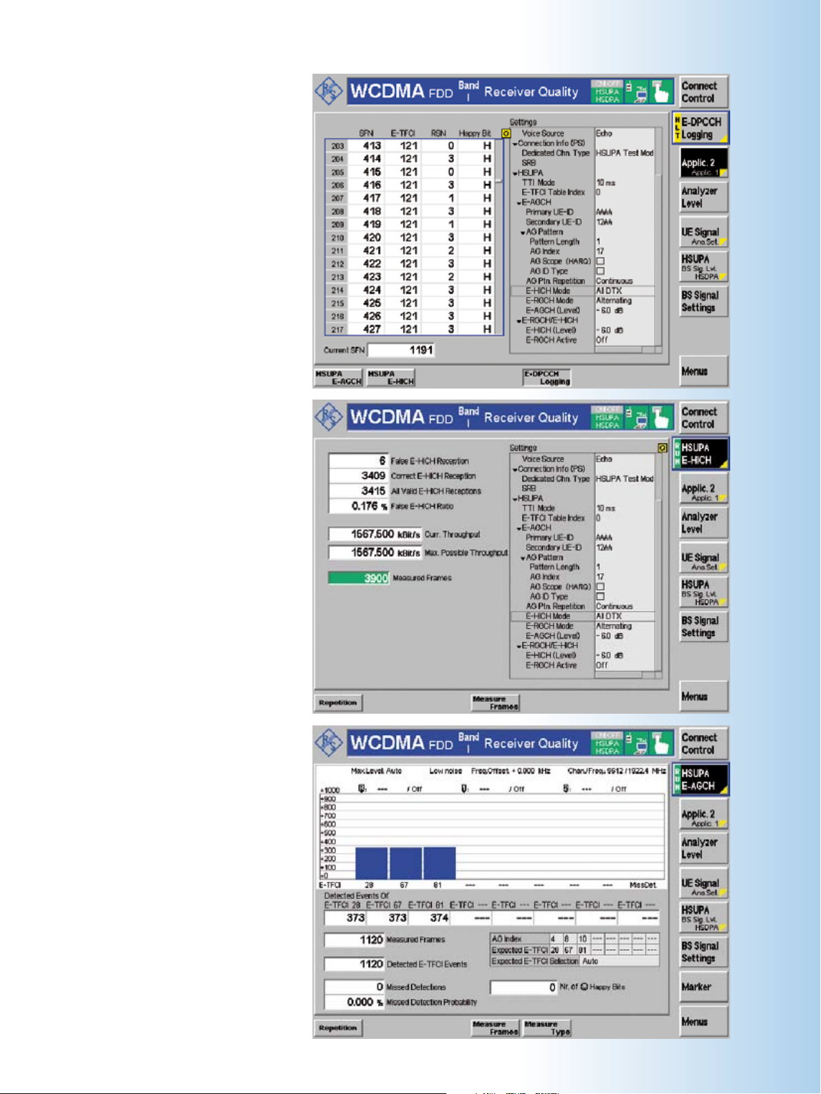
The E-DPCCH logging application
of the receiver quality measurement provides the E-TFCI (transport
format combination identifier), RSN
(radio sequence number indicating
retransmission or new transmission),
and the happy bit (reveals whether
the UE is happy with the granted
recourse) that the UE returns in a
sequence of 1000 consecutive TTIs.
By evaluating the UE-reported radio
sequence number (RSN) on the UL
E-DPCCH, the E-HICH detection per-
formance is measured. The UE has
to react as specified in cases where
the DL E-HICH contains all ACKs or
all DTXs. In the ¸CMU200, a
layer 1 throughput measurement
based on the analysis of the uplink
E-TFCIs that are used is also includ-
ed in this measurement screen.
For the A-GCH detection perfor-
mance measurement, the tester
continuously transmits a defined
sequence of absolute grant values
(AG) in the DL E-AGCH, where the
DUT has to follow the AG settings
with the correct UL E-TFCIs on the
UL E-DPCCH. Since the UL E-TFCI
to be used depends on various ad-
ditional parameters besides the AG
value, the ¸CMU200 calculates
the expected E-TFCIs automatically
based on all relevant settings, which
makes this measurement very easy
to use.
¸CMU200 Universal Radio Communication Tester 25
26 ¸CMU200 Universal Radio Communication Tester
WCDMA evolution – high-speed uplink packet access
presence of HSUPA channels. In signaling, more variety is possible and full flexibility of the ¸CMU200 can be used
to configure the downlink channels and
analyze the uplink signal coming from
the DUT. This goes beyond the standard
RF measurements and also includes
HSUPA performance tests as specified in
3GPP TS 34.121 chapter 10.
New required measurements
Rel. 6 of the 3GPP TS34.121 describes
different measurements for HSUPA in
chapter 5 (transmitter characteristics)
and chapter 10 (performance requirements for HSUPA). All these tests are to
be carried out in HSPA test mode connection that includes both the HSDPA
test mode and the HSUPA test mode. In
the ¸CMU200, various test mode
RABs are supported.
On the transmitter side, the tests are
standard RF tests such as power and
spectrum measurements in the presence of the HSUPA channels. For the
performance tests, the decoding performance of the UE for the different DL
channels under conditions of fading is
tested. These tests and the required test
mode RAB setups are supported by the
¸CMU200 and will be expanded over
time. At present, no dedicated receiver
measurements are specified for HSUPA.
Furthermore, the test of the physical layer throughput is certainly of interest and
of importance. Also, when real user data
is used for traffic in an end-to-end connection between a client and a server
(e.g. IP-based applications such as FTP
or video streaming), the throughput evaluation in the uplink and downlink over
time is of great interest. All of this is also
easily possible on the ¸CMU200.
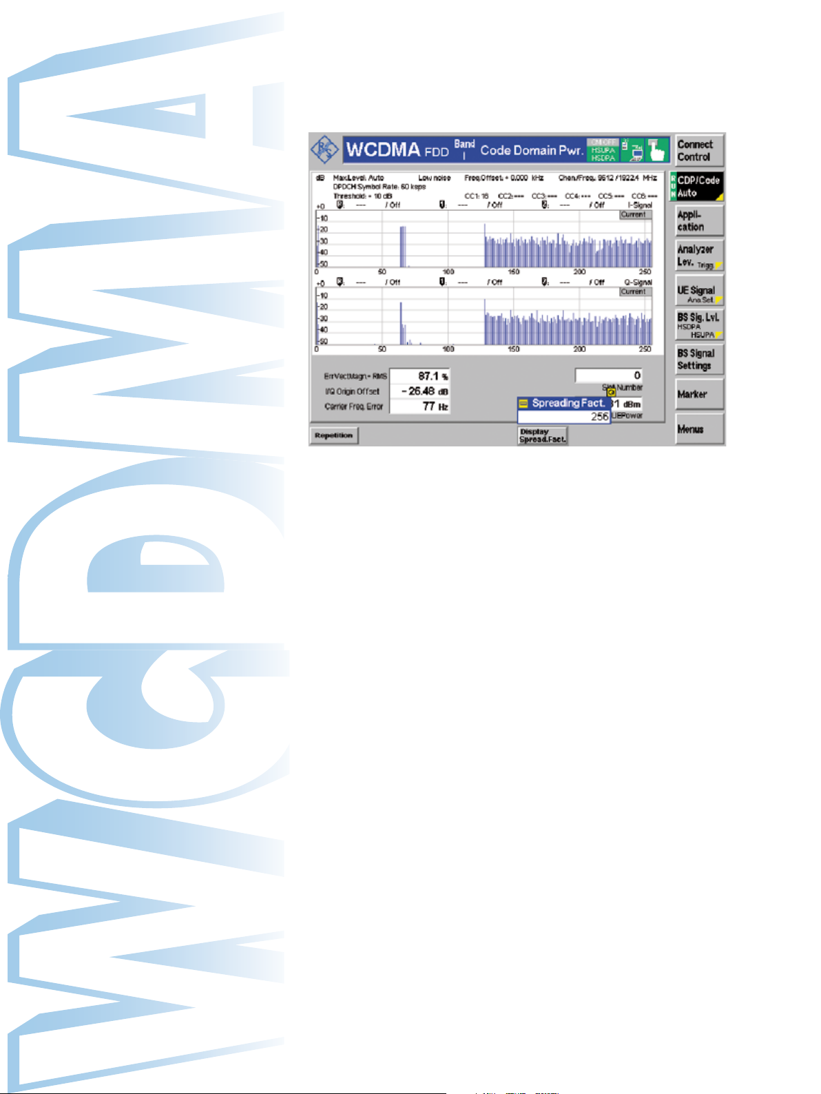
In the code domain power measurement on the ¸CMU200, the user can easily verify which code
channels are present in the uplink signal coming from the DUT. This is a valuable tool especially in
R&D on early UE designs. Shown above is a signal that contains WCDMA channels (DPDCH and
DPCCH) as well as HSDPA (HS-DPCCH) and HSUPA channels (E-DPCCH and E-DPDCHs).
Transmitter measurements
In HSUPA operation, up to five additional
uplink channels are in place; and in test
mode connections, the HSDPA uplink
channel HS-DPCCH with its special characteristics is also present. This fact calls
for additional measurements on the transmitter of the mobile phone. Specifically,
measurements that check the spectral
behavior of the UE are of interest. Furthermore, the maximum output power of
the UE once again needs to be checked
against the defined nominal behavior.
The ¸CMU200 can perform the measurements for the transmitter characteristics as defined in the 3GPP TS34.121
RF test specification.
All other standard transmitter measurements on the ¸CMU200, e.g.
modulation or code domain power measurements, take the additional uplink
channels into account as well. The code
domain power measurements in particular yield valuable additional information
about the new channels such as the ap-
plied uplink power influenced by the
gain factors for each code channel.
Performance measurements
In addition to the transmitter characteristics, items defined in chapter 10 of
3GPP TS 34.121 related to HSUPA performance tests are also covered in the
¸CMU200.
In the E-HICH detection performance
measurement, the receive characteristics
of the E-DCH HARQ ACK indicator channel (E-HICH) based on the determination
of the missed ACK and false ACK probability are evaluated as defined in
TS34.121/10.2.1. By evaluating the UEreported radio sequence number (RSN)
on the UL E-DPCCH, the E-HICH detection performance is measured correctly
regardless of the DL E-HICH pattern.
According to the 3GPP specification, the
DL E-HICH has to transmit all ACKs or all
DTXs, but the ¸CMU200 can also be
set to transmit all NACKs or an alternating pattern as well as a real-world scenario “react on UL CRC”.
HSUPA highlights of the
¸CMU200
Generation of E-AGCH, E-RGCH, and
◆
E-HCH channel with full flexibility with
regard to grant patterns and feedback
pattern
E-HICH interaction, where the
◆
¸CMU200 sends the answer in accordance with the received uplink signal
(react on UL CRC mode)
Transmitter measurements maximum out-
◆
put power, spectrum emission mask, and
ACLR in accordance with chapter 5 of
3GPP TS 34.121
Receiver measurements by evaluating
◆
the data throughput based on uplink
E-TFCIs used and CRC check on the UL
data
E-DPCCH logging capability for in-depth
◆
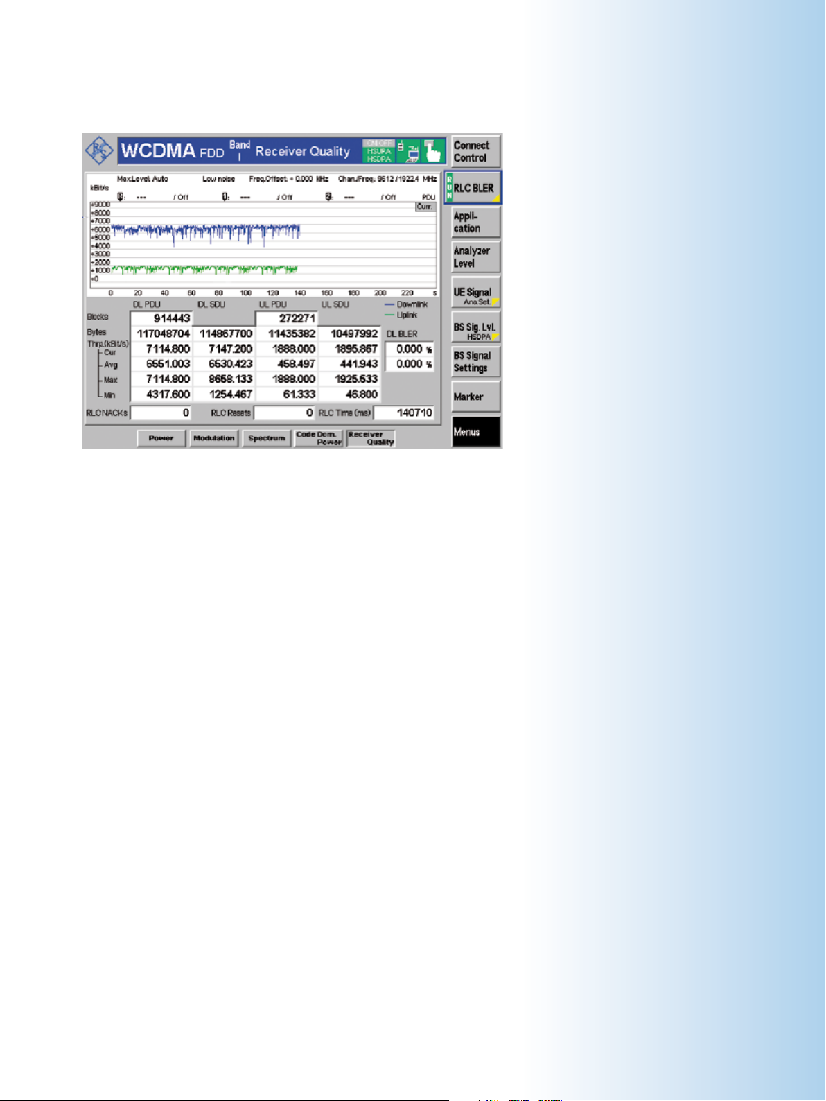
Full data rate HSPA throughput evaluation on the RLC layer in the uplink and downlink over time
is easily possible on the ¸CMU200 application testing solution for 3G when real user data is
used for traffic in an end-to-end connection between a client and a server (e.g. IP-based applications such as FTP or video streaming).
In the E-HICH performance measurement, a layer 1 throughput measurement based on the analysis of the uplink
E-TFCIs that are used is also included in
the ¸CMU200. This measurement also performs a CRC check of the received
transport blocks to make sure that only
correct UL data is taken into account for
the throughput.
granted E-TFCIs. Since the UL E-TFCI to
be used depends on various additional
parameters besides the AG value, the
¸CMU200 calculates the expected ETFCIs automatically based on all relevant
settings, which makes this measurement
very convenient to use. Moreover, the
measurement can be used as a general
UL E-TFCI histogram and any E-AGCH val-
ues can be used. This also makes it possiIn the A-GCH detection performance
measurement, the receive characteristics of the E-DCH absolute grant channel
(E-AGCH) based on the determination of
ble to perform measurements such as the
TS34.121/5.2B maximum output power
with HS-DPCCH and E-DCH, where the UL
E-TFCI that is used is of interest.
missed detection probability is evaluated
as defined in TS34.121/10.4.1. To do this,
the tester has to continuously transmit a
defined sequence of absolute grant values
(AG) in the DL E-AGCH, where the DUT
has to follow the AG settings with the correct UL E-TFCIs on the UL E-DPCCH. The
missed detection probability is evaluated
based on the received E-TFCIs.
As an additional measurement applica-
tion, the ¸CMU200 makes it possible
to log and decode the content of the UL
E-DPCCH in detail over 1000 TTIs. All
transmitted information such as the UL
E-TFCI (transport format combination
identifier) that is used, indicated RSN
(radio sequence number indicating re-
transmission or new transmission), and
In the ¸CMU200, a happy counter
makes sure that only TTIs where the UE
is unhappy are taken into account in or-
the happy bit (reveals whether the UE
is happy with the granted recourse) are
displayed.
der to guarantee that the UE is using the
¸CMU200 Universal Radio Communication Tester 27
analysis
Performance measurements on E-HICH
◆
and E-AGCH channels to verify UE detection performance
Configuration capabilities for the power
◆
offset parameters ∆E-DPCCH and reference E-TFCIs to control the power of the
uplink channels
Multiple test mode RAB types:
◆
12.2 kbit/s RMC + HSPA (with closed
–
loop mode 1 RLC TM and loop mode 2)
3.4 kbit/s SRB RAB + HSPA
–
12.2 kbit/s RMC + HSPA according to
–
3GPP TS34.108
12.2 kbit/s (+HSPA), where the HSPA
–
part is paged independently as a PS
RAB on top of RMC

28 ¸CMU200 Universal Radio Communication Tester
TDMA in the ¸CMU200
TDMA overview
The broad acceptance of TDMA (IS-136)
is based on its very flexible and powerful technology as well as on its compatibility with AMPS, which is widespread.
Derived from analog AMPS, the TDMA
standard is ready for step-by-step evolution to the third generation of mobile
radio technology. This fact shows the
need for a test instrument that is flexible
enough to cover all future needs as well
as the current standards.
For TDMA (IS-136) signaling functionality,
the ¸CMU200 requires the universal
signaling unit (¸CMU-B21) as well as
the software option ¸CMU-K27 for
the cellular band or ¸CMU-K28 for
the PCS band.
Due to the highly user-friendly menu
concept, the ¸CMU200 provides
quick access to all required measurements, optimizing handling and thus efficiency.
Signaling mode
The ¸CMU200 simulates a TDMA
base-station RF interface including
the signaling protocol so that a mobile
phone can be tested with regard to different signaling parameters. All necessary network and base-station parameters can be set, such as control and traffic channel configuration, neighboring
channels setup, etc. A MAHO report can
also be generated.
Non-signaling mode
The non-signaling mode is for generat-
ing and analyzing TDMA (IS-136) signals
in the frequency range from 10 MHz to
2.7 GHz. The ¸CMU200 provides
TDMA-specific measurements such as:
Power
◆
Modulation
◆
Spectrum
◆
Power versus time
◆
BER
◆
TDMA (IS-136) development
With its superb versatility, the
¸CMU200 is the most suitable tool
for the development of mobile phones.
Four configurable RF connectors are pro-
vided to enable flexible signal generation
and analysis. The power meter can eval-
uate signals in a range from –80 dBm to
+47 dBm, whereas the generator out-
puts signals from –130 dBm to +13 dBm.
The clearly structured and user-friendly
menu together with the clear-cut screen
layout provide quick access to all fea-
tures and ensure trouble-free monitoring
of the device under test.
Quality assurance
Due to its high measurement repeatability and accuracy, the ¸CMU200
is the right choice to ensure a consistently high level of quality in production.
TDMA-specific measurements such as
BER, error vector magnitude (EVM) and
EVM10, where only the first 10 symbols
are taken into account, provide an excellent test platform to ensure the production of high-quality devices.
Production of mobile phones
The production of mobile phones requires time-efficient and cost-effective
means that ensure both high throughput
and state-of-the-art accuracy. Owing to
the unique IEC/IEEE bus concept of the
¸CMU200, these two goals can be
easily achieved in production lines. The
intelligent handling of the received GPIB
commands optimizes the measurement
speed for all TDMA-specific measurements. In practice, this will mean significantly shorter test time and enhanced
test yield.
Acoustic measurements
The implemented ACELP speech coder
is able to encode and decode real audio
signals and allows the ¸CMU200 to
be used also in real acoustic measurement applications. This is equivalent to
the CDMA2000® and GSM implementation of the ¸CMU200. The TDMA
speech coder provides analog inputs and
outputs and a connector for an external
handset. It requires the hardware option
¸CMU-B52 and can also be combined with the internal Audio Analyzer/
Generator ¸CMU-B41.
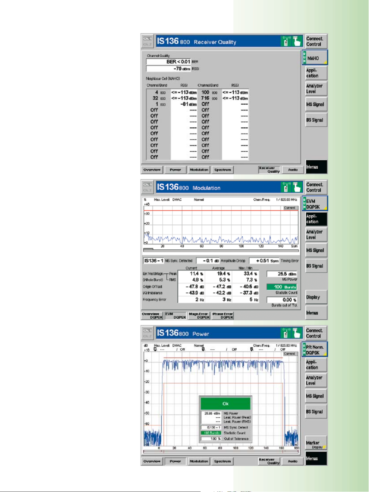
The mobile phone reports the re-
ceived signal strength (RSSI) of
the observed channels back to the
¸CMU200 where the RSSI is
displayed in the MAHO report list.
It is possible to configure the neigh-
boring channels in the network
setup. The reported BER can also be
monitored.
The modulation menu allows the
phase error, frequency error and the
error vector magnitude to be mea-
sured. The measurement results are
displayed graphically. Additional
measurements such as amplitude
droop and timing error are taken as
well and displayed numerically in
the same screen.
In the power menu, the mobile
phone output power of the short
burst or the normal burst is dis-
played. The ¸CMU200 also en-
ables leakage power measurements
which indicate the mobile phone
power output in timeslots not used.
¸CMU200 Universal Radio Communication Tester 29
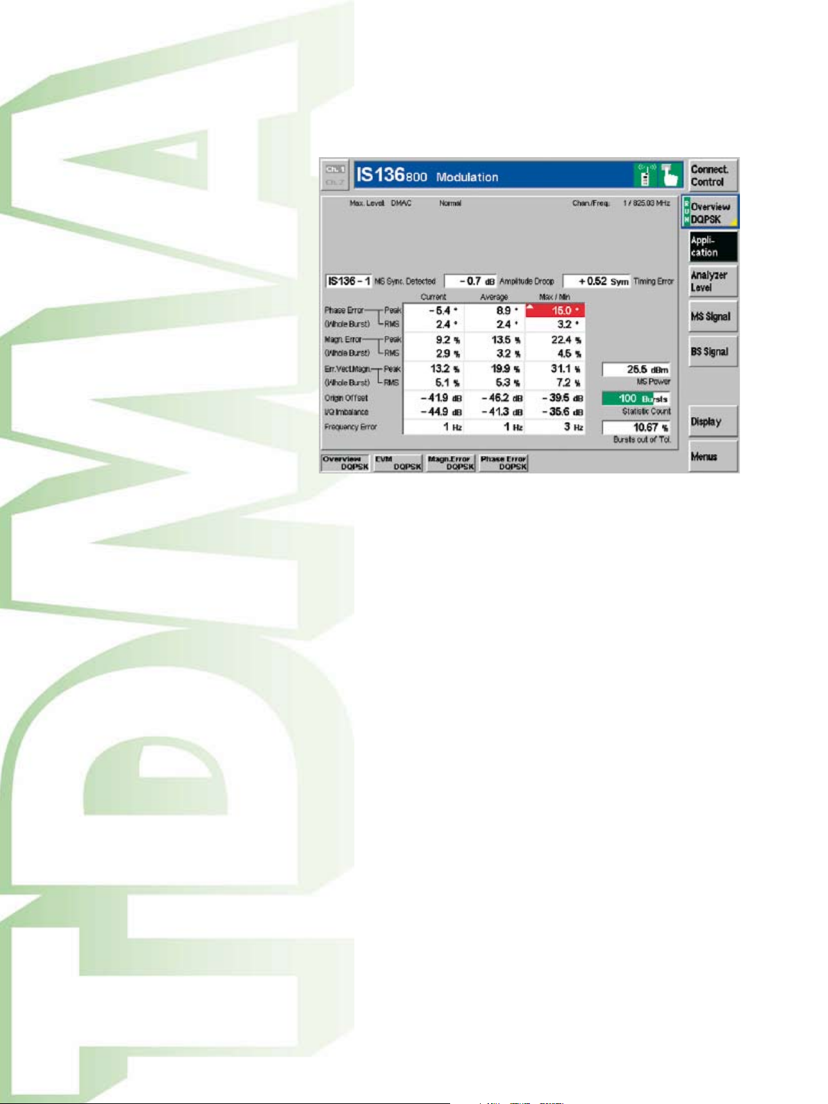
30 ¸CMU200 Universal Radio Communication Tester
Handoffs
Handoffs are part of the IS-136 specification. Handoffs between PCS and cellular bands as well as from and to AMPS
are defined and have to be tested. The
¸CMU200 supports IS-136 handoffs
from 800 MHz to 1900 MHz (interband
handoff) and vice versa. Handoffs from
1900 MHz or 800 MHz to AMPS and vice
versa are also possible (intermode handoff) with the ¸CMU200.
Switching standards
The flexibility of the ¸CMU200
makes for quick and simple switching
between two different standards. This
is very important for IS-136, which is a
dual-mode standard containing a digital
(TDMA) and an analog mode (AMPS).
The handoff between TDMA and AMPS
can be achieved by simply pressing a
button. This results in a very versatile
test concept to improve the flexibility
and throughput of production lines.
In the modulation overview menu, error vector magnitude (EVM), phase error and magnitude
error are measured simultaneously and displayed in a numeric table. The user can choose either
EVM, where the entire burst is considered, or EVM10, where only the first ten symbols are taken
into account.
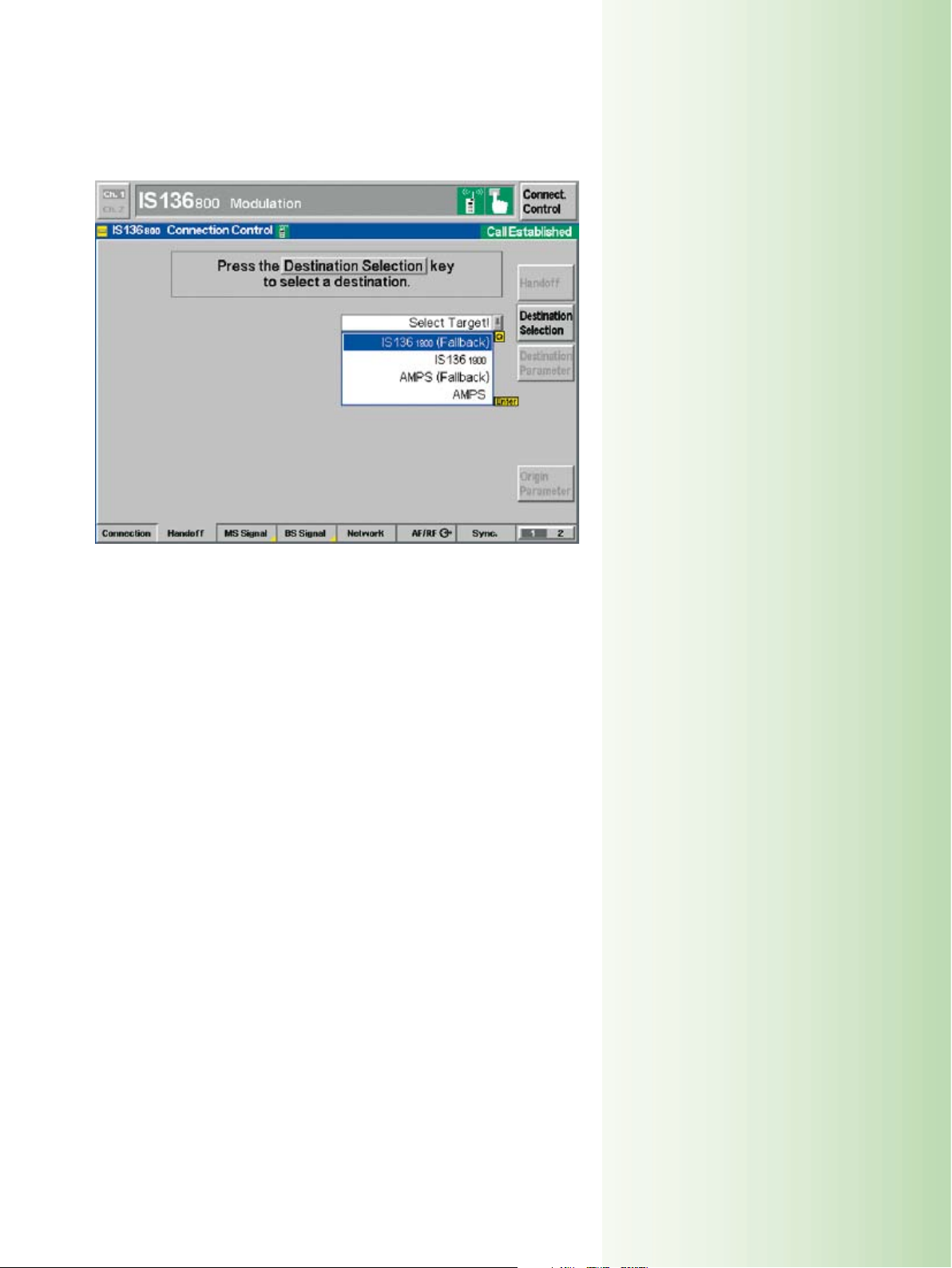
Handoffs from cellular band (800 MHz) to PCS band (1900 MHz) can be tested as well as to and
from AMPS. Before handoff to a new network, the parameters for the target network can be set.
This results in a large variety of different test scenarios.
TDMA highlights of the
¸CMU200
Basic features
Call to or from mobile phone
◆
Handoff to AMPS
◆
Dual-band handoff
◆
Signaling measurements
MAHO report
◆
Power versus time
◆
Short burst
–
Normal burst
–
Modulation
◆
Phase error
–
Magnitude error
–
EVM/EVM10
–
Overview of phase/magnitude and
–
EVM simultaneously
Spectrum
◆
Adjacent channel power due to switch-
–
ing or modulation
Overview
◆
Signaling information
–
Non-signaling measurements
Modulation
◆
Spectrum
◆
Power versus time
◆
BER
◆
¸CMU200 Universal Radio Communication Tester 31

32 ¸CMU200 Universal Radio Communication Tester
AMPS in the ¸CMU200
AMPS overview
Analog AMPS (advanced mobile phone
system) is a standard system for analog mobile phone service in the United
States and is also used in other countries. It is based on the frequency spectrum allocation for cellular service established by the Federal Communications
Commission (FCC) in 1970. Introduced by
AT&T in 1983, AMPS became the most
widely deployed cellular system in the
United States.
AMPS options
Although AMPS is a first generation analog standard, a substantial demand for
mobile radio testers covering this standard will continue to exist in the future.
Especially in the United States, dualmode CDMA2000®/AMPS and TDMA/
AMPS phones are very common.
By combining the digital standards with
analog AMPS, the network operators
offer their customers the advantages of
the digital standards and ensure nearly
100 % coverage in North America. As a
consequence, Rohde & Schwarz is offering analog AMPS in addition to the digital standards TDMA and CDMA2000®.
These options add analog AMPS functionality to the ¸CMU200 base unit:
AMPS measurements and
features
As for other standards, there are two
categories of AMPS measurements:
Transmitter tests
◆
for verifying the transmit part of a
mobile phone
Receiver tests
◆
for verifying the receive part of a
mobile phone
AF level search routine
The AF level search routine in the TX test
menu allows the user to set the desired
frequency deviation of the mobile phone
transmitter at a keystroke, the level of
the ¸CMU200 modulation generator
being automatically corrected.
Sensitivity search routine
The sensitivity search routine in the RX
test menu automatically searches for the
receiver input level at which a selectable
SINAD of the demodulated signal can
still be attained.
The following lists provide an overview
of the most important tests implemented
in the ¸CMU-K29 option.
Transmitter measurements
Carrier power
◆
Carrier frequency error
◆
SAT frequency error/peak deviation
◆
ST frequency error/peak deviation
◆
Modulation noise and distortion
◆
Hum and noise
◆
Electrical AF response
◆
Modulation distortion
◆
Residual AM
◆
Receiver measurements
Sensitivity
◆
Hum and noise
◆
SINAD
◆
Distortion
◆
AF voltage
◆
Electrical AF response
◆
Residual AM
◆
Audio deviation
◆
¸CMU-B21 (universal signaling
◆
unit)
¸CMU-B41 (audio generator/
◆
analyzer)
¸CMU-K29 (AMPS test software)
◆
The hardware options ¸CMU-B21
and ¸CMU-B41 are suitable for
other standards as well.

TX AF response measurement: the pre-emphasis characteristic of the mobile phone transmitter is
verified by a single-shot measurement.
Using the TX and RX AF response menus
ments are of course preconfigured in line
with specifications, but their settings can
be modified for individual measurements.
The RX and TX electrical AF response
measurements in AMPS are usually defined as frequency sweep versus AF
of the ¸CMU200, the AF response
is measured simultaneously at 20 test
points with user-programmable level
and frequency and then checked against
specified tolerances (see screenshot
above).
range. The ¸CMU200 offers a much
faster and more modern alternative.
AMPS highlights of the
¸CMU200
Benefits of base unit
Platform supporting CDMA2000®, TDMA
◆
and AMPS in one box
Wide frequency range allowing dual-
◆
mode/dual-band testing required for
CDMA2000® and TDMA
See base unit section
◆
AMPS features
Powerful signaling capabilities
◆
Base station simulation
◆
Mobile or base station originated call
◆
connect/disconnect
Short measurement time ensuring high
◆
throughput
Combined measurements
◆
Benchmark-breaking IEC/IEEE bus speed
◆
Simple interactive operation, standard-
◆
ized MMI
No specialized network knowledge re-
◆
quired
Various handoffs from CDMA2000®/
◆All the filters required for the measure-
TDMA and to TDMA supported
¸CMU200 Universal Radio Communication Tester 33

MA2000 1x
34 ¸CMU200 Universal Radio Communication Tester
CDMA2000® 1xRTT in the ¸CMU200
CDMA2000 1xRTT overview
CDMA2000 1xRTT is member of the
CDMA2000 family of standards.
CDMA2000 1xRTT (CDMA2000 1x) was
recognized by the International Telecommunications Union (ITU) as an IMT2000 standard in November 1999, and
with the start of commercialization in
October 2000 it was the first IMT-2000
technology deployed worldwide.
CDMA2000 1x benefited from the extensive experience acquired through several
years of operation of cdmaOne systems.
CDMA2000 1x handsets are backwards
compatible with cdmaOne systems.
The designation “1xRTT” (1x Radio
Transmission Technology) is used to
identify the version of CDMA2000 radio
technology that operates in a single 1.25
MHz radio channel (compared to three
1.25 MHz channels in 3xRTT). 1xRTT almost doubles voice capacity over IS-95
networks. Although capable of higher
data rates, most deployments have limited the peak data rate to 153 kbit/s.
CDMA2000 1x networks are not only
widely used in North and South America
as well as in Asia, but CDMA2000 1x is
also becoming increasingly important
in Northern and Eastern Europe in the
450 MHz band. More than 250 operators
worldwide have selected CDMA2000,
and there are over 380 million subscribers using CDMA2000 (1xRTT and 1xEVDO).
CDMA2000 1x operates worldwide in
different frequency bands. Presently,
the standard defines 17 different band
classes, all of which are covered by the
¸CMU200. Additional band classes
can be integrated easily as the market
evolves.
CDMA2000 1x functionality
Implementation of the CDMA2000 1x
standard in the ¸CMU200 is currently
based on TIA/EIA-2000 Rev. 0; the tests
provided by the ¸CMU200 are currently based on TIA/EIA-IS-98-F. Regular
adaptations to new releases will be made
available as the market requires. The measurement concept in the ¸CMU200 is
based on ProbeDSP™ technology, which
permits high-speed measurements. The
emphasis is on fast measurements and
clear and concise representation.
Like all mobile radio networks supported
by the ¸CMU200, there is a distinction between signaling and non-signaling
mode. All major network, base station,
and link parameters are clearly organized
and configurable. The implementation of
CDMA2000 1x in the ¸CMU200 takes
into account all important features of the
standard.
For instance, the ¸CMU200 supports
the quick paging channel (QPCH) which is
used to extend battery lifetime. In addition
to the normal configuration, it is possible
to define in the test setup whether or not
the QPCH addresses the DUT. This ensures
that the mobile phone observes the QPCH
instead of the normal pilot channel. Above
all the configuration change indicator (CCI)
bits can be set to enable or disable.
CDMA2000 1x forward power control enables the mobile station to control the
output power of the base station in the
dedicated channels. Measurements in the
¸CMU200 allow a comprehensive
function check of this CDMA2000 1x feature. The ¸CMU200 supports also new
features of the standard such as MEID emulation or the call configuration and setup
in service option 68, i.e. a voice call based
on the EVRC-B speech codec.
Signaling mode
In signaling mode, all major parameters of a mobile phone can be checked
with a connection established. The
¸CMU200 simulates a CDMA base
station, allowing the mobile phone to be
tested as in a real network. The signaling mode is not only needed in production (e.g. final test) but also in service
and development.
The ¸CMU200 provides a large set
of different connection types (service
options), making the tester ideal for both
R&D and production purposes.
The following service options are currently
supported:
Test loop service options: SO 2, SO 9,
◆
SO 55
Speech service options: SO 1, SO 3,
◆
SO 17, SO 68, SO 0x8000
Test data service option: SO 32
◆
IP end-to-end data connection: SO 33
◆
Short message service (SMS): SO 6,
◆
SO 14
The range of functions is as follows:
Power measurements
◆
Minimum/maximum output power
–
High-speed narrowband power
–
Gated output power
–
Open-loop time response
–
Access probe power
–
Standby power
–
Range tests by using user-
–
configurable power control bit
patterns
Modulation (both RC1/2 and RC3/4)
◆
Error vector magnitude (EVM),
–
magnitude error, phase error,
waveform quality, carrier feedthrough, frequency error
I/Q analyzer
◆
Eye diagram, constellation/vector
–
diagram

Cable
connections
Home
network
Web server,
mail server, etc
R&S®CMU200
(base station)
Mobile node
(mobile station)
Foreign
network
Foreign agent
Home agent
Virtual
access point
of mobile node
Data from/to
mobile station
Internet
IP tunnel
(¸CMU-B87 option) captures, interprets, and
displays the CDMA2000 1x forward and reverse
link messages between an ¸CMU200 and a
mobile station. For SO 33 calls, it also displays
the PPP forward and reverse link messages
(LCP, IPCP, PAP, CHAP protocols) differentiated
The Message Monitor
in terms of colors.
Typical test setup for mobile IP link with mobile
station and reference to home agent and foreign
agent.
¸CMU200 Universal Radio Communication Tester 35

CD
MA2000 1x
36 ¸CMU200 Universal Radio Communication Tester
CDMA2000® 1xRTT in the ¸CMU200
Code domain power
◆
Code domain power
–
Code domain error power
–
Channel power
–
Reverse pilot channel to code
–
channel time/phase tolerance
Spectrum
◆
Adjacent channel power (ACP)
–
measurements at four different
user-definable frequencies in a
±2 MHz range
Receiver quality measurements
◆
Frame error ratio (FER) on FCH,
–
SCH0
Dynamic range, sensitivity, and
–
other user-selectable test environments
Forward power control measure-
–
ment
Handoffs
◆
Implicit handoffs (RF channel,
–
Walsh code, PN offset, frame
offset)
Inter-band handoff
–
Handoff to AMPS
–
Non-signaling mode
The module test – without complete call
setup – allows process verification and
calibration of the DUT’s receiver and transmitter. For this purpose, measurements in
non-signaling mode are performed.
In the non-signaling mode the
¸CMU200 provides CDMA-specific
measurements and incorporates a signal
generator that delivers CDMA-specific
signals with pilot, sync, paging, and traffic channels. All major parameters can
be configured, e.g. the relative levels of
the individual code channels or the power control bits. In addition, the long code
mask can be controlled and the sync
channel content adjusted. The transmitter and receiver of the ¸CMU200
can be set independently of each other
and of the frequency bands, which al-
lows analysis of intermediate frequen-
cies, for example.
The range of functions is as follows:
Power measurements
◆
High-speed narrowband power
–
Modulation (both RC1/2 and RC3/4)
◆
Error vector magnitude (EVM),
–
magnitude error, phase error,
waveform quality, carrier feedthrough, frequency error
I/Q analyzer
◆
Eye diagram, constellation/vector
–
diagram
Code domain power
◆
Code domain power
–
Code domain error power
–
Channel power
–
Reverse pilot channel to code
–
channel time/phase tolerance
Spectrum
◆
Adjacent channel power (ACP)
–
measurements at four different
user-definable frequencies in a
±2 MHz range
Power versus frame
◆
¸Smart Alignment
◆
CDMA2000 1x development
The well-structured, user-friendly menu
design and the clear-cut screen layout
provide quick access to all features and
ensure trouble-free monitoring of the
device under test (DUT).
Using the ¸AMU200A baseband
fading simulator and the ¸CMU200
with optional I/Q IF interface, fading
conditions may be simulated and the re-
sults evaluated with the ¸CMU200.
In contrast to RF fading, a baseband fad-
ing system makes it possible to maintain
the high accuracy of the CDMA2000 1x
signal in the forward link provided by the
¸CMU200. Furthermore, baseband-
faded testing usually comes at a much
lower cost than an RF fading solution.
In addition to testing various RF parameters, the ¸CMU200 allows the
verification of the acoustic quality of a
CDMA2000 1x phone. The decisive factor
for the acoustic quality of a mobile phone
is the audio signal. For quality verification purposes, a speech coder is required
in the radiocommunication tester. The
analog signals from the mobile phone’s
microphone are converted into digital signals, which are transmitted after channel
coding. A speech decoder is then needed
to convert this digital data received by
the radiocommunication tester into audio
signals. The ¸CMU200 also supports,
simultaneously, the conversion of audio
signals input via the front panel (or internal audio generators) into the compressed
digital data that are required to test the
speaker in the mobile station.
The ¸CMU200 currently supports
the 8k speech coder (TIA/EIA-96-B), the
8k enhanced speech coder (TIA/EIA-127,
enhanced variable rate codec EVRC), i.e.
service options 1 and 3, as well as the
13k speech coder (TIA/EIA-733), i.e. service option 17, and the EVRC-B speech
coder service option 68. In combination
with an external audio analyzer such as
the ¸UPV, high-precision acoustic
measurements on CDMA2000 1x mobile
phones can be performed, e.g. in line
with the TIA/EIA-1042 standard.
For analysis of the signaling messages between the mobile and the ¸CMU200,
an optional message monitor is available. This is an extremely helpful tool for
analyzing and verifying the correct implementation of the protocol stack. For SO
33 connections, it also displays the PPP
forward and reverse link messages (LCP,
IPCP, PAP, CHAP protocols).

Code domain power is a highly important mea-
surement for mobile phones in CDMA2000 1x.
Since several code channels are transmitted
simultaneously in the reverse link, it must be
checked whether the power distribution of the
different channels complies with the test speci-
fication (TIA/EIA-IS-98-F).
The channel power measurement displays the
energy transmitted by the physical channels in
the reverse link, separated into I and Q signals.
Within a TDSO (SO 32) connection, the frame
error ratio (FER) on the fundamental channel
(FCH) as well as on the supplemental channel
SCH0 can be evaluated.
¸CMU200 Universal Radio Communication Tester 37

CD
MA2000 1x
38 ¸CMU200 Universal Radio Communication Tester
CDMA2000® 1xRTT in the ¸CMU200
In 3G networks, data links based on the
Internet protocol (IP) play a more and
more significant role. This calls for new
test procedures designed to verify the
functionality of IP-based links.
Numerous test scenarios are conceivable,
including data rate measurements under
ideal RF conditions, as well as with fading
or during handoff, and various application tests (e.g. access to mail servers, web
meetings, etc). In the past, such tests
required access to a real network. Now,
these tests can be performed without
a network by using the ¸CMU200,
which offers a wide range of configuration options for data connections (based
on service option 33).
The ¸CMU200 allows different test
setups to be implemented for different
application scenarios. In the simplest
case, the ¸CMU200 can be operated
in standalone mode (including mobile
IP) to perform data rate measurements
on the mobile phone under test. For this
purpose, the tester incorporates an internal FTP server that allows test files to be
exchanged.
By using a more complex test setup including an external home agent and foreign agent, mobile IP links to points such
as a web server or a mail server can be
set up, enabling to test complex applications.
Using a setup of two ¸CMU200, it
is possible to verify hybrid mode scenarios of a mobile phone in a combined
CDMA2000 1x and 1xEV-DO environment.
Production of mobile phones
The production of mobile phones re-
quires time-efficient and cost-effective
measures that simultaneously ensure
both high throughput and high yield.
Owing to market-leading accuracy and
to the unique IEC/IEEE bus concept of
the ¸CMU200, these two goals can
be easily achieved in production envi-
ronments. The ¸CMU200 provides
optimized high-speed measurements for
the calibration of the transmitter and the
receiver of a mobile phone.
Power versus frame
◆
is a realtime measurement that was
primarily designed for fast and accurate evaluation of defined power
steps of a transmitter over a wide
dynamic range.
¸Smart Alignment
◆
(¸CMU-K47 option) has been
designed for fast mobile transmitter
and receiver adjustments (TX and RX
calibrations) over a wide range of RF
channels and power levels. To enable parallel mobile transmitter and
receiver tests, the ¸CMU200 can
simultaneously change its generator
and analyzer settings after equal time
periods.
Repair applications (manufac-
turing and service centers)
With its outstanding versatility, the
¸CMU200 is also a suitable tool
for mobile phone troubleshooting. Four
configurable RF ports and a built-in RF
connector switch matrix (standard unit)
are provided to enable flexible signal lev-
el ranges and switching.
Switching standards
Fast switching between CDMA2000 1xRTT
and 1xEV-DO or any of the other numerous standards supported by the
¸CMU200 is a standard feature of the
instrument and can be achieved by simply
pressing a button.
Versatile production test layouts are possible, and true multimode test bays that
utilize the flexibility and throughput of
the ¸CMU200 are no longer a concept of the future.
¸CMU200 CDMA2000 1x
options
The following options are available for
CDMA2000 1x:
¸CMU-B83: CDMA2000 1x
◆
signaling unit
¸CMU-K83: CDMA2000 1x
◆
software for the 450 MHz bands
¸CMU-K84: CDMA2000 1x
◆
software for cellular bands
¸CMU-K85: CDMA2000 1x
◆
software for PCS bands
¸CMU-K86: CDMA2000 1x
◆
software for IMT-2000 bands
¸CMU-K87: CDMA2000 1x packet
◆
data application testing software
¸CMU-K47: ¸Smart Align-
◆
ment
¸CMU-B85: 8k QCELP, 8k EVRC,
◆
13k QCELP, EVRC-B speech coder
¸CMU-B87: interface for
◆
CDMA2000 1x data testing incl.
layer 3 message monitor software
¸CMU-U80: low jitter trig-
◆
ger output connector (for A-GPS
applications)

Modulation measurements allow users to check the MS transmitter. Parameters such as EVM,
phase error, and frequency error are displayed graphically.
The universal hardware and software
concept of the ¸CMU200 represents the optimum solution for the
development and challenges of the
CDMA2000 1x standard over the next
few years.
CDMA2000 1xRTT highlights of
the ¸CMU200
Support of currently 17 different band
◆
classes
CDMA2000 1x speech coder for
◆
high-precision acoustic measurements
Multiple connection types to cover most
◆
important test requirements in R & D, production, and high-level service labs
Extremely fast measurements
◆
Extensive non-signaling for high-speed
◆
innovative production test needs
Parallel RX/TX measurements ensuring
◆
high throughput in production environments
Comprehensive signaling mode
◆
functionalities
Graphical representation of measurement
◆
results best suited for R & D labs
Various handoffs supported, e.g. hand-
◆
off to AMPS, inter-band handoff, between service options and between
CDMA2000 1x and IS-95 connection
types during an established call
Readout and display of many mobile-
◆
phone-specific parameters (ESN, slotted
timer, station class mark, slot cycle index,
user zone identifier, etc)
MEID emulation support
◆
Quick paging channel and CCI bits can be
◆
individually set and enabled or disabled
Support of forward closed-loop power
◆
control tests as specified in IS-98-F sections 3.4.7, 3.4.8, 3.4.9
CDMA2000 1x/1xEV-DO hybrid mode
◆
scenarios with two ¸CMU200
Measurements under fading conditions
◆
supported (baseband fading; requires the
¸CMU-B17 option plus a fading generator such as the ¸AMU200A)
Single-box mobile IP emulation
◆
IP mobility support
◆
Fast switching between wireless appli-
◆
cations as a basic functionality without
shutdown and reboot
CDMA 2000 ® is a registered trademark of the Telecommuni cati ons Industry As sociatio n (TIA – USA).
¸CMU200 Universal Radio Communication Tester 39

40 ¸CMU200 Universal Radio Communication Tester
CDMA2000® 1xEV-DO in the ¸CMU200
CDMA2000 1xEV-DO (TIA/EIA-856-A), officially recognized by the ITU as an
IMT-2000 3G standard, is the latest step
in CDMA2000 evolution.
CDMA2000 1xEV-DO has been developed in order to make full use of the
advantages of an all-IP network; the air
interface has been optimized for data
transmission.
The 1xEV-DO access terminals being sold
are nearly all multimode devices, supporting both the existing CDMA2000
1xRTT standard and the new technology.
Unlike CDMA2000 1xRTT, 1xEV-DO uses
a time division multiple access method.
The spectral characteristics have not
changed with respect to CDMA2000
1xRTT, which enables in-band migration.
The protocol stack, however, is completely different from that of CDMA2000
1xRTT.
This makes the upgrade path very attractive for network operators, since
the measures necessary to modify the
radio access network (RAN) are more or
less reduced to exchanging a channel
card. Network operators, therefore, are
installing hybrid mobile radio networks
that support both CDMA2000 1xRTT and
CDMA2000 1xEV-DO, which allows them
to optimize the capacity for voice connections while at the same time offering
modern, profitable data services.
The structure of the 1xEV-DO protocol stack is mapped onto an advanced menu structure for use
by R&D and production engineers.
Improvements to reverse link (re-
CDMA2000 1xEV-DO Revision A (TIA-856-
A) is the first stage in a series of planned
upgrades of the 1xEV-DO standard.
1xEV-DO Rev. A introduces enhance-
ments to support quality of service
(QoS). These enhancements support la-
tency-sensitive and bandwidth-intensive
applications such as enhanced push-to-
talk, multiplayer gaming, laptop-based
video conferencing, voice over internet
protocol (VoIP) and instant multimedia
messaging (IMM). These enhancements
along with the increased data rates al-
low operators to provide integrated
voice, data and video services.
◆
garding peak data rate and sector
throughput)
Improved QoS mechanisms
◆
Expanded broadcast/multicast
◆
applications
CDMA2000 1xEV-DO functionality
The tests provided by the ¸CMU200
are based on the TIA-866-A minimum
performance requirements specification
for access terminals (AT).
The initial Release 0 standard provides
data rates up to 2.4 Mbit/s in the forward link and up to 153.7 kbit/s in the
reverse link. Revision A of the standard, now being deployed in numerous
networks around the world, provides a
maximum data rate of 3.1 Mbit/s in the
forward link and 1.8 Mbit/s in the reverse link.
The faster data rates, particularly on the
reverse link, will benefit users who need
to send large files such as photos or vid-
eo over their wireless connection.
The main differences between 1xEV-DO
Release 0 and Revision A are the fol-
lowing:
The ¸CMU200 simulates a
CDMA2000 1xEV-DO base station RF interface, providing the signaling flexibility
necessary to test the performance of a
mobile phone under the influence of different signaling parameters. These parameters are normally configured by the
network operator but can also be set by
the ¸CMU200 for test purposes.

The Statistic Overview display of the Receiver Quality application, showing the DUT’s received
packet errors during a RETAP connection. The achieved throughput (net rate) is calculated and
displayed as Forward Link Performance.
Due to its user-friendly menu concept,
the ¸CMU200 provides quick access
to all required measurements and optimizes the handling and thus the efficiency of complex measurement tests with
appropriate status messages and built-in
statistic functions.
The 1xEV-DO option provides extensive
testing capabilities both in test mode
and in a real-world emulation. Specifically, the ¸CMU200 supports FTAP/
FETAP as well as RTAP/RETAP and also
provides end-to-end data testing func-
The 1xEV-DO option supports the full
range of data rates and packet sizes avail-
able with CDMA2000 1xEV-DO Rev.A, i.e.
forward link rates up to 3.1 Mbit/s, re-
verse link rates up to 1.8 Mbit/s. FETAP/
RETAP testing as well as data testing is
supported at all rates.
In addition to FTAP/FETAP and RTAP/
RETAP, the ¸CMU200 provides true
dynamic network performance using de-
fault packet application support for real-
world throughput analysis and network
emulation.
tionality in a single-box solution. The
support of the default packet application
(DPA) allows the ¸CMU200 to be
operated as a host for an IP connection.
If the ¸CMU-B87 option is installed,
the end-to-end data capabilities are
In conjunction with a baseband fading
simulator from Rohde & Schwarz, more
accurate and cost-effective solutions
can be implemented than by using an
RF fader.
greatly enhanced by allowing a connection to an external network and its servers. Mobile IP support and IP throughput
statistics are provided by the ¸CMUK87 option.
CDMA2000 1xEV-DO signaling
measurements
Designed for use with the ¸CMU200
platform, it ensures accuracy, efficient test,
times and repeatability in 1xEV-DO test.
Using forward (enhanced) test application
protocol (FETAP/FTAP) and reverse (enhanced) test application protocol (RETAP/
RTAP) applications and the ¸CMU200,
the quality of the receiver and the transmitter of a DUT can be tested as defined by the
TIA-866-A minimum performance requirements standard.
With an FETAP connection, the quality of
a DUT receiver is determined up to a maximum data rate of 3.1 Mbit/s. In this measurement, the DUT returns, via the reverse
link, statistics and counts of received packets and erroneous packets that provide information about the connection quality. The
1xEV-DO option of the ¸CMU200 evalu-
ates the information received in various
ways, e.g. by carrying out packet error and
performance measurements to determine
the actual throughput as a function of the
packet size.
With an RETAP connection, the ¸CMU200
determines the quality of the DUT’s transmitter
and modulator. This can be done for data rates
ranging from 9.6 kbit/s up to max. 1.8 Mbit/s.
The DUT can thus be tested not only at a fixed
data rate but also over a range of data rates.
Switching standards
Off-the-shelf fast switching between
CDMA2000 1xEV-DO, CDMA2000 1xRTT,
HSPA, and any of the other standards supported by the ¸CMU200 – even firstgeneration cellular technology AMPS – is
part of the standard instrument capabilities
and may be achieved by simply pressing a
button.
¸CMU200 Universal Radio Communication Tester 41

42 ¸CMU200 Universal Radio Communication Tester
CDMA2000® 1xEV-DO in the ¸CMU200
Versatile production test layouts are possible, and true multimode test bays that
utilize the flexibility and throughput of
the ¸CMU200 are no longer a concept of the future.
The range of functions is as follows:
Transmitter measurements
Narrowband power
◆
Modulation
◆
Error vector magnitude (EVM),
–
magnitude error, phase error,
waveform quality, carrier feedthrough, frequency error
I/Q analyzer
◆
Eye diagram, constellation/vector
–
diagram
Code domain power
◆
Code domain power
–
Code domain error power
–
Channel power
–
Adjacent channel power (ACP) mea-
◆
surements at four different user-definable frequencies in a ±2 MHz
range
Receiver measurements based on test
connections (FTAP/FETAP, RTAP/
RETAP)
Receiver quality
◆
AT statistics
◆
Statistical overview at a glance
–
Control channel PER in connected
–
mode
Forward/reverse link quality
◆
Forward/reverse link performance
◆
The spectrum measurement provides comprehensive adjacent channel power (ACP) measure-
ments at four different user-definable frequencies in a ±2 MHz range.
CDMA2000 1xEV-DO non-sig-
naling test concept
Recent production measurement trends
have been moving away from “call es-
tablished“ based or “signaling“ based
testing toward a “module“ or “non-sig-
naling“ strategy. The main advantage
of this approach is reduced test time in
comparison to full signaling tests. It is
possible to implement vendor-specific
tests/procedures and easier to add new
test scenarios as the device under test
(DUT) matures. In addition, lack of sym-
metry between forward and reverse data
rates in CDMA2000 1xEV-DO makes tra-
ditional loopback testing less effective.
With its optional 1xEV-DO capability,
the ¸CMU200 offers a very flexible,
all-in-one solution including a 1xEV-DO
generator for receiver testing as well as
an extensive list of transmitter measure-
ments for testing CDMA2000 1xEV-DO
access terminals. The test concept is
based on direct control of the DUT with-
out complete signaling by the same computer that controls the ¸CMU200.
The DUT’s non-signaling mode is implemented via the serial diagnostic monitor interface which is already present
in most 1xEV-DO terminal designs. The
non-signaling mode minimizes test configuration and transition time between
tests. Enhanced measurement times and
optimized test sequences are a special
benefit especially in production environments, yielding higher throughput.
The option ¸CMU-K47 (¸Smart
Alignment) allows the DUT’s transmitter and receiver to be calibrated at once
over the entire frequency and level
range.
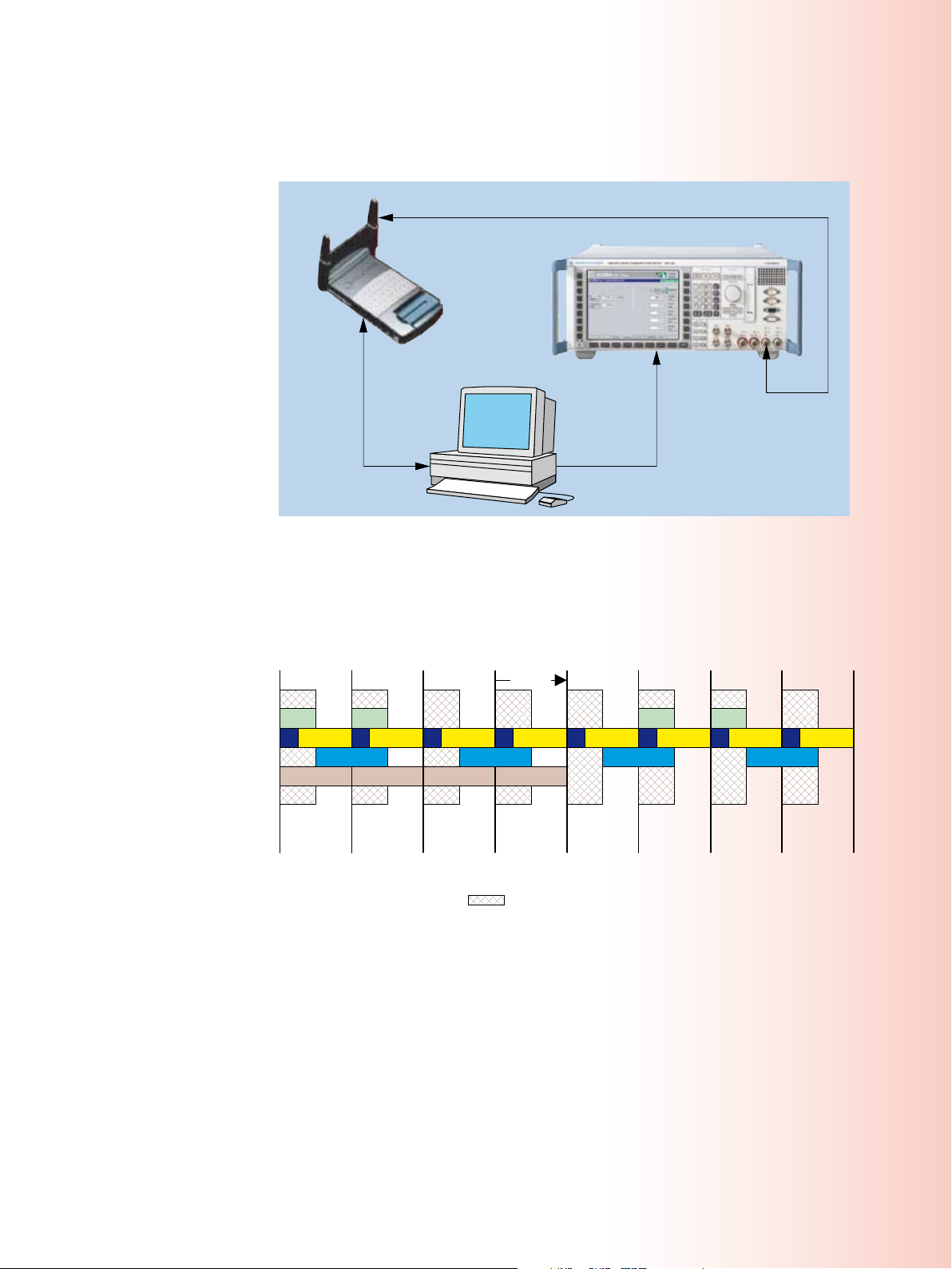
RRI
Pilot
Data
RRI
ACK
Pilot
Data
RRI
Pilot
RRI
ACK
Pilot
RRI
Pilot
Data
RRI
Pilot
Data
RRI
ACK
Pilot
RRI
Pilot
ACK = OFF
DRC = OFF
DATA = OFF
ACK = OFF
DRC = ON
DATA = ON
ACK = OFF
DRC = OFF
DATA = ON
ACK = ON
DRC = ON
DATA = ON
ACK = ON
DRC = ON
DATA = OFF
ACK
ACK = ON
DRC = OFF
DATA = ON
ACK = ON
DRC = OFF
DATA = OFF
ACK = OFF
DRC = ON
DATA = OFF
DRC DRCDRC DRC
One slot
Notes:
Measurement window
DRCLength = 2
DRCGating = ON
RF
Forward link and reverse link (for transmitter measurements)
R&S®CMU200 with 1xEV-DO generator
DUT
Reverse link
(PER statistics)
Interface for
DUT control
IEC/IEEE bus
Test setup: A test system using a non-signaling test mode is
virtually identical to most proto-
col-based production test setups.
It consists of a test controller, a
radiocommunications tester with
1xEV-DO option, and the actual de-
vice under test. The primary differ-
ence is that the device under test
operates in the non-signaling mode
while the test sequence is being
performed.
Channel filters: Three different
channel filters allow the reverse
link signal to be analyzed in eight
different signaling states. Users
may select whether or not to mea-
sure the signal at the time when
ACK, DATA, or DRC channel is
transmitted (ON or OFF). All modu-
lation measurements as well as the
code domain power measurement
support the channel filters.
¸CMU200 Universal Radio Communication Tester 43

44 ¸CMU200 Universal Radio Communication Tester
CDMA2000® 1xEV-DO in the ¸CMU200
The CDMA2000 1xEV-DO generator offers a high degree of flexibility. This
permits considerable flexibility in the
configuration of tests for the DUT. Both
1xEV-DO options for the ¸CMU200
support a wide variety of test configurations, and can configure the following
MACIndex
◆
Data rate
◆
Data pattern
◆
DRCLock mode
◆
Reverse power control mode
◆
Power level
◆
PN offset
◆
AWGN and frequency offsets
◆
The CDMA2000 1xEV-DO generator
(¸CMU-B88 option) affords an even
higher level of configurability. It is possible to generate traffic for up to 4 DUTs,
to change the scheduling system, and
control the number of other users in the
MAC burst. The ¸CMU-B88 option
of course supports 1xEV-DO Revision 0
and A signal generation. This option also
provides more extensive triggering capabilities.
CDMA2000 1xEV-DO non-signaling measurements
The ¸CMU200 provides a complete
set of extremely fast transmitter measurements. Most of the measurements
are presented in graphical form which
makes the test solution ideal for R&D.
A number of measurements can be configured to look at only certain combinations of reverse link code channels. This
allows in-depth analysis of transmitter
performance in various mobile operating modes.
Code domain power measurement (Rel. 0): The code domain power (CDP) includes the time-switching component between RRI and pilot channel. The ”blue” bar displays the CDP for the time the RRI
channel is up. The ”purple” bar shows the CDP value for the time the pilot channel is up.
The list below shows the
CDMA2000 1xEV-DO measurements:
Power measurements
General power measurement
◆
(e.g. for fast power phasing)
Code domain power
Code domain power
◆
Code domain error power
◆
Channel power
◆
Modulation measurements
Error vector magnitude (EVM)
◆
Magnitude error
◆
Phase error
◆
I/Q analyzer
Eye diagram, constellation/vector
◆
diagram
Spectrum measurements
Adjacent channel power (ACP) mea-
◆
surements at four different user definable frequencies in a ±2 MHz
range
Receiver measurements
Via DUT control interface in test
◆

Code domain power measurement (Rev. A):
The application shows the currently used
code space during an RETAP connection with
DRC index 10.
Code domain power measurement (Rev. A):
The channel power application displays the
code channels used with their relative energy,
and also shows the Walsh cover used for the
data channel, in this screenshot Q4Q2.
I/Q analyzer: The constellation diagram dis-
plays the I/Q position of the sample points in a
Y/X grid. This allows signal quality and modu-
lation complexity to be graphically observed
at a glance. This picture was taken during an
RETAP connection with DRC index 10.
¸CMU200 Universal Radio Communication Tester 45

46 ¸CMU200 Universal Radio Communication Tester
CDMA2000® 1xEV-DO in the ¸CMU200
CDMA2000 1xEV-DO options
The 1xEV-DO option of the ¸CMU200
is based on the ¸CMU-B83
CDMA2000 1x signaling unit. Due to the
flexible ¸CMU200 platform concept,
measurement capabilities for various applications can be configured for both signaling and non-signaling.
The ¸CMU-B89 1xEV-DO signaling
module provides the necessary hardware for CDMA2000 1xEV-DO Revision A,
CDMA2000 1xEV-DO Release 0, as well
as non-signaling-based testing.
To enhance the ¸CMU200 with
1xEV-DO signaling functionality, the
following options are available:
¸CMU-B83 model 22:
◆
CDMA2000 1x signaling unit
¸CMU-B89: CDMA2000 1xEV-DO
◆
signaling module
¸CMU-K839: CDMA2000 1xEV-
◆
DO software for the 450 MHz bands
¸CMU-K849: CDMA2000 1xEV-
◆
DO software for cellular bands
¸CMU-K859: CDMA2000 1xEV-
◆
DO software for PCS bands
¸CMU-K869: CDMA2000 1xEV-
◆
DO software for IMT-2000 bands
¸CMU-K47: ¸Smart Align-
◆
ment
¸CMU-B87: interface for
◆
CDMA2000 1xEV-DO data application
testing
¸CMU-K87: CDMA2000 1xEV-DO
◆
data application testing software
¸CMU-U80: low jitter trigger
◆
output connector (for A-GPS applications)
¸CMU-Z89: hybrid mode test kit
◆
I/Q analyzer: The eye diagram shows the decision path for the demodulation of the signal. This
application makes it possible to view the I or Q parts alone, or both at once.
The 1xEV-DO signaling functionality is al-
so available with the ¸CMU200V10,
the signaling tester for the service market.
To enhance the ¸CMU200 with
1xEV-DO non-signaling functionality
without signaling capability, the following options are available:
R&S CMU-B83 model 12:
◆
CDMA2000 1x signaling unit
R&S CMU-B88:
◆
CDMA2000 1xEV-DO generator
¸CMU-K47:
◆
¸Smart Alignment
R&S CMU-K88:
◆
CDMA2000 1xEV-DO test software
¸CMU-U80: low jitter trigger out-
◆
put connector (for A-GPS applications)
The 1xEV-DO non signaling functionality is also available with the
¸CMU200V30, the non-signaling
tester for board alignment and high volume manufacturing.
CDMA 2000® is a regi stered tr ademark of th e Telecommunicati ons Industry As sociatio n (TIA – USA).

The receiver quality measurement display shows the key results regarding the mobile´s receiver
performance.
This 1xEV-DO test solution is based on the ¸CMU200 high-performance radio
communication tester; it provides the additional benefits of extremely fast measurement speed, ease of programming, accuracy, reliability, and worldwide service and
support. These features help shorten the test development time, increase throughput, and minimize support costs. The first class support is not limited to production
demands, but makes the ¸CMU200 also ideal for use in R&D environments.
CDMA2000 1xEV-DO highlights of the
¸CMU200
Signaling and non-signaling
Support of currently 17 different band classes
◆
Graphical representation of measurement results
◆
best suited for R & D labs
Innovative measurements of code domain power,
◆
code domain peak error power, channel power
Channel filters allow the reverse link signal to be
◆
evaluated in eight different states
Spectrum measurements at four discrete fre-
◆
quency offsets (user-configurable)
Measurements under fading conditions
◆
(baseband fading)
Signaling
Comprehensive signaling mode functionalities
◆
Support of FTAP/FETAP and RTAP/RETAP test
◆
application protocol call processing
Control channel PER
–
Forward/reverse link PER
–
Reverse link quality
–
Forward/reverse link performance
–
Readout and display of many mobile-phone-spe-
◆
cific parameters (ESN, MEID, slot cycle index, etc)
Single-box mobile IP emulation
◆
IP mobility support
◆
Provides enhanced data throughput analysis
◆
with peak data rates up to 3.1 Mbit/s
Data channel connectivity tests high-speed
–
packet data connection to a real IP network
IP throughput monitor allows analysis of data
–
throughput using controlled data impairments
Combines CDMA2000 1xRTT with CDMA2000
◆
1xEV-DO test applications in one box for dual-mode
CDMA2000 1xRTT/1xEV-DO testing
Hybrid mode testing possible using multiple
◆
¸CMU200 instruments
RF channel and band class handoffs
◆
Non-signaling
Simultaneous testing of up to four access termi-
◆
nals in non-signaling mode
Reduced test times in comparison to full signal-
◆
ing tests
Extensive non-signaling for high-speed innova-
◆
tive production test needs
Power versus frame
–
¸Smart Alignment
–
Extremely flexible 1xEV-DO Revision 0 and A gen-
◆
erator allows vendor-specific tests and new test
scenarios, also for R&D
¸CMU200 Universal Radio Communication Tester 47

48 ¸CMU200 Universal Radio Communication Tester
Bluetooth® measurements in the ¸CMU200
General
The ¸CMU200 was the first
Bluetooth® test set on the market. It is
the only radiocommunications tester
worldwide to offer Bluetooth® as well as
all important mobile radio standards in a
single instrument.
Applications
The ¸CMU200 with the Bluetooth®
option is the ideal instrument for the production, development and maintenance
of any kind of device with an integrated
Bluetooth® interface.
Due to its modular platform concept, the
¸CMU200 is the ideal solution for all
cellular-standard mobile-phone production lines.
Parallel operation for high mea-
surement speed
Due to the high measurement speed
and large memory capacity of the
¸CMU200, transmitter and receiver
measurements can be carried out simultaneously. When measurements are performed in frequency hopping mode, a significant test depth is rapidly attained. Only
a few seconds are required between call
setup, transmitter and receiver measurements and call detach. Fast test cycles
ensure a fast return on investment.
Many convenient measurement
functions
The ¸CMU200 offers a large number of statistical monitoring and measurement functions. It is possible, for
instance, to define individual tolerances
for each measured value and to stop a
measurement sequence after a certain
number of measurements or when a tolerance has been exceeded. Besides the
common traces for power and modulation versus time, averaged minimum or
maximum traces can also be displayed
over a user-defined number of packets.
Signaling
Setting up a Bluetooth® connection
The ¸CMU200 acts as the master of
a Bluetooth® piconet, the DUT as a slave.
The ¸CMU200 is able to perform the
inquiry procedure for the identification
of all Bluetooth® devices within range
of the ¸CMU200. All devices found
are listed on the display and one of them
can be selected for the paging procedure.
The ¸CMU200 then establishes the
connection to the DUT and switches it to
test mode operation.
The inquiry procedure can be skipped if
the Bluetooth® device address of the DUT
is already known. In this case, a shorter
setup time for the connection can be
achieved. This is important for production
tests of Bluetooth® devices to increase
the maximum throughput of a production
line. In line with the Bluetooth® test mode
specification, the DUT has to be locally
enabled for test mode operation.
After a Bluetooth® link is established,
the ¸CMU200 sends test control
commands to the DUT to switch it to the
desired test mode. The ¸CMU200 is
then able to perform a number of transmitter and receiver measurements.
The ¸CMU200 is also capable of set-
ting up a normal Bluetooth® asynchronous connectionless (ACL) link without
activating the test mode. Via this normal
link, the power and frequency accuracy
of every DUT can be measured, regard-
less of whether the DUT has been locally
enabled for the test mode.
If a normal (ACL) link is used, the
¸CMU200 can switch the DUT to
the audio, hold, park and sniff modes.
Audio mode
In the audio mode, the ¸CMU200
establishes a synchronous connection-oriented (SCO) link to the DUT in addition to
the ACL link. The ¸CMU200‘s built-in
Bluetooth® audio codec supports CVSD as
well as A-law and µ-law coding. External
audio generators and analyzers can be
connected by means of one analog input
and output each on the ¸CMU200
front panel. A much more convenient alternative is the ¸CMU-B41 audio option. This option, in conjunction with the
Bluetooth® audio codec, makes it very
easy to carry out basic audio measurements on Bluetooth® DUTs.
Park, hold and sniff modes
The power consumption of a Bluetooth®
chipset is considerably reduced in these
three modes, making them particularly important in all battery-powered
Bluetooth® devices. The ¸CMU200
can switch the DUT to the park, hold or
sniff mode, making it possible to check
the reduced power consumption by
means of external test equipment.
Signaling information from the
DUT
The ¸CMU200 is able to display a
variety of information that is received
from the DUT (e.g. device name, version
numbers, service class, supported features).

Compliance with existing
Bluetooth® standards
The ¸CMU200 is compliant with
the Bluetooth® Core Specifications Version 1.1. The Bluetooth® test mode (Core
Spec. Part I:1) is implemented with
all commands needed to perform the
TX/RX measurements. In addition, the
¸CMU200 is capable of testing all
DUTs that support the new Bluetooth®
Core Specifications Version 1.2, since
the test mode specified in the new version does not include any changes relevant to the ¸CMU200.
The Bluetooth® RF Test Specification describes RF test cases for the Bluetooth®
qualification process. Although the
¸CMU200 was not designed for
qualification tests, the RF test specification was taken as a guideline for the
implementation of the ¸CMU200´s
Bluetooth® measurements. All TX measurements are implemented in line with
the RF test specification Version 1.2.
In connection with the ¸CMU200,
the ¸CMUGo application software
allows the evaluation of the following
Bluetooth® test purposes:
The Connec-
tion Control
menu allows
the DUT to be
inquired and
paged. After
link setup, the
¸CMU200
can switch the
DUT to one of
five submodes.
The Power
menu shows
the results in
graphical and
scalar form.
Statistical
functions as
well as conve-
nient markers
facilitate further evaluation.
The DUT power
can be varied
in stages us-
ing the up and
down keys.
TRM/CA/01/C (output power)
◆
TRM/CA/03/C (power control)
◆
TRM/CA/05/C (TX output spectrum
◆
– 20 dB bandwidth)
TRM/CA/06/C (TX output spectrum
◆
– adjacent channel power)
TRM/CA/07/C (modulation charac-
◆
teristics)
TRM/CA/08/C (initial carrier frequen-
◆
cy tolerance)
TRM/CA/09/C (carrier frequency drift)
◆
RCV/CA/01/C (sensitivity – single-slot
◆
1)
packets)
RCV/CA/02/C (sensitivity – multislot
◆
1)
packets)
RCV/CA/06/C (maximum input level)
◆
1)
Dirty transmitter with static settin gs for frequency
off set and modul ation index .
¸CMU200 Universal Radio Communication Tester 49
The graphical
display of mod-
ulation results
may be spread
between 1/1
and 1/16 of a
burst for in-
depth analy-
sis. The “Max.
Freq. Dev.” and
“Min. Freq.
Dev.” results
allow the high-
est and low-
est values of a
payload to be
evaluated indi-
vidually.

50 ¸CMU200 Universal Radio Communication Tester
Bluetooth® measurements in the ¸CMU200
TX measurements
The current measurement values for
each parameter are displayed on the
¸CMU200 screen. Additionally, average, maximum and minimum values are
displayed as a result of a statistical evaluation of a definable number of Bluetooth®
packets (bursts).
Power measurements (output power)
Measurement parameters:
Nominal power (measured as the
◆
part of the burst starting at the detected first bit of the preamble (bit 0)
to the last bit of the burst)
Peak power (shows the highest
◆
power level within a burst)
Leakage power (measured within de-
◆
fined areas before and after the burst)
Power control
The Power menu enables the power control function of a Bluetooth® DUT to be
checked. In this mode, the ¸CMU200
can send the “Power up“ and “Power
down“ commands to the DUT. The user
has two keys for manual power control.
After each keystroke, the ¸CMU200
displays in a measurement window the
difference level as compared to each previous power level. In compliance with the
Bluetooth® specifications, all difference
values must be in the 2 dB to 8 dB range.
When the maximum or minimum power
level is reached, the DUT sends a message
which is displayed on the ¸CMU200.
Timing measurements (packet timing
error)
Measurement parameter:
Packet alignment (distance between
◆
ideal master receiver slot and detected bit 0 of the received burst)
This measurement is displayed on the
Power screen.
The DUT can be connected to the ¸CMU200 via an RF coupler (antenna) or a cable.
Modulation measurements
(modulation characteristics/quality)
Measurement parameters:
Frequency accuracy/initial carrier
◆
frequency tolerance (ICFT) (difference between measured frequency
and intended transmitted frequency,
measured in the preamble at the beginning of a packet)
Carrier frequency drift (difference be-
◆
tween the frequency at the start of
the packet and the frequency in the
payload)
Maximum drift rate (maximum drift rate
◆
anywhere within the packet payload)
Average, maximum and minimum fre-
◆
quency deviation (calculated over the
packet payload)
In compliance with the Bluetooth® RF
test specifications, a minimum of 99.9 %
of all measured bits must have a frequency deviation of at least 115 kHz. The
¸CMU200 shows the measurement
results in an additional window in the
modulation display.
Spectrum measurements
20 dB bandwidth (occupied bandwidth)
The detection level for determining the
occupied bandwidth is adjustable. It is
used as a reference for determining the
lowest frequency below the transmit
frequency of the DUT (fL) and the highest
frequency above the transmit frequency
of the DUT (fH)
Measurement parameters:
Emission peak
◆
fL , fH and the difference (fH – fL) for
◆
the Current, Average and Maximum
display modes
Adjacent channel power (ACP)
The center channel as well as the three
higher and the three lower adjacent
channels for the measurement are userconfigurable.
Measurement parameters:
Power of the center channel
◆
(for Current display mode)
Power of the selected adjacent chan-
◆
nels (for Current, Average and Maximum display modes)
The spectrum measurements are particularly important for the continuously growing market share of Bluetooth® power
class 1 equipment (+20 dBm). In this
power class, instruments with impure RF
can significantly impair signals for users
of adjacent frequencies.
RX measurements
For RX measurements, the built-in signal
generator generates a selectable bit sequence, which is looped back in the DUT
and demodulated and processed by the
¸CMU200 again. The TX level of the
¸CMU200 can be adjusted for this
measurement.

The receiver quality measurement includes the output of BER and PER values. It supports
three modes, i.e. single shot, continuous and search of a target BER value, by automatic variation of the ¸CMU200 output level. The modulation index and the frequency offset of the
¸CMU200 transmitter signal can be set in any combination (”dirty signal”).
Sensitivity (single slot packets/multi-
slot packets )
Measurement parameters:
BER (percentage of bit errors that
◆
have occurred within the current statistical cycle)
BER search function (sensitivity level
◆
for a predefined BER level)
PER (percentage of packet errors that
◆
have occurred within the current statistical cycle)
allows the control of specific DUT functions via the RF interface, e.g. switching a
headset LED on and off.
Channel display in frequency-hopping
mode
The ¸CMU200 enables the convenient
determination of all RF channels in which
the DUT exceeds specified tolerances. If
“on limit failure“ is set as a stop condition
in frequency-hopping measurements, the
¸CMU200 automatically stops the
Definable dirty transmitter parameters
The Bluetooth® RF test specifications
measurement when a measured value ex-
ceeds the definable limit values.
stipulate a “dirty transmitter“ for measuring receiver sensitivity. Its two main
parameters, i.e. modulation index and
frequency offset, can be continuously
adjusted on the ¸CMU200 and set
in any combination. The ¸CMU200
The ¸CMU200 in addition displays
the number of the channel in which the
out-of-tolerance condition occurred – a
very helpful function for laboratory mea-
surements.
can use dirty transmitter settings even
during link setup (inquiry, connect), thus
enabling a wide variety of tests that far
exceed test specification requirements.
Measurements without link setup
Many Bluetooth® DUTs can be locally
switched to the transmitter test mode via
the HCI interface. The ¸CMU200 can
Control commands to the DUT
The ¸CMU200 can send control commands with user-specific contents to the
carry out power, frequency and modula-
tion measurements on such DUTs without
previously establishing a Bluetooth® link.
DUT via the normal ACL link. This application, which is very useful in production,
Bluetooth® wireless technology
highlights of the ¸CMU200
Measurements in Bluetooth® test mode,
◆
non-test mode or without a connection
Selectable channels and stop conditions
◆
for in-depth signal analysis
Spectrum measurements
◆
(ACP and 20 dB bandwidth)
Park, hold and sniff modes for power con-
◆
sumption tests
Audio codec integrated (CVSD, A-law,
◆
µ-law) for test of audio equipment
High measurement accuracy and speed
◆
Parallel TX and RX measurement of the
◆
RF interface in loopback mode
Output of Bluetooth®-specific clock signal
◆
IF signal output
◆
Supported standards
Bluetooth® Core Specifications
◆
Version 1.1 (DUTs in line with 1.2 can
also be measured)
Bluetooth® Test Specification V1.2,
◆
vol. 2, Radio Frequency
The Bluetooth word mark and logos are owned by the Bluetooth SIG,
Inc. and any use of such marks by Rohde & Schwarz is under license.
¸CMU200 Universal Radio Communication Tester 51

Ethernet
RF
HTTP server
Video streaming
MMSC
FTP server
Services
TCP / UDP
IP
Data link layer
Physical layer
Applications
. . .
Ether-
net
RF
Relay
Web browser
Video streaming
MMS client
TCP / UDP
IP / PPP / ...
PDCP / RLC / MAC
Physical layer
. . . . .
.
IP
Data link layer
Physical layer
IP
PDCP / RLC / MAC
Physical layer
52 ¸CMU200 Universal Radio Communication Tester
Testing applications in mobile radiocommunications
¸CMU200 goes Internet:
testing data applications
The highly successful ¸CMU200
Universal Radio Communication Tester,
which was originally designed as a pure
RF tester for the various mobile radio
standards used around the world, now
enables additional user groups to test
video telephony and data applications.
Appealing compact solution
Both developing and providing data applications for mobile radio present a multitude of new challenges. Most applications in data communications are based
on the Internet protocol (IP), which in
turn is based on the client-server principle. This means that a client uses a mobile phone to request services that are
provided by a server in the communications network.
The software for these applications is
usually developed on PCs; after its implementation and extensive computer
simulations, the software is ported to
the mobile phone. To perform further
tests on the mobile phone itself, a public
mobile radio network or the simulation
of such a network is required.
(LAN), the Internet or, at its simplest, a
controller, where the servers providing
the communications services can be ac-
cessed. The user usually accesses these
services from the mobile phone via mo-
bile originated calls.
The ¸CMU200 bridges the gap be-
tween wired data communications and
radiocommunications across various
protocol layers.
When the ¸CMU200 is combined
with the Fading Simulator ¸ABFS,
the operation of a mobile telephone un-
der various fading scenarios such as in
an automobile at various speeds and
reception conditions can be simulated.
Thus, the reliability of data exchange can
be tested and evaluated.
TCP/IP services
The clients on the mobile phone require
suitable servers at the controller end as
a counterpart for application tests.
The ¸CMU-K96 WCDMA application testing option allows IP-based data
applications to be tested on a mobile
phone; in addition, it includes several
TCP/IP servers, for example an HTTP
server, which allows you to start a web
browser on a mobile phone. Another
server is the MMS center (MMSC) with
basic functionality, which can be used
to test the transmission and reception
of multimedia messages on a mobile
phone.
Future prospects
Application tests are becoming more
and more important in mobile radio.
Rohde & Schwarz is meeting this trend
by continuously developing new solutions in this field. The licensing authorities have responded to changes in the
way mobile communications are used:
By developing test scenarios with exact
specifications, they define appropriate
tests at the application level that will ensure that mobile radio networks will also
operate smoothly in the future.
Up to now, radio networks could usually be simulated only with the aid of
complex setups. This is remedied by the
¸CMU200, which is a very interesting alternative for such tasks.
Test setup
Application test setups basically consist
of a mobile phone, the ¸CMU200
and a PC. The mobile radio tester, which
is connected to the mobile phone via the
radio interface, simulates the mobile radio network. Via an Ethernet connection,
it accesses the IP-based computer world,
which can be either a local area network

Versatile application tests in
(E)GPRS mobile radio
The ¸CMU-K92 software option allows you to test applications for 2.5G
mobile phones. For example, you can
now test the transmission or reception
of multimedia message services (MMS),
Internet browsing or video streaming
within a simulated (E)GPRS network environment. In addition to measuring the
known RF parameters of power, spectrum or modulation, you can now also
perform such tasks as displaying data
throughput or analyzing protocols.
(E)GPRS application tests with the
¸CMU200
Owing to significant protocol stack extensions, the ¸ CMU 200 now also
allows you to test applications via GPRS
and EGPRS(EDGE) mobile phones simply
by activating a new software option.
The new software option makes it possible to test almost any IP-based applications in packet-oriented mode via an IP
gateway.
sion and no longer on the basis of pseu-
do-random binary sequences (PRBS). If
two ¸CMU200 testers are available,
the application tests can be expanded
to accommodate data end-to-end tests,
for example for checking the exchange
of an MMS message between two mo-
bile phones. If only one ¸CMU200 is
available, the transmission and slightly
delayed reception of an MMS message
with one mobile phone can also be im-
plemented using the loopback setting in
the MMSC.
Powerful aid in the development lab
The new ¸CMU-K92 software op-
tion for the ¸CMU200 for the first
time allows application design engineers
to test their work in the lab on mobile
phones in a simulated radio network. In
this case, the main focus is on proving
that the application runs smoothly on
the mobile phone under normal operat-
ing and radio conditions.
Throughput of IP data exchanged between mobile
phone and radio network in uplink (UL) and downlink
(DL).
Future prospects
Option ¸CMU-K92 is the platform for
further application tests. It is required in
order to run validated MMS test cases
or to test complex applications such as
push to talk over cellular (PoC). In the
forthcoming configurations, data applications can also be tested while voice
transmission is in progress. If feasible
with the mobile phone, both applications
(circuit-switched/packet-switched) can
then be operated and tested simultaneously in the dual transfer mode.
You can simply test proper functioning,
Recording of all exchanged IP data packets with time stamp and display of the data transmission
rate achieved.
but also check whether different applications that are simultaneously activated
on a mobile phone run smoothly.
In addition to displaying the current data
throughput of the IP packets exchanged
between mobile phone and server, the
¸CMU200 also records various
transmission protocols.
Regardless of these activities, it is still
possible to measure and analyze the RF
signals transmitted by GPRS or EGPRS
mobile phones on the ¸CMU200
with respect to power, spectrum or modulation. Unlike the previous transmitter
test, the measurement is now performed
as part of the application data transmis-
¸CMU200 Universal Radio Communication Tester 53

54 ¸CMU200 Universal Radio Communication Tester
Testing applications in mobile radiocommunications
WCDMA: data applications and
video telephony test
Option ¸CMU-K96 makes it possible
to test data applications on WCDMA
mobile phones.
Settings and measurement results
The configuration of the RF parameters
of a WCDMA radio network can be dynamically adjusted on the ¸CMU200
during application testing.
Changing the channel numbers triggers an intracell handover, for example.
Since a reduced transmit level increases
the bit error probability at the receiver
end, an application function on a mobile
phone can also be tested under adverse
receive conditions.
If the application test is performed in
compressed mode, the mobile phone
is subjected to additional stress, which
allows you to check the quality of the
UE report transmitted from the mobile
phone to the tester. While an application is running on the mobile phone, the
known transmitter measurements such
as power, code domain power, spectrum
and modulation can still be performed.
The block error ratio (BLER) determined
by the ¸CMU200 is used to evaluate
the receiver in the mobile phone.
Remote control and automation
To remote-control the ¸CMU200
during application tests, an IEC/IEEE bus
interface is available; it can be used, for
example, to automatically obtain mea-
surement results and measurement
values – a prerequisite for program-con-
trolled sequences. Such automatically
running tests can be repeated at any
time and as often as necessary without
staff intervention, thus helping to in-
crease the system’s efficiency.
Protocol analysis
After the software has been ported to
the mobile phone, users often want
to record protocols to optimize inter-
nal processes or to perform an error
analysis that may be necessary. The
¸CMU-Z46 WCDMA message ana-
lyzer and recorder option allows all uni-
versal terrestrial radio access network
(UTRAN) protocol layers to be recorded,
which can then be used for more detailed analysis. This powerful tool permits in-depth analyses, including transport layer analyses.
Video telephony
In all likelihood, video telephony is the
most spectacular new WCDMA application. It is unique in that it is circuitswitched, and not IP-based like the
previously described applications. The
WCDMA firmware checks this functionality without requiring optional extensions. The test is performed in echo
mode, where the transmission and reception of video and audio signals can
be checked with just one mobile phone.
The video telephony signals transmitted
by the phone to the ¸CMU200 are
looped back by the radio tester and displayed by the phone as would-be video
and audio signals of a called station.
An inner loop power measurement
can be used during the application
test, for example, to test the accu-
racy of a mobile phone‘s amplifier
when traffic power commands (TPC)
are being carried out.

Testing CDMA2000® 1x data
applications
Standard CDMA2000 mobile radio networks have already been in commercial
use since 2000 in many Asian countries
(e.g. Japan and South Korea), the Americas (e.g. the USA and Canada), as well
as in Eastern Europe. With the options
¸CMU-B87 and ¸CMU-K87 the
¸CMU200 now offers extensive test
capabilities for data applications for this
important global 3G standard.
Extensive test capabilities
The CDMA2000 1x mobile radio standard,
which was developed by the 3GPP2 standardization body, is officially recognized
by the ITU as an IMT-2000 standard for
the third mobile radio generation (3G).
Most deployments of CDMA2000 1xRTT
networks have limited the peak data rate
to 153.6 kbit/s. CDMA2000 1xEV-DO Rev.
A networks provide a maximum data
rate of 3.1 Mbit/s in the forward link and
1.8 Mbit/s in the reverse link.
In these networks, data links based on the
Internet protocol are playing a more and
more significant role. This calls for new
test procedures designed to verify the
functionality of IP-based links. For example, the TIA/EIA standard TIA-898 specifies
data rate measurements for FTP links.
Service Option 33
In its Service Option 33, the TIA/EIA
standard IS-707-A specifies IP-based data links for the CDMA2000 standard. The
¸CMU200 provides all parameters
required for this service option, ranging
from traffic channel configuration (data
rates of up to 153.6 kbit/s can be set for
the supplemental channel (SCH) both
for the forward and the reverse link)
through to the parameters for mobile IP
and authentication.
Statistical evaluation of data transfer between the ¸CMU200 and the mobile phone during the
application test. After the RLP (radio link protocol type 3) and IP data packets are exchanged, the
transmitted and received packets are evaluated using different criteria.
PPP authentication
For setting up a point-to-point proto-
indicates the various PPP states the mo-
bile phone can assume.
col (PPP) link, the ¸CMU200 can
be configured to request PPP authentication from the mobile phone. The
¸CMU200 supports two methods of
authentication: CHAP (challenge handshake authentication protocol) and PAP
(password authentication protocol).
TX/RX RLP frame and IP packet
statistics
A statistical evaluation based on counts
of the different parameters makes it pos-
sible to track the data flow through the
base station, i.e. the ¸CMU200. The
following types of data are counted sep-
Mobile IP
arately for the TX and RX directions.
Mobile IP is an addition to the conventional Internet protocol. It makes
the movements of a mobile computer
(mobile node, i.e. in this case a mobile
phone) transparent for data applications
and the higher protocol layers.
Application scenarios
The ¸CMU200 allows different test
setups to be implemented for different
application scenarios. In the simplest
case, you can operate the tester in the
standalone mode to perform data rate
PPP link status
During periods in which the mobile
measurements on the mobile phone un-
der test.
phone is not transmitting or receiving
data, it switches to an idle state referred
to as dormant mode. In this mode, the
PPP link is maintained, but no traffic
channel connections are set up in the
CDMA2000 network. The ¸CMU200
¸CMU200 Universal Radio Communication Tester 55

56 ¸CMU200 Universal Radio Communication Tester
I/Q and IF interfaces for the ¸CMU200
Functionality
The ¸CMU-B17 option allows access
to analog I/Q and IF signals in both
communication directions (uplink and
downlink). Once a radio link has been
established, complex I/Q signals can
be applied or transmitted for further
analysis. This solution will allow the
¸CMU200 to be used for new tasks
in the development and testing of mobile phones and their modules.
Technical concept
The selectable I/Q and IF interface module is looped between the RF module
(modulator, demodulator) and the digital
module (test DSP, signaling unit) of the
¸CMU200. During normal operation
without access to I/Q or IF signals, the
interface module can be set to the bypass mode. This eliminates any further
influence on the transmit and receive
signal, and the original data of the instrument is retained. In addition to
preconfigured default settings for constantly recurring T&M tasks (e.g. fading
of the transmit signal), all types of customized signal path combinations can
be set.
Receiver tests under fading
conditions
A fading simulator is used to test the receiver characteristics of mobile phones
under practical conditions. An RF channel that is ideal if the tester and the DUT
are connected by means of a cable is
provided with fading effects that also
occur under real field conditions.
Fitted with the ¸CMU-B17 option,
the ¸CMU200, together with the
Fading Simulator ¸AMU200A, provides a cost-effective solution for the
specified measurement task. Optionally,
the Signal Generator ¸SMU200A
with the option ¸SMU-B14 can be
used; the transmit module of the generator can also provide a faded RF signal.
Testing of mobile radio modules
Another major application is the generation and analysis of I/Q signals. Most
mobile radio modules include an RF
module and a baseband module that
communicate with each other via an analog I/Q interface. The I/Q and IF interface can now be used to access the RF
modules from both sides.
Quite often, different teams in development departments are responsible for
the RF and the baseband modules. Testing via the I/Q interfaces allows spaceand time-independent development.
I/Q signal analysis
If I/Q signals are applied to the receive
path of the ¸CMU200, they can be
analyzed analogously to the RF signals.
In addition to more complex modula-
tion parameters (error vector magnitude
(EVM), peak code domain error power),
direct I/Q parameters such as I/Q offset
or I/Q imbalance can be analyzed.
Your local Rohde & Schwarz representa-
tive will gladly provide you with further
information about the ¸CMU-B17
option.
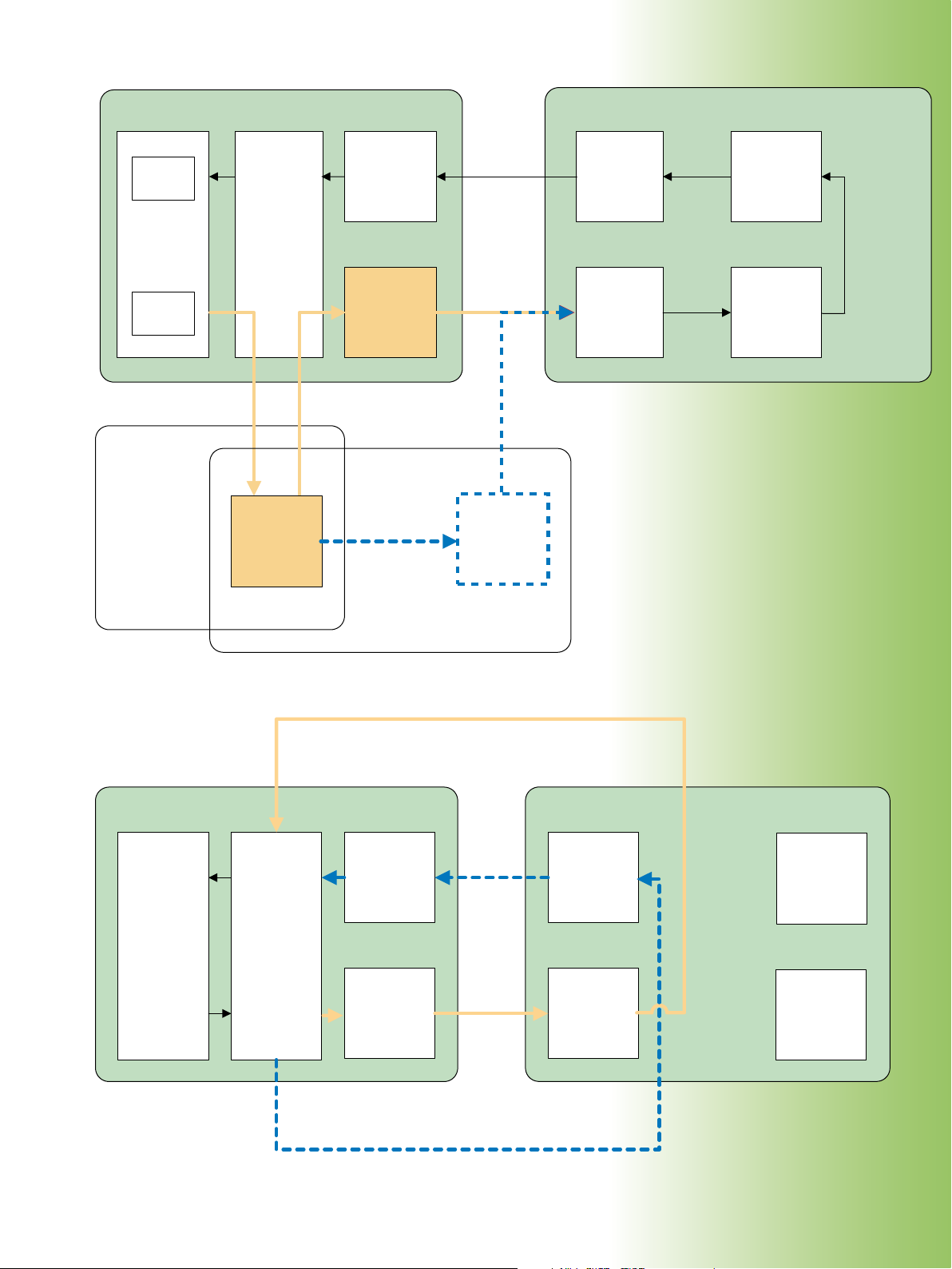
¸AMU200A
Fading Simulator
Radio modules
¸CMU200
Signaling unit
Transmitter
unit
Receiver
unit
¸CMU-B17
I/Q/IF
Interface
Faded
RF signal
¸SMU200A RF Generator
with option ¸SMU-B14
Fading Simulator
I/Q
Transmitter
RF module
Receiver
RF module
Transmitter
baseband
module
Receiver
baseband
module
Loop-back
for
GSM
BER tests
PN
generator
BER
analyzer
Fading
simulator
RF
transmitter
module
UL
DL
¸CMU200
Signaling unit
Radio modules
Transmitter
RF module
Receiver
RF module
Transmitter
baseband
module
Receiver
baseband
module
Transmitter
unit
Receiver
unit
¸CMU-B17
I/Q/IF
Interface
Test of RX parameters in ¸CMU200 non-signaling mode
Test of TX parameters in ¸CMU200 non-signaling mode
Analog I/Q
(baseband)
RF
I/Q IN
I/Q OUT
DL
UL
¸CMU200 Universal Radio Communication Tester 57

58 ¸CMU200 Universal Radio Communication Tester
¸CMU200 options and accessories
Type Description
GSM/GPRS/EDGE
TDMA
AMPS
CDMA2000® 1xRTT
CDMA2000® 1xEV-DO
WCDMA/HSPA
Bluetooth®
¸CMU200
¸CMU-B111)Reference OCXO, aging 2 × 10⁻⁷/year
¸CMU-B12
¸CMU-B17 Analog I/Q IF interface
¸CMU-B21
¸CMU-B21
¸CMU-B41 Audio generator and analyzer; includes audio frequency (AF) generator,
¸CMU-B52 Internal versatile multimode speech coder/decoder; ¸CMU-B21 necessary
¸CMU-B53 Bluetooth® extension; ¸CMU-B21 necessary
¸CMU-B55 HD option for (E)GPRS application testing with more than 2 UL slots
¸CMU-B56 WCDMA (3GPP FDD) signaling module for ¸CMU-B21 model 14
¸CMU-B68
¸CMU-B832)CDMA2000® 1xRTT signaling unit
¸CMU-B832)CDMA2000® 1xRTT signaling unit; required for CDMA2000® 1xEV-DO Rev. 0
¸CMU-B85 8 k/13 k QCELP, 8k EVRC speech codec for ¸CMU-B83 CDMA2000® 1xRTT
¸CMU-B85 8k/13k QCELP, 8k EVRC, EVRC-B speech codec for ¸CMU-B83 model 22
¸CMU-B87 Interface for extensive CDMA2000® 1xRTT /1xEV-DO data testing for
¸CMU-B883)CDMA2000® 1xEV-DO Rev. 0 and A non-signaling generator for
¸CMU-B893)CDMA2000® 1xEV-DO Rev. 0 and A signaling module for ¸CMU-B83 model 22
¸CMU-B95 Auxiliary generator that covers the requirements of present BCCH by GSM/
¸CMU-B96 2nd TX RF channel with full functionality; for generation of small-band signal
¸CMU-B99 RF1 level range identical to RF2
¸CMU-K14 Stereo FM transmitter
¸CMU-K16
¸CMU-K17 WCDMA (3GPP FDD) band 11, UE test signaling software
¸CMU-K20
¸CMU-K21
¸CMU-K22
¸CMU-K23
¸CMU-K24
¸CMU-K26
¸CMU-K27 IS-136/cellular (800 MHz band) mobile station signaling/non-signaling test
1)
¸CMU-B11 or ¸CMU -B12 possib le. One of two OCXOs should be inst alled to ensure high f requency accuracy, or an external frequency reference may b e used, if avai lable.
2)
Either ¸CMU -B83 model 12 or ¸CMU-B 83 model 22 is required.
3)
Either ¸CMU -B88 or ¸CMUB8 9 is required .
Base unit with following accessories: power cord, operating and service
manual for instrument
1)
High-stability OCXO, aging 3.5 × 10⁻⁸/year; oven crystal with highest longterm stability
Unversal signaling unit; provides multistandard signaling hardware;
required for WCDMA 3GPP FDD
Universal signaling unit; includes signaling module for AMPS, TDMA, GSM/
GPRS/EGPRS
voltmeter, distortion meter
Versatile baseband board for WCDMA (3GPP FDD) layer 1, DL and UL,
non-signaling
and A signaling
signaling unit
CDMA2000® 1xRTT signaling unit
CDMA2000® 1xRTT signaling unit ¸CMU-B83; requires ¸CMU-K87
¸CMU-B83 model 12 CDMA2000® 1xRTT signaling unit
CDMA2000® 1xRTT signaling unit
GPRS/EGPRS and application testing for (E)GPRS
(GSM BCCH, channel A) or of wideband signal (WCDMA BCCH, channel B)
WCDMA (3GPP FDD) band 10, UE test signaling software
(¸CMU-B68, ¸CMU-B21 model 14 or 54, ¸CMU-B56 necessary)
(¸CMU-B68, ¸CMU-B21 model 14 or 54, ¸CMU-B56 necessary)
GSM400 mobile station signaling/non-signaling test software
GSM900, R-GSM, and E-GSM mobile station signaling/non-signaling test
software
GSM1800 (DCS) mobile station signaling/non-signaling test software
GSM1900 (PCS) mobile station signaling/non-signaling test software
GSM850 mobile station signaling/non-signaling test software
GT800 mobile station signaling/non-signaling test software
software
þ þ þ þ þ þ þ
J J J J J J J
J J J J J J J
J J
þ þ þ
þ þ þ
–
J J J J
– –
– –
þ þ
þ þ
J J þ J J J J
J J
– – – – – –
J
J
– – – – –
– – –
– – –
– – –
– – –
– – –
– – –
– – –
J
J
– – –
J J
J
– – – – – – 1159.4000.14
– – – –
þ þ
þ þ
J J
J J
J J
J þ
J þ
– – – –
– – – –
– 1150.1850.14
þ
– 1149.9809.02
þ
– – 1150.0301.12
– – 1150.0301.22
– – 1100.7002.12
– – 1100.7002.22
– – 1150.2404.02
– – 1158.9908.02
– – 1159.3090.02
– 1159.0504.02
J
– 1159.1600.02
J
J J J J J J J
J J J J J J J
– – – – –
– – – – –
– – – – – – 1115.5900.02
ü
– – – – – – 1115.6007.02
ü
– – – – – – 1115.6107.02
ü
– – – – – – 1115.6207.02
ü
– – – – – – 1115.6307.02
ü
– – – – – – 1115.6507.02
ü
–
– – – – – 1115.6607.02
ü
– 1200.9158.02
ü
– 1200.9258.02
ü
Order No.
1100.0008.02
1100.5000.02
1100.5100.02
1100.6906.02
1100.5200.14
1100.5200.54
1100.5300.02
1100.5400.14
1100.5700.14
1150.1250.02
1200.7503.02

Type Description
¸CMU-K28 IS-136/PCS (1900 MHz band) mobile station signaling/non- signaling test
software
¸CMU-K29
¸CMU-K42
AMPS mobile station signaling/non-signaling test software
GPRS test software extension for all GSM test software packages
¸CMU-K43 EGPRS classic (EDGE) signaling test software for all GSM test software
packages
¸CMU-K44 Dual transfer mode: simultaneous CS and PS connection for all GSM packages
¸CMU-K45 AMR test software extension for all GSM test software packages
¸CMU-K46
Wideband adaptive multirate signaling for GSM and WCDMA
(GSM or WCDMA signaling option necessary)
¸CMU-K47 ¸Smart Alignment for all GSM and CDMA2000® packages
¸CMU-K48 I/Q versus slot measurement for adjustment of polar modulators
¸CMU-K53 Bluetooth® test software
¸CMU-K56
HSUPA 5.7 Mbit/s extension, 3GPP/FDD/UE, Rel.6
(¸CMU-B68, ¸CMU-B21 model 14 or 54, ¸CMU-B56 necessary)
¸CMU-K57 WCDMA signaling 3GPP/FDD/UE, band 7
(¸CMU-B68, ¸CMU-B21 model 14 or 54, ¸CMU-B56 necessary)
¸CMU-K58 WCDMA signaling 3GPP/FDD/UE, band 8
(¸CMU-B68, ¸CMU-B21 model 14 or 54, ¸CMU-B56 necessary)
¸CMU-K59 WCDMA signaling 3GPP/FDD/UE, band 9
(¸CMU-B68, ¸CMU-B21 model 14 or 54, ¸CMU-B56 necessary)
¸CMU-K60
¸CMU-K61
¸CMU-K62
HSDPA 14 Mbit/s extension 3GPP/FDD/UE, Rel. 5 (¸CMU-K64 necessary)
WCDMA (3GPP FDD) band 4, UE test signaling software
WCDMA (3GPP FDD) band 5, UE test signaling software
¸CMU-K63 WCDMA (3GPP FDD) band 6, UE test signaling software
¸CMU-K64 3.6 Mbit/s HSDPA
¸CMU-K65
¸CMU-K66
¸CMU-K67
¸CMU-K68
WCDMA (3GPP FDD) UL user equipment TX test, non-signaling test software
WCDMA (3GPP FDD) DL generator, non-signaling test software
WCDMA (3GPP FDD) band 3, UE test signaling software
WCDMA (3GPP FDD) band 1, UE test signaling software
¸CMU-K69 WCDMA (3GPP FDD) band 2, UE test signaling software
¸CMU-K83 CDMA2000® 1xRTT 450 MHz bands (band class 5, 11) test software
¸CMU-K84 CDMA2000® 1xRTT cellular bands (band class 0, 2, 3, 7, 9, 10, 12) test
software
¸CMU-K85 CDMA2000® 1xRTT PCS bands (band class 1, 4, 8, 14) test software
¸CMU-K86 CDMA2000® 1xRTT IMT-2000 bands (band class 6, 13, 15, 16, 17) test software
¸CMU-K87 Extensive CDMA2000® 1xRTT/1xEV-DO data testing; requires ¸CMU-B87
¸CMU-K88 CDMA2000® 1x EV-DO Rev. 0 and A non-signaling test software package for
¸CMU-B88, including 450 MHz + cellular + PCS + IMT-2000 bands
¸CMU-K92 (E)GPRS application testing; external PC, Windows XP/2000, GPRS or EGPRS
software option, and ¸CMU-B95 auxiliary generator plus power PC
required
¸CMU-K96
WCDMA application testing; at least one WCDMA signaling band necessary
¸CMU-K839 CDMA2000® 1xEV-DO 450 MHz bands (band class 5, 11) test software for
¸CMU-B89
R&S CMU-K849 CDMA2000® 1xEV-DO Cellular bands (band class 0, 2, 3, 7, 9, 10, 12) test
software for ¸CMU-B89
R&S CMU-K859 CDMA2000® 1xEV-DO PCS bands (band class 1, 4, 8, 14) test software for
¸CMU-B89
R&S CMU-K869 CDMA2000® 1xEV-DO IMT-2000 bands (band class 6, 13, 15, 16, 17) test
software for ¸CMU-B89
GSM/GPRS/EDGE
TDMA
AMPS
CDMA2000® 1xRTT
CDMA2000® 1xEV-DO
WCDMA/HSPA
–
– –
J
J
J
J
J
J
J
– – – – – –
– – – – –
– – – – –
– – – – –
– – – – –
– – – – –
– – – – –
– – – – –
– – – – –
– – – – –
– – – – –
– – – – –
– – – – –
– – – – –
– – – – –
– – –
– – –
– – –
– – –
– – –
– – –
J
– – – – –
– – –
– – –
– – –
– – –
– – – – – 1115.6707.02
ü
– – – – 1115.6807.02
þ
– – – – – – 1115.4691.02
– – – – – – 1115.6907.02
– – – – – – 1157.4277.02
– – – – – – 1150.3100.02
– – – –
– –
J J
– 1200.8800.02
J
– – 1157.4477.02
– – – – – – 1157.5309.02
þ
– 1200.7803.02
J
– 1200.7903.02
ü
– 1200.8000.02
ü
– 1200.8100.02
ü
– 1200.8200.02
J
– 1157.3670.02
ü
– 1157.3770.02
ü
– 1157.3870.02
ü
– 1157.3970.02
J
– 1115.4891.02
þ
– 1115.5100.02
þ
– 1150.3000.02
ü
– 1115.5300.02
ü
– 1115.5400.02
ü
– – – 1150.3500.02
ü
– – – 1150.3600.02
ü
– – – 1150.3700.02
ü
– – – 1150.3800.02
ü
J J
J J
– – 1150.4007.02
– – 1150.3900.02
– – – – – – 1157.4077.02
– 1157.4177.02
J
J ü
J ü
J ü
J ü
– – 1200.8300.02
– – 1200.8400.02
– – 1200.8500.02
– – 1200.8600.02
Order No.
Bluetooth®
1115.5000.02
¸CMU200 Universal Radio Communication Tester 59

Type Description
¸CMU-PK204)Software package for ¸CMU200 including GSM850 + 900 + 1800 + 1900
+ GPRS signaling (¸CMU-K21, -K22, -K23, -K24, -K42)
4)
¸CMU-PK60
Software package for ¸CMU200 including WCDMA signaling: 3GPP/FDD/
UE, TX test, DL generator, band 1+2+3+4+5+6
(¸CMU-K61, -K62, -K63, -K65, -K66, -K67, -K68, -K69)
¸CMU-PK804)Software package for ¸CMU200 including CDMA2000® bands 450 MHz +
PCS + cellular + IMT-2000; analog AMPS
(¸CMU-K83, -K84, -K85, -K86, -K29)
¸CMU-PK1004)Software package for ¸CMU200 including GSM/GPRS/EGPRS + WCDMA
+ CDMA2000® 1xRTT + 1xEV-DO + AMPS + IS-136
(¸CMU-PK20, -PK60, -PK80, -PK800, -K27, -K28, -K43, -K88)
¸CMU-PK800 Software package for ¸CMU200 including CDMA2000® 1x EV-DO Rev. 0
and A for 450 MHz + cellular+ PCS + IMT-2000 bands
(¸CMU-K839, -K849, -K859, -K869)
¸CMU-U80 Low jitter trigger output connector (for A-GPS)
¸CMU-Z1 256 Mbyte memory card for use with PCMCIA interface;
flash ATA formatted, also named PC Card ATA
¸CMU-Z6
Enhancement of wideband modulation (WCDMA 3GPP FDD) analyzer accuracy
¸CMU-Z10 Antenna coupler 900 MHz/1700 MHz to 2200 MHz
¸CMU-Z11 RF shielded cover, extension for ¸CMU-Z10
¸CMU-Z12
Bluetooth® antenna, extension for ¸CMU-Z10
¸CMU-Z13 USB 2.0 feedthrough for ¸CMU-Z10
¸CMU-Z46
WCDMA (3GPP FDD) message analyzer and recorder
¸CMU-Z50 Handset for ¸CMU200
¸CMU-Z89 Hybrid mode test kit; for connecting two ¸CMU200 for CDMA2000® 1xRTT
and 1xEV-DO hybrid mode applications
¸CMU-DCV Documentation of calibration values
¸CRT-Z2
GSM/GPRS test SIM for GSM900 and DCS1800 for loopback mode;
required for BER and other applications
¸CRT-Z12
GSM/GPRS test SIM for GSM850 and PCS1900 for loopback mode;
required for BER and other applications
¸CRT-Z3 3G UICC/USIM test card for UMTS
¸ZZA-411 19” rack adapter
GSM/GPRS/EDGE
TDMA
AMPS
CDMA2000® 1xRTT
CDMA2000® 1xEV-DO
WCDMA/HSPA
– – – – – – 1159.3303.04
J
– – – – –
– –
J J
– – – 1159.3403.02
J J J J J J
– – – –
– – –
J
J J
– 1159.3355.04
J
– 1159.3455.06
– – 1200.0609.02
– – 1150.1750.02
J J J J J J J
– – – – –
– 1150.0001.02
J
J J J J J J J
J J J J J J J
– –
J
J J J J
J J J J J J J
– – – – –
– 1159.0804.02
J
J J J J J J J
– – –
J J
– – 1200.0750.02
J J J J J J J
– – – – – – 1039.9005.02
J
– – – – – – 1139.1205.02
J
– – – – –
– 1139.1005.02
J
J J J J J J J
Order No.
Bluetooth®
1100.7490.04
1150.0801.10
1150.1008.02
1150.1043.02
1159.1200.20
1159.0104.02
0240.2193.08
1069.3283.00
Comments on table
þ mandatory
ü signaling option (at least one is mandatory)
J optional
– not applicable
4)
When ordering one of t he ¸CMU-PK20 t o -PK100 sof tware pa ckages, th e signaling so ftware in cluded in the se package s does not have t o be ordered s eparatel y.
¸CMU200 Universal Radio Communication Tester 60

Value-added services
Rohde & Schwarz offers a wide range of training programs not only on products but also on new technical developments
◆
Rohde & Schwarz application engineers help to optimize the use of the ¸CMU200 and the overall performance of your local
◆
environment
Over 70 representative offices and a worldwide network of service and calibration centers ensure Rohde & Schwarz support
◆
where you need it
Quality management at Rohde & Schwarz
Lasting customer satisfaction is our primary objective. The quality management system of Rohde & Schwarz meets the requirements
of ISO 9001 and encompasses virtually all fields of activity of the company.
¸CMU200 Universal Radio Communication Tester 61

Certified Quality System
ISO 9001
DQS REG. NO 1954 QM
Certified Environmental System
ISO
14001
DQS REG. NO 1954 UM
For data sheet, see PD 0758.0039.22
Certified Quality System
ISO 9001
DQS REG. NO 1954 QM
Certified Environmental System
ISO
14001
DQS REG. NO 1954 UM
and www.rohde-schwarz.com
(search term: CMU200)
· Data without tolerance limits is not binding · Subject to change
¸is a registered trademark of Rohde & Schwarz GmbH & Co. KG · Trade names are trademarks of the owners · Printed in Germany (as)
PD 0758.0039.12 · ¸CMU200 · Version 09.00 · November 2007
Europe: +49 1805 12 4242, customersupport@rohde-schwarz.com
www.rohde-schwarz.com
Americas: 1-888-837-8772, customer.support@rsa.rohde-schwarz.com
Asia: +65 65130488, customersupport.asia@rohde-schwarz.com
 Loading...