


User Manual
CMD 80
Digital Radiocommunication Tester
070-9230-08
This document applies to firmware version 3.3
and above.
www.tektronix.com

Copyright © T ektronix, Inc. All rights reserved.
T ektronix products are covered by U.S. and foreign patents, issued and pending. Information in this publication supercedes
that in all previously published material. Specifications and price change privileges reserved.
T ektronix, Inc., P.O. Box 500, Beaverton, OR 97077
TEKTRONIX and TEK are registered trademarks of T ektronix, Inc.

WARRANTY
T ektronix warrants that the products that it manufactures and sells will be free from defects in materials and workmanship
for a period of one (1) year from the date of shipment. If a product proves defective during this warranty period, T ektronix,
at its option, either will repair the defective product without charge for parts and labor, or will provide a replacement in
exchange for the defective product.
In order to obtain service under this warranty, Customer must notify Tektronix of the defect before the expiration of the
warranty period and make suitable arrangements for the performance of service. Customer shall be responsible for
packaging and shipping the defective product to the service center designated by T ektronix, with shipping charges prepaid.
T ektronix shall pay for the return of the product to Customer if the shipment is to a location within the country in which the
T ektronix service center is located. Customer shall be responsible for paying all shipping charges, duties, taxes, and any
other charges for products returned to any other locations.
This warranty shall not apply to any defect, failure or damage caused by improper use or improper or inadequate
maintenance and care. T ektronix shall not be obligated to furnish service under this warranty a) to repair damage resulting
from attempts by personnel other than T ektronix representatives to install, repair or service the product; b) to repair
damage resulting from improper use or connection to incompatible equipment; c) to repair any damage or malfunction
caused by the use of non-T ektronix supplies; or d) to service a product that has been modified or integrated with other
products when the effect of such modification or integration increases the time or difficulty of servicing the product.
THIS WARRANTY IS GIVEN BY TEKTRONIX IN LIEU OF ANY OTHER WARRANTIES, EXPRESS OR
IMPLIED. TEKTRONIX AND ITS VENDORS DISCLAIM ANY IMPLIED WARRANTIES OF
MERCHANTABILITY OR FITNESS FOR A PARTICULAR PURPOSE. TEKTRONIX’ RESPONSIBILITY TO
REP AIR OR REPLACE DEFECTIVE PRODUCTS IS THE SOLE AND EXCLUSIVE REMEDY PROVIDED TO
THE CUSTOMER FOR BREACH OF THIS WARRANTY. TEKTRONIX AND ITS VENDORS WILL NOT BE
LIABLE FOR ANY INDIRECT , SPECIAL, INCIDENTAL, OR CONSEQUENTIAL DAMAGES IRRESPECTIVE
OF WHETHER TEKTRONIX OR THE VENDOR HAS ADVANCE NOTICE OF THE POSSIBILITY OF SUCH
DAMAGES.


Table of Contents
Getting Started
Operating Basics
General Safety Summary xix. . . . . . . . . . . . . . . . . . . . . . . . . . . . . . . . . . . .
Preface xxi. . . . . . . . . . . . . . . . . . . . . . . . . . . . . . . . . . . . . . . . . . . . . . . . . . .
Getting Started 1–1. . . . . . . . . . . . . . . . . . . . . . . . . . . . . . . . . . . . . . . . . . . .
Product Description 1–1. . . . . . . . . . . . . . . . . . . . . . . . . . . . . . . . . . . . . . . . . . . . . . .
First Time Operation 1–3. . . . . . . . . . . . . . . . . . . . . . . . . . . . . . . . . . . . . . . . . . . . . .
Power Connection 1–3. . . . . . . . . . . . . . . . . . . . . . . . . . . . . . . . . . . . . . . . . . . . .
Functional Checks 1–4. . . . . . . . . . . . . . . . . . . . . . . . . . . . . . . . . . . . . . . . . . . . . . . .
Connect the Mobile Station 1–4. . . . . . . . . . . . . . . . . . . . . . . . . . . . . . . . . . . . .
CDMA Functional Check 1–5. . . . . . . . . . . . . . . . . . . . . . . . . . . . . . . . . . . . . . .
Analog Functional Check (Option B82 Only) 1–8. . . . . . . . . . . . . . . . . . . . . . .
TDMA Functional Check (Option B84 Only) 1–11. . . . . . . . . . . . . . . . . . . . . . .
General Configuration 1–14. . . . . . . . . . . . . . . . . . . . . . . . . . . . . . . . . . . . . . . . . . . . .
REFERENCE/TIMING 1–15. . . . . . . . . . . . . . . . . . . . . . . . . . . . . . . . . . . . . . . .
RF CONNECT/EXT ATTEN 1–16. . . . . . . . . . . . . . . . . . . . . . . . . . . . . . . . . . . .
GPIB/IEC ADDRESS 1–18. . . . . . . . . . . . . . . . . . . . . . . . . . . . . . . . . . . . . . . . . .
PRINTER 1–18. . . . . . . . . . . . . . . . . . . . . . . . . . . . . . . . . . . . . . . . . . . . . . . . . . .
OTHER 1–19. . . . . . . . . . . . . . . . . . . . . . . . . . . . . . . . . . . . . . . . . . . . . . . . . . . . .
Reference
Operating Basics 2–1. . . . . . . . . . . . . . . . . . . . . . . . . . . . . . . . . . . . . . . . . . .
Front-Panel Display, Controls, and Connectors 2–1. . . . . . . . . . . . . . . . . . . . . . . . . .
Softkeys 2–2. . . . . . . . . . . . . . . . . . . . . . . . . . . . . . . . . . . . . . . . . . . . . . . . . . . . .
Display Area 2–2. . . . . . . . . . . . . . . . . . . . . . . . . . . . . . . . . . . . . . . . . . . . . . . . .
Data Keypad 2–3. . . . . . . . . . . . . . . . . . . . . . . . . . . . . . . . . . . . . . . . . . . . . . . . .
Memory Card, Hardkey, and Loudspeaker Area 2–5. . . . . . . . . . . . . . . . . . . . .
Front-Panel Controls and Connectors 2–7. . . . . . . . . . . . . . . . . . . . . . . . . . . . . .
Rear-Panel Controls and Connectors 2–8. . . . . . . . . . . . . . . . . . . . . . . . . . . . . . . . . .
Menu Structures 2–9. . . . . . . . . . . . . . . . . . . . . . . . . . . . . . . . . . . . . . . . . . . . . . . . . .
Reference 3–1. . . . . . . . . . . . . . . . . . . . . . . . . . . . . . . . . . . . . . . . . . . . . . . . .
Network, System, and Standard
Network, System, and Standard 3–3. . . . . . . . . . . . . . . . . . . . . . . . . . . . . .
Network 3–3. . . . . . . . . . . . . . . . . . . . . . . . . . . . . . . . . . . . . . . . . . . . . . . . . . . . . . . .
System 3–4. . . . . . . . . . . . . . . . . . . . . . . . . . . . . . . . . . . . . . . . . . . . . . . . . . . . . . . . .
Standard 3–4. . . . . . . . . . . . . . . . . . . . . . . . . . . . . . . . . . . . . . . . . . . . . . . . . . . . . . . .
CDMA Measurements
CDMA 3–5. . . . . . . . . . . . . . . . . . . . . . . . . . . . . . . . . . . . . . . . . . . . . . . . . . . .
Using the Home Menu 3–5. . . . . . . . . . . . . . . . . . . . . . . . . . . . . . . . . . . . . . . . . . . . .
Manual T est (Signaling) 3–7. . . . . . . . . . . . . . . . . . . . . . . . . . . . . . . . . . . . . . . . . . . .
MS Unregistered 3–7. . . . . . . . . . . . . . . . . . . . . . . . . . . . . . . . . . . . . . . . . . . . . .
CMD 80 Digital Radiocommunication Tester User Manual
i

Table of Contents
MS Registered 3–1 1. . . . . . . . . . . . . . . . . . . . . . . . . . . . . . . . . . . . . . . . . . . . . . . .
Call to Mobile (Voice Loopback) 3–13. . . . . . . . . . . . . . . . . . . . . . . . . . . . . . . . .
Call to Mobile (MS T ests) 3–15. . . . . . . . . . . . . . . . . . . . . . . . . . . . . . . . . . . . . . .
Additional Measurement 3–16. . . . . . . . . . . . . . . . . . . . . . . . . . . . . . . . . . . . . . . .
Power Control 3–16. . . . . . . . . . . . . . . . . . . . . . . . . . . . . . . . . . . . . . . . . . . . . . . .
Receiver Quality 3–21. . . . . . . . . . . . . . . . . . . . . . . . . . . . . . . . . . . . . . . . . . . . . .
Transmitter Quality 3–26. . . . . . . . . . . . . . . . . . . . . . . . . . . . . . . . . . . . . . . . . . . .
Multiple Pilots 3–28. . . . . . . . . . . . . . . . . . . . . . . . . . . . . . . . . . . . . . . . . . . . . . . .
Softer Handoff 3–30. . . . . . . . . . . . . . . . . . . . . . . . . . . . . . . . . . . . . . . . . . . . . . .
Handoffs/Transitions 3–33. . . . . . . . . . . . . . . . . . . . . . . . . . . . . . . . . . . . . . . . . . .
BS Signal Cnfg 3–35. . . . . . . . . . . . . . . . . . . . . . . . . . . . . . . . . . . . . . . . . . . . . . .
T otal Power 3–36. . . . . . . . . . . . . . . . . . . . . . . . . . . . . . . . . . . . . . . . . . . . . . . . . .
RF Channel 3–36. . . . . . . . . . . . . . . . . . . . . . . . . . . . . . . . . . . . . . . . . . . . . . . . . .
Traffic Channel 3–36. . . . . . . . . . . . . . . . . . . . . . . . . . . . . . . . . . . . . . . . . . . . . . .
Frame Offset 3–37. . . . . . . . . . . . . . . . . . . . . . . . . . . . . . . . . . . . . . . . . . . . . . . . .
PN Offset 3–37. . . . . . . . . . . . . . . . . . . . . . . . . . . . . . . . . . . . . . . . . . . . . . . . . . .
Call Established configuration menu 3–37. . . . . . . . . . . . . . . . . . . . . . . . . . . . . .
Module T est 3–42. . . . . . . . . . . . . . . . . . . . . . . . . . . . . . . . . . . . . . . . . . . . . . . . . . . . .
Additional Measurement 3–43. . . . . . . . . . . . . . . . . . . . . . . . . . . . . . . . . . . . . . . .
MS Power Expected 3–43. . . . . . . . . . . . . . . . . . . . . . . . . . . . . . . . . . . . . . . . . . .
MS Power Control 3–43. . . . . . . . . . . . . . . . . . . . . . . . . . . . . . . . . . . . . . . . . . . .
Transmitter Quality 3–43. . . . . . . . . . . . . . . . . . . . . . . . . . . . . . . . . . . . . . . . . . . .
BS RF Channel 3–43. . . . . . . . . . . . . . . . . . . . . . . . . . . . . . . . . . . . . . . . . . . . . . .
Nominal BS T otal Power 3–43. . . . . . . . . . . . . . . . . . . . . . . . . . . . . . . . . . . . . . .
Traffic Level 3–43. . . . . . . . . . . . . . . . . . . . . . . . . . . . . . . . . . . . . . . . . . . . . . . . .
Paging Level 3–44. . . . . . . . . . . . . . . . . . . . . . . . . . . . . . . . . . . . . . . . . . . . . . . . .
Sync Level 3–44. . . . . . . . . . . . . . . . . . . . . . . . . . . . . . . . . . . . . . . . . . . . . . . . . .
Pilot Level 3–44. . . . . . . . . . . . . . . . . . . . . . . . . . . . . . . . . . . . . . . . . . . . . . . . . . .
OCNS 3–44. . . . . . . . . . . . . . . . . . . . . . . . . . . . . . . . . . . . . . . . . . . . . . . . . . . . . .
AWGN Level 3–44. . . . . . . . . . . . . . . . . . . . . . . . . . . . . . . . . . . . . . . . . . . . . . . .
Module T est Configuration Menu 3–45. . . . . . . . . . . . . . . . . . . . . . . . . . . . . . . . .
Configuration 3–48. . . . . . . . . . . . . . . . . . . . . . . . . . . . . . . . . . . . . . . . . . . . . . . . . . . .
Manual T est 3–49. . . . . . . . . . . . . . . . . . . . . . . . . . . . . . . . . . . . . . . . . . . . . . . . . .
Module T est 3–49. . . . . . . . . . . . . . . . . . . . . . . . . . . . . . . . . . . . . . . . . . . . . . . . .
CDMA BS Signal Cnfg 3–49. . . . . . . . . . . . . . . . . . . . . . . . . . . . . . . . . . . . . . . .
Protocol Revision 3–49. . . . . . . . . . . . . . . . . . . . . . . . . . . . . . . . . . . . . . . . . . . . .
Mobile ID T ype 3–49. . . . . . . . . . . . . . . . . . . . . . . . . . . . . . . . . . . . . . . . . . . . . . .
Analog Measurements (Option B82 Only)
Analog 3–51. . . . . . . . . . . . . . . . . . . . . . . . . . . . . . . . . . . . . . . . . . . . . . . . . . . .
Using the Home Menu 3–51. . . . . . . . . . . . . . . . . . . . . . . . . . . . . . . . . . . . . . . . . . . . .
About the menu displays 3–52. . . . . . . . . . . . . . . . . . . . . . . . . . . . . . . . . . .
Manual Test (Signaling) 3–54. . . . . . . . . . . . . . . . . . . . . . . . . . . . . . . . . . . . . . . . . . . .
MS Unregistered 3–54. . . . . . . . . . . . . . . . . . . . . . . . . . . . . . . . . . . . . . . . .
MS Registered 3–61. . . . . . . . . . . . . . . . . . . . . . . . . . . . . . . . . . . . . . . . . . .
Call Established 3–63. . . . . . . . . . . . . . . . . . . . . . . . . . . . . . . . . . . . . . . . .
Call Established (MS Tests) Menu Selections 3–73. . . . . . . . . . . . . . . . . . . . . . . . . . .
Additional Measurement 3–73. . . . . . . . . . . . . . . . . . . . . . . . . . . . . . . . . . .
Carrier Power 3–73. . . . . . . . . . . . . . . . . . . . . . . . . . . . . . . . . . . . . . . . . . .
Receiver Quality 3–74. . . . . . . . . . . . . . . . . . . . . . . . . . . . . . . . . . . . . . . . .
Transmitter Quality 3–82. . . . . . . . . . . . . . . . . . . . . . . . . . . . . . . . . . . . . . .
Handoffs/Transitions 3–91. . . . . . . . . . . . . . . . . . . . . . . . . . . . . . . . . . . . . .
BS Signal Configuration 3–93. . . . . . . . . . . . . . . . . . . . . . . . . . . . . . . . . . .
ii
CMD 80 Digital Radiocommunication Tester User Manual

Module Test 3–96. . . . . . . . . . . . . . . . . . . . . . . . . . . . . . . . . . . . . . . . . . . . . . . . . . . . .
Additional Measurement 3–103. . . . . . . . . . . . . . . . . . . . . . . . . . . . . . . . . . .
Carrier Power 3–104. . . . . . . . . . . . . . . . . . . . . . . . . . . . . . . . . . . . . . . . . . .
Receiver Quality 3–104. . . . . . . . . . . . . . . . . . . . . . . . . . . . . . . . . . . . . . . . .
Transmitter Quality 3–111. . . . . . . . . . . . . . . . . . . . . . . . . . . . . . . . . . . . . . .
Configuration 3–117. . . . . . . . . . . . . . . . . . . . . . . . . . . . . . . . . . . . . . . . . . . . . . . . . . . .
Manual Test 3–118. . . . . . . . . . . . . . . . . . . . . . . . . . . . . . . . . . . . . . . . . . . . .
Module Test 3–140. . . . . . . . . . . . . . . . . . . . . . . . . . . . . . . . . . . . . . . . . . . .
ANALOG BS Signal CNFG 3–160. . . . . . . . . . . . . . . . . . . . . . . . . . . . . . . .
TDMA Measurements (Option B84 Only)
TDMA 3–167. . . . . . . . . . . . . . . . . . . . . . . . . . . . . . . . . . . . . . . . . . . . . . . . . . . .
Using the Home Menu 3–167. . . . . . . . . . . . . . . . . . . . . . . . . . . . . . . . . . . . . . . . . . . . .
About the menu displays 3–168. . . . . . . . . . . . . . . . . . . . . . . . . . . . . . . . . . .
Manual Test 3–171. . . . . . . . . . . . . . . . . . . . . . . . . . . . . . . . . . . . . . . . . . . . . . . . . . . . .
MS Unregistered State 3–172. . . . . . . . . . . . . . . . . . . . . . . . . . . . . . . . . . . .
MS Registered State 3–175. . . . . . . . . . . . . . . . . . . . . . . . . . . . . . . . . . . . . .
Call Established 3–179. . . . . . . . . . . . . . . . . . . . . . . . . . . . . . . . . . . . . . . . .
Call Established (MS Tests) Selections 3–185. . . . . . . . . . . . . . . . . . . . . . . . . . . . . . . .
Additional Measurement 3–185. . . . . . . . . . . . . . . . . . . . . . . . . . . . . . . . . . .
Receiver Quality 3–185. . . . . . . . . . . . . . . . . . . . . . . . . . . . . . . . . . . . . . . . .
Transmitter Quality 3–194. . . . . . . . . . . . . . . . . . . . . . . . . . . . . . . . . . . . . . .
Time Alignment 3–208. . . . . . . . . . . . . . . . . . . . . . . . . . . . . . . . . . . . . . . . . . .
Handoffs/Transitions 3–211. . . . . . . . . . . . . . . . . . . . . . . . . . . . . . . . . . . . . .
BS Signal Configuration (Call Established) 3–213. . . . . . . . . . . . . . . . . . . .
Module Test 3–215. . . . . . . . . . . . . . . . . . . . . . . . . . . . . . . . . . . . . . . . . . . . . . . . . . . . .
Additional Measurement 3–218. . . . . . . . . . . . . . . . . . . . . . . . . . . . . . . . . . .
Receiver Quality 3–218. . . . . . . . . . . . . . . . . . . . . . . . . . . . . . . . . . . . . . . . .
Transmitter Quality 3–222. . . . . . . . . . . . . . . . . . . . . . . . . . . . . . . . . . . . . . .
Configuration 3–229. . . . . . . . . . . . . . . . . . . . . . . . . . . . . . . . . . . . . . . . . . . . . . . . . . . .
Manual Test 3–230. . . . . . . . . . . . . . . . . . . . . . . . . . . . . . . . . . . . . . . . . . . . .
Module Test 3–243. . . . . . . . . . . . . . . . . . . . . . . . . . . . . . . . . . . . . . . . . . . .
TDMA BS SIGNAL CNFG 3–251. . . . . . . . . . . . . . . . . . . . . . . . . . . . . . . .
Table of Contents
Additional Measurements
Additional Measurements 3–255. . . . . . . . . . . . . . . . . . . . . . . . . . . . . . . . . . . .
Audio Measurements
Audio Measurements 3–257. . . . . . . . . . . . . . . . . . . . . . . . . . . . . . . . . . . . . . . .
Fundamental Frequency 3–258. . . . . . . . . . . . . . . . . . . . . . . . . . . . . . . . . . . . . . . . . . . .
Harmonic Distortion 3–259. . . . . . . . . . . . . . . . . . . . . . . . . . . . . . . . . . . . . . . . . . . . . . .
Appendices
Appendix A: Specifications A–1. . . . . . . . . . . . . . . . . . . . . . . . . . . . . . . . . . .
Appendix B: Channel to Frequency Conversion Formulas B–1. . . . . . . .
Appendix C: FM/AF Measurement Filters C–1. . . . . . . . . . . . . . . . . . . . . .
Appendix D: Remote Control D–1. . . . . . . . . . . . . . . . . . . . . . . . . . . . . . . . .
Setting the Device Address D–3. . . . . . . . . . . . . . . . . . . . . . . . . . . . . . . . . . . . . . . . .
Serial Interface D–3. . . . . . . . . . . . . . . . . . . . . . . . . . . . . . . . . . . . . . . . . . . . . . . . . . .
CMD 80 Digital Radiocommunication Tester User Manual
iii

Table of Contents
Interface Characteristics D–4. . . . . . . . . . . . . . . . . . . . . . . . . . . . . . . . . . . . . . . .
Data Lines D–5. . . . . . . . . . . . . . . . . . . . . . . . . . . . . . . . . . . . . . . . . . . . . . . . . . .
Control Lines D–5. . . . . . . . . . . . . . . . . . . . . . . . . . . . . . . . . . . . . . . . . . . . . . . .
Default Settings D–5. . . . . . . . . . . . . . . . . . . . . . . . . . . . . . . . . . . . . . . . . . . . . . .
Handshake D–6. . . . . . . . . . . . . . . . . . . . . . . . . . . . . . . . . . . . . . . . . . . . . . . . . . .
Local/Remote Switchover D–8. . . . . . . . . . . . . . . . . . . . . . . . . . . . . . . . . . . . . . . . . .
Interface Messages D–8. . . . . . . . . . . . . . . . . . . . . . . . . . . . . . . . . . . . . . . . . . . . . . . .
Universal Commands (GPIB only) D–8. . . . . . . . . . . . . . . . . . . . . . . . . . . . . . . .
Addressed Commands (GPIB only) D–10. . . . . . . . . . . . . . . . . . . . . . . . . . . . . . .
Commands Received by the tester in Listen Mode (Controller to
Device Messages) D–10. . . . . . . . . . . . . . . . . . . . . . . . . . . . . . . . . . . . . .
Messages Sent by the tester in T alker Mode (Device to Controller
Messages) D–14. . . . . . . . . . . . . . . . . . . . . . . . . . . . . . . . . . . . . . . . . . . .
Device Independent (Common) Commands D–16. . . . . . . . . . . . . . . . . . . . . . . . .
Device-Specific Commands D–16. . . . . . . . . . . . . . . . . . . . . . . . . . . . . . . . . . . . .
Service Request and Status Registers D–16. . . . . . . . . . . . . . . . . . . . . . . . . . . . . . . . .
Resetting the Device Functions D–21. . . . . . . . . . . . . . . . . . . . . . . . . . . . . . . . . . . . . .
Command Processing Sequence and Synchronization D–22. . . . . . . . . . . . . . . . . . . .
OPERATION COMPLETE Command D–22. . . . . . . . . . . . . . . . . . . . . . . . . . . .
WAIT Command D–22. . . . . . . . . . . . . . . . . . . . . . . . . . . . . . . . . . . . . . . . . . . . . .
Error Handling D–22. . . . . . . . . . . . . . . . . . . . . . . . . . . . . . . . . . . . . . . . . . . . . . . . . . .
Appendix E: Remote Control Commands E–1. . . . . . . . . . . . . . . . . . . . . .
Command Set Organization E–1. . . . . . . . . . . . . . . . . . . . . . . . . . . . . . . . . . . . . . . . .
Instrument Model E–3. . . . . . . . . . . . . . . . . . . . . . . . . . . . . . . . . . . . . . . . . . . . . . . . .
State-Based Operation E–3. . . . . . . . . . . . . . . . . . . . . . . . . . . . . . . . . . . . . . . . . . . . .
Changing States E–7. . . . . . . . . . . . . . . . . . . . . . . . . . . . . . . . . . . . . . . . . . . . . .
Non-Allowed Commands E–9. . . . . . . . . . . . . . . . . . . . . . . . . . . . . . . . . . . . . . .
Non-Allowed Queries E–9. . . . . . . . . . . . . . . . . . . . . . . . . . . . . . . . . . . . . . . . . .
Unplanned State Changes E–9. . . . . . . . . . . . . . . . . . . . . . . . . . . . . . . . . . . . . . .
Command Descriptions E–10. . . . . . . . . . . . . . . . . . . . . . . . . . . . . . . . . . . . . . . . . . . .
Common Commands E–10. . . . . . . . . . . . . . . . . . . . . . . . . . . . . . . . . . . . . . . . . .
Status Reporting Commands and Queries E–11. . . . . . . . . . . . . . . . . . . . . . . . . .
Settings Store and Recall E–12. . . . . . . . . . . . . . . . . . . . . . . . . . . . . . . . . . . . . . .
External Signal Configuration E–13. . . . . . . . . . . . . . . . . . . . . . . . . . . . . . . . . . .
Miscellaneous Commands E–14. . . . . . . . . . . . . . . . . . . . . . . . . . . . . . . . . . . . . .
Base Station Configuration E–14. . . . . . . . . . . . . . . . . . . . . . . . . . . . . . . . . . . . . .
RF Source Control E–21. . . . . . . . . . . . . . . . . . . . . . . . . . . . . . . . . . . . . . . . . . . .
Information in the Registered State E–22. . . . . . . . . . . . . . . . . . . . . . . . . . . . . . .
Establishing a Call E–23. . . . . . . . . . . . . . . . . . . . . . . . . . . . . . . . . . . . . . . . . . . .
Information in Call Established State E–26. . . . . . . . . . . . . . . . . . . . . . . . . . . . . .
Receiver Quality T ests E–27. . . . . . . . . . . . . . . . . . . . . . . . . . . . . . . . . . . . . . . . .
Open Loop Time Response Test (Power Control) E–35. . . . . . . . . . . . . . . . . . . .
Gated Output T est (Power Control) E–37. . . . . . . . . . . . . . . . . . . . . . . . . . . . . . .
Maximum Output T est (Power Control) E–40. . . . . . . . . . . . . . . . . . . . . . . . . . . .
Minimum Output T est (Power Control) E–42. . . . . . . . . . . . . . . . . . . . . . . . . . . .
Transmitter Quality Test E–43. . . . . . . . . . . . . . . . . . . . . . . . . . . . . . . . . . . . . . . .
Handoffs E–52. . . . . . . . . . . . . . . . . . . . . . . . . . . . . . . . . . . . . . . . . . . . . . . . . . . .
Local Transitions E–57. . . . . . . . . . . . . . . . . . . . . . . . . . . . . . . . . . . . . . . . . . . . . .
Power Level Maintenance E–58. . . . . . . . . . . . . . . . . . . . . . . . . . . . . . . . . . . . . . .
Appendix F: Remote Control Command Tables F–1. . . . . . . . . . . . . . . . .
Remote Command Groups F–1. . . . . . . . . . . . . . . . . . . . . . . . . . . . . . . . . . . . . . . . . .
Interpreting the Command T ables F–6. . . . . . . . . . . . . . . . . . . . . . . . . . . . . . . . . . . .
iv
CMD 80 Digital Radiocommunication Tester User Manual

Table of Contents
Device Independent (Common) Commands F–8. . . . . . . . . . . . . . . . . . . . . . . . . . . .
Instrument State Commands and Queries F–11. . . . . . . . . . . . . . . . . . . . . . . . . . . . . .
Additional Measurements Commands F–18. . . . . . . . . . . . . . . . . . . . . . . . . . . . . . . . .
Network and T est Selection Commands F–19. . . . . . . . . . . . . . . . . . . . . . . . . . . . . . .
Handoffs and Local Transitions Commands F–21. . . . . . . . . . . . . . . . . . . . . . . . . . . .
Handoff Base Station Signal Configuration Commands F–23. . . . . . . . . . . . . . . . . . .
CDMA Base Station Commands F–29. . . . . . . . . . . . . . . . . . . . . . . . . . . . . . . . . . . . .
CDMA Manual T est (Signaling) Commands F–32. . . . . . . . . . . . . . . . . . . . . . . . . . . .
CDMA Module T est Commands F–60. . . . . . . . . . . . . . . . . . . . . . . . . . . . . . . . . . . . .
Analog Base Station Commands F–65. . . . . . . . . . . . . . . . . . . . . . . . . . . . . . . . . . . . .
Analog Manual T est (Signaling) Commands F–68. . . . . . . . . . . . . . . . . . . . . . . . . . . .
Analog Module T est Commands F–89. . . . . . . . . . . . . . . . . . . . . . . . . . . . . . . . . . . . .
TDMA IS-136-A Base Station Commands F–112. . . . . . . . . . . . . . . . . . . . . . . . . . . . .
TDMA IS-136-A Manual T est (Signaling) Commands F–118. . . . . . . . . . . . . . . . . . . .
TDMA IS-136-A Module T est Commands F–143. . . . . . . . . . . . . . . . . . . . . . . . . . . . .
Audio Measurement Commands F–166. . . . . . . . . . . . . . . . . . . . . . . . . . . . . . . . . . . . .
Alphabetical Listing of Commands F–168. . . . . . . . . . . . . . . . . . . . . . . . . . . . . . . . . . .
Appendix G: Special Remote Commands G–1. . . . . . . . . . . . . . . . . . . . . . .
Appendix H: GPIB Error Codes H–1. . . . . . . . . . . . . . . . . . . . . . . . . . . . . .
Appendix I: Autorun I–1. . . . . . . . . . . . . . . . . . . . . . . . . . . . . . . . . . . . . . . .
Running the application I–1. . . . . . . . . . . . . . . . . . . . . . . . . . . . . . . . . . . . . . . . . . . .
Autorun MS T est menu I–2. . . . . . . . . . . . . . . . . . . . . . . . . . . . . . . . . . . . . . . . .
Autorun config menu I–3. . . . . . . . . . . . . . . . . . . . . . . . . . . . . . . . . . . . . . . . . .
Autorun save/recall menu I–4. . . . . . . . . . . . . . . . . . . . . . . . . . . . . . . . . . . . . . .
Autorun version info I–5. . . . . . . . . . . . . . . . . . . . . . . . . . . . . . . . . . . . . . . . . . .
Autorun tests I–5. . . . . . . . . . . . . . . . . . . . . . . . . . . . . . . . . . . . . . . . . . . . . . . . .
Autorun voice loop test I–7. . . . . . . . . . . . . . . . . . . . . . . . . . . . . . . . . . . . . . . . .
Autorun test results menu I–7. . . . . . . . . . . . . . . . . . . . . . . . . . . . . . . . . . . . . . .
Autorun printer menu I–8. . . . . . . . . . . . . . . . . . . . . . . . . . . . . . . . . . . . . . . . . .
Autorun standby power test I–9. . . . . . . . . . . . . . . . . . . . . . . . . . . . . . . . . . . . .
Autorun TXD test (CDMA) I–9. . . . . . . . . . . . . . . . . . . . . . . . . . . . . . . . . . . . .
Autorun RXD test (CDMA) I–11. . . . . . . . . . . . . . . . . . . . . . . . . . . . . . . . . . . . .
Autorun sequence test (CDMA) I–13. . . . . . . . . . . . . . . . . . . . . . . . . . . . . . . . . .
Autorun analog handoff I–14. . . . . . . . . . . . . . . . . . . . . . . . . . . . . . . . . . . . . . . .
Glossary
Index
CMD 80 Digital Radiocommunication Tester User Manual
v

Table of Contents
List of Figures
Figure 1–1: Mobile station input to the tester 1–4. . . . . . . . . . . . . . . . . . .
Figure 1–2: Home menu display 1–5. . . . . . . . . . . . . . . . . . . . . . . . . . . . . .
Figure 1–3: CDMA manual test — MS unregistered menu
(initialization state) 1–6. . . . . . . . . . . . . . . . . . . . . . . . . . . . . . . . . . . . . .
Figure 1–4: CDMA manual test — MS registered menu
(idle/access state) 1–6. . . . . . . . . . . . . . . . . . . . . . . . . . . . . . . . . . . . . . . .
Figure 1–5: CDMA manual test — call established
voice loopback menu 1–7. . . . . . . . . . . . . . . . . . . . . . . . . . . . . . . . . . . . .
Figure 1–6: Home menu display 1–8. . . . . . . . . . . . . . . . . . . . . . . . . . . . . .
Figure 1–7: ANALOG manual test — MS unregistered menu
(initialization state) 1–9. . . . . . . . . . . . . . . . . . . . . . . . . . . . . . . . . . . . . .
Figure 1–8: ANALOG manual test — MS registered menu
(idle/access state) 1–9. . . . . . . . . . . . . . . . . . . . . . . . . . . . . . . . . . . . . . . .
Figure 1–9: ANALOG manual test — call established menu 1–10. . . . . . .
Figure 1–10: Home menu display 1–11. . . . . . . . . . . . . . . . . . . . . . . . . . . . .
Figure 1–11: TDMA manual test — MS unregistered menu
(initialization, control channel scanning and locking) 1–12. . . . . . . . . .
Figure 1–12: TDMA manual test — MS registered menu
(DCCH camping) 1–12. . . . . . . . . . . . . . . . . . . . . . . . . . . . . . . . . . . . . . .
Figure 1–13: TDMA manual test — call established menu 1–13. . . . . . . . .
Figure 1–14: Configuration menu 1–14. . . . . . . . . . . . . . . . . . . . . . . . . . . . .
Figure 1–15: Reference/timing menu 1–15. . . . . . . . . . . . . . . . . . . . . . . . . . .
Figure 1–16: RF connector and external attenuation menu 1–16. . . . . . . .
Figure 1–17: Printer configuration menu 1–18. . . . . . . . . . . . . . . . . . . . . . .
Figure 1–18: Other configurations menu 1–19. . . . . . . . . . . . . . . . . . . . . . .
Figure 1–19: Options display 1–20. . . . . . . . . . . . . . . . . . . . . . . . . . . . . . . . .
Figure 2–1: CMD 80 Digital Radiocommunicaton Tester front-panel
controls and connectors 2–1. . . . . . . . . . . . . . . . . . . . . . . . . . . . . . . . . .
Figure 2–2: Detail of data keypad area 2–3. . . . . . . . . . . . . . . . . . . . . . . . .
Figure 2–3: Detail of memory card, hardkey, and loudspeaker areas 2–5
Figure 2–4: Front-panel controls and connectors 2–7. . . . . . . . . . . . . . . .
Figure 2–5: Rear-panel controls and connectors 2–8. . . . . . . . . . . . . . . . .
Figure 3–1: Home menu display 3–3. . . . . . . . . . . . . . . . . . . . . . . . . . . . . .
Figure 3–2: Home menu display 3–5. . . . . . . . . . . . . . . . . . . . . . . . . . . . . .
Figure 3–3: CDMA manual test menu tree 3–6. . . . . . . . . . . . . . . . . . . . . .
vi
CMD 80 Digital Radiocommunication Tester User Manual

Table of Contents
Figure 3–4: MS unregistered menu (initialization state) 3–7. . . . . . . . . . .
Figure 3–5: CDMA manual test configuration menu
(unregistered state) 3–9. . . . . . . . . . . . . . . . . . . . . . . . . . . . . . . . . . . . . .
Figure 3–6: Access probes configuration menu 3–10. . . . . . . . . . . . . . . . . .
Figure 3–7: MS registered menu (idle/access state) 3–11. . . . . . . . . . . . . . .
Figure 3–8: CDMA manual test configuration menu
(registered state) 3–13. . . . . . . . . . . . . . . . . . . . . . . . . . . . . . . . . . . . . . . .
Figure 3–9: Call established menu for voice loopback 3–14. . . . . . . . . . . .
Figure 3–10: Call established menu for ms tests 3–15. . . . . . . . . . . . . . . . .
Figure 3–11: Open loop time response display 3–17. . . . . . . . . . . . . . . . . . .
Figure 3–12: Minimum output and maximum output menus 3–18. . . . . . .
Figure 3–13: Gated output (full display) 3–19. . . . . . . . . . . . . . . . . . . . . . . .
Figure 3–14: Gated output (rising edge and falling edge) 3–20. . . . . . . . . .
Figure 3–15: Receiver quality sensitivity (continuous) 3–21. . . . . . . . . . . .
Figure 3–16: Receiver quality sensitivity (single shot) 3–22. . . . . . . . . . . . .
Figure 3–17: Sensitivity configuration menu 3–23. . . . . . . . . . . . . . . . . . . .
Figure 3–18: Transmitter quality menu 3–26. . . . . . . . . . . . . . . . . . . . . . . .
Figure 3–19: Multiple pilots menu 3–28. . . . . . . . . . . . . . . . . . . . . . . . . . . . .
Figure 3–20: Softer handoff menu 3–31. . . . . . . . . . . . . . . . . . . . . . . . . . . . .
Figure 3–21: Handoffs/transitions menu for call established
(MS tests) 3–33. . . . . . . . . . . . . . . . . . . . . . . . . . . . . . . . . . . . . . . . . . . . . .
Figure 3–22: CDMA manual test configuration menu
(call established – ms tests) 3–37. . . . . . . . . . . . . . . . . . . . . . . . . . . . . . .
Figure 3–23: Multiple pilots PN offsets configuration menu 3–39. . . . . . .
Figure 3–24: Multiple pilots Pilot Levels configuration menu 3–39. . . . . .
Figure 3–25: Softer handoff configuration menu 3–40. . . . . . . . . . . . . . . . .
Figure 3–26: CDMA module test menu 3–42. . . . . . . . . . . . . . . . . . . . . . . . .
Figure 3–27: CDMA module test configuration menu 3–45. . . . . . . . . . . . .
Figure 3–28: Configuration menu 3–48. . . . . . . . . . . . . . . . . . . . . . . . . . . . .
Figure 3–29: Structure of CDMA configuration menu tree 3–48. . . . . . . .
Figure 3–30: Home menu display 3–51. . . . . . . . . . . . . . . . . . . . . . . . . . . . .
Figure 3–31: Examples of Information box displays
(AMPS, NAMPS, and JTACS) 3–52. . . . . . . . . . . . . . . . . . . . . . . . . . . .
Figure 3–32: Analog test menu tree 3–53. . . . . . . . . . . . . . . . . . . . . . . . . . . .
Figure 3–33: Analog manual test —
MS unregistered menu 3–54. . . . . . . . . . . . . . . . . . . . . . . . . . . . . . . . . . .
Figure 3–34: Analog BS signal configuration —
MS unregistered or registered menu 3–56. . . . . . . . . . . . . . . . . . . . . . . .
Figure 3–35: MS unregistered or registered menu for
NAMPS standard 3–58. . . . . . . . . . . . . . . . . . . . . . . . . . . . . . . . . . . . . . .
CMD 80 Digital Radiocommunication Tester User Manual
vii

Table of Contents
Figure 3–36: MS unregistered or registered menu for
NTACS standard 3–59. . . . . . . . . . . . . . . . . . . . . . . . . . . . . . . . . . . . . . . .
Figure 3–37: Analog manual test configuration — MS unregistered
menu displayed by CONFIG front-panel key 3–60. . . . . . . . . . . . . . . .
Figure 3–38: Analog standby power configuration menu 3–61. . . . . . . . . .
Figure 3–39: Analog manual test — MS registered menu 3–61. . . . . . . . . .
Figure 3–40: Analog manual test configuration — MS registered
menu displayed by CONFIG front-panel key 3–63. . . . . . . . . . . . . . . .
Figure 3–41: Call established (voice loopback) menu 3–64. . . . . . . . . . . . .
Figure 3–42: Analog manual test — call established
(MS tests) menu 3–66. . . . . . . . . . . . . . . . . . . . . . . . . . . . . . . . . . . . . . . . .
Figure 3–43: Call established (MS tests) menu for
NAMPS standard 3–67. . . . . . . . . . . . . . . . . . . . . . . . . . . . . . . . . . . . . . .
Figure 3–44: Call established (MS tests) menu for
NTACS standard 3–69. . . . . . . . . . . . . . . . . . . . . . . . . . . . . . . . . . . . . . . .
Figure 3–45: Analog manual test configuration — call established
(main) menu 3–70. . . . . . . . . . . . . . . . . . . . . . . . . . . . . . . . . . . . . . . . . . . .
Figure 3–46: Analog manual test configuration — call established
(result limits) menu 3–71. . . . . . . . . . . . . . . . . . . . . . . . . . . . . . . . . . . . . .
Figure 3–47: Call established (result limits) menu for
NAMPS and NTACS standards 3–72. . . . . . . . . . . . . . . . . . . . . . . . . . . .
Figure 3–48: Call established (MS tests) menu 3–73. . . . . . . . . . . . . . . . . . .
Figure 3–49: Analog carrier power menu 3–73. . . . . . . . . . . . . . . . . . . . . . .
Figure 3–50: Analog receiver quality menu 3–74. . . . . . . . . . . . . . . . . . . . .
Figure 3–51: Setup for testing receiver quality 3–75. . . . . . . . . . . . . . . . . .
Figure 3–52: Analog receiver quality — sensitivity menu 3–76. . . . . . . . . .
Figure 3–53: Analog receiver quality — hum/noise menu 3–77. . . . . . . . . .
Figure 3–54: Analog receiver quality — harmonic
distortion menu 3–79. . . . . . . . . . . . . . . . . . . . . . . . . . . . . . . . . . . . . . . . .
Figure 3–55: Analog receiver quality — audio freq response
(normal mode) menu 3–80. . . . . . . . . . . . . . . . . . . . . . . . . . . . . . . . . . . .
Figure 3–56: Analog audio frequency response (raw mode)
menu 3–81. . . . . . . . . . . . . . . . . . . . . . . . . . . . . . . . . . . . . . . . . . . . . . . . . .
Figure 3–57: Analog transmitter quality menu 3–82. . . . . . . . . . . . . . . . . .
Figure 3–58: Setup for testing transmitter quality 3–83. . . . . . . . . . . . . . . .
Figure 3–59: Analog transmitter quality —
hum/noise menu 3–84. . . . . . . . . . . . . . . . . . . . . . . . . . . . . . . . . . . . . . . .
Figure 3–60: Analog transmitter quality —
mod noise/distortion menu 3–85. . . . . . . . . . . . . . . . . . . . . . . . . . . . . . . .
Figure 3–61: Analog transmitter quality —
audio frequency response (normal mode) menu 3–87. . . . . . . . . . . . . .
viii
CMD 80 Digital Radiocommunication Tester User Manual

Table of Contents
Figure 3–62: Analog transmitter quality —
audio frequency response (raw mode) menu 3–88. . . . . . . . . . . . . . . . .
Figure 3–63: Analog transmitter quality —
modulation limiting menu 3–89. . . . . . . . . . . . . . . . . . . . . . . . . . . . . . . .
Figure 3–64: Handoffs/transitions menu for call established
(MS tests) 3–91. . . . . . . . . . . . . . . . . . . . . . . . . . . . . . . . . . . . . . . . . . . . . .
Figure 3–65: Analog BS signal configuration —
call established menu 3–93. . . . . . . . . . . . . . . . . . . . . . . . . . . . . . . . . . . .
Figure 3–66: Call established menu when NAMPS is the
selected standard 3–94. . . . . . . . . . . . . . . . . . . . . . . . . . . . . . . . . . . . . . . .
Figure 3–67: Call established menu when NTACS is the
selected standard 3–95. . . . . . . . . . . . . . . . . . . . . . . . . . . . . . . . . . . . . . . .
Figure 3–68: Analog module test menu for AMPS (and JTACS,
TACS, ETACS) standard 3–97. . . . . . . . . . . . . . . . . . . . . . . . . . . . . . . . .
Figure 3–69: Analog module test menu for NAMPS standard 3–98. . . . . .
Figure 3–70: Analog module test menu for NTACS standard 3–100. . . . . .
Figure 3–71: Analog module test configuration —
main menu 3–101. . . . . . . . . . . . . . . . . . . . . . . . . . . . . . . . . . . . . . . . . . . . .
Figure 3–72: Analog module test configuration —
result limits menu 3–102. . . . . . . . . . . . . . . . . . . . . . . . . . . . . . . . . . . . . . .
Figure 3–73: Result limits menu for NAMPS or NTACS
standards 3–103. . . . . . . . . . . . . . . . . . . . . . . . . . . . . . . . . . . . . . . . . . . . . .
Figure 3–74: Analog module test carrier power menu 3–104. . . . . . . . . . . .
Figure 3–75: Analog module test receiver quality menu 3–104. . . . . . . . . . .
Figure 3–76: Analog module test receiver qual — sensitivity
menu 3–105. . . . . . . . . . . . . . . . . . . . . . . . . . . . . . . . . . . . . . . . . . . . . . . . . .
Figure 3–77: Analog module test receiver qual —
hum/noise menu 3–106. . . . . . . . . . . . . . . . . . . . . . . . . . . . . . . . . . . . . . . .
Figure 3–78: Analog module test receiver qual —
harmonic distortion menu 3–107. . . . . . . . . . . . . . . . . . . . . . . . . . . . . . . .
Figure 3–79: Analog module test receiver qual —
audio muting menu 3–108. . . . . . . . . . . . . . . . . . . . . . . . . . . . . . . . . . . . . .
Figure 3–80: Analog module test rx qual —
audio freq response (normal mode) 3–109. . . . . . . . . . . . . . . . . . . . . . . . .
Figure 3–81: Analog module test rx qual —
audio freq response (raw mode) 3–110. . . . . . . . . . . . . . . . . . . . . . . . . . .
Figure 3–82: Analog module test transmitter quality menu 3–111. . . . . . . .
Figure 3–83: Analog module test transmit qual —
hum/noise menu 3–112. . . . . . . . . . . . . . . . . . . . . . . . . . . . . . . . . . . . . . . .
Figure 3–84: Analog module test transmit qual —
mod noise/distortion 3–113. . . . . . . . . . . . . . . . . . . . . . . . . . . . . . . . . . . . .
CMD 80 Digital Radiocommunication Tester User Manual
ix

Table of Contents
Figure 3–85: Analog module test transmit qual —
audio muting 3–114. . . . . . . . . . . . . . . . . . . . . . . . . . . . . . . . . . . . . . . . . . .
Figure 3–86: Analog module test tx qual —
audio freq response (normal mode) 3–115. . . . . . . . . . . . . . . . . . . . . . . . .
Figure 3–87: Analog module test tx qual —
audio freq response (raw mode) 3–116. . . . . . . . . . . . . . . . . . . . . . . . . . .
Figure 3–88: Analog configuration menu 3–117. . . . . . . . . . . . . . . . . . . . . . .
Figure 3–89: Analog configuration menu tree 3–118. . . . . . . . . . . . . . . . . . .
Figure 3–90: Analog manual test configuration menu 3–118. . . . . . . . . . . . .
Figure 3–91: Analog result limits menu for AMPS, JTACS,
TACS, and ETACS systems. 3–119. . . . . . . . . . . . . . . . . . . . . . . . . . . . . . .
Figure 3–92: Analog result limits menu for NAMPS and
NTACS systems. 3–120. . . . . . . . . . . . . . . . . . . . . . . . . . . . . . . . . . . . . . . .
Figure 3–93: Analog standby power configuration menu 3–121. . . . . . . . . .
Figure 3–94: Analog carrier power configuration menu 3–122. . . . . . . . . . .
Figure 3–95: Analog receiver quality configuration menu 3–123. . . . . . . . .
Figure 3–96: Analog receiver quality configuration —
sensitivity menu 3–124. . . . . . . . . . . . . . . . . . . . . . . . . . . . . . . . . . . . . . . .
Figure 3–97: Analog receiver quality configuration —
hum/noise menu 3–124. . . . . . . . . . . . . . . . . . . . . . . . . . . . . . . . . . . . . . . .
Figure 3–98: Analog receiver quality configuration —
harmonic distortion menu 3–126. . . . . . . . . . . . . . . . . . . . . . . . . . . . . . . .
Figure 3–99: Analog receiver quality configuration —
audio frequency response menu 3–127. . . . . . . . . . . . . . . . . . . . . . . . . . .
Figure 3–100: Analog receiver qual configuration —
audio frequency response (normal mode) menu 3–128. . . . . . . . . . . . . .
Figure 3–101: Analog receiver qual configuration —
audio frequency response (raw mode) menu 3–129. . . . . . . . . . . . . . . . .
Figure 3–102: Analog transmitter quality configuration
menu 3–130. . . . . . . . . . . . . . . . . . . . . . . . . . . . . . . . . . . . . . . . . . . . . . . . . .
Figure 3–103: Analog transmitter quality configuration —
hum noise menu 3–131. . . . . . . . . . . . . . . . . . . . . . . . . . . . . . . . . . . . . . . .
Figure 3–104: Analog transmitter quality configuration —
modulation noise/distortion menu 3–132. . . . . . . . . . . . . . . . . . . . . . . . . .
Figure 3–105: Analog transmitter quality configuration —
audio frequency response menu 3–134. . . . . . . . . . . . . . . . . . . . . . . . . . .
Figure 3–106: Transmitter qual configuration —
audio frequency response (normal mode) result limits menu 3–134. . . .
Figure 3–107: Analog transmitter qual configuration —
audio frequency response (normal mode) parameters menu 3–135. . . .
Figure 3–108: Analog transmitter qual configuration —
audio frequency response (raw mode) menu 3–137. . . . . . . . . . . . . . . . .
x
CMD 80 Digital Radiocommunication Tester User Manual

Table of Contents
Figure 3–109: Analog transmitter quality configuration —
modulation limiting menu 3–139. . . . . . . . . . . . . . . . . . . . . . . . . . . . . . . .
Figure 3–110: Analog module test configuration menu 3–140. . . . . . . . . . . .
Figure 3–111: Analog module test receiver quality
configuration menu 3–141. . . . . . . . . . . . . . . . . . . . . . . . . . . . . . . . . . . . . .
Figure 3–112: Analog module test rx qual configuration —
sensitivity menu 3–141. . . . . . . . . . . . . . . . . . . . . . . . . . . . . . . . . . . . . . . . .
Figure 3–113: Analog module test rx qual configuration —
hum/noise menu 3–143. . . . . . . . . . . . . . . . . . . . . . . . . . . . . . . . . . . . . . . .
Figure 3–114: Analog module test rx qual configuration —
harmonic distortion menu 3–144. . . . . . . . . . . . . . . . . . . . . . . . . . . . . . . .
Figure 3–115: Analog module test rx qual configuration —
audio muting menu 3–145. . . . . . . . . . . . . . . . . . . . . . . . . . . . . . . . . . . . . .
Figure 3–116: Analog module test rx qual configuration —
audio frequency response menu 3–147. . . . . . . . . . . . . . . . . . . . . . . . . . .
Figure 3–117: Analog module test rx qual configuration —
audio freq response (normal mode) 3–148. . . . . . . . . . . . . . . . . . . . . . . . .
Figure 3–118: Analog module test rx qual configuration —
audio freq response (raw mode) 3–149. . . . . . . . . . . . . . . . . . . . . . . . . . .
Figure 3–119: Analog module test transmitter quality
configuration menu 3–151. . . . . . . . . . . . . . . . . . . . . . . . . . . . . . . . . . . . . .
Figure 3–120: Analog module test tx qual configuration —
hum/noise menu 3–152. . . . . . . . . . . . . . . . . . . . . . . . . . . . . . . . . . . . . . . .
Figure 3–121: Analog module test tx qual configuration —
mod noise/distortion menu 3–153. . . . . . . . . . . . . . . . . . . . . . . . . . . . . . . .
Figure 3–122: Analog module test tx qual configuration —
audio muting menu 3–154. . . . . . . . . . . . . . . . . . . . . . . . . . . . . . . . . . . . . .
Figure 3–123: Analog module test tx qual configuration —
audio frequency response menu 3–156. . . . . . . . . . . . . . . . . . . . . . . . . . .
Figure 3–124: Analog module test tx qual configuration —
audio freq response (normal mode) results menu 3–157. . . . . . . . . . . . .
Figure 3–125: Analog module test tx qual configuration —
audio freq response (normal mode) parameters menu 3–158. . . . . . . . .
Figure 3–126: Analog module test tx qual configuration —
audio freq response (raw mode) 3–159. . . . . . . . . . . . . . . . . . . . . . . . . . .
Figure 3–127: Analog BS signal configuration menu 3–161. . . . . . . . . . . . . .
Figure 3–128: Analog BS signal configuration menu
for NAMPS 3–163. . . . . . . . . . . . . . . . . . . . . . . . . . . . . . . . . . . . . . . . . . . .
Figure 3–129: Analog BS signal configuration menu
for NTACS 3–164. . . . . . . . . . . . . . . . . . . . . . . . . . . . . . . . . . . . . . . . . . . . .
Figure 3–130: Analog BS parameters configuration menu 3–165. . . . . . . . .
Figure 3–131: Home menu display 3–167. . . . . . . . . . . . . . . . . . . . . . . . . . . .
CMD 80 Digital Radiocommunication Tester User Manual
xi

Table of Contents
Figure 3–132: Information box display 3–168. . . . . . . . . . . . . . . . . . . . . . . . .
Figure 3–133: TDMA test menu tree 3–169. . . . . . . . . . . . . . . . . . . . . . . . . . .
Figure 3–134: Mobile station to tester connection for testing 3–171. . . . . . .
Figure 3–135: TDMA manual test —
ms unregistered menu 3–172. . . . . . . . . . . . . . . . . . . . . . . . . . . . . . . . . . . .
Figure 3–136: TDMA bs signal config —
ms unregistered or registered menu 3–173. . . . . . . . . . . . . . . . . . . . . . . .
Figure 3–137: TDMA manual test —
MS registered menu 3–175. . . . . . . . . . . . . . . . . . . . . . . . . . . . . . . . . . . . .
Figure 3–138: TDMA manual test config —
MS registered menu displayed by CONFIG front-panel key 3–178. . . .
Figure 3–139: TDMA call established (voice loopback) menu 3–179. . . . . .
Figure 3–140: TDMA manual test —
call established (MS tests) menu 3–180. . . . . . . . . . . . . . . . . . . . . . . . . . .
Figure 3–141: TDMA manual test config —
call established (main) menu 3–182. . . . . . . . . . . . . . . . . . . . . . . . . . . . . .
Figure 3–142: TDMA manual test configuration —
call established (result limits) menu 3–183. . . . . . . . . . . . . . . . . . . . . . . .
Figure 3–143: TDMA manual test —
call established (MS tests) menu 3–185. . . . . . . . . . . . . . . . . . . . . . . . . . .
Figure 3–144: Mobile station to tester connection for testing 3–185. . . . . . .
Figure 3–145: TDMA receiver quality menu 3–186. . . . . . . . . . . . . . . . . . . .
Figure 3–146: TDMA Receiver Quality single shot and
continuous modes 3–187. . . . . . . . . . . . . . . . . . . . . . . . . . . . . . . . . . . . . . .
Figure 3–147: TDMA receiver quality configuration
(call established) menu 3–189. . . . . . . . . . . . . . . . . . . . . . . . . . . . . . . . . . .
Figure 3–148: TDMA manual receiver quality test —
sensitivity 3–190. . . . . . . . . . . . . . . . . . . . . . . . . . . . . . . . . . . . . . . . . . . . . .
Figure 3–149: TDMA manual receiver quality test —
dynamic range 3–191. . . . . . . . . . . . . . . . . . . . . . . . . . . . . . . . . . . . . . . . . .
Figure 3–150: TDMA manual receiver quality test —
current signal level 3–192. . . . . . . . . . . . . . . . . . . . . . . . . . . . . . . . . . . . . .
Figure 3–151: TDMA manual receiver quality test —
user defined 1 (2) 3–193. . . . . . . . . . . . . . . . . . . . . . . . . . . . . . . . . . . . . . . .
Figure 3–152: Setup for testing transmitter quality 3–194. . . . . . . . . . . . . . .
Figure 3–153: TDMA manual transmitter quality test —
adjacent channel power 3–195. . . . . . . . . . . . . . . . . . . . . . . . . . . . . . . . . .
Figure 3–154: Transmitter quality configuration
(adjacent channel power) menu 3–195. . . . . . . . . . . . . . . . . . . . . . . . . . . .
Figure 3–155: TDMA manual transmitter quality test —
adjacent channel power measurement (frequency domain) 3–197. . . . .
xii
CMD 80 Digital Radiocommunication Tester User Manual

Table of Contents
Figure 3–156: TDMA manual transmitter quality test —
adjacent channel power measurement (time domain) 3–198. . . . . . . . . .
Figure 3–157: TDMA manual transmitter quality test —
power vs time 3–200. . . . . . . . . . . . . . . . . . . . . . . . . . . . . . . . . . . . . . . . . . .
Figure 3–158: TDMA manual transmitter quality test —
phase error 3–202. . . . . . . . . . . . . . . . . . . . . . . . . . . . . . . . . . . . . . . . . . . . .
Figure 3–159: TDMA manual transmitter quality test —
magnitude error 3–204. . . . . . . . . . . . . . . . . . . . . . . . . . . . . . . . . . . . . . . .
Figure 3–160: TDMA manual transmitter quality test —
error vector magnitude 3–207. . . . . . . . . . . . . . . . . . . . . . . . . . . . . . . . . . .
Figure 3–161: TDMA time alignment menu 3–208. . . . . . . . . . . . . . . . . . . . .
Figure 3–162: TDMA MAHO report menu 3–210. . . . . . . . . . . . . . . . . . . . .
Figure 3–163: Handoffs/transitions menu for call
established (MS tests) 3–211. . . . . . . . . . . . . . . . . . . . . . . . . . . . . . . . . . . .
Figure 3–164: TDMA BS signal configuration
(call established) menu 3–213. . . . . . . . . . . . . . . . . . . . . . . . . . . . . . . . . . .
Figure 3–165: TDMA BS parameters configuration menu
(call established) menu 3–214. . . . . . . . . . . . . . . . . . . . . . . . . . . . . . . . . . .
Figure 3–166: TDMA module test menu 3–215. . . . . . . . . . . . . . . . . . . . . . . .
Figure 3–167: TDMA module test configuration menu 3–217. . . . . . . . . . . .
Figure 3–168: TDMA module test receiver quality menu 3–218. . . . . . . . . .
Figure 3–169: TDMA module receiver quality test —
sensitivity 3–219. . . . . . . . . . . . . . . . . . . . . . . . . . . . . . . . . . . . . . . . . . . . . .
Figure 3–170: TDMA module receiver quality test —
dynamic range 3–220. . . . . . . . . . . . . . . . . . . . . . . . . . . . . . . . . . . . . . . . . .
Figure 3–171: TDMA module receiver quality test —
current signal level 3–220. . . . . . . . . . . . . . . . . . . . . . . . . . . . . . . . . . . . . .
Figure 3–172: TDMA module receiver quality test —
user defined 1 (2) 3–221. . . . . . . . . . . . . . . . . . . . . . . . . . . . . . . . . . . . . . . .
Figure 3–173: TDMA module test transmitter quality menu 3–222. . . . . . .
Figure 3–174: TDMA module transmitter quality test —
adjacent channel power (frequency domain) 3–223. . . . . . . . . . . . . . . . .
Figure 3–175: TDMA module transmitter quality test —
adjacent channel power (time domain) 3–224. . . . . . . . . . . . . . . . . . . . . .
Figure 3–176: TDMA module transmitter quality test —
power vs time 3–225. . . . . . . . . . . . . . . . . . . . . . . . . . . . . . . . . . . . . . . . . . .
Figure 3–177: TDMA module transmitter quality test —
phase error 3–226. . . . . . . . . . . . . . . . . . . . . . . . . . . . . . . . . . . . . . . . . . . . .
Figure 3–178: TDMA module transmitter quality test —
magnitude error 3–227. . . . . . . . . . . . . . . . . . . . . . . . . . . . . . . . . . . . . . . .
Figure 3–179: TDMA module transmitter quality test —
error vector magnitude 3–228. . . . . . . . . . . . . . . . . . . . . . . . . . . . . . . . . . .
CMD 80 Digital Radiocommunication Tester User Manual
xiii

Table of Contents
Figure 3–180: TDMA configuration menu 3–229. . . . . . . . . . . . . . . . . . . . . .
Figure 3–181: Structure of the TDMA configuration menu tree 3–229. . . .
Figure 3–182: TDMA manual test configuration menu 3–230. . . . . . . . . . . .
Figure 3–183: TDMA manual test configuration menu —
result limits 3–231. . . . . . . . . . . . . . . . . . . . . . . . . . . . . . . . . . . . . . . . . . . .
Figure 3–184: TDMA receiver quality configuration menu 3–232. . . . . . . .
Figure 3–185: TDMA receiver quality configuration menu —
sensitivity 3–232. . . . . . . . . . . . . . . . . . . . . . . . . . . . . . . . . . . . . . . . . . . . . .
Figure 3–186: TDMA receiver quality configuration menu —
dynamic range 3–234. . . . . . . . . . . . . . . . . . . . . . . . . . . . . . . . . . . . . . . . . .
Figure 3–187: TDMA receiver quality configuration menu —
current signal level 3–235. . . . . . . . . . . . . . . . . . . . . . . . . . . . . . . . . . . . . .
Figure 3–188: TDMA receiver quality configuration menu —
user defined 1 (2) 3–236. . . . . . . . . . . . . . . . . . . . . . . . . . . . . . . . . . . . . . . .
Figure 3–189: TDMA manual test transmitter quality
configuration menu 3–237. . . . . . . . . . . . . . . . . . . . . . . . . . . . . . . . . . . . . .
Figure 3–190: TDMA transmitter quality configuration menu —
adjacent channel pwr 3–238. . . . . . . . . . . . . . . . . . . . . . . . . . . . . . . . . . . .
Figure 3–191: TDMA transmitter quality configuration menu —
power vs time 3–239. . . . . . . . . . . . . . . . . . . . . . . . . . . . . . . . . . . . . . . . . . .
Figure 3–192: TDMA transmitter quality configuration menu —
PE ME EVM 3–240. . . . . . . . . . . . . . . . . . . . . . . . . . . . . . . . . . . . . . . . . . .
Figure 3–193: TDMA time alignment configuration menu 3–241. . . . . . . . .
Figure 3–194: TDMA MAHO configuration menu 3–242. . . . . . . . . . . . . . .
Figure 3–195: TDMA module test configuration menu 3–243. . . . . . . . . . . .
Figure 3–196: TDMA receiver quality configuration
(module test) menu 3–244. . . . . . . . . . . . . . . . . . . . . . . . . . . . . . . . . . . . . .
Figure 3–197: TDMA module test receiver quality configuration —
sensitivity 3–244. . . . . . . . . . . . . . . . . . . . . . . . . . . . . . . . . . . . . . . . . . . . . .
Figure 3–198: TDMA module test receiver quality configuration —
dynamic range 3–245. . . . . . . . . . . . . . . . . . . . . . . . . . . . . . . . . . . . . . . . . .
Figure 3–199: TDMA module test receiver quality configuration —
current signal level 3–245. . . . . . . . . . . . . . . . . . . . . . . . . . . . . . . . . . . . . .
Figure 3–200: TDMA module test receiver quality configuration —
user defined 1 3–246. . . . . . . . . . . . . . . . . . . . . . . . . . . . . . . . . . . . . . . . . . .
Figure 3–201: TDMA module test transmitter quality
configuration menu 3–247. . . . . . . . . . . . . . . . . . . . . . . . . . . . . . . . . . . . . .
Figure 3–202: TDMA module test transmitter quality configuration —
adjacent channel pwr 3–248. . . . . . . . . . . . . . . . . . . . . . . . . . . . . . . . . . . .
Figure 3–203: TDMA module test transmitter quality configuration —
power vs time 3–249. . . . . . . . . . . . . . . . . . . . . . . . . . . . . . . . . . . . . . . . . . .
xiv
CMD 80 Digital Radiocommunication Tester User Manual

Table of Contents
Figure 3–204: TDMA module test transmitter quality configuration —
PE ME EVM 3–250. . . . . . . . . . . . . . . . . . . . . . . . . . . . . . . . . . . . . . . . . . .
Figure 3–205: TDMA BS signal configuration menu 3–251. . . . . . . . . . . . . .
Figure 3–206: TDMA BS parameters configuration menu 3–253. . . . . . . . .
Figure 3–207: Home menu (accessing additional measurements) 3–255. . .
Figure 3–208: Additional measurements menu 3–256. . . . . . . . . . . . . . . . . .
Figure 3–209: Home menu (accessing audio measurements) 3–257. . . . . . .
Figure 3–210: Audio measurement menu 3–258. . . . . . . . . . . . . . . . . . . . . . .
Figure 3–211: Audio measurement configuration menu 3–259. . . . . . . . . . .
Figure 3–212: Audio measurement
(harmonic distortion) menu 3–260. . . . . . . . . . . . . . . . . . . . . . . . . . . . . . .
Figure 3–213: Audio measurement configuration
(harmonic distortion) menu 3–261. . . . . . . . . . . . . . . . . . . . . . . . . . . . . . .
Figure D–1: IEC/IEEE 488 Connector D–1. . . . . . . . . . . . . . . . . . . . . . . . .
Figure D–2: RS-232 Interface connector (9-pin) D–4. . . . . . . . . . . . . . . . .
Figure D–3: Wiring of the data lines for software handshake D–6. . . . . .
Figure D–4: Wiring of the data, control, and report lines for hardware
handshake D–7. . . . . . . . . . . . . . . . . . . . . . . . . . . . . . . . . . . . . . . . . . . . .
Figure D–5: Syntax diagram of a command line D–10. . . . . . . . . . . . . . . . .
Figure D–6: Syntax diagram of messages sent by the tester D–15. . . . . . . .
Figure D–7: Status registers D–17. . . . . . . . . . . . . . . . . . . . . . . . . . . . . . . . . .
Figure E–1: Partial command tree for headers starting with
CONFigure E–1. . . . . . . . . . . . . . . . . . . . . . . . . . . . . . . . . . . . . . . . . . . .
Figure E–2: Instrument concept model E–3. . . . . . . . . . . . . . . . . . . . . . . . .
Figure E–3: State-based operation diagram E–4. . . . . . . . . . . . . . . . . . . . .
Figure E–4: State-based operation diagram continued (CDMA) E–5. . . .
Figure E–5: State-based operation diagram continued (Analog) E–6. . . .
Figure E–6: State-based operation diagram continued (TDMA) E–7. . . .
Figure F–1: Power versus time limit relationships F–149. . . . . . . . . . . . . . . .
Figure I–1: Home menu display I–1. . . . . . . . . . . . . . . . . . . . . . . . . . . . . . .
Figure I–2: Autorun menu I–2. . . . . . . . . . . . . . . . . . . . . . . . . . . . . . . . . . .
Figure I–3: Autorun home menu I–2. . . . . . . . . . . . . . . . . . . . . . . . . . . . . .
Figure I–4: Autorun menu tree I–3. . . . . . . . . . . . . . . . . . . . . . . . . . . . . . .
Figure I–5: Autorun Config menu I–4. . . . . . . . . . . . . . . . . . . . . . . . . . . . .
Figure I–6: Autorun Save/Recall menu I–5. . . . . . . . . . . . . . . . . . . . . . . . .
Figure I–7: Autorun version info menu I–5. . . . . . . . . . . . . . . . . . . . . . . . .
Figure I–8: Autorun test menu I–6. . . . . . . . . . . . . . . . . . . . . . . . . . . . . . . .
Figure I–9: Autorun editor menu I–6. . . . . . . . . . . . . . . . . . . . . . . . . . . . . .
Figure I–10: Autorun test menu I–7. . . . . . . . . . . . . . . . . . . . . . . . . . . . . . .
CMD 80 Digital Radiocommunication Tester User Manual
xv

Table of Contents
Figure I–11: Autorun test results menu (TxD) I–8. . . . . . . . . . . . . . . . . . .
Figure I–12: Autorun printer menu I–8. . . . . . . . . . . . . . . . . . . . . . . . . . . .
Figure I–13: Autorun TXD test config menu I–10. . . . . . . . . . . . . . . . . . . .
Figure I–14: Autorun RXD test config menu I–12. . . . . . . . . . . . . . . . . . . .
Figure I–15: Autorun select sequence (configure test sequence) menu I–13
Figure I–16: Autorun analog handoff I–14. . . . . . . . . . . . . . . . . . . . . . . . . .
xvi
CMD 80 Digital Radiocommunication Tester User Manual

List of Tables
Table of Contents
Table 1–1: Supported printers 1–18. . . . . . . . . . . . . . . . . . . . . . . . . . . . . . .
Table 1–2: List of options 1–20. . . . . . . . . . . . . . . . . . . . . . . . . . . . . . . . . . . .
Table 3–1: Available standard choices 3–4. . . . . . . . . . . . . . . . . . . . . . . . .
Table 3–2: Softer handoff step summary 3–32. . . . . . . . . . . . . . . . . . . . . . .
Table 3–3: Valid network handoffs 3–34. . . . . . . . . . . . . . . . . . . . . . . . . . . .
Table 3–4: CDMA allocated channel table 3–50. . . . . . . . . . . . . . . . . . . . . .
Table 3–5: Standard reference specifications 3–57. . . . . . . . . . . . . . . . . . .
Table 3–6: Valid network handoffs 3–92. . . . . . . . . . . . . . . . . . . . . . . . . . . .
Table 3–7: RMS measurements based on burst status 3–181. . . . . . . . . . . .
Table 3–8: Valid network handoffs 3–212. . . . . . . . . . . . . . . . . . . . . . . . . . . .
Table 3–9: TDMA module test return values and error codes 3–216. . . . . .
Table A–1: CDMA RF signal generator characteristics A–1. . . . . . . . . . .
Table A–2: CDMA RF analyzer characteristics A–2. . . . . . . . . . . . . . . . .
Table A–3: TDMA signal generator characteristics (Option B84) A–3. .
Table A–4: TDMA modulation analyzer characteristics
(Option B84) A–3. . . . . . . . . . . . . . . . . . . . . . . . . . . . . . . . . . . . . . . . . . .
Table A–5: Analog signal generator characteristics (Option B82) A–5. .
Table A–6: Analog RF analyzer characteristics (Option B82) A–6. . . . . .
Table A–7: Audio source characteristics A–7. . . . . . . . . . . . . . . . . . . . . . .
Table A–8: AF analyzer characteristics A–8. . . . . . . . . . . . . . . . . . . . . . . .
Table A–9: Timebase characteristics A–9. . . . . . . . . . . . . . . . . . . . . . . . . .
Table A–10: DC measurement characteristics A–11. . . . . . . . . . . . . . . . . . .
Table A–11: General characteristics A–11. . . . . . . . . . . . . . . . . . . . . . . . . . .
Table A–12: Certifications and compliances A–12. . . . . . . . . . . . . . . . . . . .
Table C–1: Filter specifications C–1. . . . . . . . . . . . . . . . . . . . . . . . . . . . . . .
Table C–2: FM/AF measurement filter usage C–2. . . . . . . . . . . . . . . . . . .
Table D–1: Interface functions D–3. . . . . . . . . . . . . . . . . . . . . . . . . . . . . . .
Table D–2: Interface connections D–4. . . . . . . . . . . . . . . . . . . . . . . . . . . . .
Table D–3: RS-232 default settings D–5. . . . . . . . . . . . . . . . . . . . . . . . . . . .
Table D–4: Universal commands D–8. . . . . . . . . . . . . . . . . . . . . . . . . . . . . .
Table D–5: ASCII and GPIB code chart D–9. . . . . . . . . . . . . . . . . . . . . . . .
Table D–6: Addressed commands D–10. . . . . . . . . . . . . . . . . . . . . . . . . . . . .
Table D–7: Bit allocation of status byte D–18. . . . . . . . . . . . . . . . . . . . . . . .
CMD 80 Digital Radiocommunication Tester User Manual
xvii

Table of Contents
Table D–8: Bit allocation of ESR D–19. . . . . . . . . . . . . . . . . . . . . . . . . . . . .
Table D–9: SRE bit status D–20. . . . . . . . . . . . . . . . . . . . . . . . . . . . . . . . . . .
Table D–10: Device reset functions D–21. . . . . . . . . . . . . . . . . . . . . . . . . . . .
Table E–1: Available standard choices E–15. . . . . . . . . . . . . . . . . . . . . . . . .
Table E–2: Valid network handoffs E–52. . . . . . . . . . . . . . . . . . . . . . . . . . . .
Table F–1: Device independent (common) commands F–8. . . . . . . . . . . .
Table F–2: Instrument state commands and queries F–11. . . . . . . . . . . . .
Table F–3: Additional measurements F–18. . . . . . . . . . . . . . . . . . . . . . . . . .
Table F–4: Network and test selection F–19. . . . . . . . . . . . . . . . . . . . . . . . .
Table F–5: Handoffs and local transitions F–21. . . . . . . . . . . . . . . . . . . . . .
Table F–6: Handoff base station signal configuration commands F–23. . .
Table F–7: CDMA base station commands F–29. . . . . . . . . . . . . . . . . . . . .
Table F–8: CDMA manual test (signaling) commands F–32. . . . . . . . . . . .
Table F–9: CDMA module test commands F–60. . . . . . . . . . . . . . . . . . . . .
Table F–10: Analog base station commands F–65. . . . . . . . . . . . . . . . . . . .
Table F–11: Analog manual test (signaling) commands F–68. . . . . . . . . . .
Table F–12: Analog module test commands F–89. . . . . . . . . . . . . . . . . . . . .
Table F–13: TDMA IS-136-A signaling configuration F–112. . . . . . . . . . . .
Table F–14: TDMA IS-136-A signaling menu: call established test –
main page F–118. . . . . . . . . . . . . . . . . . . . . . . . . . . . . . . . . . . . . . . . . . . . .
Table F–15: TDMA IS-136-A signaling menu: call established test –
configuration F–119. . . . . . . . . . . . . . . . . . . . . . . . . . . . . . . . . . . . . . . . . .
Table F–16: TDMA IS-136-A signaling menu: power vs. time F–120. . . . .
Table F–17: TDMA IS-136-A signaling menu: power vs. time –
configuration F–121. . . . . . . . . . . . . . . . . . . . . . . . . . . . . . . . . . . . . . . . . .
Table F–18: TDMA IS-136-A signaling menu: modulation – error vector
magnitude F–123. . . . . . . . . . . . . . . . . . . . . . . . . . . . . . . . . . . . . . . . . . . . .
Table F–19: TDMA IS-136-A signaling menu: modulation –
phase error F–125. . . . . . . . . . . . . . . . . . . . . . . . . . . . . . . . . . . . . . . . . . . .
Table F–20: TDMA IS-136-A signaling menu: modulation –
magnitude error F–127. . . . . . . . . . . . . . . . . . . . . . . . . . . . . . . . . . . . . . . .
Table F–21: TDMA IS-136-A signaling menu: modulation –
configuration limits F–128. . . . . . . . . . . . . . . . . . . . . . . . . . . . . . . . . . . . .
Table F–22: TDMA IS-136-A signaling menu: adjacent
channel power F–130. . . . . . . . . . . . . . . . . . . . . . . . . . . . . . . . . . . . . . . . . .
Table F–23: TDMA IS-136-A signaling menu: adjacent
channel power – configuration F–131. . . . . . . . . . . . . . . . . . . . . . . . . . . .
Table F–24: TDMA IS-136-A signaling menu: BER F–134. . . . . . . . . . . . . .
Table F–25: TDMA IS-136-A signaling menu: BER configuration F–135. .
Table F–26: TDMA IS-136-A signaling menu: time alignment F–139. . . . .
xviii
CMD 80 Digital Radiocommunication Tester User Manual

Table of Contents
Table F–27: TDMA IS-136-A signaling menu: time alignment –
configuration F–139. . . . . . . . . . . . . . . . . . . . . . . . . . . . . . . . . . . . . . . . . .
Table F–28: TDMA IS-136-A signaling menu: MAHO report F–140. . . . .
Table F–29: TDMA IS-136-A signaling menu: MAHO
configuration F–140. . . . . . . . . . . . . . . . . . . . . . . . . . . . . . . . . . . . . . . . . .
Table F–30: TDMA IS-136-A module test configuration F–143. . . . . . . . . .
Table F–31: TDMA IS-136-A module test menu: module test –
main page F–145. . . . . . . . . . . . . . . . . . . . . . . . . . . . . . . . . . . . . . . . . . . . .
Table F–32: TDMA IS-136-A module test menu: power vs. time F–146. . .
Table F–33: TDMA IS-136-A module test menu: power vs. time –
configuration F–147. . . . . . . . . . . . . . . . . . . . . . . . . . . . . . . . . . . . . . . . . .
Table F–34: TDMA IS-136-A module test menu: modulation – error
vector magnitude F–150. . . . . . . . . . . . . . . . . . . . . . . . . . . . . . . . . . . . . . .
Table F–35: TDMA IS-136-A module test menu: modulation –
phase error F–151. . . . . . . . . . . . . . . . . . . . . . . . . . . . . . . . . . . . . . . . . . . .
Table F–36: TDMA IS-136-A module test menu: modulation –
magnitude error F–153. . . . . . . . . . . . . . . . . . . . . . . . . . . . . . . . . . . . . . . .
Table F–37: TDMA IS-136-A module test menu: modulation –
limit configuration F–154. . . . . . . . . . . . . . . . . . . . . . . . . . . . . . . . . . . . . .
Table F–38: TDMA IS-136-A module test menu: adjacent
channel power F–156. . . . . . . . . . . . . . . . . . . . . . . . . . . . . . . . . . . . . . . . . .
Table F–39: TDMA IS-136-A module test menu: adjacent
channel power – configuration F–157. . . . . . . . . . . . . . . . . . . . . . . . . . . .
Table F–40: TDMA IS-136-A module test menu: BER F–161. . . . . . . . . . .
Table F–41: TDMA IS-136-A module test menu: BER –
configuration F–162. . . . . . . . . . . . . . . . . . . . . . . . . . . . . . . . . . . . . . . . . .
Table F–42: Audio measurements F–166. . . . . . . . . . . . . . . . . . . . . . . . . . . . .
Table G–1: Special remote commands G–1. . . . . . . . . . . . . . . . . . . . . . . . .
Table H–1: Error codes H–1. . . . . . . . . . . . . . . . . . . . . . . . . . . . . . . . . . . . .
Table I–1: Traffic channel demodulation tests I–11. . . . . . . . . . . . . . . . . . .
CMD 80 Digital Radiocommunication Tester User Manual
xix

General Safety Summary
Review the following safety precautions to avoid injury and prevent damage to
this product or any products connected to it. To avoid potential hazards, use this
product only as specified.
Only qualified personnel should perform service procedures.
While using this product, you may need to access other parts of the system. Read
the General Safety Summary in other system manuals for warnings and cautions
related to operating the system.
To Avoid Fire or Personal Injury
Use Proper Power Cord. Use only the power cord specified for this product and
certified for the country of use.
Use Proper V oltage Setting. Before applying power, ensure that the line selector is
in the proper position for the power source being used.
Connect and Disconnect Properly . Do not connect or disconnect probes or test
leads while they are connected to a voltage source.
Ground the Product. This product is grounded through the grounding conductor
of the power cord. To avoid electric shock, the grounding conductor must be
connected to earth ground. Before making connections to the input or output
terminals of the product, ensure that the product is properly grounded.
Observe All Terminal Ratings. To avoid fire or shock hazard, observe all ratings
and marking on the product. Consult the product manual for further ratings
information before making connections to the product.
The common terminal is at ground potential. Do not connect the common
terminal to elevated voltages.
Do not apply a potential to any terminal, including the common terminal, that
exceeds the maximum rating of that terminal.
Do Not Operate Without Covers. Do not operate this product with covers or panels
removed.
xx
Use Proper Fuse. Use only the fuse type and rating specified for this product.
Avoid Exposed Circuitry. Do not touch exposed connections and components
when power is present.
Wear Eye Protection. Wear eye protection if exposure to high-intensity rays or
laser radiation exists.
Do Not Operate With Suspected Failures. If you suspect there is damage to this
product, have it inspected by qualified service personnel.
CMD 80 Digital Radiocommunication Tester User Manual

General Safety Summary
Do Not Operate in Wet/Damp Conditions.
Do Not Operate in an Explosive Atmosphere.
Keep Product Surfaces Clean and Dry .
Provide Proper Ventilation. Refer to the manual’s installation instructions for
details on installing the product so it has proper ventilation.
Symbols and Terms
T erms in this Manual. These terms may appear in this manual:
WARNING. Warning statements identify conditions or practices that could result
in injury or loss of life.
CAUTION. Caution statements identify conditions or practices that could result in
damage to this product or other property.
T erms on the Product. These terms may appear on the product:
DANGER indicates an injury hazard immediately accessible as you read the
marking.
WARNING indicates an injury hazard not immediately accessible as you read the
marking.
CAUTION indicates a hazard to property including the product.
Symbols on the Product. The following symbols may appear on the product:
WARNING
High Voltage
Protective Ground
(Earth) T erminal
CMD 80 Digital Radiocommunication Tester User Manual
CAUTION
Refer to Manual
Double
Insulated
xxi

General Safety Summary
xxii
CMD 80 Digital Radiocommunication Tester User Manual

Preface
This manual is divided into six chapters.
H Getting Started – This chapter contains information you need to know before
you use the CMD 80 Digital Radiocommunication Tester.
H Operating Basics – This chapter describes the front and rear panel controls
and connectors. It also includes an overall view of the menu structure.
H Reference – This chapter provides detailed information about the menu
selections and the tests that can be performed using the tester. The chapter is
divided into five sections:
H Network, System, and Standard
H CDMA
H Analog
H TDMA
H Additional Measurements
H Audio Measurements
H Appendices – Seven appendices are included:
H Appendix A: Specifications describes the characteristics of the tester.
H Appendix B:FM/AF Measurement Filters describes the filters the tester
uses during measurements.
H Appendix D: Remote Control describes the general use and gives
programming information for the remote control interfaces.
H Appendix E: Remote Control Commands lists the specific commands
used to operate the tester remotely.
H Appendix F: Remote Control Command Tables is a tabular listing of
remote control commands and related information.
H Appendix G: Special Remote Commands describes special-purpose
remote commands that provide for nonstandard operation of the tester.
H Appendix H: GPIB Error Codes lists the error codes and associated
messages that may occur when using the remote control commands.
H Glossary – The glossary describes technical terms and acronyms that might
not be familiar.
H Index – The index provides a quick way to find information relating to a
particular subject.
CMD 80 Digital Radiocommunication Tester User Manual
xxiii

Preface
Contacting Tektronix
Product
Support
Service
support
Toll-free
Number
Postal
Address
For questions about using Tektronix measurement products, call
toll free in North America:
1-800-833-9200
6:00 a.m. – 5:00 p.m. Pacific time
Or contact us by e-mail:
tm_app_supp@tek.com
For product support outside of North America, contact your
local Tektronix distributor or sales office.
Tektronix offers a range of services, including Extended
Warranty Repair and Calibration services. Contact your local
Tektronix distributor or sales office for details.
For a listing of worldwide service centers, visit our web site.
In North America:
1-800-833-9200
An operator can direct your call.
Tektronix, Inc.
Department or name (if known)
P.O. Box 500
Beaverton, OR 97077
USA
Web site www.tektronix.com
xxiv
CMD 80 Digital Radiocommunication Tester User Manual


Getting Started
Product Description
This chapter briefly describes the CMD 80 Digital Radiocommunication Tester
and explains how to operate the tester for the first time.
The standard tester tests mobile radiotelephones using CDMA (Code Division
Multiple Access) technology. Two options (analog and TDMA) are available to
support testing of additional wireless technologies.
H The Analog option (Option B82) allows you to test analog mobile radiotele-
phones or test the analog operation of a dual-mode radiotelephones.
H The TDMA option (Option B84) allows you to test mobile radiotelephones
using IS-136-A TDMA (Time Domain Multiple Access) technology.
CDMA Description
In CDMA mode, the tester tests are based on the EIA IS-95, EIA IS-95A,
TSB-74, and J-STD-008 CDMA standards. The tester emulates a Code Division
Multiple Access (CDMA) base station, makes a call to the mobile, and tests for
all essential characteristics of a CDMA mobile station. The tester can measure
the following key parameters:
H FER service option 2 or 9
H Frame errors
H Waveform quality
H Error vector magnitude
H Phase error
H Magnitude error
H Carrier feedthrough
H Frequency accuracy
H Power measurements
H Base station signaling for mobile testing
CMD 80 Digital Radiocommunication Tester User Manual
1–1

Getting Started
Analog Description
(Option B82)
TDMA Description
(Option B84
With the Analog mode option installed, the tester supports testing of analog
radiotelephones or test the analog operation of dual-mode radiotelephones
(CDMA/Analog Mode handsets). The analog tests are AMPs based.
The tester can measure the following key analog parameters:
H SINAD
H Frequency and deviation (SAT) frequency error
H RF power
H Distortion
H Hum and noise
H Frequency response
H Modulation limits
With the TDMA mode option installed, the tester supports testing of TDMA
(Time Domain Multiple Access) radiotelephones. The tester TDMA tests are
)
based on the IS-136-A and IS-137-A standards.
The tester can measure the following key TDMA parameters:
H BER for receiver testing
H Error vector magnitude
H Phase error
H Magnitude error
H Adjacent channel power
H Power versus time (RF power transition time)
H Time alignment
H Carrier frequency error
H Frequency accuracy
H Power measurements mobile and base station
1–2
CMD 80 Digital Radiocommunication Tester User Manual

First Time Operation
Getting Started
This section contains information for new users who are unfamiliar with the
tester. After unpacking, use the following procedure to verify proper operation of
the tester.
Power Connection
Use the power cord supplied with the tester to connect to the local supply as
follows:
1. Connect the power cord from the rear panel to the AC supply.
The tester accepts supply voltages from 110 VAC to 240 VAC (50 Hz to
400 Hz) (refer to Appendix A:Specifications, Table A–11 on page A–11).
2. Switch the tester power on by first pressing the rear panel power switch and
then pressing the front-panel power switch. If necessary, adjust the front-pan-
el CONTRAST control to optimize the display legibility.
NOTE. When the main power switch (on the rear panel above the power
connector) is in the OFF position, the tester is disconnected from the AC power
supply.
When the main power switch is in the ON position and the front-panel power
switch is in the STANDBY position, voltage is supplied to only the reference
frequency oscillator and the front-panel STANDBY indicator (yellow LED).
When the front-panel power switch is in the ON position (green LED lighted), all
of the tester modules are supplied with operating voltage.
CMD 80 Digital Radiocommunication Tester User Manual
1–3

Getting Started
Functional Checks
The procedures in this section provide you with some simple opterations to
verify that your tester is operating correctly. You will need a mobile station
(radio telephone) to perform the tests.
Connect the Mobile
Station
Connect the mobile station to the tester as follows:
1. Connect the RF IN/RF OUT N-type connector of the tester to the antenna
connector of the mobile station as illustrated in Figure 1–1.
Antenna
CMD 80
RF IN/RF OUT
Figure 1–1: Mobile station input to the tester
NOTE. For accurate measurements, use a high quality RF cable with an
attenuation of less than 0.5 dB.
1–4
2. Check that the mobile station is supplied with the correct operating voltage
(battery or power supply).
There are three performace verification procedures; one for each system that the
tester supports depending on the installed options.
CMD 80 Digital Radiocommunication Tester User Manual

Getting Started
CDMA Functional Check
Use the following procedure to establish communications between the tester and
a mobile station operating in CDMA mode.
1. Perform the steps in Power Connection on page 1–3 and in Connecting the
Mobile Station on page 1–4.
2. Press the MENU HOME front-panel key and check that the display is
similar to that shown in Figure 1–2.
3. Press the NETWORK softkey to activate the VAR control so that you can
select the network for the mobile station you are testing. (The example
displays show US CELLULAR as the network.)
4. Press the SYSTEM softkey to toggle between CDMA, ANALOG, or
TDMA. Select CDMA as the system.
NOTE. The SYSTEM selection is available if you have Option B82 (Analog
Mode) or Option B84 (TDMA Mode) installed in the tester. Otherwise, the
softkey is not available and the system (CDMA) is indicated in a rounded box
located below the NETWORK field.
Figure 1–2: Home menu display
5. Press the MANUAL TEST softkey. The CDMA Manual Test (MS
UNREGISTERED) screen is displayed until the mobile station has
registered with the tester. See Figure 1–3.
CMD 80 Digital Radiocommunication Tester User Manual
1–5

Getting Started
Figure 1–3: CDMA manual test — MS unregistered menu (initialization state)
NOTE. During initialization, the “Waiting for...” text block blinks on and off
until the registration is complete (approximately 10 to 40 seconds).
When initialization is complete, the tester displays a CDMA MS REGISTERED
menu similar to Figure 1–4. If the mobile station does not connect, go to the BS
SIGNAL CNFG menu via the CONFIG MENU softkey in the home menu and
verify that the base station parameters are correctly configured.
Figure 1–4: CDMA manual test — MS registered menu (idle/access state)
1–6
6. Using the mobile station keypad, enter any telephone number (the number is
not important and can be up to 32 digits) and initiate the call.
CMD 80 Digital Radiocommunication Tester User Manual

Getting Started
7. Check that the tester indicates that the call has been established by display-
ing the CDMA MANUAL TEST CALL ESTABLISHED VOICE LOOP-
BACK menu shown in Figure 1–5. Establishing this connection verifies that
the mobile station was able to communicate properly with the tester.
Figure 1–5: CDMA manual test — call established voice loopback menu
8. To disconnect the call to the mobile station, press the RELEASE CALL
softkey at the bottom right of the display area, or end the call from the
mobile station.
CMD 80 Digital Radiocommunication Tester User Manual
1–7

Getting Started
Analog Functional Check
(Option B82 Only)
If you have Option B82 (Analog Mode) installed in the tester, use the following
procedure to establish communications between the tester and a mobile station
operating in Analog mode. (The mobile station must be able to operate in
Analog AMPS mode.)
1. Perform the steps in Power Connection on page 1–3 and in Connecting the
Mobile Station on page 1–4.
2. Press the MENU HOME front-panel key and check that the display is
similar to that shown in Figure 1–6.
Figure 1–6: Home menu display
3. Press the NETWORK softkey to activate the VAR control so that you can
select the network for the mobile station you are testing. (The example
displays show US CELLULAR as the network.)
4. Press the SYSTEM softkey to toggle between CDMA, ANALOG, or
TDMA. Set the system to ANALOG.
NOTE. The SYSTEM selection is available if you have Option B82 (Analog
Mode) or Option B84 (TDMA Mode) installed in the tester. Otherwise, the
softkey is not available and the system (CDMA) is indicated in a rounded box
located below the NETWORK field.
5. Press the STANDARD softkey to select AMPS.
6. Press the MANUAL TEST softkey to display the ANALOG MANUAL
TEST (MS UNREGISTERED) menu. See Figure 1–7.
1–8
CMD 80 Digital Radiocommunication Tester User Manual

Getting Started
Figure 1–7: ANALOG manual test — MS unregistered menu (initialization state)
NOTE. During initialization, the “Waiting for...” text block blinks on and off
until the registration is complete (approximately 10 to 40 seconds).
When initialization is complete, a menu similar to Figure 1–8 is displayed. If the
mobile unit does not connect, go to the BS SIGNAL CNFG page via the
CONFIG MENU softkey in the home menu and verify that the base station
parameters are correctly configured.
Figure 1–8: ANALOG manual test — MS registered menu (idle/access state)
7. Using the mobile station keypad, enter any telephone number (the number is
not important and can be up to 32 digits) and initiate the call.
CMD 80 Digital Radiocommunication Tester User Manual
1–9

Getting Started
8. Check that the tester indicates that the call has been established by display-
ing the ANALOG MANUAL TEST (CALL ESTABLISHED MS TESTS)
menu shown in Figure 1–9. Establishing this connection verifies that the
mobile station was able to communicate properly with the tester.
Figure 1–9: ANALOG manual test — call established menu
9. To disconnect the call to the mobile station, press the RELEASE CALL
softkey at the bottom right of the display area, or end the call from the
mobile station.
1–10
CMD 80 Digital Radiocommunication Tester User Manual

Getting Started
TDMA Functional Check
(Option B84 Only)
If you have Option B84 (TDMA Mode) and Option B82 (Analog Mode)
installed in the tester, use the following procedure to establish communications
between the tester and a mobile station operating in TDMA mode. (The phone
connected to the tester must be able to operate in TDMA mode.)
1. Perform the steps in Power Connection on page 1–3 and in Connecting the
Mobile Station on page 1–4.
2. Press the MENU HOME front-panel key and check that the display is
similar to that shown in Figure 1–10.
Figure 1–10: Home menu display
3. Press the NETWORK softkey to activate the VAR control so that you can
select the network for the mobile station you are testing. (The example
displays show US CELLULAR as the network.)
4. Press the SYSTEM softkey to toggle between CDMA, ANALOG, or
TDMA. Set the system to TDMA.
NOTE. The SYSTEM selection is available if you have Option B82 (Analog
Mode) and Option B84 (TDMA Mode) installed in the tester. Otherwise, the
softkey is not available and the system (CDMA) is indicated in a rounded box
located below the NETWORK field.
5. Press the MANUAL TEST softkey to display the TDMA MANUAL TEST
(MS UNREGISTERED) menu. See Figure 1–11.
CMD 80 Digital Radiocommunication Tester User Manual
1–11

Getting Started
Figure 1–11: TDMA manual test — MS unregistered menu (initialization, control
channel scanning and locking)
NOTE. During initialization, the “Waiting for...” text block blinks on and off
until the registration is complete (approximately 10 to 40 seconds).
When initialization is complete, a menu similar to Figure 1–12 is displayed. If
the mobile station does not connect, go to the BS SIGNAL CNFG page via the
CONFIG MENU softkey in the home menu and verify that the base station
parameters are correctly configured.
1–12
Figure 1–12: TDMA manual test — MS registered menu (DCCH camping)
6. Using the mobile station keypad, enter any telephone number (the number is
not important and can be up to 32 digits) and initiate the call.
CMD 80 Digital Radiocommunication Tester User Manual

Getting Started
7. Check that the tester indicates that the call has been established by display-
ing the TDMA MANUAL TEST (CALL ESTABLISHED MS TESTS)
menu shown in Figure 1–13. Establishing this connection verifies that the
mobile station was able to communicate properly with the tester.
Figure 1–13: TDMA manual test — call established menu
8. To disconnect the call to the mobile station, press the RELEASE CALL
softkey at the bottom right of the display area, or end the call from the
mobile station.
CMD 80 Digital Radiocommunication Tester User Manual
1–13

Getting Started
General Configuration
This section describes the configuration menus that are not affected by the
system or standard you select. These include:
H Reference and timing configuration
H RF connection and external attenuation configuration
H GPIB/IEC address
H Printer configuration
H Other
H Options installed in the tester
These items are accessed from the Home Menu. (The Home Menu is displayed
each time the tester is switched on and is easily displayed by pressing the MENU
HOME front-panel key.) Press the CONFIG softkey to display the configuration
menu (see Figure 1–14).
1–14
Figure 1–14: Configuration menu
NOTE. The MANUAL TEST, MODULE TEST, and BS SIGNAL CNFG menu
selections are dependent on the system and standard you chose from the Home
Menu. Refer to the following pages for descriptions about these softkeys:
CDMA Configuration begins on page 3–48
Analog Configuration begins on page 3–117
TDMA Configuration begins on page 3–229
CMD 80 Digital Radiocommunication Tester User Manual

Getting Started
REFERENCE/TIMING
This softkey displays a menu to select the timing reference input and output
sources (see Figure 1–15). The tester uses either its internal reference or an
external reference that you connect to the REF IN connector on the rear panel.
You can use 1 MHz, 2 MHz, 5 MHz, or 10 MHz inputs as external references.
Figure 1–15: Reference/timing menu
While in this menu, you can vary the following parameters:
H SOURCE. Press this softkey to select the source for the reference frequency
available at the optional REF OUT 1 connector on the rear-panel. The
selections are as follows:
H INTERNAL sets the source to the tester’s 10 MHz internal reference.
H EXTERNAL @REF IN 1MHz sets the source to a 1 MHz signal applied
to the REF IN connector on the rear panel.
H EXTERNAL @REF IN 2MHz sets the source to a 2 MHz signal applied
to the REF IN connector on the rear panel.
H EXTERNAL @REF IN 5MHz sets the source to a 5 MHz signal applied
to the REF IN connector on the rear panel.
H EXTERNAL @REF IN 10MHz sets the source to a 10 MHz signal
applied to the REF IN connector on the rear panel.
H OUTPUT @ REF OUT 1. This displays the external source signal setting.
H FREQ REF DEFAULTS. Press this softkey to set the frequency reference to
the default settings.
CMD 80 Digital Radiocommunication Tester User Manual
1–15
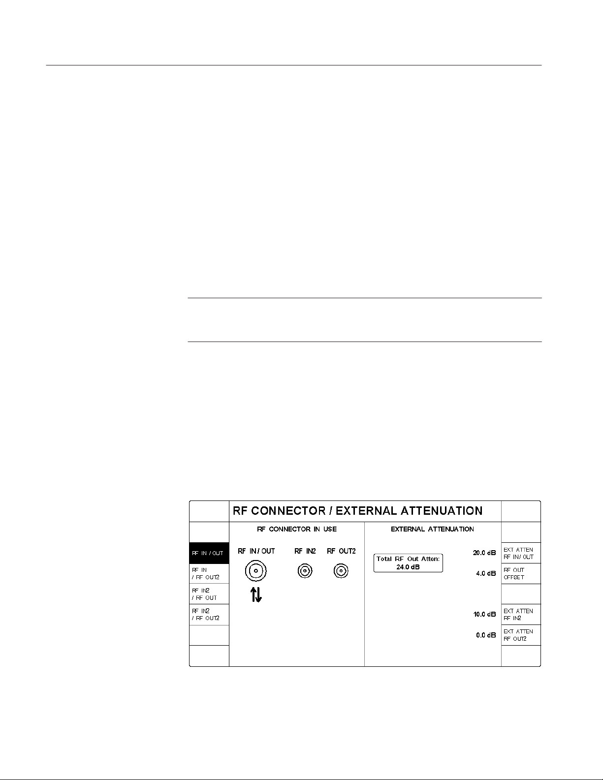
Getting Started
H SIGNAL @ REF OUT 2. Press this softkey to set the signal available at the
REF OUT 2 connector. The selections are as follows:
H SYSTEM CLOCK (19.6608 MHz)
H INACTIVE
H PP2S (pulse per 2 seconds)
H SUPER FRAME (80 ms)
H PAGING FRAME (20 ms)
H SYNC FRAME (26.67 ms)
H PWR CONTROL FRAME (1.25 ms)
NOTE. The REF OUT 2 connector provides a TDMA superframe signal when the
tester is in TDMA mode. The superframe signal is a positive logic signal with an
80 ms period.
RF CONNECT/EXT ATTEN
H SYSTEM CLOCK DIVISOR. This softkey is displayed if the SIGNAL @
REF OUT 2 is set to SYSTEM CLOCK. Press this softkey to select the
divisor used to divide the system clock frequency.
H TIMING SIG DEFAULTS. Press this softkey to set the timing signals to the
default settings.
This softkey displays a menu to select the front-panel RF IN/OUT connectors
and external attenuation for your test setup (see Figure 1–16).
1–16
Figure 1–16: RF connector and external attenuation menu
CMD 80 Digital Radiocommunication Tester User Manual

Getting Started
The softkeys on the left select the front-panel input and output RF connectors
you intend to use.
H RF IN/OUT. Press this softkey to select the bidirectional RF IN/RF OUT
front-panel RF connector for both input and output signals to and from the
tester.
H RF IN / RF OUT2. Press this softkey to select front-panel RF IN/RF OUT
connector as the input signal path to the tester and the front-panel RF OUT 2
connector as the output signal path from the tester.
H RF IN2 / RF OUT. Press this softkey to select the front-panel RF IN 2
connector as the input signal path to the tester and the front-panel RF IN/RF
OUT connector as the output signal path from the tester.
H RF IN2 / RF OUT2. Press this softkey to select the front-panel RF IN 2
connector as the input signal path to the tester and the RF OUT 2 connector
as the output signal path from the tester.
The softkeys on the right side to correct for any external attenuation in the
connection path.
H EXT ATTEN RF IN/OUT. Press this softkey to set the amount of external
gain or attenuation present in the connection to the mobile station when
using the RF IN/OUT connector. A positive value indicates attenuation (loss)
and a negative value indicates gain in the signal path.
The tester uses this value as a correction factor for RF power measurements
and also to correct the RF output power so that the power presented to the
mobile station is equal to the instrument front-panel setting.
H RF OUT OFFSET. Press this softkey to set the additional correction factor
(attenuation or gain) present in the forward RF path (base station to mobile
station). This factor is applied in addition to the EXT ATTEN RF IN/OUT
correction factor.
H EXT ATTEN RF IN2. Press this softkey to set the amount of external gain or
attenuation present in the connection to the mobile station when using the
RF IN2 connector. A positive value indicates attenuation (loss) and a
negative value indicates gain in the signal path.
The tester uses this value as a correction factor for RF power measurements.
H EXT ATTEN RF OUT2. Press this softkey to set the amount of external gain
or attenuation present in the connection to the mobile station when using the
RF OUT2 connector. A positive value indicates attenuation (loss) and a
negative value indicates gain in the signal path.
The tester uses this value to correct the RF output power so that the power
presented to the mobile station is equal to the instrument front-panel setting.
CMD 80 Digital Radiocommunication Tester User Manual
1–17

Getting Started
GPIB/IEC ADDRESS
PRINTER
Press this softkey to set the tester’s GPIB address. Use the numeric key pad to
enter a value between 1 and 30.
Press this softkey to display the PRINTER CONFIGURATION menu (see
Figure 1–17). Use this menu to specify the type of printer connected to the rear
panel printer connector. Table 1–1 provides a list of the currently supported
printer types. Figure 2–5 on page 2–8 shows the location of the printer connector.
Figure 1–17: Printer configuration menu
T able 1–1: Supported printers
Printer type Printer type Printer type
Epson EPL Series HP DeskJet Series (B/W) NEC Colormate PS
Epson EX Series (B/W) HP DeskJet 500c (Color) NEC LC-890 Laser
Epson EX Series (Color) HP DeskJet 550c (Color) NEC Pinwriter P2/P3
Epson FX Series HP DeskJet 1200C (Color) NEC Pinwriter Series (24–B/W)
Epson FX Series (B/W) HP LaserJet Series I NEC Pinwriter Series (24-Clr)
Epson FX Series (Color) HP LaserJet Series II NEC Silent Writer2 990
Epson LQ Series (24-pin, B/W) HP LaserJet Series III NEC Silentwriter LC-860+
Epson LQ Series (24-pin, Color) HP LaserJet Series IV R&S Ink-Jet CM-222
Epson LQ Series (8-pin, B/W) HP PaintJet Series (B/W)
Epson LQ Series (8-pin, Color) HP PaintJet Series (Color)
Epson MX Series HP PaintJet XL300 (8.5I x 11I)
Epson RX Series HP PaintJet XL300 (11I x 17I)
1–18
CMD 80 Digital Radiocommunication Tester User Manual

Getting Started
OTHER
Press this softkey to display the OTHER CONFIGURATIONS menu (see
Figure 1–18). You can use this menu to do the following:
H KEY CLICK. Press this softkey to turn on the key click function, which
produces an audible click each time you press a front-panel key.
H ACOUSTIC WARNINGS. Press this softkey to turn on the acoustic
warnings function, which produces a beep if you attempt to perform an
illegal action.
H DATE. Press this softkey to set the system date (month, day, year). Use
periods to separate the entries.
H TIME. Press this softkey to set the system time (hours, minutes, seconds).
Use periods to separate the entries.
Figure 1–18: Other configurations menu
CMD 80 Digital Radiocommunication Tester User Manual
1–19

Getting Started
OPTIONS
Press this softkey to display a list of the options installed in your tester. Options
that are installed are indicated by a check mark (n) in their fields. See Figure 1–19.
Figure 1–19: Options display
Use the CODE softkey to enable firmware options. Contact your sales representative for details.
Table 1–2 lists the available options for the CMD 80 Digital Radiocommunication Tester.
T able 1–2: List of options
Tektronix option Rohde & Schwarz option Function
396-4905-00 ZZA-94 19 inch rack mount kit
B1 CMD-B1 High-stability reference oscillator
B81 CMD-B81 Additive White Gaussian Noise (AWGN)
generator
B3 CMD-B3 Multireference frequency inputs and outputs
B61 CMD-B60 Adapter for B61 and B62
B61 CMD-B61 IEEE 488 (GPIB) bus interface
B61 CMD-B62 Memory card interface
B14 CMD-B14 13k vocoder rate (14.4k data rate)
B82 CMD-B82 Adds Analog mode operation
(Standard) CMD-K1 Adds cellular operation
K2 CMD-K2 Adds PCS operation
B84 CMD-B84 Adds TDMA mode operation
1–20
CMD 80 Digital Radiocommunication Tester User Manual


Operating Basics
This chapter describes the front and rear panel controls and connectors. It also
provides a brief description of the menu selections and how they are used.
Front-Panel Display, Controls, and Connectors
Figure 2–1 illustrates the front panel. Refer to this illustration when reading the
description for a particular area.
Softkeys SoftkeysDisplay area Data keypad
Memory card and
hardkey area
Figure 2–1: CMD 80 Digital Radiocommunicaton T ester front-panel controls and connectors
CMD 80 Digital Radiocommunication Tester User Manual
2–1

Operating Basics
Softkeys
The softkeys are the eight keys to the left and eight keys to the right of the
display area. Each softkey has mutiple functions depending on the operating
mode. The current function is displayed directly next to the softkey in the
display area. If the display area next to a softkey is blank, the softkey has no
function.
Numerical Entry. With the softkey on a bright background, data cannot be entered.
Pressing a softkey changes the softkey display to a dark background and allows
data to be entered. For some entries, a small VAR symbol appears, indicating
that the VAR control can be used. Entry is as follows:
Rotating the VAR control increases or decreases the setting value.
Pressing the first key in the data area causes an input window to open displaying
the first digit. At this point, the VAR control cannot be used. Enter additional
digits using the keypad. The BACKSPACE key deletes the last digit, the
CLEAR key clears the complete entry, and the STOP BREAK key closes the
input window without recording the value. Press the ENTER key or a unit key to
set the value and close the input window. Once this is done, the VAR control is
reactivated.
Selection With Softkeys. In addition to numeric entry, softkeys are used to select
various displays. For example, the POWER CONTROL GATED OUTPUT
display is available in one of three formats:
Display Area
H Full display (see Figure 3–13 on page 3–19)
H Rising edge (see Figure 3–14 on page 3–20)
H Falling edge (see Figure 3–14 on page 3–20)
The active softkey selection is indicated by a dark background.
Loop T oggle. Two (or more) operating states can be displayed next to a softkey.
The active state is indicated by an inverse video display. You can switch
operating states by pressing the softkey.
The display area shows the menu headings, descriptions of the softkey functions,
settings, measured values, and status messages. The contents of the display
change depending on the menu selected. The display also may be affected by the
options that are installed in your tester.
Measurement conventions. Failed measurements are returned in reverse video
(white text on black background). Measurements with “– – –” indicate that the
tester was not able to make a valid measurement. NAN is displayed if the value
is not a number.
2–2
CMD 80 Digital Radiocommunication Tester User Manual

Operating Basics
Data Keypad
This area is used to enter data for a particular function. The controls in this area
are illustrated in Figure 2–2.
1
6
5
4
2
3
Figure 2–2: Detail of data keypad area
1. Numeric Keypad. Use the numeric keypad to enter digits 0 through 9.
The unit keys to the right of the numeric keys provide the appropriate units
for an entry and are context sensitive.
For example, if you press the top key it is interpreted as MHz, mV, %, or the
hexadecimal digit A, depending on the parameter you are specifying.
CMD 80 Digital Radiocommunication Tester User Manual
2–3

Operating Basics
The key units and corresponding functions are as follows:
Key Marked: Function:
MHz Frequency
mV Voltage
% Distortion, for example
A Hexadecimal digit
kHz Frequency
mV Voltage
W Power
B Hexadecimal digit
Hz Frequency
time Time
dBmV Level
C Hexadecimal digit
dB Relative power setting
dBm Power level
rad/° Phase deviation
D Hexadecimal digit
– Minus sign (negative value)
F Hexadecimal digit
. Decimal point
E Hexadecimal digit
2. ENTER ON. This key performs the following functions:
H Terminates all numeric entries not having or not requiring a unit key
termination
H Activates the functions that were deactivated by OFF (usually measure-
ments or levels)
3. VAR. This spinwheel is used to vary a number of functions, usually relating
to the softkey parameters. The spinwheel is also used to position the
MARKER on a display.
4. MENU UP. This key displays the next higher level menu.
5. MENU HOME. This key displays the highest level menu.
2–4
CMD 80 Digital Radiocommunication Tester User Manual

Operating Basics
6. CLEAR OFF. This key performs the following functions:
H Aborts entries not yet concluded
H Switches off or selects the minimum value when entering values
H Switches off various functions (for example, AWGN or BS frequency
offset)
Memory Card, Hardkey,
and Loudspeaker Area
The slot in the memory card area is used to insert the optional PCMCIA memory
card. Keys in the hardkey area perform dedicated functions. The keys are located
below the MEMORY CARD slot (see Figure 2–3).
14
13
12
11
10
1
2
3
4
5
9
8
Figure 2–3: Detail of memory card, hardkey , and loudspeaker areas
NOTE. Not all hardkeys have functions assigned to them. Keys that do not have
functions assigned are for future enhancements.
CMD 80 Digital Radiocommunication Tester User Manual
6
7
2–5

Operating Basics
1. RECALL. This hardkey accesses the menu to recall saved tester states.
You can recall setups from the internal hard drive or a PCMCIA memory
card (option installation required).
2. USER. This hardkey displays a menu from which you select the user
number. Each user number has its own set of states that can be recalled when
you press the RECALL key. You can store the tester states using the SAVE
key.
3. RESET. This hardkey sets the tester to a default state.
4. KEY HELP. This hardkey is not used.
5. CONFIG. This hardkey displays the configuration menu for particular
functions of the original menu. Not all menus use this function.
6. LOCAL. This hardkey switches from Remote (GPIB or RS-232 control) to
Local (manual control).
7. START CONT. This hardkey is not used.
8. Loudspeaker. The loudspeaker is used when you have the key click function
or audible warnings turned on.
9. STOP BREAK. Press this hardkey to abort editor entries.
10. BACK SPACE. This hardkey deletes the figure last entered from the keypad.
11. ILLUM. This hardkey is not used.
12. HARD COPY. This hardkey sends a copy of the display area to the printer.
13. MEM CARD. This hardkey is not used.
14. SAVE. This hardkey accesses the menu to save tester states.
You can store setups to the internal hard drive or a PCMCIA memory card
(option installation required). It is recommended that you use a PC card with
128 kB or greater memory capacity.
NOTE. You must format the memory card on an MS-DOS personal computer
prior to use with the tester.
2–6
CMD 80 Digital Radiocommunication Tester User Manual

Operating Basics
Front-Panel Controls and
Connectors
The remaining front-panel controls and connectors are located at the bottom of
the front panel as illustrated in Figure 2–4.
1 2 3 4 5 6 8 107 119
Figure 2–4: Front-panel controls and connectors
1. RF IN/RF OUT. This is a bidirectional RF connector. It provides both an
input and output for RF signals from instruments. The antenna connection of
a mobile phone is usually connected here.
2. RF IN 2. This connector is a sensitive RF input which can be used as an
alternative to the RF IN/RF OUT signal.
3. RF OUT 2. This connector provides a high-level RF output signal as an
alternative to the RF IN/RF OUT signal.
4. MULTIFUNCTION. This 50-contact connector is reserved for future
options.
5. AF GEN OUTPUT. This connector provides audio-frequency tones. This
output is active only if the tester has Option B82 (AMPS) installed in it.
6. AF VOLTM INPUT. This connector is used to measure audio-frequency
tones. This connector is active only if the tester has Option B82 (AMPS)
installed in it.
7. VOLUME/CONTRAST. The center knob has no function. The outer knob
adjusts the contrast of the display area.
8. I
. These connectors are used to measure the DC current. The left
DC
connector is positive.
9. V
. These connectors are used to measure the DC voltage. The left
DC
connector is positive.
10. PROBE. This connector is reserved for future options.
11. STANDBY/ON. This is the front-panel power switch. When engaged, all test
modules are powered. When disengaged, only the Standby LED is powered.
CMD 80 Digital Radiocommunication Tester User Manual
2–7

Operating Basics
Rear-Panel Controls and Connectors
The rear-panel controls and connectors are shown in Figure 2–5. Refer to the
figure when reading the description for each area.
1
2345
6789
Figure 2–5: Rear-panel controls and connectors
1. Power Connector Area. This area has the following items:
H Power connector. Use this to connect external power to the tester.
H Fuse holder. This holder contains the power line fuse.
H Power switch. This is the master power switch that isolates all poles of
the power supply.
2. SERVICE. This connector is for use by factory personnel only.
CAUTION. To prevent equipment damage, do not make any connection to the
SERVICE connector on the rear panel.
2–8
CMD 80 Digital Radiocommunication Tester User Manual

Operating Basics
3. RF OUT 10 MHz/REF IN. This is an optional output connector for the
reference frequency of the measuring instrument: 10 MHz or signal of REF
IN connector (without resynchronization). Refer to the Reference Timing
section on page 1–15 for details.
4. REF OUT 2. This is an optional output connector for CDMA timing signals.
Refer to Reference Timing on page 1–16 for details.
5. REF IN. This is an optional reference frequency input connector.
6. RS-232. This connector is a remote control interface and is also used to
update the tester operating system.
7. PRINTER. This is a 25-contact Centronics connector, which is used to
connect a printer.
8. KEYBOARD. This connector is not used.
9. IEEE BUS. This connector is an optional IEEE 488/IEC 625 (GPIB)
interface.
Menu Structures
Other rear panel connectors are provided for future expansion.
CAUTION. To prevent equipment damage, open ports should not be used even
when a connector is present.
You control the tester with the menu selections displayed on the screen. The
menus allow you to configure the tester and and perform the measurements.
Some menus simply toggle or select a setting while others display subsequent
menu screens.
The menu structure divides logically into two main sections: test menus and
configuration menus. For the standard tester, these menus are used to set up and
perform tests on CDMA (digital) mobile stations. If you have Option B82 or
Option B84 installed, your tester also has menus that allow you to set up and
perform tests on Analog or TDMA mode mobile stations.
CMD 80 Digital Radiocommunication Tester User Manual
2–9

Operating Basics
The following illustration shows the partial menu structure of the CDMA
CONFIGURATION MENU.
CONFIG MENU
MANUAL TEST
STANDBY POWER
POWER CONTROL
OPEN LOOP TIME RESPNS
MINIMUM OUTPUT
MAXIMUM OUTPUT
GATED OUTPUT
To access the Power Control configuration menu for the Gated Output function,
perform the following steps:
1. Press the MENU HOME front-panel key to display the home menu.
Returning to the home menu returns the tester to an idle state thus dropping
an established call to a mobile station.
2. Press the SYSTEM softkey to select CDMA. This softkey is available if
other system selections other than CDMA are installed.
3. Press the CONFIG MENU softkey to display the CONFIGURATION
MENU.
4. Press the MANUAL TEST softkey to display the CDMA MANUAL TEST
CONFIGURATION menu.
5. Press the POWER CONTROL softkey to display the POWER CONTROL
CONFIGURATION menu.
6. Press the softkey for the function whose parameters you want to set.
Figure 3–3 on page 3–6 shows the CDMA menu tree; Figure 3–29 on page 3–48
shows the CDMA configuration menu tree.
Figure 3–32 on page 3–53 shows the analog test menu tree; Figure 3–89 on
page 3–118 shows the Analog configuration menu tree.
Figure 3–133 on page 3–169 shows the TDMA test menu tree; Figure 3–181 on
page 3–229 shows the TDMA configuration menu tree.
NOTE. For the analog or TDMA test and configuration menus to appear on the
display, your tester must have Option B82 or Option B84) installed in it.
2–10
CMD 80 Digital Radiocommunication Tester User Manual


Reference
This chapter contains more detailed information about using the CMD 80 Digital
Radiocommunication Tester. To simplify usage, this chapter is divided into six
sections.
H Network, System, and Standard contains information about the interactions
between the network, system, and standard settings.
H CDMA Measurements contains information about using the tester to emulate
a Code Division Multiple Access (CDMA) base station and the tests that you
can perform on CDMA mobile stations. This information is applicable to all
testers.
H Analog Measurements (Option B82) contains information about using the
tester to emulate an analog base station and the tests that you can perform on
analog mobile stations. Option B82 must be installed to access the analog
menus and measurements.
H TDMA Measurements (Option B84) contains information about using the
tester to emulate a Time Division Multiple Access (TDMA) base station and
the tests that you can perform on analog mobile stations. Option B84 and
Option B82 must be installed to access the TDMA menus and measurements.
H Additional Measurements contains information about using the tester to
make common voltage and current measurement. This information is
applicable to all testers.
H Audio Measurements contains information about using the tester to make
common audio measurements. This information is applicable to all testers.
CMD 80 Digital Radiocommunication Tester User Manual
3–1

Reference
3–2
CMD 80 Digital Radiocommunication Tester User Manual

Network, System, and Standard


Network, System, and Standard
The NETWORK, SYSTEM, and STANDARD softkey functions interact with
each other (see Figure 3–1) Depending on which network you select, you also
may be required to select a system and a standard. Because of this interaction,
the three softkeys are discussed within this topic.
Network
Figure 3–1: Home menu display
Typically, you first select the network. Then if the SYSTEM softkey is displayed, you select the system. Finally, if after selecting the system, the STANDARD softkey is displayed, you select the standard to which you want to test.
Each of the softkey functions is described in the following subtopics.
Press the NETWORK softkey to activate the VAR control so that you can select
the network for the mobile station you are testing. Note that when you select
NETWORK, a box labeled “VAR” is displayed next to the highlighted NETWORK softkey. This indicates that the VAR control is active. Rotate the control
to select from the following networks:
H US CELLULAR
H JAPAN CELLULAR
H CHINA CELLULAR
H US PCS
H KOREA PCS
H KOREA 2 PCS
Available only with
Option K2
CMD 80 Digital Radiocommunication Tester User Manual
3–3

Network, System, and Standard
System
Standard
Press the SYSTEM softkey to select the system that you want to test. The system
selections interact with the selection made for the Network.
If you select US CELLULAR, JAPAN CELLULAR, or CHINA CELLULAR as
the network and the tester has more than one system capability installed, you
must select the system for which you want to test your mobile station. Press the
SYSTEM softkey to toggle between the selections available (CDMA, ANALOG,
or TDMA). All other network choices test the CDMA system only. (CDMA is
displayed in a rounded box.)
Press this softkey to select the standard that you want to test. This softkey
interacts with both the NETWORK and SYSTEM settings.
The tester displays the STANDARD softkey whenever there is more than one
available standard for the selected network. Press the STANDARD softkey to
toggle between the choices. Table 3–1 shows the standards for each network and
system.
NOTE. If there is only one standard available for the selected network and
system, the tester displays the default standard in the lower right corner in a
rounded box.
T able 3–1: Available standard choices
NETWORK SYSTEM STANDARD
US CELLULAR CDMA
US PCS CDMA
JAP AN CELLULAR CDMA
CHINA CELLULAR CDMA
KOREA PCS CDMA UB IS-95 or J-STD008
KOREA 2 PCS CDMA UB IS-95 or J-STD008
1
Available with Option B84.
2
Available with Option B82.
1
TDMA
ANALOG
1
TDMA
ANALOG
ANALOG
2
2
2
IS-95
IS-136-A
AMPS or NAMPS
UB IS-95 or J-STD008
IS-136-A
IS-95 or T53
NT ACS or JTACS
IS-95
ET ACS or TACS
3–4
CMD 80 Digital Radiocommunication Tester User Manual

CDMA Measurements


CDMA
Using the Home Menu
This section describes the operation and configuration of the CDMA tests that
the CMD 80 Digital Radiocommunication Tester can perform. Some menu items
and softkeys are associated with a specific option. If you do not have that option
installed, the supporting menus and softkeys do not appear in the display.
This section discusses the tests and station configurations that are exclusive to
the CDMA system.
After power on, the tester displays the home menu (see Figure 3–2). You can
press the MENU HOME front-panel key to return to this menu at any time. The
softkeys displayed by this menu allow you to select from a number of main
topics.
From this menu you can select the Network, System, (and Standard if appropriate). Once these are set, you can use the other softkeys to proceed to the
measurement tests or to the configuration menus.
Figure 3–2: Home menu display
The softkey menus discussed in this section are the MANUAL TEST, MODULE
TEST, and CONFIG MENU as they are defined by setting the system to CDMA
mode.
CMD 80 Digital Radiocommunication Tester User Manual
3–5

CDMA
For detailed descriptions about the ADDITIONAL MEASUREMENT softkey,
refer to page 3–255. For detailed descriptions about the AUDIO MEASUREMENT softkey, refer to page 3–257. For detailed descriptions about the
NETWORK, SYSTEM, and STANDARD softkeys, refer to page 3–3.
To see displays on your tester similar to the ones shown in this section, you need
to set the network to US CELLULAR and the system to CDMA. Use the
following steps:
1. Press the NETWORK softkey to activate the VAR control so that you can
select the network for the mobile station you are testing. Rotate the VAR
control to select US CELLULAR as the network.
2. Press the SYSTEM softkey to select CDMA as the system. This softkey is
only available if you have Analog mode (Option B82) and/or TDMA mode
(Option B84) installed). If neither of these options are installed, CDMA
appears in a rounded box.
Some of the softkey selections in the home menu have several levels of
submenus associated with them. Figure 3–3 shows the CDMA menu structure
for the tester. This subsection contains a description of each of these menus and
their softkeys.
MENU HOME
ADDITIONAL MEASUREMENT
MANUAL TEST
MODULE TEST
AUDIO MEASUREMENT
NETWORK
SYSTEM
CONFIG MENU
STANDARD
MS UNREGISTERED
MS REGISTERED
ADDITIONAL MEASUREMENT
POWER CONTROL
RECEIVER QUALITY
TRANSMITTER QUALITY
HANDOFFS/TRANSITIONS
BS SIGNAL CONFIG
ADDITIONAL MEASUREMENT
BS SIGNAL CONFIG
CALL TO MOBILE - VOICE LOOP BACK
CALL TO MOBILE - MS TESTS
OPEN LOOP TIME RESPNS
MINIMUM OUTPUT
MAXIMUM OUTPUT
GATED OUTPUT
CONTINUOUS
SINGLE SHOT
PHASE ERROR
MAGNITUDE ERROR
ERR VECTOR MAGNITUDE
ADDITIONAL MEASUREMENT
HANDOFFS/TRANSITIONS
BS SIGNAL CONFIG
GO TO SINGLE SHOT
SENSITIVITY
DYNAMIC RANGE
DEMOD OF TRAFFIC CH
CURRENT SIGNAL LVL
USER DEFINED 1
USER DEFINED 2
GO TO CONTINUOUS
SENSITIVITY
DYNAMIC RANGE
DEMOD OF TRAFFIC CH
CURRENT SIGNAL LVL
USER DEFINED 1
USER DEFINED 2
Figure 3–3: CDMA manual test menu tree
3–6
CMD 80 Digital Radiocommunication Tester User Manual

Manual Test (Signaling)
CDMA: Manual Test (Signaling)
The MANUAL TEST softkey (from the home menu) selects the manual test
measurements for the system selected with the SYSTEM softkey. This section
discusses the tests available when you have selected CDMA as the system.
Press the MANUAL TEST softkey to display the menu used to perform call
processing and measurements on CDMA mobile stations (see Figure 3–4).
Selecting this test initiates a sequence composed of three states:
1. MS Unregistered (initialization)
2. MS Registered (idle/access)
3. Call Established
MS Unregistered
The first stage of the manual test is the MS Unregistered (initialization) state,
which is started by pressing the MANUAL TEST softkey. During this initialization state, the tester establishes contact with the mobile station and enables the
output power from the tester. Figure 3–4 shows the display during this state.
Figure 3–4: MS unregistered menu (initialization state)
You can use either of the two CALL TO MOBILE softkeys to initiate a call to
the mobile station, or you can place a voice loopback call from the mobile
station by entering any telephone number on the mobile station and pressing
SEND.
CMD 80 Digital Radiocommunication Tester User Manual
3–7

CDMA: Manual Test (Signaling)
The following softkeys are available in the MS Unregistered state:
H ADDITIONAL MEASUREMENT. Refer to Additional Measurements on
page 3–255.
H ACCESS PROBES. Press this softkey to toggle the ACCESS PROBES state
between ACKNOWLEDGE and IGNORE.
IGNORE prevents the registration process from proceeding, and allows the
user to more easily observe the Access Probe Power measurement.
H TIMER BASED REGISTRATN. Press this softkey to set the interval that
the mobile station will use to register with the tester. You can use the VAR
control to set a range of values from 12 seconds to approximately 2 minutes.
If you select OFF, the mobile station discontinues periodic registration with
the tester.
H MOBILE ID. Press this softkey to enter the MIN or IMSI (mobile ID) of the
mobile station. You are not required to provide this information. However,
entering the mobile ID provides the tester with the necessary information so
that you can use the CALL TO MOBILE softkeys without waiting for
registration. This number is retained from the last entered value or the last
mobile station to register with the tester.
NOTE. The tester requires either a MIN or an IMSI mobile identification type.
(You select the ID type in the CDMA BS PARAMETERS CONFIGURATION
menu (refer to CDMA BS PARAMETERS on page 3–49.) For some protocol
revisions, you can choose either a MIN or an IMSI mobile ID. For other protocol
revisions, a choice of mobile ID is not available. In the latter case, the CDMA
BS PARAMETERS CONFIGURATION menu does not display the MOBILE ID
TYPE softkey; instead, it displays the mobile ID type in a rounded box below the
protocol revision field.
H CDMA BS SIGNAL CONFIG. This softkey displays the configuration
menu where you can define the components of the base station signal. These
include the levels of the pilot, sync, and paging channels and other parameters, such as traffic channel and frame offset that are used when a call is set
up.
H PREFERRED VOCODER. This softkey is displayed only if you have
selected RATE SET 1 (8K) as the preferred rate set. Press this softkey to
select the preferred vocoder, either BASIC or ENHANCED. If the rate
selected is not supported by the mobile station, the tester reverts to the
supported rate.
H PREFERRED RATE SET. This softkey enables you to select either the 8K
or 13K vocoder rates (option B14 installation is required). If the rate selected
is not supported by the mobile station, the tester reverts to the supported rate.
3–8
CMD 80 Digital Radiocommunication Tester User Manual

CDMA: Manual Test (Signaling)
H CALL TO MOBILE. Activation of the upper softkey causes the tester to
initiate a voice loopback call to the mobile station. Pressing the lower
softkey initiates the mobile station loopback tests (Service Option 2 as
specified in IS-126).
CDMA MANUAL TEST MS Unregistered Configuration Menu. While in the MS
Unregistered (initialization) state, you can press the front-panel CONFIG key to
access the configuration menu (see figure 3–5).
Figure 3–5: CDMA manual test configuration menu (unregistered state)
This configuration menu gives you access to the configuration menus for the
following modes:
H STANDBY POWER. This softkey displays the standby power configuration
menu, where you can set the maximum limit of standby power and toggle
the auto stop function on or off, or set the parameters to their default values.
H ACCESS PROBES. This softkey displays the access probes configuration
menu, where you can define the nominal offset, initial offset, probe
increment, number of probes per sequence, and the number of sequences per
attempt. See figure 3–6.
H MULTIPLE PILOTS. This softkey displays the multiple pilots configuration
menus, where you can define the PN offsets, pilot levels, T_ADD, and
T_DROP for multiple pilot tests. See figures 3–23 and 3–24, on page 3–39.
H SOFTER HANDOFF. This softkey displays the softer handoff configuration
menu, where you can define the parameters for softer handoff. These
include: fer interval, maximum FER %, T_ADD and T_DROP levels, total
power, and the secondary sector PN offset and traffic channel. See figure
3–25 on page 3–40.
CMD 80 Digital Radiocommunication Tester User Manual
3–9

CDMA: Manual Test (Signaling)
H BS SIGNAL CONFIG. This softkey displays the configuration menu where
you can define the components of the base station signal. These include the
levels of the pilot, sync, and paging channels and other parameters, such as
traffic channel and frame offset that are used when a call is set up.
ACCESS PROBES configuration menu. Enter the Access Probes configuration
menu, see figure 3–6, by pressing the ACCESS PROBES softkey while in any of
the CDMA Manual Test configuration menus.
Figure 3–6: Access probes configuration menu
H NOMINAL OFFSET. Press this softkey to use the VAR control to set the
nominal transmit power offset (“NOM_PWR” of the Access Parameters
Message). Used in the computation of the mean output power of the access
probes.
Range: –8 dB to 7 dB.
H INITIAL OFFSET. Press this softkey to set the initial power offset for access
(“INIT_PWR” of the Access Parameters Message) with the VAR control.
Used in the computation of the mean output power of the access probes.
Range: –16 dB to 15 dB.
H PROBE INCREMENT. Press this softkey to use the VAR control to set t
!
Range: 0 to 7 dB
H PROBES PER SEQUENCE. Press this softkey to set the number of access
probes per sequence (“NUM_STEP” of the Access Parameters Message + 1)
3–10
CMD 80 Digital Radiocommunication Tester User Manual

CDMA: Manual Test (Signaling)
with the VAR control. Establishes the maximum number of access probes
transmitted in a single sequence.
Range: 1 to 16
H SEQUENCES PER ATTEMPT. Press this softkey to use the VAR control to
set the number of access probe sequences per access attempt
(“MAX_REQ_SEQ” or “MAX_RSP_SEQ” of the Access Parameters
Message). Establishes the maximum number of access probe sequences
transmitted for either an access channel request or access channel response.
Range: 1 to 15
H DEFAULTS. Press this softkey to return all access probe parameters to their
factory default values.
MS Registered
After the mobile station is powered on and registered, the tester enters the MS
Registered (idle/access) state. Figure 3–7 shows the display during this state.
Figure 3–7: MS registered menu (idle/access state)
The tester displays the mobile station information on the left side of the screen
and the base station information on the right side. You can use either of the two
CALL TO MOBILE softkeys to initiate a call to the mobile station, or you can
place a voice loopback call from the mobile station by entering any telephone
number on the mobile station and pressing SEND.
CMD 80 Digital Radiocommunication Tester User Manual
3–11

CDMA: Manual Test (Signaling)
NOTE. If the mobile station is not compliant with J-STD-008 and the power class
information is not reported, the Power Class field displays “–––” instead of a
value; also, the tester will assume that the mobile station is a Power Class 5
mobile station and limit its output power to +8 dBm (except in the Maximum
Output Power test).
The following softkeys are available in the MS Registered menu:
H ADDITIONAL MEASUREMENT. Refer to Additional Measurements on
page 3–255.
H TIMER BASED REGISTRATN. Refer to TIMER BASED REGISTRATN on
page 3–8.
H BS SIGNAL CONFIG. Refer to CDMA BS SIGNAL CONFIG on page 3–8.
H PREFERRED VOCODER. This softkey is displayed only if you have
selected RATE SET 1 (8K) as the preferred rate set. Press this softkey to
select the preferred vocoder, either BASIC or ENHANCED. If the rate
selected is not supported by the mobile station, the tester reverts to the
supported rate.
H PREFERRED RATE SET. This softkey enables you to select either the 8K
or 13K vocoder rates (option B14 installation is required). If the rate selected
is not supported by the mobile station, the tester reverts to the supported rate.
H CALL TO MOBILE. Activation of the upper softkey causes the tester to
initiate a voice loopback call to the mobile station. Pressing the lower
softkey initiates the mobile station loopback tests (Service Option 2 as
specified in IS-126).
CDMA MANUAL TEST MS Registered configuration menu. While in the MS
Registered state, you can press the front-panel CONFIG key to access the
configuration menu (see figure 3–8).
3–12
CMD 80 Digital Radiocommunication Tester User Manual

CDMA: Manual Test (Signaling)
Figure 3–8: CDMA manual test configuration menu (registered state)
Use this configuration menu to access the configuration menus for the following
modes:
H STANDBY POWER. This softkey displays the standby power configuration
menu, where you can set the maximum limit of standby power and toggle
the auto stop function on or off, or set the parameters to their default values.
H ACCESS PROBES. This softkey displays the access probes configuration
menu where you can define the nominal offset, initial offset, probe increment, number of probes per sequence, and the number of sequences per
attempt. See figure 3–6.
H MULTIPLE PILOTS. This softkey displays the multiple pilots configuration
menu, where you can define the PN offsets, pilot levels, T_ADD, and
T_DROP for multiple pilot tests. See figures 3–23 and 3–24.
H SOFTER HANDOFF. This softkey displays the softer handoff configuration
menu where you can define the parameters for softer handoff. These include:
FER interval, maximum FER %, T_ADD and T_DROP levels, total power,
and the secondary sector PN offset and traffic channel. See figure 3–25.
H BS SIGNAL CONFIG. This softkey displays the configuration menu where
you can define the components of the base station signal. These include the
levels of the pilot, sync, and paging channels and other parameters, such as
traffic channel and frame offset that are used when a call is set up.
Call to Mobile (Voice
Loopback)
CMD 80 Digital Radiocommunication Tester User Manual
When you press the CALL TO MOBILE softkey for voice loopback and
establish a call, the tester displays the menu shown in Figure 3–9. In this mode, a
message spoken into the mobile station is returned in approximately two
seconds. This allows you to test the quality of the call.
3–13

CDMA: Manual Test (Signaling)
Figure 3–9: Call established menu for voice loopback
Once the voice loopback call is established, the following softkeys are available:
H ADDITIONAL MEASUREMENT (refer to page 3–255)
H HANDOFFS/TRANSITIONS (refer to page 3–33)
H BS SIGNAL CONFIG (refer to page 3–35)
H TOTAL POWER (refer to page 3–36)
H RF CHANNEL (refer to page 3–36)
H TRAFFIC CHANNEL (refer to page 3–36)
H FRAME OFFSET (refer to page 3–37)
H PN OFFSET (refer to page 3–37)
H RELEASE CALL. Press this softkey to simulate termination of the call by
the base station. You can also release the call at the mobile station by
hanging up the mobile station (press END on the mobile station).
3–14
CMD 80 Digital Radiocommunication Tester User Manual

CDMA: Manual Test (Signaling)
Call to Mobile (MS Tests)
When you press the CALL TO MOBILE softkey for MS TESTS (Service Option
2 as specified in IS-126), the tester displays the menu shown in Figure 3–10.
Figure 3–10: Call established menu for ms tests
This menu displays measurements for the mobile station on the left side of the
display and displays base-station parameters on the right. The displayed results
are updated about once a second. The tester displays any value that exceeds the
limits established during configuration as inverse video (white on black). Refer
to Configuration starting on page 3–48 for setting limits.
At this menu level, data transfers to the mobile unit at the full rate. The network
status box in the upper right corner of the display shows the rate set that is in use
for the call.
The value in the TOTAL POWER EXPECTED field is an internal tester
calculation based on the presumed application of the open loop power control
algorithm. The maximum value is limited by the reported power class of the
mobile station. This method of determining expected power is used for all tests
except the Maximum/Minimum Output Power test.
NOTE. For accurate expected power readings, ensure that you have properly set
the external gain or attenuations settings (refer to RF CONNECT/EXT ATTEN
on page 1–16).
Once the MS TESTS call is established, the following softkeys are available:
H ADDITIONAL MEASUREMENT (refer to page 3–255)
H POWER CONTROL (refer to page 3–16)
CMD 80 Digital Radiocommunication Tester User Manual
3–15

CDMA: Manual Test (Signaling)
H RECEIVER QUALITY (refer to page 3–21)
H TRANSMITTER QUALITY (refer to page 3–26)
H MULTIPLE PILOTS (refer to page 3–28)
H SOFTER HANDOFF (refer to page 3–30)
H HANDOFFS/TRANSITIONS (refer to page 3–33)
H BS SIGNAL CONFIG (refer to page 3–35)
H TOTAL POWER (refer to page 3–36)
H RF CHANNEL (refer to page 3–36)
H TRAFFIC CHANNEL (refer to page 3–36)
H FRAME OFFSET (refer to page 3–37)
H PN OFFSET (refer to page 3–37)
Additional Measurement
Power Control
H RELEASE CALL. Press this softkey to simulate termination of the call by
the base station. You can also release the call at the mobile station by
hanging up the mobile station (press END on the mobile station).
Refer to Additional Measurements on page 3–255.
Press this softkey to configure and perform tests of the power control system.
The tests available are: Open Loop Time Response, Minimum Output, Maximum Output, and Gated Output. Selection of a test item activates the test and
begins the display of results.
If the test displays a waveform, an area at the bottom of the display shows the
time in segments. If the test results are outside the template limit for a particular
time segment, that segment is darkened.
3–16
CMD 80 Digital Radiocommunication Tester User Manual

CDMA: Manual Test (Signaling)
Open Loop Time Response. Press this softkey to test the open-loop power control
of the mobile station in response to an increase or decrease in base station total
power. The default increase or decrease for this test is 20 dB. Figure 3–11 shows
the response to this test.
Figure 3–11: Open loop time response display
The tester performs an initial test when it opens this menu; you can perform
additional measurements by pressing the STEP UP and STEP DOWN softkeys.
You can change the step size and direction by pressing the CONFIG front-panel
key. The minimum increase or decrease is 1 dB.
NOTE. The measurement display indicates all step changes with a positive slope.
During the open-loop test, the closed-loop power is controlled to prevent
unwanted interaction; this is achieved by alternately sending up and down power
control bits to the mobile station.
Defective mobiles can produce power spikes at certain power steps during the
OLTR test, which can result in a digitizer overflow in the tester. Digitizer
overflow is reported as “OVL” instead of “– – –” in the INITIAL MS POWER
display. Displaying “– – –” indicates that no measurement has been made.
When this overflow condition occurs neither the front panel display nor the
GPIB results data buffer are updated. They retain and display (or return) the
values of the most recent successful measurement. If the INITIAL MS POWER
display shows “OVL”, ignore the displayed results.
CMD 80 Digital Radiocommunication Tester User Manual
3–17

CDMA: Manual Test (Signaling)
Minimum Output/Maximum Output. Selecting either of these softkeys starts the
tests using the values selected for total power, traffic level, and pilot level. You
can set the initial values for the base station power by pressing the CONFIG
front-panel key. The results (MS Signal values) are on the left of the display as
shown in Figure 3–12.
NOTE. The connection to the mobile station can be lost when running the
maximum output test if the total power is set too low.
3–18
Figure 3–12: Minimum output and maximum output menus
You can change the specific power levels for total power, traffic level, and pilot
level by selecting their softkeys. Use the VAR control or the DATA keypad to
change the power level values. You can also use the TOTAL PWR AVG COUNT
CMD 80 Digital Radiocommunication Tester User Manual

CDMA: Manual Test (Signaling)
softkey to set how many readings are averaged to determine the total power of
the mobile station. The number of counts can be from 1 to 100.
Results are displayed as a running average, even before the Total Power Average
Count is reached, to eliminate the perceived long measurement time that results
when the Total Power Average Count is set to a high number.
Gated Output. Selecting this test allows you to display the gated output of the RF
carrier in several formats.
NOTE. This test reduces the data transmission rate to one-eighth rate.
Select FULL DISPLAY to display the total period of the IS-98 specified gated
output template. The period of the full display is approximately 1500 ms.
Select RISING EDGE or FALLING EDGE to zoom in to display the 17 ms
period of the rising or falling edge of the waveform. During each of these
displays, a MARKER is activated to display both power amplitude and relative
time. See Figure 3–13.
Figure 3–13: Gated output (full display)
CMD 80 Digital Radiocommunication Tester User Manual
3–19

CDMA: Manual Test (Signaling)
For a more detailed view of the segment illustrated in Figure 3–13, press the
RISING EDGE or FALLING EDGE softkey. The details of the rising and falling
edges are displayed as shown in Figure 3–14.
3–20
Figure 3–14: Gated output (rising edge and falling edge)
CMD 80 Digital Radiocommunication Tester User Manual

CDMA: Manual Test (Signaling)
Receiver Quality
Use this softkey to set up tests of the performance of the mobile receiver. Two
modes of operation are available: continuous mode or single shot mode. You can
toggle between the modes by pressing the upper left softkey. When you select
the continuous mode, you can press the softkey for the BS Signal or Environment parameters you want to change and vary the value by using the VAR
control (see Figure 3–15).
In continuous mode, the tester continuously performs the receiver quality test
and displays the frame error rate over the interval of the most recent number of
frames. You can set this frame error rate interval (CONTINUOUS INTERVAL)
in the configuration menu (refer to Receiver Quality Configuration Menu on
page 3–23).
Figure 3–15: Receiver quality sensitivity (continuous)
If the FER exceeds the maximum FER limit, the FER is displayed in inverse
video (white on black). The frame errors are also displayed in reverse video if
they exceed the number determined by the selected maximum FER and
continuous interval. AUTO STOP is not applied in CONTINUOUS mode.
CMD 80 Digital Radiocommunication Tester User Manual
3–21

CDMA: Manual Test (Signaling)
When you select the single shot mode (see Figure 3–16), the tester will stop the
receiver quality test under the following conditions:
H If you have the auto stop function turned off, the test stops when the number
of frames that you set (single shot duration) is reached.
H If you have the auto stop function turned on, the test stops when one of the
following conditions occurs:
H The confidence level that you set is reached.
H The frame errors reach the maximum limit, based on the single-shot
duration and maximum FER that you set. Simply exceeding the
maximum FER limit will not stop the test, since a falsely high FER can
be generated in the initial portion of a test.
H The number of frames that you set (single shot duration) is reached.
3–22
Figure 3–16: Receiver quality sensitivity (single shot)
CMD 80 Digital Radiocommunication Tester User Manual

CDMA: Manual Test (Signaling)
Receiver Quality Configuration Menu. While in a receiver quality test menu, you
can press the CONFIG front-panel key to display the configuration menu for that
particular test (see Figure 3–17).
Figure 3–17: Sensitivity configuration menu
You can use the configuration menu to set the following parameters for the
receiver quality tests:
H Single shot duration. Press the SINGLE SHOT DURATION softkey to set
the number of frames that are tested. This parameter is used when you
perform a receiver quality test in the single shot mode. The test stops when
the number of frames that you set is reached.
H Confidence level. Press the CONFIDENCE LEVEL softkey to set the level
of confidence to which you want to test. The tester uses this parameter when
you have selected the single shot mode of operation, and you have turned on
the auto stop function. If the frame errors do not exceed the maximum, the
tester will execute the test until the probability of an acceptable frame error
rate reaches the confidence level that you set. At this time, the tester will
stop the test. (If the confidence level is not reached, the test stops when the
single shot duration is reached.)
Use of the confidence level allows a manufacturer to improve the throughput
of a test station by running the receiver quality test only long enough to
obtain the desired confidence level.
H Continuous Interval. Press the CONTINUOUS INTERVAL softkey to set the
number of frames that you want the tester to use to compute the frame error
rate for the continuous mode.
CMD 80 Digital Radiocommunication Tester User Manual
3–23

CDMA: Manual Test (Signaling)
H Data rate. Press the DATA RATE softkey to set the traffic channel data rate.
The selections for the data rate are: FULL, HALF, QUARTER, or EIGHTH.
H Auto stop. Press the AUTO STOP softkey to toggle the auto stop function on
or off. When auto stop is on, the tester performs a single shot receiver quality
test until the number of frames that you set (single shot duration) is reached
or until one of two conditions occurs:
H The confidence level that you set is reached.
H The frame errors reach the maximum limit, based on the single-shot
duration and maximum FER that you set. Simply exceeding the
maximum FER limit will not stop the test, since a falsely high FER can
be generated in the initial portion of a test.
H Maximum frame error rate. Press the MAXIMUM FER softkey to set the
maximum frame error rate. The frame error rate is the percentage of bad
frames with respect to the total number of frames tested. The maximum
frame error rate is the frame error rate limit used to control the inverse video
display of the FER and the FRAME ERRORS fields. For example, in
Figure 3–17 the maximum frame error rate is set to 0.5%. The single shot
duration is 1000 frames. Therefore, the maximum number of frame errors
is 5.
H Total power. Press the TOTAL POWER softkey to set the transmitted power.
H Traffic level. Press the TRAFFIC LEVEL softkey to adjust the level of the
forward traffic channel in the forward CDMA channel.
The TRAFFIC LEVEL softkey specifies the FULL rate traffic channel level.
If a data rate other than FULL is used, the actual test traffic level must be
determined using the following table:
Rate Correction
FULL 0 dB
HALF –3 dB
QUARTER –6 dB
EIGHTH –9 dB
Real level = displayed + correction.
H Pilot level. Press the PILOT LEVEL softkey to adjust the level of the pilot
channel in the forward CDMA channel.
3–24
CMD 80 Digital Radiocommunication Tester User Manual

CDMA: Manual Test (Signaling)
H AWGN LEVEL (Additive White Gaussian Noise Level). This option
provides additional noise to more closely simulate actual operating
conditions. The tester displays the AWGN LEVEL softkey when the optional
AWGN system is installed. Press the AWGN LEVEL softkey to adjust the
level of the AWGN generator. Press the ON or OFF front-panel keys to turn
the AWGN generator on or off.
The tester’s additive white gaussian noise (AWGN) signal is a calibrated,
wideband (1.8 MHz) signal simulating white noise. The AWGN power is
measured across the entire 1.8 MHz bandwidth. In some tests, such as those
specified in IS-98, the described noise power is measured across the
1.23 MHz bandwidth of the CDMA signal. To use the tester’s AWGN signal
for these types of tests, you must set the AWGN level 1.1 dB higher than
specified in IS-98 to compensate for differences in bandwidth.
For example, in IS-98, section 9.3.3, Demodulation of Forward Traffic
Channel in Additive White Gaussian Noise, the specification indicates that
the total AWGN power should be 1.0 dB greater than the total forward traffic
channel power. This specification assumes that the AWGN power is
measured in a 1.23 MHz bandwidth. Since the tester uses a 1.8 MHz
bandwidth to measure its AWGN power, you must compensate for the
difference in noise measurement bandwidth by setting the AWGN level in
the tester 1.1 dB higher than the value specified in the IS-98 test specification.
In this example, where the IS-98 specification calls for a 1.0 dB greater
AWGN level than the forward traffic channel level, you must set the tester’s
AWGN setting to 2.1 dB (the 1.0 dB from the IS-98 specification plus
1.1 dB for bandwidth compensation).
NOTE. The total output power of the tester is the sum of the Forward CDMA
signal plus the AWGN signal. When the Forward CDMA signal is within 10 dB
of its maximum power output, the AWGN signal is turned off. Once the Forward
CDMA signal is no longer within 10 dB of its maximum power, the AWGN signal
level may be set to a new value.
H Base station carrier frequency offset. Press the BS CARRIER FREQ
OFFSET softkey to enter the frequency offset by which you want to shift the
base station carrier. This allows you to test if the mobile station tracks the
base station frequency.
H Defaults. Press the DEFAULTS softkey to set all the parameters to their
preset conditions (typically, the default values are based on IS-98 specifications).
CMD 80 Digital Radiocommunication Tester User Manual
3–25

CDMA: Manual Test (Signaling)
NOTE. The ENVIRONMENT region is present only if the Additive White
Gaussian Noise option is installed. This option provides additional noise to more
closely simulate actual operating conditions.
Transmitter Quality
Use this softkey to test the mobile station transmitter quality. Three sets of tests
are performed by default:
H Carrier feedthrough and I/Q imbalance
H Carrier frequency error and transmit time error
H Waveform quality
One additional test can be selected by pressing one of the following softkeys:
H Phase Error
H Magnitude Error
H Error Vector Magnitude
When you press the softkey associated with a particular test, the graphical output
and the first two lines of the numeric results output change to reflect the results
of that test. Figure 3–18 shows a typical display for the PHASE ERROR test.
This measurement is performed at the FULL data rate.
3–26
Figure 3–18: Transmitter quality menu
The tester displays “–––” when it is not able to make a valid measurement of the
input signal.
CMD 80 Digital Radiocommunication Tester User Manual

CDMA: Manual Test (Signaling)
You can use this menu to set the following parameters:
H Total Power. Press the TOTAL POWER softkey to enable the VAR control
to set the total power output level.
H Traffic level. Press the TRAFFIC LEVEL softkey to adjust the level of the
forward traffic channel in the forward CDMA channel.
H Pilot Level. Press the PILOT LEVEL softkey to adjust the level of the pilot
channel in the forward CDMA channel.
H AWGN Level. This option provides additional noise to more closely
simulate actual operating conditions. The tester displays the AWGN LEVEL
softkey when the optional AWGN system is installed. Press the AWGN
LEVEL softkey to adjust the level of the AWGN generator. Press the ON or
OFF front-panel keys to turn the AWGN generator on or off.
The tester’s additive white gaussian noise (AWGN) signal is a calibrated,
wideband (1.8 MHz) signal simulating white noise. The AWGN power is
measured across the entire 1.8 MHz bandwidth. In some tests, such as those
specified in IS-98, the described noise power is measured across the
1.23 MHz bandwidth of the CDMA signal. To use the tester’s AWGN signal
for these types of tests, you must set the AWGN level 1.1 dB higher than
specified in IS-98 to compensate for differences in bandwidth.
For example, in IS-98, section 9.3.3, Demodulation of Forward Traffic
Channel in Additive White Gaussian Noise, the specification indicates that
the total AWGN power should be 1.0 dB greater than the total forward traffic
channel power. This specification assumes that the AWGN power is
measured in a 1.23 MHz bandwidth. Since the tester uses a 1.8 MHz
bandwidth to measure its AWGN power, you must compensate for the
difference in noise measurement bandwidth by setting the AWGN level in
the tester 1.1 dB higher than the value specified in the IS-98 test specification.
In this example, where the IS-98 specification calls for a 1.0 dB greater
AWGN level than the forward traffic channel level, you must set the tester’s
AWGN setting to 2.1 dB (the 1.0 dB from the IS-98 specification plus
1.1 dB for bandwidth compensation).
NOTE. The total output power of the tester is the sum of the Forward CDMA
signal plus the AWGN signal. When the Forward CDMA signal is within 10 dB
of its maximum power output, the AWGN signal is turned off. Once the Forward
CDMA signal is no longer within 10 dB of its maximum power, the AWGN signal
level may be set to a new value.
H Base station carrier frequency offset. Press the BS CARRIER FREQ
OFFSET softkey to enter the frequency offset by which you want to shift the
CMD 80 Digital Radiocommunication Tester User Manual
3–27

CDMA: Manual Test (Signaling)
base station carrier. This allows you to test if the mobile station tracks the
base station frequency. You can also use this softkey to turn off the BS
carrier frequency offset.
Multiple Pilots
Press the MULTIPLE PILOTS softkey to display the MULTIPLE PILOTS
menu. See Figure 3–19. Multiple Pilots give the user control of up to five pilots,
four of which may be turned off. A new state is defined when in multiple pilots
mode: CMP.
The measurements reported on this menu will return the power level, keep bit
state, and chip offset of each pilot the mobile recognizes. The power level of
each pilot compared to the T_ADD and T_DROP levels determine which pilots
are measured.
3–28
Figure 3–19: Multiple pilots menu
The measurements shown on this menu include:
H Reported Power. This column shows the power reported by the mobile for
each pilot.
H Keep Bit. The keep bit is set by the mobile, and indicates that T_ADD has
been surpassed (i.e. “keep the pilot”).
H Chip Offset. The chip offset is the PN phase, or “delay” reported by the
mobile.
This menu also displays:
H PN Offset. The PN offset of each pilot is displayed.
H T_ADD. This display shows the currently set pilot detection threshold.
CMD 80 Digital Radiocommunication Tester User Manual

CDMA: Manual Test (Signaling)
H T_DROP. This display shows the pilot drop threshold. (T_TDROP has been
internally set at 4 seconds.)
H OCNS. The Orthogonal Channel Noise Simulator display supplies the
difference in power between pilots and total power.
This menu also allows you to set the power levels for multiple pilots:
H Total Power. Press the TOTAL POWER softkey to enable the VAR control
to set the total power output level.
H Pilot 1 Level. Press the PILOT 1 LEVEL softkey to enable the VAR control
to set the Pilot 1 power output level.
H Pilot 2 Level. Press the PILOT 2 LEVEL softkey to enable the VAR control
to set the Pilot 2 power output level, or turn the pilot OFF.
H Pilot 3 Level. Press the PILOT 3 LEVEL softkey to enable the VAR control
to set the Pilot 3 power output level, or turn the pilot OFF.
H Pilot 4 Level. Press the PILOT 4 LEVEL softkey to enable the VAR control
to set the Pilot 4 power output level, or turn the pilot OFF.
H Pilot 5 Level. Press the PILOT 5 LEVEL softkey to enable the VAR control
to set the Pilot 5 power output level, or turn the pilot OFF.
Multiple pilot underdriven and overdriven conditions. The OCNS (Orthogonal
Channel Noise Simulator) value represents the power needed, and automatically
added, to bring the CDMA output power up to the level specified by the “Total
Power” setting. The Total Power setting is therefore comprised of all the CDMA
Base Station signal components, plus the appropriately calculated and “complimentary” OCNS value.
Total Power = Syn + Pg + P1 + P2 + P3 + P4 + P5 + OCNS
Sync, Paging, and Traffic channels are included in this equation, but may be
ignored for the purpose of this discussion. Only the Pilots (P1 through P5) and
OCNS will be discussed;
H Underdriven
When the combined output of the Pilots is “low”, the output of the OCNS
must be correspondingly “high” in order to make up the difference and
insure that the specified Total Power is produced. In like manner, when the
Pilots are “high”, the OCNS must be “low”. The OCNS must adjust
automatically with changes in the Pilot Levels in order to maintain the
specified Total Power.
A CDMA chipset controls the distribution of power among the CDMA
signal constituents. There are high and low gain components within this
CMD 80 Digital Radiocommunication Tester User Manual
3–29

CDMA: Manual Test (Signaling)
chipset. These gain components have been allocated to the CDMA signal
constituents in a “uniform” manner. Pilots 4 and 5, though, must share these
resources with the OCNS.
If Pilots 4 and 5 are configured by the user with high gain components, the
OCNS will be left with only low gain components. This may leave the
OCNS with insufficient capability to make up the difference in the Total
Power when the combined Pilot Output is “low”.
In this circumstance, the “Underdriven: Increase The Pilot Level(s)” message
will be displayed:
The OCNS level will be replace with a “–––”, indicating its exhausted
(“topped-out”) capability. The GPIB command set has related queries and
return values.
An alternative to increasing the Pilot Levels would be to re-configure one or
both of Pilots 4 and 5 from high gain to low gain, allocating greater capacity
to the OCNS.
Softer Handoff
H Overdriven
Each Pilot level is expressed in dB, based upon a ratio relative to the
specified “Total Power”. If the sum of the fractional components exceeds the
value “1” (unity), the “Overdriven” warning will be displayed:
The OCNS level will be replaced with a “–––”, indicating that it can no
longer reduce its level in a manner that will compensate for the elevated
Pilot levels. The GPIB command set has related queries and return values.
Press the SOFTER HANDOFF softkey to display the SOFTER HANDOFF
menu. See Figure 3–20. Softer handoff measurements allow the user to add a
second sector. The user can then evaluate the phone’s ability to incorporate a
second sector, correlate transmitted data from both primary and secondary
sectors, and complete a handoff to a second sector. A new state is defined when
in softer handoff mode: CSH.
Softer handoff occurs over eleven pre–determined steps. At each step, the gain
levels for the primary and secondary sectors will be adjusted. Also, at each step
two measurements will be made:
3–30
1. An FER will be run in continuous mode, and
CMD 80 Digital Radiocommunication Tester User Manual

CDMA: Manual Test (Signaling)
2. The mobile will be queried for the pilot power for both primary and
secondary pilots. This measurement is actually run upon entering the softer
handoff page, and will continue until the page is exited.
Here is an example of the handoff process:
On entering the softer handoff page, only the Keep bit for the primary sector
should be set.
H A neighbor list message is sent upon entering the softer handoff page to
make the mobile aware of the second pilot channel.
Figure 3–20: Softer handoff menu
H As the user presses the step up/step down buttons, the power ratio between
the primary and secondary sectors will be changed.
H As the pilot power of the secondary pilot exceeds T_ADD, the mobile issues
a pilot strength measurement message (mobile has moved this pilot from
neighbor set to candidate set). This message will cause the CMD80 to issue a
handoff direction message, which includes the PN offsets of both pilots. This
message will cause the mobile to move the secondary pilot into the active
set. After the mobile successfully acquires the new traffic channel, it will
then respond with a handoff completion message.
At this point, the mobile is combining the power of both traffic channels.
The keep bit for both pilots should now be set. The keep bit for the primary
sector will be displayed in reverse video.
H As the user continues to press “Step Up” and power of the primary level will
drop below T_DROP. At this point, the mobile starts the T_TDROP timer.
When this timer has expired, the mobile will then issue a pilot strength
measurement message.
CMD 80 Digital Radiocommunication Tester User Manual
3–31

CDMA: Manual Test (Signaling)
H The CMD80 will then issue a handoff direction message, which will only
contain the PN offset for the secondary pilot. The mobile will then move the
Primary pilot from the active set to the neighbor set and return a handoff
completion message.
After a softer handoff is completed from the primary sector to the secondary
sector, the secondary sector becomes the new primary sector. To indicate
this, the keep bit for the new primary sector is displayed in reverse video
(regardless of the primary/secondary titling of the display boxes).
If the total power is changed during the FER, the FER will restart.
For each of the eleven handoff steps, summarized in table 3–2, the power of each
sector’s channels (relative to other channels in that sector) will remain constant
at -7 dB for the pilot, –15.6 dB for the traffic, –12.0 dB for the primary paging
and -16.0 dB for the primary sync. Each of the eleven steps are represented as
the power of the secondary sector relative to the primary sector. When the STEP
UP button is pressed, the gain levels for the secondary sector will be increased,
while the gain levels for the primary sector will be decreased. When the STEP
DOWN button is pressed, the opposite will be true.
T able 3–2: Softer handoff step summary
Primary (expected mobile
Secondary sector
relative to primary
Step
1 Off –7.0 –15.6 – – – – – –
2 –16.0 –7.1 –15.6 –23.0 –32.0
3 –12.0 –7.3 –15.8 –19.4 –28.0
4 –8.0 –7.6 –16.3 –15.7 –24.5
5 –4.0 –8.5 –17.0 –12.4 –21.0
6 0.0 –10.0 –18.7 –10.0 –18.7
7 +4.0 –12.4 –21.0 –8.5 –17.0
8 +8.0 –15.7 –24.5 –7.6 –16.3
9 +12 –19.4 –28.0 –7.3 –15.8
10 +16 –23.0 –32.0 –7.1 –15.6
11 Full – – – – – – –7.0 –15.6
sector, in dB
readings in dB)
Pilot Traffic
Secondary (expected mobile readings in dB)
Pilot Traffic
If a softer handoff has been completed from the primary to the secondary sector,
the completed handoff will now be reflected in the new PN offset value seen
when returning to the Call Established menu. The new secondary sector PN
offset will be automatically set at 10 above the old value.
3–32
CMD 80 Digital Radiocommunication Tester User Manual

CDMA: Manual Test (Signaling)
If the handoff is not completed, the original PN offset values will be retained.
The sector that last had the solitary keep bit is the Primary Sector.
Handoffs/Transitions
Press the HANDOFFS/TRANSITIONS softkey to display the HANDOFFS/
TRANSITIONS menu for the CALL ESTABLISHED mode. See Figure 3–21.
You use this menu to either handoff an established call to another network,
system, and/or standard, or to make a local transition, such as from RATE SET 1
to RATE SET 2.
NOTE. The menu displays the previous NETWORK HANDOFFS selections. The
selections are retained until you change them.
Figure 3–21: Handoffs/transitions menu for call established (MS tests)
To handoff a CDMA call, perform the following procedure:
NOTE. The tester does not support handoffs between TDMA and CDMA.
1. In the NETWORK HANDOFFS side of the menu, select the network,
system, and standard to which you want to handoff the call. Table 3–3 lists
the supported handoffs with all options installed.
2. To configure the base station signal for the system to which you are handing
off, press the BS SIGNAL CONFIG softkey.
For information about configuring the operating parameters of an analog
base station, refer to ANALOG BS SIGNAL CNFG on page 3–160. For
CMD 80 Digital Radiocommunication Tester User Manual
3–33

CDMA: Manual Test (Signaling)
US Cellular
Á
Á
ese Cellular
Á
US PC
Á
Á
information about configuring the operating parameters of a CDMA base
station, refer to CDMA BS SIGNAL CNFG on page 3–49.
3. Press the CALL softkey to select either MS TESTS or VOICE LOOPBACK.
4. Select the RATE SET/VOCODER (CDMA system only).
If you selected CDMA as the system, a RATE SET/VOCODER softkey is
displayed that allows you to select the rate set. The selections available for
the rate set and vocoder type depend on whether you selected MS TESTS or
VOICE LOOPBACK for CALL. For MS TESTS, the RATE SET/VOCODER softkey toggles between RATE SET 1 and RATE SET 2. For VOICE
LOOPBACK, the RATE SET/VOCODER softkey cycles through RATE
SET 1 BASIC (which specifies the Basic vocoder), RATE SET 1 ENHANCED (which specifies the Enhanced vocoder), and RATE SET 2.
NOTE. If the network handoff you selected is not implemented in the tester, the
tester displays the message “The configured handoff is NOT currently available.” In this case, the tester does not display the EXECUTE softkey.
5. Press the EXECUTE softkey to make the handoff.
T able 3–3: Valid network handoffs
Network
ББББББÁБББББББ
Japan
Chinese Cellular
S
ББББББ
Handoff from standard
CDMA (IS–95)
AMPS
NAMPS
AMPS
TDMA (IS–136–A)
TDMA (IS–136–A)
CDMA (IS–95)
J–CDMA (T53)
JTACS
NT ACS
CDMA (IS–95)
CDMA (UB IS–95)
БББББББ
CDMA (J–STD–008)
Valid handoff to standards
AMPS or NAMPS
NAMPS
AMPS
TDMA (IS–136–A)
БББББББ
AMPS
US PCS TDMA (IS–136–A)
JTACS or NTACS
JTACS or NTACS
NT ACS
JTACS
ET ACS or TACS
AMPS or NAMPS
БББББББ
AMPS or NAMPS
3–34
TDMA (IS–136–A)
TDMA (IS–136–A)
AMPS
US Cellular TDMA (IS–136–A)
CMD 80 Digital Radiocommunication Tester User Manual

CDMA: Manual Test (Signaling)
In the LOCAL TRANSITIONS side of the HANDOFFS/TRANSITIONS menu,
you can use the softkeys to make a local transition, such as from RATE SET 1 to
RATE SET 2.
Which softkeys appear in the LOCAL TRANSITIONS side of the menu depends
on the currently active system, the type of established call (MS TESTS or
VOICE LOOPBACK), the rate set, and the vocoder. For illustration purposes,
the following figure shows all the possible choices. In the actual menu, the type
of call that is currently active will not appear as a choice.
BS Signal Cnfg
If you select a local transition that is not available, such as selecting Rate Set 2
when your tester does not support Rate Set 2, the transition will not occur and
the message, “The selected transition is NOT currently available.” will appear in
the menu.
Press the BS SIGNAL CNFG softkey to display the main configuration menu for
the call established state. You can use this menu to set the following parameters:
H Total Power. Press the TOTAL POWER softkey to enable the VAR control
for the tester total power output level. This is the total power used in all three
states of the manual test: Unregistered, Registered, and Call Established. You
can set the total power using the CDMA BS SIGNAL CNFG softkey in any
of the state menus.
H Traffic level. Press the TRAFFIC LEVEL softkey to adjust the level of the
forward traffic channel in the forward CDMA channel.
H Paging level. Press the PAGING LEVEL softkey to adjust the level of the
paging channel in the forward CDMA channel.
H Sync level. Press the SYNC LEVEL softkey to adjust the level of the sync
channel in the forward CDMA channel.
CMD 80 Digital Radiocommunication Tester User Manual
3–35
 Loading...