

Page 1

n
s
t
t
e
r
vi
c
e
p
r
c
u
c
d
o
e
u
al
an
r
e
l
o
i
y as
t
s
u
ev
d
Digital Radiocommunication Testers CMD
n
pme
s
u
e
a
r
l
Multiband, multimode tests for all GSM mobiles and DECT devices
T h e solution for
• Production
d
r
c
o
e
e
vi
y as
t
i
c
e
• Quality assurance
•Service
•Development
an
r
s
u
p
ev
d
l
t
c
u
pme
o
i
n
o
n
Page 2
Staying in the lead ...
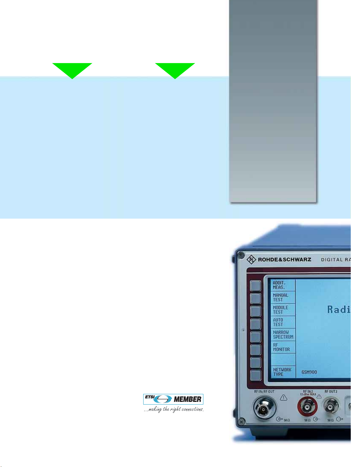
The Digital Radiocommunication Testers CMD have evolved from GSM900
mobile station testers to a fully
equipped test and measurement solution for mobiles and handhelds for all
GSM-based systems as well as DECT.
.... thanks to
continuous innovation
The CMD is the industry standard in
mobile radio testing and defines the
levels that others are judged by. With
extremely high market acceptance
worldwide, the family will stay in the
lead thanks to constant innovation, a
well-chosen modularity through different models and optional extension.
The CMD addresses all aspects of test
and measurement applications from
production and service to development and quality assurance.
Rohde&Schwarz milestones in digital testing
• 1990: CMTA94 – the first test set for GSM transmitter and receiver testing
• 1991: CRTS02/04 – signalling tester for GSM mobile and base stations
• 1992: FTA – sole supplier of the GSM900 system simulator for type-approval
testing of mobiles
• 1993: TA – sole supplier of GSM900 interim type-approval system,
upgradable to GSM1800
• 1996: CRTP/C02 – approved as stand-alone tester for type approval
of phase II GSM900/1800 mobiles
• 1997: supplier of the first type-approval system for GSM1900
Page 3

The family members at a glance
CMD50 – the service tester to suit every budget
• All signalling required for GSM900 testing
• High measurement accuracy and speed
• Autotest and remote control via RS-232-C
• Basic module test features included
• Go/nogo test as well as service mode for exact fault location
CMD53 – service testing for the whole GSM world
• GSM900, GSM1800 and GSM1900
• Testing of handover from GSM900 and back
• Other features as CMD50
CMD52 - the leading GSM900 production tester
• All signalling required for GSM900 testing
• Highest measurement accuracy and speed
• Remote control via IEEE488/IEC625 bus
• Autotest and remote control via RS-232-C
• Go/nogo test as well as service mode for exact fault location
CMD55 – the multiband GSM production tester
• GSM900, GSM1800 and GSM1900
• Testing of handover from GSM 900 and back
• Other features as CMD52
CMD60 – pure DECT dedication
• Compact, lightweight and extremely fast
• Suitable for service, production and development
• Remote control via IEEE488/IEC625 bus + RS-232-C
• Automated regression and stress testing of DUT
• Automatic go/nogo testing of fixed and portable part
CMD65 – the most versatile production tester
• GSM plus DECT in a single box
• Features equal the combination of CMD55 and
CMD60 in almost all respects
The range continues! Please see data sheets for CMD80 series.
Page 4
Manual operation philosophy
Research and development engineers
have found the CMD‘s large clear LC
display and user interface with logically structured menus unsurpassed
when measuring RF parameters. This
is true both in the manual test mode
and in the flexible module test with system-specific signal generator and
burst analyzer. During call setup the
network and system-specific signalling
parameters allow the R&D engineers
to control the influence of signalling
parameters on the mobile´s behaviour
in the network.
quality assurancedevelopment
User-definable autotest
The user-friendly display and operation of the CMD is a main requirement
when testing manually, but for automated testing, the engineer wants a
quick and easy way to a ready-made
autotest or if he has to create his own
test script for the specific task to be
performed. The CMD family of testers
offers different ways of creating such
autotests and test scripts, depending
on the CMD model and the test
requirements.
... meeting the challenges
of modern communications
• Go/nogo tests and comprehensive testing of mobiles
• Powerful signalling capabilities
• Short measurement time
ensuring high throughput
• High measurement accuracy
• Simple interactive operation
•No specialized GSM
knowledge required
• Service mode for exact fault
location
•Autotest – complete mobile
testing at a keystroke
•Very fast remote control
operation
• Compact and lightweight
• Excellent price/performance
ratio
The mobile communications market is
growing beyond anybody’s imagination and the need for testing has therefore become equally demanding.
As the leading manufacturer of type-approval test systems for several worldwide digital wireless standards,
Rohde&Schwarz has succeeded in
combining these standards in one family of instruments, aimed at users in production, service and development.
This data sheet covers the testers for
GSM mobiles as well as for DECT fixed
and portable parts (FP and PP).
The CMD65 – our top model of mobile
testers – combines a number of wellknown key features of the CMD family.
The four most common digital systems
in one instrument, ready at a keystroke,
provide the user with ultimate flexibility.
networks and their configuration
menus, measurements and tests as well
as autotest function.
The CMD53 and the CMD55 offer full
GSM functionality including the handover between GSM bands.
To start out with a single standard, the
Testers CMD50, CMD52 (GSM900)
and CMD60 for DECT applications are
the right choice.
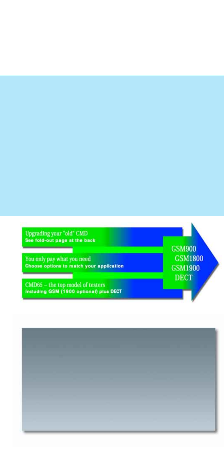
Adding another standard later is no
problem, as the clearly laid-out upgrade path depicted on the back cover
fold-out will demonstrate.
From the main menu, the CMD65 offers
very easy access for up to four digital
2 Digital Radiocommunication Testers CMD
Page 5

A sophisticated product from the market leader
production service
Fast IEEE-bus
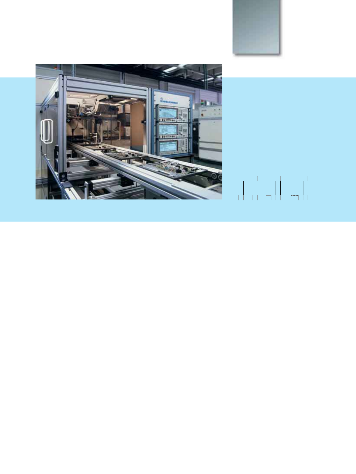
In a production line, there are two
main factors that contribute to high
throughput and product quality: IEEEbus speed and measurement repeatability. The high speed is obtained by
parallel measurements and the possibility to issue multiple commands in a
single IEEE string. With combined
measurements and measurements like
RF peak power which takes only milliseconds, time-consuming power level
adjustments where multiple measurements are required are completed in
seconds. The level of measurement
repeatability offered ensures the highest possible quality of the end product
leaving the factory.
Covering any need for test modes
Service and repair of digital mobiles
and cordless phones call for a variety of
tests, ranging from simple go/nogo tests
to complete factory-like production tests
and calibration of the phone. The CMD
range offers cost-effective solutions for
manual testing, stand-alone autotest, as
well as remote RS-232-C operation solutions covering any need for testing.
Every CMD comes, of course, with the
same large display and user interface
for manual test of phones and/or modules and RS-232-C interface for remote
operation.
Base station survey measurements
These are often performed on real base
stations or by using analog signal generators with power amplifiers. The CMD is
able to simulate any GSM base station
BCCH, including parameters like MCC,
MNC, NCC, BA list, DTX and DRX information. These and the "cell barred" feature enable close-to-life conditions without having to use a real BTS.
Digital Radiocommunication Testers CMD 3
Page 6

Tailored to your application
Through careful design of models and
options, Rohde&Schwarz has devised
a way to ensure you only pay for what
you need. Nearly all the options for
the models offered (see front cover
fold-out) are retrofittable.
The well-defined upgrade path allows
to expand the scope of a new CMD
when you need it (see back cover foldout). Should you already own one –
even first generation CMDs are taken
care of.
Options
The options in detail
Name Description Notes Order No.
CMD-B1 OCXO reference oscillator, aging ±1 x 10⁻⁷. Ensures high absolute accuracy,
minimum temperature-dependent drift and especially high long-term stability.
Used for measurements with exacting requirements on frequency stability.
CMD-B17 I/Q signals from the CMD modulator and burst trigger signals are provided for
the Rohde& Schwarz Signal Generator SMIQ for GSM conformity tests under
fading conditions.
CMD-B19 GSM1900 mobile and base station test. Provides the capability to test
GSM1900 mobiles used on the North American market. Includes factory recalibration of unit .
CMD-B2 High-stability OCXO, aging 3.5 x 10⁻⁸. Oven crystal with highest long-term sta-
bility. Ensures compliance with tolerances specified by GSM. Used for highly
demanding requirements on frequency stability to GSM 11.20.
CMD-B20 GSM-specific voltage and current measurement. Allows readings to be taken in
synchronicity with the GSM pulsed mode.
CMD-B3 Multifrequency reference input/output. For synchronizing DUT and measuring
instrument with internal or external frequencies. Allows synchronization of the
CMD to an internal or external frequency of 2.048, 10, 13, 26, 39, 52 MHz, or
to the GSM bit clock.
CMD-B30 High-level RF output/sensitive RF input. In addition to the normal RF I/O, the CMD
has optionally a high-sensitivity input and a high-level output which enable overthe-air tests on modules or handhelds by means of couplers like the CTD-Z10.
(see also fold-out page on the back)
Cannot be ordered
with CMD-B2
–
For CMD53, 55 as of
serial No. 837176
and CMD65 only
Cannot be ordered
with CMD-B1
Comes as standard in
all models exept
CMD50 and CMD53
–
Comes as standard in
all models exept
CMD50 and CMD53
1051.6002.02
1099.3003.02
1059.6201.02
1059.8604.02
1059.6401.02
1051.6202.02
1059.7308.02
4 Digital Radiocommunication Testers CMD
Page 7

The BER search function allows the absolute sensitivity of a mobile to be
determined
The full dynamic range (>72 dB) of a GSM normal and access burst can be
verified with the CMD-B42 option
The audio measurement option CMD-B44 is capable of generating
and analyzing up to 14 freely configurable tones in about 1 second.
Measurements in absolute and relative mode are possible
After location update, it is indicated whether a mobile is a dual-band version.
For realistic simulation of the real networks, the CMD-U20 offers the option to
have the BCCH present in either band during dual-band simulation
Name Description Notes Order No.
CMD-B4 Fast power ramp, phase/frequency error & BER measurement. Provides fast test-
ing and numeric/graphic display of power bursts and phase / frequency error
as well as various BER, RBER and FER test routines (necessary for Autotest).
Required for options
CMD-B41, CMD-B42,
CMD-B43, CMD-B44
1051.6654.02
and CMD-K43
CMD-B41 Includes audio frequency (AF) generator, voltmeter, distortion meter and fre-
Requires CMD-B4 1051.6902.02
quency counter. Allows measurements on the audio interface or on modules.
Enables frequency measurements up to 60 MHz which is required for LO alignment.
CMD-B42
High dynamic range burst analyzer. Enhances the dynamic range to more than 72
Requires CMD-B4 1051.7150.02
dB and allows the power ramp to be measured in the entire GSM, GSM1800 and
GSM1900 range specified. Determines whether transmitter blanking in inactive
timeslots is correct.
CMD-B43 Carries out GSM measurements of spectrum due to switching and modulation
according to the GSM, GSM1800 and GSM1900 recommendations faster than
Requires CMD-B4 and
CMD-B42
1059.6001.02
any spectrum analyzer.
CMD-B44 Audio multitone option based on DSP techniques. Makes it possible to generate
and measure up to 14 tones in about one second. Useful for loudness rating, fre-
Requires CMD-B4 and
CMD-B41
1099.3203.02
quency response and intermodulation analysis.
CMD-B52 Internal GSM full rate (FR), enhanced full rate (EFR) and half rate (HR) speech
coder/decoder. This option converts digital speech signals into analog signals
and vice versa, allowing separate uplink and downlink audio measurements.
CMD-B6 Adapters for B6x options. Provides GSM-specific signals and trigger signals for
CMD52/55/65 on the multifunction connector at the front of the instrument.
1115.8800.02
–
Required for options
1051.7409.02
CMD-B61 and
CMD-B62
Digital Radiocommunication Testers CMD 5
Page 8

Options (continued)
Options
The option CMD-B43 provides measurements of spectrum due to modulation
and switching according to GSM recommendations
The narrowband spectrum analyzer option CMD-K43 is used to determine the
I/Q modulator balance by measuring the suppressed carrier and sidebands
Name Description Notes Order No.
CMD-B61 IEEE 488 bus interface. Remote control alternative to the RS-232-C interface fit-
ted as standard. Used for fast remote control of the CMD.
CMD-B62 Memory card interface. Allows storage of instrument setups and fast and easy
upgrade to new software features. Highly recommended.
CMD-K43 Narrowband spectrum analyzer. This option is used for narrowband spectrum
analysis (i.e. adjustments of I/Q modulators). Analysis of constant envelope
and burst signals is possible.
Front view of the CMD50/CMD53, the economy CMD52/55 equivalents for use in service
Requires CMD-B6 1051.7609.02
Requires CMD-B6 1051.8205.04
Requires CMD-B4 1082.4830.02
CMD-K61 Frequency extension option covering “DECT Latin America“. For CMD60 and
CMD65.
CMD-K80 Frequency extension option. For CMD5x and CMD65. Additional frequency
range R-GSM.
CMD-U1 Upgrade to GSM multiband functionality. Allows GSM dual-band handover with
CMD53 and CMD55. Conversion of CMD50 into CMD53 and of CMD52 into
CMD55.
CMD-U10 8 MByte memory extension for CPU1 or CPU2. This update allows the use of sev-
eral advanced software features such as GSM dual-band handover, fast BER
measurement (burst-by-burst) and R-GSM band.
CMD-U11 High-speed processor including 8MB RAM. Allows the use of the latest software
versions with the functionality as mentioned in this data sheet and ensures future
updates.
6 Digital Radiocommunication Testers CMD
Requires DECT hardware version E or later
Requires CMD-U10 1082.4930.02
Some mobiles require
the option CMD-U20
to ensure correct dualband handover operation
Only applicable to
older versions of
CMD50, CMD52 and
CMD53, CMD55
For older versions of
CMD52 and CMD55
only
1082.3840.02
1051.8957.02
1059.7908.02
1059.7950.02
Page 9

... you only pay what you need
A member of the CMD family used in an audio
application with the Rohde& Schwarz Audio
Analyzer UPL and artificial ear
Name Description Notes Order No.
CMD-U12 Modification for fast BER (burst-by-burst) capability. For older versions of
CMD52 and 55 only
CMD-U13 10 dB higher sensivity at RF input/output N connector.
RF input level range −10 dBm to +37 dBm instead of 0 dBm to +47 dBm
CMD-U18 Output level of −15 dBm for RF input/output N connector.
RF out 2 becomes non-functional, RF in/out 6 dB more sensitive (max. +40 dBm).
CMD-U19 GSM1900 mobile test. Provides the capability to test GSM1900 mobiles used
on the North American market. Same as CMD-B19 if installation and recalibration can be done at the local Rohde&Schwarz service center.
CMD-U20
CMD-U5 GSM time synchronization signal and demodulated I and Q signals are copied
CMD-U56 Upgrade to support DECT in CMD53/55 multiband testers. Functionality compa-
CMD-U61 Frequency extension upgrade covering “DECT Latin America“. For CMD60 and
A special RF converter for the CMD53/55 enables handover between GSM900
and GSM1800/1900 while maintaining the BCCH in the band (lower/upper) in
which the handover was initiated. Standard in the current version of the CMD55.
from the multifunction connector to three BNC connectors at the rear panel.
rable to that of CMD65.
CMD65.
Only for GSM signals 1059.4009.02
Only for GSM signals 1099.5358.02
For CMD53, 55 as of
serial No. 837176
and CMD65 only
For older CMD53 in
conjunction with
CMD-U10 only.
Not compatible with
CMD60/65 and
instruments with
upgrades CMD-U56
and CMD-U65.
Factory installation.
See under CMD-U5.
Factory installation.
For D version hardware only. Factory
installation.
1059.4150.02
1099.5458.02
1099.5606.02
1059.6901.02
1059.8004.02
1099.5258.02
CMD-U65 GSM multiband upgrade for CMD60. Functionality comparable to that of
CMD65.
Factory installation. 1059.8104.02
Digital Radiocommunication Testers CMD 7
Page 10
DECT measurements
CMD60
CMD65
The CMD60 is the Rohde&Schwarz
one-box DECT tester, whereas the
CMD65 offers GSM functionality
alongside DECT
Frame number
15 0 1
16 23 0 22 23 22 23
Slot number
Interface description
CMD 60/65 transmitter part
In a very busy DECT environment,
most DECT frequencies may be in use
for communication and therefore influence the measurement in production
and development. Besides the channels 0 to 9 the CMD enables the use of
an extended frequency range for testing. The channels −3, −2, −1 and 10,
11, 12 are outside the normal DECT
specification and therefore free for
testing. Up to 35 channels are available with options CMD-U61 and
CMD-K61 (channels +12 to −22).
The wide amplitude range of the RF
level provides a comfortable compensation for attenuation in external coupling devices.
The CMD enables the use of up to 6
TDMA slots for rapid BER measurements for PP test (2 slots for FP test). A
very short measuring time for production can be achieved with the use of
more than one timeslot for BER measurements if supported by the unit
under test.
The modulation is GFSK with B x T =
0.5 according to DECT specifications.
In addition, constant envelope, signals
with or without modulation or DECT
bursts with various bit patterns for
module testing are possible. These bit
patterns can easily be recognized
while testing receiver and demodulator modules.
CMD 60/65 receiver part
It is similar to the transmitter part above.
There are 10 DECT frequencies, 0 to 9.
Additionally, the 6 extended DECT frequencies −3, −2, −1 and +10, 11, 12 in
half DECT channel spacing are pro-
vided. Up to 35 channels are available
with the options CMD-U61 and CMDK61 (channels +12 to −22).
The modular concept of the CMD also
allows the Latin American frequency
extension to be added (see CMD-K61
and CMD-U61 in the options section).
The sensitivity of the CMD60 ensures
valid measurement results even with
compensation for attenuation in external coupling devices.
There are two independent receive
paths: For DECT signalling and BER, a
signalling path is provided. For TX
tests, the CMD60 provides a measurement path. The signals from the FM
and envelope detector are taken to
external connectors and post-processed for power ramp and modulation measurements. The FM and envelope detector output permits monitoring of the DUT transmit signal.
8 Digital Radiocommunication Testers CMD
Page 11

Benefits in ...
... production
• The CMD60/65 is remote-controllable via RS-232-C or IEC/
IEEE-bus interface using the
SCPI-compatible commands. In
the remote-control mode, the
CMD is designed for fast speed
to yield high throughputs in production
• High production output versus
low investment for test equipment
• Comprehensive flexible autotest
capabilities make the CMD60/
65 a one-box DECT solution
RF in/out configuration
Transmitter and receiver are connected to a bidirectional N connector
(RF in/out). All specifications mentioned are valid for this connector.
Moreover, there is a high-level output
for the CMD transmitter and also a
sensitive input for the CMD receiver on
the front panel. These connectors
together with an external power splitter/combiner can be used to shift the
level range of the N connector (for
details on differences between the
CMD60 and CMD65 see specifications).
Demodulation interface
The CMD 60/65 provides a linear
analog FM demodulator output (DC
coupled) and a logarithmic analog RF
envelope demodulator output.
Wideband in/out
The secondary wideband input/output
is at the rear panel. The input signal
... development
• Comprehensive in-depth measurements of specifications via a
convenient manual user interface
• A lot of complex test setups required with conventional equipment become redundant thanks
to this special DECT tester
• Automated regression tests and
stress tests
• The tester supplies a large
number of DECT-specific signals for the control of the module under test
from the front connector is available at
this connector with an attenuation of
18 dB. It can be monitored with a spectrum analyzer for spurious measurements. Furthermore, this connector can
be utilized to introduce an interferer into
the RF connection without reconnecting
the test setup for the in-channel tests. This
input/output can be used from
100 MHz to 2.5 GHz.
Audio part
In addition to the DECT RF interface on
the CMD60 front panel, there is an analog DECT speech interface for speaker
and appropriate microphone on the
rear panel (analog ADPCM interface).
Alternatively, it can be internally connected to the AF measurement port.
... servicing
• Rapid go/nogo results using the
autorun function
• Relaxed manual operation due
to a large bright LCD in conjunction with an extremely simple user interface (requires no
DECT-specific knowledge) strictly separated from the expert user interface for configurations
• Integrated tools such as a scope
display for power versus time
and FM demodulation versus
time ease troubleshooting
Trigger
DECT measurements are alternatively
triggered under the following conditions:
– RF rising slope
– External trigger event
– Internal trigger, time reference is bit
P0 (standard)
Time synchronization
The CMD60 provides DECT-specific
timing signals (frame clock, RS485)
which can be routed to other CMDs if
the CMD is the master. If the CMD is
declared slave, it will synchronize to
this signal. This way several PPs, e.g.
on a production line, can be tested at
several CMDs in parallel without any
mutual interference.
Additional DECT-specific signals
1152 kHz bit clock output, alternatively
multiples: 3,456, 6,912 and
13,824 MHz and fractions:
576, 288, 144 kHz.
Digital Radiocommunication Testers CMD 9
Page 12

Up to date by simply upgrading
Early-stage CMD52 with
CPU1 or CPU2 and
4 MByte internal RAM.
CMD-U11
The early-stage CMD52
is thus comparable to
today´s state-of-the-art
GSM900 tester, with
test and measurement
specifications as stated
in this data sheet. From single band to multiband
CMD-U1
From early-stage to state-of-the-art performance
The CMD-U11 upgrade includes our currently fastest processor CPU3a and 8 Mbyte internal RAM. This ensures future
software updates and the possibility to use all the latest test
and measurement features and provide the fastest IEC/IEEE
bus on the market.
The CMD-U1 hardware upgrade will convert the
CMD52 into a CMD55, with the possibility to test
GSM1800, GSM1900 (with CMD-U19) as well as
GSM900 mobiles.
This CMD is now
equivalent to the
standard CMD55
mentioned in this
data sheet, newly
calibrated and able
to be customized
with options as
listed.
Unsurpassed test capabilities
and measurement speed. All
this at incredibly low weight
and without any bulk.
Since the development of the first
CMD5x, it has been the philosophy of
Rohde&Schwarz to ensure that all
CMD5x users can upgrade their instruments to the current state of the art.
10 Digital Radiocommunication Testers CMD
CMD-U56
Any CMD5x mobile tester can be
upgraded to a full-blown CMD with
four digital networks in one instrument, ready at a keystroke. The chart
above shows how to upgrade from an
early-stage CMD5x mobile tester to
the present level of performance and
From multiband to multimode
The CMD-U56 hardware upgrade enhances the functionality of the CMD55 to the functionality of a CMD65. The
CMD55M (multimode) is now able to cover all official GSM
systems as well as all official DECT bands. *)
functionality. It also shows that acquisition of a single-network CMD tester
today does not restrict the user to the
original application – thanks to the
unique Rohde&Schwarz upgrade
path!
*) Likewise, the CMD-U65 allows the CMD 60 to be
enhanced to CMD 65 functionality.
Page 13

Models and options
Service
High-end
service
Production
CMD50 J ✘ – ✘
CMD53 J ✘ – ✘
CMD52 ✘ J J J
CMD55 ✘ J J J
CMD60 ✘ J J J
CMD65 ✘ J J J
High-end
service
Production
Develop-
ment & QA
✘
–
CMD50
CMD53
CMD52
CMD55
CMD60
CMD65
CMD-B1 2)
CMD-B2 2)
CMD-B3
CMD-B4
CMD-B51
CMD-B6
CMD-B17
CMD-B41
CMD-B42
CMD-B43
CMD-B44
CMD-B61
CMD-B62
CMD-K43
CMD-U5
CMD-U10
CMD-U11
CMD-U13
CMD-U18
CMD-U20
CMD-Z1
✘
✘
–
✘
J
J
J
J
J
J
J
J
J
J
J
J
✘
✘
✘
J
✘
J
✘1)
J
J
J
J
J
J
J
J
J
J
J
✘
✘
J
J
J
J
J
J
J
J
J
J
J
J
J
–
J
J
J
J
J
J
J
J
✘
–
J
✘
–
–
J
J
J
✘
✘
J
J
✘
J
✘
J
J
J
J
J
1 3
CMD52
CMD55
CMD60
CMD65
+
+
+
Development
& QA
2
Service
J
J
✘
✘
✘
✘
J
✘
✘1)
J
✘
✘
✘
✘
✘
✘
✘
–
J
✘
✘
✘
J
✘
✘
✘
J
CMD-B1 2)
CMD-B2 2)
CMD-B3
CMD-B4
CMD-B52
CMD-B6
CMD-B17
CMD-B19
CMD-B20
CMD-B30
CMD-B41
CMD-B42
CMD-B43
CMD-B44 8)
CMD-K43
CMD-B61
CMD-B62
CMD-K61
CMD-K80
CMD-U1
CMD-U5
CMD-U10
CMD-U11
CMD-U12
CMD-U13 6)
CMD-U18 6)
CMD-U19
CMD-U20
CMD-U56
CMD-U61
CMD-U65
CMD-Z1
3
+
–
+
+
+
+
+1)
+
●
●
+
+1)
+1)7)
+
+1)9)
+
+
+3)
+
–
–
–
●
●
+
+
+
+
●
+4)
●
+
●
●
+3)
●
+4)
+
+
–
+
+
+
+
+
+
+
+
–
+
+
+
+
+
–
–
+
–
●
●
●
●
+
+
+
+
+
–
–
+7)
+7)
+
+
+
–
+9)
+9)
+
+
+
+
+
+
–
–
+
+
–
+
–
–
+
+
–
–
–
–
●
●
●
●
–
–
+
–
–
+
–
–
+
–
–
●
–
–
+
+
+10)
–
+
–
–
–
–
+
+
CMD53
+
+
+
+
–
+5)
–
+
+
+
+
+
+7)
+
+9)
–
+
–
+
–
+
●
–
–
+
+
+
+
–
–
+
CMD50
+
+
+
+
–
+5)
–
–
+
+
+
+
+7)
+
+9)
–
+
–
+
+
+
●
–
–
–
–
–
–
–
–
–
+
Tabl e 1
Applications and
instruments
Tabl e 2
Recommended instruments
and options
Tabl e 3
Combinations of instruments
and options
Comments on Table 2:
highly recommended
J
✘ recommended
– not recommended
1
) External frequency reference may be
used, if available.
2
) One of two OCXOs should be installed
to ensure high frequency accuracy.
Comments on Table 3:
+
possible
– not possible
● standard
1
) Only for GSM applications.
2
) CMD-B1 or CMD-B2 possible.
3
) Only with DECT module version E.
4
) Only with DECT module version D.
5
) Multifunction connector not
available on CMD50/53.
6
) CMD-U13 or CMD-U18 possible.
7
) CMD-B4 and CMD-B42 required.
8
) CMD-B4 and CMD-B41 required.
9
)CMD-B4 required.
10
) CMD-U10 required (previous models).
Note:
The CMD-B4 option is a prerequisite for all
CMD-B4x and CMD-K4x options.
The CMD-B6 option is a prerequisite for all
CMD-B6x options.
Digital Radiocommunication Testers CMD 11
Page 14

Specifications of CMD50/52
GSM specifications of CMD53/55/65
RF generator 1
Frequency range GSM900 band:
Frequency error same as time base
Resolution GSM channel spacing: 200 kHz
Frequency setting time
Output level (RF IN/OUT) −33 dBm to −120 dBm
Resolution 0.1 dB
Level error (RF IN/OUT)
Harmonics (RF IN/OUT) <
Modulation GMSK, B x T = 0.3
Phase error
RF generator 2
Frequency range, frequency error,
resolution, setting time, level
resolution, harmonics, modulation
and phase error see RF generator 1
Maximum output level
RF IN/OUT
RF OUT 2 +11 dBm
Level error
RF IN/OUT
RF OUT 2
Peak power meter (RF IN/OUT)
Frequency range 800 MHz to 1000 MHz
Measurement range 10 dBm to 47 dBm
Resolution 0.1 dB
Error in GSM band
890.2 MHz to 914.8 MHz
VSWR
GSM phase and frequency error
measurement with option CMD-B4
Frequency range GSM900 band:
Level range
RF IN/OUT 10 dBm to 47 dBm
RF IN 2
Inherent phase error <1.5
Frequency measurement error <5 Hz + time base
GSM burst power measurement with option CMD-B4
Frequency range GSM900 band:
Reference level for full
dynamic range
RF IN/OUT 10 dBm to 47 dBm
RF IN 2
Absolute measurement error of
peak power
RF IN/OUT see peak power meter
RF IN 2
Resolution in active part of
timeslot 0.1 dB
Burst analysis
with wide dynamic range with option CMD-B42
Relative error of individual
test sample
Dynamic range >72 dB
Measurement limit RF IN/OUT <
(RF OUT 2) +13 dBm to
(RF OUT 2)
Measurement limit RF IN 2 <
1
The maximum RF output level of the CMD65 in the GSM900/1800/
935.2 MHz to 959.8 MHz
≤3 ms for phase error <2°
−77 dBm
≤1.5 dB (≤1dB at −104 dBm)
≤2dB
−30 dBc
≤4° rms, ≤10° peak
−35 dBm
≤1.5 dB
≤2dB
≤0.5 dB + resolution (P >13 dBm)
≤1.3
890.2 MHz to 914.8 MHz
−60 dBm to 0 dBm
° rms, <5° peak
890.2 MHz to 914.8 MHz
−37 dBm to 0 dBm
≤1 dB
≤1.5 dB to 72 dB below peak power
−36 dBm
−83 dBm
1900
band is 2 dB lower than in the CMD5x basic unit
2
In GSM1900 mode with option CMD-B19/-U19 fitted.
3
The sensitivity of the CMD65 in the GSM900/1800/1900 band is 2 dB
lower than in the CMD5x basic unit.
12 Digital Radiocommunication Testers CMD
RF generator 1
Frequency range
GSM900 935.2 MHz to 959.8 MHz
GSM1800 1805.2 MHz to 1879.8 MHz
GSM1900
Frequency error same as time base
Resolution GSM channel spacing: 200 kHz
Frequency setting time
Output level
RF IN/OUT
RF OUT 2
Resolution 0.1 dB
Level error RF IN/OUT
Harmonics (RF IN/OUT) <
Modulation GMSK, B x T = 0.3
Phase error
RF generator 2
Frequency range, frequency error,
resolution, setting time, level
resolution, harmonics, modulation
and phase error see RF generator 1
Maximum output level
RF IN/OUT
RF OUT 2
Level error
RF IN/OUT
RF OUT 2
Peak power meter (RF IN/OUT)
Frequency range 800 MHz to 1000 MHz,
Measurement range
GSM900 band 0 dBm to 47 dBm
GSM1800/1900 band 0 dBm to 33 dBm
Resolution 0.1 dB
Error in GSM900 band
Error in GSM1800/1900 band
VSWR
Phase/frequency error measurement with option CMD-B4
Frequency range
GSM900 890.2 MHz to 914.8 MHz
GSM1800 1710.2 MHz to 1784.8 MHz
GSM1900
Level range
RF IN/OUT GSM900: 0 dBm to 47 dBm
RF IN 2
Inherent phase error <1.5
Frequency measurement error <5 Hz + time base
Burst power measurement with option CMD-B4
Frequency range
GSM900 890.2 MHz to 914.8 MHz
GSM1800 1717.2 MHz to 1784.8 MHz
GSM1900
Reference level for full dynamic range
RF IN/OUT GSM900: 10 dBm to 47 dBm
RF IN 2
Absolute measurement error of
peak power
RF IN/OUT GSM900:
RF IN 2 GSM900:
Resolution in active part of timeslot 0.1 dB
Burst analysis with high
dynamic range with option CMD-B42
Relative error of individual test
samples
Dynamic range >72 dB
Measurement limit RF IN/OUT GSM900: <
Measurement limit RF IN 2
1)
2)
3)
2)
1930.2 MHz to 1989.8 MHz
≤3 ms for phase error <2°
1)
RF OUT 2
−35/−37
+11/+92) dBm to −77 dBm
≤1.5 dB (≤1dB at −104 dBm)
≤2dB
dBm to −120 dBm
2)
−30 dBc
≤4° rms, ≤10° peak
2)
1)
+9/+72) dBm
−37/−39
≤1.5 dB
≤2dB
dBm
1700 MHz to 2000 MHz
≤0.5 dB + resolution (P >10 dBm)
≤0.8 dB + resolution (P >4 dBm)
≤1.3
2)
1850.2 MHz to 1909.8 MHz
3)
−60/−542) dBm to 0 dBm
GSM1800/1900: 0 dBm to 33 dBm
° rms, <5° peak
2)
1850.2 MHz to 1909.8 MHz
3)
−37/−312) dBm to 0 dBm
GSM1800/1900: 0 dBm to 33 dBm
≤0.5 dB + resolution
(P>10 dBm)
GSM1800/1900:
tion (P >4 dBm)
GSM1800/1900:
≤1.3 dB
≤0.8 dB + resolu-
≤1.5 dB
≤1.5 dB to 72 dB below peak power
−36 dBm
GSM1800: <
GSM1900
3)
GSM900: <−83 dBm
GSM1800: <
GSM1900
−48 dBm
2)
: <−42 dBm
−85 dBm
2)
: <−79 dBm
Page 15

GSM specifications of CMD50/52/53/55/65
GSM-specific spectrum
measurements
Spectrum due to modulation
Test method relative measurement, averaging
Filter bandwidth 30 kHz resolution filter
Measurement at an offset of 100, 200, 250, 400, 600, 800, 1000,
Dynamic range better than required by GSM specifi-
with offset >400 kHz max. 80 dB
Error
Spectrum due to switching
Test method absolute measurement, Max Hold
Filter bandwidth 30 kHz resolution filter
Measurement at an offset of 400, 600, 1200, 1800 kHz
Dynamic range better than required by GSM specifi-
for offset >400 kHz 80 dB max. with SW correction,
Error
with option CMD-B43
1200, 1400, 1600 and 1800 kHz
cation
≤1.5 dB
over several measurements
cation
76 dB max. without SW correction
≤1.5 dB (dynamic range <50 dBc)
≤2.5 dB (dynamic range 50 to 80 dBc)
DECT specifications of CMD60/65
DECT signal generator
Frequency 1876.608 MHz to 1935.360 MHz,
Error same as reference
Level range
RF IN/OUT
RF OUT2 –40 dBm to +5 dBm (
Burst switch-off >30 dB
Resolution 0.1 dB
Error
RF IN/OUT
RF OUT2
Modulation GFSK (B x T=0.5)
Error <5% (at 288 kHz deviation)
DECT analyzer specifications are valid for N connector
Frequency same as signal generator
Level (matching setting for external
attenuation and expected
power)
RFIN/OUT 30 dBm to
RFIN2
FM demodulator for TX postprocessing and
Range 0 kHz to 450 kHz deviation
Resolution 1 kHz
DC offset <2 kHz
Residual deviation
RF IN/OUT <15 kHz PK, 95% confidence
RF IN2 <15 kHz PK, 95% confidence
4)
5)
half channel spacing
−100 dBm to −40 dBm
+5 dBm when RF IN2 is active)
usable up to 7.5 dBm
<1.5 dB
<2.0 dB
30 dBm to
FM demodulator and signalling)
−35 dBm to −85 dBm (for level meter)
−11 dBm to −55 dBm (for broadband
FM, demodulator and signalling)
analog output
(+30 to –30 dBm),
<5 kHz PK, 95% confidence
(+30 to –10 dBm)
(–11 dBm to –55 dBm),
<5 kHz PK, 95% confidence
(–11 dBm to –40 dBm)
−65 dBm (for level meter),
−30 dBm (for broadband
−20 dBm to
Analog output 1 V p
Level meter (transient response) for TX postprocessing and analog
Range
RF IN/OUT +30 dBm to
RF IN2
Dynamic 70 dB (24 dBm at RFIN/OUT)
Resolution 0.5 dB
Error
RF IN/OUT
RF IN2
Analog output 28.3 mV/1 dB, 2.5 V at +30 dBm
Analog DECT ADPCM interface
Output balanced
Range 558 mV with 0 dBm0 on the PCM inter-
Impedance 10
S/N + THD 35 dB at full-range level
Passband ripple 0.5 dB
Input balanced
Range 40 mV for 0 dBm0 on the PCM inter-
Impedance 125 k
S/N + THD 35 dB at full-range level
Passband ripple 0.5 dB
DECT applications averaging 10,
Accuracy and stability of RF carrier
Error <2 kHz + reference
Accuracy and stability of timing
Error <0.075
Modulation part 1, 2, 4
Error approx. 11 kHz at minimum (202 kHz)
Frequency drift
Error approx. 1 kHz/ms
Normal transmit power
Error
Power versus time
Error power
6)
7)
time <0.075
for 500 kHz deviation (linear)
output
−35 dBm to −85 dBm
≤1.5 dB + resolution
(+30 dBm to +15dBm)
≤2 dB + resolution in rest of range
≤2 dB + resolution
(
−35 dBm to −51dBm)
≤2.5 dB + resolution in rest of range
(standard internal attenuator setting),
logarithmic
face, 300 Hz to 3 kHz
face, 300 Hz to 3 kHz
specs are valid for RFIN/OUT
approx. 13 kHz at maximum (403 kHz)
permitted deviation
≤1.5 dB
≤1.5 dB, 30 dBm to 5 dBm,
≤2 dB in rest of range
−65 dBm
Ω typ.
Ω typ.
µs + reference
µs + reference
4)
Frequency response ±0.2 dB typ.
Linearity
Drift
5)
Frequency response ±0.5 dB typ.
Linearity
Drift
±0.3 dB typ.
±0.3 dB typ.
±0.4 dB typ.
±0.5 dB typ.
6)
)
Frequency response typ.
Linearity typ.
Drift typ.
7)
)
Frequency response typ.
Linearity typ.
Drift typ.
Digital Radiocommunication Testers CMD 13
±0.5 dB typ.
±0.3 dB typ.
±0.5 dB typ.
±0.5 dB typ.
±0.5 dB typ.
±0.5 dB typ.
Page 16

Common specifications
DC voltmeter for CMD50/53 as an option (CMD-B20)
Measurement range 0 V to
Resolution 10 mV
Error
DC ammeter for CMD50/53 as an option (CMD-B20)
Operating modes current averaging with GSM-adapted
Measurement range 0 A to
Common-mode rejection
Resistance 50 m
Resolution for current averaging 1 mA/10 mA
Resolution for peak measurement 10 mA
Residual indication
(no current at input)
Error
AF Measurement Unit option CMD-B41
AF generator
Frequency range 50 Hz to 10 kHz
Frequency resolution 0.1 Hz
Frequency error same as time base + half resolution
Level range 10
Level resolution 10
Level error
Distortion
Max. output current 20 mA
Output impedance <5
AF voltmeter
Frequency range 50 Hz to 10 kHz
Measurement range 0.1 mV to 30 V
Resolution 100
Error
Input impedance 1 M
Distortion meter
Frequency range 300 Hz to 3 kHz
Input level range 100 mV to 30 V
Resolution 0.1% distortion
Inherent distortion
Error
Measurement bandwidth 10 kHz
AF counter
Frequency range 20 Hz to 10 kHz
Input level range 10 mV to 30 V
Resolution
Error same as reference + resolution
Input impedance 1 M
IF counter
Frequency range 10 kHz to 60 MHz
Input level range 100 mV (rms) to TTL
Resolution 1 Hz
Error same as reference + resolution
Input impedace approx. 1 M
±30 V
≤2% + resolution
time constant, current peak measurement (maximum and minimum)
±10 A
±30 V
Ω
≤10 mA (at room temperature, com-
mon mode rejection voltage ±10 V)
≤2% + residual indication + resolution
µV to 5 V
µV at <1 mV
1% at
≥1 mV
≤5% at ≥1 mV
≤0.5%
Ω
µV at <10 mV
1% at
≥10 mV
≤5% + resolution
Ω
≤0.5%
≤5% + inherent distortion
≤1 Hz
Ω
Ω 100 pF
Time and frequency reference
Time base TCXO standard
Nominal frequency 10 MHz
Max. frequency drift in
temperature range 5°C to 35°C
≤1.5 x 10
−6
Deviation due to aging ≤0.5 x 10⁻⁶ per year (at 35°C)
Time base OCXO, version 1 option CMD-B1
Nominal frequency 10 MHz
Max. frequency uncertainty in
temperature range 5°C to 45°C ±1 x 10
Deviation due to aging (after
30 days of operation and under
constant operating conditions)
≤ 5 x 10
≤2 x 10
−7
−9
per day or
−7
per year
Warm up time approx. 5 min at room temperature
Time base OCXO, version 2 option CMD-B2
Nominal frequency 10 MHz
Max. frequency uncertainty in
temperature rannge 5°C to 45°C
(referred to 25°C)
Deviation due to aging
(after 30 days of operation and under
constant operating conditions)
Warmup time (at 25°C) approx. 10 min
Reference frequency inputs/outputs option CMD-B3
Synchronization input:
Frequency (selectable) GSM bit clock (270.8 kHz), 2/4/16
External reference, nominal
Frequency (CMD60) 10 MHz
Input impedance 100
−9
≤5 x 10
−10
−8
per year
per day
≤3.5 x 10
≤5 x 10
times GSM bit clock, 1 MHz to 13 MHz
in 1 MHz steps, 2.048, 26, 39, 52 MHz
Ω
Input voltage range 632 mV (pp) to 5 V (pp)
Synchronization output 1:
Frequency 10 MHz with internal reference or fre-
Voltage 5 V (pp), R
quency at synchronization input with
external reference
= 50 Ω (10 MHz signal)
out
Synchronization output 2:
Frequency (selectable) GSM bit clock, 2/4/16 times GSM bit
Voltage 5 V (pp), R
Interfaces
IEEE/IEC-bus interface option CMD-B61
Other interfaces RS-232-C (9-contact)
clock, 1, 2, 4 or 13 MHz
interface to IEC 625-1/IEEE 488,
SCPI-compatible command set
out
= 50 Ω
Centronics (25-contact)
General data
Operating temperature range 5°C to 45°C to DIN IEC 68-2-1/2
Storage temperature range
Electromagnetic compatibility meets European EMC directive
Mechanical resistance
Sinusoidal vibration to DIN IEC 68-2-6, 5 Hz to 55 Hz,
Random vibration to DIN 40046, part 24, 10 Hz to
Shock to MIL-STD-810 D, 400 m/s
Power supply 90 V to 265 V, 45 Hz to 440 Hz
Power consumption CMD 55: approx. 95 W
Electrical safety VDE 0411, class 1
Dimensions (W x H x D) 435 mm x 192 mm x 363 mm
Weight (without options) CMD 55: approx. 14 kg
−40°C to +60°C
(89/336/EEC)
amplitude 0.15 mm, two cycles
2
300 Hz, 10 m/s
shock spectrum in 6 main axes
CMD 60: approx. 60 W
CMD 65: approx. 100 W
CMD 60: approx. 12 kg
CMD 65: approx. 17 kg
rms, 5 min/axis
2
,
14 Digital Radiocommunication Testers CMD
Page 17

Ordering information
Digital Radiocommunication Tester CMD 50 1050.9008.50
Accessories supplied power cord, operating manual, fuses
Calibration with Certificate CMD-DCV2 0240.2193.08
Recommended extras
GSM GPRS Test SIM Card
(essential for BER measurements) CRT-Z2 1039.9005.02
Formatted Memory Card
(CMD-B62 required) CMD-Z1 1059.5305.02
Handset CMD-Z50 1059.4250.02
Antenna Coupler CMU-Z10 1150.0801.02
Shielded Chamber for CMU-Z10 CMU-Z11 1150.1008.02
Rackmount Adapter ZZA-94 0396.4905.00
For further CMD models ask your local representative
CMD 53 1050.9008.53
CMD 52 1050.9008.52
CMD 55 1050.9008.05
CMD 60 1050.9008.60
CMD 65 1050.9008.65
Different specifications for CMD53/55/65 with
CMD-U13
The RF input 1 of the CMD53/55/65 with CMD-U13 is 10 dB more sensitive.
Therefore the following specifications differ from those of an unmodified CMD
Peak power meter (RF IN/OUT)
Measurement range
Maximum RF power +37 dBm
Error in GSM900 band
Error in GSM1800/1900 band
Phase and frequency error measurement
Level range (RF IN/OUT)
Burst power measurement
Reference level range for full
dynamic range (RF IN/OUT)
GSM900: 0 dBm to +37 dBm
GSM1800/1900:
The CMD53/55/65 with CMD-U13 have a different output level range at RF OUT 2
RF generator 1
Output level range (RF OUT 2)
RF generator 2
Output level range (RF OUT 2)
Certified Environmental System
−10 dBm to +37 dBm
≤0.5 dB + resolution (P >−6 dBm)
≤0.8 dB + resolution (P >−6 dBm)
−10 dBm to +37 dBm
−10 dBm to +37 dBm
8)
−35 (−37
−37 (−39
) dBm to −120 dBm
8)
) dBm to −120 dBm
Certified Quality System
Different specifications for CMD53/55/65 with
CMD-U18
RF generator 1 (TCH)
Output level range (RF IN/OUT)
Level error (RF IN/OUT)
RF OUT 2 not available
RF generator 2 (BCCH)
Output level range (RF IN/OUT)
Level error (RF IN/OUT)
RF OUT 2 not available
Analyzer
Level range (RF IN/OUT) 0 dBm to 40 dBm
Error peak power meter GSM900: ≤0.5 dB + resolution
−120 dBm to −15/−17
≤
2 dB
−
15/−172) dBm to −35/−378) dBm)
(
≤
1.5 dB (−35/−372) dBm to −120 dBm)
≤
1.0 dB (at −104 dBm)
−120 dBm to −17/−19
≤2 dB
GSM1800/1900:
8)
dBm
8)
dBm
≤
0.8 dB + resolution
Different specifications for CMD53/65 with
CMD-U20
Combined mode (BCCH and TCH in different GSM bands)
Level error of synthesizer 1
RF IN/OUT <3 dB
RF OUT 2 <3 dB
Level error of synthesizer 2
RF IN/OUT <3 dB
RF OUT 2 <3 dB
ISO 14001
REG. NO 1954
ISO 9001
DQS REG. NO 1954
8)
In GSM1900 mode with option CMD-B19/-U19 fitted.
Digital Radiocommunication Testers CMD 15
Page 18

Printed in Germany 1201 (Bi as)
Data without tolerances: typical values
⋅
Subject to change
⋅
ROHDE& SCHWARZ GmbH & Co. KG ⋅ Mühldorfstraße 15 ⋅ 81671 München ⋅ Germany ⋅ P.O.B. 801469 ⋅ 81614 München ⋅ Germany ⋅ Telephone +49 89 4129-0
www.rohde-schwarz.com
⋅ Customer Support: Tel. +49 1805124242, Fax +49 89 4129-13777, E-mail: CustomerSupport@rohde-schwarz.com
Trade names are trademarks of the owners
⋅
Digital Radiocommunication Testers CMD
⋅
PD 0757.2596.23
 Loading...