

Page 1
ROGUE TERRAIN
OFF GRID POWER SUPPLY ENCLOSURE
Installation and Operation Guide
Overview .....................................................2
Device Options ...............................................3
Installation .....................................................4
External Power Wiring ..........................................4
Power Wiring Test .............................................5
Specications .................................................6
Wiring Diagram ...............................................7
Interior Pictorial ...............................................8
3860 S. Jason Street
Englewood Colorado 80110
www.rogue-engr.com
Toll Free 1-800-364-0659
Phone 303-734-0706
Fax 303-734-0517
Page 2

ROGUE TERRAIN
OFF GRID POWER SUPPLY ENCLOSURE
OVERVIEW
The Rogue Terrain packaged charge controller consists of a powder-coated
steel equipment enclosure with a hinged latching cover that includes a Rogue
Engineering 5 Amp or 10 Amp solar battery charger, an optional 15 Amp
Low Voltage Disconnect (LVD) device, mounting space and a retainer for a
customer-provided 12 Volt 12 Amp Hour (AH) battery and associated fuse
and wiring distribution blocks. All electronic devices within the controller
are DIN rail mounted. Approximately eight (8) inches of open DIN rail space
is available within the enclosure for the customer’s use in mounting their
unique equipment.
Three weather-proof cable grips are provided in the bottom of the enclosure
to provide secure egress for battery, solar and output / load wiring.
Battery, Solar and Load wiring connection points on appropriate DIN rail
mounted through- and fuse- blocks are clearly identied.
A .25 inch round opening, normally protected with a plastic plug, is oered
on the upper right side of the enclosure to allow the mounting of a customerprovided antenna if radio equipment is to be placed in the customer
equipment space.
If the controller is to be used with a customer-provided internal battery, the
battery will be securely mounted in the base of the enclosure utilizing a nylon
strap / buckle retainer.
Battery charging capacity is limited to 5 Amps or 10 Amps depending upon
which charge controller is utilized and is protected at those levels by the Solar
and Battery fuses which will be sized at 5 Amps or 10 Amps accordingly.
The Load output, regardless of whether or not the optional Low Voltage
Disconnect (LVD) device is utilized is limited to and fused at 15 Amps and is
independent of the 5 Amp or 10 Amp battery charging fuse. This allows the
Rogue Terrain, even if limited to a 5 Amp or 10 Amp charge current rate, to
provide an output of up to 15 Amps for a limited period of time. It must be
recognized that depletion of the battery through a prolonged high current
load will signicantly impact the 5 Amp or 10 Amp recharge interval.
Note that although the 5 Amp charger label identies it as a 6 / 12 VDC device
and the 10 Amp charger label identies it as a 12 / 24 VDC device the Rogue
Terrain “500 and 1000 Series’’ are designed for 12 VDC operation only.
2 ROGUE TERRAIN OFF GRID POWER SUPPLY ENCLOSURE
Page 3

DEVICE OPTIONS:
The Rogue Terrain series includes four unique models:
– Rogue Terrain 500
– Rogue Terrain 515
– Rogue Terrain 1000
– Rogue Terrain 1015
The four models are characterized as follows:
Top Level
Part Number
1950-273 ROGUE TERRAIN 500-
Description Extended
Description
1950-136,
Rogue Enclosure
NO LVD
Charger
Type
Charger
Rogue
Part
Number
LVD
Type
LVD
Rogue
Part
Number
5A 1950-136 NO LVD N/A
w/5A Charger
1950-274 ROGUE TERRAIN 515-
Rogue Enclosure
1950-136, &
1950-222
5A 1950-136 15A 1950-
222
w/15A LVD
1950-275 ROGUE TERRAIN 1000-
Rogue Enclosure
1950-253,
NO LVD
10A 1950-253 NO LVD N/A
w/10A Charger
1950-276 ROGUE TERRAIN 1015-
Rogue Enclosure
1950-253, &
1950-222
10A 1950-253 15A 1950-
222
w/15A LVD
The Rogue Terrain may be provisioned with or without an integral Low Voltage
Disconnect (LVD) device.
In addition, the device may be provisioned with or without a customerprovided internal battery. If an external battery is used, it is to be wired to the
same terminal block locations as are used with the internal battery.
ROGUE TERRAIN OFF GRID POWER SUPPLY ENCLOSURE 3
Page 4

INSTALLATION
The Rogue Terrain enclosure may be wall mounted or pole mounted.
If wall mounted the device shall be secured to the wall utilizing appropriate
customer-provided mounting apparatus.
If pole mounted, the slots in the anges at the top and bottom of the enclosure
will accommodate a variety of sizes of U-bolts that may be used with a round
pole.
EXTERNAL POWER WIRING
Ensure that the Battery, Solar and Load fuses are removed from the
corresponding three black DIN mounted fuseholders.
External battery, solar and load wiring should use, at minimum, AWG 14
stranded copper wire and industry convention would dictate that all external
positive wiring should be red and negative (ground) wiring should be black.
Extend red and black wires from solar panel(s) into the rear cable grip at the
bottom of the enclosure and terminate on the designated Solar (+) and Solar
(-) terminals as identied on the wiring diagram on the inside cover of the
enclosure. Wire ends should be stripped at 3/8 inch. Terminal screws should
be tightened securely using the screwdriver provided on the inside cover of
the enclosure.
Extend red and black wires from the load into the front cable grip at the
bottom of the enclosure and terminate on the designated Load (+) and Load
(-) terminals as identied on the wiring diagram on the inside cover of the
enclosure. Wire ends should be stripped at 3/8 inch. Terminal screws should
be tightened securely using the screwdriver provided on the inside cover of
the enclosure.
If an internal battery is to be utilized, open the buckle on the web retaining
strap and set the battery at the bottom of the enclosure with the terminals
nearest the right end of the battery. Secure the battery with the web strap
and buckle, adjusting the buckle to hold the battery tightly in place. Connect
the red and black connectorized battery leads to the spade connectors on the
battery.
If an external battery is to be used, extend red and black wires from the battery
into the center cable grip at the bottom of the enclosure. Disconnect the
existing short connectorized red and black battery leads from the Battery
(+) and Battery (-) terminals as identied on the wiring diagram on the
inside cover of the enclosure and connect the external battery wiring to the
corresponding terminals. Wire ends should be stripped at 3/8 inch. Terminal
screws should be tightened securely using the screwdriver provided on the
inside cover of the enclosure.
4 ROGUE TERRAIN OFF GRID POWER SUPPLY ENCLOSURE
Page 5

POWER WIRING TEST
Replace the Load fuse in the Load fuseholder.
Replace the Solar fuse in the Solar fuseholder.
Replace the Battery fuse in the Battery fuseholder.
With a multimeter set to a voltage scale that will accommodate 12 VDC,
measure the voltage across the bottom screws of the Battery (+) and Battery
(-) terminals. Then measure the voltage across the Battery and Ground
terminals on the green connector on the left side of the charge controller. The
voltage levels should be the same.
With a multimeter set to a voltage scale that will accommodate 20 VDC,
measure the voltage across the bottom screws of the Solar (+) and Solar (-)
terminals. Then measure the voltage across the IN (+) and Ground (Solar
input) terminals on the green connector on the right side of the charge
controller. The voltage levels should be the same.
Ensure that the Low Voltage Disconnect (LVD) device, if used, is set to the
“On” position. With a multimeter set to a voltage scale that will accommodate
12 VDC, measure the voltage across the bottom screws of the Load (+) and
Load (-) terminals. Then measure the voltage across the bottom screws of the
Battery (+) and Battery (-) terminals. The voltage levels should be the same.
Set the LVD device to the desired low voltage disconnect level.
The Rogue Terrain packaged charge controller is now functional.
ROGUE TERRAIN OFF GRID POWER SUPPLY ENCLOSURE 5
Page 6

SPECIFICATIONS
CHARGE CONTROLLER – 5 AMP VERSION
Battery Voltage: 12 VDC
Maximum Load Current: 5 Amps
Self-Consumption: Not Charging ~400 uA
Charging ~2 mA
Fast / Compensation Mode ON Voltage: ~12.8 VDC
Fast / Compensation Mode OFF Voltage: ~14.7 VDC
Float Mode Voltage: ~14.1 VDC
Temperature Compensation: -3.3mV/ Degree C. / Cell
Operating Temperature: -40 Degrees C. to +60 Degrees C.
CHARGE CONTROLLER – 10 AMP VERSION
Battery Voltage: 12 VDC
Maximum Load Current: 10 Amps
Self-Consumption: Not Charging ~400 uA
Charging ~1.8 mA
Fast / Compensation Mode ON Voltage: ~12.8 VDC
Fast / Compensation Mode OFF Voltage: ~14.7 VDC
Float Mode Voltage: ~14.1 VDC
Temperature Compensation: -3.3mV/ Degree C. / Cell
Operating Temperature: -40 Degrees C. to +60 Degrees C.
LOW VOLTAGE DISCONNECT
Battery Voltage: 12 VDC
Maximum Load Current: 15 Amps
Disconnect Increments: Every 0.5V from 9.0V to 11.5V
Reconnect Sequence: Battery Voltage Exceeds Selected Disconnect Voltage
by 1V.
Self-Consumption: Battery Voltage Above Disconnect Threshold ~ 2 mA
Battery Voltage Below Disconnect Threshold ~ 550 uA
6 ROGUE TERRAIN OFF GRID POWER SUPPLY ENCLOSURE
Page 7

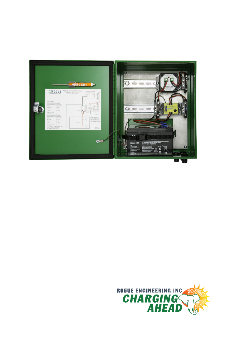
WIRING DIAGRAM AND
INTERIOR PICTORIAL
ROGUE TERRAIN OFF GRID POWER SUPPLY ENCLOSURE 7
Page 8

8 ROGUE TERRAIN OFF GRID POWER SUPPLY ENCLOSURE
 Loading...