


User Manual P1
MC-H
User Manual

Control System
Table of Contents
Safety Information
03
Specication
06
Connection
07
Physical Connection
12
Accessories
Assembly
09
10
13
15
Package
14
Service and Maintenance
User Manual P2

WARNING !
Safety hazard.
Risk of severe
injury or death.
Refer to manual before
installing, powering
or servicing.
Hazardous voltage.
Risk of lethal or
severe electric shock.
Hot surface.
Do not touch.
Fire hazard. Emission hazardous
to eyesight.
This product is for professional use only. It is not for household use.
This product presents risks of severe injury or death due to re hazards, electric shock and falls.
Read this manual before installing, powering or servicing this product, follow the safety precautions
listed below and observe all warnings in this manual and printed on the product.
If you have questions about how to operate the tile safely, please contact your ROE supplier.
PROTECTION FROM ELECTRIC SHOCK
Connect the product to AC mains power within the range 100-240V nominal at 50 or 60 Hz only.
Disconnect the product from power when not in use.
Always ground (earth) the product electrically.
Before using the product, check that all power distribution equipment and cables are in perfect
condition and rated for the current requirements of all connected devices.
Do not use the product if the power cable or a power plug is in any way damaged, defective or
showing signs of overheating.
Do not attempt to open any cover.
Refer any service operation not described in this manual to a qualied technician.
01
Safety Information:
Read the safety precautions in this section before
installing, powering, operating or servicing this product.
The following sysmbols are used to identify important safety information on the product and in this manual:
WARNING! WARNING! WARNING! WARNING! WARNING! WARNING!
User Manual P3

165+5
PROTECTION FROM FIRE
Do not stick lters, masks or other materials directly onto LED modules.
Do not modify the product in any way not described in this manual.
Install only genuine ROE parts in or on the product unless an alternative is described in this manual.
Create an installation by installing tiles at the top and working downwards. Disassemble an installation
by removing tiles at the bottom and working upwards.
Check that all external covers and rigging hardware are securely fastened.
Block access below the work area and work from a stable platform whenever installing, servicing or
moving the product.
Do not operate the product full load if the ambient temperature of power units (Ta) exceeds 50°C (122° F)
or less than -20°C(-4° F).
170+5
1480
2000
Pout/W
Vin/Vac
PROTECTION FROM INJURY
Important warnings
Maximum and minimum ambient temperature:
The maximum ambient temperature for the LED wall is 50 °C; the minimum temperature is (-20°C.)
User Manual P4
High leakage current:
The combination of power boxes in an installation results in increased levels of Leakage current.
In order to avoid risk of electric shock due to high leakage current, proper grounding of the installation
is required.

Data cables:
The data cables provided with this system have special properties for safety. They are not user serviceable.
If the data cables are damaged, replace them only with new ones. Never try to repair a data cable. Per
requirements of the National Electrical Code in the USA, the length of a data cable must not exceed 100 m
(332 feet). Avoid exposure of data cables to accidental contact with lightning or power conductors.
®
MC-H LED tiles cannot be hot swapped:
Always disconnect the power cord from the control box before connecting or disconnecting the cable string
or one of MC-H LED tiles.
Power system
Mains cords:
The power cords delivered with this system have special properties for safety. They are not user Serviceable.
If the power cords are damaged, replace them only with new ones. Never try to repair a power cord.
This equipment MUST be earthed:
In order to protect against risk of electric shock, the installation should be properly grounded. Defeating
the purpose of the grounding type plug will expose you to the risk of electric shock.
User Manual P5

MC-7H Dimensions:
MC-9H Dimensions:
MC-7H Specification:
Specification:
02
User Manual P6
MC-H tiles are lightweight and robust outdoor LED display, installation is very easy. They oer
wide viewing angles with excellent image integrity and color uniformity, owning the common
characteristics of lightweight and rm structure.
LED Conguration
Transparency
Max.Brightness
(Nit or CD/m²)
White SMD 3 in 1
7.5mm
Solid
23.6”×23.6”×3.3”/600.0mm×600.0mm×85.0mm
0.36m²
80×80
17,778
140H/120V degrees
-10° / 0° / +10°
Pixel Pitch
Tile Size(W×H×D)
Tile Area
Pixels/Tile
Pixels/m²
Viewing Angle
9.5kg/20.9lbs
Weight/Tile
Curve Angle
Max. hanging
5,000
(NationStar 2727)
20 tiles
IP(Front/Reverse)
1/5
2000Hz
300W
ETL/TUV/CE
Scan
Gray Scale
Certicates
-20°C to 45°C, 10~90%RHOperating Temp/Humidity
-40°C to 60°C, 10~90%RH
(Unit: mm)
(Unit: mm)
Storage Temp/Humidity
16bit
IP65
Refresh Rate
Max Power/Tile
EvisionProcessor
MC-9H Specification:
LED Conguration
Transparency
Max. Brightness
White SMD 3 in 1
5,500 nits(NationStar 3535)
9.375mm
17%
23.6”×23.6”×3.3”/600.0mm×600.0mm×85.0mm
0.36m²
64×64
11,378
140H/120V degrees
-10° / 0° / +10°
Pixel Pitch
Tile Size(W×H×D)
Tile Area
Pixels/Tile
Pixels/m²
Viewing Angle
8.0kg/17.6lbs
Weight/Tile
Curve Angle
Max. hanging
20 tiles
IP(Front/Reverse)
1/4
3500Hz
320W
ETL/TUV/CE
Scan
Gray Scale
Certicates
-20°C to 45°C, 10~90%RHOperating Temp/Humidity
-40°C to 60°C, 10~90%RHStorage Temp/Humidity
16bit
IP65
Refresh Rate
Max Power/Tile
EvisionProcessor
600
600
600
600
85
85
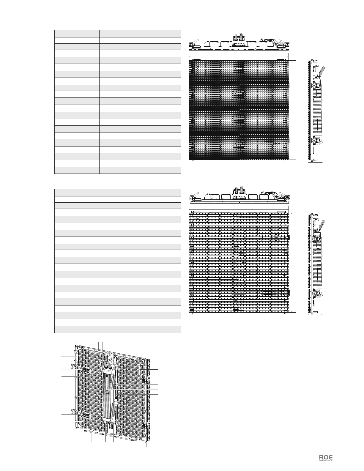
MC-12H Dimensions:
MC-18H Dimensions:
Rear components
User Manual P7
(Unit: mm)
(Unit: mm)
MC-12H Specification:
MC-18H Specification:
LED Conguration
Transparency
Max. Brightness
White SMD 3 in 1
4,800 nits(NationStar 3535)
18.75mm
37%
600.0mm×600.0mm×85.0mm/23.6”×23.6”×3.3”
0.36m²
32×32
2844
140H/120V degrees
-10° / 0° / +10°
Pixel Pitch
Tile Size(W×H×D)
Tile Area
Pixels/Tile
Pixels/m²
Viewing Angle
7.0kg/15.4lbs
Weight/Tile
Curve Angle
Max. hanging
20 tiles
IP(Front/Reverse)
Static
4000Hz
250W
ETL/TUV/CE
Scan
Gray Scale
Certications
-20°C to 45°C, 10~90%RHOperating Temp/Humidity
-40°C to 60°C, 10~90%RH
A. Carry Handle
B. Horizontal Interconnect
connector
C. Control Button
D. Horizontal Interconnect
Dowel
E. Vertical Interconnect
Bolt
F. Vertical Interconnect Hole
G. Up Magnet System
H. Down Magnet System
K. Breather Valve
L. Pothook
M. Power Supply Handle
N. Indicator Light
O. Testing Button
P. Clip
Q. Power In
R. Data In
S. Power Out
T. Data Out
Storage Temp/Humidity
16bit
IP65
Refresh Rate
Max Power/Tile
EvisionProcessor
600
600
85
600
600
85
A
B
E
F H O NS T
M
R
P
G Q
K L
F
E
C
B
C
D
A
D
LED Conguration
Transparency
Max. Brightness
White SMD 3 in 1
6,000 nits(NationStar 3535)
12.5mm
21%
23.6”×23.6”×3.3”/600.0mm×600.0mm×85.0mm
0.36m²
48×48
6400
140H/120V degrees
-10° / 0° / +10°
Pixel Pitch
Tile Size(W×H×D)
Tile Area
Pixels/Tile
Pixels/m²
Viewing Angle
7.5kg/16.5lbs
Weight/Tile
Curve Angle
Max. hanging
20 tiles
IP(Front/Reverse)
Static
4000Hz
320W
ETL/TUV/CE
Scan
Gray Scale
Certications
-20°C to 45°C, 10~90%RHOperating Temp/Humidity
-40°C to 60°C, 10~90%RHStorage Temp/Humidity
16bit
IP65
Refresh Rate
Max Power/Tile
EvisionProcessor

User Manual P8
03
Connection:
MC-H
MC-H
MC-H
MC-H
MC-H
MC-H
AC 220V
Evision
AC 220V
USB
DVI
①
②
MC-H Built in Power Supply
Input Voltage AC 220V
AC 220V AC 220V AC 220V AC 220V AC 220V
③
④④④
⑥
⑥
⑤ ⑤
8 tiles high
MC-H
MC-H
MC-H
MC-H
MC-H
MC-H
AC 220V
Evision
AC 220V
USB
DVI
①
②
MC-H Built in Power Supply
Input Voltage AC 110V
AC 220V AC 220V AC 220V AC 220V AC 220V
③
④④④
4 tiles high
1. Neither Hanging bar nor Vertical Interconnect Bolt can load more than 20 tiles of MC-H.
2. When the Input Voltage is 220V, one Power Cable can load 8 tiles of MC-H; and the Input Voltage is 110V,
one Power Cable can load 4 tiles of MC-H.
Notes:
Data
Power and Data connections of
MC-H tiles
Power
Data Adaptor
⑤
⑤
⑤⑤

Accessories
04
User Manual P9
Name
SAP No.
Dimension
Weight
Evision
201000S0007
W480×H45×D240mm
2.3kg
:
:
:
:
Name
SAP No.
Data Cable
201002S0262
:
:
Dimension
Weight
0.93m
0.2kg
:
:
Name
SAP No.
Dimension
Weight
Max Length
Data Cable
208004S0242
30m
1.4kg
100m
:
:
:
:
:
Name
SAP No.
Dimension
Weight
Max Current
Power Cable
208001S0754/0611
10m/30m
1.8kg/4.6kg
16A
:
:
:
:
:
Name
SAP No.
Dimension
Weight
Material
Hanging Bar
207002S0002
W612×H171×D155mm
3.4kg
Cold Rolled Steel
:
:
:
:
:
Name
SAP No.
Dimension
Weight
Flightcase 12pcs/case
309003-00110
W1135×H903×D692mm
49.0kg
:
:
:
:
Name
SAP No.
Data Adaptor
203000S0015
:
:
Dimension
Weight
W56×H26×D32mm
0.1kg
:
:

User Manual P10
05
Assembly:
Hanging System
Hanging bar Dimensions:
Hanging bar components:
612mm
155mm
171mm
Stacking system assembly exploded diagram
Hanging Installation
Straight Installation
Hanging Clamps
Bolt
Hole
Adjusting Screw
Horizental testing liquid column
Horizontal adjusting knob

User Manual P11
Step 1: Match the holes in straight line.
Step 2: Turn the horizontal adjusting knob and fit securely.
Step 3: Push the bolt in.
Note: Adjust the height of header with the pulley.
Step 1: Match the holes in the angle.
Step 2: Turn the horizontal adjusting knob and fit securely.
1. Fix the Hanging Bar on the Truss
Just turn the Adjusting Screw, to make the Clamps close, the Hanging Bar will be fixed on the Truss safely.
Arc Installation
2. Connect MC-H tiles with the hanging bar
Tiles will be fixed on the hanging bar by Vertical Interconnect Bolt.
Bolt

User Manual P12
06
Physical Connection:
Straight Installation
Horizontal connector operation
1. Press the horizontal red button to loosen the handle.(pic1)
2. Pull the handle to turn the connecting bar.(pic2)
3. Connect two tiles and align them.(pic3)
4. Push handle back for locking.(pic4)
Picture 1 Picture 2 Picture 3 Picture 4 Picture 5
Vercal connector operaon
2. Tiles will be attached together by magnets automatically.(pic3)
3. Lock(pic4)
Connector Convex 10 degrees Concave 10 degrees
1. Open Bolt rstly.(pic2)
Picture 1 Picture 2 Picture 3 Picture 4
Curve Installation

The control system of MC-H series consist of receiving card and sending card.
Receiving card is integrated with LED tiles.
Control System:
07
User Manual P13
Software:
Please read software manual rstly, (download link as below): Http://www.roevisual.com/how-to-make-led-display.
Evision (201000S0007)
Working
v o
ltage
Power
100-240V AC
<20W
Working temperature
-20°C to 45°C
Input port DVI
Output ports number 4 ports
Communication port USB/RJ45
1920×1080 60Hz
Max.Resolution(Input)
Data transmission port Gigabit Ethernet
Material AL6061
Dimension W480×H45×D240mm
Weight 2.30kg
1. Power switch
2. Number keys
3. LCD screen
4. Function keys
5. Knob
0 1 2 3 4
5 6 7 8 9
Black
DVI
HDMI
OK
Esc Fn
Menu
Front
Behind
INPUT 100-240V AC 50/60HZ
PORT 4PORT 3PORT 2PORT 1USB2USB1HDMIDVI
1
6
7
8
9
10
2 3 4 5
Specifications
6. DVI port
7. HDMI port
8. USB port
9. RJ45 data port
10. Power port
Diagram:

Service and Maintenance:
08
User Manual P14
Figure 1: Maintenance on overall installation Figure 2: Replacement of LED strips
1. Loosen screws and replace the faulty strips.
2. Do repair for the faulty strips.
MC-9H
MC-12H
MC-12H
MC-18H
MC-18H
MC-12H
MC-12H
MC-18H
MC-18H
MC-18H
MC-18H
MC-18H
MC-18H
MC-18H
MC-18H
MC-12H
MC-12H
MC-12H
MC-12H
MC-12H
MC-12H
MC-9H
MC-9H
MC-7H
MC-7H
MC-7H
MC-7H
MC-9H
MC-7H
MC-9H
Note: When the failure occurs, the color of indicator light will show the prority in the following order.
1. Error receiving card.
2. DC output above 5V or below 4.3V
3. Excessive tile temperature.
4. Wrong signal.
5. No signal.
Light status on the rear of MC-H Series
OK
OK
OK
OK OK
Wrong signal
No signal
OK
OK
OK
Signal input from top
to bottom
Normal
Normal
The receiving card doesn’t work.
DC output above 5V or below 4.3V
The temperature of tile exceeds 50°C.
Disconnected the UTP cable between the receiving card
and the tile.
1. The bad connection between the receiving cards.
2.The pins on the receiving card is curved or broken.
Signal input from bottom
to top
Green
Green
(2Hz/second)
(2Hz/second)
(2Hz/second)
(2Hz/second)
(Always)
(Always)
(Always)
Blue
Blue
Red
Red
Yellow
Error receiving card
The power supply DC-DC abnormal
Power Data Color of Light Factors

Package
09
User Manual P15
8 pcs LED tiles per flightcase
Flightcase
1,112.0
196.0 720.0
146.0
820.0
1,112.0
600.0
80.0
903.0
570.0
509.0
669.0
625.0
1,134.6
691.6
150.0
505.0
100.0 100.0
100.0
100.0
100.0
100.0
100.0
100.0
100.0
60.0
669.0
21.00
9li wood
6mmEVA
21.00
300.0
200.0
390.0
175.00
103.00
90.00
25.00
310.0
50.0
470.0
44.0
80.00
56.0
56.0
56.0
44.0
120.00
60.0

User Manual P16
ROE Visual Co., LtdROE Visual Europe B.V ROE Visual US, Inc
www.roevisual.com www.roevisual.comwww.roevisual.com
Bldg 7, Zhong Yuntai Industrial Park,
Shiyan Town, Shenzhen, China.
E: roe@roevisual.com
T: +86-755-8392 4892
F: +86-755-8392 4891
Zernikelaan 2a,
9351VA Leek, The Netherlands.
E: europe@roevisual.com
T: +31 (0)50 211 0990
2514 N Naomi Street,
Burbank, CA, 91504.
E: usa@roevisual.com
T: +1 747 229 9190
 Loading...