

User Manual P1
Carbon
User Manual

Service and Maintenance
Table of Contents
Safety Information
03
Specication
06
Connection
07
Control System
21
Accessories
Installation
09
10
22
23
Package
User Manual P2
WARNING !
Safety hazard.
Risk of severe
injury or death.
Refer to manual before
installing, powering
or servicing.
Hazardous voltage.
Risk of lethal or
severe electric shock.
Hot surface.
Do not touch.
Fire hazard. Emission hazardous
to eyesight.
This product is for professional use only. It is not for household use.
This product presents risks of severe injury or death due to re hazards, electric shock and falls.
Read this manual before installing, powering or servicing this product, follow the safety precautions
listed below and observe all warnings in this manual and printed on the product.
If you have questions about how to operate the tile safely, please contact your ROE supplier.
PROTECTION FROM ELECTRIC SHOCK
Connect the product to AC mains power within the range 100-240V nominal at 50 or 60 Hz only.
Disconnect the product from power when not in use.
Always ground (earth) the product electrically.
Before using the product, check that all power distribution equipment and cables are in perfect
condition and rated for the current requirements of all connected devices.
Do not use the product if the power cable or a power plug is in any way damaged, defective or
showing signs of overheating.
Do not attempt to open any cover.
Refer any service operation not described in this manual to a qualied technician.
01
Safety Information:
Read the safety precautions in this section before
installing, powering, operating or servicing this product.
The following sysmbols are used to identify important safety information on the product and in this manual:
WARNING! WARNING! WARNING! WARNING! WARNING! WARNING!
User Manual P3
165+5
PROTECTION FROM FIRE
Do not stick lters, masks or other materials directly onto LED modules.
Do not modify the product in any way not described in this manual.
Install only genuine ROE parts in or on the product unless an alternative is described in this manual.
Create an installation by installing tiles at the top and working downwards. Disassemble an installation
by removing tiles at the bottom and working upwards.
Check that all external covers and rigging hardware are securely fastened.
Block access below the work area and work from a stable platform whenever installing, servicing or
moving the product.
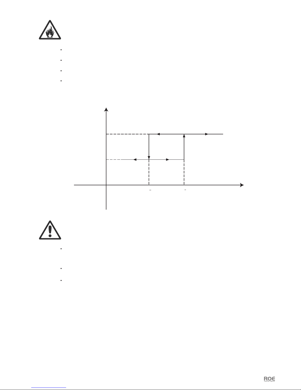
Do not operate the product full load if the ambient temperature of power units (Ta) exceeds 45°C
(113° F) or less than -20°C(-4° F).
170+5
1480
2000
Pout/W
Vin/Vac
PROTECTION FROM INJURY
Important warnings
Maximum and minimum ambient temperature:
The maximum ambient temperature for the LED wall is 45 °C; the minimum temperature is (-20°C.)
User Manual P4
High leakage current:
The combination of power boxes in an installation results in increased levels of Leakage current.
In order to avoid risk of electric shock due to high leakage current, proper grounding of the installation
is required.
Data cables:
The data cables provided with this system have special properties for safety. They are not user serviceable.
If the data cables are damaged, replace them only with new ones. Never try to repair a data cable. Per
requirements of the National Electrical Code in the USA, the length of a data cable must not exceed 100 m
(332 feet). Avoid exposure of data cables to accidental contact with lightning or power conductors.
®
Carbon LED tiles cannot be hot swapped:
Always disconnect the power cord from the control box before connecting or disconnecting the cable string
or one of Carbon tiles.
Power system
Mains cords:
The power cords delivered with this system have special properties for safety. They are not user Serviceable.
If the power cords are damaged, replace them only with new ones. Never try to repair a power cord.
This equipment MUST be earthed:
In order to protect against risk of electric shock, the installation should be properly grounded. Defeating
the purpose of the grounding type plug will expose you to the risk of electric shock.
User Manual P5
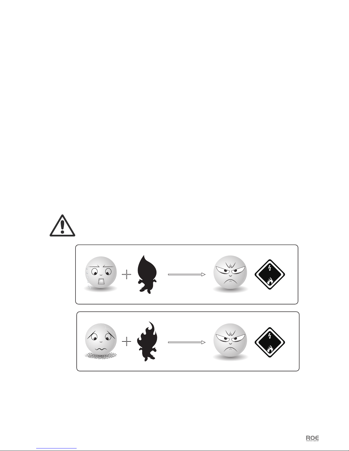
FRAME PROTECTION
Water>150°C
FirePowder
Danger
Danger
Note: At normal temperature environment, Magnesium alloy is abosolutely stable and safe.
It’s dangerous only in:
1. Temperature higher than 150°C with water;
2. Powder with re.
Mg
Mg
Mg
Mg
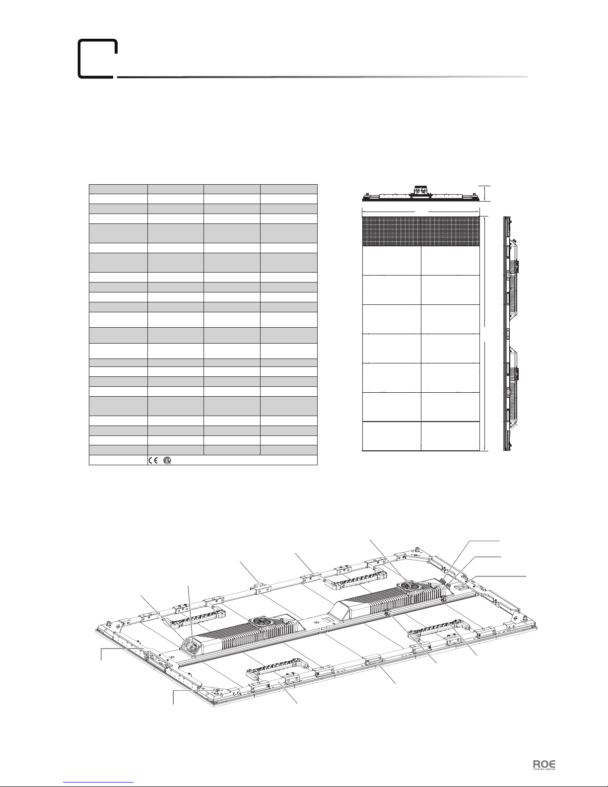
600.0mm
1200.0mm
77.0mm
Carbon-5 Dimensions:
Carbon Specication:
Diagram:
Specification:
02
User Manual P6
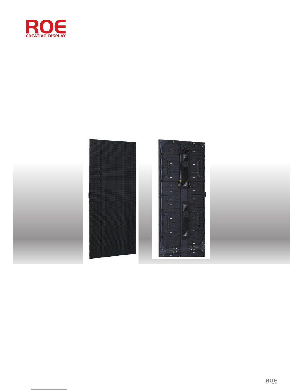
Carbon panels are our rst line incorporating lightweight carbon ber technology. More and more uses are being
found for versatile, ultra-lightweight panels from the stage to the corporate event, and Carbon panels strike the
perfect balance of stability and weight. All this whilst preserving the easy setup and maintenance of all ROE
product to save on time and labor costs.
Power Out
Data Out
Carry Handle
Carbon Fibre Tube
Fixed Block
Clip
Side Lock
Fixed Block
Cooling Fan
Dowel Pin
Magnet
Data In
Power In
Testing Button
Pixel Pitch
LED Conguration
Viewing Angle(Hor/Vert)
Max. Brightness
Transparency
Pixel Density
Pixel / Tile
Refresh Rate
Gray Scale
Scan
Frame Material
Tile Weight/Tile
Tile Dimension(W×H×D)
Carbon
Carbon Fiber + Magnesium
Alloy
5.77mm
HB Black SMD 3-in-1
White SMD 3-in-1
140°/110°
4,500nits(Multicolor 2727)
6,000nits(NationStar 1921)
Solid
30,044/sqm
104×208
3,840Hz
16bit
13.9kg
1/4
600mm×1,200mm×77mm
23.6”×47.2”×3.0”
CB5CB3
Curve(optional)
Concave Max. 15°
Convex Max. 10°
600mm×1,200mm×72mm
23.6”×47.2”×2.8”
Carbon Fiber + Magnesium
Alloy
8.33mm
White SMD 3-in-1
140°/110°
5,000nits(NationStar 2727)
Solid
14,400/sqm
72×144
2,880Hz
16bit
12.7kg
Concave Max. 15°
Convex Max. 10°
1/6
CB8
Carbon Fiber + Magnesium
Alloy
3.75mm
Black SMD 3-in-1
140°/140°
1,500nits(NationStar 2121)
Solid
71,111/sqm
160×320
1,920Hz
16bit
13.2kg
1/16
600mm×1,200mm×77mm
23.6”×47.2”×3.0”
Concave Max. 15°
Convex Max. 10°
IP Rating(Front/Rear)
Max Power/Tile
Lifetime
Operating Temp/Humidity
Processor Brompton Brompton Brompton
Storage Temp/Humidity
Max. Hanging*
IP65
650W
500W
≥50,000h
-20°C to 45°C, 10~90%RH
-40°C to 60°C, 10~90%RH
12 tiles
Max. Stacking 4 tiles
IP65
320W
≥50,000h
-20°C to 45°C, 10~90%RH
-40°C to 60°C, 10~90%RH
12 tiles
4 tiles
IP43
540W
≥50,000h
-20°C to 45°C, 10~90%RH
-40°C to 60°C, 10~90%RH
12 tiles
4 tiles
Certications
*Notes: The single hanging bar is able to support up to 12 tiles when the safety factor is 5.
03
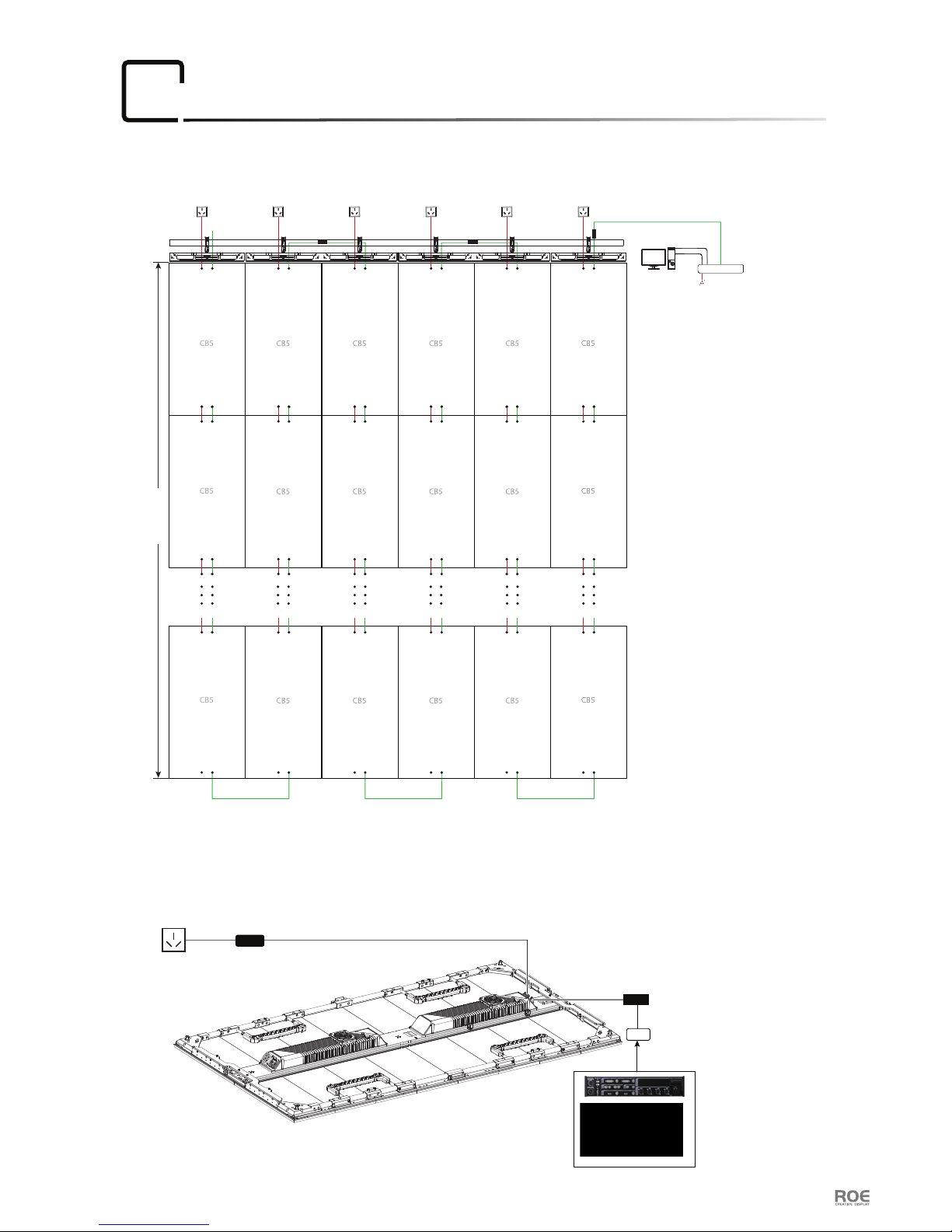
Connection
User Manual P7
Processor
AC 220V
CAT-5
DVI
①
②
Carbon 5 Built in Power Supply
Input Voltage AC 220V
Hanging System
1. Neither Hanging Bar nor Vertical Connector can load more than 20 tiles of Carbon 5.
2. When the Input Voltage is 220V, one Power Cable can load 4 tiles of Carbon 5; and the Input Voltage is 110V,
one Power Cable can load 2 tiles of Carbon 5.
Notes:
AC 220V AC 220V AC 220V AC 220V AC 220V AC 220V
③
④
⑤ ⑤
⑤
⑥
4 tiles high
CB5
CB5
CB5
CB5
CB5
CB5
Power and Data connections of Carbon tiles
Data
WeiPu
Brompton
Power
Data Adaptpr

User Manual P8
Processor
AC 220V
CAT-5
DVI
①
②
Carbon 8 Built in Power Supply
Input Voltage AC 220V
Hanging System
1. Neither Hanging Bar nor Vertical Connector can load more than 20 tiles of Carbon 8.
2. When the Input Voltage is 220V, one Power Cable can load 8 tiles of Carbon 8; and the Input Voltage is 110V,
one Power Cable can load 4 tiles of Carbon 8.
Notes:
AC 220V AC 220V AC 220V AC 220V AC 220V AC 220V
③
④
⑤ ⑤
⑤
⑥
8 tiles high
CB8
CB8
CB8
CB8
CB8
CB8
Power and Data connections of Carbon tiles
Data
WeiPu
Brompton
Power
Data Adaptpr
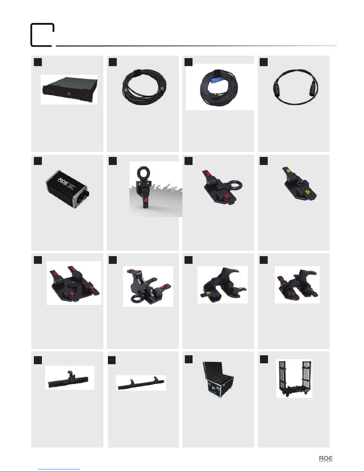
Accessories
04
User Manual P9
Name
SAP No.
Dimension
Weight
Brompton
311003-00010
W508×H432×D89mm
12.0kg
:
:
:
:
Name
SAP No.
Dimension
Weight
Data Cable
208004S0242
30m
1.4kg
:
:
:
:
Name
SAP No.
Dimension
Weight
Max Capacity
Power Cable
208001S0754/0611
10/30m
1.8kg/4.6kg
16A
:
:
:
:
:
Name
SAP No.
Dimension
Weight
Data Cable
208002S0262
0.93m
0.2kg
:
:
:
:
Name
SAP No.
Dimension
Weight
Data Adaptor
203000S0015
W56×H32×D26mm
0.1kg
:
:
:
:
① ② ③ ④
⑤
Name
SAP No.
Dimension
Weight
Max.Capacity
Flightcase
30900300330
W1300×H840×D800mm
80kg
7 tiles of CB
:
:
:
:
Name
SAP No.
Dimension
Weight
Max.Capacity
Dolly
206002C0277
W1310×H1605×D790mm
102kg
12 tiles of CB
:
:
:
:
:
Name
SAP No.
Dimension
Weight
Hanging Bar
207002S0096
W589×H188×D157mm
3kg
:
:
:
:
Name
SAP No.
Dimension
Weight
Hanging Bar
207002S0097
W1189×H188×D157mm
6.1kg
:
:
:
:
⑥
⑥
⑥
Name
SAP No.
Dimension
Weight
Material
Hanging Connection Plate
206002S0384
W142×H82×D25mm
232g
ADC12/SUS304
:
:
:
:
:
Name
SAP No.
Dimension
Weight
Material
Connection Plate
304012001080
W142×H45×D25mm
125g
SUS304
:
:
:
:
:
Name
SAP No.
Dimension
Weight
Material
Hanging Connection Plate
206002S0638
W110×H38×D25mm
232g
ADC12/SUS304
:
:
:
:
:
Name
SAP No.
Dimension
Weight
Material
Connection Plate
30401201079
W142×H90×D25mm
240g
SUS304
:
:
:
:
:
Name
SAP No.
Dimension
Weight
Material
Hanging Curve
Connection Plate
206002S0468
W142×H118×D85mm
390g
ADC12/SUS304
:
:
:
:
:
Name
SAP No.
Dimension
Weight
Material
Curve Connection Plate
30401201044
W152×H72×D85mm
288g
SUS304
:
:
:
:
:
Name
SAP No.
Dimension
Weight
Material
Curve Connection Plate
30401201043
W142×H109×D85mm
376g
SUS304
:
:
:
:
:

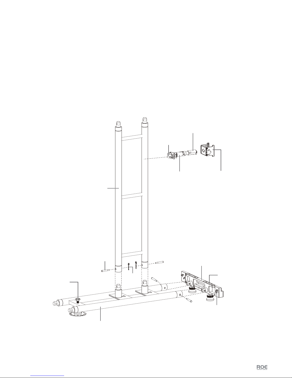
User Manual P10
Installation:
05
Hanging System
Hanging Bar Diagram:
0.6m Hanging Bar Dimensions:
1.2m Hanging Bar
Optional
Eyebolt
Adjusting Screw
Adjusting Knob
Hanging Clamps
Fixed Seat
Dowel Pin
Magnet Component
589mm
1189mm
188mm
157mm

User Manual P11
Flat Installation
Just turn the Adjusting Screw, to make the Clamps close, the Hanging Bar will be xed on the
Truss safely.
1. Fix the Hanging Bar on the Truss
Tiles will be attached to the Hanging Bar by Magnets automatically.
Notes: (For Safety) Please do this by two persons.
2. Connect Carbon tiles with the Hanging Bar
connection plate diagram:
Control Button
Handle
Connection Plate
Bolt Hole for celling
(
Round screw M10×10mm)
3. Fix Carbon tiles on Hanging Bar by Connection Plate
Locating Hole Position Pin

User Manual P12
Two kinds of Connection plate.
two handles: four handles:
Press the red button to loosen the handle, align the locating hole and dowel pin, push handle back for locking.
1
2
3. Use Connection Plate with eyebolt for hanging also.
Case 1
Locating
Hole
Case 2

User Manual P13
5. Flat Installation Components
Major components of at installation assembly are:
0.6m Hanging Bar × 2 1.2m Hanging Bar × 2 Connection Plate × 19 CB tiles × 12
4. Interconnect Side Lock

For the Magnet components,
in vertical connection at the
edge of CB tiles, must use
Connection Plate .
User Manual P14
Curve Installation
Hanging bar and Connection Plate indicate
The connecting angle of curve connection plates can be adjustable with any size (Max.concave 15°,
Max.convex 10°).
concave 15°
(four handles)
convex 10°
(four handles)
1
1
2
2
at
(two handles)
at
(two handles)
3
4
4
4
4
concave 15°
(two handles)
convex 10°
(two handles)
5
6
5
6

User Manual P15
Hanging Connection Plate
145
concave 15°
Sliding Plate
Eyebolt
Degree Handle
Handle
Control
Button
7
7
at
8
convex 10°
9
9
Connection Plate
or
2 6
or
or
Nothing
User Manual P16
Stacking System
Stacking system assembly exploded diagram.
Stacking System Support Components
Major components of the Stacking System support assembly are:
1. Base Bar
2. Base Truss
3. Rear Support Truss
4. Rear Bridge(Half Coupler, Brace Arm, Stacking Connector, Clamp Adaptor)
Base Bar
Base Truss
Adjusting Knob
Rear Support Truss
Stacking Connector
Half Coupler
Pin
Safely Clip
Position Pin
Magnet Component
Brace Arm Clamp Adaptor
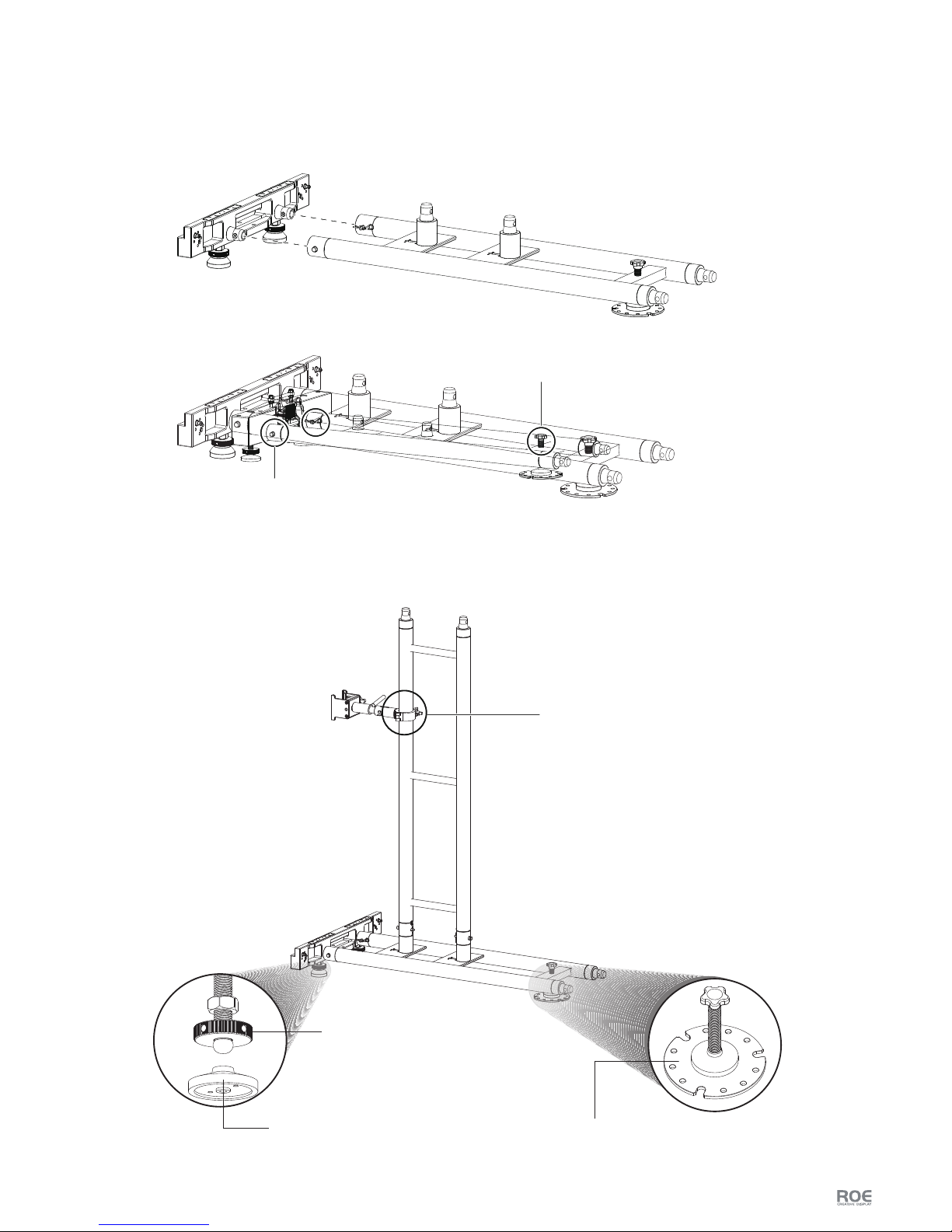
User Manual P17
Stacking Installation
1. Base Bar connection with Base Truss
Connect the Base Bar and Base Truss by Pin and Safely Clip.
2. Rear Support Truss and Rear Bridge installation
Lock of Base Truss
Adjust the Knob and make sure the Base Truss
and Base Bar in same horizontal
Half Coupler and Screw
Knob
(Adjusting height)
Universal Adjusting Footpad
(Keep the Base Bar always horizontal )
Plate
(Fix the Base Truss on the ground )
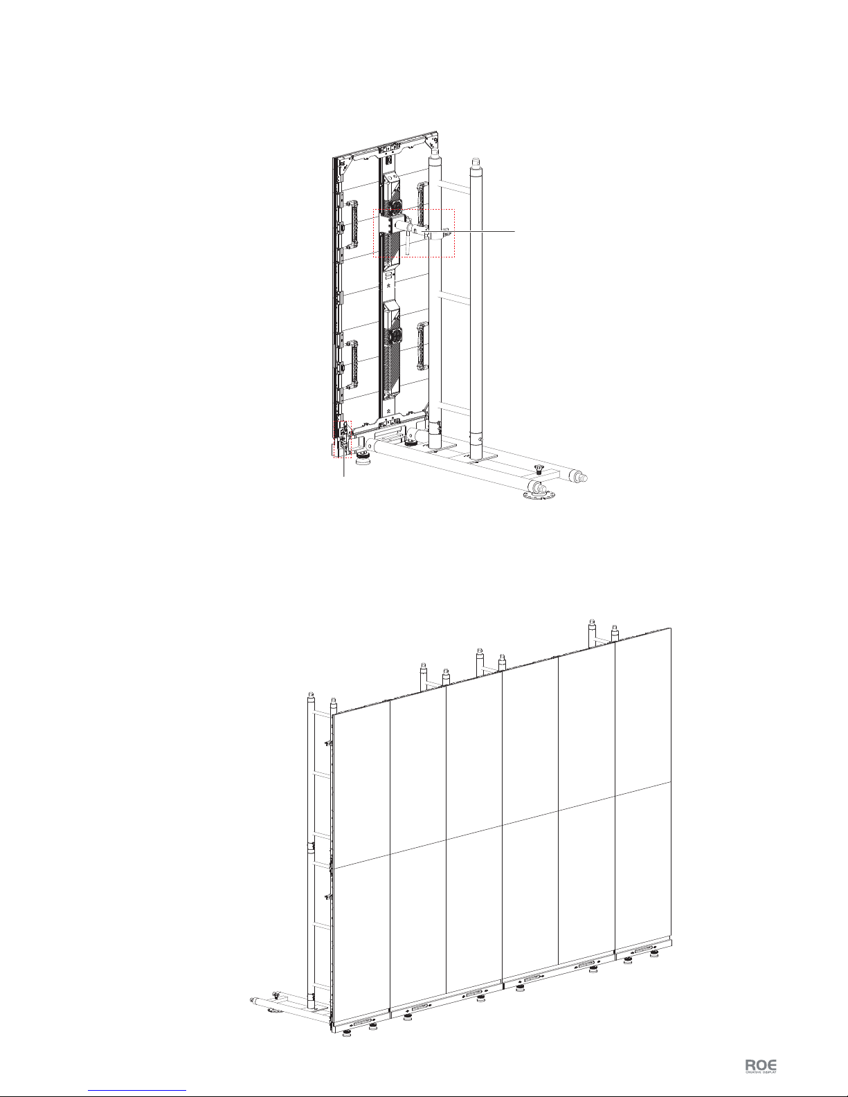
User Manual P18
3. Tiles Installation
Connect the tiles and Base Bar by Vertical Connector, and Rear Support Truss by Rear bridge.
4. Stacking Installation
Tile(2×6)Accessories Count:
Base Bar: 2×0.6m, 1×1.2m
Base Truss: 4
Rear Support Truss: 8
Rear Bridge: 8
Connection Plate: 19
Vertical Connector
Rear Bridge
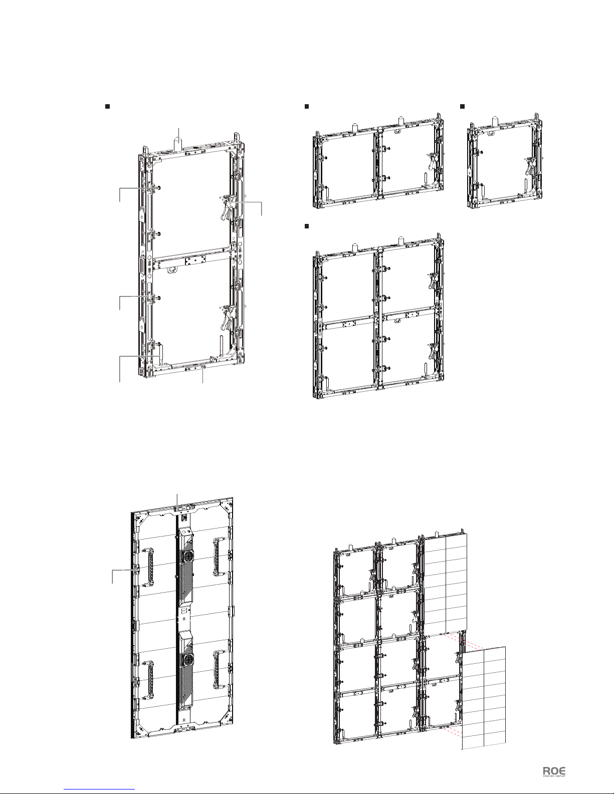
User Manual P19
Mounting System
Diagram: Touring Frame - T4
T4V T4H T4M
T4S
Diagram: CB tiles Connect CB tiles with T4 Touring Frame
Keep the lock pin of T4 Open.
Alignment the position pin of T4 and locating hole of
CB, it will be attached to T4 by Magnets automatically.
Then loosen the lock pin for locking.
Lock Pin
Magnet
Position Pin
Locating Hole
Iron Plate
②
①
③
Vertical Interconnect Latch Lever
Horizontal
Interconnect Lock
Vertical King Pin
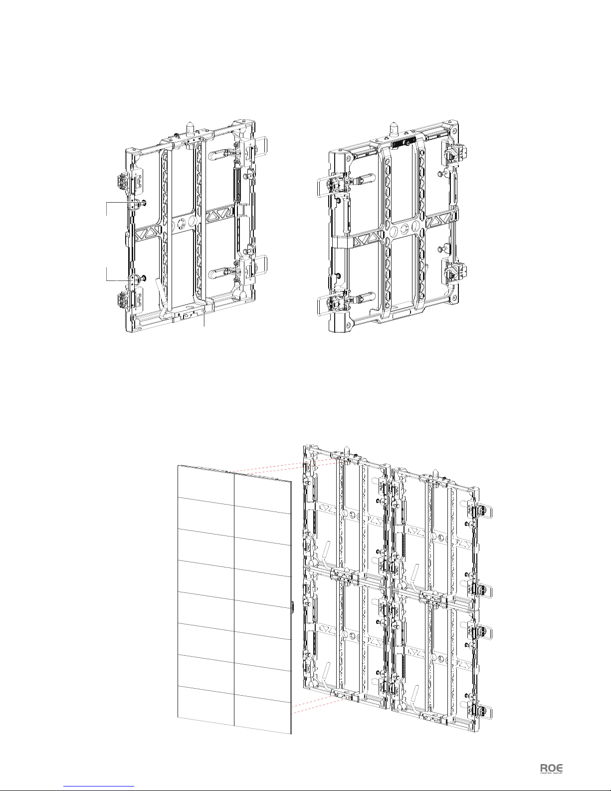
User Manual P20
Diagram: Touring Frame - T2
Magnet
Position Pin
Connect CB tiles with T2 Touring Frame
Keep the lock pin of T2 Open.
Alignment the position pin of T2 and locating hole of CB, it will be attached to T2 by Magnets automatically.
Then loosen the lock pin for locking.
②
①
③
Lock Pin

SMART / REALTIME / SOPHISTICATED COLOUR MANAGEMENT / REMOTE
Brompton(311003-00010)
Control System:
07
Software
Please read software manual firstly, (download link as below): Http://www.roevisual.com/how-to-make-led-display.
Electrical
Input ports
Output ports
Max. capacity
Canvas size
Remote control
Dimensions
Weight
Certification
2 × SD/HD/3G-SDI, DVI-I, Bi-/Tri-level Reference Sync
4 × Tessera Protocol (Neutrik Ethercon)
2 Million Pixels (60Hz 24bit)
Internal processing
quality
12bits per colour
1920 × 1080 pixels
9.0kg/20.0lbs
CE, ETL/cETL
Support for control via eDMX (ArtNet) and DMX512
(on XLR 5-pin)
508mm × 89mm × 432mm
20” × 3.5” × 19”
100 - 240V AC, 47Hz - 60Hz, 1- 0.5A
Autoranging power supply.
User Manual P21
Specications
Rear Panel Connections
All specifications are believed to be correct at time of writing.
Specifications are not guaranteed to be free from errors, and are subject to change at any time.
DisplayPort Input
Remote Control DVI Input
Local UI
IEC Mains InputGigabit Ethernet Outputs
3G-SDI Input
DMX 512-A Input
On/Off Switch
Loop Thru Ports
Reference Inputs
Service and Maintenance:
08
User Manual P22
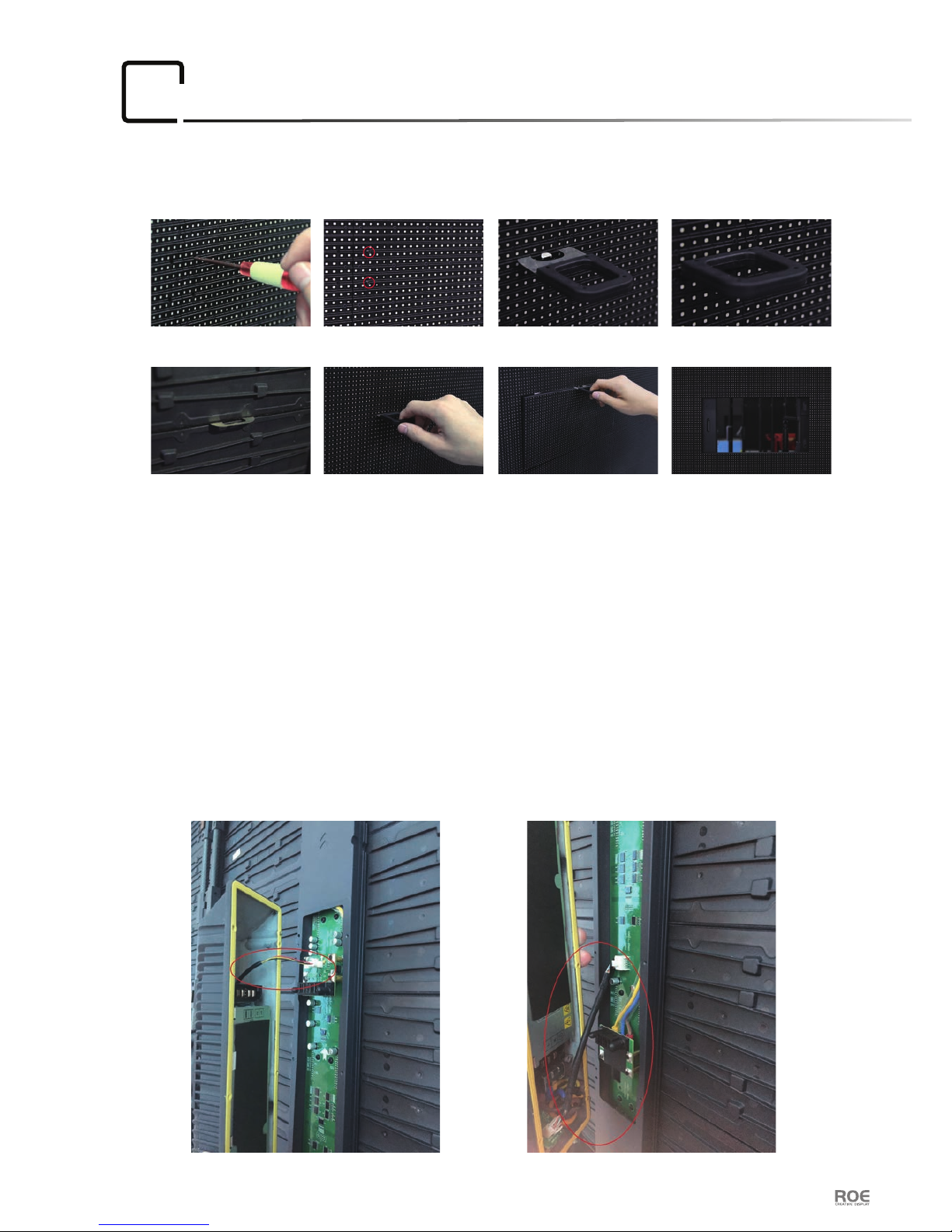
2. Notice the data cable and power cable connected to the HUB board in the spine when
replacing the spin. Don’t be forced to remove the spine in case of dragging out
the cables and broken the connectors.
Maintenance:
Picture 1 Picture 2 Picture 3 Picture 4
Picture 5 Picture 6 Picture 7 Picture 8
1. Loosen the screw(a total of six screws) on the front of the module.
2. The loosened screws can be remained on the tile.
3. Insert the tool into the gap on the top of the module that you want to take out.
4. Make sure that the iron piece at the front of the tool is fully inserted in the gap.
5. You can check it at the back.
6. Pull the handle.
7. The module comes out, be caution that the module falls o.
8. Take the module out from the tile.
1. Maintenance on overall installation, just replace the bad module.
(twist force: 1.8kg f-cm)
.
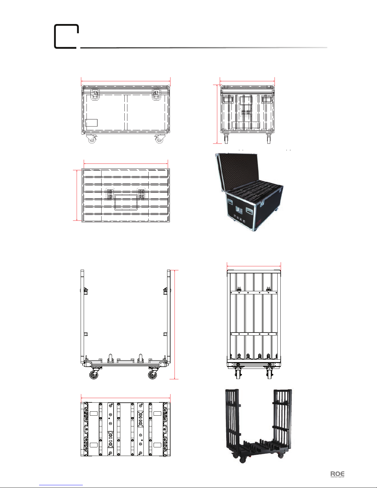
Package
09
7 pcs LED tiles per Flightcase
12 pcs LED tiles per Dolly
User Manual P23
1300mm
1210mm
800mm
840mm
774mm
1310mm
1605mm
790mm

User Manual P24
ROE Visual Co., LtdROE Visual Europe B.V ROE Visual US, Inc
www.roevisual.com www.roevisual.comwww.roevisual.com
Bldg 7, Zhong Yuntai Industrial Park,
Shiyan Town, Shenzhen, China.
E: roe@roevisual.com
T: +86-755-8392 4892
F: +86-755-8392 4891
Zernikelaan 2a,
9351VA Leek, The Netherlands.
E: europe@roevisual.com
T: +31 (0) 50 211 0990
2514 N Naomi Street,
Burbank, CA, 91504.
E: usa@roevisual.com
T: +1 747 229 9190
 Loading...