

Page 1
33
RODIX INCORPORATED
TOLL FREE (800) 562-1868, FAX (815) 316-4701
E-mail [email protected]
FEEDER CUBE ®
VF-3-OR, P/N 121-000-0772* and 121-200-0772
* Includes CFR vibration sensor P/N 123-215
OIL RESISTANT MODEL
IMPORTANT: APPLICATION NOTE
Input: 85 - 264 VAC, 50/60 HZ.
Single Unit Fuse Size: 5 AMPS
Output: 0 - 120/240 VAC
Maximum output voltage matches input voltage
Output Frequency: 5 - 300Hz
Rated Output Current: 3 Amps at 120V or 1.5 Amps at 240V
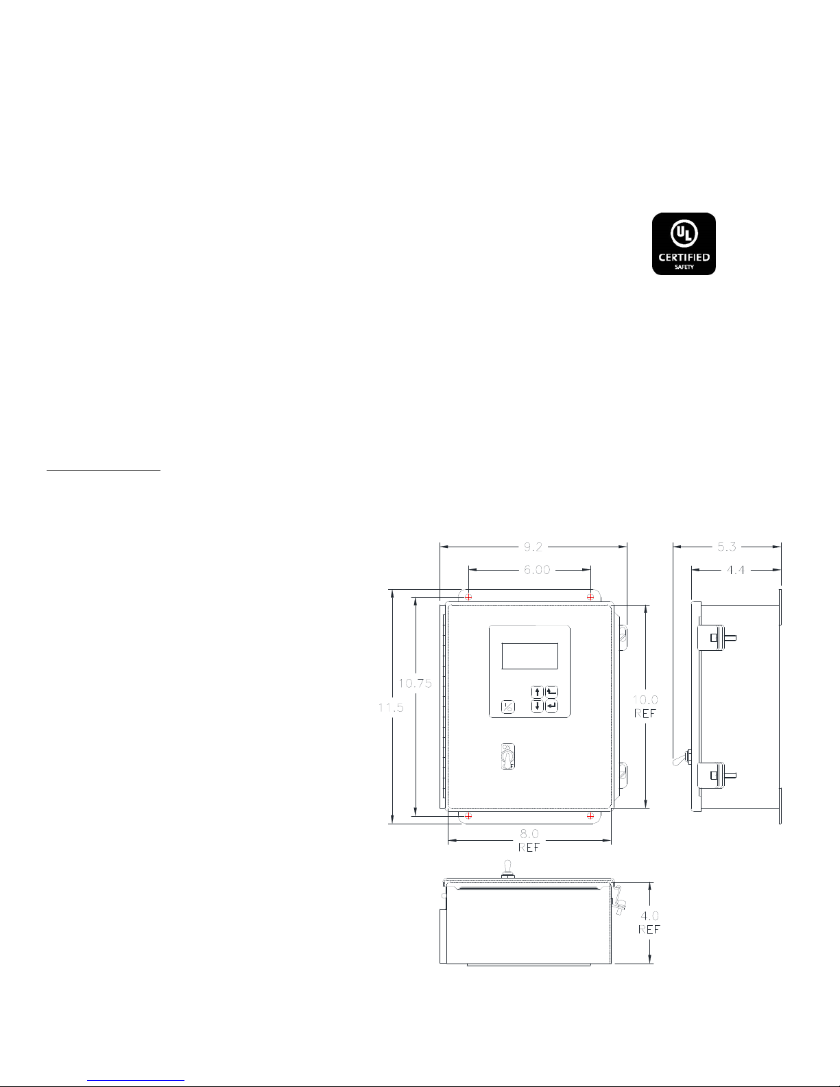
Rated for IP54 environment
UL rated for Type 5 environment
Model Information: The Autotune Series of Variable Frequency Feeder Cubes® gene rates an output frequency for fe eding
that is independent from the power line frequency. An optional vibration sensor, P/N 123-215, can be used to maintain the
vibratory feeder at a constant feed rate. The start/stop operation of the output can be controlled with an optional parts
sensor. For more information on this control, refer to the enclosed Adjustments and Set Up pages.
© 2005, 2017 RODIX INC. 5/4/2017 Page 1
rodix.com
File No. E1832
Page 2
CONNECT SINK OR SOURCE WIRE TO "SIG" INPUT
SE N SOR OPTION
S
O-
BOWL/HOPPER
S
-
Bl #14
4-20mA
-
Bl #14
1
E 4
+
Bu
LCD Display TB3
13 9 5
INPUT POWER
85 - 264 VAC
SENSO R
+
Bl #1 4
L2
Bl #14
TB1
14
F2
0-10 VDC
BANNER
Bl #1 4
Enable
JUMPER
SIG
Chassis
4
E
Load
Out
S
+
Line
Input
Aux Out
-
Bu
+
Bl #14
P1
R21
12 8
INTERLOCK OUTPUT
S
CF R Sensor
P/N 123-215
OUTPUT
TB4
Chassis
P/N 111-500
Analog
Bl #1 4
Out -
LCD Contr a st
+
Br
Bl #1 4
Out +
Danger!
Shock
Hazard
E
ACCEPTS BOTH OPTIC AND PROX SENSORS, NPN OR P NP.
+
Analog Gnd .
11 7
MASTE R CON TROL
SM312FP1H
OPTICS
INPUT
3
Bl
OPTIC SENSOR
1
-
RUN
2
R27
High Voltage LED
L1 O+
Tighten Main Terminals
to 9 in. lbs.
+
Accel.
L1
TB2
1
F1
-
Br
Gr/Yl #14
Keypad
2
-
+
1
L2 10 6 3
3 1
TB2
-
12VDC, <1 WATT
1N4006 DIODE
-
SIG
AIR VALVE
Air-Valve Connections
Fi
g
ure 2
+
+
Aux Out
2
RODIX, INC.
Toll Free (800) 562-1868, FAX (815) 316-4701
Email [email protected]
rodix.com
VF-3-OR cover.docx 6/2/2017 Page 2
RODIX INC.
FEEDER CUBE
VF Series
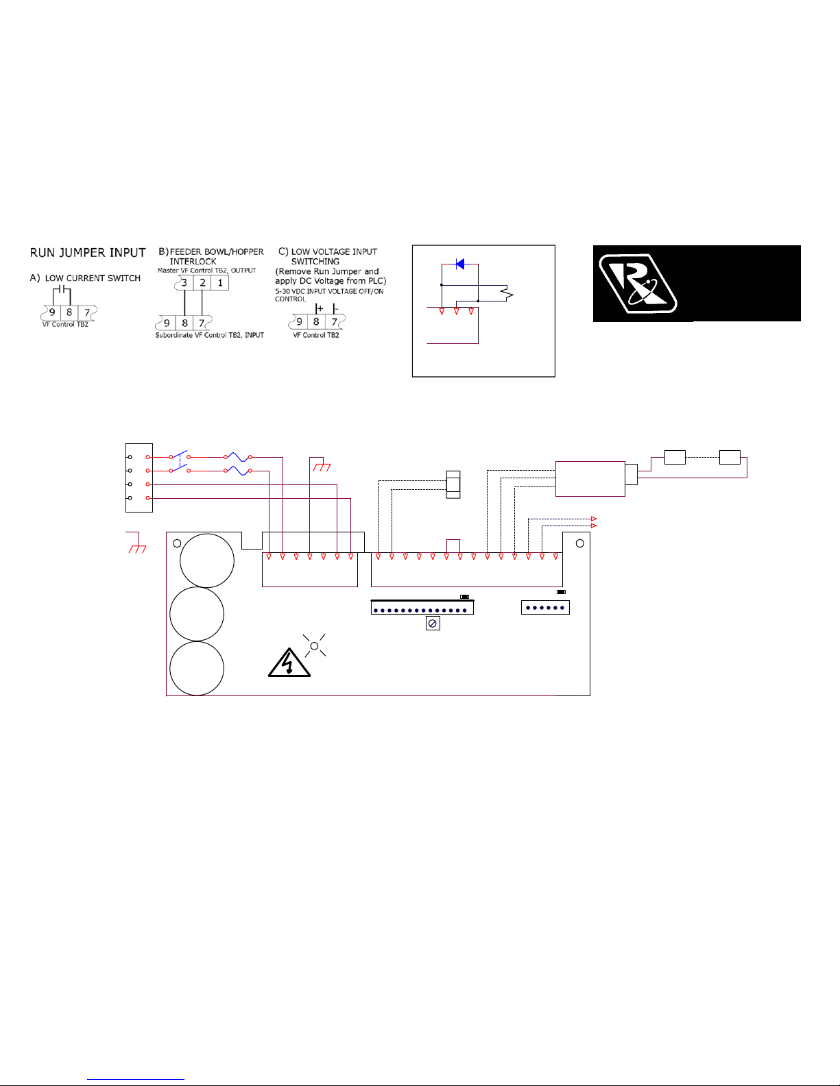
WIRING DIAGRAM
Figure 1
Page 3
Auto Tune Series of
Variable Frequency controls
General Description
The Auto Tune Series of variable frequency feeder
controls are ideal for vibratory bowls, storage
hoppers and linear inline feeders. The VF Series
output frequency can be adjusted to match the
natural frequency of the vibratory feeder. The
amplitude sets the amount of vibration. The CFR
vibration sensor allows the control to Auto Tune
to
the optimum feeding frequency. The CFR sensor
also regulates the vibration level. A feeder operating
at its resonant frequency will perform efficiently using
less power and provide better feeding performance.
Standard features include an easy to read backlit
display, easy to understand status messages and
simple to navigate set-up menu. Resonant
frequency can be found manually using the keypad
or automatically by mounting the optional vibration
sensor, P/N 123-215, letting the controller scan the
frequency range. The vibration sensor also provides
feedback to help maintain a constant parts feed rate.
Other features include a parts sensor input, an
interlock output, enable input, soft-start adjustment,
line voltage compensation, 4-20mA amplitude
control, and lockable menu.
Control Sizing
A VF control should be sized according to the
amperage needed to operate a full vibratory feeder.
If the amps is unknown, use the following guidelines.
Most hoppers and linear inline feeders can be
powered by a VF-3 control. Typical two coil feeder
bowls can be driven by a VF-9 control. Two coil
bowls with outside tooling that require a high feed
rate should be connected to a VF-12 control. Three
coil bowls should use a VF-12 control. Four coil
bowls should use a VF-18 control.
© 2005, 2017 RODIX INC.
Mounting
The VF-3, VF-9 and VF-18 controls may be mounted
vertically or horizontally, but the VF-3 and VF-9
controls stay cooler when mounted vertically. Mount
the control to a metal plate or mount it so that the
back of the heat sink is fully exposed to the air.
Important: The heat sink fins of the VF-12 power
control must be mounted vertically with three
inches of space above and below the heat sink
for proper cooling.
The VF-18 control and heat sink are cooled by a fan.
Mount the heat sink of the VF-18 control flat against
a metal plate in order to ensure the fan’s air flow
through the heat sink.
Electrical Connections
Make the electrical connections prior to turning the
control on. Once connections are made, any desired
changes to the software settings can be made with
the cover closed. Warning: Shock Hazard! Do not
operate control with cover open.
Safety codes require single phase 120 or 240 VAC
installations to bypass the phase 2 fuse, L2. To
bypass, remove the wire connecting TB1-L2 to the L2
fuse holder. Remove the terminal end of the wire
connecting the L2 fuse to the power switch and
connect it to TB1-L2.
1. Parts Sensor Input
(Photo-sensor or Proximity Switch)
Connect a three wire, current-sourcing (PNP) or
current-sinking (NPN) sensor to TB2 as shown on the
enclosed wiring diagram. The sensor must be able
to operate on 12VDC and be capable of switching at
least 3.0 mA. See Parts Sensor Settings section for
more operation information.
2. Run Input Enable
A Run Jumper comes installed from the factory as
shown on the enclosed wiring diagram.
If the run input is to be controlled by a relay contact,
switch, or other device, replace the factory-installed
jumper (see TB2 of the wiring diagram) with the
contact device. The contact must be able to switch
12VDC at 3.0 mA. The control will then run only
when the contact is closed and the part sensor is
calling for parts. The right column of the display
shows the run status with “R= 1” or “R= 0.”
If the run input will be controlled by a current sourcing
PLC output, use the “Sig” and “-“ terminals (see TB2
on the wiring diagram).
For the High/Low parts sensing mode, a second parts
sensor (PNP type only) connects to the run input in
place of the run jumper.
3. Auxiliary Output
The right column of the display shows the status of
the Aux output, “A=1” or “A=0.” The Feeder
Bowl/Hopper Interlock “+” and “sig” (see TB2 on the
wiring diagram) can be connected to a Rodix FC-40
Plus
All-Purpose Series control (TB2-11 & 12) when
control of a bulk material hopper is needed. The
control interlock will prevent the hopper from
operating anytime the bowl is turned “OFF” or in
"STAND BY" mode. The Interlock output is capable
of switching 12 VDC at 85 mA. The Interlock output
can also be used to drive a solid state relay that can
operate auxiliary equipment such as air valves. See
Figure 2 on the wiring diagram. One VF series
control can be interlocked to another. The aux output
of the master control connects to the run input of the
subordinate. To monitor the AUX output with a PLC,
see Figure 3.
A 1 Watt (or less) 12VDC air solenoid or a relay can
be driven by the Aux output. Note: a diode (1N4006)
must be placed across the solenoid in the reverse
polarity to adsorb the energy when the solenoid is deenergized. The “bar” side of the diode connects to
TB2 “+” and the “solid colored” side connects to TB2
“SIG.” Failure to use a diode in reverse polarity voids
the warranty.
4. Internal Power Supply
At the rated line voltage, the line isolated power
supply is capable of providing a combined total
current of 150 mA at 12 VDC. The total current
includes the parts sensor, auxiliary output
accessories, and CFR sensor.
5. Power Connections
The control can operate on a power line from 85 to
264VAC. The plug can be connected to a standard
North American receptacle (NEMA 5-15R).
6/6/2017 Page 3
ADJUSTMENTS & SET UP
RODIX INC.
AUTO TUNE
FEEDER CUBE
VF Series
Page 4

For 208 and 240VAC applications, cut the plug
end(s) off and make proper plug-in connections for
the factory’s power lines.
The variable frequency control is energy efficient
because it recaptures energy from the feeder coils
every cycle. Because of the efficiency, the input
power cord may be slimmer than the output cord.
The VF-12 uses a #12 AWG output cord and the
receptacle is not provided. The VF-18 uses a #10
AWG output cord and the receptacle is not provided.
6. External Speed Control Connections
The following methods of remote power level control
can be utilized when desired:
A. CFR sensor can maintain a constant feed rate.
Attach the CFR sensor to terminals ACCEL “-“
(blue) and to ACCEL “+” (brown). (Then update the
software settings. Sections 11-A and 13-B)
B. 4-20mA signal can be connected by bringing the
positive signal wire to 4-20 “+” and ground to 4-20
“-“. (Update software settings. Sect 11-B)
C. 0-10VDC Analog input signal can be connected by
bringing the positive signal wire to 0-10V “+” and
ground to 0-10 “-“. (Update the software settings.
Section 11-C)
Software Adjustments
Once the electrical connections have been made, the
control can be turned on. The software settings can
be adjusted as desired through the control menu.
Display Messages
The normal operating display shows the status of the
control with regard to input signals and control
settings. See the Control Menu Layout page for
display message details.
Navigating The Control Menu
The control uses four programming keys. The “I/0”
key controls run, stop, and over-ride.
A. The ENTER key allows entry to the menu and
access to adjust each setting. Push and hold the
enter key to enter the program mode. If the
security feature has been enabled, enter the
proper code. Once inside the menu, the enter key
selects a menu item or a parameter to adjust. Any
changes to the settings are saved at power-down.
B. The BACK key moves the current menu location
up one level higher than it was before. It is also
used to get back to the normal operating display.
C. The Arrow Down key allows the user to step
down through the program menu or to decrease a
setting.
D. The Arrow Up key allows the user to step up
through the program menu or to increase a
setting.
E. The “1/0” key allows the user to temporarily stop
or to start the control’s operation. When the LCD
status reads “Stop/Run,” hold the “1/0” key down
for just over a second, and the control will start the
over-ride operation. In over-ride mode the output
turns on regardless of I/O connections and status.
See the “Control Menu Layout” chart for the menu
structure. When in the menu mode and no keys are
pressed for 1 minute, the display reverts to the
normal operating display mode.
7. Amplitude Power Setting
The output power is controlled by the up and down
arrow keys. The power setting can be adjusted with
the keys unless the security feature lock has been
selected. Once the proper security code has been
entered, the power setting may be adjusted under the
“Power” menu. Note: the power setting may not be
above the maximum power setting or below the
minimum power setting level. The amplitude power
setting is displayed in the following manner:
A = 50.0%.”
8. Limiting The Maximum Output Of Control
The “Max Amplitude” setting can be adjusted to keep
a vibratory feeder from hammering or vibrating
excessively when the control is turned up to full
power. The maximum power setting can be found
under the “Power” menu. It can be adjusted from
100.0% down to 40.0%.
Caution: it is recommended when using the CFR
feature, that the Max output level of the control
should be limited to prevent feeder coil from
overheating. The amplitude could continue to
increase if the system cannot get back to the desired
vibration level.
9. Setting The Minimum Output of Control
The “Min Amplitude” setting can be adjusted to the
desired low level of vibration. The minimum power
setting can be found under the “Power” menu. It can
be adjusted up from 0.0% to 95.0%. Note: the
software does not allow the minimum level to be
within 5.0 counts of the maximum level.
10. Setting The Soft-Start
The start-up of the control’s output can be adjusted
to ramp up to the desired output level instead of
starting abruptly. Soft-start keeps parts from falling
off the tooling, reduces spring shock, and can
eliminate hammering when the control turns ON. The
soft start setting can be found under “Power Settings”
menu. The soft start can be set from 0.0 to 10.0
seconds. When using the 2 speed operation, the soft
start function is active during the low to high speed
transition.
11. External Speed & Frequency Control
The feeder control’s power level can be controlled by
an external signal from a PLC, CFR sensor, or an
analog source. The “External Speed Connections”
section gives connection details.
A. When the Constant Feed Rate (CFR) sensor is
used, set “Amplitude Source” and “Frequency
Mode” to “Auto Track.” The control should display
“Run/CFR” showing that the sensor is connected.
Set the power setting to the desired feed rate. The
control uses information from the CFR sensor to
maintain a constant vibration level at the resonate
frequency. See the CFR instructions page for
more information.
The CFR Set Point can be adjusted remotely by a
4-20mA PLC signal. The control’s amplitude will
regulate to the vibration level of the CFR Set Point
value. Set the Amplitude Source to Auto Tracking.
Caution: it is recommended when using the CFR
feature, that the Max output level of the control
should be limited to prevent the feeder coil from
overheating. The amplitude could continue to
increase if the system cannot get back to the desired
vibration level.
B. 4-20mA signal from a PLC can be used to
remotely vary the output of the control instead of
the keypad. The “Amplitude Source” setting must
be set to 4-20mA to enable it. After the 4-20mA
feature is selected, the control will automatically
turn ON whenever a 4-20mA signal is applied to
the control (TB2 “+ 4-20” & “-“). When the 420mA signal has been removed, the amplitude
setting resets to zero.
The 4-20mA menu selection allows a PLC to
control both the output Frequency and Amplitude
or only the Frequency or just the Amplitude. The
amplitude is controlled by the 4-20mA input. The
Frequency is controlled by the 0-10VDC signal.
The signal adjusts a 100Hz range.
3/1/2019 Page 4
Page 5

The Min Frequency adjustment specifies the
frequency used when the 0-10VDC input is at
0VDC. The Max Frequency adjustment can be
used to ignore the upper end of the 0-10VDC
signal.
C. 0-10VDC signal from a PLC can be used to
remotely vary the output of the control instead of
the keypad. The “Amplitude Source” setting must
be set to 0-10VDC to enable it. After the 0-10VDC
feature is selected, the control will automatically
turn ON whenever a signal is applied to the control
(TB2- “+0-10” & “-“). When the 0-10VDC signal
has been removed, the amplitude setting resets to
zero.
D. When it is desirable to ignore the external speed
control inputs, the “Manual” setting can be
selected.
12. CFR Positive and Negative Gain
The CFR Positive and Negative Gain settings control
the rate the feeder’s vibration level is corrected by the
control. When the vibration decreases below the setpoint, the “CFR Positive Gain” sets the rate at which
the output gets boosted to compensate for a vibration
decrease. When the vibration increases, the “CFR
Negative Gain” sets the rate at which the output gets
lowered to compensate for a vibration increase. If
either the CFR Positive or Negative gain is set too
low, it will take longer than desired to get back to the
original feed rate. If either gain is set too high, the
control may over-shoot beyond the original feed rate.
The CFR Positive and Negative Gain settings effect
the control’s operation when the CFR sensor is used,
and the “Amplitude Control” is set to “Auto Track.”
13. Frequency Settings
The “Frequency” menu contains the portion of the
menu that controls the frequency settings. The
frequency can be adjusted from 5 to 140Hz (or 300Hz
on VF-3 and VF-9 controls). The spring/mass ratio
of the vibratory bowl determines the natural vibrating
(resonate) frequency of the bowl. The control’s
output frequency needs to be adjusted to match the
natural frequency of the bowl. The control can be
manually tuned or automatically tuned. The
frequency setting is displayed as “F= 120.0Hz.”
The “Frequency Mode” setting selects either manual
frequency adjustment or auto tracking frequency
adjustment.
A. Manually finding the resonate frequency of the
bowl is much like finding a station on the AM radio
band. Set the amplitude to about 30%. Then
adjust the frequency across its range. The bowl
should be expected to vibrate the parts at more
than one spot across the frequency range. The
resonate frequency is the frequency with the most
vibration. Once the best feeding frequency range
has been found, fine tune the frequency for the
best parts movement. To increase feeder stability
for parts load fluctuations, adjust the frequency
down by .2 or .3Hz so that the feeder becomes
slightly over-tuned.
B. “Auto Scan” scans to locate the bowl’s resonate
frequency. Once auto tracking has found the
resonate frequency, it can maintain the resonate
frequency and amplitude of the feeder as the parts
load changes. The CFR sensor is needed in order
for auto tracking to operate, and “Auto Tracking”
needs to be turned on under both “Amplitude
Source” and “Frequency Mode” menus.
To show when frequency “Auto Tracking is
enabled, the normal display menu will show a bold
“F.” When ”=” is shown in bold, the control is
locked onto the resonate frequency of the feeder.
C. The frequency can be adjusted with an analog 0-
10 volt input when the amplitude source setting is
set to 4-20mA.
The Minimum frequency limit can protect the feeder
from feeding at a low frequency if a spring or weld
breaks. The Min. or Max. frequency can block out
undesirable frequencies during Auto Scan.
To avoid coil damage and blown fuses during an
Auto Tune scan, the Minimum frequency should only
be adjusted below the 45Hz default when the
vibratory feeder has been specifically designed for
operation below 45Hz.
14. Resonate Threshold Level
The “Resonate Threshold Level” setting sets the
minimum level of vibration that the control considers
as a resonate condition during an Autoscan. The
setting should be reduced if a “Coarse Scan Error” is
given after two scan attempts. Adjustment is not
normally needed except for some inlines.
15. Auto Track Dead Band
The “Auto Track Dead Band” setting controls how far
the resonant frequency of the vibratory feeder can
deviate before the output frequency of the control is
adjusted to follow it. Decreasing the setting narrows
the range, and increasing the setting makes the dead
band range larger before a reaction takes place.
This setting normally doesn’t need to be changed.
16. Setting The Time Delays
The ON and OFF parts-sensor time-delays are set
independently for a period of 0-20 seconds. The time
delay settings can be adjusted to provide the best
individual response for the feeder. The time delays
can be found under the timer settings menu. The
flashing “=” blinks every quarter second to show when
either the ON or OFF delay timer is running.
17. Parts Sensor Settings
The “I/O Interface” menu contains the portion of the
menu that controls the parts sensor type and polarity.
A. The control comes preset to AUTO to work with
either an NPN or PNP sensor. If the sensor input
status “S=1 or 0” indicates the input is on all of
the time, set the control to either NPN or PNP to
match the type of sensor being used.
B. The control comes preset to “inverted” sensor
polarity. Set the sensor polarity to either “Normal”
(through beam) or “Inverted” (proximity or retroreflective).
18. Run Mode Settings
The “I/O Interface” menu contains the portion of the
menu that controls the run mode and empty bowl
logic.
A. The control comes preset for normal on/off parts
sensor operation. The following can be chosen:
1) The “Constant On” feature can be used to keep
the bowl running while the Aux output switches
power to a device (air valve, SSR, or relay).
2) The “2-Speed” feature allows the bowl to keep
some vibration going to either trickle parts for
weigh counting or to cut down the time to full
speed when a high feed rate is needed. The parts
sensor switches between high and low speed
settings. Low speed is set by “Min Amplitude.”
3) The “high/low” function maintains the parts
level between two parts sensors on the track. The
second sensor (PNP) gets installed in place of the
run jumper.
B. The control comes preset with the “empty bowl
timer” (or parts jam timer) disabled. Once
enabled, the bowl will stop feeding when parts
have not passed the sensor for the set time. The
empty bowl timer can be adjusted from 5 to 255
2/28/2019 Page 5
Page 6

seconds under the “timer settings” menu. Press
the “1/0” key or toggle the parts sensor to restart
the control. The auxiliary output can be set up to
turn on a signaling device. See the section that
describes the auxiliary output for more details.
19. Auxiliary Output Settings
The “Aux Output Mode” menu contains the menu that
controls the auxiliary output (Aux Out) operation.
A. The factory-default “Normal” setting allows the
auxiliary output to turn on and off with the output
of the feeder.
B. The auxiliary output can be set to have its signal
inverted from the output of the feeder. Set the
“Aux Out” parameter to “Invert” to activate it.
C. The auxiliary output can be set so that the alarm
signal can indicate when the “Empty Bowl” timer
has timed out. Set the “Aux Out” parameter to
“Alarm” to activate it.
D. The auxiliary output can be set so that the alarm
signal can be inverted when the “Empty Bowl”
timer has timed out. Set the “Aux Out” parameter
to “Inv Al” to activate it.
E. The auxiliary output can be set so that an air
solenoid can be activated 1 second before feeding
begins and continue for 4 seconds after feeding
ends. This feature is helpful for parts orientation.
Set the “Aux Out” parameter to “Air Jet” to activate
this feature.
20. Diagnostics
A. The first menu item under the diagnostic menu
shows the software revision level.
B. The next four items under the software revision
level show certain software registers that may be
helpful to Rodix staff while troubleshooting over
the phone.
21. Security Settings
The “Security” menu contains the portion of the menu
that controls access to the program menu settings.
When enabled, the security code is a number from
000 to 999. The preset code is 123. It may be
changed.
A. The control comes with the security setting
“Unlocked” so the control can be set up. The
amplitude can be adjusted from the normal
operating display. Press and hold “Enter” to enter
the program menu and adjust the software
settings.
B. The amplitude only (Ampl. Only) adjustment
allows operators to adjust the amplitude through
the normal operating display, but not get to the
program menu settings without the security code.
C. The “Lock” setting locks the control from any
adjustment without the use of the security code.
If the security code has been forgotten, enter the
security code #010, press and hold “Enter” until
entry has been granted. Note: ignore the “Wrong
Security Code” message. Once in the
programming menu be sure to set the security
code.
22. Default Memory
Occasionally it is nice to get back to a known setting.
Once a feed system has been set up properly, the
setting should be manually saved into the “Save
Settings1” memory. If an operator disturbs the
settings, the “Restore Settings1” feature can restore
the control to a known good set up. When different
parts are used on the same feed system, two other
memory locations called “Save Setting2” and “Save
Settings3” can be used for other parts. Operators can
recall settings 1, 2 or 3 based on the part being used.
The “Factory Reset” selection will put the original
factory settings into the memory.
23. Language
The run display and programming menus can be set
to display in English, Spanish (Espa
ñol), French
(Français), or German (Deutsch).
24. Over Current Protection
The control has a coarse over-current fault protection
that trips when the output is above the rated current
shown in the chart below. Under certain load
conditions the VF-12 & VF-18 controls will supply
less current when operating below 16 Hz.
Rating with
120V inpu
t
Rating with
240V inpu
t
120V Rating
below 16Hz
VF3 3 Amps 1.5 Amps N/A
VF9 9 Amps 4.5 Amps N/A
VF12 12 Amps 6 Amps 8 Amps
VF18 18 Amps 9 Amps 14 Amps
The operator should monitor the output current to
ensure that it is within the desired range. If an “Over
Current” occurs, press the “1/0” key to restart the
control. The operator should also monitor the
temperature of the coils on the vibratory feeder. The
coils should never be too hot to hold by hand.
25. CFR Set Point
The CFR set point sets the amplitude vibration level
that the control regulates to. The VF Series control
adjusts the amplitude automatically to match the
CFR set point. The CFR set point can be adjusted by
the depression of the “UP” and “DOWN” arrows keys.
Holding an arrow key down will adjust the amplitude
setting instead of the CFR set point. The CFR set
point can also be controlled by a 4-20mA signal.
The CFR set point only appears on the display when
the “Amplitude Source” menu under power settings
is set to “Auto Track” and the CFR sensor is attached.
26. Fault Messages
The VF control has error and warning messages
that relate to “Over-Amps”, “Over-Temp” and Bowl
out of parts timers. To clear the message or fault,
press the “1/0” button twice. “Coarse and Fine Scan
Error” mean not enough vibration was measured
during an Autoscan. Reduce Resonate Threshold.
WARNING:
Fuses should be replaced with Littelfuse 3AB
"Fast Acting" type or equivalent of
manufacturer's original value.
Mounting this control on a vibrating surface will
void the warranty.
Warranty
Rodix Control Products are Warranted to be free from
defects in material and workmanship under normal use
for a period of two years from date of shipment. For
the full description of the warranty, terms, and software
license, please contact the factory.
For assistance installing or operating your Rodix Feeder
Cube® please call the factory or visit our web site.
Technical help is available to answer your questions and
email any needed information. To return a control for IN or
OUT of warranty service, please ship it prepaid to:
Rodix Inc., ATTN: Repair Department
If under warranty, Rodix will repair or replace your control
at no charge; If out of warranty, we will repair it and you will
be billed for the repair charges (Time and Material) plus the
return freight. Quotes for repairs are available upon
request. A brief note describing the symptoms helps our
technicians address the issue.
Feeder Cube® and Auto Tune® are registered TM of Rodix Inc.
Banner is a registered Trademark of Banner Engineering Corp,
9714 10th Ave, Minneapolis, MN 55441
RODIX, INC.
2316 23
rd
Avenue, Rockford, IL 61104
Toll Free (800) 562-1868
E-mail [email protected]
www.rodix.com
1 VF Set Up Ver1_28D.docx 2/28/2019 Page 6
Page 7
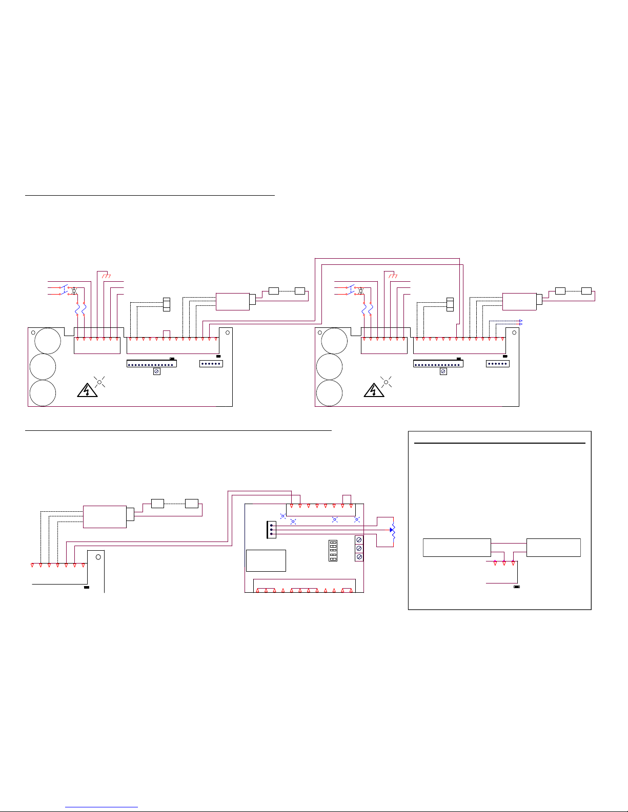
Steps to Monitor the AUX Output with a PLC
Configure the AUX output to source current from
an external power supply to the PLC.
1) Connect the power supply +24 VDC to TB2-2.
2) Connect TB2-1 to the PLC input.
3) Connect the power supply common to the PLC
common.
Note: If the PLC or power supply has any other
connection to the PCB, then R27 must be
removed. Use pliers to twist and snap off R27.
R27 is located behind TB2-1.
PLC Monitor of reconfigured Auxiliary Output
Figure 3
SW3
-
5
FC-40 PLUS
TB2
6
60
7
JUMPER
-
2
+
+
5
FC-40 Plus Subordinate Control
+
S
60 Rev
OPTIC SENSOR
Min
2
AC COMMON
4-20mA
Soft
100K
POT
8
SW4
12
R27
-
LOAD
Direct
3
9
AC HOT
120
-
H1
P/N 111-500
-
SW5
9
J1
TB1
RUN
SIG
Bl
SM312FP1H
11
SENSOR OPTION
OPTICS
43
INTERLOCK INPUT
BOWL/ HOPPER
S
G
S1
+
CONTROL
INTERLOCK OUT P UT
12
10
+
1
+
-
11
7
ACCEPTS BOTH OPTIC AND PROX SENSORS, NPN OR PNP.
8 7
Bu
Br
1
External
RUN
6
P/N 24-210
4
-
VF Series Master Control
Aux Out
-
TRANSFORMER
BANNER
SENSOR
10
Pot I n put
-
+
Sig.
1/8W MIN
MAIN
SIG
+
TB2
cw
56
Max
1
Interlock
CONNECT SINK OR SOURCE WIRE TO "SIG" INPUT
Steps to Interlock Two VF Series Controls together
If a PLC is interfaced to both controls, optical isolation is necessary, see step 4 below.
1. Remove the run jumper from TB2 terminals 8 & 9 of the subordinate control.
2. Add a wire from terminal 3 of the master control to terminal 8 of the subordinate control.
3. Add a wire from terminal 2 of the master control to terminal 7 of the subordinate control.
4. If optical isolation between the controls is desirable, remove R21 from the subordinate control.
Steps to Interlock an FC-40 Plus Series to a VF Series Control
1. Add a wire from terminal 2 of the VF master control to TB2-11 of the subordinate control.
2. Add a wire from terminal 3 of the VF master control to TB2-12 of the subordinate control.
3. Move the run jumper on the subordinate control from TB2-6 & TB2-7 to TB2-5 & TB2-6.
6/1/2017 Page 7
S
1
Bl #14
Enable
BOWL/HOPPER
-
Bl #14
O-
CFR Sensor
P/N 123-215
12
BANNER
S
Load
Out
R21
36
Out -
GND
Keypad
Line
Input
ACCEPTS BOTH OPTIC AND PROX SENSORS, NPN OR PNP.
Gr #14
13 14
+
Chassis
1
Br
BOWL/HOPPER
OPTIC SENSOR
7
Gr #14
Gr/Yl #14
O+
Bl
S
GNDGND
R27
+
+
TB3
L2
LCD Contrast
SENSOR
OPTICS
Bl #14
Out +
L2
F2
E 8
Bu
Br
12 10
Out +
14
CONNECT SINK OR SOURCE WIRE TO "SIG" INPU T
Bl #14
4
LCD Display
11
Gr/Yl #14
TB1
0-10 VDC
-
Bl #14
Analog Gnd .
Analog Gnd .
E
BANNER
S
TB2
L1
OPTICS
+
L1
Bu
SIG SIG
SENSOR OPTIO N
Line
Input
4
LCD Contrast
TB3
E
VF Series Master Control
9
P/N 111-500
LCD Display
+
-
CONNECT SINK OR SOURCE WIRE TO "SIG" INPU T
Br
11 9
TB4
+
-
L2
INTERLOCK OUTPUT
10
Analog
JUMPER
P1
++
Accel.
MASTE R CO NTROL
Aux Out
P1
OUTPUT POWER
-
Bl #14
Bl #14
O-
V+
Bl #14
Bl
RUN
High Voltage L ED
0-10 VDC
7
-
Keypad
L1 2
High Voltage L ED
1
+
GND
1
F1
8
+
Enable
P/N 111-500
INPUT POWER
85 - 264 VAC
+
6
S
+
SENSOR
Danger!
Shock
Hazard
-
+
Bu
ACCEPTS BOTH OPTIC AND PROX SENSORS, NPN OR PNP.
Br
Danger!
Shock
Hazard
(Remove R21 if optical isolation d esired).
SM312FP1H
-
Load
Out
E
1
INPUT POWER
85 - 264 VAC
Aux Out
TB4
5
S
Gr #14
Out -
Accel.
-
L1
OPTIC SENSOR
S
O+
-
Bu
R27
3
CFR Sensor
P/N 123-215
SM312FP1H
Gr #14
TB1
EL2
-
5 2
Analog
-
Chassis
4-20mA
+ +
OUTPUT POWER
R21
INTERLOCK OUTPUT
1
TB2
13
SENSOR OPTIO N
F1
S
VF Series Subordinate Control
E
F2
4-20mA
+
Aux Out
-
S
3 12
R27
TB2
+24 VDC + Input
External
Power
Supply
PLC
0V (Common)(Common) 0V
Page 8
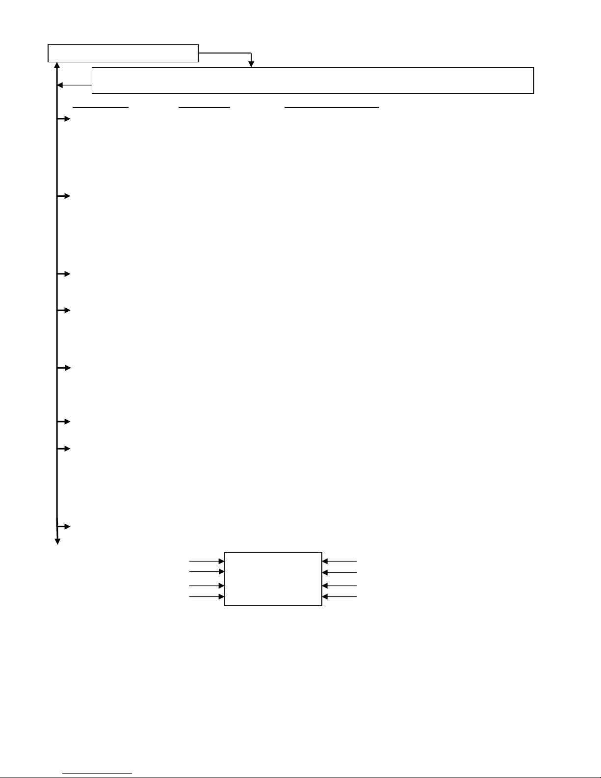
Control Menu Layout for VF-3, VF-9
Normal Operation Display
Power Settings Amplitude [ 0.0 to 100.0 ] %
Max Amplitude [ 100.0 to 40.0 ] %
Min Amplitude [ 0.0 to 95.0 ] %
Soft Start Time [ 0.0 to 10.0 ] Seconds (0.5 Default)
Amplitude Source [ Auto Tracking Manual, 0-10V, 4-20mA,]
CFR Positive Gain [ 25 Default ]
CFR Negative Gain [ 5 Default ]
Main Menu
Frequency Settings Frequency [ 5.0 to 300.0 ] Hz (60.0 Hertz Default)
Max Frequency [ 15.0 to 300.0 ] Hz (140.0 Hertz Default)
Min Frequency [ 5.0 to 290.0 ] Hz (45.0 Hertz Default)
Frequency Mode [ Auto Tracking, Manual ]
Auto Scan [ Press ENTER to perform an automatic frequency scan ]
Resonate Threshold Level [ 200 Default ]
Auto Track Dead Band [ 64 Default ]
Timer Settings On Delay [ 0.0 to 20.0 ] Seconds (0.5 Default)
Off Delay [ 0.0 to 20.0 ] Seconds (0.5 Default)
Empty Bowl Timer [ 5 to 255 ] Seconds (10 Default)
I/O Interface Sensor Polarity [ Inverted, Normal ]
Sensor Type [ Auto, NPN, PNP ]
Run Mode [ Normal, Always On, 2-Speed, High/Low ]
Empty Bowl [ Normal, Stop ]
Aux Output Mode [ Normal, Inverted, Alarm, Inv Alarm, Air Jet ]
Diagnostics Software Version [ Software Revision Level ]
Accelerometer [ data ]
Security Keypad Lock [ Unlocked, Amplitude Only, Locked ]
Security Code [ 000 to 999 ]
Factory Reset [ ‘Enter’ Resets Control to Factory Default Settings (Shown in bold) ]
Language Pick Language [ English, Español (Spanish), Français (French), Deutsch (German) ]
The normal operating display shows the status of the control with regard to input signals and control settings. They are
listed from highest to lowest in priority. The highest priority message takes precedence over the other messages.
Stop/Run - The 1/0 button has been pushed to disable control operation.
Override - The 1/0 button has been pushed and held so the control feeds while ignoring the “Sensor” or “Run” inputs.
Run Input - The run jumper has not been not made.
Parts Sens - The parts sensor and control logic is telling the control to stay off.
Empty/jam - Empty bowl timer has timed out because parts did not pass by the parts sensor to reset the timer.
Analog - An external signal is in control of the speed input.
Low - Low Speed used when 2 speed has been selected and the sensor is not made.
Zero Speed - The output is off because the output is set to 0.0%.
Run – The feeder is running normally.
Run/CFR – Constant Feed Rate sensor is regulating the feed rate (Autotune®).
Press and hold ‘Enter’ key to enter the program menu or get to the security menu. Then use the “Enter”
key to move right from Main Menu to Sub Menu to the Adjustable Setting. Use the “Back” key to move left.
Main Menu
Over Amps [ data, data ]
DC Volts [ data ]
Internal Temperature [ data ] °C
Adjustable Setting Sub Menu
Defaults Restore Settings 1 [ ‘Enter’ Restores User Settings 1 ]
Restore Settings 2 [ ‘Enter’ Restores User Settings 2 ]
Restore Settings 3 [ ‘Enter’ Restores User Settings 3 ]
Status Line Message
CFR Set Point
Amplitude
Frequency
Save Settings 1 [ ‘Enter’ Saves User Settings 1 ]
Save Settings 2 [ ‘Enter’ Saves User Settings 2 ]
Save Settings 3 [ ‘Enter’ Saves User Settings 3]
Normal Display Message Priority
Run/CFR R=1
CFR=024.5
A= 40.0% O=1
F= 60.0Hz A=1
S=1
Run Input: 1= on /closed & 0= off/open
Sensor Input: 1= on /closed & 0= off/open
Output to vibratory feeder: 1= on & 0= off
Aux Output: 1= on & 0= off
VF-3-9 Menu Ver1_28.doc 10/30/2013
Press 1/0
Page 9
INSTALLING THE CFR SENSOR
Note: Failure to adequately prepare the feeder’s
surface properly may result in a Constant Feed
Rate (CFR) sensor that will not bond to the
feeder. The sensor should not be mounted until
step C-6.
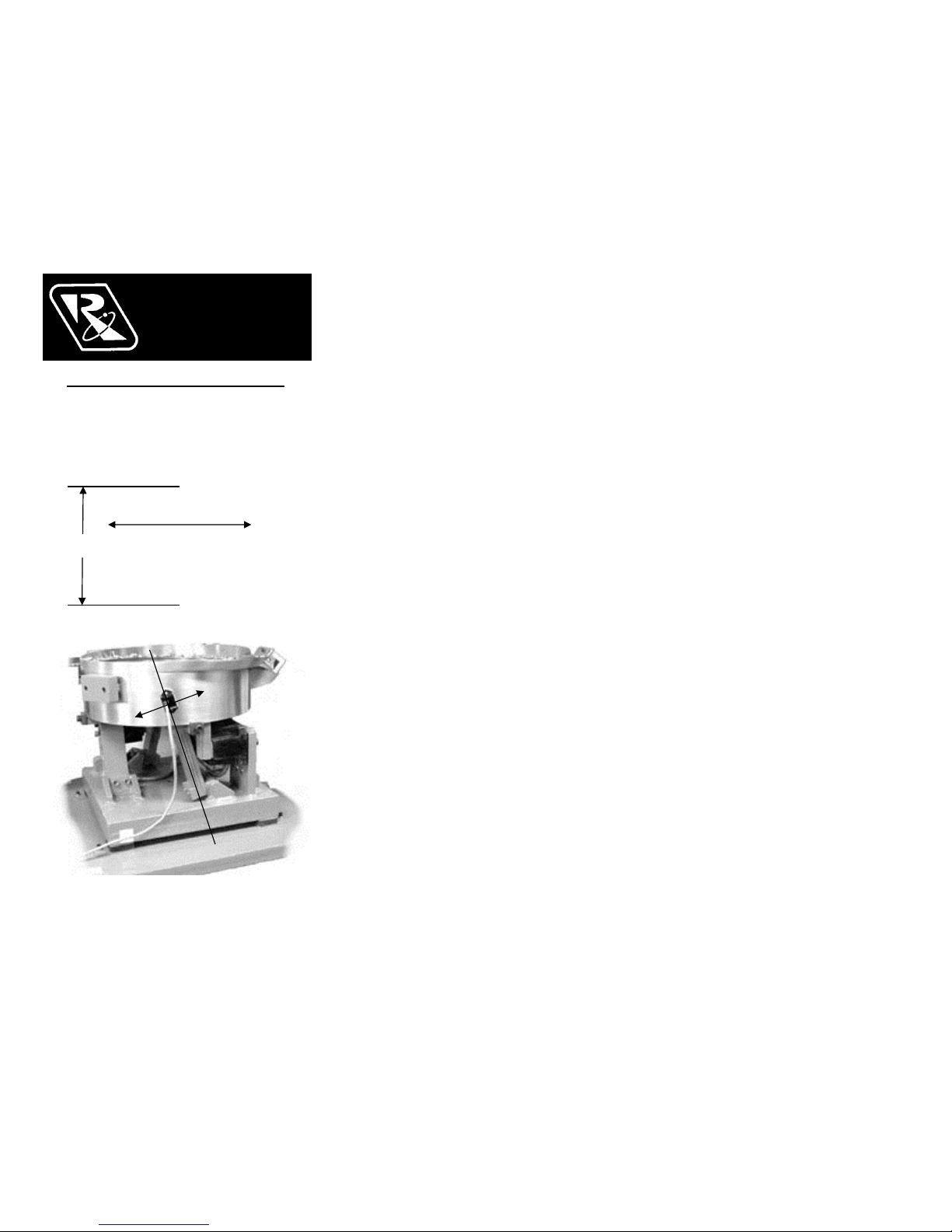
Fig. 2 The arrow shows the direction of vibration
which is at a right angle to the spring pack.
A. ORIENT THE SENSOR so that its sensitive axis
is in the same direction as the vibration of the
feeder. The double-ended arrow in figure 1 shows
the sensor’s sensitive axis. Align the sensitive axis of
the sensor in the same direction as the vibration (see
figure 2). The sensor must be oriented correctly for
proper operation.
B. CHOOSE A LOCATION for mounting the sensor
on the feeder that is smooth and that will allow the
adhesive on the sensor to bond. Avoid mounting the
sensor over ridges and bumps which can reduce the
ability of the adhesive to stick to the feeder. The
correct location will also have enough space for the
sensor’s cable to hang straight down without touching
anything else.
C. SURFACE PREPARATION of the feeder is crucial
for proper bonding between the sensor and the feeder.
Please follow these steps completely.
1) The feeder should be kept between 70 and 100 F
for ideal tape application.
2) Clean a three and one-half inch circular area with a
solvent like isopropyl alcohol that will not leave a
residue. As a rule of thumb, the area can be
considered clean when after cleaning the area with a
solvent-saturated, white paper-towel, the towel is as
clean as it was before wiping.
3) Using a good amount of pressure, polish the
cleaned, circular area of the feeder using a scratch
pad or steel wool. Repeat step 2, and then go to
step 4.
4) Wipe the cleaned surface with an alcohol wipe or
with a 50/50 isopropyl alcohol/water combination.
5) Dry the surface thoroughly using a low lint cloth or a
clean paper towel.
6) Remove the vibration sensor from its protective
packaging. Remove the liner from the adhesive
backing. Avoid touching the tape. Align the sensor
as shown in figures 1 and 2. Apply the vibration
sensor to the prepared area of the feeder. Press the
sensor very firmly onto the feeder surface for at least
10 seconds.
7) Allow the vibration sensor at least 20 minutes to
cure before operation. Note: It takes 72 hours for the
adhesive to fully cure at 70 F.
Alternatively, #8 or M4 screws can be used to mount
the sensor to the feeder. The mounting holes are
1.375” (3.49cm) apart.
D. ROUTE THE SENSOR CABLE to protect it from
strain due to vibration. The cable that attaches to the
sensor will not break from normal vibration; however,
some care should be used when routing the sensor
cable from the sensor to the control. The cable should
hang straight down from the sensor without touching
the feeder bowl or anything else. Then, the sensor
cable should curve towards the power control with
a bend radius larger than 3 inches.
Use a cable tie and an adhesive-backed mount to
attach the sensor cable to the side of the drive
base. See Figure 2. Clean the mounting area
before applying the adhesive-backed mount.
E. CONNECT THE SENSOR to the control. If
needed, connect the sensor cable’s brown wire to
“+ACCEL” on TB2. The blue wire connects to the
“–ACCEL” on TB2.
F. SELECT THE SENSOR in the software settings
of the control menu. See the Control Menu Layout
page for a visual layout of the program menu.
1) Press and hold the “Enter” key to enter the main
menu.
2) With “Power Settings” displayed, press the
“Enter” key to get into the submenu.
3) Arrow “Down” to select the “Amplitude Source”
submenu.
4) Press the “Enter” key, and Arrow “UP” to select
“Auto Tracking” from the adjustments.
5) Press the “Back” key twice to get back to the
main menu.
6) Next, arrow “Down” to the “Frequency Settings”
selection.
7) Press the “Enter” key to get into the submenu.
8) Arrow “Down” to select the “Frequency Mode”
submenu.
9) Press the “Enter” key, and Arrow “UP” to select
“Auto Tracking” from the adjustments.
10) Press the “Back” key three times to get back to
the normal running display.
G. PERFORM AUTO SCAN of the vibratory
feeder. See the Control Menu Layout page for a
visual layout of the program menu.
1) Press and hold the “Enter” key to enter the main
menu.
2) Arrow “Down” to select the “Frequency”
submenu.
3) Press the “Enter” key, and Arrow “UP” three
times to select “Auto Scan” from the adjustments.
4) Press the “Enter” key to perform an automatic
frequency scan.
RODIX, INC.
Toll Free (800) 562-1868
E-mail [email protected]
www.rodix.com
© 2005 RODIX INC. VF-9 CFRsensor 171704.doc
RODIX INC.
FEEDER CUBE
VF SERIES CFR SENSOR
CONSTANT FEED RATE
P/N 123-215
Sensitive
Axis of
Vibration
Fig. 1
Actual Size
1.375”
Page 10
RODIX SOLUTION
Good wiring practices for
avoiding electrical noise
problems.
Rodix controls have been designed with a
high degree of immunity to electrical
noise; however, depending on the control
installation, electrical noise can cause
problems. These problems occur in less
than 1% of the product installations. Most
electrical noise problems can be avoided
by following some simple guidelines.
Good wiring practices need to be used to
prevent electrical noise from interfering
with your control’s operation. Another
name for electrical noise is ElectroMagnetic Interference (EMI).
Symptoms of Electrical Noise
The symptoms of electrical noise would
appear as follows: a brief pause or a brief
“bump” in the vibratory feeder’s output
that the control automatically recovers
from. In rare cases the control will either
stop operating or run continuously at full
power in 120 pulse mode until the power
switch is slowly cycled OFF and ON.
Sources of Electrical Noise
Electrical noise is generated by devices
like relay coils, solenoid valves,
contactors, servo motors, and variable
frequency inverter drives. The electrical
noise is then transferred to another device
by one of three ways. The noise could be
conducted through the power wires, or
capacitively coupled from wire to adjacent
wire, or it is transmitted from the wires of
a nearby noise source.
Solutions for Electrical Noise
1. Use shielded wires for all I/O (Input /
Output) signals. The I/O signals may
include: 4-20mA input, Run input, Sensor
input, 0-5VDC input, Interlock input or
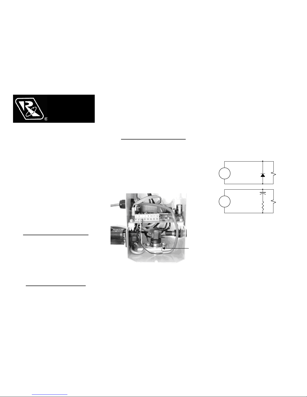
AUX output. The shield “drain” wire
should be tied to the chassis in the Rodix
control. The drain wire should be kept
shorter than 2”. Please see the enclosed
picture.
Example of a “drain” wire termination
2. Never run I/O signal wires in the same
conduit or raceway as AC power lines
such as wires to motors, solenoids,
heaters, welders and Rodix controls, etc.
3. I/O wires within an enclosure should
be routed as far away as possible from
relays, solenoids, transformers, power
wiring and other noisy equipment. Keep
the I/O signal wires separate from the
control’s input and output power wiring.
Secure the wires in place.
4. Whenever relays or solenoid valves
are used, install a Snubber on them to
reduce electrical noise. Use a diode on a
DC coil. Use a RC Snubber on an AC
coil.
5. In extremely high EMI environments,
Power Line Filters and ferrite beads can
be effective. Install ferrite beads on I/O
signal wires as close as possible to the
circuit board terminal strip. Loop the wire
through the bead several times or use
several beads on each wire for additional
protection.
RODIX, INC.
Toll Free (800) 562-1868
E-mail [email protected]
www.rodix.com
2000,2014 RODIX INC. Good Wiring 1/31/2014
RODIX INC.
FEEDER CUBE
RODIX SOLUTION .408
Drain
Wire
RELAY
COILSNUBBER
VAC
104M06QC47
QUENCH-ARC
RECTIFIER
DIODE
RELAY
COIL
1N4006
VDC
+
-
 Loading...