

Rodenstock REM 3000 Instruction Manual

INSTRUCTION MANUAL
If you have questions about operations, please contact
SPECULAR MICROSCOPE
REM 3000
Carefully read this instruction manual before using this
instrument to ensure correct and safe operation.
RODENSTOCK or our local distributor.
■ Always follow the operation procedures
described in this manual.
■ Keep this manual in a readily available
location while operating the instrument.
■ Contact our local distributor if you lose
this instruction manual.
602F9090-00


i Important Safety Information
n
Do not install this instrument in a location where explosives or inflammable
substances are used or stored. Otherwise, fires or explosion may occur.
n
Do not remove the cover of the instrument. Otherwise, you may be directly
exposed to high voltage sections.
n
Do not disassemble or modify the instrument. Otherwise, you may be
directly exposed to high voltage sections.
n
Do not look straight at any alignment laser light emitted from the measuring
section.
n
Disconnect the power cord from the instrument before servicing the
instrument. Otherwise, you may get an electric shock.
n
Do not place water or chemicals on the instrument. Any water or chemicals
entering the instrument may cause an electric shock or failure.
n
Only use the specified terminal for connection of the instrument. Using
another type of terminal may result in failure of the instrument.
n
This instrument is a diagnostic/measuring device specially designed for
ophthalmology. Never use the instrument for other purposes.
n
The external output terminal is not isolated from the internal circuit.
Inappropriate wiring may damage the internal circuit. If you wish to
connect this instrument to other devices, contact our local distributor or
RODENSTOCK.
i-1
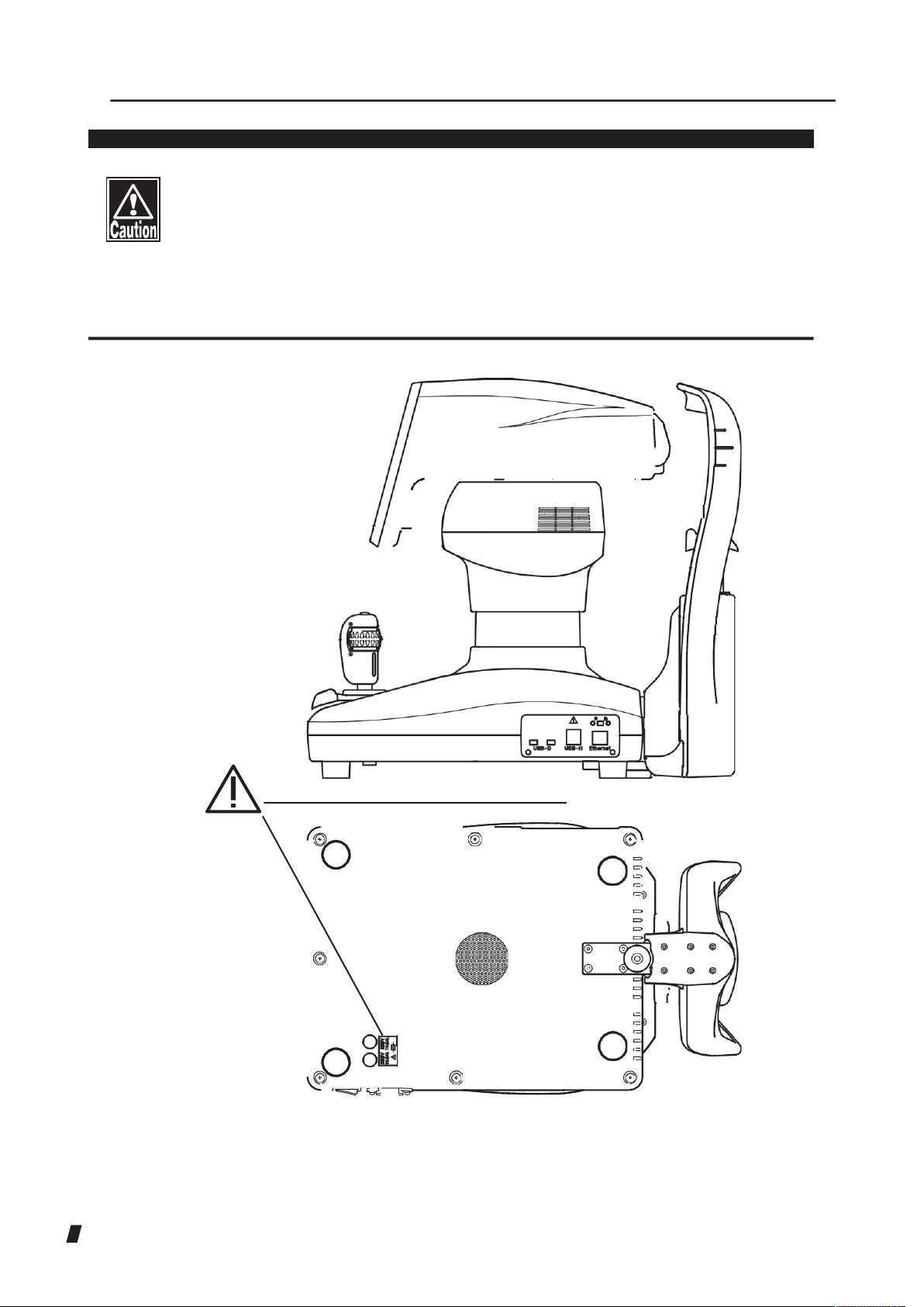
Caution label
n
Never damage or cause caution labels provided for the instrument to
become illegible. A caution label is provided on the back side of the
instrument.
n
If a label is damaged or becomes illegible, please contact
RODENSTOCK or our local distributor.
i-2

ii How to Read This Manual
Outline
This manual is structured as follows.
1. PRIOR TO USE
Describes safety precautions and important information to
be understood before installing and using the instrument.
2. NAMES AND FUNCTIONS OF PAR TS AND
COMPONENTS
Describes names and functions of each section of the
instrument.
3. PERATION PROCEDURES
Describes information required for installing and using the
instrument.
4. TECHNICAL INFORMATION
Describes useful technical information about the
instrument.
5. INSPECTION AND MAINTENANCE
Describes procedures for replacing consumable parts, etc.
that the user of the instrument should normally conduct.
6. TROUBLESHOOTING
Describes how to solve problems.
7. CONSUMABLES AND OPTIONAL EQUIPMENT
Describes consumable parts and optional equipment.
8. SPECIFICATIONS
Describes the specifications of the instrument.
9. INDEX
Refer to the index when needed.
ii-1
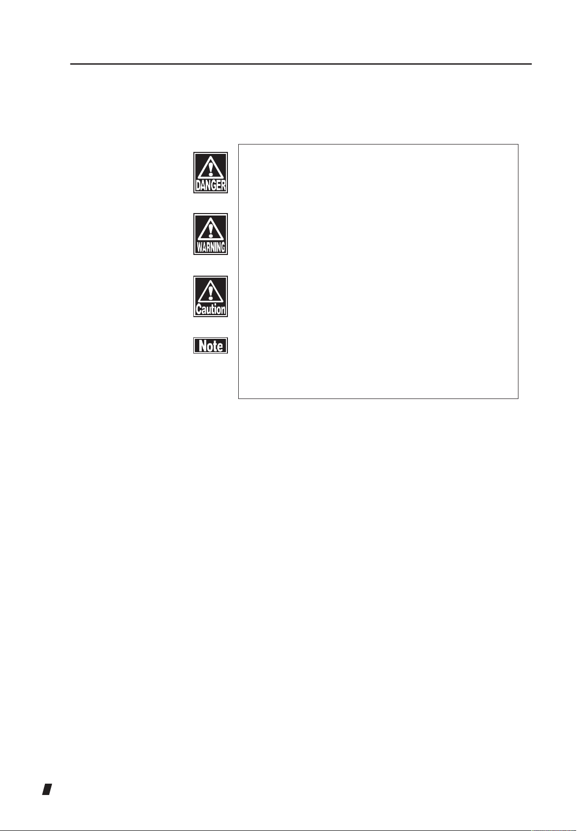
n
This is a precaution that, if unheeded, will result in a
hazardous situation where there is an imminent
danger of serious injury or death.
n
This is a precaution that, if unheeded, could result
in a hazardous situation where there is a possibility
of serious injury or death.
n
This is a precaution that, if unheeded, may result in
a situation where there is a possibility of minor or
moderate injury or damage to property.
n
This is an additional instruction which may
contain a special precaution on company policy
related, either directly or indirectly, to the safety of
personnel or to the protection of property.
SYMBOLS USED IN THIS MANUAL
The symbols below indicate the following:
ii-2

iii Contents
i Important Safety Information ................................................................................................ i-1
ii How to Read This Manual................................................................................................... ii-1
Outline............................................................................................................................ ii-1
SYMBOLS USED IN THIS MANUAL ............................................................................. ii-2
iii Contents............................................................................................................................ iii-1
1. PRIOR TO USE ................................................................................................................ 1-1
1.1 Precautions for operation ....................................................................................... 1-1
1.2 Checking contents of package ............................................................................... 1-5
1.3 Glossary ................................................................................................................. 1-6
1.4 Outline of operation ................................................................................................ 1-8
2. NAMES AND FUNCTIONS OF PARTS AND COMPONENTS ......................................... 2-1
2.1 Physician's side ...................................................................................................... 2-1
2.2 Patient's side .......................................................................................................... 2-4
2.3 Screen .................................................................................................................... 2-5
2.4 Operation of the joystick ....................................................................................... 2-13
2.5 Touch Alignment ................................................................................................... 2-14
3. OPERATION PROCEDURES .......................................................................................... 3-1
3.1 Installation .............................................................................................................. 3-1
3.1.1 Precautions for installing the instrument ........................................................ 3-1
3.1.2 Precautions for connecting the power cord .................................................... 3-2
3.2 Preparation before use ........................................................................................... 3-3
3.2.1 Connecting the power cord ............................................................................ 3-3
3.2.2 Connecting an external digital printer ............................................................. 3-3
3.2.3 Connecting external ID input device .............................................................. 3-4
3.2.4 Connecting DATA Transfer ............................................................................. 3-4
3.2.5 Starting ........................................................................................................... 3-5
3.2.6 Setting ............................................................................................................ 3-5
3.3 Capturing Images ................................................................................................... 3-6
3.3.1 Precautions .................................................................................................... 3-6
3.3.2 Entering patient information ........................................................................... 3-6
3.3.3 Patient's eye height adjustment ..................................................................... 3-9
3.3.4 Changing sight-fixing lamp position ............................................................. 3-10
3.3.5 Alignment ..................................................................................................... 3-11
3.3.6 Capturing endothelial images ....................................................................... 3-13
3.3.7 Captured Image Selection ............................................................................ 3-16
iii-1

3.3.8 Analysis result screen .................................................................................. 3-19
3.3.9 Dark Area Analysis screen ........................................................................... 3-23
3.3.10 Editing the extracted edges ......................................................................... 3-24
3.3.11 Analytical calculation using the L-count function ......................................... 3-26
3.3.12 Displaying reliability ...........................................................................
3.4 Recalling data in the memory ............................................................................... 3-30
3.5 Data communication ............................................................................................ 3-31
3.5.1 Sending examination data ........................................................................... 3-31
3.6 Setting .................................................................................................................. 3-33
3.6.1 Common ...................................................................................................... 3-34
3.6.2 Function ....................................................................................................... 3-35
3.6.3 Printer .......................................................................................................... 3-37
3.6.4 Export .......................................................................................................... 3-38
3.6.5 LAN .............................................................................................................. 3-40
3.6.6 Information ................................................................................................... 3-41
4. TECHNICAL INFORMATION ........................................................................................... 4-1
5. INSPECTION AND MAINTENANCE ................................................................................ 5-1
5.1 Warranty ................................................................................................................. 5-1
5.2 Durable years ......................................................................................................... 5-2
3-28
5.3 Inspection ............................................................................................................... 5-2
5.4 Routine maintenance ............................................................................................. 5-3
5.4.1 Forehead pad/Chin rest ................................................................................. 5-3
5.4.2 Outer surface ................................................................................................. 5-3
5.5 Replacing consumables ......................................................................................... 5-4
5.5.1 Fuses ............................................................................................................. 5-4
5.5.2 Chin rest paper .............................................................................................. 5-4
5.6 Storing .................................................................................................................... 5-5
5.7 Disposal ................................................................................................................. 5-6
6. TROUBLESHOOTING ..................................................................................................... 6-1
7. CONSUMABLES .............................................................................................................. 7-1
8. SPECIFICATIONS ........................................................................................................... 8-1
8.1 Specifications ......................................................................................................... 8-1
8.1.1 Capturing scope ............................................................................................. 8-1
8.1.2 Corneal thickness measurement accuracy .................................................... 8-1
iii-2
8.1.3 Main unit ........................................................................................................ 8-1
8.1.4 Power source ................................................................................................. 8-1
8.2 Noise ...................................................................................................................... 8-2

8.3 Operating environment ........................................................................................... 8-2
8.4 Classification .......................................................................................................... 8-3
8.5 Declaration of conformity with EMC ....................................................................... 8-3
9. INDEX ............................................................................................................................... 9-1
iii-3

This page is intentionally blank
iii-4

1. PRIOR TO USE
n
Read this manual thoroughly before using the
instrument to ensure proper and safe operation.
n
Always follow the operation procedures described
in this manual.
n
Check that there is no device that generates
strong magnetic fields near the instrument. Strong
magnetic fields may cause noise and affect the
measurement.
1.1 Precautions for operation
n
Only allow adequately skilled operators to use the instrument.
n
Precautions for installing the instrument
Install the instrument in a location free of water or chemicals. Any water
or chemicals entering the instrument may cause an electric shock or
failure.
Do not install the instrument in a place where chemicals are stored or
gases may occur. Spilt chemicals or vapor may enter the instrument and
ignite.
Check the frequency, voltage, and allowable current (or power
consumption) of the power source. Operating the instrument connected
to an inappropriate power source may cause fire or an electric shock.
Connect the power plug to a grounded 3P-outlet. Otherwise, a short
circuit due to failure of the instrument may result in an electric shock.
Do not place any heavy object on the power cord or squash the power
cord. Connecting such a device may cause fire or an electric shock.
Completely insert the power plug into the outlet. Faulty contact, allowing
any metal to contact exposed plug terminals, or dust accumulated on
exposed plug terminals may result in fire or an electric shock.
Do not connect any device with data transmission specifications that are
not compatible with the instrument. Connecting such a device may cause
a fire or an electric shock. If you wish to connect this instrument to other
devices, contact our local distributor or RODENSTOCK.
Ground the instrument appropriately. Otherwise you may get an electric
shock.
1-1

Do not hold the head unit, chin rest, forehead pad, or joystick when lifting
the instrument. These components are detachable and the instrument
may drop, resulting in injuries.
Install the instrument in a location not subject to direct sunlight, high
temperature and humidity, or air with significant dust, salt, and/or sulfur
content. These may cause failure or malfunction of the instrument.
Install the instrument in a level and stable location free of vibration and
mechanical impacts to ensure correct capturing, and prevent the
instrument from falling or being dropped, which can result in fire or fatal
accidents.
Install the instrument between the patient and physician so that they can
face with each other.
Install the instrument in a location that it is sufficiently clear of any other
equipment that may interfere with the examination when using the
instrument.
n
Precautions before using the instrument
Check that all cables are connected correctly and completely.
Check the sections that the patient will directly touch.
Peel off the top sheet of chin rest paper and clean the forehead pad with
a cloth dampened with alcohol before capturing.
Check that the instrument is correctly grounded.
Check that the date set in the instrument conforms to the actual operation
date and time.
When the room temperature lowers to 10°C or below in winter, turn the
instrument on and warm it up before starting operation. Low temperature
may affect the image quality.
n
Precautions during operation
Do not place any container with liquid in it on the instrument. Any liquid
entering the instrument may cause an electric shock or failure.
Do not operate the joy stick, touch panel, and membrane switch during
initial operation until the capture screen appears after turning the power
switch on. If the initial operation is not complete properly, malfunction may
occur during capturing.
If any smoke, offensive odor, or abnormal sound occurs, turn off the
instrument immediately, disconnect the power plug from the outlet, and
contact our local distributor or RODENSTOCK.
When moving the head unit and/or chin rest of the instrument, pay
attention to the position of the patient's face, hands, and fingers. The
patient may be injured by the moving section of the instrument.
1-2

Do not allow any person to place their hands or fingers in the clearance
under the head unit or the section under the chin rest. Their hands or
fingers may be crushed and injured.
Do not place any finger or object through the capturing window. These
may cause malfunction or failure of the instrument and/or an inaccurate
analysis result.
Do not lean on the instrument or press on the instrument from the top. The
instrument may fall, resulting in mechanical failure or injuries.
Complete the capturing within the prescribed time and number of
repetitions.
Observe both the instrument and patient to ensure there are no problems.
If a problem with the instrument or the patient occurs, take appropriate
action such as stopping the machine to ensure the safety of the patient.
Halt the operation immediately if the patient shows any sign of
photosensitive epilepsy while capturing images.
Poor fixation, blepharoptosis, trichiasis, or corneal disease may cause
inaccurate analysis results or corneal thickness measurements.
If the captured image is not clear, analyze another image or capture a new
image.
When using the photographing and analysis results by this instrument for
diagnosis, also conduct other examinations and carefully consider the
results of those examinations to make final judgment. Capturing
conditions may affect the precision of captured images or analysis
results.
Do not use the “corneal thickness” and “ultrasonic correction for corneal
thickness” output from this instrument to directly correct the eye refractive
power. Other examination methods should also be used in conjunction
with the above.
Do not allow the patient to touch the instrument.
Peel off the top sheet of chin rest paper and clean the forehead pad with
a cloth dampened with alcohol before the next patient.
n
Precautions after operation
Do not place any container with liquid in it on the instrument. Any liquid
entering the instrument may cause an electric shock or failure.
Do not use organic solvents such as thinner, benzene, or acetone to clean
the instrument. This may cause fire or an electric shock. (These can also
corrode the resin or coating of the instrument cover.)
Hold the plug when disconnecting the power plug from the outlet to avoid
applying excessive force on the cord. Pulling the cord may damage inner
core wires, resulting in electric shock or fire.
1-3

Disconnect the power plug when the instrument is not operated for a long
period of time.
Refer to “5.6 Storing” for instructions on storing the instrument.
Clean the instrument appropriately at the end of operation to get ready for
the next operation.
Clean and neatly arrange the accessories and cables.
If any smoke, offensive odor, or abnormal sound occurs, turn off the
instrument immediately, disconnect the power plug from the outlet, and
contact our local distributor or RODENSTOCK.
n
If any instrument failure occurs, stop operation immediately, indicate
the failure, and contact our local distributor to request repair.
Never modify the instrument. Doing so may cause electric shock or failure
of the instrument. The instrument contains high-voltage sections.
Touching these sections will result in death or serious injuries.
Disconnect the power plug from the outlet when replacing fuses.
Otherwise you may get an electric shock, resulting in death or serious
injuries.
Use the power cord and fuses provided with the instrument or specified
by RODENSTOCK to ensure safety. Also, do not use the accessories
provided with the instrument for other equipment.
When any instrument failure occurs, indicate the failure, and contact our
local distributor to request inspection and repair. Do not attempt to repair
the instrument yourself.
Conduct regular inspections of the instrument and components.
When the instrument is not used for 1 month or longer, refer to “5.3
Inspection” in this manual and check that the instrument is operating
correctly and safely before starting operation.
1-4

1.2 Checking contents of package
Open the package and check that the specified amount of
the following items are included in the package and are not
damaged. If any item is missing or damaged, contact our
local distributor as soon as possible.
n
Keep the box and packing materials for use when
moving or transporting the instrument.
n
When taking the instrument out of the box, pull the
outer box upward and then remove the packing
materials. Be careful not to lift the instrument by
directly holding the head unit, chin rest, forehead
pad, or joystick. Otherwise, the instrument could be
damaged.
● Main unit ......................................................................... 1
● Power code ............................................................. 1
● Fuses (2 fuses are installed in the main unit) .......... 4
● Chin rest paper ........................................................ 1
● Pins for Chin rest paper ........................................... 2
● Dust cover ............................................................... 1
● INSTRUCTION MANUAL (this book) ...................... 1
● DATA Transfer Installation CD ................................. 1
● DATA Transfer startup guide ................................... 1
1-5

1.3 Glossary
[AA] : Auto Alignment. (Refer to [Auto Alignment].)
[AS] : Auto Shot. (Refer to [Auto Shot].)
[AVG] : Indicates the average dimension of the analyzed endothelial
cells.
[CCT] : Corneal thickness.
[CCT(US)] : Ultrasonic correction for corneal thickness. The reference
value expected when measuring the same corneal thickness
using our ultrasonic pachymeter (SP-100, etc.).
[CD] : Indicates the density of the analyzed endothelial cells as the
number of cells per 1 mm2.
[CV] : Indicates the coefficient of variation of the analyzed
endothelial cells, derived by dividing standard deviation by
the average dimension.
[DAD] : Density of the analyzed dark area represented as the
number of cells per 1 mm2.
[DATA Transfer] : System that outputs the examination data from
RODENSTOCK products to digital files.
[Dark Area] : Black circle area to be observed by the specula microscope.
[L-count] : Method where the physician performs analytical calculation
by selecting cells on the screen.
[MA] : Manual Alignment. (Refer to [Manual Alignment].)
[Max] : Indicates the dimension of the largest analyzed endothelial
cell.
[Min] : Indicates the dimension of the smallest analyzed endothelial
cell.
[MS] : Manual Shot. (Refer to [Manual Shot].)
[Number] : Indicates the number of analyzed endothelial cells.
[Polymegathism] : Represents the difference in sizes and shows the distribution
of endothelial cell dimensions in a histogram.
[Plemorphism] : Represents plemorphism and shows the distribution of
endothelial shapes in a histogram.
1-6

[Quick mode] : Stores captured images of a right eye and left eye in the
memory, and allows you to display, print, and/or send the
image data of both eyes.
[Ratio] : Displays the ratio of the dark area size relative to the total
area. The total area is the sum of the analyzed dark area
and the area of analyzed endothelium tissues.
[SD] : Indicates the standard deviation of the analyzed endothelial
cell dimensions.
[Standard mode] : Temporarily stores captured images of ten eyes (regardless
of right or left eye) in the memory.
[Auto Mode] : Mode that automatically conducts alignment and capturing.
[Auto Alignment] : Function that automatically aligns the sight in up/down/right/
left focus directions.
[Auto Shot] : Function that automatically starts measurement when the
patient's eyes are within the measuring range.
[Auto Power Off] : Function that automatically turns the LCD off, with only the
power lamp flashing, when the instrument is not operated for
the specified time (Auto Power Off mode). Touch any button
to return to Normal mode.
[Touch Alignment] : Allows you to move the head unit by touching the screen.
This is used for rough alignment.
[Touch Panel] : Allows you to make various settings and execute the touch
alignment function by directly touching the screen.
[Manual Mode] : Mode that manually conducts alignment, switching to an
enlarged screen, and image importing.
[Manual Alignment] : Mode that allows you to perform alignment manually.
[Manual Shot] : Mode that allows you to capture images manually.
1-7

1.4 Outline of operation
The REM 3000 is a Corneal Endothelium Analyzer, which captures images of the corneal
endothelial cells of a patient's eye, automatically analyzes captured images, and calculates the
cell density. It is also equipped with a corneal thickness measurement function.
The patient places her chin on the chin rest and looks into the sight-fixing lamp in the capturing
window.
After the physician observes the patient's eye on the monitor screen and roughly aligns the
capturing position, fine alignment and capturing are automatically conducted.
When the endothelial cells cannot be captured automatically, align the capturing position with the
joystick and press the joystick button to start capturing.
Once the capturing process begins, a green LED will shine on the patient's eye and a corneal
endothelial image will be captured. By pushing the ANALYSIS switch after the image has been
captured, various parameters for cell dimensions and cell shapes will be automatically calculated.
1-8
⑤
2. NAMES AND FUNCTIONS OF PARTS
AND COMPONENTS
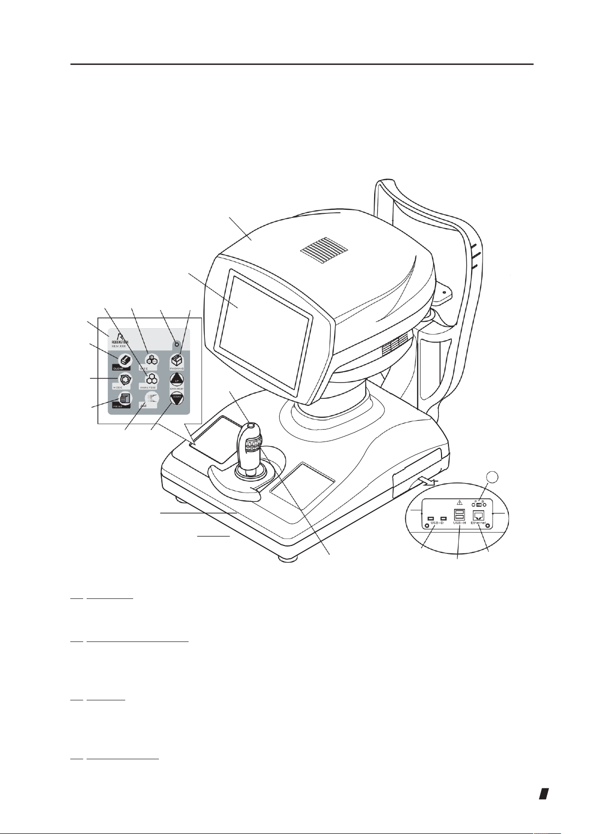
2.1 Physician's side
①
⑬ ⑫
②
⑰ ⑮
⑦
⑧
⑨
⑩
④
⑪
⑯
⑭
21
③
⑥
⑱
(1) Head unit
Section that conducts image capture.
⑲
⑳
(2) Monitor / touch panel
Displays the capturing screen and various setting screens. Touch the touch panel buttons
shown on the monitor to make various settings and operate the instrument.
(3) Joystick
Tilting the joystick to the right, left, back, and forth moves the head unit to the right, left,
forward, and backward for fine positioning.
(4) Joystick button
Starts capturing images.
2-1

(5) Up/down ring
Moves the head unit up and down. Moving the ring up and down moves the head unit for
rough positioning. Turning the ring moves the head for fine positioning.
(6) Hand rest
Place your hand on the rest to operate the joystick. Sliding the rest forward, backward, to the
right, and left moves the head unit in the corresponding direction for rough positioning.
(7) Eye level mark
Reference mark when aligning the height of the patient's eye
(8) Membrane switch
Used to make various settings and operations.
(9) “CLEAR” switch
Deletes all the examination data.
(10) “MODE” switch
Switches the alignment mode between automatic and manual.
(11) “PRINT” switch
Prints the captured result on a connected external printer.
(12) “ANALYSIS” switch
Analyzes the captured endothelial image automatically.
(13) Link switch
Connects to the external devices to send data.
(14) “PACKING” switch
Pressing this button for 3 seconds moves the head unit to the lowest position for packing (lower
dead center).
(15) “CHIN REST” switch
Touching the UP and DOWN buttons moves the chin rest up and down respectively.
(16) Power lamp
Stays lit while the instrument is turned on.
(17) USB-D connectors
Connect the PC and printer here. There are two ports.
(18) USB-H connector
Connects the barcode reader, card reader, and supported digital printers. There are two
ports.
2-2

(19) LAN connector
Connect the LAN cable here.
(20) Maintenance switch
This switch is reserved for use by servicemen performing maintenance work. Do not operate
this switch.
2-3
(4)
(1)
3)
(6)
(5)
(7)
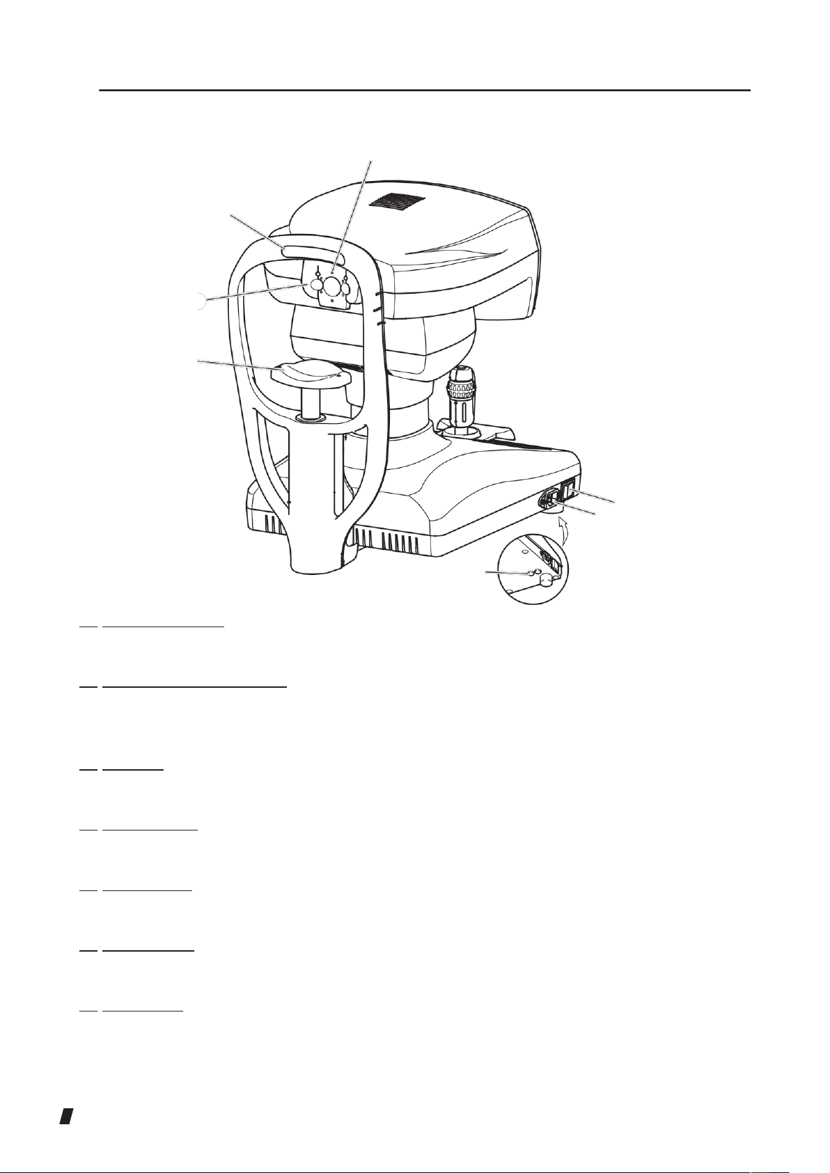
2.2 Patient's side
(
(1) Capturing window
The patient's endothelium is illuminated and captured through the capturing window.
(2) Peripheral sight-fixing lamp
When an image of the cornea periphery is being captured, the patient is prompted to stare at
the peripheral sight-fixing lamp.
(3) Chin rest
The patient places their chin on this rest.
(4) Forehead pad
The patient presses their forehead against this pad.
(5) Power switch
Press the [I] or [O] side to turn the instrument on or off respectively.
(6) Power socket
Connect the power cord here.
(7) Fuse holder
Insert the fuses here.
(2)
2-4
#WVQ
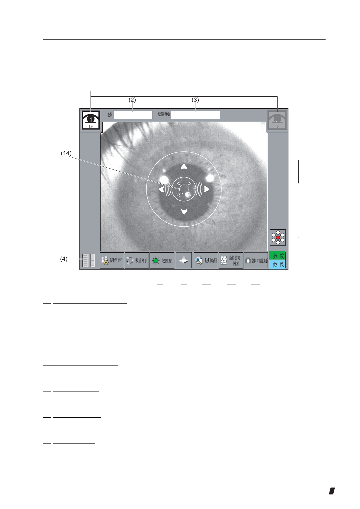
2.3 Screen
<Capturing Screen>
(1)
(5) (6) (7)
(8) (9) (10) (11) (12)
(1
(1
(1) Eye display button [R]/[L]
Displays the right or left eye on which the head unit is positioned, using the corresponding
color. Touch this icon to move the head unit when changing the eye to be examined.
(2) ID number [ID] Displays
the ID number.
(3) Patient's name [Name]
Indicates the patient's name.
(4) Chin rest height
Displays the current chin rest height according to the preset 6 levels.
(5) Head unit height
Displays the current head unit height according to the preset 11 levels.
(6) “Setup” button
Sets operation conditions for each function.
(7) “Mode” button
Switches the alignment mode between automatic and manual.
2-5

(8) Illumination light adjusting button
Adjusts the brightness of the illumination light.
(9) Head unit retract button
Retracts the head unit while the button is pressed.
(10) “Data” button
Recalls the data saved in the memory. This button does not appear in Quick mode.
(11) “Zoom” button
Switches the anterior eye segment image to the endothelial image when the manual mode is
used.
(12) “Capture” button
Captures the endothelial image when the button is pushed in manual mode viewing a zoomin endothelial image.
(13) Sight-fixing button
Displays the currently set position of the sight-fixing lamp. Push this button to select the
position of the sight-fixing lamp.
(14) Target ring
Index reference used when aligning the patient's eye position for capturing the image. When
Touch Alignment is ON, the head unit moves toward the eye while this icon is pressed.
(15) Focus indicator
Displays the distance between the head unit and the patient's eye. When bars appear
horizontally, the head unit is too far from the eye. When bars appear vertically, the head unit is
too close to the eye.
2-6
㪘㫉㪼㪸
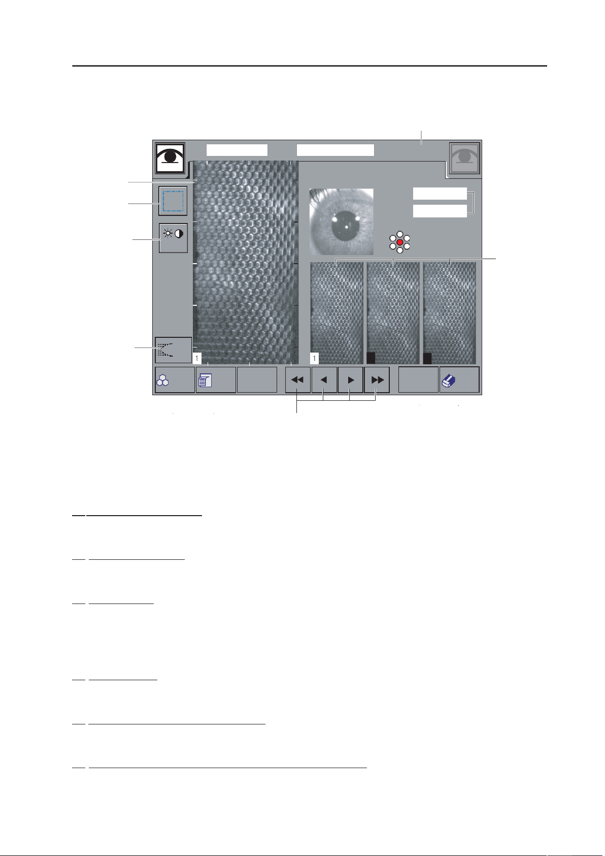
<Captured Image Selection Screen>
(15)
㪠㪛
1&
4
(1)
(3)
㪫㫆㫅㪼
㪜㫏㫇㫆㫉㫋
㪘㫅㪸㫃㫐㫊㫀㫊
㪧㫉㫀㫅㫋 㪥㪼㫏㫋 㪜㫐㪼
(4)
(10)
㪥㪸㫄㪼
_07/ 2/24 24:00
㪚㪚㪫
㪚㪚㪫㩿㪬㪪㪀
㱘㫄
㱘㫄
15
.
(14)
(5)
(6)
(2)
2
3
㪩㪼㫋㪸㫂㪼
㪚㫃㪼㪸㫉
(13)
(7) (8) (9) (11)
(12)
(1) Selected Image display
Displays the selected image.
(2) Captured image list
15 captured images are displayed from the best condition to the worst.
(3) “Area” button
Manually specifies the area to be analyzed from the captured image.
When performing analytical calculation using the L-count function, touch the “Area” button,
and the “L-count” button appears.
(4) “ Tone” button
Adjusts brightness for displaying captured endothelium images.
(5) Anterior eye segment image display
Displays the captured anterior eye segment image.
(6) Sight-fixing lamp position display at the time of capturing
Displays the position of the sight-fixing lamp when the image was captured.

2-7

(7) “Analysis” button
Automatically analyzes the selected endothelial image being displayed and zoomed in the left
pane of the screen.
(8) “PRINT” button
Prints the captured result on a connected external printer.
(9) “Next Eye” button
Moves to the capturing of the next image. The currently captured images will be saved to the
memory.
(10) “Export” button
Executes data communication with external devices.
(11) “Arrow” button
Selects the image to be analyzed out of the 15 captured images.
(12) “Retake” button
Retakes the images. In that case, the currently displayed image will not be saved. This button
does not appear in Quick mode.
(13) “CLEAR” button
Deletes all the examination data when held down.
(14) Measured corneal thickness and ultrasonic correction for corneal thickness
CCT : Measured corneal thickness
CCT (US) : The reference value expected when measuring the same corneal
thickness using our ultrasonic pachymeter (SP-100, etc.). This item can
be set to be displayed or hidden. (Refer to “3.6.2 Function.”)
(15) Captured date form
Displays the date and time when the image was captured.
2-8
(1)
(22)
07/12/24 24:00
(2)
(3)
(4)
(5)
(6)
(7)
(8)
(9)
325
313
94
30
420
205
(10)
(23)
520 㱘㫄
(21)
(11)
100
200 300 10
5 10
(12)
(13)
533 㱘㫄
24:00
1&
525 525
55
55
205
205
420 420
30 30
94
94
313 313
3195
325 325
15
300 -
400 60
6#
60
400 -
500 20 7
20
500 -
600 10 8
10
600 -
700
9
700 -
800
10-
800 -
900
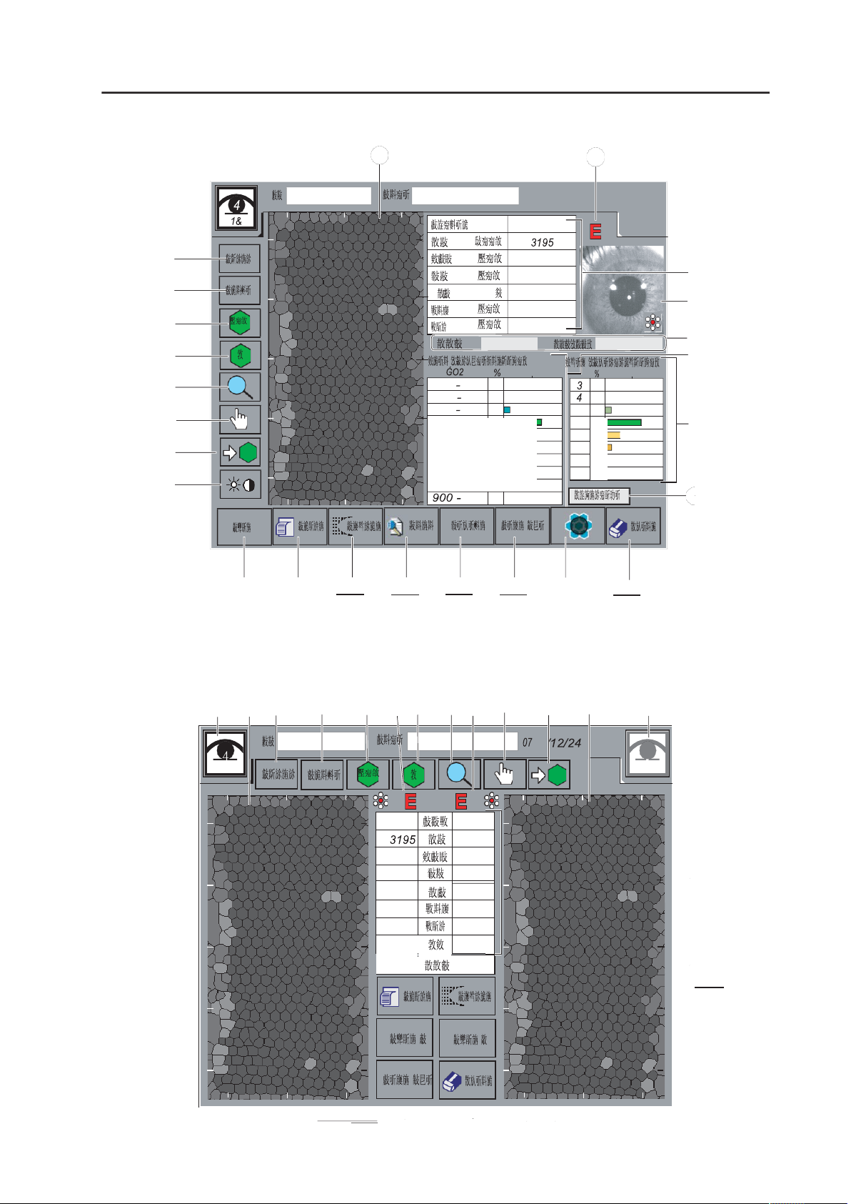
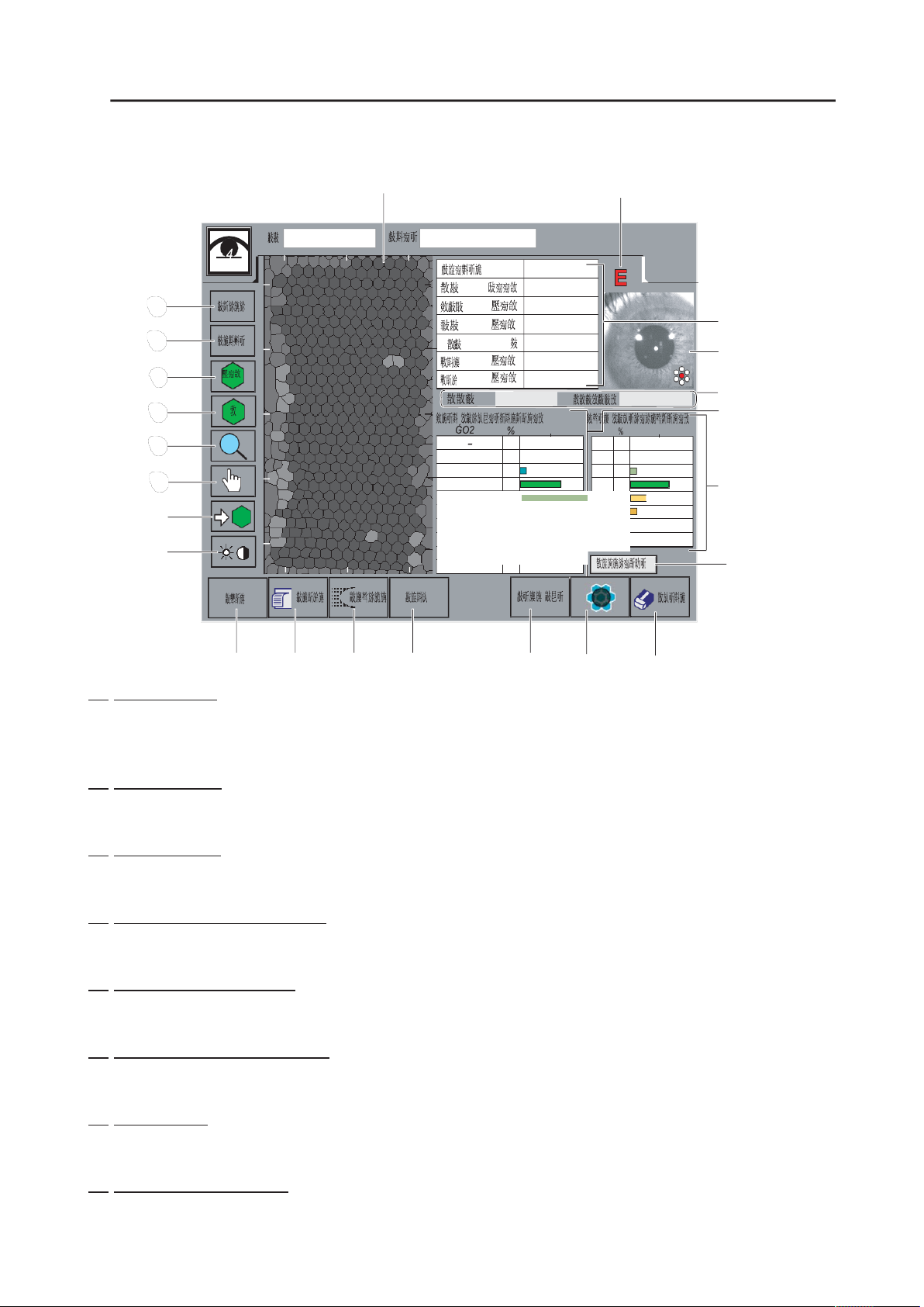
<Analytical result screen: Standard mode>
0 100
200
(14)
(15)
(16)
(17)
<Analytical result screen: Standard mode>
(25)
(1) (2)
(3)
(4)
(22)(5) (6)(22) (7) (8)
(18)
(19)
(26)
(1)
(20)
(25)
(10)
(21)
(15) (14)
(19)
(20)
(14) (16)

2-9
07/12/24 24:00
(2)
(3)
(4)
(5)
(6)
(7)
(8)
(9)
325
3195
313
94
30
420
205
(10)
(23)
520 㱘㫄
200 - 300
400 - 500
20
7 20
(21)
(11)
(12)
900 -
(13)
533 㱘㫄
1&
500 - 600
10 8
10
600 - 700
9
700 - 800
10-
800 - 900
<Analytical result Screen: Display of both eyes in Quick mode>
(1) Image display
(14) (15)
(1)
0 100
100 - 200
300 - 400 60
(16) (24) (19)
(22)
10
(26)
3
4
5 10
6# 60
(20)
Displays the image.
(2) “Photo” button
Displays the raw endothelial image.
(3) “Trace” button
Displays the extracted edges.
(4) Display by dimension button
According to the analysis result, each cell dimension is color coded and displayed.
(5) Display by shape button
According to the analysis result, each shape is color coded and displayed.
(6) Enlarge and Reduce buttons
Enlarges or reduces the size of the displayed image.
(7) Move button
Moves the displayed area on the screen when the image is enlarged.
(8) Select/Disabling button
Selects or disables the cells to be used for analytical calculation.
 Loading...