

Roda RF-DT-20-02-L-M, RF-DT-30-02-L-M, RF-DT-35-02-L-M, RF-DT-45-02-L-M, RF-DT-55-02-L-M User guide
...Page 1
FAN COIL DUCT TYPE
ENGINEERING
INSTALLATION AND OPERATION MANUAL
RF-DT-20-02-L-M
RF-DT-30-02-L-M
RF-DT-35-02-L-M
RF-DT-45-02-L-M
RF-DT-55-02-L-M
RF-DT-70-02-L-M
RF-DT-90-02-L-M
RF-DT-110-02-L-M
Page 2
CONTENTS PAGE
TECHNICAL CHARACTERISTICS UNIT STANDARD
SPECIFICATION
COIL DATA
COOLING PERFORMANCE
HEATING PERFORMANCE
THERMOSTAT
THREE-WAY MOTORIZED VALVES
DIMENSIONS
INSTALLATION
MAINTENANCE
3
5
6
6
9
13
15
17
18
19
Page 3
TECHNICAL CHARACTERISTICS UNIT STANDARD
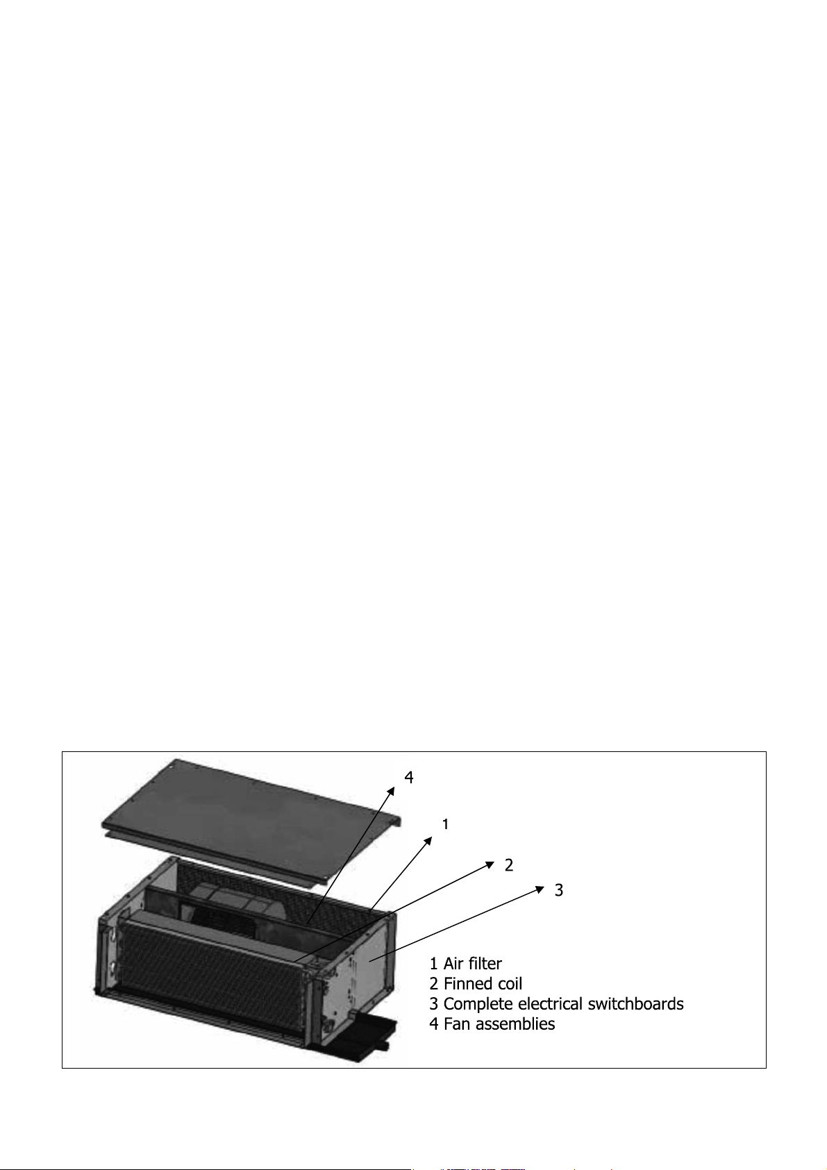
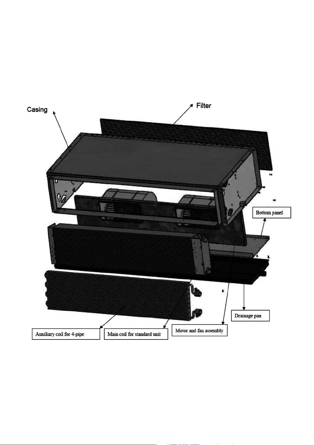
BEARING STRUCTURE
Bearing structure made of large thickness galvanized sheet-steel with holes for fixing to wall/ceiling + Thermalacoustic internal insulation
CABINET
Cabinet made of thick steel-sheet to make it resistant to rust, corrosion, chemical agents, solvents, aliphatic and
alcohols. The cabinet is with thermo acoustic internal insulation and holes to hang unit.
AIR DELIVERY GRILL
Air delivery grill by fixed finis, adjustable on two positions (air flow can be reversed by rotating grill by 180°). Made of
gray ABS (similar to RAL7035), supplied with small side doors for easy access to control planet.
HEAT EXCHANGER
Highly efficient coil which copper pipes and aluminum fins fixed by mechanical expansion. Coil connections provided
with anti torsion system, hand air vent valves, hand water drain valves.
Coils tested at the pressure of 30 bar, intended to work with water at 15 bar pressure.
FAN SECTION
Fan section including 1 or 2 centrifugals fans with double air inlet metal blades (forward curved fins) directly coupled to
the electric motor. Fan section statically and dynamically balanced. Extensive diameter fans (= high air flow and high
static pressure) and few revolutions (= low noise level). Electric motor has
3 speeds, provided with heat protection (Xlixon), running capacitor permanently switched on, Class B, electric cables
protected by double insulation. Fan section is easy to remove.
AIR FILTER
Air filter easy to remove, made of a metal frame holding filtering section which can be regenerated by water wash,
blowing, suction.
DRAIN PAN
Drain pan with drain pipe Ø 21mm (standard on the same side of coil connections) and heat insulation
SWITCHBOARD
The unit is supplied equipped with connection terminal board for the ventilation speeds.
.3.
Page 4
.4.
Page 5
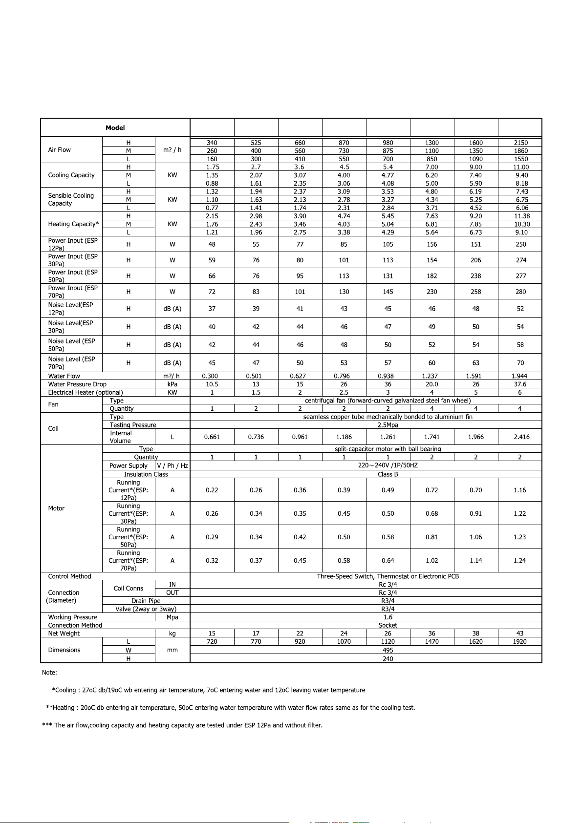
RF - DT SERIES SPECIFICATIONS:
RF- -20-02-L-MDT RF- -30-02-L-MDT RF- -35-02-L-MDT RF- -45-02-L-MDT RF- -55-02-L-MDT RF- -70-02-L-MDT RF- -90-02-L-MDT
RF- -110-02-L-MDT
.5.
Page 6
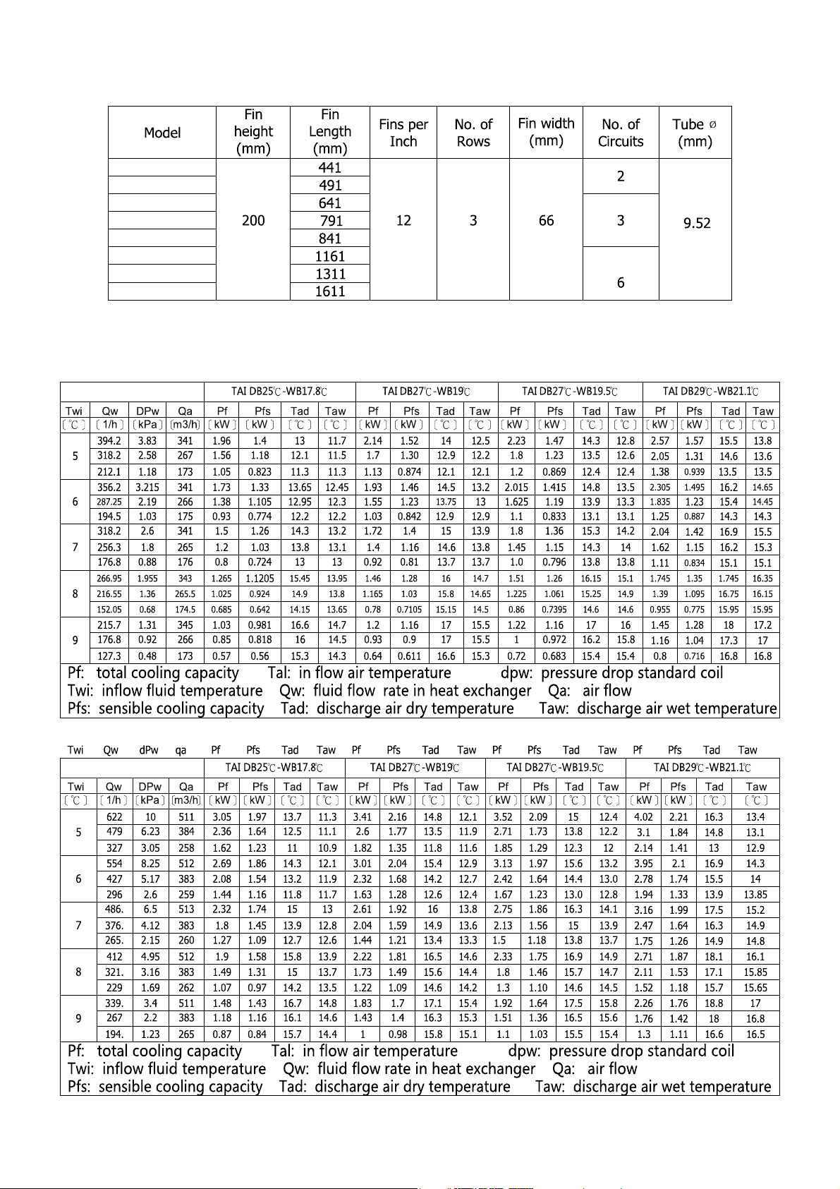
RF- -20-02-L-MDT
COIL DATA (2 PIPE 3 ROW)
RF- -30-02-L-MDT
RF- -35-02-L-MDT
RF- -45-02-L-MDT
RF- -55-02-L-MDT
RF- -70-02-L-MDT
RF- -90-02-L-MDT
RF- -110-02-L-MDT
COOLING PERFORMANCE (2 PIPE 3 ROWS)
RF- -30-02-L-MDT
.6.
Page 7
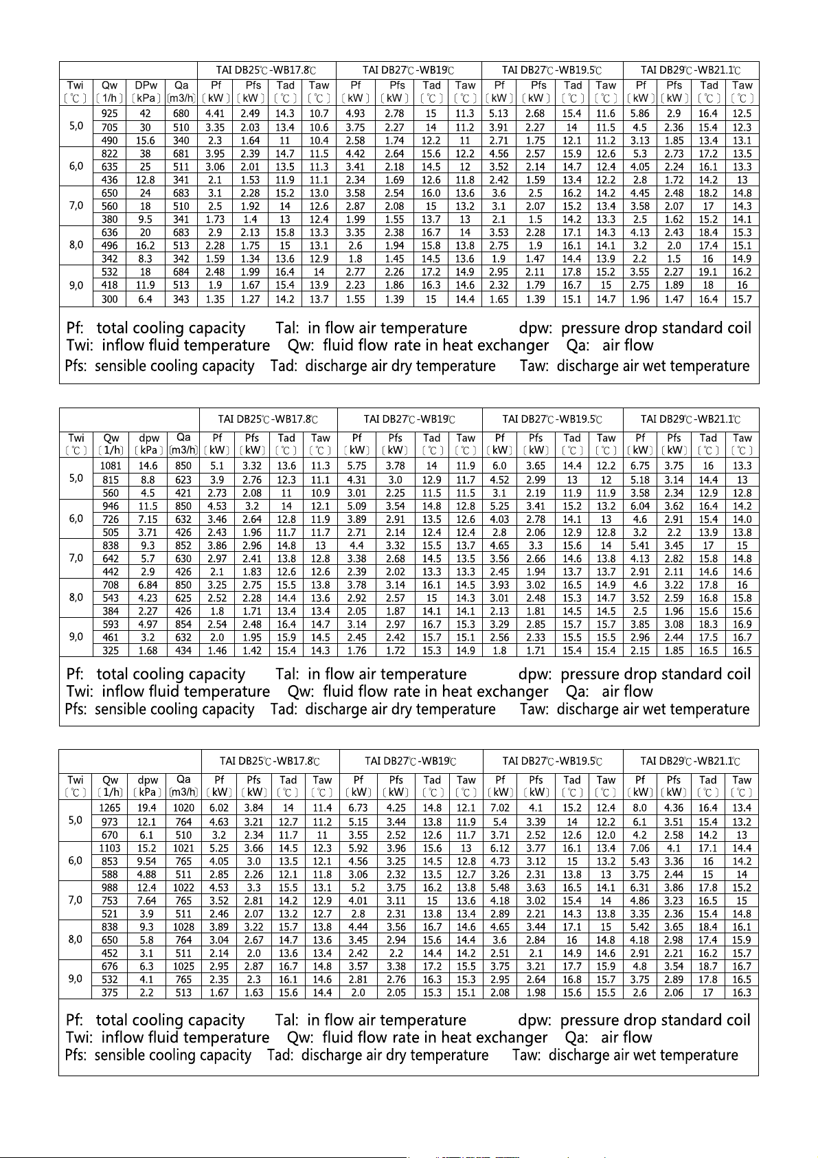
RF- -35-02-L-MDT
RF- -45-02-L-MDT
RF- -55-02-L-MDT
.7.
Page 8
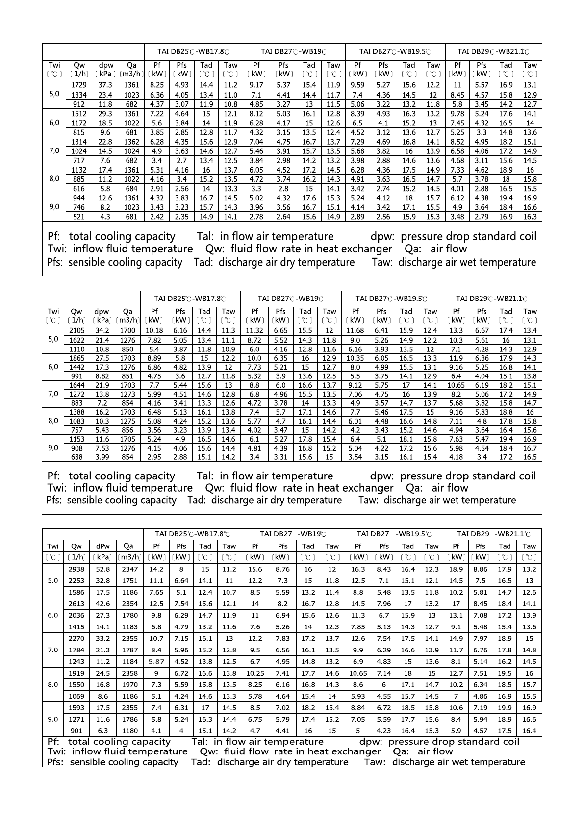
RF- -70-02-L-MDT
RF- -90-02-L-MDT
RF- -90-02-L-MDT
.8.
Page 9
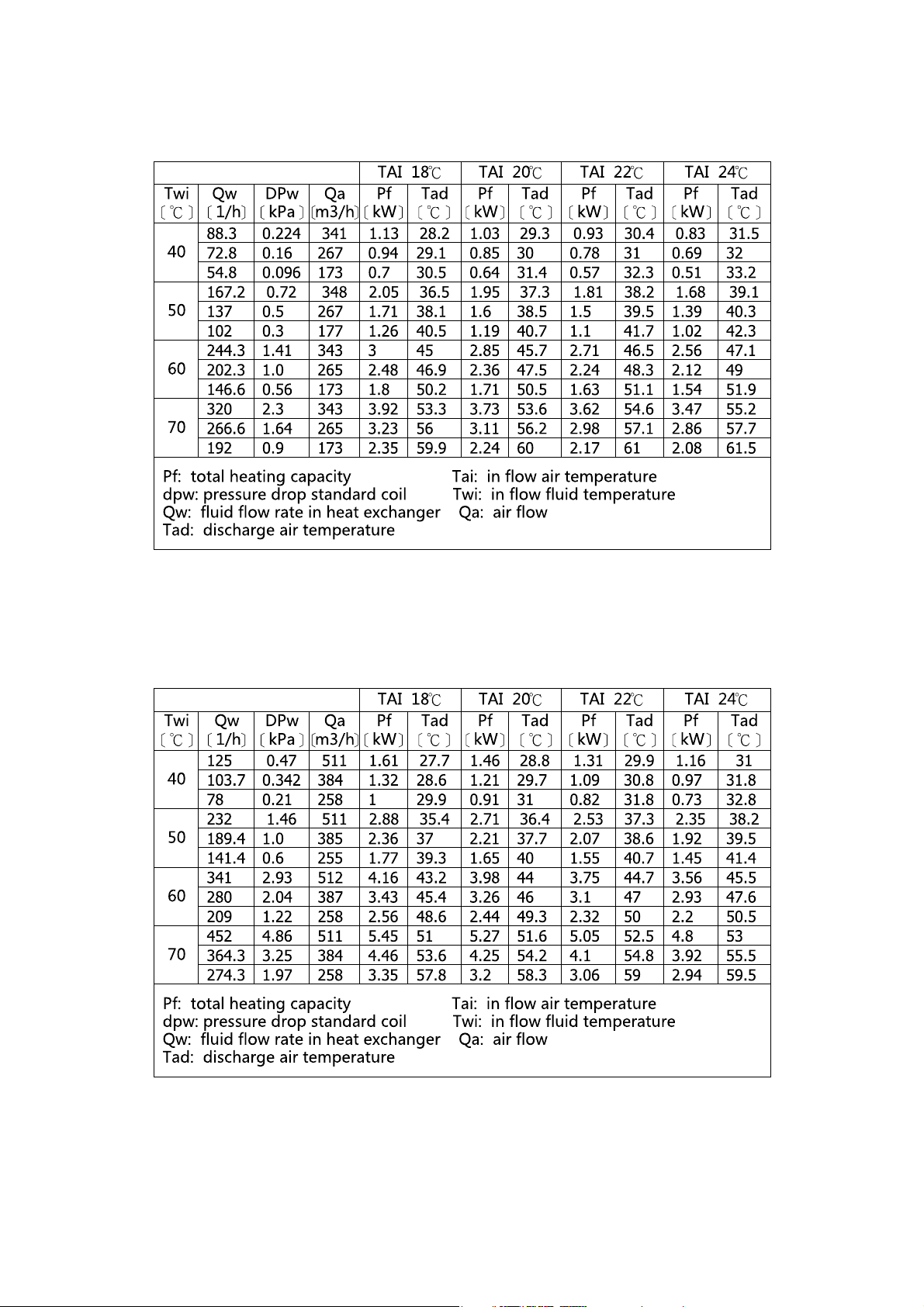
RF- -20-02-L-MDT
HEATING PERFORMANCE (2 PIPE 3 ROWS)
RF- -30-02-L-MDT
.9.
Page 10
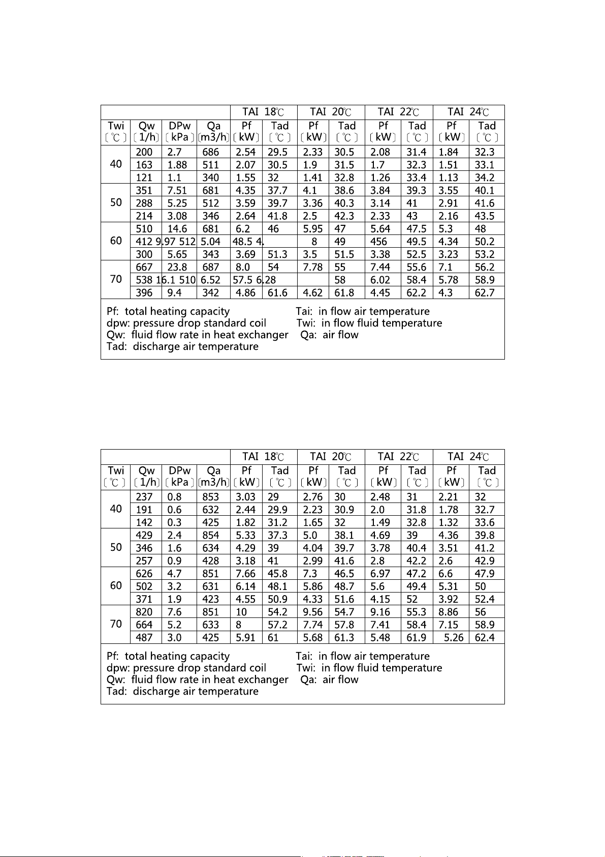
RF- -35-02-L-MDT
RF- -45-02-L-MDT
.10.
Page 11
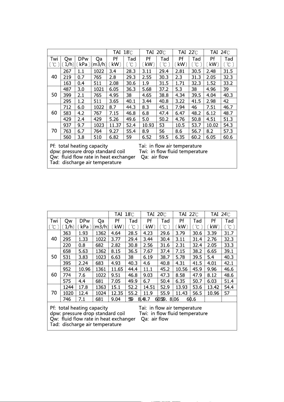
RF- -55-02-L-MDT
RF- -70-02-L-MDT
.11.
Page 12
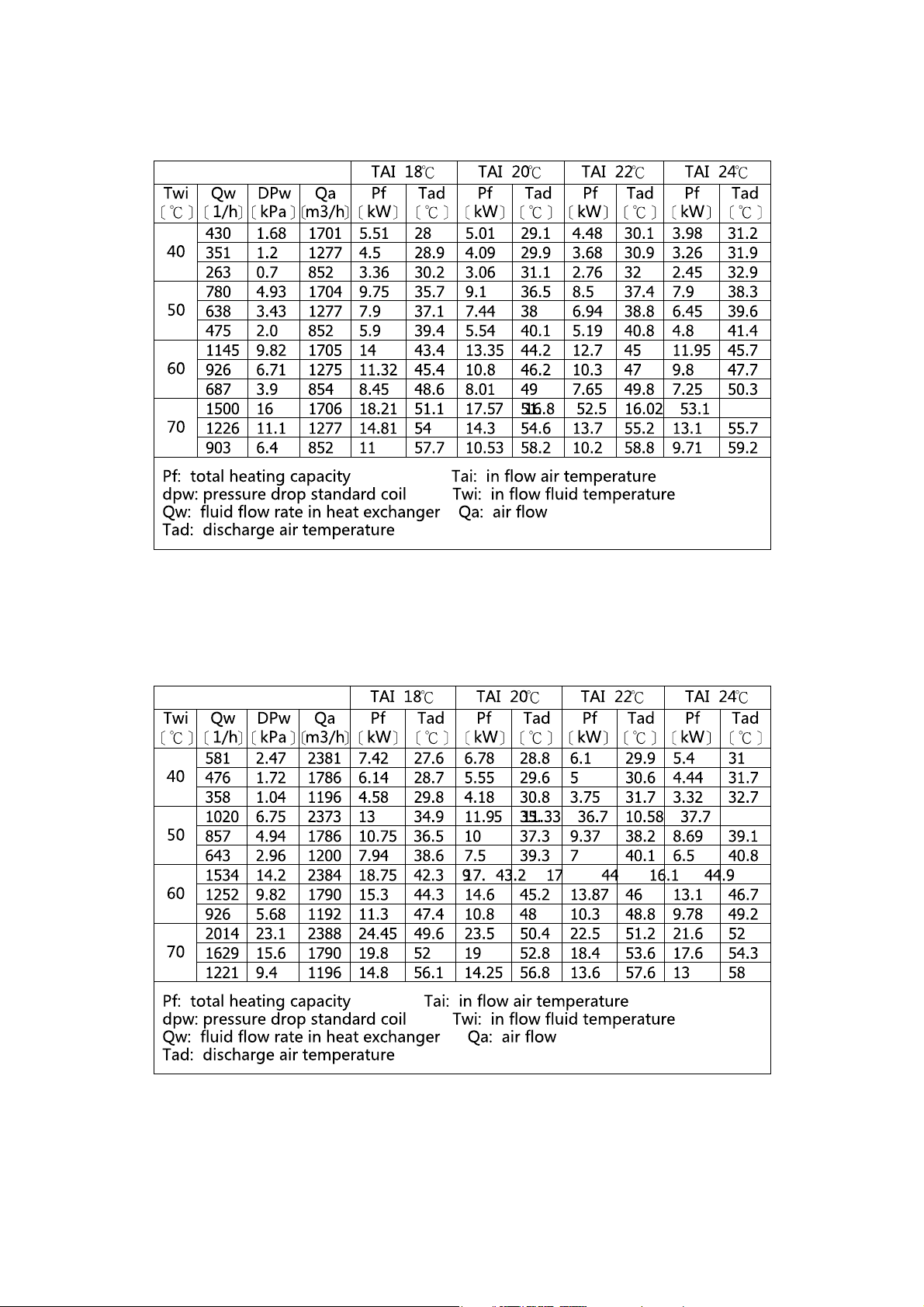
RF- -90-02-L-MDT
RF- -110-02-L-MDT
.12.
Page 13
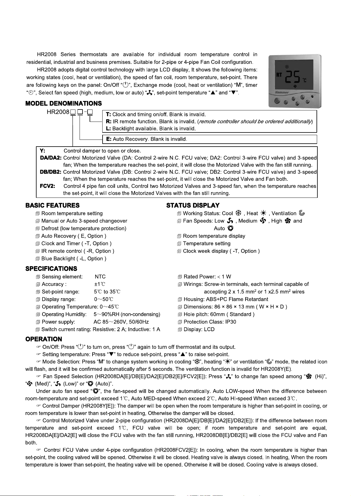
THERMOSTAT
.13.
Page 14
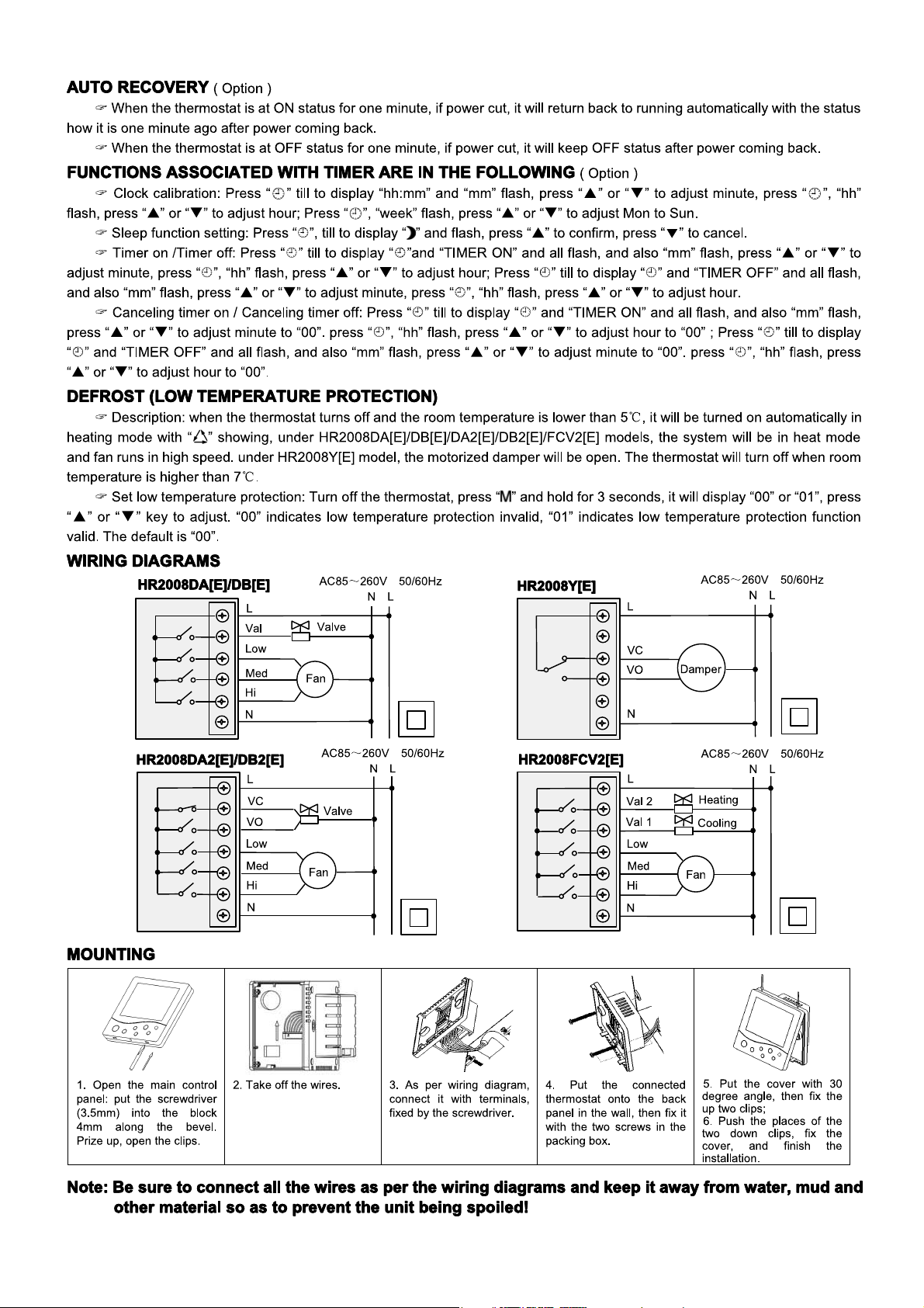
.14.
Page 15
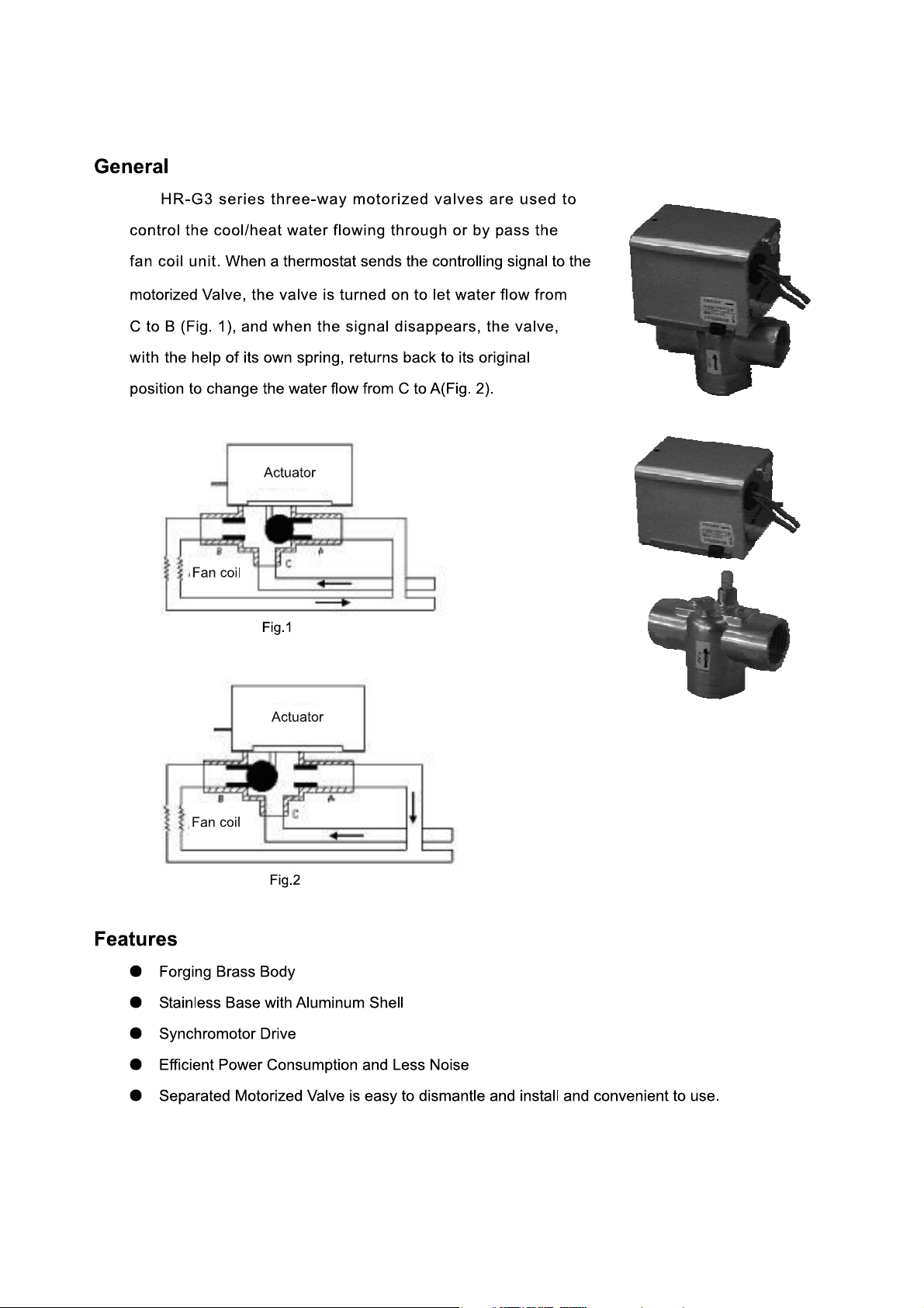
HR-G3 SERIES THREE-WAY MOTORIZED VALVES
.15.
Page 16
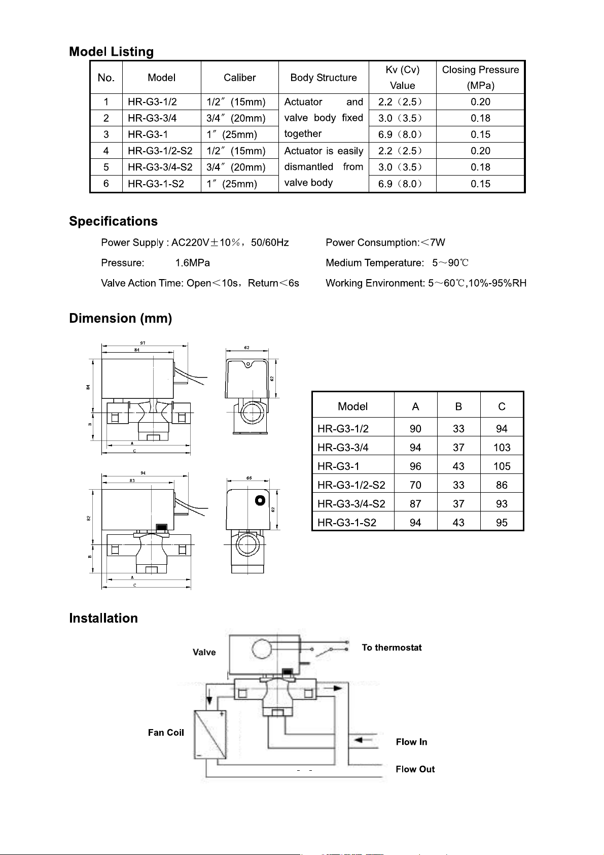
.16.
Page 17
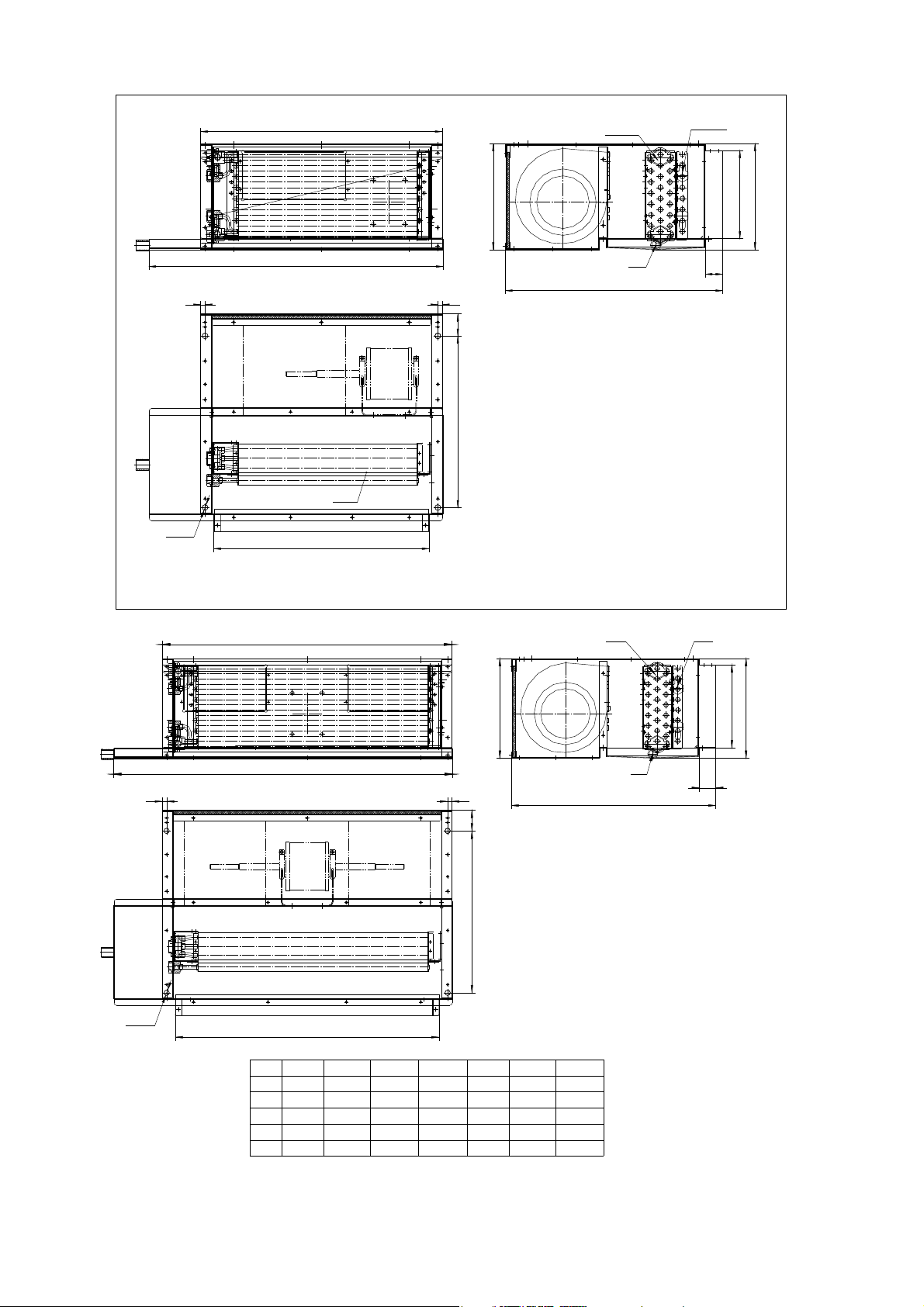
DIMENSIONS
598
720
10 10
10
4-ф13
540
50
390
240
RF- -20-02-L-MDT
2- "Rp3/4
ф25
495
2- 1 2"Rp /
200
240
40
A
C
10 10
4-ф13
MODEL
B
-30- -35- -45- -55- -70- -90- -110-
648
590
770
798
740
920
Rp3/4"
Rp1/2"
A
B
C
Rp3/4"
D
Rp1/2"
d
948
890
1070
Rp3/4"
Rp1/2"
998
940
1120
Rp3/4"
Rp1/2"
50
390
Rp3/4"
Rp1/2"
1348
1290
1470
240
1498
1440
1620
Rp3/4"
Rp1/2"
2-D 2-d
495
1798
1740
1920
Rp3/4"
Rp1/2"
ф25
200
240
40
.17.
Page 18
INSTALLATION
1) LOCATION
Before installation and running the unit, please check the following:
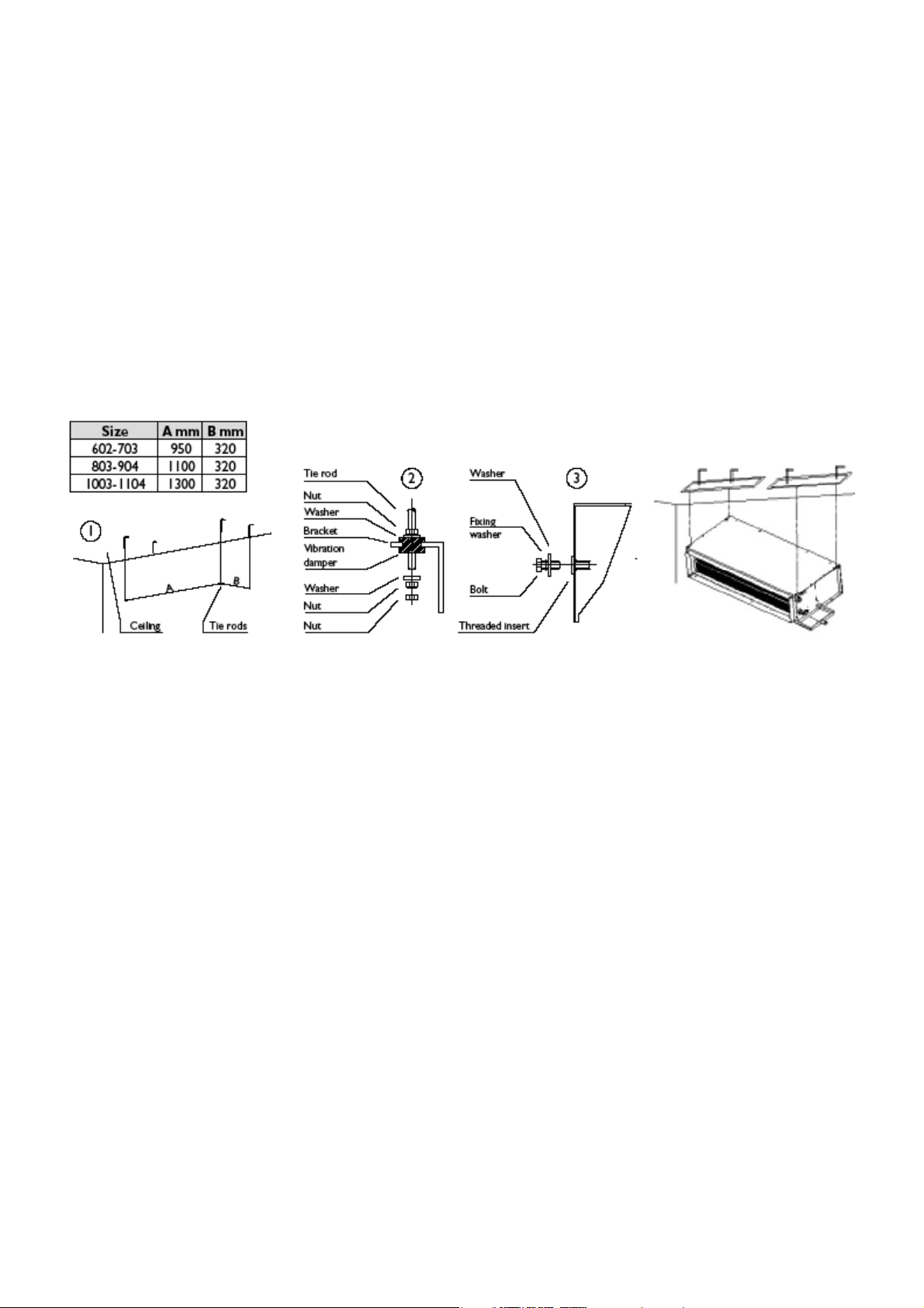
I. There must be enough space for the unit installation and maintenance. Please refer to Figure 1 for the unit's
outlines and dimensions and Figure 2 for the minimum distance between the unit and the obstacle.
ii. Please ensure enough space for piping connection and electrical wiring.
iii. Check whether the hanging rods can support weight of the unit (see specification table for weight of the unit).
iv. The unit must be installed horizontally to ensure proper operation and condensate draining.
v. The external static pressure of the ducting must be within the design static pressure range.
vi. Confirm that the unit has been switched OFF before installing or servicing the unit.
2) UNIT INSTALLATION
I. The unit is designed to be installed in a concealed ceiling. Installation and maintenance should be performed by
qualified persons who are familiar with local codes and regulations, and experienced with this type of appliance.
ii. Please refer to picture below illustrates the installation procedure.
CAUTION:
Make sure the top of the unit is level after installation. The drain pan is designed with a little gradient to facilitate
drainage.
4) PIPE CONNECTIONS
Make sure the diameter of the water pipes is adequate for the actual length of the piping and in any case not less
than the diameter of the connection on the unit. When connecting the water pipes to the coil, take care not to
damage the coil manifold. During this operation, hold the coil connections firm with a spanner to avoid damaging
them.
The fittings are located on the back of the unit looking at the air outlets.
CONNECTING THE WATER PIPING
This operation must be carried out with particular care. The unit is fitted with a gravity drainage condensate drain
pan with an open connection on the back of the unit. The pipe should have an internal diameter of at least 16 mm.
The drain connection has an external diameter of 18 mm.
Proceed according to the following instructions (see figure).
1. Connect the condensate drain hose to the pan outlet with a hose clip.
2. Make sure the drain pipe has a slope of at least 2 cm/m without obstructions or bottlenecks.
3. Fit a siphon. By eliminating the pressure drop caused by the fan, this prevents air being sucked up by the drain
hose.
4. Connect the condensate drain pipe to a rainwater drainage system. Do not connect to the sewage system as
odors may be sucked up if the water in the siphon evaporates.
5. After connecting, check correct drainage of the condensate by pouring water into the pan.
.18.
Page 19
MAINTENANCE
GENERAL
1. Installation and maintenance should be performed by qualified persons who are familiar with local codes
and regulations, and experienced with this type of appliance.
2. Confirm that the unit has been switched OFF before installing or servicing the unit.
3. A good general maintenance plan will avoid losses and unexpected shutting down of the equipment.
4. Dirty filters reduce air flow as well as unit performance. Thus changing or cleaning the filters is very important.
Check the cleanliness of filter and replace or clean as required monthly.
5. Coils should be cleaned from dust, dirt or lint with compressed air or water. They can be brushed with a soft
brush and vacuum cleaner.
6. Water coil not used during winter season should be drained, or anti-freezing solution should be added to the
water circuit to avoid freezing.
7. Monthly:
a. Inspect and clean condensate drain pan to avoiding clogging of drainage by dirt, dust, etc. Inspect drainage
piping to ensure the proper condensate flow.
b. Check and clean the coil. Clean the coils with low pressure water jet or low pressure air.
c. Clean and tighten all the wiring connections.
d. Drain out the system water and check for build up of mineral deposits.
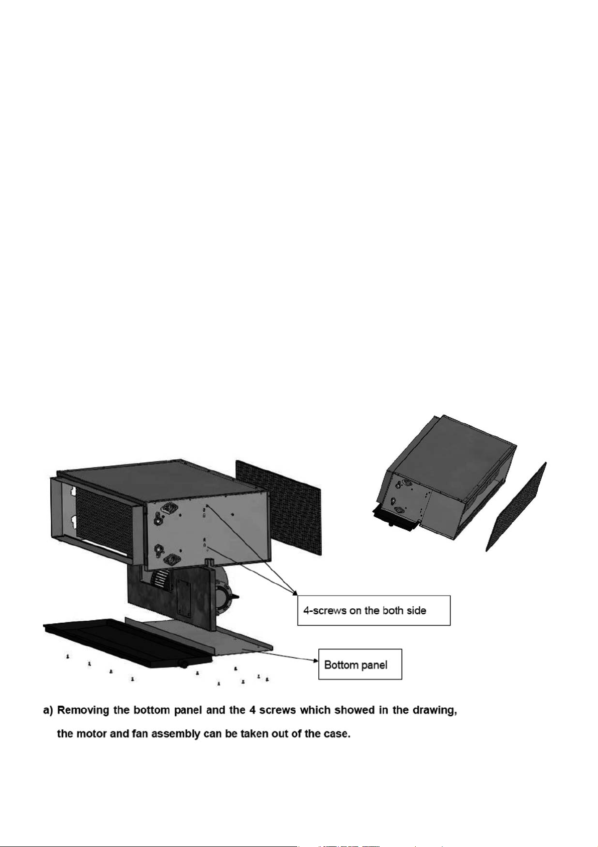
FILTER CLEANING
1. Loosen the screws and remove the filter from the bottom.
2. Clean the filter with a brush, or with water.
3. Put back the filter by sliding it back into the groove.
4. Re-tighten the filter side plate with screws.
.19.
Page 20

 Loading...