

Page 1

0
power your future℠
ROCFORCE
BATTERYBANKINSTALLATIONS
User Manual
1
Table of Contents
Chapter 1. Important Safety Instructions .............................................................2
Chapter 2. Introduction to the Rear Panel ...........................................................4
2.1. Rear Panel Descriptions ....................................................................4
Chapter 3. Installation and Operation..................................................................5
3.1. Unpacking ..........................................................................................5
3.2. Selecting Installation Position ............................................................6
3.3. Installation of Casters Cover and Rack/Tower kits............................6
3.4. Installation Instructions.......................................................................7
3.5. Battery Replacement..........................................................................9
3.6. Storage Instruction.......................................................................... 13
Page 2

2
Chapter 1. Important Safety Instructions
SAVE THESE INSTRUCTIONS
This manual contains important instructions that should be followed during
installation and maintenance of the battery bank and batteries.
An Important Notice
• This battery bank is connected to an UPS. There will be over 240 DC voltage at the
output terminals if the UPS or DC breaker is turned on.
• Do not try to repair the unit yourself, contact your local supplier or your warranty will be
void.
• To eliminate any overheating of the battery bank, keep all ventilation openings free from
obstruction and do not place any foreign objects on top of the battery bank. Keep the
battery bank 20 cm away from the wall.
• Make sure the battery bank is installed within the proper environment as specified.
(0-40°C and 30-90% non-condensing humidity)
• Do not install the battery bank under direct sunlight. Your warranty will be void if the
batteries fail due to overheating.
• This battery bank is designed for indoor use only.
• This battery bank is not designed for use in dusty, corrosive and salty environment .
• The warranty for this battery bank will be void if water or other liquid is spilt or poured
directly onto the
battery bank. Similarly we do not warrant any damage to the battery
bank if foreign objects are deliberately or accidentally inserted into the battery bank
enclosure.
• The battery will discharge naturally if the system is unused for a period of time.
• It should be recharged every 2-3 months if unused. If this is not done, then the
warranty will be null and void. During normal operation, the batteries will be
automatically remained in charged condition.
3
• Servicing of Batteries Should be Performed or Supervised by Trained Personnel with
Knowledge of Batteries and the Required Precautions
• When Replacing Batteries, Replace With the Same Quantity, Type & Capacity.
• CAUTION – Do Not Dispose of Battery or Batteries in an open fire. The Battery May
Explode.
• CAUTION – Do not open or mutilate the batteries. The electrolyte from the batteries is
toxic and harmful to the skin and eyes.
• CAUTION – Risk of Electric Shock – Battery Circuit is not isolated from AC, hazardous
Voltage may exist between battery terminals and ground. Test before touching with
bare hands.
• CAUTION – A Battery can present a Risk of Electrical Shock and High Short Circuit
Current. The Following Precaution Should be Observed When Working on Batteries:
A. Remove watches, rings, or other metal objects.
B. Use tools with insulated handles.
C. Wear rubber gloves and boots.
D. Do not lay tools or metal parts on top of batteries.
E. Disconnect charging source prior to connecting or disconnecting battery terminals.
Page 3
4
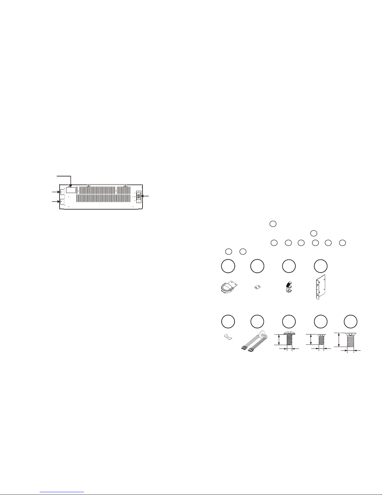
Chapter 2. Introduction to the Rear Panel
2.1. Rear Panel Descriptions
ToUPSBattery
ToExtendedBattery
G
+
G
+
DCBreaker
30
A
250Vdc
DC Breaker
UPS connector
Battery/Charger
connector
Electric spec.
5
Chapter 3. Installation and Operation
Note: The packing condition and the external outlook of the unit should be
inspected carefully before installation. Retain the packing material for future use.
3.1. Unpacking
3.1.1. Take the battery bank out of the PE foam.
3.1.2. Remove the packing materials.
Note: The battery bank module is approx. 120 kgs, be cautious when
unpacking and lifting the unit to avoid injury.
.
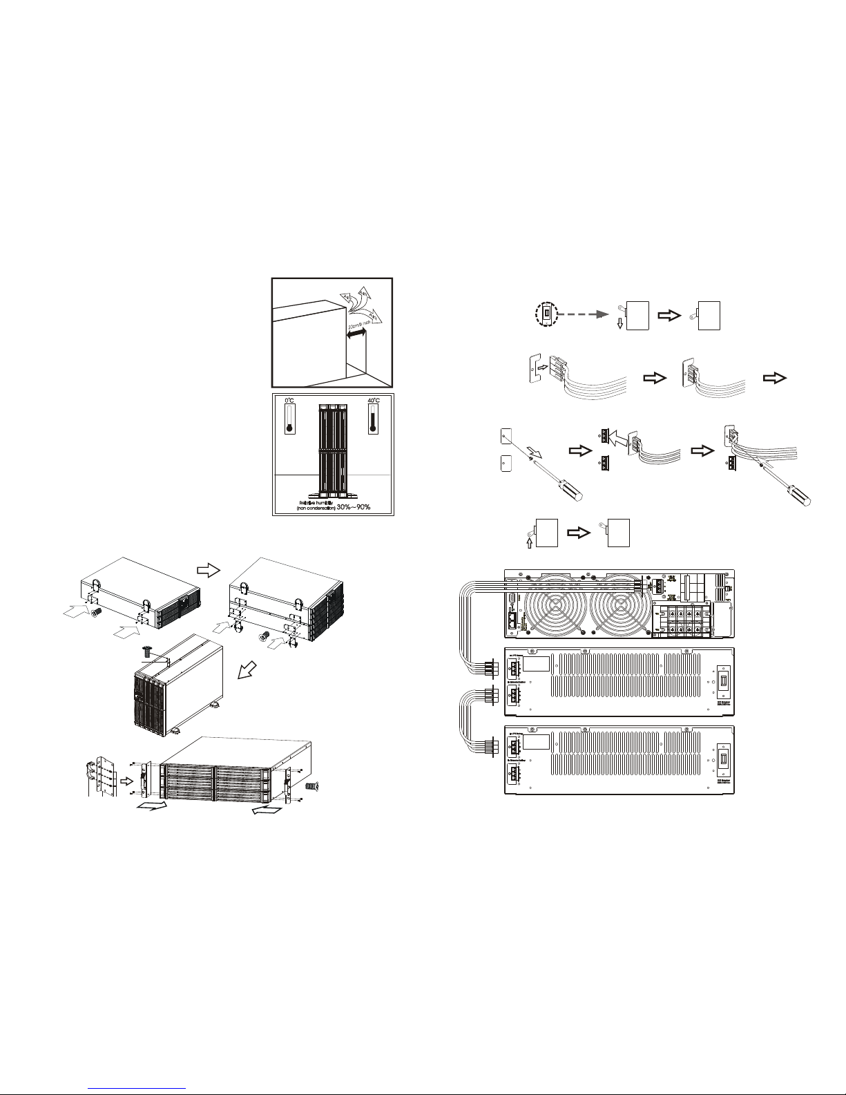
3.1.3. Standard Package includes:
3.1.3.1. User's Manual
3.1.3.2. DC connect cable().
3.1.3.3. A pair of kits to fix DC connect cable( ).
3.1.3.4. The Rack/Tower kits ~ , ~ , ~ and
~ for RT model.
B2B1
S3S1
C2 C1A2A1
C1
C2
C1 C2
S2 S3
x8 x6
6.0±1.0mm
M3
8.0±1.0mm
M4
A1 A2
x4 x1
B1
B2
x2
x2
S1
x2
6.0±1.0mm
M3
x2
x1
Page 4
6
3.2. Selecting Installation Position
It is necessary to select a proper environment to
install the unit, in order to minimize the possibility of
damage to the battery bank and extend the life of the
batteries. Please follow the instructions below:
3.2.1. Keep at least 20cm(8 inches) clearance from
the rear panel of the battery bank from the
wall or other obstructions.
3.2.2. Do not block the air-flow to the ventilation
openings of the unit.
3.2.3. Please ensure the installation site
environmental conditions are in accordance
with the battery bank working specifications
to avoid overheat and excessive moisture.
3.2.4. Do not place the battery bank in a dusty or
corrosive environment or near any
flammable objects.
3.2.5. This battery bank is not designed for outdoor
use.
3.3. Installation of Casters Cover and Rack/Tower kits
B1B2S3
S2
S2
A1
A1
S1
A2
S2
7
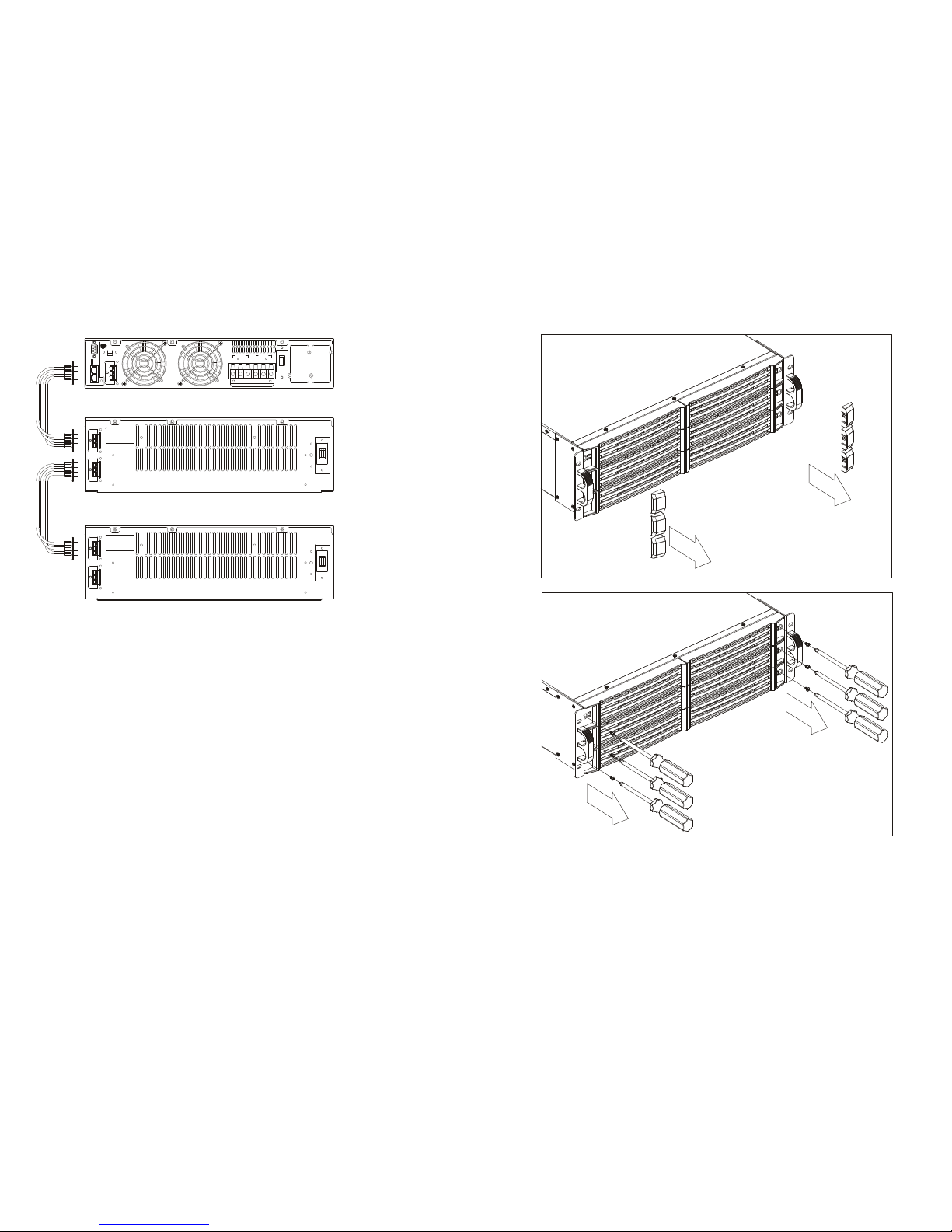
3.4. Installation Instructions
C1
OFF ON
Step 1
ON OFF
Step 2
Step 3
C2
Step 4
UPS
First Battery Bank
Second Battery Bank
Page 5
8
To UPS Battery
To Extended Battery
G
+
G
+
DC Breaker
30A 250Vdc
L12N1G1L21N22G2
OUTPUT INPUT
ON
OFF
S1
Ext. Battery
+
-
G
ParallelWorkComm.
TNVCommunicationNetwork
BusNotIntendedto
EPO
RS232
CB 1
Utilit
y
Input
Breaker
To UPS Battery
To Extended Battery
G
+
G
+
DC Breaker
30A 250Vdc
UPS
First Battery Bank
Second Battery Bank
9
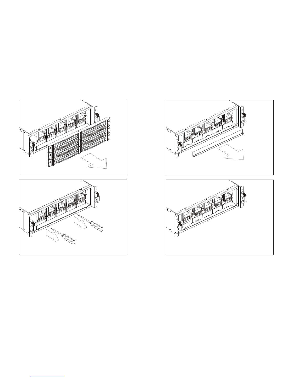
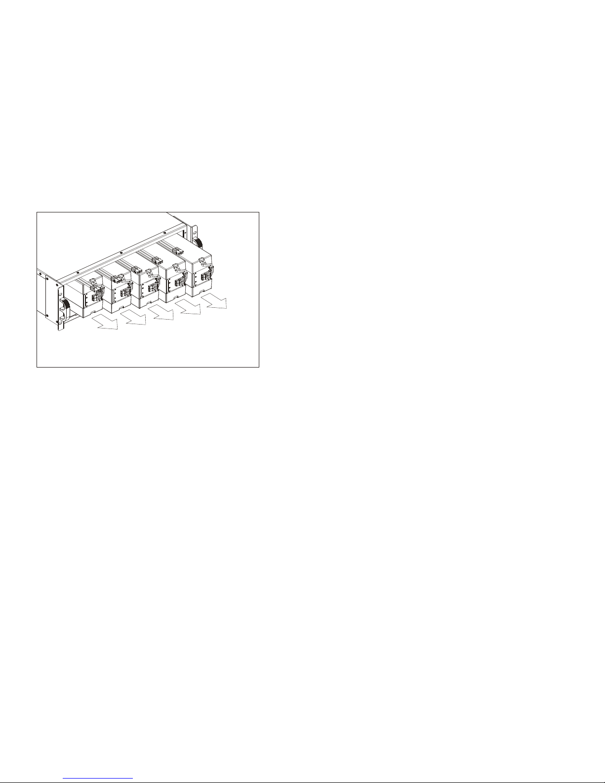
3.5. Battery Replacement
Step 1
Step 2
Page 6
10
Step 3
Step 4
11
Step 5
Step 6
Page 7
12
Step 7
13
3.6. Storage Instruction
For extended storage through moderate climate(-15 to +30 °C / +5 to +86 °F), the
batteries should be charged for 12 hours every 6 months by plugging the UPS
power cord into the wall receptacle. Repeat this every 3 months under high
temperature (+30 to +45 °C / +86 to +113 °F) environment.
Page 8

14
15
192321752028000
 Loading...