

Page 1

PLC-5 DeviceNet
Scanner Module
1771-SDN
User Manual
Page 2
Important User Information
Because of the variety of uses for the products described in this
publication, those responsible for the application and use of this control
equipment must satisfy themselves that all necessary steps have been
taken to assure that each application and use meets all performance and
safety requirements, including any applicable laws, regulations, codes and
standards.
The illustrations, charts, sample programs and layout examples shown in
this guide are intended solely for purposes of example. Since there are
many variables and requirements associated with any particular
installation, Allen-Bradley does not assume responsibility or liability (to
include intellectual property liability) for actual use based upon the
examples shown in this publication.
Allen-Bradley publication SGI-1.1, Safety Guidelines for the Application,
Installation and Maintenance of Solid-State Control (available from your
local Allen-Bradley office), describes some important differences between
solid-state equipment and electromechanical devices that should be taken
into consideration when applying products such as those described in this
publication.
Reproduction of the contents of this copyrighted publication, in whole or
part, without written permission of Rockwell Automation, is prohibited.
Throughout this manual we use notes to make you aware of safety
considerations:
ATTENTION
Identifies information about practices or
circumstances that can lead to personal injury or
death, property damage or economic loss
!
Attention statements help you to:
• identify a hazard
• avoid a hazard
• recognize the consequences
IMPORTANT
Allen-Bradley, Data Highway Plus, and PLC-5 are trademarks of Rockwell Automation.
ControlNet is a trademark of ControlNet International, Ltd.
DeviceNet is a trademark of Open DeviceNet Vendor Association (ODVA), Inc.
Ethernet is a trademark of Digital Equipment Corporation, Intel, and Xerox Corporation.
RSLinx, RSLogix 5, and RSNetWorx are trademarks of Rockwell Software.
Windows 95/98 and Windows NT are trademarks of Microsoft Corporation.
Identifies information that is critical for successful
application and understanding of the product.
Page 3

European Communities (EC) Directive Compliance
If this product has the CE mark it is approved for installation within
the European Union and EEA regions. It has been designed and tested
to meet the following directives.
EMC Directive
This product is tested to meet the Council Directive 89/336/EC
Electromagnetic Compatibility (EMC) by applying the following
standards, in whole or in part, documented in a technical construction
file:
EN 50081-2 EMC — Generic Emission Standard, Part 2 —
•
Industrial Environment
EN 50082-2 EMC — Generic Immunity Standard, Part 2 —
•
Industrial Environment
This product is intended for use in an industrial environment.
Low Voltage Directive
This product is tested to meet Council Directive 73/23/EEC Low
Voltage, by applying the safety requirements of EN 61131-2
Programmable Controllers, Part 2 - Equipment Requirements and
Tests. For specific information required by EN 61131-2, see the
appropriate sections in this publication, as well as the Allen-Bradley
publication Industrial Automation Wiring and Grounding Guidelines
For Noise Immunity, publication 1770-4.1.
This equipment is classified as open equipment and must be mounted
in an enclosure during operation to provide safety protection.
Page 4

Page 5

About This User Manual
Preface
Introduction
This user manual is designed to provide you enough information to
get a small example application up and running. Use this manual if
™
you are knowledgeable about DeviceNet
may not have used the products in conjunction. The information
provided is a base; modify or expand the examples to suit your
particular needs.
The manual contains instructions on configuring a DeviceNet network
using RSLinx and RSNetWorx for DeviceNet software. It also describes
how to use the PLC-5 pass-through feature to communicate with the
DeviceNet network for adjustment and tuning of network devices via
other networks, including:
ControlNet
•
Ethernet
•
Data Highway Plus (DH+)
•
The example application demonstrates how to perform control on
DeviceNet using a PLC-5 processor and the 1771-SDN module. You
use RSLogix 5 programming software to create a ladder logic program
to control a photoeye and a RediSTATION
and PLC-5™ products, but
™
.
IMPORTANT
1 Publication 1771-6.5.132 - June 2000
This User manual should be used in conjunction
with the 1771-SDN DeviceNet Scanner Module
Installation Instructions, publication 1771-5.14. The
Installation Instructions contain important
information on configuring your scanner.
Page 6
P-2 About This User Manual
Contents
This user manual contains the following chapters:
Before You Begin
1
go to Chapter 1
2
Planning Your
Configuration
go to Chapter 2
Setting Up the
3
Hardware
go to Chapter 3
Troubleshooting
7
go to Chapter 7
Configuring the
4
DeviceNet Network
go to Chapter 4
Configuring DeviceNet
5
From Another Network
go to Chapter 5
6
Creating and Running
the Application Program
go to Chapter 6
Audience
This manual is intended for control engineers and technicians who are
installing, programming, and maintaining a control system that
includes a PLC-5 processor communicating on a DeviceNet network
through a 1771-SDN module.
We assume that you:
are developing a DeviceNet network using a PLC-5 processor in
•
conjunction with the 1771–SDN scanner module
• know each of your device’s I/O parameters and requirements
• understand PLC-5 processor programming and operation
®
• are experienced with the Microsoft
• are familiar with RSNetWorx for DeviceNet software
Windows™ environment
Publication 1771-6.5.132 - June 2000
Page 7

About This User Manual P-3
The Example Application
Product Name Catalog Number Series Revision
Qty Hardware
1
PLC-5C processor
1 1771 Universal I/O chassis 1771-A1B, -A2B, -A3B, -A3B1,
1 DeviceNet Scanner module 1771-SDN/B B -
1
Ethernet Interface module
1 DeviceNet Quad-Tap 1492-DN3TW - -
1 RediSTATION operator interface module 2705-TxDN1x42x-xxxx - -
1 Series 9000 Photoeye 42GNP-9000 or equivalent
1 DeviceNet RS-232 interface module 1770-KFD - -
1 RS-232 cables 1787-RSCABL/A (PC to 1770-KFD) - -
- DeviceNet dropline or trunkline
cables, as needed
1 24V Power Supply Regulated 24VDC, 8A - -
1 PC IBM-compatible
Software
RSLogix 5 9324-RL5300xxx - 3.22
RSNetWorx for DeviceNet 9357-DNETL3 - 2.11
(1)
(2)
RSLinx 9355-WABxxx - 2.10
The minimum requirement for the processor is that it support block transfer instructions.
A ControlNet version of the Processor is required if interfacing the DeviceNet network and a ControlNet network (see chapters 5 and 6).
Required if interfacing the DeviceNet network and an Ethernet network. See chapters 5 and 6.
This manual describes how to set up an example application. The
manual provides examples of each step of the setup, with references
to other manuals for more details.
System Components
We used the following devices and software for the example
application. For your own application, substitute your own devices to
fit your needs. The recommended configurations in this user manual
will help you set up the test system and get it working. Your eventual
configuration will depend on your application.
Note: If you use different software or fimware versions of these
products some of your screens may appear slightly different from
those shown in the example.
(1)
(2)
1785-L20C15, -L40C15, -L80C15 - -
B-
-A4B
1785-ENET - -
1787-PCABL, -TCABL, -MCABL - -
Windows 95/98, NT 4.0
Publication 1771-6.5.132 - June 2000
Page 8
P-4 About This User Manual
More
Common Techniques Used in This Manual
The following conventions are used throughout this manual:
Bulleted lists provide information, not procedural steps.
•
Numbered lists provide sequential steps.
•
Information in bold contained within text identifies menu
•
windows, or screen options, screen names and areas of the
screen, such as dialog boxes, status bars, radio buttons and
parameters.
TIP
This is a definition
box. When a word is
bold within the text
of a paragraph, a
definition box will
appear in the left
margin to further
define the text.
This symbol identifies helpful tips.
A definition box defines terms that may be
unfamiliar to you.
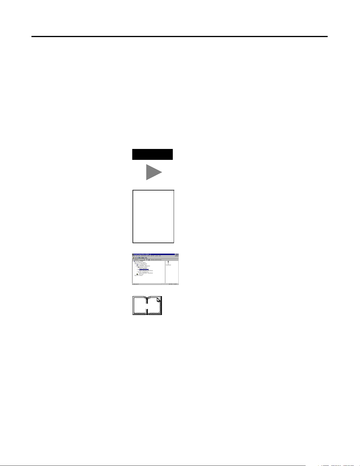
Screen captures are pictures of the software’s
actual screens. The names of screen buttons and
fields are often in bold in the text of a
procedure. Pictures of keys represent the actual
keys you press.
The “MORE” icon is placed beside any
paragraph that references sources of additional
information outside of this document.
Publication 1771-6.5.132 - June 2000
Page 9
About This User Manual P-5
Where to Find
More
Refer to the following publications as needed for additional help
when setting up and using your DeviceNet network:
More Information
For information about See this publication Publication Number
the 1771-SDN DeviceNet scanner 1771-SDN Scanner Module Installation Instructions 1771-5.14
the PLC-5 processor ControlNet PLC-5 Programmable Controllers User Manual
Phase 1.5
PLC-5 Instruction Set Reference Manual 1785-6.1
1785-PLC-5 Programmable Controllers Quick Reference 1785-7.1
the1785-ENET Ethernet interface module PLC-5 Ethernet Interface Module User Manual 1785-6.5.19
the 1771 I/O chassis Universal I/O Chassis 1771-2.210
the 1770-KFD communication module DeviceNet RS-232 Interface Module Installation Instructions 1770-5.6
a 1784-PCD communication card NetLinx DeviceNet Communication Card Installation Instructions 1784-5.29
a 1784-PCID or 1784-PCIDS card DeviceNet PCI Communication Interface Card Installation 1784-5.31
the RediSTATION RediSTATION Operator Interface User Manual 2705-804
the 9000 Series photoeye {refer to the information that came with your photoeye} n/a
DeviceNet DeviceNet System Overview DN-2.5
DeviceNet Design Manual (online) DNET-AT-001A-EN
connecting the DeviceNet network DeviceNet Cable Planning and Installation Manual DN-6.7.2
DeviceNet Cable Planning and Installation Release Note 1 DN-6.7.2-RN1
RSLinx software RSLinx Lite User’s Guide 9399-WAB32LUG
RSLogix 5 software Getting Results With RSLogix 5 9399-RL53GR
RSNetWorx for DeviceNet software DeviceNet Demo CD 9398-DNETDEMO
terms and definitions Allen-Bradley Industrial Automation Glossary AG-7.1
1785-6.5.22
TIP
TIP
Many of the above are available online from the
Automation Bookstore:
http://www.theautomationbookstore.com
.
For more information about Rockwell Software
products, visit the Rockwell Software internet site:
http://www.software.rockwell.com
.
Publication 1771-6.5.132 - June 2000
Page 10

P-6 About This User Manual
Terminology
This term Means
Bridge The scanner module’s support of explicit message transfer.
Change of State A type of I/O data communication. The scanner module can send and
receive data with slave devices that have the change of state feature. Data
is sent whenever a data change occurs. Data is updated at the rate of the
heartbeat.
Communication
The 1771-SDN scanner module or the 1770-KFD module.
Module
Cyclic A type of I/O data communication. The scanner module can send and
receive data with slave devices that have the cyclic feature. Data is only
sent at a user-configurable rate.
EDS Electronic Data Sheet. A vendor-supplied template that specifies how
information is displayed as well as what is an appropriate entry (value).
Explicit
Messaging
A type of messaging used for lower priority tasks, such as configuration
and data monitoring.
Heartbeat Rate Devices that are configured for change of state data can also send a
“heartbeat” signal to indicate proper operation.
Host Platform The computer that hosts the 1771-SDN scanner module.
I/O An abbreviation for “input and output”.
Implicit
Messaging
The type of messaging used for high priority I/O control data; e.g., change
of state, cyclic, polled, or strobed.
Input Data Data produced by a DeviceNet device and collected by the scanner module
for a host platform to read.
MAC ID The network address of a DeviceNet node.
Network The DeviceNet network or the RSNetWorx for DeviceNet software
representation of the network.
Node Hardware that is assigned a single address on the network (also referred
to as device).
Offline When the PC communication scanner is not communicating on the
network.
Online When the PC communication scanner is configured and enabled to
communicate on the network.
Output Data Data produced by a host platform that is written to the scanner module’s
memory. This data is sent by the scanner module to DeviceNet devices.
®
PC Abbreviation for an IBM
compatible personal-computer.
Polled A type of input/output-data communication. A polled message solicits a
response from a single, specified device on the network (a point-to-point
transfer of data).
Record The node address and channel-specific memory assigned in the scanner
module’s non-volatile storage for a node in the scanlist.
Rx An abbreviation for “receive”.
Scanlist The list of devices (nodes) with which the scanner is configured to
exchange I/O data.
Scanner The function of the 1771-SDN scanner module to support the exchange of
I/O with slave modules.
Slave Mode The scanner module is in slave mode when it is placed in another scanner
module’s scanlist as a slave device.
Strobed A type of I/O data communication. A strobed message solicits a response
from each strobed device (a multicast transfer). It is a 64-bit message that
contains one bit for each device on the network.
Tx An abbreviation for “transmit”.
Publication 1771-6.5.132 - June 2000
Page 11

About This User Manual P-7
Rockwell Automation Support
Rockwell Automation offers support services worldwide, with over 75
sales/support offices, 512 authorized distributors, and 260 authorized
systems integrators located throughout the United States alone, plus
Rockwell Automation representatives in every major country in the
world.
Local Product Support
Contact your local Rockwell Automation representative for:
sales and order support
•
product technical training
•
warranty support
•
support service agreements
•
Technical Product Assistance
If you need to contact Rockwell Automation for technical assistance,
call your local Rockwell Automation representative, or call Rockwell
directly at: 1 440 646-6800.
For presales support, call 1 440 646-3NET.
You can obtain technical assistance online from the following
Rockwell Automation WEB sites:
www.ab.com/mem/technotes/kbhome.html
•
www.ab.com/networks/eds
•
(electronic data sheets)
(knowledge base)
Your Questions or Comments about This Manual
If you find a problem with this manual, please notify us of it on the
enclosed Publication Problem Report (at the back of this manual).
If you have any suggestions about how we can make this manual
more useful to you, please contact us at the following address:
Rockwell Automation, Allen-Bradley Company, Inc.
Control and Information Group
Technical Communication
1 Allen-Bradley Drive
Mayfield Heights, OH 44124-6118
Publication 1771-6.5.132 - June 2000
Page 12

P-8 About This User Manual
Publication 1771-6.5.132 - June 2000
Page 13

Before You Begin
Planning Your Configuration and
Data Mapping Your Devices
Table of Contents
Chapter 1
What This Chapter Contains . . . . . . . . . . . . . . . . . . . . . . . . . . 1-1
What You Need to Know . . . . . . . . . . . . . . . . . . . . . . . . . . . . 1-1
What Your 1771-SDN Module Does . . . . . . . . . . . . . . . . . . . . 1-2
Address Density and Discrete I/O . . . . . . . . . . . . . . . . . . . . . . 1-4
Communicating with Your Devices . . . . . . . . . . . . . . . . . . . . . 1-6
Communicating with Your PLC-5 Processor. . . . . . . . . . . . . . . 1-7
What 1771-SDN Module Data Tables Are and What They Do . . 1-8
The Scanner Configuration Table (SCT) . . . . . . . . . . . . . . . 1-8
The Scanlist Table (SLT) . . . . . . . . . . . . . . . . . . . . . . . . . . 1-8
RSNetWorx Software as a Configuration Tool . . . . . . . . . . . . . 1-9
RSNetWorx for DeviceNet Configuration Screen Map . . . . 1-10
What’s Next? . . . . . . . . . . . . . . . . . . . . . . . . . . . . . . . . . . . . 1-11
Chapter 2
What You Need to Know . . . . . . . . . . . . . . . . . . . . . . . . . . . . 2-1
Beginning the Process . . . . . . . . . . . . . . . . . . . . . . . . . . . . . . 2-1
The Example Network . . . . . . . . . . . . . . . . . . . . . . . . . . . . . . 2-2
Example Network Devices . . . . . . . . . . . . . . . . . . . . . . . . 2-2
RediSTATION Operator Interface Data Mapping. . . . . . . . . 2-4
Mapping RediSTATION Input Data
for a Block Transfer Read . . . . . . . . . . . . . . . . . . . . . . . . . 2-5
Mapping RediSTATION Output Data
for a Block Transfer Write . . . . . . . . . . . . . . . . . . . . . . . . . 2-6
Photoeye Input Data Mapping. . . . . . . . . . . . . . . . . . . . . . 2-7
Mapping Photoeye Input Data for a Block Transfer Read . . 2-8
What’s Next? . . . . . . . . . . . . . . . . . . . . . . . . . . . . . . . . . . . . . 2-9
Chapter 3
Hardware Setup
i Publication 1771-6.5.132 - June 2000
What This Chapter Contains . . . . . . . . . . . . . . . . . . . . . . . . . . 3-1
Installing the 1770-KFD Interface Module . . . . . . . . . . . . . . . . 3-1
Installing the PLC-5 Processor . . . . . . . . . . . . . . . . . . . . . . . . . 3-2
Setting the I/O Chassis Backplane Switches . . . . . . . . . . . . 3-2
Going Online to the PLC-5 Processor. . . . . . . . . . . . . . . . . 3-3
Installing the 1785-ENET Ethernet Module. . . . . . . . . . . . . . . . 3-5
Installing the 1771-SDN Scanner Module . . . . . . . . . . . . . . . . . 3-7
Setting the Channel 1 Data Rate
and Node Address Switches . . . . . . . . . . . . . . . . . . . . . . . 3-8
Setting the I/O Chassis Addressing Node Switches . . . . . . . 3-8
Installing the Scanner Module in the Chassis . . . . . . . . . . . 3-9
Connecting the Scanner to the DeviceNet Network . . . . . 3-10
Installing the RediSTATION Operator Interface . . . . . . . . . . . 3-11
Installing the Series 9000 Photoeye . . . . . . . . . . . . . . . . . . . . 3-12
How Your Example System Will Look. . . . . . . . . . . . . . . . . . 3-13
What’s Next? . . . . . . . . . . . . . . . . . . . . . . . . . . . . . . . . . . . . 3-13
Page 14

Table of Contents ii
Configuring the
DeviceNet Network
Communicating with DeviceNet
from Another Network
Chapter 4
What This Chapter Contains . . . . . . . . . . . . . . . . . . . . . . . . . . 4-1
Installing the Software . . . . . . . . . . . . . . . . . . . . . . . . . . . . . . 4-1
Using RSLinx to Configure the DeviceNet Driver . . . . . . . . . . . 4-2
Using RSNetWorx for DeviceNet to Configure the Scanlist . . . . 4-4
Setting Up an Online Connection . . . . . . . . . . . . . . . . . . . 4-4
Setting the 1771-SDN Node Address . . . . . . . . . . . . . . . . . 4-6
Configuring the I/O Devices . . . . . . . . . . . . . . . . . . . . . . . 4-9
Verifying the Photoeye Configuration. . . . . . . . . . . . . 4-12
Verifying the RediSTATION Configuration . . . . . . . . . 4-13
AutoMapping the Devices into the Scanlist . . . . . . . . . 4-14
Download the Configuration to the Scanner . . . . . . . . 4-17
What’s Next? . . . . . . . . . . . . . . . . . . . . . . . . . . . . . . . . . . . . 4-17
Chapter 5
What This Chapter Contains . . . . . . . . . . . . . . . . . . . . . . . . . . 5-1
Where to Find More Information. . . . . . . . . . . . . . . . . . . . . . . 5-2
Communicating with DeviceNet from a ControlNet Network . . 5-3
Configuring the DeviceNet Pass-Through Driver. . . . . . . . . 5-3
Communicating with the DeviceNet Network. . . . . . . . . . . 5-6
Communicating with DeviceNet from an Ethernet Network. . . 5-9
Configuring the Ethernet to PLC-5 Communications Driver . 5-9
Configuring the DeviceNet Pass-Through Driver. . . . . . . . 5-12
Communicating with the DeviceNet Network. . . . . . . . . . 5-15
Communicating with DeviceNet from a DH+ Network . . . . . 5-18
Configuring the DeviceNet Pass-Through Driver. . . . . . . . 5-18
Communicating with the DeviceNet Network. . . . . . . . . . 5-21
What’s Next? . . . . . . . . . . . . . . . . . . . . . . . . . . . . . . . . . . . . 5-23
Creating and Running the Example
Application Program
Publication 1771-6.5.132 - June 2000
Chapter 6
What This Chapter Contains . . . . . . . . . . . . . . . . . . . . . . . . . . 6-1
Installing the Software . . . . . . . . . . . . . . . . . . . . . . . . . . . . . . 6-2
Creating the Example Application Program . . . . . . . . . . . . . . . 6-2
Downloading and Running the Program . . . . . . . . . . . . . . . . . 6-6
Downloading and Running the Program
via a ControlNet Network . . . . . . . . . . . . . . . . . . . . . . . . . 6-6
Testing the Example Program . . . . . . . . . . . . . . . . . . . 6-8
Downloading and Running the Program
via an Ethernet Network . . . . . . . . . . . . . . . . . . . . . . . . . . 6-9
Testing the Example Program . . . . . . . . . . . . . . . . . . 6-11
Downloading and Running the Program
via a DH+ Network. . . . . . . . . . . . . . . . . . . . . . . . . . . . . 6-12
Testing the Example Program . . . . . . . . . . . . . . . . . . 6-14
What’s Next? . . . . . . . . . . . . . . . . . . . . . . . . . . . . . . . . . . . . 6-14
Page 15

Troubleshooting
1785-ENET Module
Channel Configuration
Installing and Configuring the
ControlNet Communications
Driver
Installing and Configuring the
DH+ Communications Driver
Data Map Example
Index
Table of Contents iii
Chapter 7
What This Chapter Contains . . . . . . . . . . . . . . . . . . . . . . . . . . 7-1
Module Status Indicator . . . . . . . . . . . . . . . . . . . . . . . . . . . . . 7-1
Network Status Indicator . . . . . . . . . . . . . . . . . . . . . . . . . . . . 7-2
Node/Error Code Indicator . . . . . . . . . . . . . . . . . . . . . . . . . . . 7-2
Appendix A
Configuring the Communications Channel. . . . . . . . . . . . . . . . A-1
Appendix B
Installing the 1784-KTCX15 Communication Interface Card . . . B-1
Configuring the 1784-KTCX15 Communications Driver . . . . B-2
Appendix C
Installing the 1784-KTX Communication Interface Card . . . . . . C-1
Configuring the 1784-KTX Communications Driver . . . . . . . . . C-2
Appendix D
Example Input Mapping Scheme. . . . . . . . . . . . . . . . . . . . . . D-1
Example Characteristics. . . . . . . . . . . . . . . . . . . . . . . . . . D-1
Example Framework . . . . . . . . . . . . . . . . . . . . . . . . . . . . D-2
Input Data Table Formats . . . . . . . . . . . . . . . . . . . . . . . . D-3
Example Output Mapping Scheme . . . . . . . . . . . . . . . . . . . . D-6
Example Characteristics. . . . . . . . . . . . . . . . . . . . . . . . . . D-6
Example Framework . . . . . . . . . . . . . . . . . . . . . . . . . . . . D-6
Output Data Table Formats . . . . . . . . . . . . . . . . . . . . . . . D-7
Publication 1771-6.5.132 - June 2000
Page 16

Table of Contents iv
Publication 1771-6.5.132 - June 2000
Page 17

Before You Begin
Chapter
1
What This Chapter Contains
What You Need to Know
This chapter provides an overview of communication between a
PLC-5 processor and DeviceNet devices via a 1771-SDN module. The
data tables and the RSNetWorx for DeviceNet screens and windows
used to configure the data tables are also described.
The following table identifies what this chapter contains and where to
find specific information.
For information about See page
What You Need to Know 1-1
What Your 1771-SDN Module Does 1-2
Communicating with Your Devices 1-6
What 1771-SDN Module Data Tables Are and What They Do 1-8
The Scanner Configuration Table (SCT) 1-8
The Scanlist Table (SLT) 1-8
RSNetWorx Software as a Configuration Tool 1-9
RSNetWorx for DeviceNet Configuration Screen Map 1-10
Before configuring your 1771-SDN scanner module, you must
understand:
the data exchange between the PLC -5 processor and DeviceNet
•
devices through the 1771-SDN module
user-configurable 1771-SDN module data tables
•
• the role of RSNetWorx for DeviceNet software
1 Publication 1771-6.5.132 - June 2000
Page 18
1-2 Before You Begin
What Your 1771-SDN Module Does
1771 I/O
Chassis
PLC-5
Processor
In a typical configuration, the 1771-SDN module acts as an interface
between DeviceNet devices and the PLC-5 processor.
1771-SDN
Scanner module
Series 9000
Photoeye
DeviceNet Network
RediSTATION
1770-KFD PC
Communication
Module
FLEX I/O Rack
DeviceNet
Devices
PC with RSNetWorx
for DeviceNet software
1305 Drive
The 1771-SDN module communicates with DeviceNet devices over
the network to:
read inputs from a device
•
write outputs to a device
•
• download configuration data
• monitor a device’s operational status
The 1771-SDN module communicates with the processor in the form
of Block Transfers (BT) and/or Discrete I/O (DIO). Information
exchanged includes:
• device I/O data
• status information
• configuration data
Publication 1771-6.5.132 - June 2000
Page 19
Before You Begin 1-3
A processor to I/O DeviceNet configuration is shown in the following
figure. See the referenced chapters for more information.
Input Read by Processor (Chapter 2)
Output Write by
Processor (Chapter 2)
Input Data from
Device to SDN
(Chapter 2)
Input
Device
Processor to I/O
Configure SDN module (Chapter 4)
Mapping Table (Chapters 2 and 4)
Output Data to Devices
from SDN (Chapter 2)
DeviceNet Network
PC running
RSNetWorx
for DeviceNet
Output
Device
Publication 1771-6.5.132 - June 2000
Page 20
1-4 Before You Begin
Industrial
workstation
running RSView
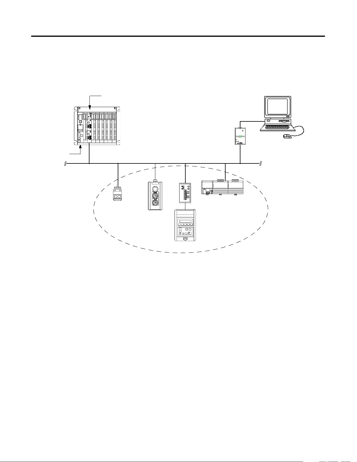
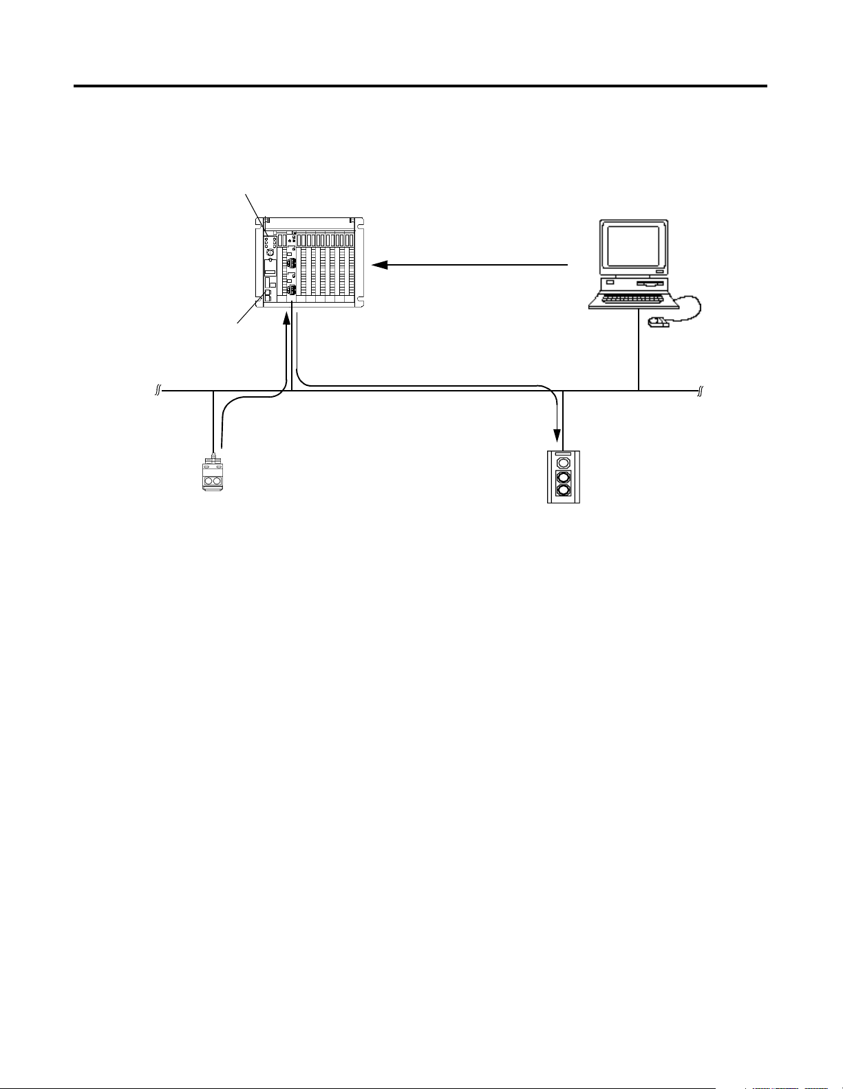
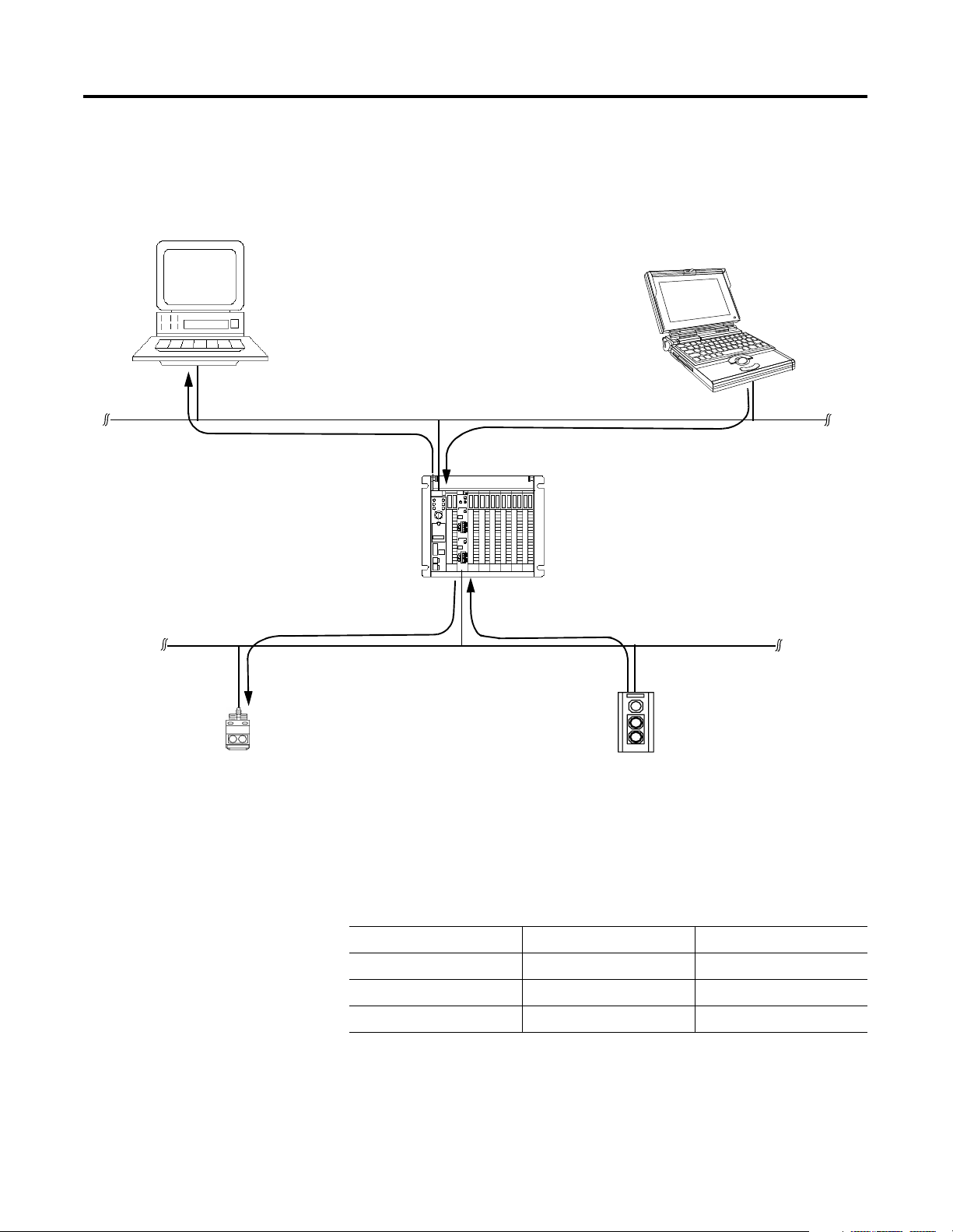
The 1771-SDN scanner module can also be used to bridge a
DeviceNet network with another network.
Configuring Devices and Data Collection on
Higher-Level Networks Via PLC-5/SDN
Laptop PC
running
RSNetWorx
ControlNet, DH+, or Ethernet Network
Target Device to
be configured
Address Density and Discrete I/O
Configuration of device
using RSNetWorx
(Chapters 4 & 5)
You can use three addressing methods with your 1771-SDN scanner
module. The number of discrete I/O bits you have available for data
transfer is affected by the addressing mode selected.
SDN scanner
module
DeviceNet Network
Addressing Mode Discrete Inputs Discrete Outputs
2-slot 0 bits 0 bits
1-slot 8 bits 8 bits
1/2-slot 24 bits 24 bits
Collection of status
or alarm data
(Chapter 6)
Source Device
to collect data
Publication 1771-6.5.132 - June 2000
Page 21
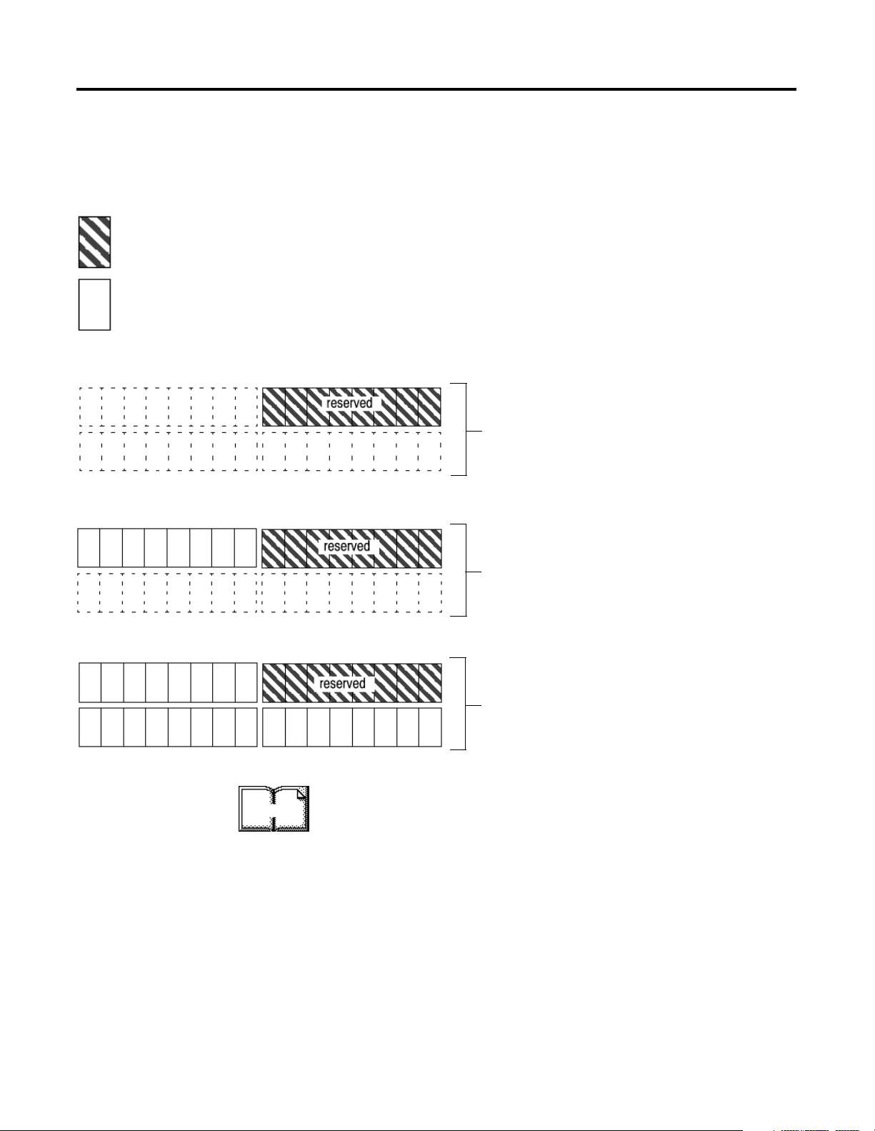
= bits reserved for 1771-SDN and
processor communication
= bits available for discrete
data transfer
Before You Begin 1-5
The concept described below applies to both input and output data
tables. For example, when using your 1771-SDN in 1-slot addressing
mode, you have eight bits of discrete input and eight bits of output
available.
In the scanner’s input and output data tables, there is one byte of memory that is
reserved for communication between the processor and the scanner.
Processor-specific responses from the scanner are read by the processor in this byte
of the input data table. Scanner-specific instructions are written to this byte of the
output data table.
0 bits for discrete data transfer
8 bits for discrete data transfer
24 bits for discrete data transfer
2-slot addressing
In 2-slot addressing mode, the only memory that would have
been available for discrete data transfer (8 bits) is taken up by
scanner/processor communication.
1-slot addressing
In 1-slot addressing mode, there are 16 bits: eight bits for
scanner/processor communication, and eight bits for discrete
data transfer.
1/2-slot addressing
In 1/2-slot addressing mode, there are 32 bits: eight bits used for
scanner/processor communication, and 24 bits for discrete data
transfer.
More
The address density is set via dip switches on the 1771-SDN module
and 1771 chassis. For more information about setting your module’s
address density with switches, refer to the 1771-SDN Scanner Module
Installation Instructions, publication 1771-5.14. For more information
about 1771-module addressing, refer to chapter 3 and to your PLC
programmable controller system-level installation manual and design
manual.
Publication 1771-6.5.132 - June 2000
Page 22
1-6 Before You Begin
A strobe message is a
multicast transfer of data
(which is 64 bits in length)
sent by the 1771-SDN
module that solicits a
response from each strobed
slave device. There is one bit
for each of the possible 64
node addresses. The devices
respond with their data,
which can be as much as 8
bytes.
A poll message is a
point-to-point transfer of
data (0-255 bytes) sent by
the 1771-SDN module that
solicits a response from a
single device. The device
responds with its input data
(0-255 bytes).
A change of state message
is a transfer of data sent
whenever a data change
occurs. A user-configurable
heartbeat rate can also be
set to allow devices to
indicate proper operation
during intervals between
data changes. This does not
solicit response data, but
may receive an acknowledge
message.
A cyclic message is sent only
at a user-configurable rate,
such as every 10 ms.
Communicating with Your Devices
The 1771-SDN module communicates with a device via
and/or
change of state,
cyclic
messages. It uses these messages to solicit
strobe, poll,
data from or deliver data to each device. Data received from the devices,
or input data, is organized by the 1771-SDN module and made available
to the processor. Data received from your PLC-5 processor, or output data,
is organized in the 1771-SDN module and sent on to your devices.
IMPORTANT
Throughout this document,
from the PLC-5 processor’s point of view. Output is data
sent from the PLC-5 processor
collected by the PLC-5 processor
input
and
output
to
a device. Input is data
from
a device.
All data sent and received on a DeviceNet network is in
byte lengths. A device may, for example, produce only
two bits of input information. Nevertheless, since the
minimum data size on a DeviceNet network is one byte,
two bits of information are included in the byte of data
produced by the device. In this example (only two bits of
input information), the upper six bits are insignificant.
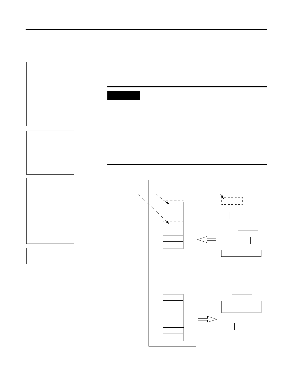
DeviceNet Devices
Input Data From
DeviceNet Devices
A1
Output Data To
DeviceNet Devices
Y
Data from a single device can
be mapped to separate
1771-SDN module memory
locations. For example,
“On/Off” values can be mapped
to one location, diagnostic
values to another, etc. This is
known as “map segmenting”.
This concept is illustrated by
byte A, stored separately as
segments A1 and A2.
,
1771-SDN Scanner Module
Input Data Storage
Byte
A1
B
C
A2
D
E
E
Output Data Storage
X
Y
Y
Y
Y
Z
0
1
2
3
4
5
6
input from the
devices to the
PLC-5 processor
output from
the PLC-5
processor
are defined
A2
B
C
D
E
X
Y
Y
Z
Publication 1771-6.5.132 - June 2000
Page 23
Before You Begin 1-7
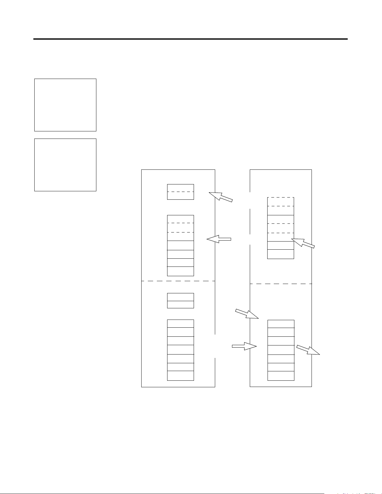
Communicating with Your PLC-5 Processor
A block transfer read (BTR) is
a block transfer of data from
the 1771-SDN module to the
PLC processor. The processor
reading
is
by the 1771-SDN module
(i.e., DeviceNet input data).
A block transfer write (BTW)
is a block transfer of data
from the PLC processor to
the 1771-SDN module. The
processor is
to the 1771-SDN’s memory
(i.e., DeviceNet output data).
the data collected
writing
the data
Your processor communicates with the 1771-SDN scanner module via
block transfer reads, block transfer writes, and DIO transfers.
Input data, gathered from the network’s devices, is organized within
the 1771-SDN and made available for the processor to “read”.
The 1771-SDN module does not send data to your processor.
Data transferred between the module and the processor must be
initiated by the processor. Output data is sent, or “written”, to the
scanner by your processor. This data is organized in the 1771-SDN
module, which in turn passes the data on to your scanned devices via
strobe, poll, change of state, or cyclic messages.
PLC-5 Processor
Discrete Input Image
B
A1
Block Transfer Data File
C
A2
D
E
E
Discrete I/O
Tra n s f e r
I/O Map
Block
Transfer
Read
1771-SDN Scanner
Internal Input
Data Storage
A1
B
C
A2
D
E
E
Input from
the devices
Discrete Output Image
X
Block Transfer Data File
Z
Y
Y
Y
Y
Discrete I/O
Transfer
I/O Map
Block
Transfer
Write
Internal
Output Data
X
Y
Y
Y
Y
Z
Output to
the devices
Publication 1771-6.5.132 - June 2000
Page 24

1-8 Before You Begin
What 1771-SDN Module Data Tables Are and What They Do
To manage the flow of data between your processor and the network
devices, the 1771-SDN module uses the following data tables.
1771-SDN Module Configuration Table
•
Scanlist Table
•
Device Input Data Table
•
Device Output Data Table
•
Device Idle Table
•
Device Failure Table
•
You can configure two of these data tables through RSNetWorx
software. These two tables are stored in the 1771-SDN module’s
non-volatile memory and used to construct all other data tables:
Scanner Configuration Table (SCT)
•
Scanlist Table (SLT)
•
The Scanner Configuration Table (SCT)
The SCT controls basic information your 1771-SDN module needs to
function on your DeviceNet network. It tells your 1771-SDN module:
if it can transmit and receive input and output data
•
how long it waits after each scan before it scans the devices
•
again
when to send out its poll messages
•
The Scanlist Table (SLT)
The SLT supports I/O updating for each of your devices on the
network. It also makes it possible for your 1771-SDN module to make
device data available to your processor. The SLT tells your 1771-SDN
module:
• which device node addresses to scan
Publication 1771-6.5.132 - June 2000
• how to scan each device (strobe, poll, change of state, cyclic or
any valid combination)
• how often to scan your devices
Page 25

Before You Begin 1-9
exactly where in each device’s total data to find the desired data
•
the size of the input data/output data
•
exactly where to map the input or output data for your
•
processor to read or write
Interscan delay is the time between
I/O scans (polled and strobed). It is
the time the 1771-SDN module will
wait between the last poll message
request and the start of the next scan
cycle.
Background poll ratio sets the
frequency of poll messages to a
device in relation to the number of
I/O scans. For example, if the ratio
is set at 10, that device will be
polled once every 10 scans.
RSNetWorx Software as a Configuration Tool
User
Configured
Tab le s
SCT • basic operation
SLT • device-specific
Data In This Table RSNetWorx Configuration
Screen
1771-SDN Module Configuration
• module parameters
• interscan delay
• background poll ratio
Scanlist Editor (SLE)
identification data
• data transfer method
• transmit/receive data size
• input and output data
source and destination
locations
Edit Device I/O Parameters
These values can be configured
automatically through the
AutoMap function or manually
through the Data Table Map.
RSNetWorx for DeviceNet software is used to configure the 1771-SDN
module’s data tables. This software tool connects to the 1771-SDN
module over the DeviceNet network via a PC RS–232 interface
(1770–KFD module), or PC Card (1784-PCD, -PCID, or PCIDS).
TIP
RSNetWorx for DeviceNet software can also
communicate with the 1771-SDN module via a
ControlNet, Ethernet, or Data Highway Plus network.
See chapter 5.
Publication 1771-6.5.132 - June 2000
Page 26
1-10 Before You Begin
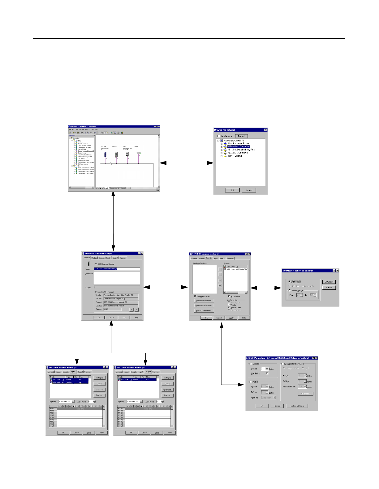
The main RSNetWorx for DeviceNet screen.
The configuration screen map below shows the RSNetWorx for
DeviceNet screens used to configure the 1771-SDN module and the
navigation paths between them. The use of these screens is described
in Chapter 4.
RSNetWorx for DeviceNet Configuration Screen Map
To browse the network,
click on the Online button
and select the driver.
To automatically map input
devices, select the Input tab
and click on the AutoMap
button.
To access the 1771-SDN scanner Module,
double-click on the 1771-SDN icon.
To access the scanlist,
click on the Scanlist tab.
To automatically map output
devices, select the Output tab
and click on the AutoMap
button.
To download the scanlist, click on
the Download to Scanner button.
To edit a device’s I/O parameters,
double-click on the device in
the scanlist.
Publication 1771-6.5.132 - June 2000
Page 27

Before You Begin 1-11
What’s Next?
The remaining sections of this manual provide the following
information:
Chapter 2 covers the configuration process planning stage
•
through a data mapping example.
Chapter 3 describes the hardware setup for the example
•
application.
Chapter 4 covers configuration of the DeviceNet network using
•
RSNetWorx for DeviceNet software.
Chapter 5 describes how to communicate with a DeviceNet
•
network from another network.
Chapter 6 describes how to create, download, and run the
•
example application program.
Chapter 7 covers the diagnostics provided for troubleshooting
•
the 1771-SDN module.
Publication 1771-6.5.132 - June 2000
Page 28

1-12 Before You Begin
Publication 1771-6.5.132 - June 2000
Page 29

Chapter
2
Planning Your Configuration and Data
Mapping Your Devices
This chapter introduces questions you should ask before configuring
your 1771-SDN Scanner. In addition, it presents an example DeviceNet
network and I/O data mapping scheme for a photoeye and a
RediSTATION operator interface module. The following table
identifies what this chapter covers and where to find specific
information.
For information about See page
What You Need to Know 2-1
Beginning the Process 2-1
The Example Network 2-2
Example Network Devices 2-2
Photoeye Input Data Mapping 2-7
Mapping Photoeye Input Data for a Block Transfer Read 2-8
RediSTATION Operator Interface Data Mapping 2-4
Mapping RediSTATION Input Data for a Block Transfer Read 2-5
Mapping RediSTATION Output Data for a Block Transfer Write 2-6
What You Need to Know
Beginning the Process
1 Publication 1771-6.5.132 - June 2000
To map data via your 1771-SDN Scanner module, you must
understand:
your network requirements
•
how input data is mapped
•
• how output data is mapped
Planning before configuring your 1771-SDN module helps make sure
that you can:
• use your memory and bandwidth efficiently
• cater to device-specific needs and requirements
• give priority to critical I/O transfers
• leave room for expansion
Page 30

2-2 Planning Your Configuration and Data Mapping Your Devices
A very important question to answer is “what is on your network?”
You should be familiar with each device’s:
communication requirements
•
I/O importance and size
•
frequency of message delivery
•
You should also ask “how might this network appear in the future?” At
this point in your planning, it is advantageous for you to have some
idea of how the network could be expanded. I/O data mapping can
be performed automatically by the RSNetWorx software. But when
mapping your I/O, you also have the opportunity to allot room for
future I/O. This can save time and effort in the future.
For example, RSNetWorx will automatically map the devices as
efficiently as possible, but the result is that multiple devices may share
the same word location in memory. However, you can also have the
system map the devices such that no two devices share the same
memory location by selecting the “Dword align” option when
performing automapping. You can manually map the devices if you
need to assign them to specific memory locations.
The Example Network
For details refer to the Help screens provided by the RSNetWorx for
DeviceNet software. Additional support can be found at the Rockwell
Software website: http://www.software.rockwell.com.
The following example illustrates a data mapping plan for a
DeviceNet network. Note that even if the mapping is performed
automatically by the RSNetWorx software, you must know where the
devices are mapped in order to use them in your network.
Example Network Devices
This example network has the following devices:
• a PC running RSNetWorx for DeviceNet software
• a 1771-SDN Scanner module interfacing a PLC-5 processor with
DeviceNet
• a Series 9000 photoelectric sensor (strobed)
• a RediSTATION operator interface (polled)
Publication 1771-6.5.132 - June 2000
Page 31

Planning Your Configuration and Data Mapping Your Devices 2-3
PC running Windows NT
or Windows 95/98,
containing RSNetWorx for
DeviceNet software
∗
Node 0
Node 62
IMPORTANT
In the following example, output is data sent to a
device from a controller. Input is data collected from
a device by a controller.
The system you will set up is shown below:
1770-KFD
Communication
Module
DeviceNet Network
Node 7
Node 9
Series 9000
Photoelectric
Sensor
∗
1771-SDN and PLC-5
in 1771 I/O Chassis
* See note below
IMPORTANT
RediSTATION
Operator Interface
Each end of the DeviceNet trunk cable must be
properly terminated with a resistor. Refer to the
DeviceNet Cable Planning and Installation Manual,
publication DN-6.7.2 for detailed information.
Publication 1771-6.5.132 - June 2000
Page 32

2-4 Planning Your Configuration and Data Mapping Your Devices
RediSTATION Operator Interface Data Mapping
The RediSTATION has both inputs and outputs that must be mapped.
The input byte is mapped to the 1771-SDN module’s block transfer
read data table and then to the PLC-5 processor’s input data file. The
output byte is mapped to the 1771-SDN module’s block transfer write
data table and then to the PLC-5 processor’s output data file.
The mapping procedure, using RSNetWorx for DeviceNet software, is
described on pages 4-14 to 4-17.
RediSTATION operator interface
Indicator light
green start light
red start light
The RediSTATION
operator interface
produces one byte of
input data and uses one
byte of output data.
input
output
Two input bits from the RediSTATION will
be mapped: bit 1 for the green Start button
and bit 0 for the red Stop button.
Bit 4 of the input byte indicates if the bulb
is missing.
start bit (green button)
1 byte
7
6543210
1 byte
7
543210
6
One output bit for the RediSTATION’s
indicator light (on/off) will be mapped.
G R
L
stop bit
(red button)
status bit for
indicator light
In the RediSTATION’s bits for the red and green buttons and the
indicator light status bit:
1 = ON
•
• 0 = OFF
Publication 1771-6.5.132 - June 2000
Page 33

Planning Your Configuration and Data Mapping Your Devices 2-5
Mapping RediSTATION Input Data for a Block Transfer Read
The RediSTATION operator interface’s input byte is mapped to the
scanner’s block transfer read data table through a 62 word BTR. In this
example, we use data file N9:0.
What’s Happening?
The bits for the RediSTATION
1
operator interfaces’s red and green
buttons are mapped into the
1771-SDN Scanner’s BTR data
table.
2
The BTR data table is then
transferred via a BTR to the PLC-5
processor’s input data file.
Important: The 1771-SDN module only
makes the data file available for the
processor to read. The 1771-SDN does
not move the data file to the processor.
PLC-5 Processor
Input Data File
N9:0 0000 0000 0000 0000
N9:1 0000 0000 0000 00GR
N9:2 0000 0000 0000 0000
N9:3 0000 0000 0000 0000
N9:4 0000 0000 0000 0000
N9:5 0000 0000 0000 0000
1
Note: This example uses
1-slot addressing.
2
RediSTATION Input Byte
1 byte
1
1771-SDN Scanner Block Transfer Read Data Table
reserved for module status word
G R
R = bit for red button (STOP)
G = bit for green button (START)
= unused bits
= bits reserved for module
status word
G R
Word 0
Word 1
Word 2
Word 3
Word 4
N9:61 0000 0000 0000 0000
1
This mapping is based upon the example in chapter 4.
The mapping for your system may be different.
Example: The green START button from
the RediSTATION appears in the PLC-5
processor’s input file at address N9:1/1.
Word 61
The red STOP button from the
RediSTATION appears in the PLC-5
processor’s input file at address N9:1/0.
Publication 1771-6.5.132 - June 2000
Page 34

2-6 Planning Your Configuration and Data Mapping Your Devices
Mapping RediSTATION Output Data for a Block Transfer Write
The RediSTATION operator interface’s output byte is mapped to the
1771-SDN module’s block transfer write data table. Within the output
byte is bit 0 for the indicator light. The PLC-5’s output data file is
transferred by the processor application to turn the light on or off. In
this example, we use N10 for the output data file.
What’s Happening?
The PLC-5 processor’s output
1
data file containing the indicator
light bit for the RediSTATION is
transferred via a BTW to the
1771-SDN Scanner’s BTW data
table.
2
The BTW data table is then sent
to the RediSTATION via a polled
message from which the
RediSTATION receives its
indicator light bit.
PLC-5 Processor
Output Data File
N10:0 0000 0000 0000 0000
N10:1 0000 0000 0000 000L
N10:2 0000 0000 0000 0000
N10:3 0000 0000 0000 0000
N10:4 0000 0000 0000 0000
N10:5 0000 0000 0000 0000
RediSTATION Output
start/stop station
Note: This example uses
1-slot addressing.
1771-SDN Scanner Block Transfer Write Data Table
reserved for module status word
1
1
1 byte
node address 7
2
L = bit for the station
L
indicator light
= unused bits
= bits reserved for module
status word
Word 0
L
Word 1
Word 2
Word 3
Word 4
N10:61 0000 0000 0000 0000
1
This mapping is based upon the example in chapter 4.
The actual mapping for your system may be different.
Publication 1771-6.5.132 - June 2000
Word 61
Example: The RediSTATION’s indicator light (L) is taken
from N10:1/0 in the PLC-5 processor’s output data file.
Page 35

Planning Your Configuration and Data Mapping Your Devices 2-7
Photoeye Input Data Mapping
The photoelectric sensor (photoeye) inputs are mapped to the
1771-SDN module’s block transfer read data table and then to the
PLC-5 processor’s input data file. The procedure for doing this using
RSNetWorx for DeviceNet software is described on pages 4-14 to 4-17.
The photoeye has no outputs to map.
Series 9000 Photoeye
Two input bits from the photoeye
will be mapped: the status bit
and the data bit.
The photoeye produces
one byte of input data in
response to the strobe
message.
status
bit
input
1 byte
76543210
S D
data
bit
Publication 1771-6.5.132 - June 2000
Page 36

2-8 Planning Your Configuration and Data Mapping Your Devices
Mapping Photoeye Input Data for a Block Transfer Read
The photoeye’s input byte is mapped to the scanner’s block transfer
read data table through a 62 word BTR. In this example, we use data
file N9.
What’s Happening?
The status and data bits from
1
the photoeye are mapped into
the 1771-SDN Scanner’s BTR
data table.
2
The BTR data table is then
transferred via a BTR to the
PLC-5 processor’s input data
file.
Important: The 1771-SDN module only
makes the data available for the
processor to read. The 1771-SDN
module does not move the data to the
processor.
PLC-5 Processor
Input Data File
N9:0 0000 0000 0000 0000
N9:1 0000 00SD 0000 0000
N9:2 0000 0000 0000 0000
N9:3 0000 0000 0000 0000
N9:4 0000 0000 0000 0000
N9:5 0000 0000 0000 0000
1
Note: This example uses
1-slot addressing.
2
Photoeye Input Byte
1 byte
1
1771-SDN Scanner Block Transfer Read Data Table
reserved for module status word
S D
S D
= unused bits
= bits reserved for module
status word
RediSTATION
Word 0
Word 1
Word 2
Word 3
Word 4
N9:61 0000 0000 0000 0000
1
This mapping is based upon the example in chapter 4.
The actual mapping for your system may be different.
Publication 1771-6.5.132 - June 2000
Word 61
Example: The Status bit from the photoeye appears in the PLC-5
processor’s integer file at address N9:1/9.
The Data bit from the photoeye appears in the PLC-5 processor’s
integer file at address N9:1/8.
Page 37

Planning Your Configuration and Data Mapping Your Devices 2-9
What’s Next?
Chapter 3 describes how to set up the system hardware for the
example application.
Publication 1771-6.5.132 - June 2000
Page 38

2-10 Planning Your Configuration and Data Mapping Your Devices
Publication 1771-6.5.132 - June 2000
Page 39

Hardware Setup
Chapter
3
What This Chapter Contains
This chapter describes how to set up the hardware for the example
application. The following table describes what this chapter contains
and where to find specific information.
For information about See page
Installing the 1770-KFD Interface Module 3-1
Installing the PLC-5 Processor 3-2
Setting the I/O Chassis Backplane Switches 3-2
Going Online to the PLC-5 Processor 3-3
Installing the 1785-ENET Ethernet Module 3-5
Installing the 1771-SDN Scanner Module 3-7
Setting the Channel 1 Data Rate and Node Address Switches 3-8
Setting the I/O Chassis Addressing Node Switches 3-8
Installing the Scanner Module in the Chassis 3-9
Connecting the Scanner to the DeviceNet Network 3-10
Installing the RediSTATION Operator Interface 3-11
Installing the Series 9000 Photoeye 3-12
How Your Example System Will Look 3-13
Installing the 1770-KFD Interface Module
More
Connect the RS-232 connector on the 1770-KFD interface module to
one of the serial ports on your PC workstation (e.g., COM1). Connect
the DeviceNet connector on the 1770-KFD module to a DeviceNet
drop or trunk cable. You can make this connection in several ways;
for example, using a DeviceNet Quad Tap (#1492-DN3TW), as shown
on page 3-13.
to PC COM 1
1770-KFD RS-232
Interface Module
DeviceNet
Dropline or
Trun k C able
For detailed directions on how to install the 1770-KFD interface
module, see the DeviceNet RS-232 Interface Module Installation
Instructions, publication 1770-5.6.
1 Publication 1771-6.5.132 - June 2000
Page 40

3-2 Hardware Setup
More
Installing the PLC-5 Processor
Refer to the following figure while installing your PLC-5 processor.
PLC-5C Processor and 1771 I/O Chassis
Locking Bar
ControlNet Node Address Switches
Lift Ejector Tab
PLC-5/40C Processor
Battery
Connector
Battery
Card Guides
DH+ Address
Switches
(on back)
Battery
Cover
O
N
O
FF
1
2
3
4
5
6
7
8
1771 I/O Chassis
Setting the I/O Chassis Backplane Switches
Set the backplane switches in the 1771 I/O chassis for 1-slot
addressing for the example application. To do this, put switch 4 in the
OFF position and switch 5 in the ON position.
Switches Addressing
45
OFF OFF 2 - slot
OFF ON 1 - slot
ON OFF 1/2 - slot
ON ON Not Allowed
For information on setting the other backplane switches
for your system, refer to the ControlNet PLC-5
Programmable Controllers User Manual Phase 1.5,
publication 1785-6.5.22.
ON
OFF
Publication 1771-6.5.132 - June 2000
Page 41

Hardware Setup 3-3
Going Online to the PLC-5 Processor
You cannot go online to the PLC-5 processor over DeviceNet. In order
to download and run the example application program in chapter 6
you must use the processor’s RS-232 connector, or download and run
the program via another network.
Chapter 6 provides examples of downloading and running the
application program via ControlNet, Ethernet, and Data Highway Plus
networks. Chapter 5 provides examples of configuring the DeviceNet
network over these networks.
To go online to the PLC-5 processor via ControlNet:
1. Set the PLC-5C ControlNet node address using the two 10-digit
rotary switches on top of the PLC-5C module.
For the example application we used node address 16.
More
ControlNet PLC-5C processor’s NET address = 16
2
3
1
0
9
8
4
5
6
7
00
00
10
10
90
90
20
20
80
80
30
70
70
30
60
60
40
40
50
50
2. Connect the PLC-5C’s ControlNet port to the ControlNet network.
See Appendix B for information on installing and configuring the
ControlNet driver. See the ControlNet 1.5 PLC-5 Programmable
Controller User Manual, publication 1785-6.5.22, for further
information
.
Publication 1771-6.5.132 - June 2000
Page 42

3-4 Hardware Setup
To go online to the PLC-5 processor via Data Highway Plus:
1. Define the DH+ station address of channel 1A by setting switch
assembly SW-1 on the back of the processor. For the example
application we used address 1. (Set switch 4 in the up position, and
switches 1, 2, 3, 5, and 6 in the down position.)
More
TIP
side view
down
up
See the information on the side of the processor if
you want to use another address.
back view of processor
Switch 4 in the “up” position
Switch 7 in the “up” position.
2. Set the baud rate to 57.6 Kbaud by placing switch 7 in the up
position.
See Appendix C for information on installing and configuring the Data
Highway Plus driver.
Publication 1771-6.5.132 - June 2000
Page 43

Hardware Setup 3-5
Installing the 1785-ENET Ethernet Module
Status Indicator
Transmit Indicator
External Transceiver
Fuse
To go online to the PLC-5 processor via Ethernet, you must install a
1785-ENET module in the 1771 I/O chassis.
The Ethernet module is shipped with a 58-pin connector header that
attaches to the PLC-5 processor.
1. Attach the connector header to the PLC-5 processor.
Connector
Attach the interface
module to this end.
IMPORTANT
Make sure you carefully align the pins and holes
before you press the connector header into the
Header
Push the exposed pins
into the holes on the
PLC-5 processor.
processor. If you improperly align them, you will
bend the connector header pins when you press
them together. Do not use excessive force on the
connector header when seating it into the processor.
You do not need to key the connector.
Channel 3A:
15-pin AUI
Connector Port
2. Use the captive screws to connect the interface module to the
processor.
Publication 1771-6.5.132 - June 2000
Page 44

3-6 Hardware Setup
Be sure power to the
1771 I/O chassis is OFF.
!
3. Insert the interface module/processor combination in the left-most
slot of the 1771 I/O chassis.
4. Assign an IP address to the interface module.
More
5. Configure channel 3A for Ethernet communication.
You can configure the communication channel using BOOTP
software or your PLC-5 programming software. See Appendix A for
information on configuring the communication channel using
RSLogix 5 programming software.
TIP
For more information, see the PLC-5 Ethernet Interface Module User
Manual, publication 1785-6.5.19.
Rockwell Automation offers a BOOTP tool on
http://www.ab.com
Publication 1771-6.5.132 - June 2000
Page 45

Hardware Setup 3-7
Installing the 1771-SDN Scanner Module
MODULE
STATUS
CHANNEL 1
NETWORK
STATUS
NODE/
ERROR CODE
DeviceNet
RESET
Module Status Indicator - indicates
whether the device has power and is
functioning properly.
Reset Button - resets your module.
Channel 1 Status Indicator - gives
diagnostic indications for Channel 1.
Node Address and Status Display displays numeric codes that indicate
scanner node address, status and/or
errors for Channel 1.
Refer to the following figure as you install the 1771-SDN module.
Multi-position Switches - use to set the data rate, chassis
addressing mode, and scanner node address for each channel.
ON
12345678
ON
12345678 12 345678
Data Rate
Switch Settings
ON
= ON = 1
= ON = 1
= OFF = 0
Chassis Address
Switch Settings
= OFF = 0
CHANNEL 2
NETWORK
STATUS
NODE/
ERROR CODE
DeviceNet
Allen-Bradley
1771-SDN
DeviceNet Port 1 - use the color-coded
header to wire your module.
Channel 1 & 2
Node Address Switch Settings
Channel 2 Status Indicator - gives
diagnostic indications for Channel 2.
Node Address and Status Display displays numeric codes that indicate
scanner node address, status and/or
errors for Channel 2.
DeviceNet Port 2 - use the color-coded
header to wire your module.
Left Side of Module
Publication 1771-6.5.132 - June 2000
Page 46

3-8 Hardware Setup
Setting the Channel 1 Data Rate and Node Address Switches
Channel 1
ON
12345678
= ON = 1
= OFF = 0
1. Locate the switchbank labeled “Channel 1” on the left side of the
module.
2. Set the DeviceNet Data Rate for Channel 1 to 500K baud for the
example application by setting switch 1 to an ON (“1”) position
and switch 2 to an OFF (“0”) position.
3. Set the DeviceNet node address for Channel 1 to node 0 for the
example application by setting switches 3 through 8 to the OFF
(“0”) position.
TIP
Refer to the table on the left side of the module to
set the channel to a different node address. The
address range is 0 to 63.
IMPORTANT
The node address setting must not conflict with the
node address of any other device on the network.
Note that channel 2 is not used for the example
application.
Configuration
ON
12345678
= ON = 1
= OFF = 0
Setting the I/O Chassis Addressing Node Switches
Set the I/O chassis addressing mode to 1-slot for the example
application.
1. Locate the switchbank labeled “Configuration” on the left side of
the module.
2. Set switch 7 to an OFF (“0”) position and switch 8 to an ON (“1”)
position.
IMPORTANT
IMPORTANT
Make sure switches 1 through 6 in the Configuration
switchbank always remain in the OFF (“0”) position.
The chassis addressing mode setting for the 1771 I/O
chassis (page 3-2) must match the I/O chassis
address setting of the scanner. If the switches do not
match, data will be lost in the data transfer between
the PLC-5 processor and the scanner module.
Publication 1771-6.5.132 - June 2000
Page 47

Installing the Scanner Module in the Chassis
Hardware Setup 3-9
ATTENTION
Do not install the 1771-SDN Scanner Module with the
chassis power supply on. Turn off the chassis power
supply. You will disrupt backplane communication
and may damage your module.
!
1. Select a slot for the 1771-SDN module in the chassis. You may use
any slot except the leftmost slot, which is reserved for the PLC-5
processor. For the example application, we installed the scanner in
slot 1.
2. Insert the 1771-SDN Scanner module into the slot.
Apply firm, even pressure to seat the module in the I/O chassis
backplane connectors.
Publication 1771-6.5.132 - June 2000
Page 48

3-10 Hardware Setup
Connecting the Scanner to the DeviceNet Network
ATTENTION
Do not wire your module with power applied to
your network. You may short circuit your network or
disrupt communication.
!
To connect to the DeviceNet network:
1. Connect the DeviceNet drop line to the linear plug provided with
the scanner. Match the wire insulation colors to the colors shown
on the label.
Module label shows
wiring color scheme
RED
WHITE
BARE
BLUE
BLACK
Front of
Scanner
Module
ERROR CODE
ERROR CODE
MODULE
STATUS
RESET
CHANNEL 1
NETWORK
STATUS
NODE/
Device
Net
CHANNEL 2
NETWORK
STATUS
NODE/
Device
Net
Publication 1771-6.5.132 - June 2000
2. Locate the DeviceNet port connector for Channel 1 on the front of
the module.
3. Insert the linear plug into the five-pin header for Channel 1.
Channel 1 Port
Connector
Dedicated DeviceNet
Drop Line
Page 49

Hardware Setup 3-11
Installing the RediSTATION Operator Interface
More
Begin installing the RediSTATION by removing the six screws
fastening the cover and setting the DIP switches inside as follows:
Set this position To this value:
1
2
3
4
5
6
7
8
9
10
1
The DeviceNet address is 000111 (node 7).
2
The data rate is 10 (500k bps).
1On
1On
1 On (node
0 Off address
0Off
0Off
0 Off (data
2
1On rate
)
0Off
0Off
1
)
The output fault rate is 0 (outputs turned off).
The output flash rate is 0 (outputs tuned off).
See Chapter 2 of the RediSTATION Operator Interface User Manual,
publication 2705-804, for complete information about setting the DIP
switches to configure the node address, data rate, output flash rate,
and output fault state.
Refer to the following illustration as you connect the RediSTATION to
the network.
TIP
You do not need to
disconnect incoming
power from the
DeviceNet network
before connecting
DeviceNet Cable
the RediSTATION.
The DeviceNet cable connects directly
to the mini connector on the top of the
RediSTATION enclosure or through the
conduit opening (open style).
mini
connector
open
style
Publication 1771-6.5.132 - June 2000
Page 50

3-12 Hardware Setup
Installing the Series 9000 Photoeye
Connect the photoeye to the network and configure the photoeye as
follows:
Node Address: 9
•
Operating Mode: Light Operate (default)
•
Baud Rate: 500 kb
•
Top View of Series 9000 Photoeye
Programming
Pushbutton
Sensitivity
Adjustment
Yellow - Output
Green - Margin
Red/Green - Status
More
For detailed directions, see the instructions that came with your
photoeye.
Publication 1771-6.5.132 - June 2000
Page 51

Hardware Setup 3-13
How Your Example System Will Look
When you have finished installing all the devices, your example
system should look similar to the one shown below:
PC running Windows NT
or Windows 95/98,
containing RSNetWorx for
DeviceNet software
PC Serial
Port
Node 0
PLC-5 Processor with 1771-SDN
module in 1771 I/O chassis
1770-KFD
Communication
Module
Node 62
Series 9000
Photoelectric
Sensor
24V
Node 9
1492-DN3TW
Quad Tap
Node 7
RediSTATION
Operator Interface
What’s Next?
IMPORTANT
Make sure each end of your DeviceNet trunk cable
is properly terminated with a resistor. Refer to the
DeviceNet Cable Planning and Installation Manual,
publication DN-6.7.2 for detailed information.
The next step is to configure the 1771-SDN module and perform I/O
data mapping using RSNetWorx for DeviceNet software.
Publication 1771-6.5.132 - June 2000
Page 52

3-14 Hardware Setup
Publication 1771-6.5.132 - June 2000
Page 53

Configuring the DeviceNet Network
Chapter
4
What This Chapter Contains
Installing the Software
This chapter describes how to configure the DeviceNet network using
RSLinx and RSNetWorx for DeviceNet software. The following table
describes what this chapter contains and where to find specific
information.
For information about See page
Installing the Software 4-1
Using RSLinx to Configure the DeviceNet Driver 4-2
Using RSNetWorx for DeviceNet to Configure the Scanlist 4-4
Setting Up an Online Connection 4-4
Setting the 1771-SDN Node Address 4-6
Configuring the I/O Devices 4-9
Verifying the Photoeye Configuration 4-12
Verifying the RediSTATION Configuration 4-13
AutoMapping the Devices into the Scanlist 4-14
Install the RSLinx and RSNetWorx software.
1. Insert the CD in the CD-ROM drive.
Note: The CD-ROM supports Windows Autorun. Once inserted into
the CD-ROM drive, if you have Autorun configured, the installation
will automatically start at the first setup screen.
If Autorun is not configured for your CD-ROM drive, go to step 2.
2. From the Start menu, choose Run.
You will see the Run pop-up window.
3. Type d:/setup (if it doesn’t appear automatically), where d: is your
CD-ROM driver letter.
4. Click on OK.
You see the progress bar, followed by the welcome screen.
1 Publication 1771-6.5.132 - June 2000
Page 54

4-2 Configuring the DeviceNet Network
Using RSLinx to Configure the DeviceNet Driver
After you install the software, you use RSLinx to configure your
DeviceNet driver and RSNetWorx for DeviceNet to configure the
network.
1. Start the RSLinx software.
2. From the Communications menu, select Configure Drivers. The
Configure Drivers window will appear.
Publication 1771-6.5.132 - June 2000
3. From the list of Available Drivers, select DeviceNet Drivers and
click on Add/New.
You will see the following list of drivers:
4. Select the Allen-Bradley 1770-KFD driver.
Page 55

Your driver setup will vary according to your system
setup (COM port, Data Rate, Node Address). Choose
the appropriate settings for your system. We set the
DeviceNet Port Setup Data Rate to 500K for the
example application.
Configuring the DeviceNet Network 4-3
The Allen-Bradley 1770-KFD Driver Configuration window will
appear.
5. Configure the driver using the example above as a guide and click
on OK. The software will take a few seconds to configure the
driver. When it is done the following prompt will appear:
6. Select the default driver name 1770-KFD-1 and click on OK.
7. Close RSLinx.
You will use the driver you just configured to browse and configure
the network with RSNetWorx for DeviceNet.
Publication 1771-6.5.132 - June 2000
Page 56

4-4 Configuring the DeviceNet Network
Using RSNetWorx for DeviceNet to Configure the Scanlist
Setting Up an Online Connection
Follow the procedure below to set up an online connection to the
DeviceNet network using the 1770-KFD driver.
1. Start RSNetWorx.
2. From the File menu, select New.
If you have RSNetWorx for ControlNet installed on your computer
you may see the following window. Otherwise, proceed to step 4.
3. Highlight DeviceNet Configuration and click on OK.
4. Click on the Online button on the toolbar.
Publication 1771-6.5.132 - June 2000
Page 57

Configuring the DeviceNet Network 4-5
The Browse for network window will appear. You will see the
drivers you have configured on your system.
5. Select the 1770-KFD-1, DeviceNet driver and click on OK.
You will be prompted to upload or download devices before going
online.
6. Click on OK to go online and upload the network.
RSNetWorx for DeviceNet will begin browsing for network devices.
When the software is finished browsing, the network displayed on
your screen should look similar to the one shown below.
Publication 1771-6.5.132 - June 2000
Page 58

4-6 Configuring the DeviceNet Network
TIP
RSNetWorx for DeviceNet performs a one-shot
browse when you go online or choose the browse
feature. The software will poll for devices once and
display the results. If a node which was online later
goes offline, there will be no “live” indication in
RSNetWorx. You must manually perform a browse to
detect the missing node.
To perform the browse, press the button.
Setting the 1771-SDN Node Address
Once the devices are uploaded, their node addresses appear to the
right of their icons. For the example application, the 1771-SDN
scanner module should have a node address of “0” (or “00”). If you
need to change a module’s node address, use the following
procedure.
TIP
You can use this procedure to change the node
address of other devices on the network (e.g., the
Photoeye). You can also change the network data
rate (baud rate) of some devices. Power must be
cycled for baud rate changes to take effect.
If “00” appears to the right of the 1771-SDN icon and you do not need
to change the node address or baud rate of any device, skip the
remainder of this section and go to “Configuring the I/O Devices” on
page 4-9.
IMPORTANT
The network must not be active when performing
node commissioning on the 1771-SDN module. Make
sure the processor is in Program mode.
(Note that this applies only to the 1771-SDN. You
may commission other devices with the processor in
Run mode.)
Publication 1771-6.5.132 - June 2000
Page 59

Configuring the DeviceNet Network 4-7
To change the node address of a device perform the following steps:
1. From the Tools menu select Node Commissioning.
2. Click on the Browse button.
You will see the Device Selection window.
3. Select the 1770-KFD-1 driver.
Publication 1771-6.5.132 - June 2000
Page 60

4-8 Configuring the DeviceNet Network
The devices on the network will appear in the right panel.
4. Select the device from the right panel and click on OK.
You will see the Node Commissioning window with the current
settings for the device. Your window will look similar to the one
shown below.
Publication 1771-6.5.132 - June 2000
5. In the New Device Settings: Node Address box, enter the new
node address (e.g., a 0 as shown above).
6. Click on Apply.
7. Click on Exit to close the window.
Page 61

Configuring the DeviceNet Network 4-9
Configuring the I/O Devices
Next you must add the RediSTATION and the photoeye to the
1771-SDN’s scanlist, configure and/or verify their parameters, and map
them to the PLC-5 processor’s memory.
1. Double-click on the 1771-SDN module icon.
The following window will appear:
2. Select the Module tab.
Publication 1771-6.5.132 - June 2000
Page 62

4-10 Configuring the DeviceNet Network
You will be prompted to upload or download the configuration.
3. Click on Upload.
After uploading the Module page will appear:
Publication 1771-6.5.132 - June 2000
4. Make sure the 1771-SDN module’s Rack and Group numbers are
correct. We used Rack 0, Group 1 for the example application.
TIP
We used the Module Defaults for the other settings.
For an explanation of the other settings (Import
and Export, PLC Interface Address, etc.) click on
the Help button.
5. Select the Scanlist tab.
Page 63

Configuring the DeviceNet Network 4-11
The Scanlist page will appear with the RediSTATION and the
photoeye in the list of Available Devices.
6. For this example, uncheck the Automap on Add box, as shown
above. You will do this mapping later.
7. Click on the double arrow button to add the photoeye and
RediSTATION to the Scanlist.
The photoeye and the RediSTATION will appear in the Scanlist in
the right panel.
8. Click on OK.
Publication 1771-6.5.132 - June 2000
Page 64

4-12 Configuring the DeviceNet Network
You will be prompted to download the changes to the device (i.e.,
the scanner).
9. Click on Yes.
IMPORTANT
The PLC-5 processor must be in Program mode to
download the scanlist to the 1771-SDN module.
Verifying the Photoeye Configuration
1. Double-click on the 1771-SDN module icon and again select the
Scanlist tab.
Publication 1771-6.5.132 - June 2000
2. Double-click on the photoeye in the Scanlist.
Page 65

Configuring the DeviceNet Network 4-13
The Edit I/O Parameters window will appear for the photoeye.
The I/O parameters define the configuration for the device in terms
of how much and what data the device will exchange with the
1771-SDN module. By default, the photoeye will send 1 byte when
it receives a strobe request. Recall from chapter 3 that the output of
the photoeye will be returned in bit 0 of that byte.
3. Verify that the photoeye parameters are set as shown above. Make
any changes as necessary and click on OK.
4. Close the Edit I/O Parameters window for the photoeye.
Verifying the RediSTATION Configuration
1. Double-click on the RediSTATION in the Scanlist window. The
Edit I/O Parameters window will appear for the RediSTATION.
2. Make sure that the Polled box is checked and that the Rx Size and
Tx Size are each 1 byte.
Publication 1771-6.5.132 - June 2000
Page 66

4-14 Configuring the DeviceNet Network
3. Click on OK if you made any changes and close the Edit I/O
Parameters window for the RediSTATION.
4. Click on OK again. You will be prompted to download the changes
to the 1771-SDN module.
5. Click on Yes to download the new configuration.
AutoMapping the Devices into the Scanlist
Follow the procedure below to automatically map the photoeye and
RediSTATION to the PLC-5 processor.
There are six available blocks.
Block Xfer 62 is the default.
TIP
If you want to know how to map the devices
manually, click on the Help button at the bottom of
the screen and select “Map device input data
manually”.
1. Double-click on the 1771-SDN module icon and select the Input
tab. You will see the following window.
Publication 1771-6.5.132 - June 2000
2. Highlight the RediSTATION and the photoeye as shown above and
click on the AutoMap button.
Page 67

File N9,
Word 1
Configuring the DeviceNet Network 4-15
The resulting device mapping will appear in the lower panel of the
window:
Note: The source address is actually
determined by the block transfer
instruction in the ladder logic. See
chapter 6.
Photoeye
inputs
RediSTATION
inputs
In this example, the input byte from the RediSTATION will appear
in the PLC-5 processor in file N9, word 1, as bits 0-7. Recall from
chapter 2 that the START button is bit 1 and the STOP button is bit
0. Therefore, the addresses for the RediSTATION inputs are:
START N9:1.1
STOP N9:1.0
The input byte from the photoeye will appear in the PLC-5
processor in file N9, word 1, as bits 8-15. Recall from chapter 3 that
the input bit is bit 0. Therefore, the address of the photoeye input
bit is:
N9:1.8
3. Note the addresses assigned to the START and STOP buttons
and the photoeye in your system. You will enter these addresses
in the example ladder program.
Publication 1771-6.5.132 - June 2000
Page 68

4-16 Configuring the DeviceNet Network
4. Select the Output tab.
File N10,
Word 1
Note: The destination address is
actually determined by the block
transfer instruction in the ladder
logic. See chapter 6.
Highlight the RediSTATION as shown above and click on the
AutoMap button. The mapping of the RediSTATION will appear in
the lower panel.
After mapping the
RediSTATION output
address will appear
here.
In this example, the output to the RediSTATION appears in the
PLC-5 processor in file N10, word 1, as the lower byte (bits 0-7).
Recall from chapter 3 that the indicator light is output bit 0.
Therefore, the address for the RediSTATION’s indicator light is:
Publication 1771-6.5.132 - June 2000
N10:1.0
5. Note the address assigned to this output in your system. You
will enter this address in the example ladder logic program.
Page 69

Configuring the DeviceNet Network 4-17
Download the Configuration to the Scanner
1. Click on the Scanlist tab and then on the Download to Scanner
button.
You will see this window:
2. Select Channel A (default).
What’s Next?
Note: Both channels will download.
3. Select All Records.
4. Click on the Download button to download the configuration to
the 1771-SDN scanner module.
5. Click on the OK button to complete the DeviceNet scanner
configuration.
6. Select the Save as option from the File menu, and save the
DeviceNet configuration, using an appropriate name, e.g.,
1771-SDN.dnt.
7. Close the RSNetWorx for DeviceNet software.
The next chapter describes how to configure the DeviceNet network
remotely from other networks: Ethernet, ControlNet, and Data
Highway Plus.
Publication 1771-6.5.132 - June 2000
Page 70

4-18 Configuring the DeviceNet Network
Publication 1771-6.5.132 - June 2000
Page 71

Communicating with DeviceNet
from Another Network
Chapter
5
What This Chapter Contains
This chapter describes how to communicate with the DeviceNet
network from another network, using the PLC-5 “pass-through”
feature. This feature can be used to adjust and fine tune the nodes on
your network. Examples are provided for communicating from a
ControlNet network, an Ethernet network, and a Data Highway Plus
network.
ATTENTION
!
IMPORTANT
The pass-through feature is not intended to replace a
1770-KFD, PCD, PCID, or PCIDS connection to the
network:
Pass-through is intended only for fine tuning and
•
adjustment of your network devices. Do not
attempt to configure your entire network using a
pass-through driver, or a time-out may occur.
The pass-through method is not suitable for real
•
time monitoring of your network devices.
To use the pass-through feature you must have the
following versions of the RSLinx software and
1771-SDN module firmware:
Component Software/Firmware Version
RSLinx software 2.10 or higher
1771-SDN module 4.003 or higher
You must have previously set up the network you will use to
communicate with the DeviceNet network and have installed and
configured the appropriate drivers and interface hardware. The 1771
I/O chassis used for these examples was set up with the following
hardware mapping:
Module Rack Group Slot IP Address
PLC-5C/1785-ENET 0 0 0 130.130.130.2
1771-SDN 0 1 0 n/a
1 Publication 1771-6.5.132 - June 2000
Page 72

5-2 Communicating with DeviceNet from Another Network
The following table describes what this chapter contains and where to
find specific information.
For information about See page
Where to Find More Information 5-2
Communicating with DeviceNet from a ControlNet Network 5-3
Communicating with DeviceNet from an Ethernet Network 5-9
Communicating with DeviceNet from a DH+ Network 5-18
Where to Find
More
Refer to the following publications for information on configuring
other networks:
More Information
For information about: See this publication: Publication number:
the ControlNet PLC-5 processor ControlNet PLC-5 Programmable Controllers User Manual 1785-6.5.22
the Ethernet interface module PLC-5 Ethernet Interface Module User Manual 1785-6.5.19
TCP/IP protocol and networking in general Comer, Douglas E.,
Protocols and Architecture
N.J.:Prentice-Hall, 1995. ISBN 0-13-216987-8.
Tannebaum, Andrew S.
Cliffs, N.J.: Prentice-Hall, 1989. ISBN 0-13-162959-
Internetworking with TCP-IP, Volume 1:
, 2nd ed. Englewood Cliffs,
Computer Networks
, 2nd ed. Englewood
X
.
n/a
n/a
Publication 1771-6.5.132 - June 2000
Page 73

Communicating with DeviceNet from Another Network 5-3
Communicating with DeviceNet from a ControlNet Network
Before performing this example the ControlNet network must be
configured and running. A ControlNet processor (PLC-5C) is required.
In this example the PLC-5C processor is configured as ControlNet
node 16. Use your own ControlNet PLC-5C processor’s configuration
when performing this example.
Configuring the DeviceNet Pass-Through Driver
Before you can communicate with the 1771-SDN module via the
ControlNet network, you must first configure the DeviceNet
pass-through driver (1771-SDNPT) with a ControlNet port. RSLinx,
version 2.10 or higher, is required.
To configure the ControlNet pass-through driver perform the
following steps:
1. Start RSLinx.
2. From the Communications menu, select Configure Drivers.
3. From the list of Available Driver Types select DeviceNet Drivers
and click on Add/New.
Publication 1771-6.5.132 - June 2000
Page 74

5-4 Communicating with DeviceNet from Another Network
You will see the following list of drivers.
4. Select the Allen-Bradley 1771-SDNPT driver. The Driver
Configuration window will appear.
Publication 1771-6.5.132 - June 2000
5. Select a pass-through port to be configured from the pull-down list,
e.g., Port 1.
6. Expand your installed ControlNet driver (AB_KTC-1 in the
example) and highlight your PLC-5C processor.
7. Select the 1771-SDN Backplane Address Configuration. We
used the following configuration for the example application.
Rack 0
Group 1
Slot 0
8. Select the DeviceNet Channel (Channel 1 for the example
application).
Page 75

Communicating with DeviceNet from Another Network 5-5
9. Click on OK.
You will see the following warning:
10. Verify that the routing information is accurate and click on the Yes
button.
You will be prompted to choose a name for the driver.
11. Enter an appropriate driver name (e.g., 1771-SDNPT-1) and click
on the OK button.
The new driver will be added to the Configured Drivers in
RSLinx. (Your list will contain the drivers you have configured.)
12. Close or Minimize RSLinx.
Publication 1771-6.5.132 - June 2000
Page 76

5-6 Communicating with DeviceNet from Another Network
Communicating with the DeviceNet Network
Once you have the ControlNet pass-through driver configured, you
can use RSNetWorx for DeviceNet to communicate with the DeviceNet
network via the ControlNet network.
Perform the following steps:
1. Start RSNetWorx.
Publication 1771-6.5.132 - June 2000
2. From the File menu, select New.
If you have RSNetWorx for ControlNet installed on your computer
you may see the following window. Otherwise, proceed to step 4.
3. Select DeviceNet Configuration and click on OK.
4. Click on the Online button on the toolbar.
Page 77

Communicating with DeviceNet from Another Network 5-7
The Browse for network window will appear. You will see the
drivers you have configured on your system.
5. Highlight your DeviceNet pass-through driver (1771-SDNPT-1
above) and click on OK.
You will receive the following prompt:
6. Click on OK to upload the devices. RSNetWorx for DeviceNet will
begin browsing for network devices.
ATTENTION
!
Performing a pass-through browse via the
ControlNet network will take longer than browsing
using the 1770-KFD DeviceNet driver as described in
chapter 4.
Note that due to the time required, the pass-through
method is not suitable for configuring a network nor
for real time monitoring of your network devices.
Publication 1771-6.5.132 - June 2000
Page 78

5-8 Communicating with DeviceNet from Another Network
When RSNetWorx for DeviceNet is finished browsing, the network
displayed on your screen should look similar to the one shown
below.
You are now communicating with the DeviceNet network via the
ControlNet network. See pages 4-6 to 4-17 of this manual for
examples of how to use RSNetWorx for DeviceNet to adjust network
parameters.
Publication 1771-6.5.132 - June 2000
Page 79

Communicating with DeviceNet from Another Network 5-9
Communicating with DeviceNet from an Ethernet Network
More
Before performing this example the Ethernet network must be
configured and running. A 1785-ENET module must be installed on
the PLC-5 processor and connected to the network.
See the PLC-5 Ethernet Interface Module User Manual (publication
1785-6.5.19) for more information.
Establishing Ethernet pass-through communications involves four
main steps:
1. You use RSLinx to configure the Ethernet to PLC-5 driver. This
procedure is described on pages 5-9 to 5-11.
2. You configure the 1785-ENET module’s communications channel
and download the configuration to the PLC-5 processor. This can
be done using RSLogix 5 software when you create the example
ladder program. The Ethernet channel configuration is described in
Appendix A.
3. You use RSLinx to configure the DeviceNet pass-through driver to
communicate with the 1771-SDN module via the Ethernet network.
This procedure is described on pages 5-12 to 5-15.
4. You use the pass-through driver with RSNetWorx for DeviceNet
software to adjust and tune your DeviceNet network. This
procedure is described on pages 5-15 to 5-17.
Configuring the Ethernet to PLC-5 Communications Driver
To communicate with your PLC-5 processor over an Ethernet network
you must configure the Ethernet to PLC-5 driver. Perform the
following steps to configure the driver using RSLinx software.
1. Start RSLinx.
Publication 1771-6.5.132 - June 2000
Page 80

5-10 Communicating with DeviceNet from Another Network
2. From the Communications menu, select Configure Drivers.
3. From the list of Available Driver Types, select the Ethernet to
PLC-5/SLC-5/5820-EI driver and click on Add New.
You will be prompted to choose a name for the new driver.
4. Enter an appropriate driver name (e.g., AB_ETH-1) and click on
the OK button.
The Configure driver for Ethernet to PLC-5/SLC-5/5820-EI
window will open.
Publication 1771-6.5.132 - June 2000
Page 81

Communicating with DeviceNet from Another Network 5-11
5. In the IP address or hostname field, enter the IP address of the
PLC-5 processor (130.130.130.2 in this example).
IMPORTANT
You must configure the PLC-5’s communications
using BOOTP software or your PLC-5 programming
software (e.g., RSLogix 5) before you will be able to
communicate with the PLC-5 using this Ethernet
address. See Appendix A for information on
configuring the PLC-5’s communications using
RSLogix 5.
6. Click on the Accept button. Then click on OK.
The new driver will be added to the list of Configured Drivers in
RSLinx. (Your list will contain the drivers you have configured.)
Publication 1771-6.5.132 - June 2000
Page 82

5-12 Communicating with DeviceNet from Another Network
Configuring the DeviceNet Pass-Through Driver
Before you can communicate with the 1771-SDN module via the
Ethernet network, you must configure the DeviceNet pass-through
driver (1771-SDNPT). RSLinx, version 2.10 or higher, is required.
Connect your 1785-ENET module to your Ethernet network. Then
perform the following steps.
1. Start RSLinx.
2. From the Communications menu, select Configure Drivers.
3. From the list of Available Driver Types select DeviceNet Drivers
and click on Add/New.
Publication 1771-6.5.132 - June 2000
Page 83

Communicating with DeviceNet from Another Network 5-13
You will see the following list of drivers.
4. Select the Allen-Bradley 1771-SDNPT driver.
The Allen-Bradley 1771-SDNPT Driver Configuration window
will open.
5. Select a pass-through port to be configured from the pull-down list,
e.g., Port 2.
6. Expand your Ethernet driver (AB_ETH-1) and highlight your PLC-5
processor.
Publication 1771-6.5.132 - June 2000
Page 84

5-14 Communicating with DeviceNet from Another Network
7. Select the 1771-SDN Backplane Address Configuration. We
used the following configuration for the example application.
Rack 0
Group 1
Slot 0
8. Select the DeviceNet channel (Channel 1 for the example
application).
9. Click on OK.
You will see the following warning:
10. Verify that the routing information is accurate and click on the Yes
button.
You will be prompted to enter a name for the driver.
11. Enter an appropriate driver name (e.g., 1771-SDNPT-2) and click
on the OK button.
Publication 1771-6.5.132 - June 2000
Page 85

Communicating with DeviceNet from Another Network 5-15
The new driver will be added to the list of Configured Drivers in
RSLinx. (Your list will contain the drivers you have configured.)
12. Close or Minimize RSLinx.
Communicating with the DeviceNet Network
Once you have the Ethernet pass-through driver configured, you can
use RSNetWorx for DeviceNet to communicate with the DeviceNet
network via the Ethernet network.
Perform the following steps:
1. Start RSNetWorx.
Publication 1771-6.5.132 - June 2000
Page 86

5-16 Communicating with DeviceNet from Another Network
2. From the File menu, select New.
If you have RSNetWorx for ControlNet installed on your computer
you may see the following window. Otherwise, proceed to step 4.
3. Select DeviceNet Configuration and click on OK.
4. Click on the Online button on the toolbar.
The Browse for network window will appear. You will see the
drivers you have configured on your system.
Publication 1771-6.5.132 - June 2000
5. Highlight the 1771-SDNPT-2, DeviceNet driver and click on OK.
Page 87

Communicating with DeviceNet from Another Network 5-17
You will receive the following prompt:
6. Click on OK to upload the devices. RSNetWorx for DeviceNet will
begin browsing for network devices.
ATTENTION
!
When RSNetWorx for DeviceNet is finished browsing, the network
displayed on your screen should look similar to the one shown
below.
Performing a pass-through browse via the Ethernet
network will take longer than browsing using the
1770-KFD DeviceNet driver as described in
chapter 4.
Note that due to the time required, the pass-through
method is not suitable for configuring a network nor
for real time monitoring of your network devices.
You are now communicating with the DeviceNet network via the
Ethernet network. See pages 4-6 to 4-17 of this manual for
examples of how to use RSNetWorx for DeviceNet to adjust
network parameters.
Publication 1771-6.5.132 - June 2000
Page 88

5-18 Communicating with DeviceNet from Another Network
Communicating with DeviceNet from a DH+ Network
Before performing this example the DH+ network must be configured
and running. In this example, the PLC-5 processor’s DH+ channel A is
configured as node 1. Use your own DH+ configuration when
performing this example.
Configuring the DeviceNet Pass-Through Driver
Before you can communicate with the 1771-SDN module via a DH+
network, you must first configure the DeviceNet pass-through driver
(1771-SDNPT) with a DH+ port. RSLinx, version 2.10 or higher, is
required.
Perform the following steps.
1. Start RSLinx.
Publication 1771-6.5.132 - June 2000
2. From the Communications menu, select Configure Drivers.
The Configure Drivers window will appear.
3. Select DeviceNet Drivers from the Available Driver Types
pull-down list and click on Add/New.
Page 89

Communicating with DeviceNet from Another Network 5-19
You will see the following list of drivers.
4. Select the Allen-Bradley 1771-SDNPT driver.
The Driver Configuration window will appear.
5. Select a pass-through port to be configured from the pull-down list,
e.g., Port 3.
6. Expand your DH+ driver (AB_KT-1 above) and highlight the PLC-5
processor.
7. Select the 1771-SDN Backplane Address Configuration. We
used the following configuration for the example application.
Rack 0
Group 1
Slot 0
8. Select the DeviceNet Channel (Channel 1 for the example
application).
Publication 1771-6.5.132 - June 2000
Page 90

5-20 Communicating with DeviceNet from Another Network
9. Click on OK.
You will see the following warning:
10. Verify that the routing information is accurate and click on the Yes
button.
You will be prompted to enter a name for the driver.
11. Enter an appropriate driver name (e.g., 1771-SDNPT-3) and click
on the OK button.
The new driver will be added to the Configured Drivers in
RSLinx. (Your list will contain the drivers you have configured.)
12. Close or Minimize RSLinx.
Publication 1771-6.5.132 - June 2000
Page 91

Communicating with DeviceNet from Another Network 5-21
Communicating with the DeviceNet Network
Once you have the DH+ pass-through driver configured, you can use
RSNetWorx for DeviceNet to communicate with the DeviceNet
network via the DH+ network.
Perform the following steps:
1. Start RSNetWorx.
2. From the File menu, select New.
If you have RSNetWorx for ControlNet installed on your computer
you may see the following window. Otherwise, proceed to step 4.
3. Select DeviceNet Configuration and click on OK.
4. Click on the Online button on the toolbar.
Publication 1771-6.5.132 - June 2000
Page 92

5-22 Communicating with DeviceNet from Another Network
The Browse for network window will appear. You will see the
drivers you have configured on your system.
5. Highlight the 1771-SDNPT-3 driver and click on OK.
You will receive the following prompt:
6. Click on OK to upload the devices. RSNetWorx for DeviceNet will
begin browsing for network devices.
ATTENTION
!
Performing a pass-through browse via the DH+
network will take longer than browsing using the
1770-KFD DeviceNet driver as described in
chapter 4.
Note that due to the time required, the pass-through
method is not suitable for configuring a network nor
for real time monitoring of your network devices.
Publication 1771-6.5.132 - June 2000
Page 93

Communicating with DeviceNet from Another Network 5-23
When RSNetWorx for DeviceNet is finished browsing, the network
displayed on your screen should look similar to the one shown
below.
You are now online to the DeviceNet network via the Data Highway
Plus network. See pages 4-6 to 4-17 of this manual for examples of
how to use RSNetWorx for DeviceNet to adjust network parameters.
What’s Next?
The next chapter describes how to create and run the example
application program to test the DeviceNet Network.
Publication 1771-6.5.132 - June 2000
Page 94

5-24 Communicating with DeviceNet from Another Network
Publication 1771-6.5.132 - June 2000
Page 95

Creating and Running the Example
Application Program
Chapter
6
What This Chapter Contains
This chapter describes the procedure to create, download, and run an
example ladder logic program to test the DeviceNet network. When
the program is put into Run mode, pressing the START button on the
network’s RediSTATION will cause the red indicator light to come on
and stay on until the STOP button is pressed. Passing an object in
front of the photoeye will increment a counter.
This chapter provides examples of downloading and running the
program over ControlNet, Ethernet, and Data Highway Plus networks.
You cannot directly communicate with the PLC-5 processor over the
DeviceNet network.
The 1771 I/O chassis used for these examples was set up with the
following hardware:
Module Rack Group Slot IP Address
PLC-5/1785-ENET 0 0 0 130.130.130.2
1771-SDN 0 1 0 n/a
The following table describes what this chapter contains and where to
find specific information.
For information about See page
Installing the Software 6-2
Creating the Example Application Program 6-2
Downloading and Running the Program 6-6
Downloading and Running the Program via a ControlNet Network 6-6
Downloading and Running the Program via an Ethernet Network 6-9
Downloading and Running the Program via a DH+ Network 6-12
For more information, see Getting Results With RSLogix 5, Rockwell
More
1 Publication 1771-6.5.132 - June 2000
Software publication 9399-RL53GR.
Page 96

6-2 Creating and Running the Example Application Program
Installing the Software
Creating the Example Application Program
Install the RSLogix 5 software.
1. Insert the CD in the CD-ROM drive.
Note: The CD-ROM supports Windows Autorun. Once inserted into
the CD-ROM drive, if you have Autorun configured, the installation
will automatically start at the first setup screen.
If Autorun is not configured for your CD-ROM drive, go to step 2.
2. From the Start menu, choose Run.
You will see the Run pop-up window.
3. Type d:/setup (if it doesn’t appear automatically), where d: is your
CD-ROM driver letter.
4. Click on OK.
You see the progress bar, followed by the welcome screen.
Perform the following steps to create the example application
program.
1. Start RSLogix 5.
2. From the File menu select New.
Publication 1771-6.5.132 - June 2000
Page 97

Creating and Running the Example Application Program 6-3
The Select Processor Type window will open.
3. Enter the following information and click on OK.
In this field Select or Enter
Processor Name DNET_PLC
Platform ControlNet
Processor (Select your processor type)
Series (Select your processor’s series)
Revision (Enter revision letter)
Driver
Processor Node
(1)
You can use the Who Active button to select your communications driver. This is described in the
“Downloading” sections of this chapter.
(Select a Driver)
(Enter the Processor Node)
(1)
(1)
TIP
Ignore any prompts or warnings you receive
about specifying ControlNet project files. That is
not necessary for this example.
Publication 1771-6.5.132 - June 2000
Page 98

6-4 Creating and Running the Example Application Program
4. Enter the following ladder program.
Input data file mapped
by RSNetWorx for DeviceNet
Length of 62 specifies the first
data block. See the Automapping
example in chapter 4.
RediSTATION Start bit
RediSTATION Stop bit
Photoeye input bit
RediSTATION Indicator Light bit
Output data file mapped
by RSNetWorx for DeviceNet
Length of 62 specifies the first
data block. See the Automapping
example in chapter 4.
5. Save the program using an appropriate name, e.g., “DNET_PLC”.
Publication 1771-6.5.132 - June 2000
Page 99

Creating and Running the Example Application Program 6-5
IMPORTANT
The first word of the BTW downloaded from the
PLC-5 to block 62 is reserved as the scanner module
command register. You must set bit 0 of the
command register to “1” to place the scanner’s
DeviceNet Channel 1 in run mode. You can do this
by double-clicking on file N10 in the project window
and manually setting N10:0, bit 0 to “1” as shown
below.
Note: Set bit 2 to place Channel 2 in run mode.
More
See the 1771-SDN DeviceNet Scanner Module Installation Instructions
(publication 1771-5.14) for more information on using the scanner
module command register.
Publication 1771-6.5.132 - June 2000
Page 100

6-6 Creating and Running the Example Application Program
Downloading and Running the Program
The remaining sections of this chapter provide examples of
downloading and running the program via the following networks:
ControlNet (page 6-6)
•
Ethernet (page 6-9)
•
Data Highway Plus (page 6-12)
•
Downloading and Running the Program via a ControlNet Network
Follow the procedure below to download and run the example
program via a ControlNet network.
1. Click on the RSLogix 5 Comms menu and select System
Communications.
Publication 1771-6.5.132 - June 2000
2. Click on the Who Active button.
 Loading...