

Rockwell Collins MultiScan WXR-2100 Operator's Manual
OPERATOR’S GUIDE
Collins
WXR-2100
MultiScan™ Radar
Fully Automatic Weather
Radar
operator’s guide

For product orders or inquiries, please contact:
Rockwell Collins
Customer Response Center
400 Collins Rd N E M/S 133-100
Cedar Rapids, IA 52498-0001
TELEPHONE: 1.888.265.5467
INTERNATIONAL: 1.319.265.5467
FAX NO: 1.319.295.4941
EMAIL: response@rockwellco llins .co m
© Copyright 200 3 Rockwell Collins, Inc. All rights reserved.
Printed in the USA
SOFTWARE COPYRIGHT NOTICE
© Copyrig ht 2002 - 2 003 Rockwell Collins , Inc. All rights reserved.
All software resident in the equipment covered by this publication is
protected by c opyright.

COLLINS OPERATOR’S GUIDE
MultiScan™ Radar Table of Contents
TABLE OF CONTENTS
Tab Title Page
1 INTRODUCTION
Safety Summary .................................. .............................. .... 1-2
List of Acronyms and Abbreviations ...................................... 1-2
2OVERVIEW
Introduction ........................... ................................................. 2-1
System Description ................................................................ 2-1
Key Operating Features ..................................................... 2-1
3 THEORY OF O PERATION
Thunderstorm Reflectivity ....................... .............................. . 3-1
The Ideal Rada r Beam ........................... ............................... 3-4
MultiScan Emulation of the Ideal Radar Beam .................. .... 3-5
The M ultiScan Proc ess .......................................................... 3-6
Update Rates ......................................................... ................ 3-7
Automatic Gain ............................................................... ....... 3-8
The End Result ...................................................... ................ 3- 8
4 MULTISCAN OPERATION
MultiScan Control Panels ...................................................... 4 -1
Airbus Co ntrol Panel .......................................................... 4-1
Boeing Control Panels ....................................................... 4-2
Display Annunciations ........................................................... 4-4
Airbus Display Annu nciations .... ........................................ 4-4
Boeing Display Annunciations ........................................... 4-7
Retrofit Aircraft Display Annunciations ... ............................ 4-9
Tilt Annunciation (What Does It Mean During Automatic
Operation?) .................................................. .................... 4-11
MultiScan Automatic Operation ........................................... 4-12
General Controls ................................. ............................. 4-12
Power (O n/Off) ...................................... ....................... 4-12
Automatic Operation (On/Off) ............................ ........... 4-13
Ground Clutter (On/Off) ................................................ 4-16
Tilt Control (Inoperative During Automatic
Operation) .............................. .............................. ........ 4-17
Dual System Selection (For Aircraft Equipped with two
R/Ts) ............................................................... .............. 4-18
TFR (Transfer) – Boeing Only ........................... ........... 4-20
Weather Detection ................................................... ........ 4-22
1st Edition, 1st Revision
18 Sep 03 i

OPERATOR’S GUIDE COLLINS
Table of Contents MultiScan™ Radar
Tab Title Page
Weather Detection Characteristics During Automatic
Operation ........................................................ .............. 4-22
Modes of Operation .......... .............................. .............. 4-27
Gain PLUS™ (Available During Automatic
Operation) .............................. .............................. ........ 4-35
Windshear ................................................... ................. 4-45
Test ............................. ..................................................... 4-52
MultiScan Manual Operation ........................... .................... 4-57
Manual Operation: Control Panel Inputs and Operating
Procedures ....................................................................... 4-57
Manual Operation (MAN/AUTO) ................................... 4- 58
Ground Clutter (Inactive For Manual Operation) .......... 4-60
Tilt Control .................................................................... 4-61
Over-scan Prevention – Pilot Techniques ......... ........... 4-72
Storm Height Estimation (Radar Top Only) .................. 4-76
Long Range (Over the Horizon) Weather
Detection ...................................................................... 4-79
Gain ....... .............................. .............................. ........... 4-82
The Total Weather Picture ................................................ 4-82
5 AVIATION WEATHER
Reflectivity ......................... .............................. ...................... 5-1
The Water Molecule and Reflect ivity .................................. 5-1
Bright Band ............................................ ............................ 5-4
Thunderstorm Reflectivity ................ .................................. 5-5
Thunderstorms ................................................ ...................... 5-8
Introduction .................................................. ...................... 5-8
Single-Cell Thunderstorm Development ............................ 5-8
Multi-Cell Thunderstorms ............................................... .. 5 -11
Steady-State Thunderstorms ........................................... 5-13
Thunderstorm Characteris tics ................ .......................... 5-14
Squall Lines .............. ........................................................... 5-20
Microbursts And Windshear ............................ .................... 5-22
Microbursts .......................... .............................. .............. 5-22
Windshear ....................................................... ................. 5-26
Hazardous Weather ............................................... .............. 5-31
Introduction .................................................. .................... 5-31
Steep Gradient ................................. .............................. .. 5-33
Scalloped Edges, Pendant, Finger, Hook,
U-Shape . ............................................................ .............. 5-3 4
Non-Reflective Weather ............................................ ........... 5-37
1st Edition, 1st Revision
ii 18 Sep 03

COLLINS OPERATOR’S GUIDE
MultiScan™ Radar Table of Contents
Tab Title Page
6 HOW RADAR WORKS
The Radar Sy s tem .................................. .............................. . 6-1
Frequency Comparison ......................................................... 6-2
Gain ........... ......................................................... ................... 6-4
Calibrated Gain Color Scheme .............. ............................ 6-4
Gain C ontrol Settings ......................................................... 6-5
Gain Tables ........................................................................ 6-6
Airbus .................................. .............................. ............. 6-6
Boeing ............................................................... ............. 6-7
Effects Of Gain Selection ................................................... 6-8
Antenna Characteristics ......................... ............................. 6-12
Parabolic Versus Flat-Plate Antennas ............................. 6-12
Antenna Side Lobes and False Windshear
Warnings .............................. ............................................ 6- 14
Antenna Calibration ......................................................... 6-16
Antenna Stabiliza tio n ....................................................... 6-17
Radar Beam Cha racteristics ............................ .................... 6-19
Beam Dia meter ......................................... ....................... 6-20
Range And Azimut h Resolution ....................................... 6-21
Beam Att enuation .... .............................. .......................... 6-23
Sensitivity Time Control (STC) ..................................... 6-24
Long-Range Color Enhancement ................................. 6-26
Path Attenuation (Radar Sha dow) ...... .......................... 6-27
Radome Characteristics ................ .............................. ........ 6-30
Cat’s Eyes/G host Targets ................................................. 6-30
Radome Inspection ................................ .......................... 6-31
Doppler Turbulence ............................. .............................. .. 6-32
Windshear ....................................................... .................... 6-33
Windshear Event .............................. ................................ 6-33
Automatic Enable ........................................................... .. 6-35
Collins’ Wind sh ear Philosoph y ......................................... 6-36
Alert Level Activation Regions ........................ ................. 6- 39
Airbus .................................. .............................. ........... 6-40
Boeing ............................................................... ........... 6-42
MVD™ Windshear Recording .......................................... 6-4 3
Alien Radar .................................... ...................................... 6-44
Radiation Hazards . .............................. ................................ 6-44
GLOSSARY .................................................................. Glossary-1
INDEX .............................................................. .................. Index-1
1st Edition, 1st Revision
18 Sep 03 iii

OPERATOR’S GUIDE COLLINS
MultiScan™ Radar
This page intentio nally left blank
1st Editi on, 1st Revision
iv 18 Sep 03

COLLINS OPERATOR’S GUIDE
MultiScan™ Radar List of Illustrations
LIST OF ILLUSTRATIONS
Figure Title Page
3-1 Thunderstorm Reflectivity Levels ......................................... 3-1
3-2 Observed Thunderstor m ....................................................... 3-2
3-3 Observed Thunderstorm and Corresponding Radar Display at
Varying Tilt Settings ......................... .............................. ....... 3-3
3-4 Ideal Ra dar Beam .................................................... ............. 3-4
3-5 MultiScan Emulation of Ideal Beam ............................ .......... 3-5
3-6 The M ultiScan Process ............................................ ............. 3-6
3-7 MultiScan Upper and Lower Scan ............ ............................ 3-6
3-8 MultiScan Updates I mage For Aircraft Movement ... ............. 3-7
3-9 MultiScan Updates Image After Head ing Change ................ 3- 8
3-10 MultiScan Display With GCS Off .......................................... 3-9
3-11 MultiScan Display W ith GCS On ........................................ 3-10
4-1 Airbus Dual-System, Single-Function Control Panel,
#622-5130-820 ..................................................................... 4-1
4-2 Boeing Single-System, Split-Function Control Panel
#622-5129-801 ..................................................................... 4-2
4-3 Boeing Dual-System, Split-Function Control Panel
#622-5130-801 ..................................................................... 4-3
4-4 Boeing Split-Function Control Areas .................................... 4 -3
4-5 Airbus Automatic and Manual Operation Annuncia-
tions ...................... ................................................................ 4-5
4-6 Airbus A utomatic F unction F ail Annunciation ....................... 4-6
4-7 Boeing Automatic and Manual Operation Annuncia-
tions ...................... ................................................................ 4-8
4-8 Retrofit Manual Operation .................................................... 4-9
4-9 Retrofit Automatic Function Fail Annunc iation .................... 4-10
4-10 Airbus Control Panel ........................................................... 4-12
4-11 Airbus MULTISCAN MAN/AUTO Control ........................... 4-13
4-12 Boeing AUTO Control ............................ ............................. 4-14
4-13 MultiScan Initialization Process .......................................... 4-15
4-14 Airbus GCS Control ............................................................ 4-16
4-15 Boeing GC Control .......................... .............................. ..... 4-17
4-16 Airbus TILT Contro l ............................................................. 4-17
4-17 Boeing TILT Control ............................................................ 4-18
4-18 Airbus (Single & Dual R/T Con figurations) ......................... 4- 19
4-19 Boeing (Dual R/T Configuration Only) ......... ....................... 4-20
4-20 Boeing Transfer Control ............... ...................................... 4-21
4-21 Optimized Weather at Various Ranges .............................. 4-23
1st Edition, 1st Revision
18 Sep 03 v

OPERATOR’S GUIDE COLLINS
List of Illustrations MultiScan™ Radar
Figure Title Page
4-22 MultiScan Low Altitu de Operation ...................................... 4- 24
4-23 Extended Range Weather Example ................................... 4-24
4-24 MultiScan Tilt for Long Range Scan ................................... 4-2 5
4-25 MultiScan 320 NM Strategic Weather Displa y ............... ..... 4-26
4-26 Airbus W X Control ... .............................. ............................. 4-27
4-27 Boeing WX Control ........................................................ ..... 4-27
4-28 Weather Mode (WX) Typical Display ................................ .. 4-28
4-29 Airbus W X+T Control ................................... ....................... 4-29
4-30 Boeing WX+T Control .... .............................. ....................... 4-29
4-31 Weather Plus Turbulence Mo de At 40 NM Range .............. 4-3 0
4-32 Weather Plus Turbulence Mo de At 80 NM Range .............. 4-3 1
4-33 Airbus T URB Con trol .......................................................... 4-32
4-34 TURB (Turbulence Only) Mode Display ............................. 4-32
4-35 Airbus MAP Co ntrol ............................................................ 4-33
4-36 Boeing MAP Con trol ........................................................... 4-34
4-37 Map Mode Typical Display .................................................. 4-34
4-38 GAIN Set to CAL ........... .............................. ....................... 4-36
4-39 GAIN Set to MAX ..................................... .......................... 4-37
4-40 GAIN Set to MIN ................................................................. 4-38
4-41 PAC Alert on Weather Disp lay ................................. ........... 4-40
4-42 Pitfalls of Over-Scanning Thu nderstorms ........................... 4-41
4-43 Wet Top of Thunderstorm in U pper Beam .......................... 4-42
4-44 Wet Top of Thunderstorm in Lower Beam .......................... 4-4 2
4-45 Wet Top of Thunderstorm in M emory ................................. 4-42
4-46 OverFlight Protection to 22,000 Feet .......................... ........ 4-43
4-47 Airbus GAIN Con trol ......................................................... .. 4-44
4-48 Boeing GAIN Contr ol .......................................................... 4-44
4-49 Windshear Alert and Displays ................................. ........... 4-46
4-50 Airbus/Retrofit Windshear Detection Coverage .................. 4-47
4-51 Boeing Windshear Detection Coverage ...... ....................... 4-49
4-52 Airbus PWS Control ............................................................ 4-52
4-53 Boeing TEST Control .................... ...................................... 4-53
4-54 Boeing TEST Display ......................................................... 4-55
4-55 Airbus MU LTISCAN MAN/AUTO Control ................ ........... 4-58
4-56 Boeing AUTO Control ............................... .......................... 4-59
4-57 Airbus GCS Co ntrol ............................................................ 4-60
4-58 Boeing GC Control ............................................................. 4-60
4-59 Airbus T ILT Control ....................... .............................. ........ 4-61
4-60 Boeing TILT Contro l .............................................. .............. 4-62
4-61 Tilt Setting Compromise ..................................................... 4-62
4-62 Recommended Tilt For Low Altitude ................................... 4-63
1st Edition, 1st Revision
vi 18 Sep 03

COLLINS OPERATOR’S GUIDE
MultiScan™ Radar List of Illustrations
Figure Title Page
4-63 Climb Out Flight Path ......................................................... 4-64
4-64 Recommended Tilt Settings For Descent ........................... 4-66
4-65 Effects of Tilt Set Too Low During Descent .... .................... 4-67
4-66 Result o f Not Raising Tilt As Altitude Decreases ................ 4-67
4-67 Radar Display with Tilt Setting Too Low ............................. 4-68
4-68 Radar at 80 NM, Mid Altitude . ............................................ 4-69
4-69 Radar at 160 NM, Mid Altitud e ............................. .............. 4-70
4-70 Radar Displays Using Split Function .................................. 4-73
4-71 TILT Set to Zero, GAIN Set to MAX: Minimal Weather
Return ................................................................................. 4-74
4-72 TILT Set to -7°, GAIN Set to MAX: Strong Weather
Return ................................................................................. 4-75
4-73 Using Tilt to Estimate Radar Top of Thunde rstorm ............. 4-77
4-74 Radar Display of Storm Top .... ............................................ 4-78
4-75 TILT Set To Scan Radar Horizon ........................................ 4-79
4-76 Long Range Scan With Minimal Down Tilt ......................... 4-80
4-77 Long R ange Scan With Increased Down Tilt ...................... 4- 80
4-78 Weather Return Visible At Edge of Radar Horizon ............. 4-81
5-1 Basic Water Molecule ...................... .............................. ....... 5-1
5-2 Reflectivity Characteristics of Prec ipitation .............. ............. 5-3
5-3 Anatomy of Thunderstorm Weather Radar Reflectiv-
ity ................................................................................... ....... 5-5
5-4 Thunderstorm Radar Displays versus Tilt Angle .................. 5-7
5-5 Severe Thunderstorm Activity .............................................. 5-8
5-6 Thunderstorm — Towering Cumulus Stage .... ...................... 5-9
5-7 Thunderstorm — Mature Stage .......................................... 5-10
5-8 Thunderstorm — Dissipating Stage .................................... 5-11
5-9 Multi-Cell Thunderstorm ..................................................... 5-12
5-10 Steady-State Thunderst orm Structu re ................................ 5-14
5-11 NEXRAD Thunderstorm With Turbulent Outflow .............. .. 5-15
5-12 Thunderstorm Vaulting ................................ ....................... 5-16
5-13 Oceanic Weather Cell ......................................................... 5-17
5-14 “Skinny” Oceanic Weather Cell .......................................... 5-18
5-15 “Anvil Top” Oceanic Weather Cell ....................................... 5-19
5-16 Prefontal Squall Lines ......................................................... 5-20
5-17 Prefontal Squall Lines Weather Radar Display .................. 5-21
5-18 Microburst Formation .......................................................... 5-22
5-19 Stationary and Moving Microburst Impact Patterns ............ 5-23
5-20 Weather Ra dar Rainfall Display .............................. ........... 5-24
5-21 Weather Radar Virga Display ............................................. 5-25
5-22 Windshear Example — Ap proach Conditions ............ ........ 5-26
1st Edition, 1st Revision
18 Sep 03 vii

OPERATOR’S GUIDE COLLINS
List of Illustrations MultiScan™ Radar
Figure Title Page
5-23 Windshear Example — Headwind Zone ............................. 5-27
5-24 Windshear Example — Powe r Reduction .......................... 5-28
5-25 Windshear Example — Indicated Airspeed Transi-
tion .................. .................................................................... 5-29
5-26 Windshear Event — Recovery or Loss of Flight ................. 5-3 0
5-27 Normal Thunderstorm Shape ............................................. 5-31
5-28 Shear Conditions w ithin Thunderstorm Shape ................... 5-32
5-29 Steep-Gradient Thunderstorm ............................................ 5-33
5-30 Thunderstorm Showing Scalloped Edges .......................... 5-34
5-31 Thunderstorm Showing Pendants ...................................... 5-35
5-32 Thunderstorm Showing Fingers ...... .............................. ..... 5-35
5-33 Thunderstorm Showing A Hook .......................................... 5-36
5-34 Thunderstorm Showing A U-Shape ...................... .............. 5-3 6
5-35 Popcorn-Shaped Cumulous Cloud Buildups ...................... 5-37
5-36 Popcorn-Shaped Cumulous Cloud Turbulence .................. 5-38
6-1 Loop Gain (Signal to Noise Rat i o) .............................. .......... 6-1
6-2 WXR-2100 Weather Radar System Block Diagram ............. 6-2
6-3 Low Audio Frequency Propagation Through Weather .......... 6-3
6-4 Medium and High Frequency (MF/HF) Propagation Through
Weather ........................................... ..................................... 6-3
6-5 Very High Frequency (VHF) Propagation Through
Weather ........................................... ..................................... 6-3
6-6 Radar Operating Bands ................ .............................. .......... 6-4
6-7 Calibrated Gain Co l or Scheme ............................................. 6-5
6-8 Radar Displays with Gain set to MIN and –12 dB ................ 6-8
6-9 Radar Displays with Gain set to –8 dB and –6 dB ................ 6-9
6-10 Radar Displays with Gain set to –4 dB and –2 dB .............. 6-10
6-11 Radar Displays with Gain set to CAL and +4 d B ............. .. 6 -11
6-12 Radar Displays with Gain set to +8 dB and MAX ............... 6-12
6-13 Parabolic Radar Antenna Beam Patterns ........................... 6-13
6-14 Flat-Plate Radar Antenna Beam Patterns .......................... 6-13
6-15 Weather Rada r Antenna Side Lobes .................................. 6-14
6-16 New Radar Antenna Showing Minimal Side Lobes ............ 6-15
6-17 Degraded Radar Antenna Showing Extensive Side
Lobes ......................................... ......................................... 6-1 5
6-18 Stabilized Radar Antenna Orientation versus Aircraft
Attitude ............................................................................... 6-17
6-19 Unstabilized Radar Orie ntation versus Aircraft
Attitude ............................................................................... 6-18
6-20 Weather Radar Beam “Slic e” and Resulting Display .......... 6-19
1st Edition, 1st Revision
viii 18 Sep 03

COLLINS OPERATOR’S GUIDE
MultiScan™ Radar List of Illustrations
Figure Title Page
6-21 Weather Radar Beam Width Increases Over
Distance .................................. .............................. .............. 6-20
6-22 Range Resolution versus Azimu th Resolution ................... 6-22
6-23 Radar Beam Attenuation .................................................... 6-23
6-24 Effects of Radar Beam Attenuation on the Radar
Display ............ .............................. .............................. ........ 6-24
6-25 Receiver Sensitivity versus Target Distance ....................... 6-2 5
6-26 STC Weather Compensation for Two Identical Cells .......... 6-25
6-27 STC Weath er Radar Display Compensation ...................... 6-26
6-28 Long Range Color Enhance ment Display .......................... 6-27
6-29 Weather Display with Radar Shadow . .............................. .. 6-28
6-30 Radar Displays of Penetration of Thunderstorm ............... 6-29
6-31 Cat’s Eyes Returns on Radar ............................................. 6-31
6-32 Non-Turbulent ve rsus Turbulent Targets ............................ 6-33
6-33 NASA Hazard Factor for Windshear ................................... 6-34
6-34 ILS Rwy 1 Approach, Albany NY ........................................ 6-37
6-35 Windshear Coverage From IAF, ILS Rwy 1 Ap-
proach .......... .............................. .............................. ........... 6-38
6-36 Windshear Coverage in Crosswind on Approach ............... 6-39
6-37 Airbus Windshear Alert Activation Region for Takeoff .......... 6-40
6-38 Airbus Windshear Alert Activation Region for
Landing ...................................... ......................................... 6-4 1
6-39 Boeing Windshear Alert Activation Region for
Takeoff .......................................... .............................. ........ 6-42
6-40 Boeing Windshear Alert Activation Region for
Landing ...................................... ......................................... 6-4 3
6-41 Interference Pattern F r om Military Radar-Jamming System on
Radar Display ......................... ............................................ 6-44
1st Edition, 1st Revision
18 Sep 03 ix

OPERATOR’S GUIDE COLLINS
MultiScan™ Radar
This page intentio nally left blank
1st Editi on, 1st Revision
x 18 Sep 03

COLLINS INTRODUCTION
MultiScan™ Radar Table of Contents
TABLE OF CON TENTS
Title Page
Introduction .................................................. ..................................... 1-1
Safety Summary ............................................................... ................ 1-2
List of Acronyms and Abbreviations ................................................ . 1-2
1st Edition, 1st Revision
18 Sep 03 i

INTRODUCTION COLLINS
MultiScan™ Radar
This page intentio nally left blank
1st Editi on, 1st Revision
ii 18 Sep 03

COLLINS INTRODUCTION
MultiScan™ Radar
INTRODUCTION
This pilot’s guide has been written to work much like your new “plug
and play” computer. All the appropriate systems information is here
and should be read and understood, but a “quick s tart” method is also
provided for those who like to dive right in.
This guide is divided into five sections: MultiScan Overview, MultiScan
Theory of Operations, MultiScan Operations (automatic and manual),
Aviation Weather, and How Radar Works. It is strongly recommended
that you read, in their entirety, the Aviation Weather and How
Radar Works sections first. These sections lay the ground work for
understanding why the radar operates in the manner that it does.
However, for those who like to dive r ight in without reading all the
instructions, you can use the “quick start” method and begin with the
MultiScan Operations section (automatic and manual). This section will
give you the basics on how to operate the radar. W hen you see the
reference “(♦pa ge x-xx)”, you will know that there is information th at
directly supports understanding of the current subject on the page listed.
Occasionally there are aspects of the radar that are specific to either
Airbus or Boeing aircraft. When this occurs, you will see either an A320
icon for Airbus or a B737 icon for Boeing and you will know that the
particular section is specific to that particular airframe manufacturer.
N
NOTE
For those who are not using the MultiScan radar but have access
to this pilot’s guide, you should still find the sections on manual
operation, Aviation Weather, and How Radar Works informative.
These sections are applicable to most radar systems.
To submit comments regarding this manual, please contact:
Collins Aviation Services
Rockwell Collins, Inc.
400 Collins Rd NE
Cedar Rapids, IA 52498-0001
Attn: Technical Operations M/S 153-250
or send e mail to : techmanuals@roc kwe llco llins.com
1st Edition, 1st Revision
18 Sep 03 1-1
INTRODUCTION COLLINS
Safety Summary MultiScan™ Radar
SAFETY SUMMARY
WARNING
Weather Radar must never b e used as a primary collision-avoidance
or ground proximity warning device. While the Weather Radar can
supply some terrain information, it remains fundamentally the pilot’s
responsibility to be alert to these dangerous situations and use all
information at his disposal to maintain maximum safety and comfort
for him se lf, his crew, his passengers, and his aircraft.
WARNING
This guide is for training purposes only. Individual operators m ay
set specific operating procedures which may no t be the sam e as
those described in this guide. Refer to the appropriate airplane
flight manuals for information specific to your airplane.
LIST OF ACRONYMS AND ABBREVIATIONS
AGL Above Ground Level
ARINC Aeronautical Radio, Inc.
AUTO Automatic
BITE Built-In Test Equipm en t
CAL Calibrated
CFDS Centralized Fault Display Unit
CMC Central Maintenance Computer
dB Decibel (refer to the Glossary for further
explanation)
dBZ Radar Reflectivity Factor expressed in decibels:
dBZ =10logZ (refer to “Z” in the Glossary for
further explanation)
DN Down
EFIS Electronic Flight Instrument System
GC Ground Clutter
GCS Ground Clutter Suppression
HF High Frequency
IAS Indicated Airspeed
KHz Kilohertz
L/R Left/Right Receiver/Transmitter
MAN Manual
MAT Maintenance Access Computer
MAX Maximum
1st Edition, 1st Revision
1-2 18 Sep 03

COLLINS INTRODUCTION
MultiScan™ Radar List of Acronyms and Abbreviations
MCDU Multifunctional Control Display Unit
MF Medium Frequency
MHz Megahertz
MIN Minimum
m/s Meters per Second
MSL Mean Sea Level
MVD™ Magnitude Velocity Deviation
mW/cm
2
Milliwatts per sq u are Centime ter
NASA National Aeronautics and Space Administration
NM Nautical mile(s)
OEM Original Equipment Manufacturer
PAC Path Attenuation Compensation
PWS Predictive Windshear
RDR Radar
R/T Receiver/Transmitter
STBY Standby
STC Sensitivity Time Control
SW Switched
SYS System
TFR Transfer
TURB Turbulence
VAR Variable
VHF Very High Frequency
WX Weather
WX+T Weather Plus Turbulence
WXR Weather Radar System
Z Radar Reflectivity Factor (refer to the Glossary
for further explanation)
1st Edition, 1st Revision
18 Sep 03 1-3

INTRODUCTION COLLINS
MultiScan™ Radar
This page intentio nally left blank
1st Editi on, 1st Revision
1-4 18 Sep 03

COLLINS OVERVIEW
MultiScan™ Radar Table of Contents
OVERVIEW
TABLE OF CON TENTS
Title Page
Introduction .................................................. ..................................... 2-1
System Description .......................................................... ................ 2-1
Key Operating Features ................................................................ 2-1
1st Edition, 1st Revision
18 Sep 03 i

OVERVIEW COLLINS
MultiScan™ Radar
This page intentio nally left blank
1st Editi on, 1st Revision
ii 18 Sep 03

COLLINS OVERVIEW
MultiScan™ Radar Introduction
OVERVIEW
INTRODUCTION
The Rockwell Collins WXR-2100 Mu ltiSca n Radar is a revolutionary
approach to the way weather information is processed and refined.
MultiScan is a fully automatic radar that displays all significant weather
at all ranges, at all aircraft altitudes, and at all times without the need
for pilo ts to input tilt or gain settings, all with an essentially clutter free
display. When MultiScan is operated in automatic mode, every pilot
has the weather information that is currently available only to the most
experienced radar operator, thus standardizing and simplifying airline
pilot training requirements. MultiScan significantly reduces pilot work
load while at the same time enhancing weather detection capability
and passenger/crew safety.
The key to MultiScan Operation is the radar’s ability to look down, into
ground clutter, toward the bottom reflective portion of a thunderstorm,
and then eliminate the ground clutter with advanced digital signal
processing. MultiScan also combines multiple radar scans at
pre-selected tilt angles in order to detect short, mid, and long-range
weather. The result is superior weather detection at all ranges in all
phases of flight.
True 320 NM weather and OverFlight™ Protection are two of several
new unique features of the MultiScan Radar. The ability of the MultiScan
to e lim ina te groun d clutter with advanced algorithm s allows it to skim
the radar horizon and provide pilots with true strategic weather out to
320 NM. OverFlig h t™ Protection allows c re w s to avoid inadvertent
thunderstorm top penetrations, which today account for a significant
portion of aircraft turbulence encounters. OverFlight™ Protection
ensures that a
ny th understorm th at is a threat to the aircraf t will remain
on the radar display until it no longer poses a danger to the aircraft.
SYSTEM DESCRIPTION
KEY OPERATING FEATURES
Advanced Features include:
• Fully Automatic Operation: MultiScan is designed to work in the
fully automatic mode. Pilots select only the de sired rang e. Tilt and
gain inputs are not required (♦page 4-12).
1st Edition, 1st Revision
18 Sep 03 2-1

OVERVIEW COLLINS
System Description MultiScan™ Radar
• Essentially Clutter Free Display: Rockwell Collins’ third generation
ground clutter suppression algorithms are utilized to eliminate
approximately 98% of ground clutter resulting in the display of threat
weather that is essentially free of ground clutter (♦page 4-14).
• Optimized Weather Detection At All Ranges And Altitudes:
Weather data from multiple scans at varying tilt angles is stored in
memory. When the flight crew selects a desired range, information
from the various scans is extracted from memory and merged on
the display. Since both long and short range weather information
is available due to the use of multip le tilt angles, the disp la y
presentation represents an optimized weather picture regardless of
the aircraft altitude or the range scale selected (♦page 4-22).
• Strategic Weather: MultiScan provides true 320 NM strategic
weather information (♦page 4-25).
• Gain PLUS™:GainPlus incorporates the following functions:
• Conventional Increase and Decrease of Gain Control:
MultiScan allows the flight crew to increase an d decrease gain
during both manual and automatic operation (♦page 4-35).
• Variable Temperature Based Gain: Variable temperature based
gain automatically compensates for low thunderstorm reflectivity
during high altitude cruise (♦page 4-38).
• Path Attenuation Compensation and Alert (PAC Alert):
Compensation for attenuation due to intervening weather is
provided within 80 NM of the aircraft. When compensation limits
are e xceeded, a yellow PAC Alert bar is displayed to warn the
flight crew of an area of radar shadow (♦page 4-39).
• OverFlight™ Protection: OverFlight protection reduces the
possibility of inadve rten t thunderstorm top penetration at high
cruise altitudes. MultiScan’s lower beam information and memory
capability are utilized to prev en t thunderstorm s that are a threat
to the aircraft from disappearing from the display until they pass
behind the aircraft (♦page 4-40).
• Oceanic Weather Reflectivity Compensation™:MultiScan
automatically compensates for the reduced reflectivity of oceanic
thunderstorms to provide a more accurate weather presentation
during over water operations (♦page 4-43, ♦page 5-16).
1st Edition, 1st Revision
2-2 18 Sep 03

COLLINS OVERVIEW
MultiScan™ Radar System Description
• Comprehensive Low Altitude Weather: The use of multiple tilt
angles at low altitude allows the radar to protect against vaulted
thunderstorm energy by scanning along the aircraft flight path, scan
for grow ing thunderstorms beneath the aircraft, and view weather at
extended ranges (♦page 4-23).
• Windshear Detection: Automatic forward looking windshear
detection is provided in that landing and take off environment (♦page
4-45).
• Ground Mapping: Ground mapping mode enables the detection of
major geographical features such as cities, lakes and coast lines
(♦page 4-34).
• Split Function Control (Boeing Aircraft): Split function control
provides the captain and first officer with independent control of
range, gain and mode of operation. When operating in manual mode,
independent tilt control is also available (♦page 4-2).
• Simultaneous Display Updates in All Range/Mode Combinations:
The captain’s and first officer’s displays update simultaneously
during automatic operation even when different ranges and modes
are selected (♦page 4-26).
1st Edition, 1st Revision
18 Sep 03 2-3

OVERVIEW COLLINS
MultiScan™ Radar
This page intentio nally left blank
1st Editi on, 1st Revision
2-4 18 Sep 03

COLLINS THEORY OF OPERATION
MultiScan™ Radar Table of Contents
TABLE OF CON TENTS
Title Page
Thunderstorm Reflectivity ................................................................. 3-1
The Id eal Radar Beam ....................... .............................. ................ 3-4
MultiScan Emulation of the Ideal Radar Beam ........... ...................... 3-5
The M ultiScan Proc ess ............. ....................................................... 3-6
Update Rates .................................. ................................................. 3-7
Automatic Gain .. ......................................................... ...................... 3-8
The End Result .................... .............................. ............................... 3-8
1st Edition, 1st Revision
18 Sep 03 i

THEORY OF OPERATION COLLINS
MultiScan™ Radar
This page intentio nally left blank
1st Editi on, 1st Revision
ii 18 Sep 03

COLLINS THEORY OF OPERATION
MultiScan™ Radar Thunderstorm Reflectivity
THEORY OF OPERATION
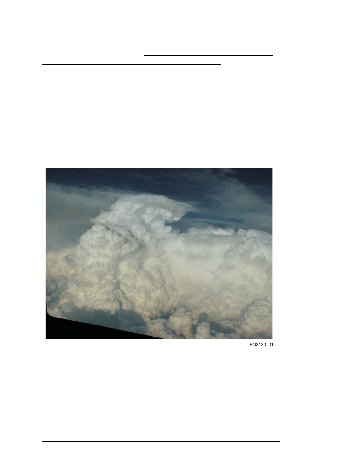
THUNDERSTORM REFLECTIVITY
Understanding thunderstorm reflectivity is the key to understanding how
MultiScan works. In general, thunderstorm reflectivity can be divided
into three parts (see figure 3-1).
Figure 3-1 Thunderstorm Reflectivity Levels
The bottom third of the storm below the freezing level is composed
entirely of water and is the part of the storm that most efficiently
reflects radar energy. The middle third of the storm is composed of a
combination of supercooled water and ice crystals. Reflectivity in this
part o f the storm begins to diminish due to the fact that ice crystals
1st Edition, 1st Revision
18 Sep 03 3-1
THEORY OF OPERATION COLLINS
Thunderstorm Reflectivity MultiScan™ Radar
are very poor radar reflectors. The to p third of the storm is composed
entirely of ice crystals and is al most invisible to radar. In addition, a
growing thunderstorm may have a turbulence bow wave above the
visible portion of the storm (♦page 5-5).
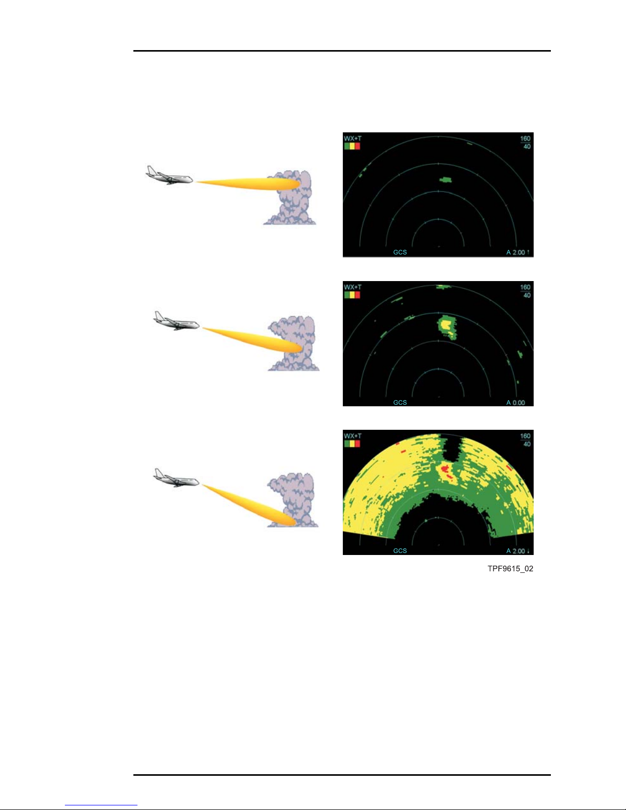
Figure 3-2 shows an actual thunderstorm. The pictures in figure 3-3
show the corresponding radar picture as tilt is increased. In practice,
finding the proper tilt angle during manual operation often becomes
a compromise between observing the most reflective part of the
thunderstorm and reducing ground clutter returns (♦page 4-61, ♦page
5-6).
Figure 3-2 Observed Thunderstorm
1st Edition, 1st Revision
3-2 18 Sep 03
COLLINS THEORY OF OPERATION
MultiScan™ Radar Thunderstorm Reflectivity
Figure 3-3 Observed Thunderstorm and Corresponding Radar
Display at Varying Tilt Settings
1st Edition, 1st Revision
18 Sep 03 3-3
THEORY OF OPERATION COLLINS
The Ideal Radar Beam MultiScan™ Radar
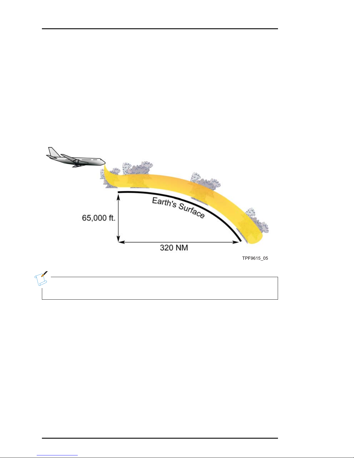
THE IDEAL RADAR BEAM
Understanding thunderstorm reflectivity and the effect that radar tilt
angle has on it allows us to envision a hypothetical ideal radar be am
for weather threat detection. The ideal radar beam would look directly
below the aircraft to detect building thunderstorms and then follow the
curvature of the earth out to the radar’s maximum range (figure 3-4).
Thus, the ideal beam would keep the reflective part of all significant
weather in view at all times, from right at the aircraft out to 320 NM.
Figure 3-4 Ideal Radar Beam
N
NOTE
Note that the earth’s curvature causes a drop of approximately
65,000 feet over a distance of 320 nautical miles.
1st Edition, 1st Revision
3-4 18 Sep 03
 Loading...