

Page 1
Installation Instructions
Y-Series Brushless Servo Motor
Catalog Number Y-1002-1, Y-1002-2, Y-1003-1, Y-1003-2, Y-2006-1, Y-2006-2,
Y-2012-1, Y-2012-2, and Y-3023-2
These installation instructions describe how to install the Y-Series
motors. Use this document if you are responsible for designing,
installing, or troubleshooting the Allen-Bradley Y-Series motor
products. Read all instructions before installing this motor.
For: See Page
Important User Information 2
Receiving and Maintenance Information 3
Motor Catalog Number Identification 3
Before You Install the Motor 4
Using Couplings and Pulleys 5
Preventing Electrical Noise 6
Building and Installing Cables 7
Installing Your Motor 8
Guidelines for Installation 9
Mounting Dimensions 10
Connector Data 13
Motor Load Force Ratings 14
Radial Load and Axial Load Force Ratings 15
Cables and Connector Kits 15
Publication 1398-IN518A-EN-P — January 2001
Page 2
2 Y-Series Motor Installation Instructions
WARNING
IMPORTANT
ATTENTION
SHOCK HAZARD
BURN HAZARD
Important User Information
Solid state equipment has operational characteristics differing from those of electromechanical equipment.
Safety Guidelines for the Application, Installation and Maintenance of Solid State Controls, publication
SGI-1.1
, is available from your local Rockwell Automation sales office or online at
http://literature.rockwellautomation.com
equipment and hard-wired electromechanical devices. Because of this difference, and also because of the
wide variety of uses for solid state equipment, all persons responsible for applying this equipment must
satisfy themselves that each intended application of this equipment is acceptable.
In no event will Rockwell Automation, Inc. be responsible or liable for indirect or consequential damages
resulting from the use or application of this equipment.
The examples and diagrams in this manual are included solely for illustrative purposes. Because of the many
variables and requirements associated with any particular installation, Rockwell Automation, Inc. cannot
assume responsibility or liability for actual use based on the examples and diagrams.
No patent liability is assumed by Rockwell Automation, Inc. with respect to use of information, circuits,
equipment, or software described in this manual.
Reproduction of the contents of this manual, in whole or in part, without written permission of Rockwell
Automation, Inc., is prohibited.
Throughout this manual, when necessary, we use notes to make you aware of safety considerations.
Identifies information about practices or circumstances that can cause an explosion in
a hazardous environment, which may lead to personal injury or death, property
damage, or economic loss.
) describes some important differences between solid state
Publication 1398-IN518A-EN-P — January 2001
Identifies information that is critical for successful application and understanding of
the product.
Identifies information about practices or circumstances that can lead to personal injury
or death, property damage, or economic loss. Attentions help you identify a hazard,
avoid a hazard and recognize the consequences.
Labels may be on or inside the equipment, for example, a drive or motor, to alert
people that dangerous voltage may be present.
Labels may be on or inside the equipment, for example, a drive or motor, to alert
people that surfaces may reach dangerous temperatures.
Page 3
Y-Series Motor Installation Instructions 3
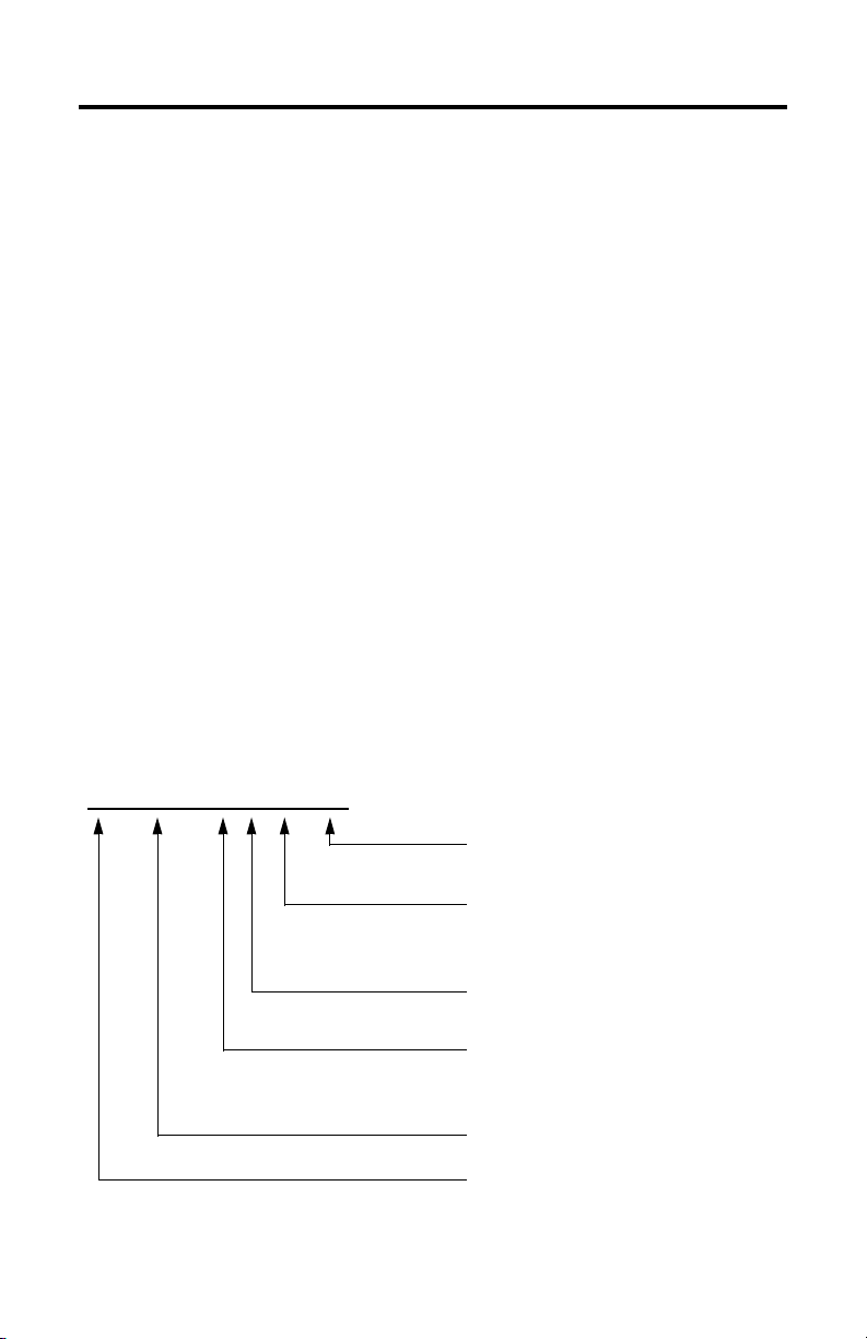
Y - 2006 - 2 H 00 AA
Receiving and Maintenance Information
The customer is responsible for inspecting the equipment before
accepting the shipment from the freight company. Check the item(s)
you receive against your purchase order.
Maintain your motor within the following environmental conditions:
• in a clean, dry location
• within the operating temperature range, 0° to 40° C (32° to 104°
F)
• within the storage temperature range, -30° to 70° C (-22° to 158°
F)
• within the relative humidity range, 5% to 95% non-condensing
• in an non-corrosive atmosphere
Motor Catalog Number Identification
FACTORY DESIGNATED OPTIONS
AA Standard
OPTIONS
00 Standard
04 24V dc Brake
OPTICAL ENCODER LINE COUNT
H 2000 Standard
MOTOR WINDING Ke DESIGNATOR
1 115V ac
2 230V ac
FRAME SIZE
SERIES DESIGNATOR
Y Light Industrial
Publication 1398-IN518A-EN-P — January 2001
Page 4
4 Y-Series Motor Installation Instructions
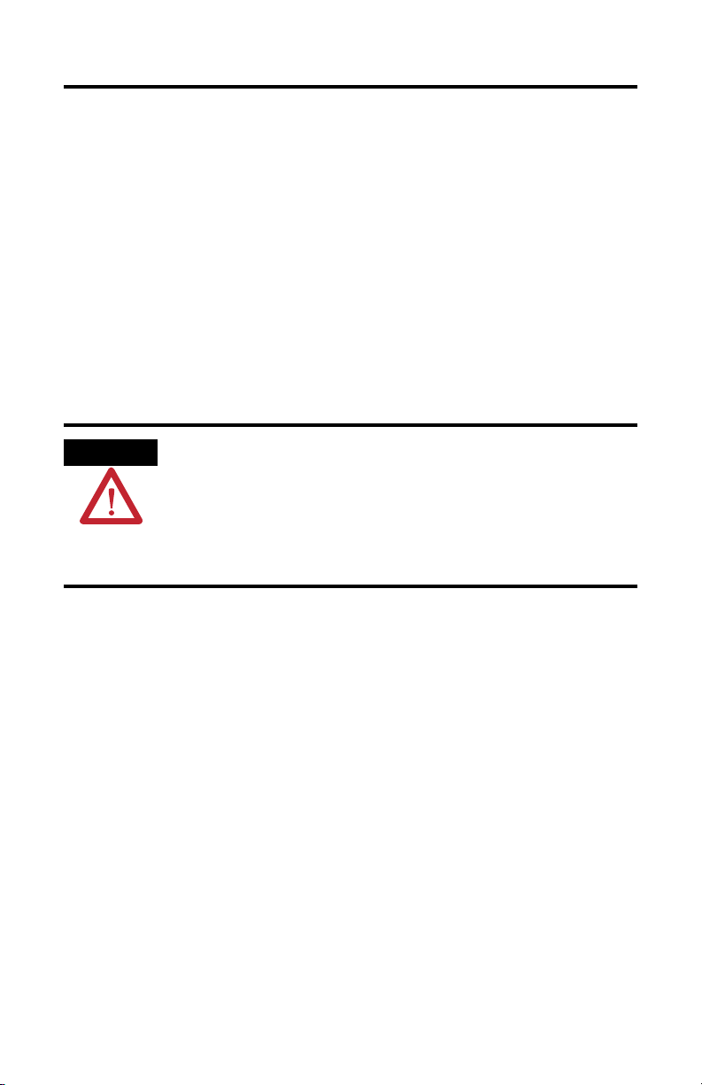
ATTENTION
Before You Install the Motor
Before installing or storing the motor:
1. Remove the motor carefully from its shipping container.
2. Visually inspect the motor for any damage.
3. Examine the motor frame, front output shaft, and mounting pilot
for any defects.
4. Notify the carrier of any shipping damage immediately.
Do not open or attempt to open the motor.
Only a qualified Allen-Bradley employee can
service this type of motor
Failure to observe these safety procedures could
result in the equipment being damaged.
Publication 1398-IN518A-EN-P — January 2001
Page 5

Y-Series Motor Installation Instructions 5
Using Couplings and Pulleys
Mechanical connections to the motor shaft, such as couplings and
pulleys, require a torsionally rigid coupling or a reinforced timing
belt. The high dynamic performance of servo motors can cause
couplings, pulleys or belts to loosen or slip over time. A loose or
slipping connection will cause system instability and may damage
the motor shaft. All connections between the system and the servo
motor shaft must be rigid to achieve acceptable response from the
system. Periodically inspect connections to verify their rigidity.
When mounting couplings or pulleys to the motor shaft, ensure that
the connections are properly aligned and that axial and radial loads
are within the specifications of the motor.
Force Ratings on page 14 for guidelines on how to achieve 20,000
hours of motor bearing life.
Refer to Motor Load
Publication 1398-IN518A-EN-P — January 2001
Page 6

6 Y-Series Motor Installation Instructions
Preventing Electrical Noise
ElectroMagnetic Interference (EMI), commonly called noise, may
adversely impact motor performance by inducing stray signals.
Effective techniques to counter EMI include filtering the AC power,
shielding and separating signal carrying lines, and practicing good
grounding techniques.
Effective AC power filtering can be achieved by using isolated AC
power transformers or properly installed AC line filters.
To help avoid EMI:
1. Physically separate signal lines from motor cabling and power
wiring. Do not route signal wires with motor and power wires, or
over the vent openings of servo drives.
2. Ground all equipment using a single-point parallel ground system
that employs ground bus bars or large straps. If necessary, use
additional electrical noise reduction techniques to reduce EMI in
noisy environments.
Publication 1398-IN518A-EN-P — January 2001
Page 7

Y-Series Motor Installation Instructions 7
ATTENTION
Building and Installing Cables
Knowledgeable cable routing and careful cable construction
improves system ElectroMagnetic Compatibility (EMC).
To build and install cables, perform the following steps:
1. Keep wire lengths as short as physically possible.
2. Route signal cables (encoder, serial, analog) away from motor
and power wiring.
3. Separate cables by 0.3 m (1 ft) minimum for every 9 m (30 ft) of
parallel run.
4. Ground both ends of the encoder cable shield and twist the signal
wire pairs to prevent electromagnetic interference (EMI) from
other equipment.
High voltage can be present on the shield of a
power cable, if the shield is not grounded.
Ensure there is a connection to ground for any
power cable shield.
Failure to observe these safety procedures could
result in personal injury or damage to equipment.
Publication 1398-IN518A-EN-P — January 2001
Page 8

8 Y-Series Motor Installation Instructions
ATTENTION
Installing Your Motor
Y-2006, Y-2012, and Y-3023 motors include a mounting pilot for
aligning the motor on a machine. Preferred fasteners are stainless
steel. The installation must comply with all local regulations and use
of equipment and installation practices that promote
electromagnetic compatibility (EMC) and safety.
Unmounted motors, disconnected mechanical
couplings, and/or disconnected cables are
dangerous if power is applied.
Disassembled equipment should be appropriately
identified (tagged-out) and access to electrical
power restricted (locked-out).
Failure to observe these safety procedures could
result in personal injury
Publication 1398-IN518A-EN-P — January 2001
Page 9

Y-Series Motor Installation Instructions 9
ATTENTION
Guidelines for Installation
Observe the following for installing the motor.
1. Allow sufficient clearances in the area of the motor for it to stay
within its specified operating temperature range.
Receiving and Maintenance Information on page 3 for operating
range. Do not enclose the motor unless forced air is blown across
the motor for cooling. A fan blowing air across the motor will
improve its performance. Keep other heat producing devices
away from the motor.
2. Refer to Mounting Dimensions on page 10 to determine the
mounting dimensions of your motor.
3. Place the motor with connectors pointing downward.
4. Properly mount and align the motor.
5. Attach all power and encoder cables after the motor is mounted
and use a drip loop in the cable to keep liquids flowing away
from the connectors.
Refer to
Outer surfaces of motor can reach high
temperatures, 100° C (212° F) during motor
operation.
Take precautions to prevent accidental contact with
hot surfaces. Consider motor surface temperature
when selecting motor mating connections and
cables.
Failure to observe these safety procedures could
result in personal injury or damage to equipment.
Publication 1398-IN518A-EN-P — January 2001
Page 10

10 Y-Series Motor Installation Instructions
L AH
BE
BB
Cable length for all motors:
1000 mm (39.37 in.)
U
AB
P
AK
BF = DIA. HOLES
AJ = DIA. BOLT CIRCLE
L
(Y-3023 only)
EP
BP
(Y-3023 only)
Mounting Dimensions
The dimension symbols and actual dimensions of the different
models in the Y-Series are referenced in a table on the next page.
Figure 1
Reference for Mounting Dimensions
Publication 1398-IN518A-EN-P — January 2001
Page 11

Y-Series Motor Installation Instructions 11
Dimension 1
(Refer to drawing)
Motor
Y-1002 Y-1003 Y-2006 Y-2012 Y-3023
AB mm 30 30 41 41 52
(in.) (1.2) (1.2) (1.6) (1.6) (2.0)
AH mm 25 25 30 30 40
(in.) (1.0) (1.0) (1.2) (1.2) (1.6)
AJ mm 46 46 70 70 90
(in.) (1.8) (1.8) (2.8) (2.8) (3.5)
AK mm 30 30 50 50 70
(in.) (1.2) (1.2) (2.0) (2.0) (2.8)
BB mm 2.5 2.5 3.0 3.0 3.0
(in.) (0.10) (0.10) (0.12) (0.12) (0.12)
BE mm 5 5 6 6 8
(in.) (0.2) (0.2) (0.24) (0.24) (0.3)
BF mm 4.5 4.5 5.5 5.5 6.6
(in.) (0.18) (0.18) (0.22) (0.22) (0.26)
BP (3023 only) mm — — — — 2
(in.) — — — — (0.8)
EP (3023 only) mm — — — — 19.5
(in.) — — — — (0.77)
L mm 70 88 95.5 123.5 140
(in.) (2.8) (3.5) (3.8) (4.9) (5.5)
L with Brake mm 108.5 126.5 133.5 161.5 180.5
(in.) (4.27) (4.98) (5.26) (6.36) (7.11)
P mm 40 40 60 60 80
(in.) (1.6) (1.6) (2.4) (2.4) (3.1)
U mm 8 8 14 14 16
(in.) (0.3) (0.3) (0.5) (0.5) (0.6)
Publication 1398-IN518A-EN-P — January 2001
Page 12

12 Y-Series Motor Installation Instructions
Dimension 1
(Refer to drawing)
Shaft End Hole
Motor
Y-1002 Y-1003 Y-2006 Y-2012 Y-3023
mm — — M5 x 0.8 M5 x 0.8 M5 x 0.8
Thread
Shaft End Hole
Thread Depth
mm — — 12 12 12
(in.) — — (0.5) (0.5) (0.5)
Tolerances AH mm ±0.8 ±0.8 ±0.8 ±0.8 ±0.8
(in.) (±0.315) (±0.315) (±0.315) (±0.315) (±0.315)
AK mm -0.021 -0.021 -0.025 -0.025 -0.030
(in.) (-0.0008) (-0.0008) (-0.0009) (-0.0009) (-0.0011)
L mm ±1.0 ±1.0 ±1.0 ±1.0 ±1.0
(in.) (±0.4) (±0.4) (±0.4) (±0.4) (±0.4)
U mm -0.009 -0.009 -0.011 -0.011 -0.011
(in.) (-0.0003) (-0.0003) (-0.0004) (-0.0004) (-0.0004)
Cab
±100 mm (±4.0 in.)
le
1
Y-S erie s motors are designed to metric dimensions. Inch measurements are mathematical conversions.
Publication 1398-IN518A-EN-P — January 2001
Page 13

Y-Series Motor Installation Instructions 13
3
21
4 5 6
7 8
9
1
21 25
2826
3
4 8
9
14
2015
Connector Data
The tables below list the signal descriptions for the encoder and
power connector pins.
Encoder Connector Power Connector
Pin Signal Pin Signal
1 - 8, 25-28 Open 1
9 A+ 2
10 A- 3
11 B+ 4 Open
12 B- 5 Ground
13 I+ 6 Open
14 I- 7
15 HALL A+ 8 Open
16 HALL A- 9
17 HALL B+
18 HALL B19 HALL C+
20 HALL C21 Open
22 +5 VDC
23
24
1
+5V COM not connected to motor case ground.
2
Cable Shield connected to motor case ground.
COM 1
Shield 2
Phase R 1
Phase S 1
Phase T 1
Brake+ 2
Brake- 2
1
Cables and drives may label the R, S and T
power phases as U, V and W respectively.
2
Open on non-brake motors.
Power housing: AMP 206705-2
Y-1002/Y-1003 contacts: AMP 66102-8
Y-2006/Y-2012 contacts: AMP 66098-8
Y-3023 contacts: AMP 66098-8
Encoder housing: AMP 206152-1
Encoder contacts: AMP 3-66507-0
Publication 1398-IN518A-EN-P — January 2001
Page 14

14 Y-Series Motor Installation Instructions
Axial load force (F)
AF
Radial load force (FR)
Radial load force (FR) applied to shaft at 2AF/3.
Motor Load Force Ratings
Motors are capable of operating with sustained maximum radial or
maximum axial shaft loads. The measurement points for maximum
radial and axial load forces are shown in the figure below.
Figure 2
Load Forces on Shaft
The following table represents load factors that provide a 20,000
hour L10 bearing fatigue life for Y-Series motors. These load factors
do not account for possible application-specific life reduction factors
that may occur, such as bearing grease contamination from external
sources.
Publication 1398-IN518A-EN-P — January 2001
Page 15

Y-Series Motor Installation Instructions 15
Radial Load and Axial Load Force Ratings
Motor Maximum Radial (FR) Load Maximum Axial (F) Load
with a Radial Load
kg (lb) kg (lb)
Y-1002 10 (22) 3 (6.6)
Y-1003 10 (22) 3 (6.6)
Y-2006 20 (44) 8 (17.6)
Y-2012 25 (55) 10 (22.0)
Y-3023 35 (77) 20 (44.0)
Cables and Connector Kits
Factory manufactured cables are available in standard cable lengths.
They can provide environmental sealing and shield termination. The
following cables are for connecting the Y-Series motors.
Catalog Number Description
9106-0066 Connector Kit
(kit includes connector, pins and backshell for
both the power and encoder connectors)
Publication 1398-IN518A-EN-P — January 2001
Page 16

Rockwell Automation Support
Rockwell Automation provides technical information on the Web to assist you in
using its products. At http://support.rockwellautomation.com
technical manuals, a knowledge base of FAQs, technical and application notes,
sample code and links to software service packs, and a MySupport feature that you
can customize to make the best use of these tools.
For an additional level of technical phone support for installation, configuration and
troubleshooting, we offer TechConnect support programs. For more information,
contact your local distributor or Rockwell Automation representative, or visit
http://support.rockwellautomation.com
.
Installation Assistance
If you experience a problem within the first 24 hours of installation, please review
the information that's contained in this manual. You can also contact a special
Customer Support number for initial help in getting your product up and running.
, you can find
United States 1.440.646.3434
Outside United States Please contact your local Rockwell Automation representative for any technical
Monday – Friday, 8 a.m. – 5 p.m. EST
support issues.
New Product Satisfaction Return
Rockwell Automation tests all of its products to ensure that they are fully
operational when shipped from the manufacturing facility. However, if your
product is not functioning and needs to be returned, follow these procedures.
United States Contact your distributor. You must provide a Customer Support case number (call the
phone number above to obtain one) to your distributor in order to complete the return
process.
Outside United States Please contact your local Rockwell Automation representative for the return
procedure.
Allen-Bradley, Kinetix, Rockwell Automation, MP-Series, and TechConnect are trademarks of Rockwell Automation, Inc.
Trademarks not belonging to Rockwell Automation are property of their respective companies.
Publication 1398-IN518A-EN-P — January 2001 0013-1064-001 Rev B
Supersedes Publication 1398-5.8 April 1999 Copyright © Year Rockwell Automation, Inc. All rights reserved. Printed in the U.S.A.
 Loading...