

Page 1

WebPakCS Software
Ver sion 1.0
Instruction Manual
D2-3447
Page 2

The information in this manual is subject to change without notice.
Trademarks not belonging to Rockwell Automation are property
of their respective companies.
Throughout this manual, the following notes are used to alert you to safety considerations:
ATTENTION:Identifies information about practices or circumstances that can lead to personal
injury or death, property damage, or economic loss.
!
Important: Identifies information that is critical for successful application and understanding of the product.
ATTENTION:Only qualified electrical personnel familiar with the construction and operation of
this equipment and the hazards involved should install, operate, or service this equipment. Read
!
and understand this manual and other applicable manuals in their entirety before proceeding.
Failure to observe this precaution could result in severe bodily injury or loss of life.
ATTENTION:Only qualified personnel should develop or change drive configuration. Read and
understand the drive hardware and software instruction manuals in their entirety before
proceeding with the configuration edit function. Failure to observe this precaution could result in
severe bodily injury or loss of life.
ATTENTION:Parameter assignments made while the software in controlling and communicating
to the drive overwrite the parameter values in the drive. Read and understand this manual and
all other applicable manuals in their entirety before changing drive parameter values. Failure to
observe this precaution could result in severe bodily injury or loss of life.
IBM is a trademark of International Business Machine Corporation.
Microsoft, Windows, and MS-DOS are trademarks of Microsoft Corporation.
Pentium is a trademark of Intel Corporation.
WebPak, WebPakCS, and Reliance are trademarks of Rockwell Automation.
© 2000 Rockwell International Corporation
Page 3

Chapter 1 Introduction
1.1 About the WebPakCS Software ................................... ....... ...... ....... ...... .........1-1
1.2 Software Requirements................................... ....... ...... ....... ............................1-1
1.3 Hardware Requirements.................................................................................. 1-2
1.4 Cables .............................................................................................................1-2
1.5 Safety Information ...........................................................................................1-3
1.6 Purpose of This Manual................................................................................... 1-3
1.7 Intended Audience........................................................................................... 1-3
1.8 Terms Used in This Manual............................................................................. 1-4
1.9 Where to Find Additional Information..............................................................1-4
Chapter 2 Getting Started
2.1 Installing the WebPakCS Software on a Personal Computer.......................... 2-1
2.2 Setting Up Communication Between the WebPakCS Software and the Drive 2-2
2.2.1 Connecting the Personal Computer’s Serial Port to the Drive..............2-2
2.2.2 Setting Up the Drive to Communicate with the Personal Computer......2-3
2.2.3 Selecting the Correct Communication Port........................................... 2-4
2.3 Starting the Software .......................................................................................2-4
2.4 About the Menus and Toolbars ........................................... ...... ....... ...............2- 4
2.4.1 About the Menus................................................ ....... ...... ....... ...... ....... .. 2-5
2.4.2 About the Toolbar .. ....... ...... ...... ....... ...... ................................................ 2-5
2.5 Exiting the WebPakCS Software..................................................................... 2-6
CONTENTS
Chapter 3 Configuring the Drive
3.1 Selecting an Application Type.........................................................................3-1
3.2 Creating a New Configuration .........................................................................3-2
3.3 Opening a Drive Configuration File .................................................................3-3
3.4 Editing a Configuration ........... ...... ...... ....... ...... ....... ...... ....... ...... ......................3-4
3.4.1 Example Configuration Setup/Edit Window...........................................3-4
3.4.2 Application Edit Left View Operations................................................... 3-5
3.4.3 Application Edit Right View Operations.................................................3-5
3.4.4 Ending an Editing Session .................................................................... 3-5
3.5 Saving a Drive Configuration.............. ....... ...... ................................................ 3-5
3.6 Saving the Open Drive Configuration to Another File...................................... 3-6
3.7 Printing a Configuration ...................................................................................3-7
Chapter 4 Uploading and Downloading Drive Configurations
4.1 Uploading a Drive Configuration......................................................................4-1
4.2 Downloading a Configuration to the Drive.......................................................4-2
4.3 Comparing the Drive Configuration to the Opened Configuration...................4-2
Chapter 5 Monitoring and Editing Drive Parameters
5.1 About the Parameter Monitor .......................... ....... ...... ....... ...... ....... ...............5-1
5.2 Adding Parameters to the Monitor List ............................................................5-3
5.3 Removing Parameters from the Monitor List...................................................5-3
5.4 Assigning Values to Parameters in the Drive .................................................. 5-4
5.5 Saving a Monitor List .......................................................................................5-6
Contents
I
Page 4

5.6 Displaying a Monitor List..................................................................................5-7
5.7 Exiting the WebPakCS Parameter Monitor......................................................5-7
Chapter 6 Monitoring Drive Status and Alarms
6.1 Displaying and Clearing the Fault Log and Alarm Log.....................................6-1
6.2 Restoring Default Values to Drive Parameters ................................................6-3
6.3 Saving Drive Parameter Values to Non-Volatile Memory on the Drive............6-3
6.4 Restoring Drive Parameter Values from Non-Volatile Memory in the Drive.....6-3
Chapter 7 Controlling the Drive
7.1 Controlling a Drive............................................................................................7-1
7.2 Selecting the Control Source ...........................................................................7-2
7.3 Setting the Line Speed Reference...................................................................7-3
7.4 Setting the Jog Reference................................................................................7-3
7.5 Starting and Stopping the Drive.......................................................................7-4
7.6 Monitoring Drive Indicators ..............................................................................7-4
Chapter 8 Using PC Scope
8.1 About PC Scope..................... ....... ...... ...... ....... ...... ....... ................................... 8-1
8.2 Setting Up a Trace ...........................................................................................8-4
8.2.1 Specifying Signals .................................................................................8-5
8.2.2 Setting Up Data Sampling .....................................................................8-5
8.2.3 Setting Up the Trigger............................................................................8-6
8.3 Acquiring a Trace.............................................................................................8-7
8.4 Working with the Cursors........................................................... ...... ....... ...... ...8-8
8.4.1 Moving a Cursor ....................................................................................8-9
8.4.2 Specifying the Cursors To Track Each Other........................................8-9
8.5 Changing Views ...............................................................................................8-9
8.5.1 Turning Cursors On and Off ..................................................................8-9
8.5.2 Turning Grids On and Off......................................................................8-9
8.5.3 Magnifying the Trace Display ..............................................................8-10
8.6 Taking a Trace Snapshot...............................................................................8-10
8.6.1 Taking a Snapshot...............................................................................8-10
8.6.2 Choosing the Trace Snapshot Colors..................................................8-11
8.7 Saving a Trace File ........................................................................................8-11
8.8 Clearing the Trace Display and Setup ...........................................................8-12
8.9 Opening a Trace File......................................................................................8-12
8.10 Closing PC Scope..........................................................................................8-13
Chapter 9 Troubleshooting
9.1 Using Error Messages......................................................................................9-1
9.2 Getting Assistance from Reliance Electric.......................................................9-1
Index ...........................................................................................................................Index-1
II
WebPakCS Software V1.0
Page 5

List of Figures
Figure 2.1 – RS-232 Cable Connector Pinouts for Drives with a 25-Pin Connector. 2-2
Figure 2.2 – Sample Main Window for an Established Connection..........................2-4
Figure 2.3 – Graphical Tool Bar................................................................................ 2-5
Figure 3.1 – Example of Configuration Setup and Edit View....................................3-2
Figure 3.2 – Open Configuration File Dialog Box.....................................................3-3
Figure 3.3 – Example of a Configuration Setup/Edit Window...................................3-4
Figure 3.4 – Save Configuration Dialog Box............................................................. 3-6
Figure 3.5 – Sample Configuration File Printout.......................................................3-7
Figure 5.1 – Parameter Monitor Window.................................................................. 5-2
Figure 5.2 – Add Parameters to Monitor List Dialog Box..........................................5-3
Figure 5.3 – Save Monitor List Dialog Box ............................................................... 5-6
Figure 5.4 – Recall Monitor List Dialog Box.............................................................. 5-7
Figure 6.1 – Sample Fault Log List Box.................................................................... 6-1
Figure 6.2 – Sample Alarm Log List Box..................................................................6-2
Figure 7.1 – Drive Control Window...........................................................................7-2
Figure 8.1 – The PC Scope Screen..........................................................................8-2
Figure 8.2 – Trace Signal Setup Dialog Box.............................................................8-4
Figure 8.3 – Sample Trace .......................................................................................8-8
Figure 8.4 – Save a Signal Trace File Dialog Box.................................................. 8-11
Figure 8.5 – Open Signal Trace File Dialog Box ....................................................8-12
Contents
III
Page 6

IV
WebPakCS Software V1.0
Page 7

List of Tables
Table 1.1 – Cables.................................................................................................... 1-2
Table 1.2 – Terms.....................................................................................................1-4
Table 2.1 – Overview of the Menu............................................................................2-4
Table 2.2 – Toolbar Icons and Menus......................................................................2-5
Table 6.1 – Using the Fault and Alarm Logs ............................................................ 6-2
Table 8.1 – PC Scope Toolbar Buttons....................................................................8-3
Contents
V
Page 8

VI
WebPakCS Software V1.0
Page 9

This section describes the computer requirements for the WebPakCS™ software and
presents general information about the software and this manual.
1.1 About the WebPakCS Software
Use the WebPakCS software to help you develop drive configurations on your
personal computer for WebPak
communicates with the drive through the personal computer’s RS-232 port.
Using the WebPakCS software, you can:
• Create, modify and store WebPak drive configurations.
• Download and upload configurations to or from a WebPak drive.
• Display and change parameters in the drive.
• Control and monitor the drive.
™ 3000 drives. The WebPakCS software
CHAPTER 1
Introduction
• View waveforms in the drive.
• Read and reset the drive fault and error log.
• Send Memory Sav e , Memory Restore and Restore Defaults commands to a drive.
• Print a drive configuration on a printer or to a text file.
1.2 Software Requirements
The WebPakCS software requires Microsoft Windows 9x or later versions (including
Windows NT) and Internet Explorer version 5.0 or later. Make sure these programs
are installed and configured on your personal computer before attempting to install the
WebPakCS software.
Introduction
1-1
Page 10

1.3 Hardware Requirements
Before installing and using the WebP akCS software, make sure you have the following
hardware:
• An IBM or IBM-compatible 486 or Pentium personal computer running
Windows 9x or Windows NT
• 16 Mbytes of RAM (minimum)
• A hard drive with at least 1 Mbytes free space available for the WebPakCS
software
• A CD-ROM drive
• A monochrome or color monitor: VGA or better
• An RS-232 serial COM port for communicating with the drive
• An RS-232 serial cable with:
• A 25-pin or 9-pin D-shell connector for your personal computer
• A 25-pin male D-shell connector for the drive
The WebPak 3000 drive is equipped with a terminal strip as well as a 9-pin D-shell
connector. Either one can be used to connect to the personal computer. Refer to
section 2.2.1 for additional information.
1.4 Cables
This table lists the cables you can use to connect a personal computer to the drive.
Table 1.1 – Cables
Cable M/N Type Purpose
61C127 Interface cable, 9-pin to 25-pin directly connects the personal computer to the drive
2CA3000 Interface cable, 9-pin to 9-pin use with adapter cable 2CA3001
2CA3001 Adapter cable,9-pin to 25-pin connects a 9-pin COM port on the personal computer
to the drive via the M/N 2CA3000 Interface cable
1-2
WebPakCS Software V1.0
Page 11

1.5 Safety Information
ATTENTION:Do not run other Windows or DOS software applications
while you are using the WebPakCS software for drive control.
!
The WebPakCS software operates as a Windows 95 application. It cannot preempt
other applications or functions in Windows and, therefore, cannot guarantee a
response time to user input actions. Using other applications while controlling a drive
with the WebPakCS software can tie up PC resources and cause drive commands to
be delayed.
To prevent drive commands (run, stop, and jog) from unexpectedly executing, the
WebPakCS software specifies a time-out period (approximately 2 seconds) when it
establishes a link with the drive. While the link is established, the WebPakCS software
sends messages to the drive to validate the link. If a message fails to reach the drive
within the time-out period because program execution has been delayed, the drive
invalidates the link. If the link becomes invalid, the drive does not accept drive
commands. If the drive was running, it stops, and a serial fault is generated.
Before a drive control command is sent to the drive, the drive’s status is checked to
validate the link. If communication between the WebPakCS software and the drive
have been interrupted and you have selected a drive command, the command is not
sent and a message is displayed.
Unexpected machine motion could result. Failure to observe this
precaution could result in severe bodily injury or loss of life.
The time-out period is also used by the Parameter Monitor and Download functions,
both of which could be running while the Drive Control Window is open. If the link
becomes invalid while these functions are running, a message will be displayed in the
Drive Control window before the link is re-established. When you select the Download
command while the Drive Control window is open, you cannot execute drive command
controls until the download is complete.
1.6 Purpose of This Manual
This manual describes how to use the WebPakCS software to configure WebPak
3000 drives. Refer to the WebPak 3000 Software Reference instruction manual for
information about parameters.
1.7 Intended Au dience
This manual is written for those who must install the WebPakCS software and use the
software to configure and run WebPak 3000 drives. This manual assumes you are
familiar with Windows and makes references to it throughout.
You will need to know the basic Windows functions before using the WebPakCS
software.
Introduction
1-3
Page 12

1.8 Terms Used in This Manual
The following terms are used throughout this manual:
Table 1.2 – Terms
Term Definition
WebPakCS software The software used to configure, monitor, and operate
the WebPak 3000 drive.
CD-ROM drive The personal computer’s CD-ROM drive.
COM port Communication port.
configuration file Drive configurations stored on the personal computer
that can only be read and written to by the WebPakCS
software.
drive The Power Module and regulator combination that
controls a motor.
Drives can be configured using the WebPakCS
software.
drive configuration The set of drive parameters and assignment values
that specify how the drive runs.
hard drive The personal computer’s hard disk drive.
opened configuration The configuration that is active in the WebPakCS
software.
1.9 Where to Find Additional Information
See the following instruction manuals for more information about the drives that can
be configured using the WebPakCS software:
• D2-3443 WebPak 3000 DC Drive Hardware Reference, Installation, and
Troubleshooting
• D2-3444 WebPak 3000 DC Drive Software Reference Manual
• D2-3345 WebPak 3000 Operator Interface Module (OIM) User Guide
• D2-3446 WebPak 3000 DC Drive Application Workbook
1-4
WebPakCS Software V1.0
Page 13

CHAPTER 2
Getting Started
This section describes how to install the WebPakCS software and use the menus and
toolbars.
2.1 Installing the WebPakCS Software on a Personal
Computer
All files needed to install the WebPakCS software are on the WebPakCS CD-ROM
disk. Use the following steps to install the WebPakCS software.
Important: To exit installation, select Cancel from any screen or press .
Step 1. Start Microsoft Windows.
Step 2. Insert the WebPakCS software disk into the CD-ROM drive.
Step 3. From the Start Menu, select Run.
Step 4. In the Open field, type in the drive letter followed by SETUP. For example, if
your CD-ROM drive is D:, you would type D:SETUP
Follow the screen prompts.
Step 5. At the Choose Destination Location window, specify the location where you
want to install the software. The location defaults to
C:\Program Files\Rockwell Automation\WebPakCS
Select OK when the drive and directory are correct. The installation software
automatically creates the new path.
Step 6. At the prompt “Enter desired default location for WebPakCS work files,”
specify the location where you want to store the drive configuration files. The
default location is C:\WebPakCS_Work. Select OK when the drive and
directory are correct.
The program begins its installation sequence.
After creating the program group and icon, the WebPakCS software installation is
complete. The installation program automatically exits, and you return to Windows.
You should see a new entry in your Windows Start | Programs menu titled
“WebPakCS.”
Step 7. Remove the WebPakCS disk from the CD-ROM drive.
The WebPakCS software is now installed and ready to use.
Getting Started
2-1
Page 14

2.2 Setting Up Communication Betwee n the WebPakCS
Software and the Drive
The following sections describe the setup required for communication between the
WebPakCS software and the drive. To enable communication between the
WebPakCS software and the drive:
• Physically connect the personal computer to the drive through a serial port
connection (see section 2.2.1)
• Set up the drive for communication through a serial port (see section 2.2.2)
• Select the correct communication port on the personal computer (see section
2.2.3)
2.2.1 Connecting the Personal Computer’s Serial Port to the Drive
For the WebPakCS software to communicate with the drive, connect the personal
computer to the drive using an appropriate cable by following these instructions:
Step 1. The drive’s RS-232 port uses a 25-pin male D-shell connector. Connect the
communication cable’s 25-pin male connector to the drive. Refer to the drive
instruction manual for the location of the RS-232 port on the drive.
Step 2. Connect the other end of the communication cable to the personal
computer’s COM1 port. If the COM1 port is not available, refer to section
2.2.3 for information about selecting the correct communication port. The
personal computer COM port might have either a 25-pin or a 9-pin connector .
Refer to figure 2.1 for cable connector and pinout signals for 9-pin and 25-pin
.
configurations.
2-2
Personal Computer
25-pin Female
Data OUT
Data IN
Ground
Person al Com pute r
9-pin Female
Data OUT
Data IN
Ground
Figure 2.1 – RS-232 Cable Connector Pinouts for Drives with a 25-Pin Connector
- 3
- 2
- 7
- 3
- 2
- 5
Drive
25-pin Male
3 -
Data IN
2 -
Data OUT
7 -
Ground
Drive
25-pin Male
3 -
Data IN
2 -
Data OUT
7 -
Ground
WebPakCS Software V1.0
Page 15

2.2.2 Setting Up the Drive to Communicate with the Personal Computer
For the WebPakCS software to communicate with the drive, the drive’s operation
control source parameter must be set up properly. Set parameter P.000 to specify
serial communication. Refer to the WebPak 3000 Software Reference manual for
more information.
2.2.3 Selecting the Correct Communication Port
The WebPakCS software communicates with the drive through the personal
computer’s serial port. The software defaults to the COM1 port. If COM1 is already
being used, you must select another COM port. To change the COM port:
Step 1. Start the WebPakCS software.
Step 2. From the Options menu, select COM.
Step 3. Select the appropriate COM port from the options displayed in the dialog box.
Step 4. Select OK when the correct COM port is selected. This returns you to the
WebPakCS main window.
2.3 Starting the Software
Follow this procedure to start the WebPakCS software.
Step 1. From the Start menu, choose Programs | WebPakCS.
Step 2. Select an application type by one of the following methods:
• From the File menu, select Application T ype, or from the toolbar, click .
Then select the application type from the list box. (To build a configuration
using all of the parameters, select Generic as the application type.)
• From the File menu, select Open, or from the toolbar, click . Then
select a configuration file using the Open dialog box.
• From the Config menu, select Upload. The current drive configuration will
be uploaded.
2.4 About the Menus and Toolbars
Use the menus and toolbar to navigate through the software as described in the
following sections. Figure 2.2 shows the WebPakCS Main Window. The main window
contains the main menu, toolbar, status bar, and two views separated by a splitter bar.
Getting Started
2-3
Page 16
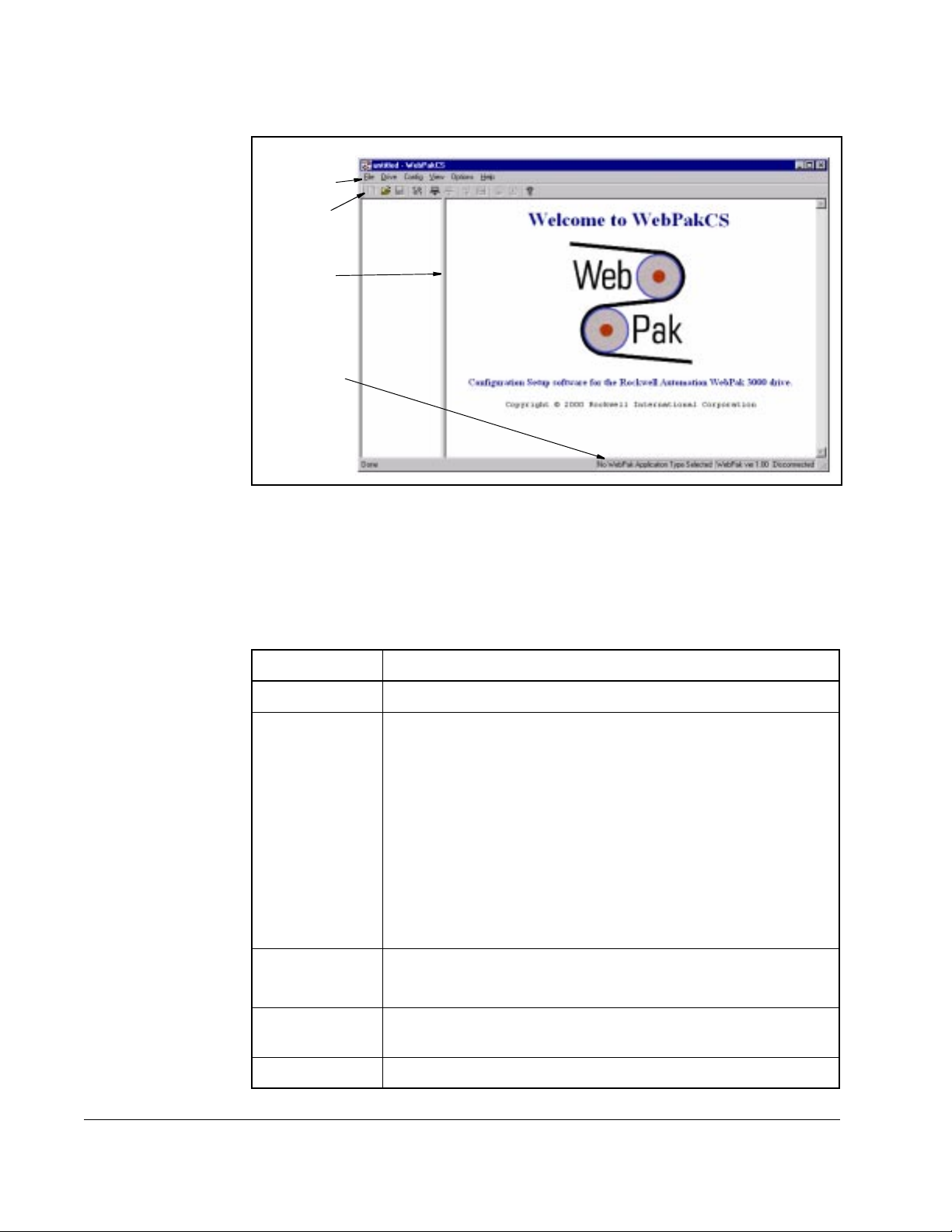
.
Main Menu
Toolbar
Splitter Bar
Status Bar
Figure 2.2 – Sample Main Window for an Established Connection
2.4.1 About the Menus
Table 2.1 explains the WebPakCS software functions you can access through the
menus.
Table 2.1 – Overview of the Menu
Use this menu: To:
File Access application types and edit configuration files
Drive • Connect to and disconnect from the drive
• Control the drive
• View drive status and alarms
• Use the PC Scope
• Set parameters in the drive to the default values
• Save drive parameter values to the drive’s non-volatile
memory
• Restore values from the drive’s non-volatile memory to its
run-time memory
Config • Upload or download a configuration file
• Compare a configuration file
Option Choose the COM port on the personal computer which is being
used to connect to the drive.
2-4
Help Access the online help.
WebPakCS Software V1.0
Page 17
2.4.2 About the Toolbar
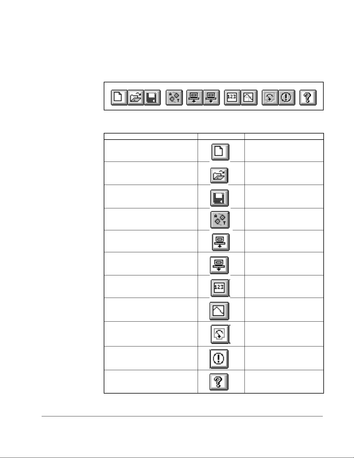
A graphical tool bar, displayed below the main menu in the main window, provides a
shortcut method for ex ecuting commonly-used main menu functions. Figure 2.3 shows
the toolbar, and table 2.2 lists the functions represented by each icon.
To: Use this icon: Or this menu command:
Create a new configuration file. File | New
Open a configuration file. File | Open
Save a configuration file. File | Save
Figure 2.3 – Graphical Tool Bar
Table 2.2 – Toolbar Icons and Menus
Select an application type File | Application type
Upload a configuration file from a
Config | Upload
drive.
Download a configuration file to a
Config | Download
drive.
Monitor drive parameters. Drive | Parameter Monitor
Access the PC Scope. Drive | PC Scope
Control the drive. Drive | Control
Display the drive’s fault and alarm
Drive | Fault/alarm
logs.
Access the on-line help. Help | Contents
Getting Started
2-5
Page 18

2.5 Exiting the WebPakCS Software
To exit the software, choose Exit from the File menu. Exit closes the WebPakCS
software. If you modified the open configuration, you are prompted to save the
changes to a configuration file.
2-6
WebPakCS Software V1.0
Page 19

Configuring the Drive
This chapter describes how to configure a WebPak 3000 drive.
3.1 Selecting an Application Type
The WebPak 3000 drive can be configured for nine different application types: eight
named applications and Generic. The application types are as follows:
• Constant Diameter Speed Regulator
• Variable Diameter Speed Regulator
• Constant Diameter Current Regulator
• Variable Diameter Current Regulator
• Constant Diameter Position Regulator
• Variable Diameter Position Regulator
• Constant Diameter Tension Regulator
• Variable Diameter Tension Regulator
• Generic
CHAPTER 3
To select an application type:
Step 1. From the File menu, select Application Type, or from the toolbar, click .
Step 2. A list box will be displayed. When you select an application type, the
application edit view is reset to the first screen in the application edit
sequence.
The application type you select determines which screens are displayed in the
Configuration Setup and Edit view (see figure 3.1). The named application types will
show only the parameters that are pertinent to that application type. If a specific
application type cannot be determined during file open or drive connect, then the
application type defaults to Generic.
The Generic application type is used to display screens which are not tailored toward
any particular application. The generic application screens make all input parameters
available for editing.
Configuring the Drive
3-1
Page 20
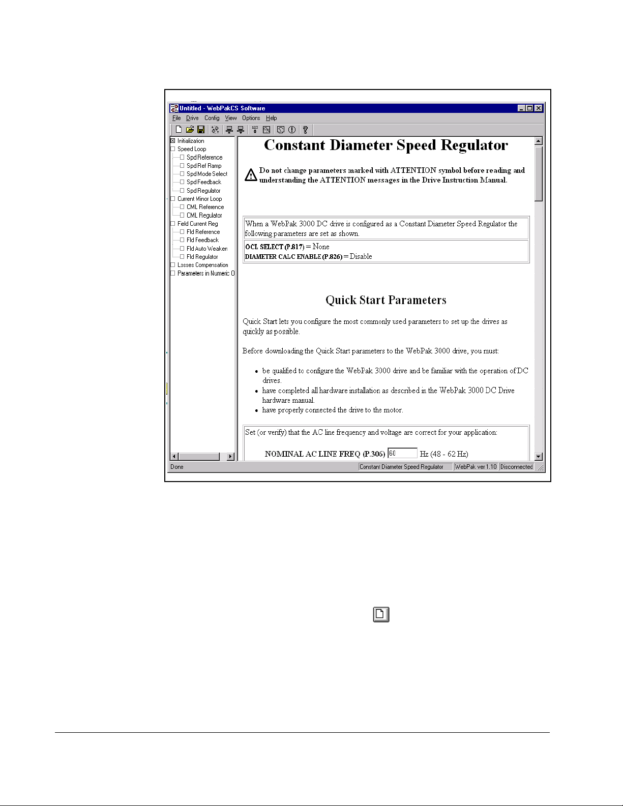
Figure 3.1 – Example of Configuration Setup and Edit View
3.2 Creating a New Configuration
You can create a new drive configuration, which sets the parameter values to their
defaults for the selected application. You assign a name to the configuration file when
you save it. See sections 3.5 and 3.6 for information about saving configurations.
To create a new configuration:
• From the File menu, choose New, or click .
If a configuration file is already open and has been changed, a dialog box is displayed
that asks if you want to save the current configuration file. If you select Yes, the Save
As dialog box is displayed before the new configuration file is opened.
When you select an application type, parameters that depend on the control type are
changed to their defaults. The control type determines which parameters are
displayed.
3-2
WebPakCS Software V1.0
Page 21

3.3 Opening a Drive Configuration File
Opening a drive configuration file loads the file from the personal computer to the
WebPakCS software. Once the configuration file is opened, you can download it to the
drive.
To open a configuration file:
Step 1. From the File menu, choose Open, or click .
Step 2. If you already have a configuration file open and have made edits to it that
have not been saved, you are prompted to save the changes. Make the
appropriate selection. See section 3.6 for more information about saving
configuration files.
The Open dialog box is displayed. An example is shown in figure 3.2.
Configuring the Drive
Figure 3.2 – Open Configuration File Dialog Box
Step 3. The Open dialog box defaults to the work directory of the WebPakCS
software, which was specified during installation. If this is not the correct
directory, select the directory where the file is stored.
Step 4. Select the name of the file you want to open. The name of the file should be
copied in the File Name box. If not, click on it again.
If the configuration file you want does not have the .wpc extension, it does not
show up automatically in the box under File Name. In this case, select *.* in
the List Files of Type box to display all of the available files in the File Name
list.
Step 5. Open the file by selecting OK. The name of the file you selected now appears
in the Opened Configuration field of the main window.
To close the dialog box without selecting a file, select Cancel.
3-3
Page 22

3.4 Editing a Configuration
Use the Configuration Setup and Edit function to create and edit drive configurations.
It provides drive application-specific entry and edit features. The Configuration Setup/
Edit window contains a combination of help information and user entry fields.
The setup and edit function provides the capability for you to move either sequentially
through all screens or to move directly to a portion of a previously completed setup for
the purpose of changing it.
You can move sequentially through the edit screens or move directly to a specific
screen by selecting it in the tree control list which is displayed in the left view. When
you select a section of the configuration, the appropriate setup window is displayed in
the right view. The tree control list contains only entries that are pertinent to the
particul ar dri ve applicat ion .
3.4.1 Example Configuration Setup/Edit Window
When the Setup/Edit window is opened, the application type you select determines
which Setup/Edit windows are displayed. If you open an existing configuration file, the
software will determine the application type based on the values of a set of "footprint"
parameters in the configuration file. If the configuration satisfies more than one
application footprint, then the application type will default to Generic.
Figure 3.3 shows an example of a Configuration Setup/Edit window.
3-4
Figure 3.3 – Example of a Configuration Setup/Edit Window
WebPakCS Software V1.0
Page 23

3.4.2 Application Edit Left View Operations
The left view contains a tree list of available right-view screens. The tree list in the left
view may or may not have collapsible nodes depending on the number of right-view
screens needed for applications. If there are collapsible nodes, then the operations in
the left view are as follows:
• Double-click on a collapsed node in the tree list to expand the node.
• Double-click on an expanded node in the tree list to collapse the node.
• Click on a node or leaf in the tree list to display the Setup/Edit window for the
selected area of the configuration.
3.4.3 Application Edit Right View Operations
Parameter entry fields consist of edit controls and combo boxes.
3.4.4 Ending an Editing Session
When you have finished editing parameters:
• Use the Save command from the File menu to save the edited configuration file to
disk.
or
• Use the Download command to write the edited configuration file to the drive.
If you select Cancel from the Configuration Editor, a message is displayed prompting
you to ignore the changes or accept them. If you ignore the changes, any new
parameter values entered during the editing session are ignored, and the session
ends.
3.5 Saving a Drive Configuration
Saving a file writes the open drive configuration to the configuration file that is shown
in the main window. This writes over the configuration file shown in the main window.
To save a file:
• From the File menu, choose Save, or click .
If the configuration file is “Untitled” or “Untitiled Upload,” the Save Configuration File
dialog box is displayed. Refer to section 3.6 for more information.
Configuring the Drive
3-5
Page 24

3.6 Saving the Open Drive Configuration to Another File
You can write the open drive configuration to a configuration file other than the one
shown in the main window. To do this:
Step 1. From the File menu, choose Save As. The Save Configuration File dialog box
is displayed, as shown in figure 3.4.
Figure 3.4 – Save Configuration Dialog Box
Step 2. Select the disk drive and directory where you want to store the configuration.
Selecting Network lets you access any mapped network drive.
Step 3. Specify the file name in the File Name field. Configuration file names must be
eight alphanumeric characters or fewer. The file name should have the
extension .wpc.
Step 4. Select OK to save the file. Select Cancel to close the dialog box without
saving.
3-6
WebPakCS Software V1.0
Page 25

3.7 Printing a Configuration
You can send a copy of the open configuration to a printer or to a text file. The printout
lists the configuration parameters and their assigned values.
To print a configuration:
Step 1. From the left view, select WebPak Parameters - Numerical Order.
Step 2. Click anywhere on the right view.
Step 3. From the File menu, choose Print, or click .
The standard Windows Print dialog box is displayed.
Figure 3.5 shows part of an sample printout.
Configuring the Drive
Figure 3.5 – Sample Configuration File Printout
3-7
Page 26

3-8
WebPakCS Software V1.0
Page 27

Uploading and Downloading Drive
This chapter describes how to upload, download, and compare drive configurations.
4.1 Uploading a Drive Configuration
You can upload the drive configuration from the connected drive to the personal
computer.
To upload a configuration:
Step 1. Make sure the personal computer is connected to the drive. Refer to sections
2.2 and 3.1 if you need instructions for connecting the personal computer to a
drive.
Step 2. From the Config menu, choose Upload or click .
CHAPTER 4
Configurations
Step 3. If a drive configuration is already opened, you are prompted to save that
configuration to a file. The open configuration (if any) is replaced by the
uploaded drive configuration.
After uploading the drive configuration, the open configuration is displayed as
“UNTITLED UPLOAD.”
Uploading and Downloading Drive Configurations
4-1
Page 28

4.2 Downloading a Configuration to the Drive
You can copy the opened configuration currently in the WebPakCS software to the
connected drive.
ATTENTION:The download command replaces the parameter values in
the drive with the parameter values from the open configuration. Only
!
Important: If WebPak 3000 parameter changes are disabled by the drive’s Program
To download an opened configuration to the connected drive, follow these steps:
Step 1. Make sure the personal computer is connected to the drive. Refer to sections
Step 2. Make sure the drive is stopped before downloading a configuration to the
Step 3. From the Config menu, choose Download, or click .
qualified personnel should develop and download drive configurations.
Read and understand the drive instruction manuals in their entirety
before downloading a configuration. Failure to observe this precaution
could result in severe bodily injury or loss of life.
Protection jumper (J16), you cannot write parameters to the drive.
2.2 and 3.1 if you need instructions for connecting the personal computer to a
drive.
drive.
Step 4. If the downloaded configuration contains parameter values that are out of
range for the drive, the software on the drive modifies these parameter
values to bring them within allowed ranges. If this occurs, a message box
asking if you want to do a Config Compare is displayed. This dialog box
displays the differences between the downloaded configuration and the
configuration currently in the drive.
4.3 Comparing the Drive Configuration to the Opened
Configuration
You can compare all of the parameter values in the opened configuration with the
parameter values in the drive. To compare the parameters in an open configuration
with those on the drive, follow these steps:
Step 1. Make sure the personal computer is connected to the drive. Refer to sections
2.2 and 3.1 if you need instructions for connecting the personal computer to a
drive.
Step 2. From the Config menu, choose Compare Drive.
4-2
WebPakCS Software V1.0
Page 29

Monitoring and Editing Drive
This chapter describes how to monitor and edit parameters using the Parameter
Monitor.
5.1 About the Parameter Monitor
Use the Parameter Monitor to view and edit parameter values in the connected drive.
You can also set up monitor lists to store your choices for future use. The Parameter
Monitor is not affected by and does not affect the opened configuration.
Important: If WebPak 3000 parameter changes are disabled by the drive’s Program
Protection jumper (J16), you cannot write parameters to the drive.
You cannot change parameter values in the opened configuration using the Parameter
Monitor. To copy changes made in Monitor into the opened configuration, you must
upload the drive configuration from the drive (refer to chapter 4).
CHAPTER 5
Parameters
To access the Parameter Monitor, choose Parameter Monitor from the Drive menu, or
click .
The first time you access the Par ameter Monitor, the window is blank. Use the Add,
Remove, Assign, and Save buttons at the top of the window to create a parameter list
that can be saved for future use. See the following sections for information about using
these functions.
When parameters are displayed in the Parameter Monitor window, the parameter
values are updated periodically from the drive.
Monitoring and Editing Drive Parameters
5-1
Page 30

You can select a parameter shown in the Monitor window by clicking the parameter
name, or by using PgUp, PgDn, and the arrow keys. The Remove and Assign
functions work on the selected parameter. Figure 5.1 shows an example of the
Parameter Monitor window.
Figure 5.1 – Parameter Monitor Window
The sections that follow describe the functions available when using the WebPakCS
Parameter Monitor function.
5-2
WebPakCS Software V1.0
Page 31

5.2 Adding Parameters to the Monitor List
You can add up to 20 parameters to the Monitor List. When you select Add, the Add
Parameters to Monitor List dialog box is displayed. The Sort By options let you display
the parameters by parameter number or by description (alphabetically). Figure 5.2
shows a sample Add Parameters to Monitor List dialog box.
Figure 5.2 – Add Parameters to Monitor List Dialog Box
To add parameters, follow these steps:
Step 1. Use the scroll bar or the arrow keys to move up and down the list of
parameters.
Step 2. Use the mouse or the spacebar to select the parameters you want to monitor.
You can select multiple parameters before choosing Add. You can select a
total of 20 parameters.
Step 3. Do one of the following:
• To add the parameters to the monitor list and continue to display the
dialog box, select Add.
• To add the parameters and return to the monitor window, select OK.
5.3 Removing Parame te rs from the Monitor List
To delete parameters from the Monitor List, follow these steps:
Step 1. Select the parameter you want to remove from the list.
Step 2. Click on the Remove button.
Important: You can clear all the parameters from a Monitor List by selecting Clear.
Monitoring and Editing Drive Parameters
5-3
Page 32

5.4 Assigning Values to Parameters in the Drive
The Assign button assigns a value to the selected parameter. The assigned value is
displayed on the Parameter List screen and can be sent to the drive.
Important: The Assign function is available only when you are connected to a drive.
You cannot assign parameter values unless you are connected to a drive.
If you are not connected to a drive, the parameter list displays “???” for all
parameter values.
When the drive is running, new values can be assigned only to tunable parameters.
For configurable parameters, the drive must be stopped before new values can be
assigned. Refer to the appropriate drive instruction manual to determine which
parameters are tunable.
When you select Assign or double-click on the parameters, a Parameter Assignment
dialog box is displayed. The options in this dialog box depend on the options for the
parameter.
5-4
WebPakCS Software V1.0
Page 33

If the parameter: The dialog box looks like this: Do the following:
can be set to any
value within a range
Enter the value in the box or
change the value by using the
scroll bar.
has limited options Click the arrow and select from
the options.
can be set through
the options or by
selecting a value
within a range
Click the arrow and select from
the options, or enter the value in
the box.
To send the new parameter value to the drive, choose the Send button. Send does not
exit the parameter Assignment dialog box, so you can continue to make adjustments
to the value of the selected parameter and monitor the effect on the drive.
When you have finished making adjustments to the value of a parameter, select OK to
send the parameter value to the drive and exit the Parameter Assign dialog box.
If you select Cancel, the parameter value that appears in the Parameter Assign dialog
box is ignored and the Parameter Assign dialog box is closed.
Monitoring and Editing Drive Parameters
5-5
Page 34

5.5 Saving a Monitor List
The Save command creates a file containing the list of parameter numbers you have
displayed in the parameter monitor. When you select Save, the Save Monitor List
dialog box is displayed as shown in figure 5.3.
To save a monitor list file, follow these steps:
Step 1. Select the drive and directory for the monitor list file.
Step 2. Enter a file name. The file name should include the extension .MON.
Step 3. Save the monitor list by selecting OK, or select Cancel to exit the dialog box
without saving.
5-6
Figure 5.3 – Save Monitor List Dialog Box
WebPakCS Software V1.0
Page 35

5.6 Displaying a Monitor List
To display a previously saved monitor list in the WebPakCS Parameter Monitor
screen, use the Recall button. The monitor list file must have been created and saved.
Any parameters currently being displayed in the Parameter Monitor are replaced by
the list of parameters read in from the monitor list file. Figure 5.4 shows the Recall
Monitor List dialog box.
Figure 5.4 – Recall Monitor List Dialog Box
Use the following steps to read and display a Monitor List file:
Step 1. Select the drive and directory path that contains the monitor list files.
Step 2. If the monitor list files were saved using a file extension other than .MON,
select *.* in the List Files of Type box to display all of the files.
Step 3. Enter a file name, or select the file name from the displayed list.
Step 4. To recall the file and display it in the Parameter Monitor window, select OK.
To close the dialog box without recalling the monitor list file, select Cancel.
5.7 Exiting the WebPakCS Parameter Monitor
To exit the monitor list and return to the WebPakCS main window, choose the Close
command from the WebPakCS Parameter Monitor window. If a parameter list is
displayed in Parameter Monitor and it has not been saved to a file, you are prompted
to save the list. See section 5.5 for inf ormation about saving monitor list files.
Monitoring and Editing Drive Parameters
5-7
Page 36

5-8
WebPakCS Software V1.0
Page 37

CHAPTER 6
Monitoring Drive Status and Alarms
This section describes how to monitor drive status indicators and alarms.
6.1 Displaying and Clearing the Fault Log and Alarm Log
You can display fault or alarm logs to help you troubleshoot problems.
To upload the fault log or alarm log from the drive, follow these steps:
Step 1. Make sure the personal computer is connected to the drive. Refer to chapters
2 and 3 for instructions about connecting the personal computer to a drive.
Step 2. From the Drive menu, choose Fault/alarm, or click .
The fault or alarm number, description, and time stamp is displayed in the list box. The
displayed log is updated about once a second with any new alarm or fault information.
Figure 6.1 shows a sample fault log while figure 6.2 shows a sample alarm log.
Monitoring Drive Status and Alarms
Figure 6.1 – Sample Fault Log List Box
6-1
Page 38

Figure 6.2 – Sample Alarm Log List Box
To switch between the fault and alarm list boxes, select the appropriate option for Log
Select.
The time stamp displays the time when the fault or alarm occurred. This time is from
the drive memory. See the WebPak 3000 OIM User Guide (D2-3445) for information
about the time stamp.
Table 6.1 describes how you can use the logs.
Table 6.1 – Using the Fault and Alarm Logs
To: Do the following:
Clear the fault or alarm log Select Clear.
The logged faults or alarms are deleted
from the log. This command clears only
the log that is currently displayed. Clear
does not reset drive faults or eliminate the
cause of the alarms; it simply clears the
log.
Reset the drive after a fault Select Stop/Reset in the Drive Control
window.
A reset command will be sent to the drive.
This command will not be available if the
WebPakCS software is not the control
source.
6-2
Exit the log window Select Close.
WebPakCS Software V1.0
Page 39

6.2 Restoring Default Values to Dri ve Parameters
You can restore the default values to all of the drive parameters that have defaults. To
do this:
• From the Drive menu, choose Restore defaults.
6.3 Saving Drive Parameter Values to Non-Volatile
Memory on the Drive
You can save the values of the drive parameters in the drive’s runtime memory to nonvolatile memory on the drive. To do this:
• From the Drive menu, choose Memory save.
6.4 Restoring Drive Parameter Values from Non-Volatile
Memory in the Drive
You can write the values stored by the Memory save command from non-volatile
memory on the drive into the drive’s runtime memory. To do this:
• From the Drive menu, choose Memory restore.
Monitoring Drive Status and Alarms
6-3
Page 40

6-4
WebPakCS Software V1.0
Page 41

CHAPTER 7
Controlling the Drive
This section describes how to control the drive using the WebPakCS software.
7.1 Controlling a Drive
ATTENTION:Only qualified electrical personnel familiar with the
construction and operation of the equipment and the hazards involved
!
Using the Drive Control dialog box, you can control the WebPak 3000 drive by:
• selecting the control source, reference mode, and motor rotation dir ecti on
• setting the drive reference
• starting and stopping the drive
• monitoring the drive indicators
To access the Drive Control dialog box, follow these steps:
Step 1. Make sure the personal computer is connected to the drive. Refer to section
should adjust or operate this equipment. Failure to observe this
precaution could result in severe bodily injury or loss of life.
ATTENTION:Do not run other Windows or DOS software applications
while you are using the WebPakCS software for drive control.
Unexpected machine motion could result. Failure to observe this
precaution could result in severe bodily injury or loss of life.
7.1 for information about establishing communication with the drive.
Controlling the Drive
Step 2. From the Drive menu, choose Control or click .
An Attention message is displayed.
Step 3. Make sure you understand this message, then select OK to display the Drive
Control window. Figure 7.1 shows an example of a Drive Control window.
7-1
Page 42

Figure 7.1 – Drive Control Window
You can also access other WebPakCS software functions while the Drive Control
window is on the screen. The Drive Control window remains open until you close the
window (by selecting the Close button) or exit the WebPakCS software.
The following sections describe how to use the Drive Control window to control a
drive’s functions.
Important: If a running drive that is being controlled by the WebP akCS software loses
communication with the software, a serial fault occurs and the drive stops.
If the running drive is being controlled by its front-panel and
communication with the software is lost, the message “Disconnected”
appears in the main window status bar.
7.2 Selecting the Contr ol Sou rce
You can select one of the following as the control source for the drive:
• Local
• Terminal Strip
•Serial
•Network
7-2
WebPakCS Software V1.0
Page 43

You must select Serial to control the drive using the Drive Control window. If an y other
control source is selected, you can only monitor the drive functions displayed in the
Drive Metering window or reset faults and alarms. All of the other drive commands on
the Drive Control screen are disabled.
7.3 Setting the Line Spee d Reference
The Line Speed Reference box lets you set the drive reference.
Set the line speed reference by:
• moving the scroll bar to change the reference value and automatically send the
value to the drive, or
• entering a new value in the edit box and selecting the Set button to send the
reference value to the drive
7.4 Setting the Jog Referenc e
The Jog Reference box lets you set the jog reference. The valid values are the same
as for the line speed reference. To do this:
Step 1. Click in the Jog reference box and type a new value.
Step 2. Press the Jog Set button.
Controlling the Drive
7-3
Page 44

7.5 Starting and Stopping the Drive
Use the Run, Jog, and Stop/Reset buttons as follows:
To send this command to the drive: Press: Description:
Tension the web Tension On Engages the tension loop. The motor will turn
until slack is out of the web, then wait for
Section Run command.
This control is disabled if the WebPakCS
software is not the control source or if
OCL SELECT (P.817) is set to NONE.
Start Section Run Starts the drive. The motor will ramp up to the
selected line speed reference.
This control is disabled if the WebPakCS
software is not the control source.
Jog forward
Jog reverse
Stop STOP - Section off This control is always enabled, regardless of
Jog Fwd
Jog Rev
The drive will jog while the button is pressed.
Releasing the button sends a stop command
to the drive.
These cont rols ar e di sab led if th e WebPak CS
software is not the control source.
the control source.
7.6 Monitoring Drive Indicators
The Drive Metering box displays five drive indicators for WebPak 3000 drives:
• Selected reference
• Motor speed
• Armature volts
• Motor current
• Percent load
Each drive metering value is displayed as a visual thermometer-type indicator and as
a numeric value. If the numeric value exceeds the range of the indicator, the indicator
moves slightly beyond the far right line in the indic ator gr id .
7-4
WebPakCS Software V1.0
Page 45

This section describes how to use the PC Scope.
8.1 About PC Scope
Use PC Scope to plot drive signals. PC Scope displays the plotted values as a trace.
The type of signals you can acquire depends upon the drive you have connected.
With PC Scope, you can:
• acquire traces of up to two signals at a time
• capture a trace and save it as a snapshot, which you can then compare to a newly
acquired trace
• define a trigger for the traces and specify how much data is gathered and
displayed before the trigger condition
• define a data sampling rate and the number of samples to capture for a given
trace
CHAPTER 8
Using PC Scope
• define a color for each to help you discern traces and trace snapshots
Figure 8.1 shows the PC Scope screen. The screen has its own toolbar and status
window. Table 8.1 explains the PC Scope toolbar buttons.
Using PC Scope
8-1
Page 46

Trace Display Window
Trace aquisition
radio buttons
Tool Bar
T1, T2 position
Aquisition status
Figure 8.1 – The PC Scope Screen
File name
8-2
WebPakCS Software V1.0
Page 47

Table 8.1 – PC Scope Toolbar Buttons
To: Use this button: Or this menu command:
Clear the trace setup, display ,
File | New
and data.
Open a saved trace file. File | Open
Save the currently displayed
File | Save
trace data, set up, and the
snapshots as a trace or ASCII
file.
Open the Trace Signal Setup
Trace | Setup
dialog box.
Zoom the trace display to the
View | Zoom In
area bounded by the cursors.
Redisplay the trace in the
View | Zoom X1
normal view.
Using PC Scope
Turn cursors on or off. View | Cursors
Turn cursor tracking on or off. Cursor | Track
Access the online help. Help
8-3
Page 48

To begin using PC Scope, follow these steps:
Step 1. Set up the trace by clicking and defining the trace information. (See
section 8.2 for more information.)
Step 2. Choose how to acquire the trace data. (See section 8.3 for more information.)
8.2 Setting Up a Trace
Before you can acquire any trace data, you must set up the trace by:
• specifying the signals for the trace(s) (See section 8.2.1.)
• setting up data sampling (See section 8.2.2.)
• setting up the trigger (See section 8.2.3.)
Set up a trace by using the Trace Signal Setup dialog box. To access this dialog box:
• From the Trace menu, choose Setup or click .
Figure 8.2 shows the Trace Signal Setup dialog box.
8-4
Figure 8.2 – Trace Signal Setup Dialog Box
WebPakCS Software V1.0
Page 49

8.2.1 Specifying Signals
Use the Traces group box in the Trace Signal Setup dialog box to specify the signal for
each trace.
To specify a signal, follow these steps:
Step 1. Select the drive signal whose values you want to plot as a trace. The
available signals are determined by the type of drive that is connected.
• Choose the signal or None to be used for Trace A by using the Channel A
list box.
• Choose the signal or None to be used for Trace B by using the Channel B
list box.
Step 2. Choose the type of scale you want to use for each trace.
.
To: Do the following:
Use rounded units per division
values based on the data in the
trace waveform
Specify actual trace vertical axis
minimum and maximum values
Use the scale for Trace A as the
scale for Trace B
8.2.2 S et ting Up Data Sampling
Use the Data sampling group box in the Trace Setup dialog box to define how the
signal data is to be sampled. The settings apply to both traces. To set up data
sampling, follow these steps:
Select the Auto Scale option for the trace you
are defining.
The difference between the minimum and
maximum values in the trace data is
determined from the waveform data, and the
values are rounded up to the next whole
value. For example, a value of 1.763 is
rounded to 2.
The minimum and maximum values are also
set to values beyond the actual values in the
trace waveform data.
Enter the vertical axis minimum and maximum
values in the Min and Max boxes for the trace
you are defining.
Select the option: Use chan A scale.
Using PC Scope
Step 1. Choose how often you want to acquire signal data by choosing a sampling
rate. Choose from 0.5 ms to 10 s.
Step 2. Choose the number of data samples in the trace. Choose a value from 1000
to 100.
Once you select the sample rate and number of samples, the amount of time
for the acquisition is displayed.
8-5
Page 50

8.2.3 S et ting Up the Trigger
Use the Trigger and Trigger delay/position group boxes in the Trace Signal Setup
dialog box to define a trigger that will begin a data acquisition. You do not need to set
up a trigger if you plan to use Auto or Manual to acquire traces. See section 8.3 for
more information.
To set up trigger, follow these steps:
Step 1. Choose a drive signal you want to use as a trigger from the Signal list box.
Step 2. Choose the trigger operation (if desired) that causes the trigger condition by
using the Operation list box. The available trigger operations are determined
by the drive type. Some examples of trigger operations are: less than, greater
than, and equal to.
Step 3. Choose a trigger level that is to be used by the trigger operation. The units
and normalization depend upon the trigger signal.
Step 4. Choose a trigger position or delay by selecting the appropriate option and
entering a value.
To: Choose:
specify how many samples are displayed in the trace before
and after the trigger.
For a trigger position of zero percent, the trigger is at the
beginning of the trace (all samples displayed were acquired
after the trigger). For a trigger position of 100%, the trigger is
at the end of the trace, a position of 50% is in the center, etc.
specify the amount of time between the trigger and the
beginning of data acquisition.
The delay is measured in seconds.
Position
Delay
8-6
WebPakCS Software V1.0
Page 51

8.3 Acquiring a Trace
Once you set up a trace, you must define how the trace is to be acquired. A trace can
be acquired:
• continuously, regardless of a trigger condition
• continuously or once, as specified by a defined trigger
Use the Trace menu or the radio buttons in the toolbar to define how a trace is to be
acquired.
To:
From the Trace menu, choose this
option, or click on this radio button:
Continuously acquire trace data by
sending a manual trigger.
The trigger setup has no effect on the
trace acquisition.
Acquire trace data by sending a
manual trigger to the drive.
The trigger setup has no effect on the
trace acquisition.
Continuously acquire trace data
based on the trigger setup.
After the trace is uploaded and
displayed, the trace acquisition is reenabled, and the cycle starts over.
Trace data is acquired until you
change the trace acquisition
selection.
Acquire a trace based on the trigger
setup.
The trace data is acquired when the
trigger condition has been reached.
Stop a trace acquisition in progress.
If an acquisi tion is no t in pro gre ss, t he
trace display is frozen as it is.
Auto
Manual
Normal
Single
Hold
Using PC Scope
Figure 8.3 illustrates an acquired trace.
8-7
Page 52

T race ma x.
value
Values at
the cursor
Actual data
points
Trace min..
value
V alues at the T cursor location
Figure 8.3 – Sample Trace
8.4 Working with the Cursors
Cursors help you read the value at a specific point on a trace waveform to help you
tune and troubleshoot the drive. PC Scope has two cursor types:
• Y cursors are positioned on a vertical value on the display
• T cursors are positioned on a horizontal or time value
You can read actual data points where the waveform crosses the T cursors. These
values are labeled as@T1 and @T2. Because these are actual data points, you can
use them for calculations. The Y cursor values are based on the scale of the trace
display, so the value is determined by the display resolution and are not as accurate
as the actual data points displayed as the @T1 and @T2 values.
8-8
WebPakCS Software V1.0
Page 53

8.4.1 Moving a Cursor
You can select a cursor by:
• clicking on the cursor label with the mouse
• using the Cursor menu
• using the [Tab] key
Move the cursors by:
• using the up, down, right, and left arrow keys or Shift + arrow key
• clicking on the label with the mouse and dragging the cursor
8.4.2 Specifying the Cursors To Track Each Other
You set the cursors to track together when you move them. This way the cursors can
move left and right and up and down while maintaining the same distance between T1
and T2 or Y1 and Y2.
To set the T and Y cursors so they track together:
• From the Cursor menu, choose Track or click .
Turning track off lets you move the T cursors independently from each other and the Y
cursors independently from each other. Cursor tracking can be turned on and off by
toggling the menu selection or toolbar button.
8.5 Changing Views
You can turn the cursors on and off and magnify the trace display as described in the
following sections.
8.5.1 Turning Cursors On and Off
You can choose to show or not the show the cursors on the trace display.
To turn cursors on or off:
• From the View menu, choose T Cursors or click .
• From the View menu, choose Y Cursors or click .
You cannot use the Zoom feature if the cursors are off.
8.5.2 Turning Grids On and Off
You can choose to show or not the show the grids on the trace display.
To turn grids on or off:
From the View menu, choose Grids.
Using PC Scope
8-9
Page 54

8.5.3 Magnifying the Trace Display
You can magnify the area of the trace display that is bounded by the cursors.
To magnify the display:
• From the View menu, choose Zoom In or click .
To return the display back to the normal view:
• From the View menu, choose Zoom X1 or click .
If you selected the Auto Scale option in the Trace Setup dialog box the PC Scope
scales ten vertical axis to even values. This may result in no change when you zoom
into the trace.
8.6 Taking a Trace Snapshot
You can compare one trace with another by saving trace data and displaying it as a
background for the next trace. This saved trace data is called a snapshot. You can
take a snapshot of either trace A or B or both. Also, you can choose a color to use for
displaying trace snapshots (see section 8.6.2).
8.6.1 Taking a Snapshot
To save a trace and have it displayed as the background for subsequent traces, do the
following:
:
From the Snapshot
To:
Save the current Trace A as a
snapshot.
Save the current Trace B as a
snapshot.
Save both Trace A and Trace
B as snapshots.
Clear the snapshots. Clear The snapshot traces are
menu, choose: Result:
Trace A This trace appears as
the background for the
next Trace A.
Trace B This trace appears as
the background for the
next Trace B.
Trace A & B The traces appear in the
background for the next
traces.
removed from the
background.
8-10
WebPakCS Software V1.0
Page 55

8.6.2 Choosing the Trace Snapshot Colors
You can choose the color that is used to display the snapshots of Trace A or Trace B.
Keep in mind that the trace display window is displayed using the Windows menu
background color, so be careful not to display trace snapshots in the same color, or
the trace will not show up.
To choose a color for a trace snapshot, follow these steps:
Step 1. From the Options menu, choose SnapA Color or SnapB Color.
The color selection dialog box is displayed.
Step 2. Select a standard color or create a custom color and click OK.
Traces can be displayed only in solid colors. If you choose a mixed color, the nearest
solid color is used.
8.7 Saving a Trace File
You can save a trace as either a trace file (.TRC) or an ASCII file (.TRA). Saving a
trace as an ASCII file lets you import the data into another program such as a
spreadsheet program.
Use the Save As command to save the file with a new name. To save a trace file,
follow these steps:
Step 1. From the File menu, choose Save or Save As.
The Save Signal Trace File dialog box is displayed. An example is shown in
.
figure 8.4.
Using PC Scope
Figure 8.4 – Save a Signal Trace File Dialog Box
8-11
Page 56

Step 2. In the File name field, type the name for the file.
Step 3. From the Save as type list box, choose whether you want to save the file as a
Trace file (.TRC) or as an ASCII file (.TRA).
Step 4. From the Save in list box, specify the location where you want to sav e the file.
Step 5. Click OK to save the file.
8.8 Clearing the Trace Display and Setup
You can clear the trace display and setup. To do this:
• From the File menu, choose New or click .
Creating a new trace file deletes any acquired trace data and clears the trace
display.
8.9 Opening a Trace File
You can open a previously saved trace file. To do this, follow these steps:
Step 1. From the File menu, select Open or click .
If you already have a configuration file open and made edits to it that have
not been saved, the software prompts you to save the changes. Make the
appropriate selection. See section 3.5 for more information about saving
configuration files.
The Open Signal Trace File dialog box is displayed. An example is shown in
figure 8.5.
8-12
Figure 8.5 – Open Signal Trace File Dialog Box
WebPakCS Software V1.0
Page 57

Step 2. The Open Signal Trace File dialog box defaults to the working directory of the
WebPakCS software, which was specified during installation. If this is not the
correct directory, select the directory where the file is stored. Select the name
of the file you want to open by double-clicking it with the mouse. The name of
the file should be copied in the File Name box. If not, click it again.
Step 3. Select OK to open the file. To close the dialog box without selecting a file,
select Cancel.
8.10 Closing PC Scope
Close PC Scope by choosing Close from the File menu.
Using PC Scope
8-13
Page 58

8-14
WebPakCS Software V1.0
Page 59

CHAPTER 9
Troubleshooting
This section describes basic troubleshooting information.
9.1 Using Error Messages
An error message might be displayed on the screen while you are using the
WebPakCS software. In most cases, you should be able to correct the error condition
by f ol lo win g t he c ours e of ac tio n de sc ribed by the error mes sage . Ho w e ver, if t he err or
message is preceded by an error number, in the format:
<description>
this case, write down the error and the error number, and contact Reliance Electric.
, this indicates an error that might require assistance to correct. In
9.2 Getting Assistance from Reliance Electric
If you have any questions or problems with the products described in this instruction
manual, contact your local Reliance Electric sales office.
For technical assistance, call 1-800-726-8112.
Error <number>
Troubleshooting
9-1
Page 60

9-2
WebPakCS Software V1.0
Page 61

INDEX
A
About the WebPakCS Software, 1-1
cables, 1-2
exiting the software, 2-6
hardware requirements, 1-2
intended audience, 1-3
menus, 2-4 to 2-5
overview, 1-1
purpose of this manual, 1-3
safety information, 1-3
software requirements, 1-1
starting the software, 2-4
terms used in this manual, 1-4
toolbars, 2-4 to 2-6
where to find additional information, 1-4
Additional information, 1-4
Audience, 1-3
Auto Scale, 8-5
ASCII, 8-11
C
Cables, 1-2
Communication, set up
connecting the serial port, 2-2 to 2-3
selecting the communication port, 2-4
Configuring the Drive
comparing the drive configuration to the
opened configuration, 4-2
creating a new configuration, 3-2
downloading a drive configuration, 4-2
editing a configuration, 3-7 to 3-5
assigning parameter values, 3-4 to 3-5
ending an editing session, 3-5
entering and editing a configuration de-
scription, 3-5 to 3-6
icons, 2-5 to 2-6
opening a drive configuration file, 3-3
printing a configuration, 3-7
saving a drive configuration, 3-5
saving the open drive configuration to another
file, 3-6
selecting an application type, 3-1
uploading a drive configuration, 4-1
Controlling the Drive
controlling a drive, 7-1 to 7-2
icons, 2-5 to 2-6
monitoring drive indicators, 7-4
selecting the control source, 7-2 to 7-3
setting the,
jog reference, 7-3
line speed reference, 7-3
starting and stopping the drive, 7-4
Cursors, 8-8
D
Description
configuration, 3-7
Drive Parameters
adding to monitor list, 5-3
assigning values, 5-4 to 5-5
displaying a monitor list, 5-7
exiting the monitor, 5-7
overview, 5-1 to 5-2
removing from monitor list, 5-3
saving a monitor list, 5-6
E
Editing
a configuration, 3-4 to 3-5
assigning parameter values, 3-4 to 3-5
ending an editing session, 3-5
drive parameters, 5-4 to 5-5
assigning values, 5-5 to 5-6
removing, 5-3
trace file,
acquiring, 8-7
clearing the trace display and setup, 8-12
changing views, 8-9 to 8-10
opening a trace file, 8-12
saving a trace file, 8-11
Error messages, 9-1
G
Getting assistance from Reliance Electric, 9-1
Index
Index-1
Page 62

I
Installation
setting up communication, 2-2 to 2-4
Windows 95/NT, 2-1
moving a cursor, 8-9
specifying the cursors to track each other,
8-9
Printing
drive configuration, 3-7
J
Jog
forward, 7-4
reference, 7-3
reverse, 7-4
M
Monitoring Drive Parameters, 5-1 to 5-7
Monitoring Drive Status and Alarms
displaying and clearing the fault log and alarm
log, 6-1 to 6-3
Menus, 2-4 to 2-5
N
Non-volatile memory, 6-4
P
Parameter Values
adding, 5-3
comparing, 4-3
PC Scope
acquiring a trace, 8-7 to 8-8
clearing the trace display and setup, 8-12
closing the PC Scope, 8-13
changing views, 8-9 to 8-10
icon, 2-6
magnifying the trace display, 8-10
opening a trace file, 8-13
overview, 8-1 to 8-4
saving a trace file, 8-11
setting up a trace, 8-4 to 8-6
specifying signals, 8-5
setting up data sampling, 8-5
setting up the trigger, 8-6
taking a trace snapshot, 8-10
taking a snapshot, 8-10
choosing the trace snapshot colors, 8-11
turning cursors on and off, 8-9
working with cursors, 8-8 to 8-9
R
Restoring,
default values to drive parameters, 6-4
drive parameter values from non-volatile
memory on the drive, 6-4
Requirements
hardware, 1-2
software, 1-1
RS-232, 1-2, 2-2 to 2-3
S
Safety, 1-3
Saving
drive configuration, 3-5, 3-6
drive parameters, 5-5
icon, 2-6
monitor list, 5-6
to another file, 3-6
trace file, 8-11
Section off command, 7-4
Section on command, 7-4
Setup
communication, 2-2 to 2-4
jog reference, 7-3
line speed reference, 7-3
trace, 8-4
windows, 2-1
Snapshot, 8-10
Start command, 7-4
Stop command, 7-4
T
Tension on command, 7-4
Terms used in this manual, 1-4
Toolbars, 2-5 to 2-6, 8-3
Trace files
acquiring, 8-7
clearing the display and setup, 8-12
magnifying, 8-10
opening, 8-12
saving, 8-11
Index-2
WebPakCS Software V1.0
Page 63

setting up, 8-4 to 8-6
specifying signals, 8-5
setting up data sampling, 8-5
setting up the trigger, 8-6
taking a snapshot, 8-10
taking a snapshot, 8-10
choosing the trace snapshot colors, 8-11
Trigger, 8-6
Troubleshooting
getting assistance from Reliance Electric, 9-1
using error messages, 9-1
Z
Zoom, 8-3, 8-10
Index
Index-3
Page 64

Index-4
WebPakCS Software V1.0
Page 65

Page 66

U.S. Drives Technical Support
Tel: (1) 262.512.8176, Fax: (1) 262.512.2222, Email: support@drives.ra.rockwell.com, Online: www.ab.com/support/abdrives
Publication D2-3447-June 2000 Copyright © 2000 Rockwell Automation, Inc. All Rights Reserved. Printed in USA.
 Loading...