

Page 1
CE Filter Kits
for the VSM500 Integrated Driv e/Motor
Model Numbers
VSM-CE-1I, VSM-CE-3I, VSM-CE-1E, and VSM-CE-3E
Instruction Manual D2-3464
ATTENTION:Only qualified personnel familiar with the construction and operation of this
equipment and the hazards involved should install, adjust, operate, and/or service this equipment.
!
Read and understand this instruction manual in its entirety before proceeding. Failure to observe
this precaution could result in severe bodily injury or loss of life.
ATTENTION:The CE filter connects between the incoming AC supply line and the drive input
terminals. The filter must be installed by qualified personnel familiar with the drive and associated
machinery. Failure to observe this precaution could result in bodily injury and/or equipment
damage.
ATTENTION:An incorrectly applied or installed CE filter can result in component damage or a
reduction in product life. Wiring or application errors, such as incorrect wiring layout, incorrect
or inadequate AC supply or excessive ambient temperatures may result in malfunction of the
system. Failure to observe this precaution could result in damage to, or destruction of, equipment.
Product Description
CE filter options are designed to be used with the VSM500 Integrated Drive/Motor. The main function of the CE
filter is to reduce the radio frequency conducted emissions into the main supply lines and ground wiring. This
instruction manual provides the steps needed to install the filter.
Important: Declarations of Conformity (DOC) to the European Union Directives are available for Reliance
Electric AC drive products. Please contact the Rockwell AutoFax service at 216-646-7777 for
copies of the Declaration of Conformity .
Verifying Kit Contents
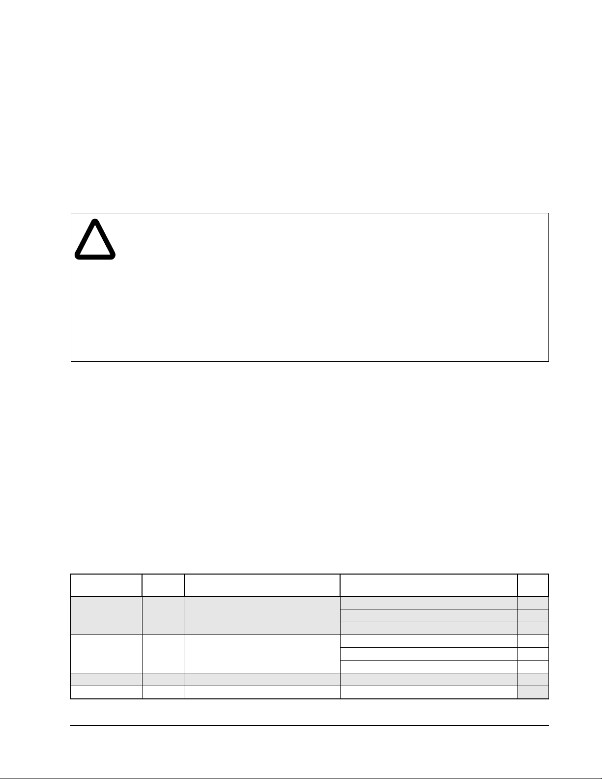
Table 1 lists the available CE filter kits. Verify that your CE filter kit is rated for use with your VSM500 Integrated
Drive/Motor.
Table 1 – CE Filter Kit Contents
Kit Model
Number Version Rating Item Qty
VSM-CE-1I 1.0 115/230 VAC, 1 Ph., 14 A Internal Mount CE Filter 1
M4 x 8 TT Screw 5
M4 Internal Tooth Lock Washer 5
VSM-CE-3I 1.0 230/460 VA C, 3 Ph., 9 A Internal Mount CE Filter 1
M4 x 8 TT Screw 5
M4 Internal Tooth Lock Washer 5
VSM-CE-1E 1.0 115/230 VAC, 1 Ph., 14 A External Mount CE Filter 1
VSM-CE-3E 1.0 230/460 VA C, 3 Ph., 9 A External Mount CE Filter
1
CE Filter Kits for the VSM500 Integrated Drive/Motor
1
Page 2
Installing the Internal Mount CE Filter Kit
ATTENTION:To prevent electrical shock, disconnect the power source before installing or
servicing the unit. Failure to observe these precautions could result in severe bodily injury or loss
!
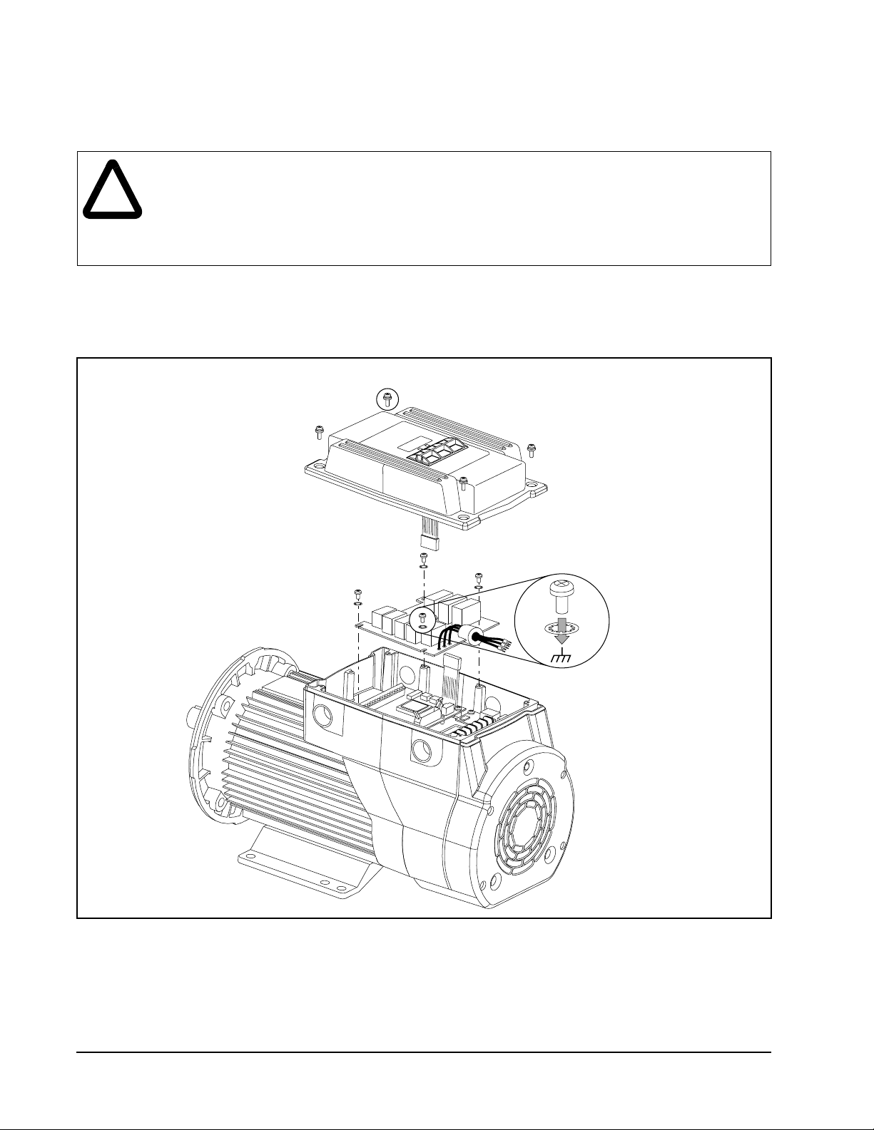
Step 1. Remove the cover of the VSM500 unit by loosening the four cover screws. The display ribbon cable is
Step 2. Mount the CE filter as shown in figure 1 below using the screws and lock washers provided.
of life.
ATTENTION:After disconnecting input power, wait five minutes and check with voltmeter to
assure that DC bus capacitors are discharged. The voltmeter should read zero volts. Failure to
observe these precautions could result in severe bodily injury or loss of life.
designed to disconnect from the main unit when the cover is removed.
1.46 Nm
(13 in-lb)
2.6 Nm
(23 in-lb)
Figure 1 – Mounting the Internal CE Filter Kit
Step 3. Connect the incoming AC supply line to the CE filter as shown in figure 2 and figure 3.
Important: The filter may cause ground leakage currents. Therefore, a solid ground connection must be
provided as shown in figure 2.
2
CE Filter Kits for the VSM500 Integrated Drive/Motor
Page 3
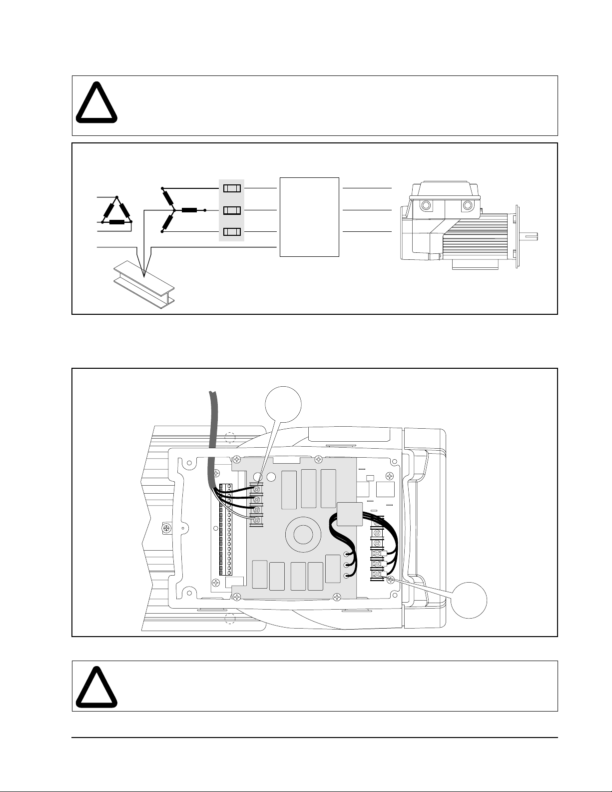
ATTENTION:RFI filters can only be used with AC supplies that are nominally balanced with
respect to ground. In some installations, three-phase supplies are occasionally connected in a
!
3-wire configuration with one phase grounded (Grounded Delta). The filter must not be used in
Grounded Delta supplies. Failure to observe this precaution could result in damage to, or
destruction of, the equipment.
Conduit/4-Wire Cable
L1
IN
L2
IN
L3
IN
PE
Nearest Building Structure Steel
Figure 2 – Wiring the Internal Mount CE Kit
CE Filter
W1
W2
W3
OUT
OUT
OUT
VSM500 Integrated Drive/Motor
R/L1
S/L2
T/L3
Step 4. Connect the power wires from the CE filter to the VSM500 unit as shown in figure 3 (three-phase unit
shown).
1.3 Nm
(12 in-lb)
L1
L2
L3
PE
Figure 3 – Wiring the CE Filter to the VSM500 Drive/Motor
DC+
DCDBR
T/L3
S/L2
R/L1
ATTENTION:The cover screws must be securely tightened in order to properly ground the cover.
Verify that all four cover screws are tight before applying power to the unit. Failure to observe
!
this precaution could result in severe bodily injury or loss of life.
Step 5. Reconnect the display ribbon cable and reinstall the unit cover.
CE Filter Kits for the VSM500 Integrated Drive/Motor
1.3 Nm
(12 in-lb)
3
Page 4
Installing the External Mount CE Filter Kit
ATTENTION:To prevent electrical shock, disconnect the power source before installing or
servicing the unit.
!
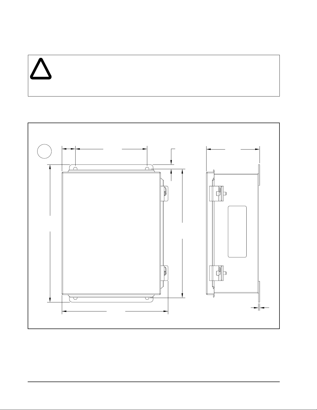
Step 1. Mount the enclosed CE filter as shown in figure 4.
mm
(in)
ATTENTION:The National Codes and standards (NEC, VDE, BSI, etc.) and local codes outline
provisions for safely installing electrical equipment. Installation must comply with specifications
regarding wire types, conductor sizes, branch circuit protection, and disconnect devices. Failure
to do so may result in personal injury and/or equipment damage.
The cable length from the filter to the drive/motor must be less than 3 meters (10 feet).
29.0
(1.13)
152.0
(6.0)
10.0
(0.38)
113.0
(4.46)
292.0
(11.5)
273.0
(10.75)
225.0
(8.87)
3.0
(0.10)
Front View Side View
Figure 4 – Mounting the Enclosed CE Filter
Step 2. Connect the filter between the incoming AC supply line and the drive input terminals as shown in
figure 5 and figure 6.
Important: The filter may cause ground leakage currents. Therefore, a solid ground connection must be
provided as shown in figure 5.
4
CE Filter Kits for the VSM500 Integrated Drive/Motor
Page 5

ATTENTION:RFI filters can only be used with AC supplies that are nominally balanced with
respect to ground. In some installations, three-phase supplies are occasionally connected in a
!
3-wire configuration with one phase grounded (Grounded Delta). The filter must not be used in
Grounded Delta supplies. Failure to observe this precaution could result in damage to, or
destruction of, the equipment.
Conduit/4-Wire Cable
L1
IN
L2
IN
L3
IN
PE
Nearest Building Structure Steel
CE Filter
L1'
L2'
L3'
PE
OUT
OUT
OUT
VSM500 Integrated Drive/Motor
R/L1
S/L2
T/L3
PE
Figure 5 – Wiring the External Mount CE Filter
Step 3. Connect the input power wires to the CE filter as shown in figure 6 (three-phase unit shown).
0.3-0.8 Nm
(3-7 in-lb)
1.3 Nm
(12 in-lb)
Figure 6 – Wiring the Input Power Leads to the CE Filter
CE Filter Kits for the VSM500 Integrated Drive/Motor
L1 L2 L3 PE
IN OUT
Incoming
AC Power
To VSM500 Integrated Drive/Motor
AC Input Terminals
2.8 Nm
(25 in-lb)
5
Page 6

VSM500 Integrated Drive/Motor CE Filter Option Specifications
VSM-CE-1I VSM-CE-3I VSM-CE-1E VSM-CE-3E
Input Voltage 115/230 VAC 230/460 VAC 115/230 VAC 230/460 VAC
Input Phases Single Phase Three Phase Single Phase Three Phase
Frequency 50/60 Hz
Rated Current 14 amps 9 amps 14 amps 9 amps
Power Dissipation 5 watts
Leakage Current (Worst Case) 0.5 mA
Weight 0.33 Kg
(0.73 lb)
0.45 Kg
(0.99 lb)
4.72 Kg
(10.41 lb)
4.89 Kg
(10.78 lb)
Enclosure Internal NEMA 12/IP 65
Operating Temperature 0° to 40°C (32° to 104°F)
Storage Temperature -40° to 85°C (-40° to 185°F)
Relative Humidity 5% to 95%, non-condensing
Vibration 1 G operational, 2.5 G non-operational
Shock 15 G operational, 30 G non-operational
Altitude 1000 meters (3300 feet) without derating. For every 91.4 meters (300 feet)
above 1000 meters, derate current by 1%. Above 3000 meters (10,000 feet),
consult your Reliance Electric Sales Office.
International Standards and
Approvals
D
9
E
6
T
6
S
X
I
L
U
L
®
I
N
Q
D
E
C
T
O
N
UL508C
C
D
9
E
6
T
6
S
X
I
L
U
L
®
I
N
Q
D
E
C
T
O
N
CSA 22.2
EMC Directive 89/336
LV: EN 50178, EN 60204
EMC: EN 61800-3, EN 50081-1, EN 50082-2
Reach us now at www.rockwellautomation.com
Wherever you need us, Rockwell Automation brings together leading
brands in industrial automation including Allen-Bradley controls,
Reliance Electric power transmission products, Dodge mechanical power
transmission components, and Rockwell Software. Rockwell Automation’s
unique, flexible approach to helping customers achieve a competitive
advantage is supported by thousands of authorized partners, distributors
and system integrators around the world.
Americas Headquarters, 1201 South Second Street, Milwaukee, WI 53204, USA, Tel: (1) 414 382-2000, Fax: (1) 414 382 4444
European Headquarters SA/NV, avenue Herrmann Debroux, 46, 1160 Brussels, Belgium, Tel: (32) 2 663 06 00, Fax: (32) 2 663 06 40
Asia Pacific Headquarters, 27/F Citicorp Centre, 18 Whitfield Road, Causeway Bay, Hong Kong, T el: (852) 2887 4788, Fax: (852) 2508 1846
Reliance Electric Standard Drives Business, 24800 Tungsten Road, Cleveland, OH 44117, USA, Tel: (1) 888 374 8370, Fax: (216) 266 7095
Publication D2-3449-1 March 2000 2000 Rockwell International Corporation. All rights reserved. Printed in USA.
Publication D2-3464 - March 2000
2000 Rockwell International Corporation. All rights reserved. Printed in USA.
1999 Rockwell Automation Corporation. All Rights Reserved
Page 7

Page 8

U.S. Drives Technical Support
Tel: (1) 262.512.8176, Fax: (1) 262.512.2222, Email: support@drives.ra.rockwell.com, Online: www.ab.com/support/abdrives
Trademarks not belonging to Rockwell Automation are property of their respective companies.
Publication D2-3464-March 2000 Copyright © 2000 Rockwell Automation, Inc. All Rights Reserved. Printed in USA.
 Loading...