

Page 1

Installing and Operating the
VSM500™ Integrated Drive/Motor
Version 3.0
Instruction Manual
D2-3400-3
Page 2

The information in this manual is subject to change without notice.
Trademarks not belonging to Rockwell Automation are property of their
respective companies.
Throughout this manual, the following notes are used to alert you to safety considerations:
ATTENTION:Identifies information about practices or circumstances that can lead to personal
injury or death, property damage, or economic loss.
!
Important: Identifies information that is critical for successful application and understanding of the product.
The thick black bar shown on the outside margin of this page will be used throughout this instruction manual to
signify new or revised text or figures.
ATTENTION:Only qualified personnel familiar with the construction and operation of this
equipment and the hazards involved should install, adjust, operate, and/or service this equipment.
!
Read and understand this instruction manual in its entirety before proceeding. Failure to observe
this precaution could result in severe bodily injury or loss of life.
ATTENTION:After disconnecting input power, wait five minutes and check with a voltmeter to
insure that DC bus capacitors are discharged. The voltmeter should read zero volts. Failure to
observe this precaution could result in severe bodily injury or loss of life.
ATTENTION:High voltage and rotating parts can cause serious or fatal injury. Installation,
operation, and maintenance of electrical machinery should be performed by qualified personnel.
Make sure that the motor and equipment are grounded and protected in accordance with the
National Electric and local codes. See NEMA MG-2 safety standard.
ATTENTION:The user is responsible for conforming with all applicable local, national, and
international codes. Failure to observe this precaution could result in personal injury and/or
damage to, or destruction of, the equipment.
DeviceNet™ is a trademark of the Open DeviceNet Vendor Association.
VSM500™ and Reliance™ are trademarks of Rockwell Automation.
©2000 Rockwell International Corporation
Page 3

Checklist Installation Checklist
Chapter 1 Step 1 - Identify Your Unit
1.1 VSM500 Standard Unit....................................................................................1-2
1.1.1 Standard Unit Display Description......................................................... 1-2
1.1.2 Standard Unit Reverse LED Description............................................... 1-2
1.1.3 Standard Unit Communications LED Description.................................. 1-3
1.2 VSM500 Local Operator Control Unit.............................................................. 1-3
1.2.1 Local Operator Control Unit Key Descriptions.......................................1-4
1.2.2 Local Operating Control Unit Display Description ................................. 1-4
1.2.3 Local Operating Control Unit Reverse LED Description........................ 1-4
1.2.4 Local Operator Control Unit Communications LED Description............ 1-4
1.2.5 Operating the Unit Using the Local Operator Controls..........................1-5
1.3 Option Kits.......................................................................................................1-5
Chapter 2 Step 2 - Plan the Installation
2.1 Wire Routing Guidelines..................................................................................2-3
2.2 Handling and Lifting Guidelines....................................................................... 2-4
Chapter 3 Step 3 - Mount the Unit
3.1 Mounting Guidelines for Reliance Face-Mounted Motors ...............................3-1
3.2 Mounting Dimensions for NEMA Frames ........................................................ 3-2
C
ONTENTS
Chapter 4 Step 4 - Install External Components
4.1 Installing an AC Input Disconnect....................................................................4-1
4.2 Installing Branch Circuit Protection..................................................................4-1
4.3 Installing Input Isolation Transformers............................................................. 4-2
Chapter 5 Step 5 - Wire AC Power to the Unit and Ground the Unit
5.1 Grounding the Unit .......................................................................................... 5-3
Chapter 6 Step 6 - Install an Emergency Stop
6.1 Compliance with Machinery Safety Standard EN 60204-1: 1992.................... 6-1
Chapter 7 Step 7 - Wire the Control Signal Terminal Block
7.1 Wiring Function Loss .......................................................................................7-4
7.2 Wiring the Analog Output ................................................................................ 7-5
7.3 Wiring the Relay Control Output...................................................................... 7-6
7.4 Wiring RPM or %Load Display ........................................................................ 7-7
7.5 Wiring the Speed Reference ........................................................................... 7-7
7.5.1 Wiring the Preset Speed Inputs ............................................................7-8
7.5.2 Wiring the Speed Reference Signal Potentiometer............................... 7-9
7.5.3 Wiring an External Speed Reference (0 to 10 VDC or 4 to 20 mA) ....7-10
7.6 Wiring Start / Stop Control............................................................................. 7-12
7.7 Wiring Forward / Reverse Control .................................................................7-13
7.8 Wiring Reset Control .....................................................................................7-14
Contents
I
Page 4

Chapter 8 Step 8 - Verify the Setup and Adjust Switches if Required
8.1 Adjusting the Maximum Speed ................. ....... ...... ....... ...................................8-3
8.2 Adjusting the Acceleration / Deceleration Time ...............................................8-4
8.3 Modifying the Setup Using the Setup Slide Switch ..........................................8-5
8.3.1 Power-Up Start (Position 1)...................................................................8-6
8.3.2 Speed Reference Select (Position 2).....................................................8-6
8.3.3 Relay Control Output - Running or Faulted (Position 3) ........................8-7
8.3.4 Auto Restart (Position 4)........................................................................8-7
8.3.5 Torque Curve (Position 5)......................................................................8-8
8.3.6 Stop Type (Position 6) ...........................................................................8-9
8.3.7 Reverse Disable (Position 7).................................................................8-9
8.3.8 Minimum Speed Select (Position 8).......................................................8-9
8.3.9 Start Mode Select (Position 9).............................................................8-11
8.3.10Parameter Mode for DeviceNet Option (Position 10) ..........................8-11
Chapter 9 Step 9 - Check the Installation
9.1 Checking the Installation with the Power Off....................................................9-1
9.2 Checking the Direction of Motor Rotation ........................................................9-2
9.3 Attaching the Cover..........................................................................................9-2
9.3.1 Rotating the Cover.................................................................................9-3
9.4 Checking the Speed Reference.......................................................................9-4
Chapter 10 Step 10 - Set the Operating Speed
Chapter 11 Diagnostics and Troubleshooting
11.1 Fault Codes and Corrective Actions...............................................................11-2
11.2 Troubleshooting Tables..................................................................................11-5
11.3 Replacement Parts........................................... ...... ....... ...... ....... ...... ....... ...... .11-7
11.4 Replacement Part Compatibilit y.... ...... ...... ....... ...... ....................................... .11-9
Chapter 12 Maintenance Guidelines
12.1 General Unit Maintenance .............................................................................12-1
12.2 Motor Maintenance ........................................................................................12-1
Appendix A Technical Specifications...........................................................................................A-1
Appendix B Product Features...................................................................................................... B-1
Appendix C VSM500 System Diagram........................................................................................C-1
Appendix D Installation Record ...................................................................................................D-1
Appendix E Replacing the Drive Section or the Motor Section ................................................... E-1
Appendix F CE Conformity....... ....... ...... ....... ...... ....... ...................................... ....... ...... ....... ...... .. F-1
Index ..................................... ...... ....... ...... ....... ...... ....................................... ...... ....... ..Index-1
II
Installing and Operating the VSM500 Integrated Drive/Motor, Version 3.0
Page 5

List of Figures
Figure 1.1 – VSM500 Standard Unit.........................................................................1-2
Figure 1.2 – VSM500 Local Operator Control Unit...................................................1-3
Figure 1.3 – Local Operator Controls Key Functions................................................1-4
Figure 2.1 – Component Location ............................................................................2-1
Figure 2.2 – Access Clearances...............................................................................2-2
Figure 2.3 – Wire Routing Locations ........................................................................2-3
Figure 3.1 – NEMA Frame Mounting Dimensions ....................................................3-2
Figure 5.1 – Removing the Cover............................................................................. 5-2
Figure 5.2 – AC Input Power Connections ...............................................................5-2
Figure 7.1 – Control Signal Terminal Block ..............................................................7-1
Figure 7.2 – Typical Control Signal Connections for Standard Units and
Local Operator Control Units Set Up for Terminal Block Control ......... 7-2
Figure 7.3 – Typical Control Signal Connections for Local Operator Control Units..7-3
Figure 7.4 – Function Loss Control Wiring ...............................................................7-4
Figure 7.5 – Analog Output Wiring ...........................................................................7-5
Figure 7.6 – Relay Control Output Wiring.................................................................7-6
Figure 7.7 – RPM or %Load Display Wiring .............................................................7-7
Figure 7.8 – Preset Speed Input Wiring.................................................................... 7-8
Figure 7.9 – Speed Reference Potentiometer Wiring...............................................7-9
Figure 7.10 – 0 to 10 VDC External Speed Reference Wiring................................7-10
Figure 7.11 – 4 to 20 mA External Speed Reference Wiring..................................7-11
Figure 7.12 – Start / Stop Control Wiring................................................................7-12
Figure 7.13 – Forward / Reverse Control Wiring .................................................... 7-13
Figure 7.14 – Reset Control Wiring ........................................................................7-14
Contents
Figure 8.1 – Factory Settings for the Setup Rotary Switches and Slide Switch .......8-2
Figure 8.2 – Maximum Speed Rotary Switch ...........................................................8-3
Figure 8.3 – Acceleration / Deceleration Rotary Switch ...........................................8-4
Figure 8.4 – Setup Slide Switch Selections.............................................................. 8-5
Figure 8.5 – Torque Curves......................................................................................8-8
Figure 8.6 – Wiring Minimum Speed ......................................................................8-10
Figure 9.1 – Changing the Definition of Forward and Reverse................................. 9-2
Figure 9.2 – Rotating the Cover................................................................................ 9-3
III
Page 6

IV
Installing and Operating the VSM500 Integrated Drive/Motor, Version 3.0
Page 7

List of Tables
Table 1.1 – Model Number Format...........................................................................1-1
Table 1.2 – VSM500 Option Kits ..............................................................................1-5
Table 4.1 – Required AC Branch Circuit Protection .................................................4-1
Table 4.2 – Input Line Reactors................................................................................ 4-2
Table 7.1 – Fixed Preset Speed Selections.............................................................. 7-8
Table 8.1 – Auto Restartable Faults......................................................................... 8-8
Table 11.1 – Fault Codes and Corrective Actions .................................................11-2
Table 11.2 – Display Not On...................................................................................11-5
Table 11.3 – Motor Will Not Start............................................................................11-5
Table 11.4 – Motor Rotates but Does Not Accelerate to Full Speed......................11-5
Table 11.5 – Motor Stops While Running...............................................................11-5
Table 11.6 – Motor Runs, But Not with Expected Performance.............................11-6
Table 11.7 – Replacement Parts for 460 VAC Units .............................................. 11-7
Table 11.8 – Replacement Parts for 230 VAC Units .............................................. 11-8
Table 11.9 – Replacement Parts for 115 VAC Units .............................................. 11-8
Table 11.10 – Replacement Bearings .................................................................... 11-9
Table 11.11 – Replacement Part Compatibility ...................................................... 11-9
Contents
V
Page 8

VI
Installing and Operating the VSM500 Integrated Drive/Motor, Veresion 3.0
Page 9

C
HECKLIST
Installation Checklist
This manual describes how to install, troubleshoot, and maintain the VSM500 unit.
Use the following checklist to guide you through the installation process.
Read Manual
Section(s)
1.1
1.2
2.0
4.0
4.1
4.2
4.3
9.0
9.1
9.2
9.3
9.4
❑ Step 1
❑ Step 2
❑ Step 3
❑ Step 4
❑ Step 5
❑ Step 6
❑ Step 7
❑ Step 8
❑ Step 9
❑ Step 10
Installation Procedure
Identify your unit 1.0
Understand how the
operates
Understand how the
operates
unit
Plan the installation
If your installation must be in compliance
with the European Community
Electromagnetic Compatibility Standards,
refer to Appendix F before proceeding.
Mount the unit 3.0
Install external components
AC input disconnect
Branch circuit protection
Input isolation transformers
Wire AC power to the unit and ground the unit 5.0
Install an emergency stop 6.0
Wire the control signal terminal str ip 7.0
Verify the setup and adjust it if required 8.0
Check the installation
Perform power-off checks
Verify the direction of motor rotation
Attach the cover
Check the speed reference
Set the operating speed 10.0
standard unit
local operator control
Installation Checklist
If problems occur during unit operation, refer to chapter 11 for troubleshooting
guidelines.
Getting Assistance from Reliance Electric
If you have any questions or problems with the products described in this instruction
manual, contact your local Re liance Electric sales office. For tech nical assistance,
note the unit’s model number and call 1-800-726-8112.
Checklist-1
Page 10
Checklist-2
Max Speed Switch
0 = 1500 RPM (50 Hz)
1 = 1800 RPM (60 Hz) (Default)
6
7
2 = 2100 RPM (70 Hz)
5
0
3 = 2400 RPM (80 Hz)
4
4 = 2700 RPM (90 Hz)
1
3
2
5 = 3000 RPM (100 Hz)
6 = 3300 RPM (110 Hz)
7 = 3600 RPM (120 Hz)
Setup Slide Switch
O
Power-Up Start Disabled
1> Spd Ref from Operator C ontrols
Relay Output Control: Ru nning
Auto Restart Disabled
Variable Torque Curve
Coast-to-Rest Stop
Reverse Enabled
0 Hz Minimum Speed
1> Start from Operator C ontrols
2> Parameter Settings f rom Setup Switches
Installing and Operating the VSM500 Integrated Drive/Motor, Version 3.0
1> Switches 2 and 9 are used only with local operator control units.
2> Switch 10 is used only with the DeviceNet Communication Option board.
1
Power-Up Start Enabled
N
23 54 768
Analog Spd Ref from Terminal Block
Relay Output Control: Faulted
Auto Restart Enabled
Constant Torque Curve
Ramp-to-Rest Stop
Reverse Disabled (Reverse Lockout)
Min Spd from Terminal Bloc k In put s
Start from Terminal Block
109
Parameter Settings fr om EEPROM Memory
= Default Setting (OFF Position)
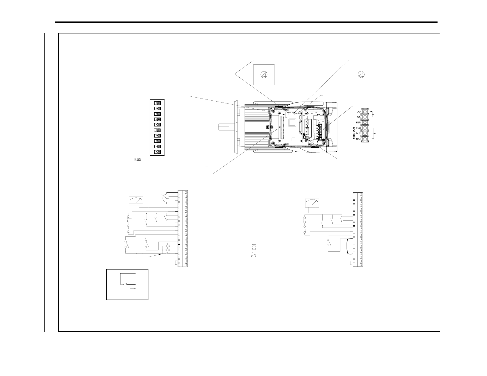
Top View of Unit
With Cover Removed
Display Board
Connector
Accel / Decel Switch
0 = 1 sec accel / 5 sec decel
1 = 5 sec (Default)
6
7
2 = 10 sec
5
0
3 = 15 sec
4
4 = 20 sec
1
5 = 30 sec
3
2
6 = 60 sec
7 = 90 sec
(Stop to Max Spd)
AC Input Power
Connections
DC Bus (Do Not Wire)
- DBR (Do Not Wire)
AC Inputs
Ground
Control Signal Terminal Block Connections
1>
RPM
%LOAD
Momentary 3-Wire
Start
+ -
REV
13
+10VDC
2>
5K
FWD
Connect to external
device such as PLC
input.
Standard Unit
1 10 Volt Reference
2 0 to 10V Spd Ref Input
3 4 to 20 mA Spd Ref Input
4 Common
5 0 to 10V Output
7 24V DC
8 Speed Preset 2
9 Speed Preset 1
10 Speed Preset 0
11 Function Loss
12 RPM / %Load Display
13 24V DC
14 Forward/Reverse
15 Reset
16 Start
3>
17 Stop
18 24 DC Common
19 N.O. Relay
20 Relay Common
= N.O. Momentary Contact
= N.C. Momentary Contact
= Maintained Contact - Closed
= Maintained Contact - Open
1>
Local Operator Control Unit
2>
+ -
RPM
%LOAD
3>
Connect to external
device such as PLC
input.
1 10 Volt Reference
2 0 to 10V Spd Ref Input
3 4 to 20 mA Spd Ref Input
4 Common
5 0 to 10V Output
6 Common6 Common
7 24V DC
8 Speed Preset 2
9 Speed Preset 1
10 Speed Preset 0
11 Function Loss
12 RPM / %Load Display
13 24V DC
14 Forward/Reverse
15 Reset
16 Start
17 Stop
18 24 DC Common
19 N.O. Relay
20 Relay Common
Maintained 2-Wire
Start
16
17
1> The jumper between te rm inals 7 and 11
must be removed when wiring the
Function Loss input. See s ec t ion 7.1 for
more information.
2> An external 0 to 10 volt or 4 t o 20 mA
speed reference sou rc e c an be connected.
See section 7.5.3 for more information.
3>
block inputs, the jumper bet w een terminals 13 and
17 must be removed when wiring the Stop input. See
section 7.6 for more informa t ion.
To stop the unit using the ter m inal
Important:
Page 11

C
HAPTER
1
Step 1 - Identify Your Unit
The VSM500™ integrated drive/motor is an AC drive integrally mounted with an
inverter duty motor. Each unit consists of a drive section and a motor section.
The drive section is a single- or three-phase input, three-phase output inverter
providing open loop V/Hz regulation. It houses the PC boards and the blower. The
motor section is a four-pole, three-phase induction motor.
The unit’s default setup suits a wide range of applications. Two rotary switches and a
10-position slide switch on the Regulator board are used to adjust the setup, if
required.
VSM500 units are identified by model number. This number appears on the shipping
label and on the unit’s nameplate. Table 1.1 shows the format of this number and what
it indicates.
Table 1.1 – Model Number Format
nn n a a n n n n
Horsepower
1 = 1 HP
2 = 2 HP
3 = 3 HP
5 = 5 HP
Frame
0 = 56
1 = 140
2 = 180
Regulator
X = CT / VT
Display
S = Standard
W = Operator Controls
Input Voltage
1 = 1-Phase, 115 VAC
2 = 3-Phase, 230 VAC
3 = 1-Phase, 230 VAC
4 = 3-Phase, 460 VAC
CE Certification
0 = Without Mains Filter
Enclosure Type
0 = Drive Section Only
1 = Standard
Mounting
1 = C-face and Foot
Standard units, described in section 1.1, provide remote operator control. Local
operator control units, described in section 1.2, provide local (default) or remote (user
option) control.
Step 1 - Identify Your Unit
1-1
Page 12
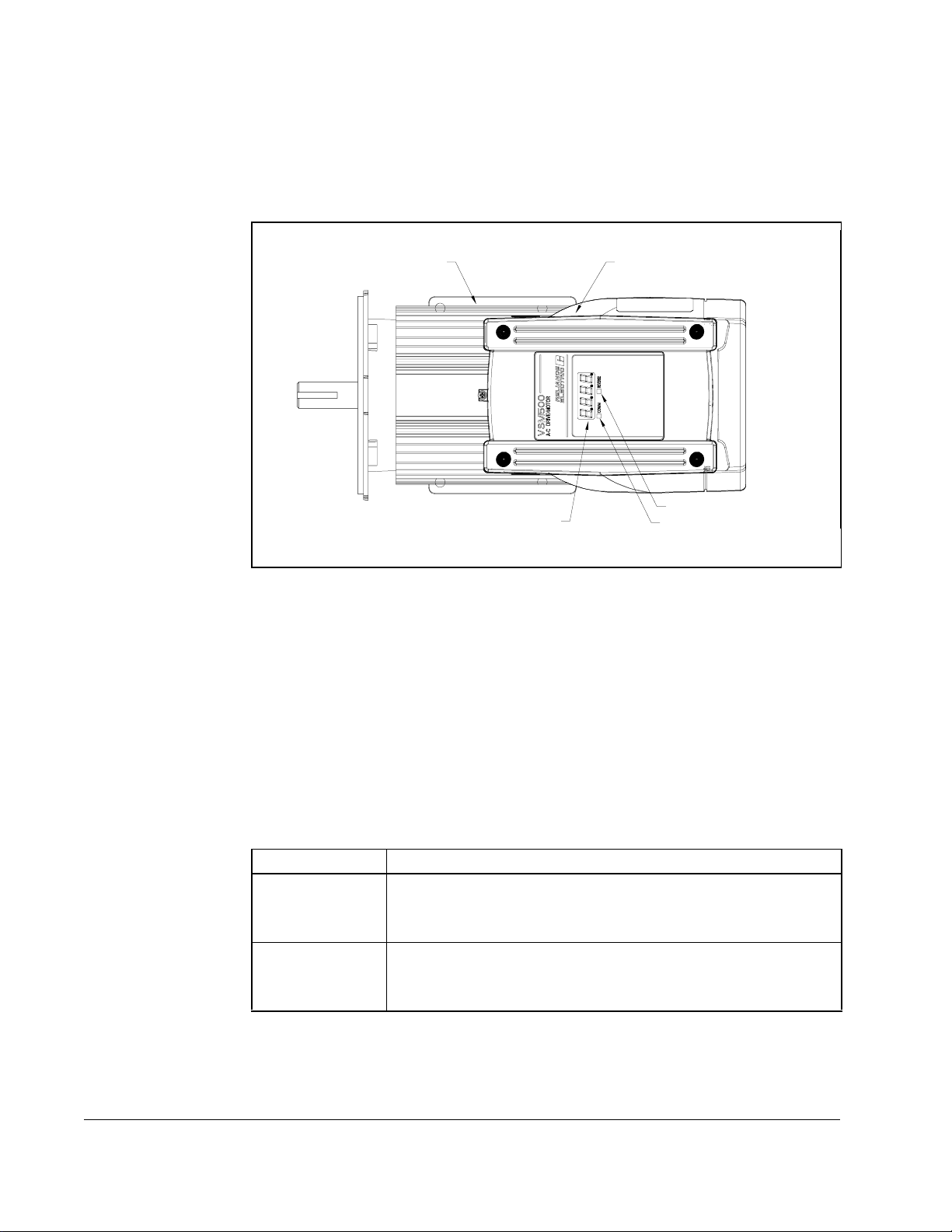
1.1 VSM500 Standard Unit
The standard unit, shown in figure 1.1, provides a local display for speed or %load,
and diagnostic information. A control signal terminal block in the drive section
connects to a user-supplied remote operator control station.
Motor Section
Drive Section
Display
Figure 1.1 – VSM500 Standard Unit
1.1.1 Standard Unit Display Description
The four-character, seven-segment display shows the drive’s output speed in RPM or
%load, and displays active fault codes. Speed in RPM is the default display. To display
%load, see section 7.4.
If a fault occurs, the unit displays the corresponding fault code. Refer to chapter 11 for
more information about fault codes and corrective actions.
1.1.2 Standard Unit Reverse LED Description
The REVERSE LED indicates the requested direction of motor rotation:
LED Status Definition
OFF The requested direction of motor rotation is forward.
(The VSM500 unit is shipped with the forward direction defined
as CCW shaft rotation as viewed from the motor shaft end.)
ON The requested direction of motor rotation is reverse.
(The VSM500 unit is shipped with the reverse direction defined
as CW shaft rotation as viewed from the motor shaft end.)
Reverse LED
Communications LED
1-2
Note that if the motor is turning and you request a change to motor direction, the LED
turns on or off immediately even though it may take some time for the motor to
decelerate and begin turning in the opposite direction.
Installing and Operating the VSM500 Integrated Drive/Motor, Version 3.0
Page 13
1.1.3 Standard Unit Communications LED Description
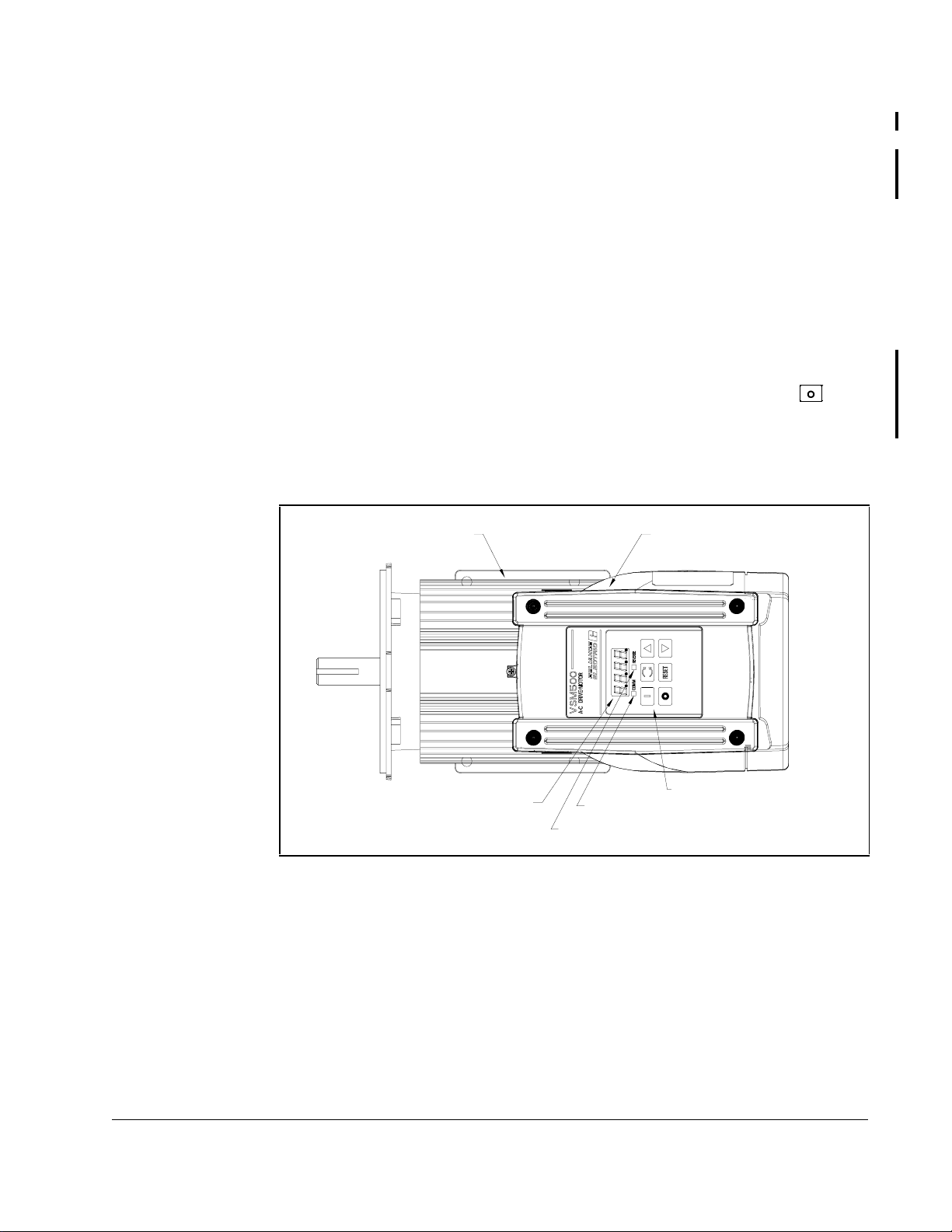
Motor Section
Drive Section
Display
Reverse LED
Local Operator Controls
Communications LED
The communications LED (COMM) is used only with the VSM500 DeviceNet option.
Refer to the VSM500 DeviceNet Option Board instruction manual, D2-3463, for more
information about this LED.
1.2 VSM500 Local Operator Control Unit
The local operator control unit (see figure 1.2) provides local start, stop, forward,
reverse, reset, and speed control functions. The controls replace the Start, Stop,
Reset, and F or war d / Re v erse i nput sig nals a t the te rminal b loc k. F or lo cal con trol, y ou
do not wire to these inputs.
V ersion 3.0 and later units provide the option to control the unit from the terminal block
instead of the local operator controls. In this case, you wire to the Start, Stop, Reset,
and Forward / Reverse input signals at the terminal block. Note that the red
used to stop the unit when the unit is set up for local (local operator controls) or remote
can be
(terminal block) control. See section 8.3.9, Start Mode Select, for a description of this option.
The local operator control unit receives its speed reference from the keypad (default)
or the analog input terminals (user option). Refer to section 8.3.2 for more information.
key
Step 1 - Identify Your Unit
Figure 1.2 – VSM500 Local Operator Control Unit
1-3
Page 14
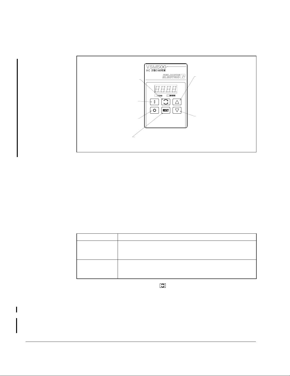
1.2.1 Local Operator Control Unit Key Descriptions
Figure 1.3 shows each key’s function.
Use the FORWARD/REVERSE key
to toggle the direction of motor
rotation.
Use the START key to apply
power to the motor section.
Use the STOP key to turn off
the drive section output to the
motor section.
Figure 1.3 – Local Operator Controls Key Functions
Use the RESET key to reset
any active faults or cancel an
Auto Restart sequence.
Press the UP ARROW key once to
display the current speed reference.
Hold this key down to increase
the speed reference value. The
longer this key is pressed, the
faster the reference value will
change.
Press the DOWN ARROW key once to
display the current speed reference.
Hold this key down to decre a se
the speed reference value. The
longer this key is pressed, the
faster the reference value will
change.
1.2.2 Local Operating Control Unit Display Description
The four-character, seven-segment display shows output speed in RPM or %load, the
current speed reference, and active fault codes. Speed in RPM is the default display.
To display %load, see section 7.4.
If a fault occurs, the unit displays the corresponding fault code. Refer to chapter 11 for
more information about fault codes and corrective actions.
1-4
1.2.3 Local Operating Control Unit Reverse LED Description
The REVERSE LED indicates the requested direction of motor rotation:
LED Status Definition
OFF The requested direction of motor rotation is forward.
(The VSM500 unit is shipped with the forward direction defined as
CCW shaft rotation as viewed from the motor shaft end.)
ON The requested direction of motor rotation is reverse.
(The VSM500 unit is shipped with the reverse direction defined as
CCW shaft rotation as viewed from the motor shaft end.)
Note that if the motor is turning and the key is pressed, the LED turns on or off
immediately even though it may take some time for the motor to decelerate and begin
turning in the opposi te direc ti on.
1.2.4 Local Operator Control Unit Communications LED Description
The communications LED (COMM) is used only with the VSM500 DeviceNet option.
Refer to the VSM500 DeviceNet Option Board instruction manual, D2-3463, for more
information about this LED.
Installing and Operating the VSM500 Integrated Drive/Motor, Version 3.0
Page 15
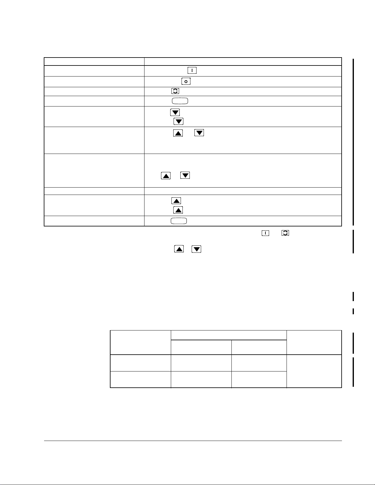
1.2.5 Operating the Unit Using the Local Operator Controls
Desired Action User Steps
Start the unit.
Stop the unit.
Change the direction of motor rotation.
Clear faults.
Decrease the speed reference.
Display the current speed
reference
Display the speed in RPM No action required; speed in RPM is the default display based on status of
Display %load Close contact on terminal 12 (see section 7.4)
Increase the speed reference.
Cancel Auto Restart sequence.
1
2
2
1
If the unit is set up for terminal block control (see section 8.3.9), the and
2
If the unit is using a preset speed reference (see section 7.4.1) or terminal block speed reference (see
section 8.3.2), pressing the or key will have no effect on unit operation.
Press the green key.
Press the red key.
1
Press the key.
Press the key.
Press the key until the speed reference displayed is the desired value. The
longer the key is held down, the faster the value decreases.
Press the or key once.
The display returns to indicating speed in RPM or %load after three to five
seconds. (Note that holding down either key will change the speed reference.)
terminal 12 (see section 7.4).
If the or keys are not pressed for several seconds , the dis pla y returns
to indicating actual motor speed in RPM.
Press the key until the speed reference displayed is the desired value. The
longer the key is held down, the faster the value increases.
Press the key.
RESET
RESET
keys are not functional.
Important:
If the local operator controls are disconnected from or connected to the
unit after power up, the unit will stop due to a non-resettable fault. Refer to
chapter 11 for information about faults.
1.3 Option Kits
Table 1.2 lists the VSM500 option kits.
Drive Input Rating
115V, 230V
Single Phase
230V, 460V
Three Phase
Table 1.2 – VSM500 Option Kits
CE Filter Option Kit DeviceNet
Communication
VSM-CE-1I VSM-CE-1E
VSM-CE-3I VSM-CE-3E
Option KitInternal Mount External Mount
DNVSM500
Step 1 - Identify Your Unit
1-5
Page 16

1-6
Installing and Operating the VSM500 Integrated Drive/Motor, Version 3.0
Page 17
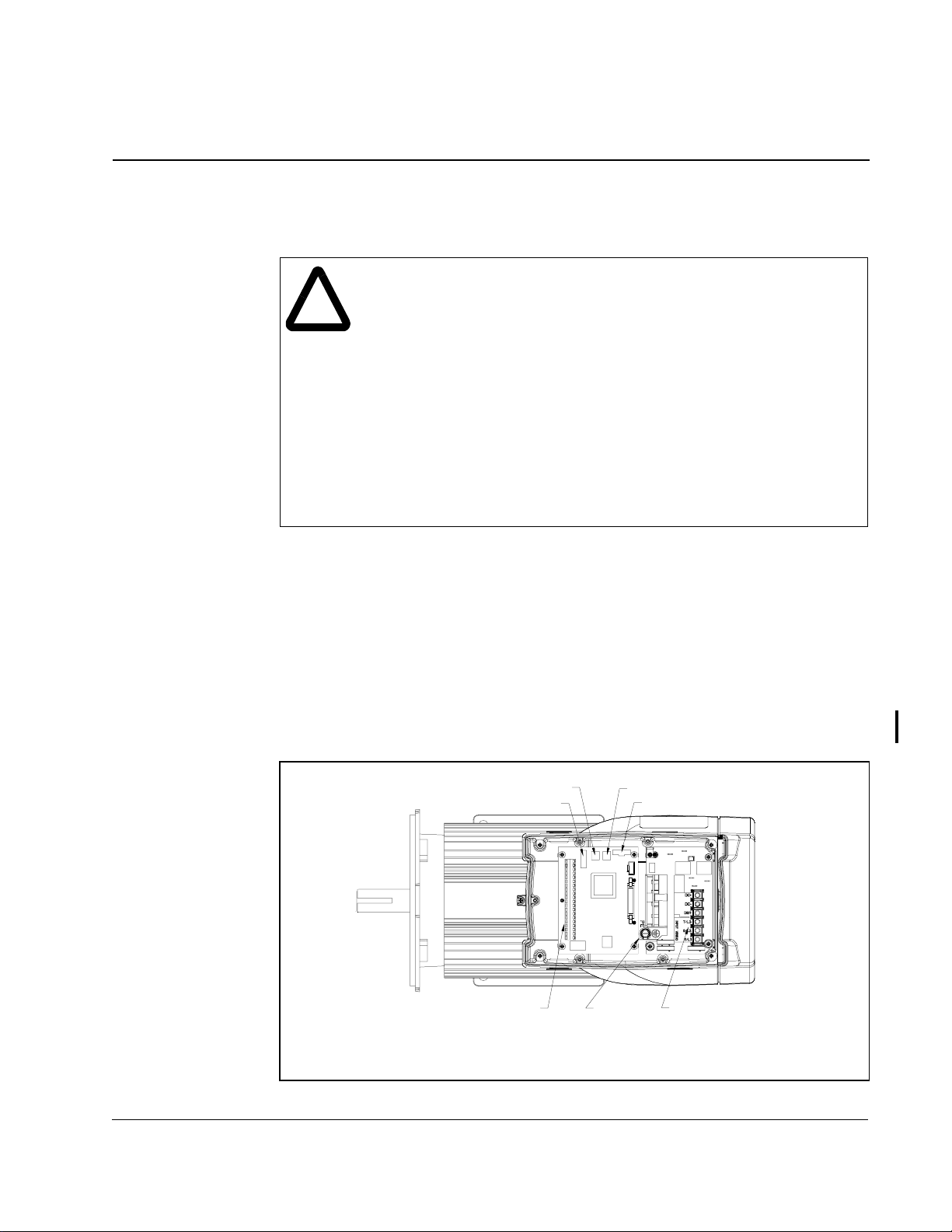
C
Accel/Decel Switch
Display Board Connector
Ground
Control Signal
Terminal Block
Max Speed Switch
Setup Slide Switch
AC Input Power
Terminal Block
Top View of Unit with
Drive Section Cover Removed
HAPTER
2
Step 2 - Plan the Installation
ATTENTION:Only qualified electrical personnel, familiar with the
construction and operation of this equipment and the hazards involved,
!
It is the user’s responsibility to ensure that this equipment is installed properly
according to this manual and in conformance with all applicable codes. Consult your
local inspecting agency for information about any local, national, or international
codes that may apply.
should install, adjust, operate, and/or service this equipment. Read and
understand this instruction manual in its entirety before proceeding.
Failure to observe this precaution could result in severe bodily injury or
loss of life.
ATTENTION:This equipment is at line voltage when AC power is
connected. Disconnect and lockout all ungrounded conductors of the
AC power line before working on the unit. Failure to observe these
precautions could result in severe bodily injury or loss of life.
ATTENTION:The user is responsible for conforming with all applicable
local, national, and international codes. Failure to observe this
precaution could result in personal injury and/or damage to, or
destruction of, the equipment.
Review all installation and wiring instructions thoroughly before proceeding.
Throughout the installation procedures, use figure 2.1 to locate wiring termination
points and setup switches.
If the VSM500 unit installation must be in compliance with the European Community
Electromagnetic Compatibility Standards, refer to appendix F before proceeding.
Figure 2.1 – Component Location
Step 2 - Plan the Installation
2-1
Page 18
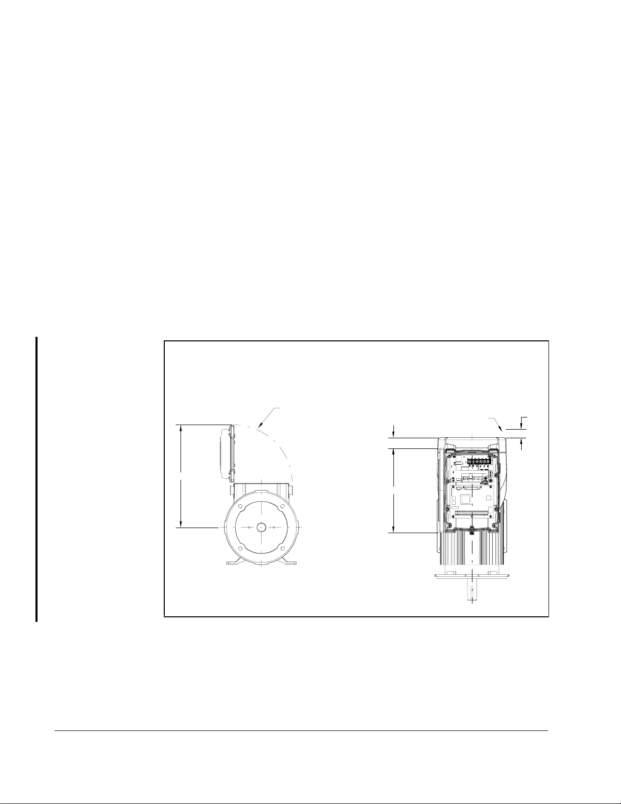
Planning the installation is necessary to ensure you have acceptable environmental
and operating conditions for the unit. Read and follow the requirements given below
before proceeding with the installation:
•
Locate the unit where it will have unrestricted clearance as shown in figure 2.2.
•
Locate the unit where it will be kept clean (away from oil, coolants, or airborne
contaminants). The VSM500 unit has an IP54/Type 12 rating. An IP rating
designates the enclosure’s level of protection. The first number in the rating (5)
indicates that the VSM500 unit is dust-resistant. The second number (4) indicates
that the unit is splashproof.
•
Mount the unit on a flat surface.
•
Verify that the ambient temperature will remain between 0°C to 40°C (32°F to
°
F).
104
•
Verify that the relative humidity will be between 5% and 95%, non-condensing.
•
For installations above 1000 meters (3300 feet), refer to appendix A for derating
guidelines.
•
Verify that there will be adequate clearance for opening the cover. See figure 2.2.
•
Verify that there will be adequate clearance for blower intake. See figure 2.2.
12.50
Front View
Clearance
1.30
10.25
Figure 2.2 – Access Clearances
Top View
Blower IntakeCover
Clearance
1.00
2-2
Installing and Operating the VSM500 Integrated Drive/Motor, Version 3.0
Page 19
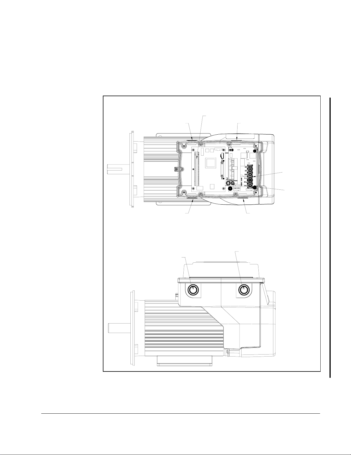
Control Signal
Terminal Block
AC Input Power
Control Signal
AC Input Power
Wiring
Wiring
Top View
Side View
Ground
Control Signal
Wiring
Control Signal
Wiring
AC Input Power
Wiring
AC Input Power
Wiring
Terminal Block
2.1 Wire Routing Guidelines
The VSM500 unit is shipped from the factory with plastic conduit plugs installed.
These plugs must be removed. Before wiring, replace these plugs with appropriate
3/4-inch NPT connectors having a similar enclosure rating. After wiring, seal unused
routing holes using permanent, user-supplied 3/4-inch NPT plugs. Seal all threaded
connections. Route the power and control wiring as shown in figure 2.3.
Step 2 - Plan the Installation
Figure 2.3 – Wire Routing Locations
2-3
Page 20

2.2 Handling and Lifting Guidelines
Follow these handling and lifting guidelines:
•
In the case of assemblies on a common base, carefully lift the assembly by a sling
around the base or by other lifting means on the base.
•
When designing the lifting means, take care to assure lifting in the intended
direction.
•
Do not lift the unit by the plastic blower cover.
•
Do not use any lifting means under the drive section.
•
Do not lift attached equipment by lifting the motor.
•
Do not use the VSM500 unit as a step.
2-4
Installing and Operating the VSM500 Integrated Drive/Motor, Version 3.0
Page 21

C
HAPTER
Step 3 - Mount the Unit
Mount the unit on a foundation sufficiently rigid to prevent excessive vibration. The unit
may be mounted at any orientation. After carefully aligning the VSM500 unit with the
driven machinery, bolt securely in place.
When the unit is mounted vertically, it may be necessary to use additional guards to
prevent foreign objects from falling into the motor openings and striking rotating parts.
Mounting dimensions are provided on the following pages of this chapter.
3.1 Mounting Guidelines for Reliance Face-Mounted
Motors
Use the following guidelines when mounting Reliance 56C and 140C face-mounted
motors:
•
Before mounting a C-face motor to the mating flange, be sure both surfaces and all
mounting holes are smooth and free of debris.
3
•
When mounting into a quill-type reducer, make sure the input and output shafts are
coated with an anti-seize compound suitable for the application.
•
When mounting through a flexible coupling, make sure that there is adequate
clearance between the driven equipment shaft, the coupling interface, and the motor
shaft. Insufficient clearance may result in binding of the shafting and premature
bearing failure.
•
Always slide the motor tenon into the mating flange to its full depth before tightening
the mounting bolts. Do not allow the motor to hang by the shaft extension while
assembling it to the driven equipment (for example, a quill input gear case) as this
may bend or crease the shaft and damage any seals that are present.
•
Make sure to use the proper mounting bolts. For 56C and 140C motors, these
should be 9.5 mm (0.38 in) and sized for length such that engagement into the
motor flange does not exceed 14.3 mm (0.563 in).
For example, a gearcase with a 9.5 mm (0.38 in) flange thickness requires a bolt
that is 9.5 mm (0.38 in) + 14.3 mm (0.56 in). That is, 23.8 mm (0.94 in) should be
the maximum bolt length. Since 23.8 mm (0.94 in) is not a standard bolt length, a
22.2 mm (0.88 in) bolt or a 25.4 mm (1.0 in) bolt with a lock washer can be used.
Important:
Using a bolt that is too long may cause damage to the motor resulting in
premature failure and/or a loose assembly.
Step 3 - Mount the Unit
3-1
Page 22
3/4 Conduit
Both Sides
45°
Face Runout & Eccentricity .004 Max. T.I.R.
Shaft Runout .002 Max. T.I.R.
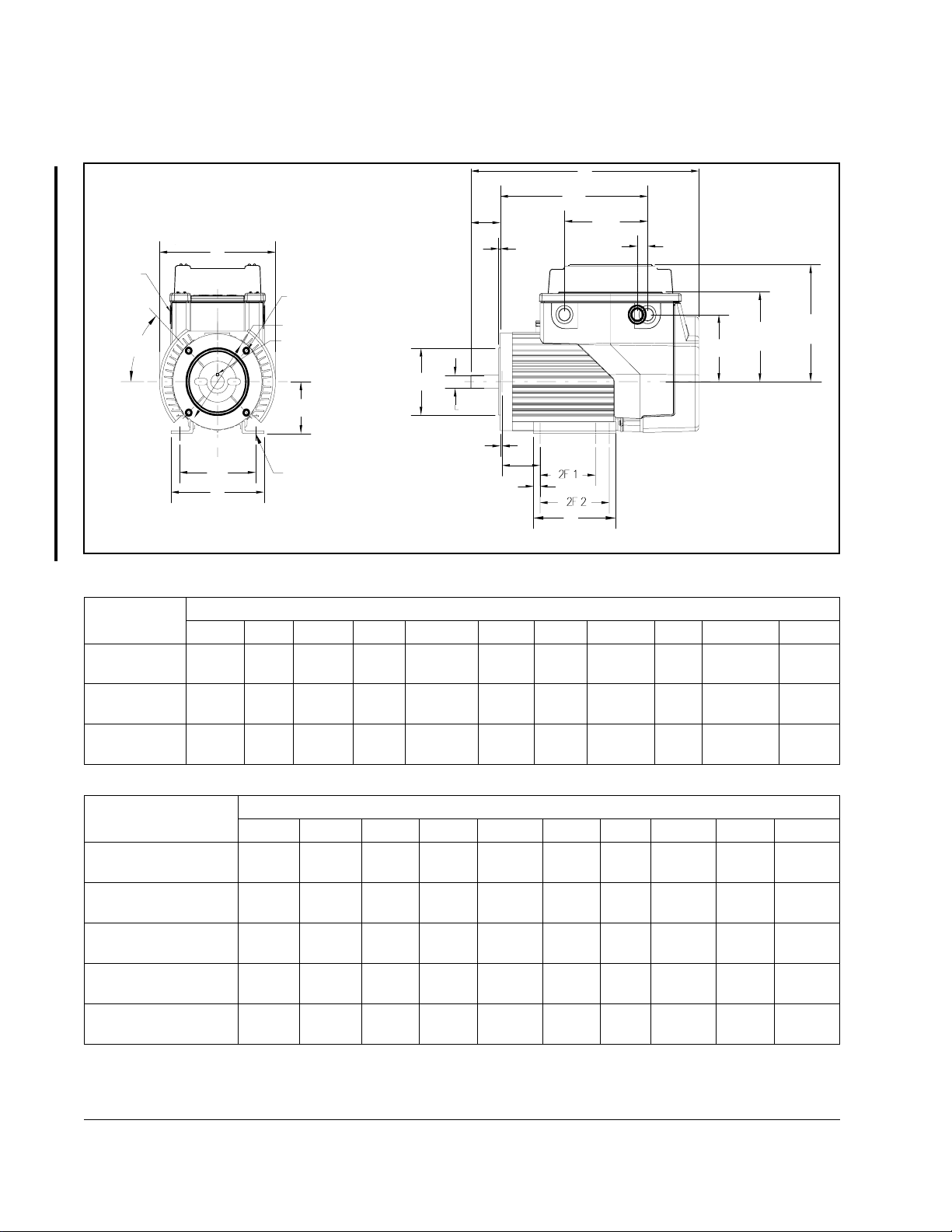
3.2 Mounting Dimensions for NEMA Frames
C
BV
6.00
BB
*
B
.75
**
AH
P
BF
AJ
S - Key Width/Height
ES - Key Length
AK
D
2E
A
H - Diameter Through
* Denotes Control Wiring Ports
** Denotes Input Power Port Opposite Side
Figure 3.1 – NEMA Frame Mounting Dimensions
U
BC
BA
EV
4.50
6.01
Short Cover
7.86
Std. Cover
Dimensions in inches (mm)
Frame Size A 2E H D BF AJ AK U AH S ES
56C 6.71
(170)
143TC
145TC
182TC
184TC
6.71
(170)
8.50
(216)
5.50
(140)
5.50
(140)
7.50
(191)
0.34
(8.6)
0.34
(8.6)
0.34
(8.6)
3.50
(89)
3.50
(89)
4.50
(114)
3/8-16 5.88
(149)
3/8-16 5.88
(149)
1/2-13 7.25
(184)
4.50
(114)
4.50
(114)
8.50
(216)
0.625
(15.9)
0.875
(22.3)
1.125
(28.6)
2.06
(52)
2.12
(54)
2.62
(67)
.19 SQ
(4.8)
.19 SQ
(4.8)
.25 SQ
(6.4)
Dimensions in inches (mm)
Frame Size BC BB BA B 2F 1 2F 2 EV C P BV
56C -0.19
(-4.8)
143TC 0.12
(3.0)
145TC 0.12
(3.0)
182TC 0.12
(3.0)
184TC 0.12
(3.0)
0.12
(3.0)
0.12
(3.0)
0.12
(3.0)
0.25
(6.4)
0.25
(6.4)
2.75
(70)
2.75
(70)
2.75
(70)
3.50
(89)
3.50
(89)
6.50
(165)
6.50
(165)
6.50
(165)
6.50
(165)
6.50
(165)
3.00
(76)
4.00
(102)
4.00
(102)
4.50
(114)
4.50
(114)
5.00
(127)
5.00
(127)
5.00
(127)
5.50
(140)
5.50
(140)
0.47
(12)
0.47
(12)
0.47
(12)
0.50
(13)
0.50
(13)
15.90
(404)
16.46
(418)
15.96
(405)
18.75
(476)
19.75
(502)
8.38
(213)
8.38
(213)
8.38
(213)
8.80
(224)
8.80
(224)
10.14
(258)
10.14
(258)
10.64
(270)
12.39
(315)
13.39
(340)
1.25
(32)
1.25
(32)
1.50
(38)
3-2
Installing and Operating the VSM500 Integrated Drive/Motor, Version 3.0
Page 23
Step 4 - Install External Components
Install external components using the guidelines in the following sections.
4.1 Installing an AC Input Disconnect
C
HAPTER
4
ATTENTION:
provided i n the i ncomi ng po wer lines . Failure to observ e thi s prec aution
!
An AC input disconnect must be provided in the incoming power lines in accordance
with NEC/CEC guidelines.
could result in severe bodily injury or loss of life.
The NEC and CEC require that an input disconnect be
4.2 Installing Branch Circuit Protection
ATTENTION:
be provided to protect input power wiring. The input fuse ratings listed
!
Install the required, user-supplied branch circuit protection fuses according to
NEC/CEC guidelines. Refer to table 4.1 for recommended fuse ratings.
Model Number Input Voltage Unit HP
1_X_4_1_ 460 VAC 1 HP 2.3 A 3.5 A
2_X_4_1_ 460 VAC 2 HP 3.7 A 6.0 A
3_X_4_1_ 460 VAC 3 HP 5.7 A 9.0 A
5_X_4_1_ 460 VAC 5 HP 9.0 A 15.0 A
1_X_2_1_ 230 VAC 1 HP 4.5 A 7.0 A
2_X_2_1_ 230 VAC 2 HP 7.6 A 12.0 A
1_X_3_1_ 230 VAC (1-Phase) 1 HP 5.8 A 9.0 A
2_X_3_1_ 230 VAC (1-Phase) 2 HP 14.0 A 20.0 A
1_X_1_1_ 115 VAC 1 HP 14.0 A 20.0 A
1
Recommended fuse type: UL Class J or CC, 600 V, time delay.
in table 4.1 are applicable for one VSM500 unit per branch circuit. No
other load can be applied to that fused branch circuit. Failure to observe
this precaution could result in severe bodily injury or loss of life.
The NEC/CEC requires that upstream branch protection
Table 4.1 – Required AC Branch Circuit Protection
NEC Amps Input
Input
Current
Rating
Fuse
1
Step 4 - Install External Components
4-1
Page 24

4.3 Installing Input Isolation Transformers
ATTENTION:
recommended system KVA (100 KVA for 460 VAC three-phase, 5%
!
Depending upon the requirements of the application, the VSM500 unit may require
input isolation transformers to help eliminate the following:
•
Damaging AC line voltage transients from reaching the VSM500 unit.
•
Line noise from the VSM500 unit being fed back to the incoming power source.
An isolation transformer or line reactors of 3% drive input impedance should be used
between the distribution source and the VSM500 unit in situations such as the
following:
•
The power distribution system feeding the VSM500 unit contains power factor
correction capacito rs.
•
The power distribution system feeding the VSM500 unit connects with heavy
industrial equipment that causes instantaneous line distribution shorts such as arc
welders, line-commutated thyristor converters, or line-started AC induction motors
greater than 50 HP (37 KVA).
•
The distribution transformer is rated more than 100 KVA for 460 VAC with less than
5% impedance.
impedance) requires using an isolation transformer, a line reactor, or
other means of adding similar impedance. Failure to observe this
precaution could result in damage to, or destruction of, the equipment.
Distribution system capacity above the maximum
•
The distribution system is prone to frequent power outages or transient power
interruptions or significant voltage spikes.
Refer to table 4.2 for the appropriate line reactor for your unit.
Table 4.2 – Input Line Reactors
VSM500 Unit Input Line Reactor
Rated
HP Input Voltage Inductance
1 460V, 3-Phase 6.5 mH 4.0 608895-63D
2 460V, 3-Phase 3.0 mH 8.0 608895-63F
3 460V, 3-Phase 2.5 mH 12.0 608895-63H
5 460V, 3-Phase 1.5 mH 18.0 608895-63K
1 230V, 3-Phase 1.5 mH 8.0 608895-63E
2 230V, 3-Phase 0.8 mH 18.0 608895-63J
A power-disconnecting device must be installed between the power line and the
primary of the transformer. If the power-disconnecting device is a circuit breaker, the
circuit breaker trip rating must be coordinated with the in-rush current (10 to 12 times
full load current) of the transformer.
Amps Reliance Part No.
4-2
Installing and Operating the VSM500 Integrated Drive/Motor, Version 3.0
Page 25

C
HAPTER
Step 5 - Wire AC Power to the Unit and
Ground the Unit
ATTENTION:If the distribution system capacity exceeds the unit’s
maximum symmetrical fault short-circuit current of 10,000 amps,
!
Observe the following guidelines when wiring AC power:
additional impedance should be added to the AC line supplying the unit
to limit available current in the event of a fault. Failure to observe this
precaution could result in severe bodily injury or loss of life.
ATTENTION:The unit is intended to be commanded by control input
signals that will start and stop the motor. A device that routinely
disconnects then reapplies input power to the unit for the purpose of
starting and stopping the motor should not be used. If it is necessary to
use this method for starting and stopping, or if frequent cycling of power
is unavoidable, make sure that it does not occur more than once a minute.
Failure to observe this precaution could result in damage to equipment.
5
•
The terminal block accepts up to 3.31 mm2 (12 AWG) wire.
•
The recommended tightening torque is 1.3 Nm (12 in-lb).
•
Verify that the input power to the unit corresponds to the unit voltage and frequency
and that the input supply is of sufficient capacity to support the input current
requirements. Refer to appendix A, Technical Specifications.
•
Size the AC line conductors for the unit rating and in accordance with all applicable
local, national, and international codes.
Step 5 - Wire AC Power to the Unit and Ground the Unit
5-1
Page 26
Use the following procedure to wire AC power to the unit. Grounding instructions are
provided in section 5.1.
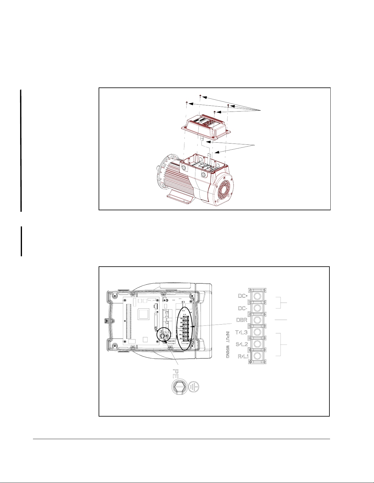
Step 1. Remove the cover by loosening the four cover screws. Note that the display
ribbon cable is designed to disconnect from the main unit when the cover is
removed as shown in figure 5.1.
Cover Screws (4)
Display Board
Ribbon Cable Connector
Figure 5.1 – Removing the Cover
Step 2. For three-phase input: Connect the incoming three-phase AC line to
terminals R, S, and T, as shown in figure 5.2.
For single-phase input: Connect the incoming single-phase AC line to any
two of the terminals R, S, T shown in figure 5.2.
Drive Section with Cover Off
DC Bus
[Not Used]
AC Inputs
AC Input Terminal Block
Ground
5-2
Figure 5.2 – AC Input Power Connections
Installing and Operating the VSM500 Integrated Drive/Motor, Version 3.0
Page 27

5.1 Grounding the Unit
ATTENTION:
national, and international codes applicable to the grounding of this
!
Connect the ground wire brought in with the incoming AC power to the unit’s
grounding screw (see figure 5.2). This grounding conductor must run unbroken from
the unit to earth ground. The recommended tightening torque is 2.6 Nm (32 in-lb).
equipment. Failure to observe this precaution could result in severe
bodily injury or loss of life.
The user is responsible for conforming with all local,
Step 5 - Wire AC Power to the Unit and Ground the Unit
5-3
Page 28

5-4
Installing and Operating the VSM500 Integrated Drive/Motor, Version 3.0
Page 29

C
HAPTER
6
Step 6 - Install an Emergency Stop
ATTENTION:
stop circuit outside of the VSM500 unit circuitry. This circuit must disable
!
Depending upon the requirements of the application, the VSM500 unit can be set up
to provide either a coast-to-rest (default) or a ramp-to-rest (user option) operational
stop. The unit’s Function Loss input provides an additional coast-to-rest operational
stop.
In addition to the operational stop, the user must provide a hardwired emergency stop
external to the unit. The emergency stop circuit must contain only hardwired
electromechanical components. Operation of the emergency stop must not depend on
electronic logic (hardware or software) or on the communication of commands over an
electronic network or link.
the system in case of improper operation. Uncontrolled machine
operation may result if this procedure is not followed. Failure to observe
this precaution could result in bodily injury.
The user must provide an external, hardwired emergency
6.1 Complia nce with Machinery Safety Standard
EN 60204-1: 1992
This section applies to users who must comply with EN 60204-1: 1992, Electrical
equipment of industrial machines, part 9.2.5.4, Emergency Stop.
The VSM500 coast-to-rest stop is a category 0 operational stop. The ramp-to-rest
stop is a category 1 operational stop.
The required external hardwired emergency stop must be either a category 0 or 1
stop, depending on the user’s risk assessment of the associated machinery. In order
to fully comply with EN 60204-1: 1992, part 9.2.5.4, at least one of the system’s stop
methods must be a category 0 stop.
Step 6 - Install an Emergency Stop
6-1
Page 30

6-2
Installing and Operating the VSM500 Integrated Drive/Motor, Version 3.0
Page 31

C
HAPTER
7
Step 7 - Wire the Control Signal
Terminal Block
The following sections describe how to wire the control signal terminal block shown in
figure 7. 1.
Refer to either figure 7.2 (standard units or local operator control units set up for
terminal block control) or figure 7.3 (local operator control units) before you begin
wiring. These figures show typical wiring connections and the sections in this chapter
where the signals are described in detail.
Note the following when wiring the terminal block:
•
The terminal block is isolated from the input power.
•
Route the control wires separately from the power wires.
•
The terminal block accepts 0.326 mm2 (22 AWG) through 3.31 mm2 (12 AWG) wire.
•
The maximum lead length is 300 meters (1000 ft).
•
The maximum tightening torque is 0.8 Nm (7 in-lb).
0 to 10V Speed Reference Input
4 to 20mA Speed Reference Input
1> The jumper between terminals 7
and 11 must be removed when
wiring the Function Loss input. See
section 7.1 for more information.
10 Volt Reference
Common
0 to 10V Output
Common
24V DC
Speed Preset 2
Speed Preset 1
Speed Preset 0
Function Loss
RPM / %Load Display
24V DC
Forward/Reverse
Reset
Start
Stop
24V DC Common
N.O. Relay
Relay Common
Control Signal Terminal Block
2> Important: To stop the unit using the
1
2
3
4
5
6
7
8
9
10
11
12
13
14
15
16
17
18
19
20
terminal block inputs, the jumper
between terminal s 13 and 17 must be
removed when wiring the Stop input .
See section 7.6 for more information.
1>
2>
Step 7 - Wire the Control Signal Terminal Block
Figure 7.1 – Control Signal Terminal Block
7-1
Page 32

Drive Section with Cover Removed
Maintained 2-Wire
Start
+10VDC
REV
2>
5K
FWD
3>
+
-
1>
13
RPM
16
17
%LOAD
1 10 Volt Reference
2 0 to 10V Speed Reference Input
3 4 to 20 mA Speed Reference Input
4 Common
5 0 to 10V Output
6 Common
7 24V DC
8 Speed Preset 2
9 Speed Preset 1
10 Speed Preset 0
11 Function Loss
12 RPM / %Load Display
13 24V DC
14 Forward/Reverse
15 Reset
16 Start
17 Stop
18 24V DC Common
19 N.O. Relay
20 Relay Common
Control Signal Terminal Block Connections
Standard Unit
N.O. Momentary Contact
=
N.C. Momentary Contact
=
Maintained Contact - Closed
=
Maintained Contact - Open
=
1> The jumper between terminals 7 and 11
must be removed when wiring the Function
Loss input. See section 7.1 for more
information.
2> An external 0 to 10 vo lt or 40 to 20 mA spee d
reference source can be connected. See
section 7.5.3 for more information.
3>
: To stop the unit using the
Important
terminal block inputs, the jumper between
terminals 13 and 17 must be removed when
wiring the Stop input. See section 7.6 for
more information.
User Wiring for Standard Units
Signal
Function Loss 7.1
Analog Output 7.2
Relay Control Output 7.3
RPM / %Load Display 7.4
Speed Reference (
select one
)
Preset Speeds 7.5.1
Speed Potentiometer 7.5.2
External Speed Reference
(0 to 10 VDC or 4 to 20 mA)
Start 7.6
Stop 7.6
Forward / Reverse 7.7
Reset 7.8
Refer to
Section
7.5.3
7-2
Figure 7.2 – T ypical Control Signal Connections for Standard Units and Local Operator Control Units Set Up
for Terminal Block Control
Installing and Operating the VSM500 Integrated Drive/Motor, Version 3.0
Page 33

Drive Section with Cover Removed
2>
_
+
1>
RPM
%LOAD
3>
1 10 Volt Reference
2 0 to 10V Speed Reference Input
3 4 to 20 mA Speed Reference Input
4 Common
5 0 to 10V Output
6 Common
7 24V DC
8 Speed Preset 2
9 Speed Preset 1
10 Speed Preset 0
11 Function Loss
12 RPM / %Load Display
13 24V DC
14 Forward/Reverse
15 Reset
16 Start
17 Stop
18 24V DC Common
19 N.O. Relay
20 Relay Common
Control Signal Terminal Block Connections
Local Operator Control Unit
N.O. Momentary Contact
=
N.C. Momentary Contact
=
Maintained Contact - Closed
=
Maintained Contact - Open
=
1> The jumper between terminals 7 and 11
must be removed when wiring the Function
Loss input. See section 7.1 for more
information.
2> An external 0 to 10 volt or 40 to 20 mA
speed reference source can be connected.
See section 7.5.3 for more information.
3>
To stop the unit using the
Important:
terminal block inputs, the jumper between
terminals 13 and 17 must be removed when
wiring the Stop input. See section 7.6 for
more information.
User Wiring for Local Operator Control Units
Signal Refer to
Function Loss 7.1
Analog Output 7.2
Relay Control Output 7.3
RPM / %Load Display 7.4
Speed Reference (
select one
)
(default = local operator controls)
Preset Speeds 7.5.1
Speed Potentiometer 7.5.2
External Speed Reference
(0 to 10 VDC or 4 to 20 mA)
Section
7.5.3
Figure 7.3 – Typical Control Signal Connections for Local Operator Control Units
Step 7 - Wire the Control Signal Terminal Block
7-3
Page 34

7.1 Wiring Function Loss
For the unit to run, you must maintain a signal at the Function Loss input (the
connection between control terminals 7 and 11). If the Function Loss signal is not
present, the unit turns off the power devices and coasts to rest. To restart the unit, you
must restore the Function Loss signal, clear any faults, and reassert the Start
command.
The unit ships from the factory with a jumper between terminals 7 and 11 which
provides the Function Loss signal. The Function Loss input should be wired in series
with the drive’s external interlocks as shown in figure 7.4. In this case, remove the
jumper before making the connections.
Important:
Function Loss provides an operational stop. It does not fulfill the
requirements of an emergency stop. Refer to chapter 6 for information
regarding emergency stop requirements.
1
2
3
4
5
10
11
12
6
7
24V DC
8
9
Function Loss
User-Supplied
Function Loss
Pushbutton
User-Supplied
Safety Interlocks
13
14
15
16
17
18
19
20
7-4
= N.C. Momentary Contact
=
Maintained Contact - Closed
Figure 7.4 – Function Loss Control Wiring
Installing and Operating the VSM500 Integrated Drive/Motor, Version 3.0
Page 35

7.2 Wiring the Analog Outp ut
The analog output provides a 0 to 10 VDC signal to a user-supplied metering device.
This output indicates speed (default) or %load (user option), based on the status of
input terminal 12.
If you select speed indication, 0 to 10 V = 0 to the maximum speed as defined by the
maximum speed rotary switch. (Refer to chapter 8 for a description of the rotary
switch.)
If you select %load indication, 0 to 10 V = 0 to 200% load.
Wire to the analog output as shown in figure 7.5.
1
2
3
_
+
4
5
6
7
8
9
10
11
12
13
14
15
16
17
18
19
20
0 to 10V Output
Common
Step 7 - Wire the Control Signal Terminal Block
Figure 7.5 – Analog Output Wiring
7-5
Page 36

7.3 Wiring the Relay Control Output
A single form A relay on the terminal block can be used to indicate the unit is running
(default) or has faulted (user option) based on the setup slide switch setting. Refer to
the setup slide switch description in chapter 8.
Wire to the relay control output as shown in figure 7.6.
1
2
3
4
5
6
7
8
9
10
11
12
13
14
15
16
17
Connect to External
Device Such as PLC
Input
18
19
20
N.O. Relay
Relay Common
7-6
Figure 7.6 – Relay Control Output Wiring
Installing and Operating the VSM500 Integrated Drive/Motor, Version 3.0
Page 37

7.4 Wiring RPM or %Load Display
The RPM or %Load Display input (control terminal 12) selects the type of information
displayed by the analog output and the built-in display , speed in RPM or %load. Wire a
switch between control terminals 12 and 13 as shown in figure 7.7.
1
2
3
4
5
6
7
8
9
10
%Load
RPM
11
12
13
14
15
16
17
18
19
20
RPM or %Load Display
24V DC
Figure 7.7 – RPM or %Load Display Wiring
7.5 Wiring the Speed Reference
standard VSM500 unit
The
•
Seven preset speeds
•
An external 0 to 10 VDC or 4 to 20 mA speed reference source
VSM500 unit with local operator controls
The
reference options:
•
The local operator controls (using the keys)
•
Seven preset speeds (the keys are not used)
•
An external 0 to 10 VDC or 4 to 20 mA speed reference source (the keys
are not used)
Select the option that is the most suitable for your application. The following sections
provide wiring information for each option except the local operator controls. Refer to
section 1.2 for information on the local operator controls.
provides two motor speed reference options:
provides three motor speed
Step 7 - Wire the Control Signal Terminal Block
7-7
Page 38

7.5.1 Wiring the Preset Speed Inputs
Control terminals 8, 9, and 10 select seven preset speeds as shown in table 7.1. Note
that if you select a preset speed that is greater than the maximum speed setting
(based on the rotary switch setting), the unit uses the maximum speed setting value.
Important:
Slide switch position 8 defines whether terminals 8, 9, and 10 are used as
presets (default) or to define the unit’s minimum speed (user option).
Refer to section 8.3.8 for information about using terminals 8, 9, and 10 to
select minimum speed.
Table 7.1 – Fixed Preset Speed Selections
Selected Speed Reference
Terminal 8
Status
Terminal 9
Status
Terminal 10
Status Standard Unit
Local Operator
Control Unit
Open Open Open Analog speed reference Local operator control
Open Open Closed Preset 1 - 300 RPM (10 Hz)
Open Closed Open Preset 2 - 600 RPM (20 Hz)
Open Closed Closed Preset 3 - 900 RPM (30 Hz)
Closed Open Open Preset 4 - 1200 RPM (40 Hz)
Closed Open Closed Preset 5 - 1500 RPM (50 Hz)
Closed Closed Open Preset 6 - 1800 RPM (60 Hz)
Closed Closed Closed Preset 7 - 2100 RPM (70 Hz)
To use the preset speeds to set the speed reference, wire to terminals 8, 9, and 10 as
shown in figure 7.8.
7-8
= Maintained Contact - Open
Figure 7.8 – Preset Speed Input Wiring
Installing and Operating the VSM500 Integrated Drive/Motor, Version 3.0
10
11
12
13
14
15
16
17
18
19
20
1
2
3
4
5
6
7
8
9
24V DC
Speed Preset 2
Speed Preset 1
Speed Preset 0
Page 39

7.5.2 Wiring the Speed Reference Signal Potentiometer
Control terminal 1 provides a 10 VDC reference for use with the user-supplied 5 kΩ
potentiometer. Perf orm the following procedure to wire the potentiometer as the speed
reference (refer to figure 7.9):
Step 1. Mount the speed reference potentiometer at an appropriate
operator-accessible location, less than 300 meters (1000 feet) from the
VSM500 unit.
Step 2. Connect one end of the potentiometer to control terminal 1 (10V reference)
and the other end to control terminal 4 (signal common).
Step 3. Connect the potentiometer’s wiper to control terminal 2 (speed reference
input).
+10VDC
5K
1
2
10V Reference
0 to 10V Speed Reference Input
3
4
Common
5
6
7
8
9
10
11
12
13
14
15
16
17
18
19
20
Figure 7.9 – Speed Reference Potentiometer Wiring
Step 7 - Wire the Control Signal Terminal Block
7-9
Page 40

7.5.3 Wiring an External Sp eed Reference (0 to 10 VDC or 4 t o 20 mA)
The terminal block provides both 0 to 10 VDC and 4 to 20 mA inputs. Use only one of
these inputs for the external speed reference. The other input must remain
unconnected.
0 to 10 VDC External Speed Reference
To use an external 0 to 10 VDC signal to set the speed reference, connect the signal
leads as shown in figure 7.10. 0 to 10 VDC = minimum speed to maximum speed.
1
+
_
2
3
4
0 to 10 V Speed Reference Input
Common
5
6
7
8
9
10
11
12
13
14
15
16
17
18
19
20
0 to 10 VDC
Figure 7.10 – 0 to 10 VDC External Speed Reference Wiring
7-10
Installing and Operating the VSM500 Integrated Drive/Motor, Version 3.0
Page 41

4 to 20 mA External Speed Reference
To use an external 4 to 20 mA signal to set the speed reference, connect the signal
leads as shown in figure 7.11. 4 to 20 mA = minimum speed to maximum speed.
1
2
+
_
3
4
4 to 20 mA Speed Reference Input
Common
5
6
7
8
9
10
11
12
13
14
15
16
17
18
19
20
4 to 20 mA
Figure 7.11 – 4 to 20 mA External Speed Reference Wiring
Step 7 - Wire the Control Signal Terminal Block
7-11
Page 42

7.6 Wiring Start / Stop Control
Important:
The system looks for an open-to-closed transition at the Start input before starting the
unit unless you have the Power-Up Start switch (setup slide switch 1, see section
8.3.1) set to ON. If you use a maintained start device and power to the unit is lost, you
must open and reclose the start device before the unit will start again. Both the Stop
and the Function Loss input signals must be present and there must be no active
faults for the unit to start.
In order for the unit to run, you must maintain a signal at the Stop input. If the signal is
interrupted, the unit coasts to rest (default) or ramps to rest (user option). To restart
the unit, you must restore the signal and reassert the Start input.
The unit ships from the factory with a jumper on the Stop input terminals (terminals 13
and 17) which permits the unit to be started. To stop the unit using the terminal block
inputs, you must remove the factory jumper and install appropriate stop wiring.
Figure 7.12 illustrates wiring for a maintained 2-wire and for a momentary 3-wire
Start / Stop control.
1
2
3
4
5
6
7
8
9
10
11
12
13
14
15
16
17
18
19
This applies only to standard units and local operator control units set up
for terminal block control (setup slide switch position 9 = ON, see section
8.3.9).
1
2
3
4
5
6
7
8
9
10
11
12
24V DC
13
24V DC
14
15
Start
Stop
N.O
N.C.
16
17
Start
Stop
18
19
20 20
7-12
Maintained 2-Wire Momentary 3-Wire
= Maintained Contact - Open
= N.O. Momentary Contact
= N.C. Momentary Contact
Important:
terminal block inputs, the jumper between
terminals 13 and 17 must be removed when
wiring the Stop input.
Figure 7.12 – Start / Stop Control Wiring
Installing and Operating the VSM500 Integrated Drive/Motor, Version 3.0
To stop the unit using the
Page 43

7.7 Wiring Forward / Reverse Control
Important:
The Forward / Reverse input (the connection between terminals 13 and 14) defines
the requested direction of motor rotation. If the input is open, the requested direction is
forward. Switching the Forward / Reverse input causes the motor to ramp to rest and
then accelerate in the opposite direction. Note that the VSM500 unit is shipped with
the forward direction defined as CCW shaft rotation as viewed from the motor shaft
end.
Figure 7.13 shows the Forward / Reverse control wiring for the VSM500 unit. If you
disable (lock out) reverse using the setup slide switch, do not wire to this input
because the drive ignores any transition on this input. Refer to the setup slide switch
description in chapter 8.
This applies only to standard units and local operator control units set up
for terminal block control (setup slide switch position 9 = ON, see section
8.3.9).
1
2
3
4
5
6
7
8
9
10
11
12
24V DC
Forward/Reverse
REV
13
14
15
FWD
16
17
18
19
20
Step 7 - Wire the Control Signal Terminal Block
Figure 7.13 – Forward / Reverse Control Wiring
7-13
Page 44

7.8 Wiring Reset Control
Important:
An open-to-closed transition at the Reset input (control terminal 15) clears a fault once
the appropriate corrective action has been taken. After clearing the fault, you must
reassert the Start command in order to restart the unit.
Wire a normally-open (N.O.) pushbutton between control terminals 15 and 13 as
shown in figure 7.14. Refer to chapter 11, Diagnostics and Troubleshooting, for more
information on faults.
This applies only to standard units and local operator control units set up
for terminal block control (setup slide switch position 9 = ON, see section
8.3.9).
1
2
3
4
5
6
7
8
9
10
11
12
13
24V DC
14
15
Reset
16
17
18
19
20
7-14
= N.O. Momentary Contact
Figure 7.14 – Reset Control Wiring
Installing and Operating the VSM500 Integrated Drive/Motor, Version 3.0
Page 45

C
HAPTER
8
Step 8 - Verify the Setup and
Adjust Switches if Required
The VSM500 unit is set up using two rotary switches and a 10-position slide switch
mounted on the printed circuit board as shown in figure 8.1. Figure 8.1 shows the
setting selections and the factory defaults. Normally , no adjustments will be needed
to the facto ry settin gs .
If your application requires adjustment to these settings, refer to the following sections
in this chapter. If no adjustment is needed, go to chapter 9 to complete the installation
procedure.
ATTENTION:Only qualified personnel familiar with the construction and
operation of this equipment and the hazards involved should install,
!
adjust, operate, and/or service this equipment. Read and understand
this instruction manual in its entirety before proceeding. Failure to
observe this precaution could result in severe bodily injury or loss of life.
A T TENT IO N:All adjustments to these components should be made with
power removed. Failure to observe this precaution could result in severe
bodily injury or loss of life.
ATTENTION:After disconnecting input power wait five minutes and
check with a voltmeter to insure that DC bus capacitors are discharged.
The voltmeter should read zero volts. Failure to observe this precaution
could result in severe bodily injury or loss of life.
ATTENTION:The cover screws must be securely tightened in order to
properly ground the cover . Verify that all four cover screws are tight before
applying power to the unit. Failure to observe this precaution could result
in severe bodily injury or loss of life.
Review all setup instructions thoroughly before making any adjustments or applying
power to the unit.
After changing the setup, go to chapter 9 to complete the installation.
Before making any adjustments to the unit, be sure to take the following
precautions:
Step 1. Turn off, lockout, and tag AC input power to the unit.
Step 2. Wait five minutes. Then remove the cover and use a voltmeter to verify that
the DC bus capacitors are discharged. The voltmeter should read zero volts.
Refer to figure 5.2 for the DC bus test points.
Step 8 - Verify the Setup and Adjust Switches if Required
8-1
Page 46

0 = 1500 RPM (50 Hz)
6
5
4
3
1 = 1800 RPM (60 Hz) (D efault)
7
2 = 2100 RPM (70 Hz)
3 = 2400 RPM (80 Hz)
0
4 = 2700 RPM (90 Hz)
1
5 = 3000 RPM (100 Hz)
2
6 = 3300 RPM (110 Hz)
7 = 3600 RPM (120 Hz)
Max Speed Switch
(SW2)
(See section 8.1)
Setup Slide Switch
Power-Up Start Disabled
1> Speed Reference From Operator Controls
Relay Control Output: Running
Auto Restart Disabled
Variable Torque Curve
Coast-to-Rest Stop
Reverse Enabled
0 Hz Minimum Speed
1> Start from Operator Controls
2> Parameter Settings from Setup Switches
(SW3)
(See section 8.3)
1
O
N
4532
867
910
0 = 1 sec accel / 5 sec decel
7
0
1
2
1 = 5 sec (Default)
2 = 10 sec
3 = 15 sec
4 = 20 sec
5 = 30 sec
6 = 60 sec
7 = 90 sec
6
5
4
3
Accel/Decel Switch
(SW1)
(See section 8.2)
Power-Up Start Enabled
Analog Speed Reference From Terminal Block
Relay Control Output: Faulted
Auto Restart Enabled
Constant Torque Curve
Ramp-to-Rest Stop
Reverse Disabled (Reverse Lockout)
Minimum Speed From Terminal Block Inputs
Start from Terminal Block
Parameter Settings from EEPROM Memory
8-2
= Default Setting (Off Position)
1> Switches 2 and 9 apply to local operator control units only.
2> Switch 10 is used with the DeviceNet Communication option only.
Figure 8.1 – Factory Settings for the Setup Rotary Switches and Slide Switch
Installing and Operating the VSM500 Integrated Drive/Motor, Version 3.0
Page 47

8.1 Adjusting t he Maximum Speed
ATTENTION:
and all drive-train mechanisms are capable of safe operation at maximum
!
The maximum speed rotary switch limits the speed reference to the unit. Regardless
of what speed reference is supplied, the unit will not command a speed greater than
the value selected by this rotary switch.
Range:
Default:
To set the maximum speed:
Step 1. To
speed. Failure to observe this precaution could result in severe bodily
injury or loss of life.
1500 RPM (50 Hz) to 3600 RPM (120 Hz)
1800 RPM (60 Hz)
increase
higher position number.
The user is responsible for ensuring that driven machinery
0 = 1500 RPM (50 Hz)
6
7
5
4
3
2
Figure 8.2 – Maximum Speed Rotary Switch
the maximum speed, turn the maximum speed rotary switch to a
1 = 1800 RPM (60 Hz) (Default)
2 = 2100 RPM (70 Hz)
3 = 2400 RPM (80 Hz)
0
4 = 2700 RPM (90 Hz)
1
5 = 3000 RPM (100 Hz)
6 = 3300 RPM (110 Hz)
7 = 3600 RPM (120 Hz)
-or-
decrease
To
lower position number.
Step 2. Connect the display board ribbon cable and replace the cover. Verify that all
four cover screws are in place and tightened.
Step 3. Apply AC input power.
Step 4. Set the operator’s speed reference signal to maximum.
Standard units:
external speed reference device.
Local operator control units:
reference and the key to decrease the speed reference.
Step 5. Use a handheld tachometer to monitor motor speed.
Step 6. Repeat the adjustment procedure until the desired maximum speed is
obtained. Note that changes to the maximum speed setting are recognized
only while the drive is stopped.
Important:
If speed is errati c or not a s ex pected, v erify t hat only one of the speed ref ere nce
inputs (0 to 10 VDC or 4 to 20 mA) has been wired.
the maximum speed, turn the maximum speed rotary switch to a
Use the speed potentiometer or other user-supplied
Use the key to increase the speed
Step 8 - Verify the Setup and Adjust Switches if Required
8-3
Page 48

8.2 Adjusting the Acceleration / Deceleration Time
.
The acceleration / deceleration time is the amount of time it takes the motor to ramp
from stop to the maximum speed setting of the unit. This is also the amount of time it
takes the motor to ramp from the maximum speed setting to stop.
0 = 1 sec accel / 5 sec decel
1 = 5 sec (Default)
2 = 10 sec
7
3 = 15 sec
0
4 = 20 sec
1
5 = 30 sec
6 = 60 sec
7 = 90 sec
Figure 8.3 – Acceleration / Deceleration Rotary Switch
Range:
Default:
6
5
4
3
2
1, 5, 10, 15, 20, 30, 60, 90 seconds
5 seconds
Note that if the operator speed reference setting is less than the maximum speed
value, the acceleration / deceleration ramp time is proportionately less than the
acceleration / deceleration setting.
Assume:
Max Speed = 1800 RPM
Operating Speed = 900 RPM
Accel/Dece l Time Setting = 30 Seconds
Use the following formula:
Operating Speed x Accel/Decel Time Setting = Time to Operating Speed
Max Speed
900 x 30 = 15
1800
Accel Time = the time required to
accelerate from stop to MAX SPEED.
Decel Time = the time required to
decelerate from MAX SPEED to stop.
Example
1800 RPM
900 RPM
SPEED
It will take 15 seconds to ramp from stop to 900 RPM
To adjust the acceleration / deceleration time:
Step 1. To
increase
the acceleration / deceleration time, turn the accel / decel rotary switch
to a higher position number.
-or-
decrease
To
the acceleration / deceleration time, turn the accel / decel rotary
switch to a lower position number.
Step 2. Connect the display board ribbon cable and replace the cover. Verify that all
four cover screws are in place and tightened.
8-4
TIME
15 Sec 30 Sec
Installing and Operating the VSM500 Integrated Drive/Motor, Version 3.0
Page 49

Step 3. Apply AC input power.
Minimum Speed From Terminal Block Inputs
Reverse Disabled (Reverse Lockout)
Ramp-to-Rest Stop
0 Hz Minimum Speed
Reverse Enabled
Coast-to-Rest Stop
867
Analog Speed Reference From Terminal Block
Constant Torque Curve
Auto Restart Enabled
Power-Up Start Enabled
Relay Control Output: Faulted
1> Speed Reference From Operator Controls
Relay Control Output: Running
Power-Up Start Disabled
Variable Torque Curve
Auto Restart Disabled
4532
N
1
O
910
Start from Terminal Block
Parameter Settings from EEPROM Memory
= Default Setting (OFF position)
1> Switches 2 and 9 apply to local operator control units only.
1> Start from Operator Controls
2> Parameter Settings from Setup Switches
2> Switch 10 is used with the DeviceNet Communication option only.
Step 4. Set the desired operating speed.
Standard units: Use the speed potentiometer or other user-supplied
external speed reference device.
Local operator control units: Use the key to increase the speed
reference and the key to decrease the speed reference.
Step 5. Repeat the adjustment procedure until the desired acceleration / deceleration
time is obtained. Note that changes to the acceleration / deceleration time
are recognized only while the drive is stopped.
Important: If speed is erratic or not as expected, verify that only one of the speed reference
inputs (0 to 10 VDC or 4 to mA) has been wired.
8.3 Modifying the Setup Using the Setup Slide Switch
The switches in the 10-position setup slide switch define the characteristics of the
VSM500 unit as shown in figure 8.4. The switches are preset at the factory to suit a
wide range of applications and normally do not need to be changed. The following
sections describe how to modify the setup to suit your specific application, if required.
Important: Changes to the slide switch settings are recognized only while the drive is
stopped.
Step 8 - Verify the Setup and Adjust Switches if Required
Figure 8.4 – Setup Slide Switch Selections
8-5
Page 50

8.3.1 Power-Up Start (Position 1)
A TTENTION:
motor section automatically at drive power up. When this feature is enabled,
!
Important:
The switch at position 1 enables or disables the power-up start function. When this
function is enabled, output power is applied to the motor section automatically at
power up if all power-up start permissive conditions are met. These conditions are:
•
No faults are active.
•
The terminal strip function loss input is closed.
For terminal block control:
•
above, the terminal strip Start and Stop inputs must be closed.
For local operator control:
•
have to press the green key.
Settings (Position 1):
the user must ensure that automatic start up of the driven equipment will not
cause injury to the operating personnel or damage to the driven equipment.
In addition, the user is responsible for providing suitable audible or visual
alarms or other devices to indicate that this function is enabled and the drive
may start at any moment. Failure to observe this precaution could result in
severe bodily injury or loss of life.
If AC power is lost, the drive will restart without command when power is
returned. Under these circumstances, it is the responsibility of the user to
ensure that a dangerous condition does not exist when lost AC power returns.
Enabling this feature causes output power to be applied to the
In addition to the start permissive conditions listed
The unit will simulate a start signal edge; you do not
OFF position = Power-Up Start Disabled (Default)
ON position = Power-Up Start Enabled
8.3.2 Speed Reference Select (Position 2)
Important:
The switch at position 2 is used to select whether the unit gets its speed reference
from the operator controls or from the analog input terminals. If this switch is set to the
OFF position, the speed reference will come from the operator controls. If this switch is
set to the ON position, the speed reference will come from the analog input terminals,
and the and keys are not functional.
Settings (Position 2):
OFF position = Speed Reference from Operator Controls (Default)
ON position = Speed Reference from Analog Input Terminals
This applies only to local operator control units.
8-6
Installing and Operating the VSM500 Integrated Drive/Motor, Version 3.0
Page 51

8.3.3 Relay Control Output - Running or Faulted (Position 3)
The switch at position 3 specifies the type of status indication provided by the normally
open (N.O.) relay control output (control terminals 19 and 20). See section 7.3 for a
description of control terminals 19 and 20. The relay can be used to indicate that the
unit is running (power is applied to the motor section) or has faulted (an active drive
fault exists).
Relay Control
Switch 3 Position State of Unit
OFF (Unit running indication selected)
ON (Unit faulted indication selected)
Settings (Position 3):
OFF position = Unit Running Indication (Default)
ON position = Unit Faulted Indication
Running Closed
Stopped Open
No Faults Closed
Active Fault Open
Output Status
8.3.4 Auto Restart (Position 4)
ATTENTION:
automatically after auto-restartable faults (see table 8.1) have shut down
!
The switch at position 4 enables or disables the auto-restart function. If the
auto-restart function is enabled, the unit shuts down as usual upon the detection of a
fault, waits five seconds, and attempts to start automatically. If the fault reoccurs, the
drive section again waits five seconds before trying to start, up to a maximum of four
attempts within a five minute period. If the drive section fails all these attempts, it
remains in the faulted state and displays the fault it is attempting to clear.
While the unit is counting down the five-second restart period, the display flashes the
following pattern to warn of the impending automatic restart of the drive:
If the Reset input is asserted (or the key is pressed) during the countdown, the
auto-restart process is canceled. Table 8.1 lists the auto-restartable faults.
the unit. When this feature is enabled, the user must ensure that
automatic restart of the driven equipment will not cause injury to
operating personnel or damage to the driven equipment. Failure to
observe this precaution could result in severe bodily injury or loss of life.
Enabling this feature causes the unit to restart
..... ..... ..... .....
RESET
Step 8 - Verify the Setup and Adjust Switches if Required
8-7
Page 52

Table 8.1 – Auto Restartable Faults
Fault Code Descri p t i o n
Settings (Position 4):
OFF position = Auto-Restart Disabled (Default)
ON position = Auto-Restart Enabled
8.3.5 Torque Curve (Position 5)
The switch at position 5 selects either a variable torque curve or a constant torque
curve. The variable torque selection provides a squared V/Hz curve and 110%
electronic thermal overload and 110% current limit for one minute. The constant
torque selection provides a linear V/Hz curve and 150% electronic thermal overload
and 150% current limit for one minute.
Overcurrent
Overload
High bus voltage
Low bus voltage
Overtemperature
8-8
460 V
Output
Voltage
CT
VT
Hz
Figure 8.5 – Torque Curves
Settings (Position 5):
OFF position = Variable Torque Curve (Default)
ON position = Constant Torque Curve
Installing and Operating the VSM500 Integrated Drive/Motor, Version 3.0
Base
Frequency
Page 53

8.3.6 Stop Type (Position 6)
The switch at position 6 selects how the motor will stop when the Stop input is
asserted (or the red key is pressed). A coast-to-rest stop turns off the transistor
power device drivers. A ramp-to-rest stop continues to switch the transistor power
device drivers until the output frequency equals 0 Hz (decelerating the motor at a rate
based on the accel / decel switch setting), and then turns off the power device drivers.
Settings (Position 6):
OFF position = Coast-to-Rest (Default)
ON position = Ramp-to-Rest
8.3.7 Reverse Disable (Position 7)
The switch at position 7 enables or disables reverse rotation of the motor. It is
factory-set to enable a forward-to-reverse change of motor direction. If this switch is in
the ON position, the reverse direction is disabled (locked out). In other words, the
motor can run in the forward direction only.
Settings (Position 7):
OFF position = Reverse Enabled (Forward/reverse change allowed; default)
ON position = Reverse Disabled (Reverse direction prohibited)
8.3.8 Minimum Speed Select (Position 8)
ATTENTION:
The user is responsible for assuring safe conditions for operating
!
The switch at position 8 is used to select whether the minimum speed will be 0 RPM
(0 Hz) or will be determined by the preset inputs (terminals 8, 9, and 10 on the control
terminal block).
Important:
Settings (Position 8):
OFF position = 0 RPM (0 Hz) Minimum Speed (Default)
ON position = Minimum Speed from the Control Terminal Block
personnel by providing suitable guards, audible or visual alarms, or other
devices to indicate that the drive is operating or may operate at or near
zero speed. Failure to observe this precaution could result in severe
bodily injury or loss of life.
Slide sw itch posi tion 8 define s wheth er terminal s 8, 9, a nd 10 are used as
presets (default) or to define the unit’s minimum speed (user option). If you
select the ON position (Minimum Speed from the Control Signal Terminal
Block), you cannot use the speed reference presets. See section 7.5.1 for
information about the preset speed inputs.
The VSM500 unit can operate at and maintain zero speed.
Step 8 - Verify the Setup and Adjust Switches if Required
8-9
Page 54

When the switch in position 8 is ON, the minimum speed will be determined as shown
in the following table:
Control Terminal Block Slide Switch Position 8 = ON
Terminal 8
Status
Open Open Open 0 RPM (0 Hz)
Open Open Closed 150 RPM (5 Hz)
Open Closed Open 300 RPM (10 Hz)
Open Closed Closed 600 RPM (20 Hz)
Closed Open Open 900 RPM (30 Hz)
Closed Open Closed 1200 RPM (40 Hz)
Closed Closed Open 1500 RPM (50 Hz)
Closed Closed Closed 1800 RPM (60 Hz)
Terminal 9
Status
Terminal 10
Status Minimum Speed Setting
1
2
3
4
5
6
7
8
9
10
24V DC
Min Speed 2
Min Speed 1
Min Speed 0
11
12
13
14
15
16
17
18
19
20
8-10
= Maintained Contact - Open
Figure 8.6 – Wiring Minimum Speed
Installing and Operating the VSM500 Integrated Drive/Motor, Version 3.0
Page 55

8.3.9 Start Mode Select (Position 9)
Important:
This switch applies only to the local operator control units.
The switch at position 9 is used to select whether the unit is controlled from the
operator controls or from the terminal block.
Note that if the unit is set up for terminal block control (Start Mode Select = ON), the
RESET
and
keys remai ns activ e.
Settings (Position 9)
OFF position = Control from the Operator Controls (default)
ON position = Control from t he Terminal Block
Important:
The drive will not start when power is applied after changing this setting.
The start command must be reasserted in order to start the drive.
8.3.10 Parameter Mode for DeviceNet Option (Position 10)
Important:
The switch at position 10 is used to select whether the unit gets its parameter settings
from the rotary switches and setup slide switch (SW1, SW2, and SW3) or from the
EEPROM memory. Refer to the DeviceNet Option board instruction manual (D2-3463)
for information on installing and configuring the DeviceNet Option board.
This switch applies only to the DeviceNet Communication option.
This s witch setting is read when power is applied.
Settings (Position 10)
OFF position = Parameter Settings from the Rotary Switches and Setup Slide
Switches (SW1, SW2, and SW3).
ON position = Parameter Settings from the EEPROM Memory.
Step 8 - Verify the Setup and Adjust Switches if Required
8-11
Page 56

8-12
Installing and Operating the VSM500 Integrated Drive/Motor, Version 3.0
Page 57

C
HAPTER
9
Step 9 - Check the Installation
ATTENTION:
construction and operation of this equipment and the hazards involved,
!
To ensure safe operation, check the installation with the power off before operating the
unit. When power is first applied, the direction of rotation, operator speed reference,
and operation under load should be tested.
should install, adjust, operate, and/or service this equipment. Read and
understand this manual in its entirety before proceeding. Failure to
observe these precautions could result in severe bodily injury or loss of
life.
Only qualified electrical personnel, familiar with the
9.1 Checking the Installation with the Power Off
ATTENTION:
check with a voltmeter to insure that DC bus capacitors are discharged.
!
Perform the following checks of the unit installation with the power off:
Step 1. Turn off, lockout, and tag AC input power to the unit.
Step 2. If an input disconnect is installed, make sure it is in the OFF position.
Step 3. Wait five minutes after disconnecting power and verify that the DC bus has
The voltmeter should read zero volts. Failure to observe these
precautions could result in severe bodily injury or loss of life.
discharged to zero volts. See figure 5.2 for the test points used to measure
DC bus voltage.
After disconnecting input power wait five minutes and
Step 9 - Check the Installation
Step 4. Check that any interlocks installed around the driven machine are
operational.
Step 5. Check that there is adequate clearance around the unit. Refer to figure 2.2.
Step 6. Check that the wiring to the control signal terminal strip and to the power
terminals is correct (figures 5.2 and 7.1 through 7.14).
Step 7. Check the setup slide switch and the rotary switches are set correctly.
Step 8. Check that user-supplied branch circuit protection is properly installed and
correctly rated.
Step 9. Check that incoming AC power is correctly rated.
Step 10. Check that the rating of the transformer (if used) matches the unit
requirements and that the transformer is connected for the proper voltage.
Step 11. Check that a properly sized ground wire is installed and that a suitable earth
ground is used. Verify that all ground leads are run unbroken.
9-1
Page 58

9.2 Checking the Direction of Moto r Rotation
The VSM500 unit is shipped with the forward direction defined as counterclockwise
(CCW) shaft rotation as viewed from the motor shaft end. If this is appropriate for your
application, go to section 9.3, Attaching the Cover.
If this is not appropriate for your application, do one of the following:
•
Change the direction by using the Forward / Reverse input to select the appropriate
direction.
-or-
•
Change the definition of forward and reverse by swapping the U/T1 and W/T3
connectors as shown in figure 9.1.
3
T
/
W
1
T
/
U
2
T
/
V
Top View of Unit with
Drive Section Cover Removed
Figure 9.1 – Changing the Definition of Forward and Reverse
9.3 Attaching the Cover
ATTENTION:
properly ground the cover . Verify that all four cover screws are tight before
!
The cover can be rotated 180° to allow the display and local operator controls to be in
the correct orientation regardless of the mounting position. Before attaching the cover,
determine the proper cover orientation. If the cover must be rotated, follow the
procedure in section 9.3.1.
Before reattaching the cover, be sure the display board ribbon cable is securely
connected, then position the cover and tighten the screws. The tightening torque limit
for the cover screws is 1.3 to 1.7 Nm (11 to 15 in-lb). Verify that all four screws are
securely tightened before applying power.
applying power to the unit. Failure to observe this precaution could result
in severe bodily injury or loss of life.
The cover screws must be securely tightened in order to
Switch Motor Leads Labeled U/T1 and W/T3
to Change Direction of Motor Rotation.
9-2
Installing and Operating the VSM500 Integrated Drive/Motor, Version 3.0
Page 59

9.3.1 Rotating the Cover
Cover Screws (4)
Display Board
Ribbon Cable Connector
Before rotating the cover, take the following precautions:
Step 1. Turn off, lockout, and tag AC input power to the drive.
Step 2. Remove the cover by loosening the four cover screws. Note that the display
board ribbon cable is designed to disconnect when the cover is removed.
Step 3. W ait fiv e minutes after disconnecting power and verify that DC bus voltage is
zero. See figure 5.1 for the location of the DC bus test points.
Refer to figure 9.2 and use the following procedure to rotate the cover:
Step 1. Remove the display board ribbon cable from the display board. You will need
to insert a small screwdriver into the cable latch to release it from the board.
Step 2. Insert the display board ribbon cable into the opposite side of the display
board. Push the cable in until it clicks. V erify the connection by lightly tugging
on the cable.
Step 3. Rotate the cover.
Step 4. Connect the display board ribbon cable together.
Step 5. Position the cover and tighten the four cover screws. The tightening torque
limit for the cover screws is 1.3 to 1.7 Nm (11 to 15 in-lb). Verify that all four
screws are securely tightened before applying power.
Step 9 - Check the Installation
Figure 9.2 – Rotating the Cover
9-3
Page 60

9.4 Checking the Speed Reference
ATTENTION:
electrical circuits to be exposed. Stay clear if the unit must be running.
!
Use the following procedure to check the speed reference:
Step 1. Uncouple the driven equipment from the motor section, if possible.
Step 2. Turn power on to the unit.
Step 3. Set the operator speed reference signal to zero. Note that when the unit is
Step 4. Press the user-installed Start button (section 7.6) or the green key on
Step 5. Vary the speed reference while running the motor unloaded across the speed
Step 6. If the motor operates satisfactorily, proceed to step 8.
Disconnect, lockout, and tag the power source if contact must be made.
Failure to observe these precautions could result in severe bodily injury
or loss of life.
powered up the first time, it uses the factory-set minimum speed setting as
the speed reference.
For terminal block speed reference:
user-supplied external speed reference device.
For local operator control speed reference:
the speed reference.
local operator control units.
range. Use a handheld tachometer to check the speed.
If the motor does not operate satisfactorily, continue with step 7.
The following procedures require rotating parts and/or
Use the sp ee d po t e nt i om e ter or other
Use the key to decrease
Step 7. If the motor does not operate satisfactorily:
a. Check that the speed reference is wired correctly. See section 7.5, Wiring
the Speed Reference.
b. If the speed reference is correct, and the motor does not operate
satisfactorily , refer to chapter 8, Verify the Setup and Adjust the Switches if
Required.
Step 8. If the motor operates satisfactorily:
a. Press the user-installed Stop button (section 7.6) on standard units or the
red key on the local operator control units.
b. Remove power from the unit.
c. Couple the driven equipment to the motor section.
9-4
Installing and Operating the VSM500 Integrated Drive/Motor, Version 3.0
Page 61

C
HAPTER
10
Step 10 - Set the Operating Speed
Before starting the unit, set the operating speed as follows:
For standard units: Use the speed potentiometer or other user-supplied external
speed reference device.
For local operator control units: As shipped from the factory, the local operator
control unit receives its speed reference from the keypad. Use the key to increase
the speed reference and the key to decrease the speed reference.
To use the analog input terminals for the speed reference, setup switch 2 (Speed
Reference Select) must be in the ON position. In this case, the keys are not
used. Refer to section 8.3.2 for more information.
At subsequent power ups, the unit will use the last speed reference setting selected
before power was removed.
Important: If speed is errati c or not a s ex pected, v erify t hat only one of the speed ref ere nce
inputs (0 to 10 VDC or 4 to 20 mA) has been wired.
Step 10 - Set the Operating Speed
10-1
Page 62

10-2
Installing and Operating the VSM500 Integrated Drive/Motor, Version 3.0
Page 63

C
Diagnostics and Troubleshooting
ATTENTION:Only qualified personnel familiar with the construction and
operation of this equipment and the hazards involved should install,
!
Use the following flowchart to troubleshoot the unit.
adjust, operate, and/or service this equipment. Read and understand
this instruction manual in its entirety before proceeding. Failure to
observe this precaution could result in severe bodily injury or loss of life.
A T TENT IO N:After disconnecting input power, wait five minutes and
check with a voltmeter to insure that DC bus capacitors are discharged.
The voltmeter should read zero volts. Failure to observe these
precautions could result in severe bodily injury or loss of life.
ATTENTION:If a megohmmeter (megger) is used, make certain that all
leads are disconnected between the motor and the drive. This will prevent
damage to electronic circuitry due to high voltage generated by the
megger. Use three wires to megger to ground. Failure to observe this
precaution could result in damage to, or destruction of, the equipment.
HAPTER
11
'LVSOD\ RQ"
<HV
)DXOW GLVSOD\HG"
<HV
6HH VHFWLRQ
1R
1R
0RWRU ZLOO QRW VWDUW
6HH WDEOH LQ
VHFWLRQ
6HH WDEOH LQ
VHFWLRQ
'HILQH QDWXUH RI
SUREOHP
0RWRU URWDWHV EXW
GRHV QRW
DFFHOHUDWH WR IXOO
VSHHG
6HH WDEOH LQ
VHFWLRQ
0RWRU VWRSV ZKLOH
UXQQLQJ
6HH WDEOH LQ
VHFWLRQ
0RWRU UXQV EXW QRW
ZLWK H[SHFWHG
SHUIRUPDQFH
6HH WDEOH LQ
VHFWLRQ
Diagnostics and Troubleshooting
11-1
Page 64

Observe the following precautions when troubleshooting the unit:
•
Stop the unit using either the Stop input or Function Loss input.
•
Disconnect, tag, and lockout AC power before working on the unit.
•
Verify that there is no voltage present at AC input terminals R/L1, S/L2, and T/L3.
Refer to figure 5.2 for the location of the terminals.
•
Wait five minutes and verify that the DC bus has discharged to zero volts. See figure
5.2 for the location of the DC bus test points.
11.1 Faul t Codes and Corrective Action s
The following table describes normal operational faults that may be corrected by the
user. For standard units, the corrective action assumes that a Reset pushbutton is
wired between control terminals 15 and 13, as described in section 7.8.
If a fault occurs, do the following:
Step 1. Try to clear the fault first by pressing the Reset pushbutton (or key on
local operator control units). If the fault reoccurs, continue with step 2.
Step 2. Refer to table 11.1 to identify the fault code and the possible causes.
Important: Contact Reliance if the displayed fault code is not in table 11.1.
Step 3. Perform the corrective action(s).
Step 4. Clear the fault by pressing the Reset pushbutton (or key).
Table 11.1 – Fault Codes and Corrective Actions
Fault
Code Fault Description Fault Cause Corrective Action
Turn off power to the unit. Verify
the cable connection between
the Regulator board and the
DeviceNet option board. Turn
power on to the unit.
Reset parameters to default
values and cycle power.
Turn off power to the unit. Verify
the keypad cable connection.
Turn power on to the unit.
or
Communication Loss Communication cable between
the DeviceNet option board and
the drive disconnected or
opened.
Parameter Checksum Contents of the EEPROM is
corrupted.
Keypad Cable
Disconnected
Keypad cable disconnected
while unit under power.
RESET
RESET
11-2
X DeviceNet Communication
Fault where X = E, F, L, P,
or U.
Keypad Cable Connected Keypad cable connected while
unit under power.
Installing and Operating the VSM500 Integrated Drive/Motor, Version 3.0
Refer to the VSM500 DeviceNet
Option Board manual, D2-3463.
Turn off power to the unit. Verify
the keypad cable connection.
Turn power on to the unit.
Page 65

Table 11.1 – Fault Codes and Corrective Actions (Continued)
Fault
Code Fault Description Fault Cause Corrective Action
Keypad Redundant Start Keypad hardware malfunction. Turn power off to the unit. Verify
the keypad cable connection.
Turn power on to the unit.
Function Loss Open connection on Function
Loss control terminal block
inputs (terminals 7 and 11).
Check and restore the Function
Loss connection on the control
terminal block (see section 7.1).
Check the external sensors
wired into the Function Loss
string.
High Bus Voltage High input line.
Check in put line to ve rify v oltage
is within operating
Deceleration time too fast.
specifications.
Increase deceleration time using
Overhauling load.
the accel/decel rotary switch
(see section 8.2).
EEPROM Drive ID Contents of the EEPROM is
corrupted.
Reset parameters to default
values and cycle power. If fault
persists, replace unit.
Low Bus Voltage Low input line
Temporary loss of input line.
Check in put line to ve rify v oltage
is within operating
specifications.
Overcurrent
(Current exceeded 200% of
Shaft rotation blocked.
Check for obstructions to shaft
rotation.
rated current.)
Excessive driven load.
Reduce excessive load.
Increase accel / decel time
using the accel/decel rotary
switch (see section 8.2).
Unit Overtemperature Operating environment is too
Diagnostics and Troubleshooting
Input power is not correctly
wired to the unit.
Motor section ground fault.
hot.
Blower is blocked or not
operating.
Excessive driven load.
Verify input wiring is correctly
connected (see section 5.0).
Ohm out motor section to check
for ground fault. Replace motor
section if a ground fault is
detected.
Check the application site and
verify the ambient temperature
is within the operating
specification.
Check for blower obstruction.
Replace blower if required.
Reduce load or make sure unit
matches the application
requirement.
11-3
Page 66

Table 11.1 – Fault Codes and Corrective Actions (Continued)
Fault
Code Fault Description Fault Cause Corrective Action
Electronic Thermal
Overload
The electronic thermal
overload will trip when the
current to the motor has
exceeded either 110%
(variable torque V/Hz cu rve
Excessive current to the motor
for an extended time due to
excessive load or short circuit.
Check for obstructions to shaft
rotation.
Reduce the driven load.
Verify input wiring is correctly
connected (see section 5.0).
Check for blower obstruction.
Replace blower if required.
selected) or 150%
(constant torque V/Hz
curve selected) of the
motor rated current for 60
seconds.
TB Redundant Start Regulator board malfunction. Turn off power to unit. Verify the
keypad cable connection. Turn
power on to the unit.
=NNN Internal Fault
(NNN = a number from 0 to
Regulator board failure. Replace Regulator board.
Internal faults cannot be reset.
999)
The display flashes the fault
code on and off at 1/2
second intervals to indicate
an internal fault.
11-4
Installing and Operating the VSM500 Integrated Drive/Motor, Version 3.0
Page 67

11.2 Troubleshooting Tables
Use the following tables to troubleshoot the unit. If you cannot resolve the problem
using these tables, systematically replace the drive section and the motor section one
at a time with a corresponding drive section or motor known to be operating correctly.
If the problem is not corrected, contact Reliance.
Table 11.2 – Display Not On
Possible Cause Corrective Action
Unit is not receiving input power. Check input power wiring and connections (see
section 5.0). Check main power supply.
Display ribbon cable is not connected securely. Open the cover and verify the cable connection by
lightly tugging on the cable at each end. If the
cable is disconnected, push the cable in until it clicks.
Display ribbon cable is damaged. Replace ribbon cable.
Table 11.3 – Motor Will Not Start
Possible Cause Corrective Action
Drive section has faulted. See section 11.1.
Unit is not receiving input power. Check input power wiring and connections (see
section 5.0). Check main power supply .
Start input is not asserted. Check terminal board wiring. Assert Start input on
standard unit (see section 7.6) or press green key
on local operator control unit.
Function Loss input wiring is missing or incorrectly
wired.
Stop input is open. Close Stop input.
Faults have not been cleared. Fault code is displayed. Clear the faults by pressing the Reset pushbutton
Check Function Loss wiring (see section 7.1).
(wired between control terminals 13 and 15, see
section 7.8) on standard units or pressing the
RESET
key on local operator control units.
Table 11.4 – Motor Rotates but Does Not Accelerate to Full Speed
Possible Cause Corrective Action
Maximum speed is set too low. Increase maximum speed by turning the maximum
speed rotary switch to a higher position (see section
8.1).
Unit is receiving incorrect speed reference. Verify speed reference wiring (see section 7.5).
Excessive load. Reduce load; make sure the unit matches the
application requirement.
Table 11.5 – Motor Stops While Running
Possible Cause Corrective Action
Drive section has faulted. See section 11.1.
Diagnostics and Troubleshooting
11-5
Page 68

Table 11.6 – Motor Runs, But Not with Expected Performance
Symptom Corrective Action
Motor accelerates too slowly. Check accel / decel switch setting (see section 8.2).
Verify applied voltage.
Verify input wiring.
Reduce load.
Motor accelerates too quickly. Check accel / decel switch setting (see section 8.2).
Motor acceleration / deceleration is not smooth. Check the motor coupling to load.
Motor stops too slowly or too quickly.
Check Stop Type slide switch selection (see section
8.3.6).
Check accel / decel switch setting (see section 8.2)
Blower does not operate.
Check wiring.
Verify that blower can rotate freely.
Verify that input voltage is correct.
Replace blower.
High amps; %load indicates > 100%
Verify load is not excessive.
Verify input line voltages.
Runs hot
Clean unit.
Check input power connections (see section 5.0).
Check input power phases.
Check input fuses.
Check power supply.
Check blower.
Noisy
Check bearings; replace if necessary.
Check unit mounting (alignment, etc.).
Runs in wrong direction. Refer to section 9.3 (Checking the Direction of Motor
Rotation).
Erratic speed
Verify ground connection (see section 5.1).
Verify that only one of the speed reference inputs
(0-10 VDC or 0-20 mA) has been wired (see section
7.5.3).
Verify that there is no noise on the analog reference
signal.
Check the speed reference setting and wiring.
11-6
Installing and Operating the VSM500 Integrated Drive/Motor, Version 3.0
Page 69

11.3 Replacement Parts
Tables 11.7 through 11.9 list the replacement parts for the VSM500 unit. Table 11.10
lists replacement bearings for the motor section.
Table 11.7 – Replacement Parts for 460 VA C Units
Replacement Part 1 HP Unit 2 HP Unit 3 HP Unit 5 HP Unit
Drive Section - 460 VAC, 3-Phase,
with Display
Drive Section - 460 VAC, 3-Phase,
with Operator Controls
Motor Section - 460 VAC, 3-Phase,
NEMA 56
Motor Section - 460 VAC, 3-Phase,
NEMA 140
Motor Section - 460 VAC, 3-Phase,
NEMA 180
Blower 164454 164454 22650-002-01 22650-002-01
Blower Cover 164408 164408 164409 164409
Cover with Display (includes display
cable)
Cover with Display and Operator
Controls (includes display cable)
Optional Short Cover with Display
(includes displ ay cable)
1
Optional Short Cover with Display and
Operator Controls (includes display
1
cable)
Regulator Board 194458 194458 194458 194458
Display Cable (Long) 184314 184314 184314 184314
1
The short cover cannot be used with the DeviceNet Communication option.
10XS4000 21XS4000 32XS4000 52XS4000
10XW4000 21XW4000 32XW4000 52XW4000
J56Z5411 - - -
J14Z5411 J14Z5421 - -
- - J18Z5431 J18Z5451
194431 194431 194431 194431
194432 194432 194432 194432
195083 195083 195083 195083
195084 195084 195084 195084
Diagnostics and Troubleshooting
11-7
Page 70

Table 11.8 – Replacement Parts for 230 VA C Units
Replacement Part 1 HP Unit 2 HP Unit
Drive Sec tion - 230 VAC, 3-Phase with Display 10XS20 00 21XS2000
Drive Sec tion - 230 VAC, 3-Phase with Operator
10XW2000 21XW2000
Controls
Drive Sec tion - 230 VAC, 1-Phase with Display 10XS30 00 21XS3000
Drive Sec tion - 230 VAC, 1-Phase with Operator
10XW3000 21XW3000
Controls
Motor Section - 230 VAC, 1- and 3-Phase
J56Z5211 -
NEMA 56
Motor Section - 230 VAC, 1- and 3-Phase
J14Z5211 J14Z5221
NEMA 140
Blower 164454 164454
Blower Cover 164408 164408
Cover with Display (includes display cable) 194431 194431
Cover with Display and Operator Controls
194432 194432
(includes displ ay cable)
Optional Short Cover with Display (includes
display cable)
1
Optional Short Cover with Display and Operator
Control (includes display cable)
1
195083 195083
195084 195084
Regulator Board 194458 194458
Display Cable (Long) 184314 184314
1
The short cover cannot be used with the DeviceNet Communication option.
11-8
Table 11.9 – Replacement Parts for 115 VAC Units
Replacement Part 1 HP Unit
Drive Sec tion - 115 VAC, 1-Phase with Display 10XS1000
Drive Section - 115 VAC, 1-Phase with Operator Controls 10XW1000
Motor Section - 115 VAC, 1-Phase NEMA 56 J56Z5111
Motor Section - 115 VAC, 1-Phase NEMA 140 J14Z5111
Blower 164454
Blower Cover 164408
Cover with Display (includes display cabl e) 194431
Cover with Display and Operator Controls (includes display cable) 194432
Optional Short Cover with Display (includes display cable)
Optional Short Cover with Display and Operator Controls
(includes displ ay cable)
1
1
195083
195084
Regulator Board 194458
Display Cable (Long) 184314
1
The short cover cannot be used with the DeviceNet Communication option.
Installing and Operating the VSM500 Integrated Drive/Motor, Version 3.0
Page 71

Table 11.10 – Replacement Bearings
Motor Frame Part Number Quantity Description
56 or 140 416821-56-F 2 6205 ball bearings; double seals with
180 416821-56F
416821-56G
1
1
Chevron SRI #2 grease; ABEC 1
tolerances; AFBMA-3 internal
tolerances.
11.4 Replacement Part Compatibility
Table 11.11 – Replacement Part Compatibility
Replacement Part VSM500
Description Ve rsion Version 1.0 Version 2.0 Version 3.0
Control Board Replacement Kit 1.0 Compatible Not Compatible Not Compatible
2.0 Not Compatible Compatible Not Compatible
3.0 Not Compatible Not Compatible Compatible
Cover with Display Only 1.0 Compatible Compatible
2.0 Compatible Compatible
3.0
Cover with Display and Operator
Controls
1.0 Compatible Compatible
2.0 Compatible Compatible
3.0
1
The DeviceNet Communication LED is not present on the Version 1.0 or 2.0 cover assembly.
2
The DeviceNet Communication LED will be illuminated while the unit is powered.
Compatible
Compatible
2
2
Compatible
Compatible
2
2
Compatible
Compatible
Compatible
Compatible
Compatible
Compatible
1
1
1
1
Diagnostics and Troubleshooting
11-9
Page 72

11-10
Installing and Operating the VSM500 Integrated Drive/Motor, Version 3.0
Page 73

C
HAPTER
12
Maintenance Guidelines
ATTENTION:
operation of this equipment and the hazards involved should install,
!
Use the guidelines in this chapter to maintain the unit.
adjust, operate, and/or service this equipment. Read and understand
this instruction manual in its entirety before proceeding. Failure to
observe this precaution could result in severe bodily injury or loss of life.
ATTENTIO N:
with a voltmeter to insure that DC bus capacitors are discharged. The
voltmeter should read zero volts. Failure to observe these precautions could
result in severe bodily in jury or loss of life.
ATTENTION:
started, turn off, lockout, and tag power source before proceeding. Failure
to observe this precaution could result in bodily injury.
ATTENTION:
become hot, which may cause injury.
Only qualified personnel familiar with the construction and
After discon necting in put powe r, w ait fiv e minut es and chec k
To insure that the driven equipment is not unexpectedly
The surface temperature of the drive and motor may
12.1 General Unit Maintenance
Check the following at regular intervals:
•
Make sure the exterior is kept dry and free of dust, grease, oil, and dirt.
•
Make sure the terminal connections, assembly screws, bolts, and nuts are tight.
12.2 Motor Maintenance
Maintenance Guidelines
•
Make sure the unit is securely mounted to minimize vibration.
Enclosed motors require minimal attention. At regular intervals, verify that external air
passages of the motor do not become clogged with foreign material that will restrict
the flow of air.
The ball bearings are deep-grooved, double-shielded bearings with sufficient lubricant
packed into the bearings. You do not need to re-lub r ic ate the bearings.
12-1
Page 74

12-2
Installing and Operating the VSM500 Integrated Drive/Motor, Version 3.0
Page 75

Technical Specifications
Unit Ratings
Input Ratings
AC line voltage:
•
M/N __X_4_1_380 to 460 VAC, 3-phase
•
M/N __X_2_1_200 to 230 VAC, 3-phase
•
M/N __X_3_1_200 to 230 VAC, 1-phase
•
M/N __X_1_1_115 VAC, 1-phase
AC line frequency:
•
48 to 62 Hz
AC line voltage variation:
•
+/-10%
A
PPENDIX
A
AC line current:
M/N Input Voltage Unit HP Input Current
1_X_4_1_ 460 VAC 1 HP 2.3 A rms continuous
2_X_4_1_ 460 VAC 2 HP 3.7 A rms continuous
3_X_4_1_ 460 VAC 3 HP 5.7 A rms continuous
5_X_4_1_ 460 VAC 5 HP 9.0 A rms continuous
1_X_2_1_ 230 VAC 1 HP 4.5 A rms continuous
2_X_2_1_ 230 VAC 2 HP 7.6 A rms continuous
1_X_3_1_ 230 VAC, 1-phas e 1 HP 5.8 A rms continuous
2_X_3_1_ 230 VAC, 1-phase 2 HP 14 A rms continuous
1_X_1_1_ 115 VAC 1 HP 14 A rms continuous
Max allowable AC line distribution KVA:
•
100 KVA maximum for 115 VAC to 460 VAC distribution input.
Output Ratings
Horsepower ratings:
•
1, 2, 3 and 5 HP at 460 VAC
•
1, 2 HP at 230 VAC
•
1 HP at 115 VAC
Technical Specifications
A-1
Page 76

Output voltage:
•
M/N __X_4_1_ 380 to 460 VAC, 3-phase
•
M/N __X_2_1_ 200 to 230 VAC, 3-phase
•
M/N __X_3_1_ 200 to 230 VAC, 3-phase
•
M/N __X_1_1_ 115 VAC, 3-phase
Maximum continuous output current:
Output Current
M/N Input Voltage Unit HP
1_X_4_1_ 460 VAC 1 HP 1.7 A
2_X_4_1_ 460 VAC 2 HP 3.2A
3_X_4_1_ 460 VAC 3 HP 4.5 A
5_X_4_1_ 460 VAC 5 HP 6.9 A
1_X_2_1_ 230 VAC 1 HP 3.4 A
2_X_2_1_ 230 VAC 2 HP 6.4 A
1_X_3_1_ 230 VAC, 1-phase 1 HP 3.4 A
2_X_3_1_ 230 VAC, 1-phase 2 HP 6.4 A
1_X_1_1_ 115 VAC 1 HP 6.8 A
(Motor Rated Amps)
Maximum output current:
Maximum Output
Current
M/N Input Voltage Unit HP
1_X_4_1_ 460 VAC 1 HP 2.55 A
2_X_4_1_ 460 VAC 2 HP 4.8 A
3_X_4_1_ 460 VAC 3 HP 6.75 A
5_X_4_1_ 460 VAC 5 HP 10.35 A
1_X_2_1_ 230 VAC 1 HP 5.1 A
2_X_2_1_ 230 VAC 2 HP 9.6 A
1_X_3_1_ 230 VAC, 1-phase 1 HP 5.1 A
2_X_3_1_ 230 VAC, 1-phase 2 HP 9.6 A
1_X_1_1_ 115 VAC 1 HP 10.2 A
Important: Maximum current ratings above are for the CT rating. When VT is
selected, the maximum output current will be limited to 110%.
Output frequency:
•
0 to 120 Hz
Carrier frequency:
•
8 kHz
(150% Rated Amps)
A-2
Installing and Operating the VSM500 Integrated Drive/Motor, Version 3.0
Page 77

Operating Performance
Frequency regulation:
•
1% (1% of base speed, 180 to 1800 RPM, constant torque)
Speed range:
•
20:1 (90 to 1800 RPM, constant torque)
Voltage regulation:
•
3% of maximum rated voltage
Input power dip ride-through time:
•
500 msec minimum
Drive efficiency:
•
>95% (at rated amps, 115 to 460 V, 60 Hz)
Operating Specifications
Operating temperature:
•
0 to 40°C (32°F to 104°F) ambient
Storage temperature:
•
-40°C to 85°C (-40°F to 185°F)
Altitude:
•
1000 meters (3300 feet maximum) without derating.
For every 91.4 meters (300 feet) above 1000 meters, derate the current by 1%.
Above 3000 meters (10,000 feet), consult your Reliance Sales Office.
Humidity:
•
5% to 95%, non-condensing
Service factor:
•
1.0
Mechanical Specifica ti o ns
Motor enclosure type:
•
Totally enclosed, 24 VDC blower cooled (TEBC)
Required airflow:
•
Required clearance for blower intake = 1 in
Protection rating:
•
Drive section is NEMA Type 12, motor is IEC IP54
Technical Specifications
A-3
Page 78

Nominal power dissipation for motor and drive combined:
Input Voltage Unit HP Nominal Watts Loss
460 VAC 1 HP 150 W
460 VAC 2 HP 250 W
460 VAC 3 HP 350 W
460 VAC 5 HP 550 W
230 VAC 1 HP 150 W
230 VAC 2 HP 250 W
230 VAC, 1-phase 1 HP 150 W
230 VAC, 1-phase 2 HP 260 W
115 VAC, 1-phase 1 HP 180 W
Weight:
Input Voltage Unit HP Weight
460 VAC 1 HP 38 lb
460 VAC 2 HP 49 lb
460 VAC 3 HP 59 lb
460 VAC 5 HP 59 lb
230 VAC 1 HP 38 lb
230 VAC 2 HP 49 lb
230 VAC, 1-phase 1 HP 38 lb
230 VAC, 1-phase 2 HP 49 lb
115 VAC, 1-phase 1 HP 38 lb
A-4
Shock:
•
15 G Operational, 30 G Non-Operational
Vibration:
•
1.0 G Operational, 2.5 G Non-Operational
Drive Protection/Fault Detection
Output overcurrent:
•
Trip level = 200% of max peak rated current
Output ground fault:
•
Trip level = 200% of max peak rated current DC bus overvoltage:
Line Voltage Trip Level
460 VAC 830 VDC
230 VAC 415 VDC
115 VAC 208 VDC
Installing and Operating the VSM500 Integrated Drive/Motor, Version 3.0
Page 79

Communication Fault (DeviceNet Option):
•
Trip on communication loss or malfunction
Motor thermal overload:
•
Trip time = 1 minute at 150% of rated current (CT)
•
Trip time = 1 minute at 110% of rated current (VT)
DC bus undervoltage:
Line Voltage Trip Level
460 VAC 435 VDC
380 VAC 358 VDC
230 VAC 218 VDC
115 VAC 109 VDC
I/O Specifications
Important:
Analog inputs
0 to 10 V
4 to 20 mA
Analog output
0 to 10 V
Logic inputs (Stop, Start, Reset, Fwd/Rev, RPM/%Load, Function Loss, Preset
Speed)
24 VDC sourcing inputs
Relay output (1 form A N.O. contact) isolated
Maximum current (resistive or inductive): 1 A
Minimum current: 10 mA
Maximum voltage: 28 VDC, 250 VAC
All signals are isolated from the incoming 3-phase power.
Input impedance: 50 kΩ
Resolution: 0.11%
Input impedance: 250 Ω
Resolution: 0.14%
Minimum load resistance: 2 kΩ
Resolution: 0.4%
Maximum input voltage: 28.8 VDC
Input current @ 24 VDC: 10 mA
Maximum OFF state voltage: 5 VDC
Minimum ON state voltage: 15 VDC
Technical Specifications
A-5
Page 80

A-6
Installing and Operating the VSM500 Integrated Drive/Motor, Version 3.0
Page 81

A
PPENDIX
Product Features
The following features are standard on every VSM500 unit:
•
Totally enclosed standard NEMA frame sizes with C-face and foot mounting. IEC
frames and flanges are available.
•
PWM (pulse-width modulated) drive section with a microprocessor-based V/Hz
regulator.
•
Design B inverter-duty motor section:
-
Class F non-hygroscopic insulation system resists heat, oil, and water.
-
Double-shielded bearings.
•
Four-character, seven-segment LED display to indicate speed, %load, and
diagnostic information.
•
0 to 10 VDC or 4 to 20 mA analog input for remote speed reference from a PLC or
process controller.
•
0 to 10 VDC analog output to provide remote speed or %load indication.
B
•
Seven selectable preset speeds.
•
Form A contact output to indicate drive running or drive faulted condition.
•
500 ms power dip ride-through time.
•
Protection features, including sensing for overtemperature, overcurrent, high DC
bus voltage, low DC bus voltage, and surge suppression.
•
Conduit cover can be rotated 180° to provide the appropriate display view in each
application.
•
User-selectable coast-to-rest (default) or ramp-to-rest (user option) stop.
•
User-selectable variable torque (default) or constant torque (user option) operation.
•
8 kHz carrier frequency for quiet operation.
•
Complies with UL 1995.
B.1 New Features in Version 3.0
Additional start mode selection.
•
from either the operator controls or the terminal block.
Terminal block stop input.
•
stop key are active for all start mode selections.
Zero speed operation
•
to zero.
. The minimum speed has been reduced from 90 RPM (3 Hz)
Local operator control units can be controlled
The terminal block stop input and local operator control
Product Features
B-1
Page 82

•
Storage temperature range extended. The storage temperature rating has been
extended from 70°C to 85°C.
•
CE Mark. The unit now conforms to the EMC and LVD directives for CE. An optional
line filter is required.
•
CE Line Filter Option. Single- and three-phase line filters can be mounted
internally or are packaged for external mounting.
•
DeviceNet Communication Option. A DeviceNet Option Board, purchased
separately, is installed inside the unit. Refer to the DeviceNet Option board
instruction manual, D2-3463, for more information.
•
Drive Parameters Added. Drive display parameters and drive program parameters
can be viewed or changed through a DeviceNet connection. Refer to the DeviceNet
Communication Option Board instruction manual, D2-3463, for more information.
B.2 Application/Installation Considerations
Keep the following in mind if you are planning to upgrade your unit or are considering
additional options:
•
If you are replacing a Version 1.0 or 2.0 unit with a Version 3.0 unit, keep in mind
that:
•
The minimum speed has been reduced from 90 RPM (3 Hz) to 0 RPM (0 Hz).
•
The terminal block stop input must be present for local operator control units.
•
The DeviceNet communication option is not available for Version 1.0 or 2.0 units.
•
The CE filter option is compatible with any version of the VSM500 integrated
drive/motor; however, only Version 3.0 meets the CE requirement.
•
The short cover has been replaced by a tall cover.
B-2
Installing and Operating the VSM500 Integrated Drive/Motor, Version 3.0
Page 83

7R 0RWRU
%ORZHU
9'&
7HUPLQDO %RDUG
'&
^
-
&RQYHUWHU
3UHFKDUJH
A
PPENDIX
C
VSM500 System Diagram
3RZHU %RDUG
,QYHUWHU
0
5
6
7
'&
8
9
:
'%
QRW XVHG
029V
&XUUHQW
6HQVRUV
%XV
&DS
%DQN
5HJXODWRU %RDUG
3RZHU
6XSSO\
VSM500 System Diagram
Figure C.1 – VSM500 System Diagram
C-1
Page 84

C-2
Installing and Operating the VSM500 Integrated Drive/Motor, Version 3.0
Page 85

A
PPENDIX
Installation Record
Model Number:
Record the switch settings for your setup in the diagrams below:
D
0 = 1500 RPM (50 Hz)
6
7
5
4
3
2
1> Speed Ref erence From Operator Controls
2> Parameter Settings from Setup Switches
1 = 1800 RPM (60 Hz)(Default)
0
2 = 2100 RPM (70 Hz)
1
3 = 2400 RPM (80 Hz)
4 = 2700 RPM (90 Hz)
5 = 3000 RPM (100 Hz)
6 = 3300 RPM (110 Hz)
7 = 3600 RPM (120 Hz)
(SW2)
Power-Up Start Disabled
Relay Control Output: Running
Auto Restart Disabled
Variable Torque Curve
Coast-to-Rest Stop
Reverse Enabled
0 Hz Minimum Speed
1> Start from Operator Controls
1 23
45
6
7
89
10
0 = 1 sec accel / 5 sec decel
6
7
5
4
1
3
2
Accel/Decel SwitchMax Speed Switch
Power-Up Start Enabled
O N
Analog Speed Reference From Terminal Block
Relay Control Output: Faulted
Auto Restart Enabled
Constant Torque Curve
Ramp-to-Rest Stop
Reverse Disabled (Reverse Lockout)
Minimum Speed From Terminal Block Inputs
Start from Terminal Block
Parameter Settings from EEPROM Memory
1 = 5 sec (Default)
2 = 10 sec
0
3 = 15 sec
4 = 20 sec
5 = 30 sec
6 = 60 sec
7 = 90 sec
(SW1)
Setup Slide Switch
SW3
(
1> Switches 2 and 9 apply only to local operator control units.
2> Switch 10 is used only with the DeviceNet Communication Option.
Installation Record
)
D-1
Page 86

D-2
Installing and Operating the VSM500 Integrated Drive/Motor, Version 3.0
Page 87

A
M4 x 10mm
Screws
M4 x 50mm
Screw
Motor Lead
Faston Connectors
M5 x 50mm Screws
(See figure E.2)
M5 x 22mm Screw
Blower Cover
(U, V, W)
PPENDIX
Replacing the Drive Section or
the Motor Section
ATTENTION:Only qualified personnel familiar with the construction and
operation of this equipment and the hazards involved should install,
!
Before beginning the replacement procedure, be sure to take the following
precautions:
adjust, operate, and/or service this equipment. Read and understand
this instruction manual in its entirety before proceeding. Failure to
observe this precaution could result in severe bodily injury or loss of life.
ATTENTION:All adjustments to these components should be made with
power removed. Failure to observe this precaution could result in severe
bodily injury or loss of life.
ATTENTION: After disconnecting input power, wait five minutes and
check with a voltmeter to insure that DC bus capacitors are discharged.
The voltmeter should read zero volts. Failure to observe this precaution
could result in severe bodily injury or loss of life.
E
Step 1. Turn off, lockout, and tag AC input power to the unit.
Step 2. Wait five minutes. Then remove the cover and use a voltmeter to verify that
Refer to figure E.1 and use the following procedure to replace the drive section or the
motor section of the VSM500 unit.
Replacing the Drive Section or the Motor Section
the DC bus capacitors are discharged. The voltmeter should read zero volts.
Refer to figure 5.2 in chapter 5 for the DC bus test points.
Figure E.1 – Replacing the Drive Section or the Motor Section
E-1
Page 88

Step 1. Loosen, but do not remove, the M5 x 22mm screw located on the top of the
motor section.
Step 2. Using a 4 mm T-handle hex driver, remove the four M5 x 50mm socket head
cap screws that secure the drive section and the motor section together.
Step 3. Slide the drive section away from the motor section.
Step 4. Disconnect the motor lead Faston connectors.
Step 5. Replace either the drive section or the motor section.
Step 6. Reconnect the Faston motor leads. The wires are labeled on both the motor
and drive sections. Connect U to U, V to V, and W to W.
Step 7. Slide the drive section onto the motor section. Verify that the slot in the top of
the drive section fits securely around the screw on the motor section.
Step 8. Remove the three screws from the blower cover. Remove the blower cover.
Step 9. Secure the drive section to the motor section using the four M5 x 50mm
screws removed in step 2. See figure E.2 for the hole locations. Tighten
screws first to 1.5 Nm (13 in-lb). Then torque to 3.9 Nm (35 in-lb) using a
cross-rotational pattern.
M5 x 50mm
Screws
Drive Section End
(Blower Cover Removed)
Figure E.2 – Hole Location
M5 x 50mm
Screws
Step 10. Tighten the M5 x 22mm screw on top of the motor section. Torque to 2.3 Nm
(20 in-lb).
Step 11. Place the M4 x 50mm screw (top screw) into the blower cover. Slide the
blower cover over the blower using the screw to aid alignment. Insert and
tighten the bottom two M4 x 10mm screws on the blower cover. Torque
blower cover screws to 2.3 Nm (20 in-lb).
Important: The blower covers on the 1 and 2 HP units have a spacer on the top
M4 x 50 mm screw. Verify that this spacer is in place before attaching the
blower cover.
E-2
Installing and Operating the VSM500 Integrated Drive/Motor, Version 3.0
Page 89

A
PPENDIX
CE Conformity
This unit is a component intended for implementation in machines or systems for the
industrial environment. It is CE marked for conformity to the Low Voltage (LV)
Directive 73/23/EEC when installed as described. It also has been tested to meet the
Council Directive 89/336 Electromagnetic Compatibility (EMC). The standards used
for this testing are LV: EN50178, EN60204-1, EMC: EN61800-3, EN50081-1,
EN50082-2.
Important: The conformity of the drive and filter to any standard does not guarantee
that the entire installation will conform. Many other factors can influence
the total installation and only direct measurements can verify total
conformity. It is therefore the responsibility of the machine manufacturer
to ensure that the conformity is met.
Copies of the Declaration of Conformity (DOC) may be obtained by contacting the
Rockwell AutoFax service at 440-646-7777.
F.1 Essential Requirements for a Conforming EMC
Installation
F
The following items are requred for CE conformance:
•
A CE filter (see table 1.2) must be installed to reduce conducted emissions.
•
Grounding of equipment and cable shields must be solid, with low impedance
connections.
•
All control and signal wiring must use shielded cable or be in grounded metal
conduit.
F.2 Low Voltage Directive 73/23/EEC Compliance
This product complies with Low Voltage Directive 72/23/EEC when conforming with
the following installation requirements:
Review ATTENTION statements throughout this manual prior to installing the product.
Install the product with a fixed connection to the earth. The use of residual-current-
operated protective devices (RCDs) or ground fault indicators is not recommended. If
unavoidable, the VSM500 unit is compatible with type B RCDs only.
Install the product in an appropriate or suitable enclosure.
CE Conformity
F-1
Page 90

F-2
Installing and Operating the VSM500 Integrated Drive/Motor, Version 3.0
Page 91

I
NDEX
A
AC input disconnect, installing, 4-1
AC input power terminal block
connections, 5-2
location, 2-1
tightening torque, 5-1
wiring, 5-1
Accel / decel switch
adjusting, 8-4
location, 2-1, 8-2
Analog output
selecting RPM or %load, 7-7
wiring, 7-5
Application/installation considerations, B-2
Assistance from Reliance Electric, Checklist -1
Auto restart switch
adjusting, 8-7
location, 8-2
B
Branch circuit protection, installing, 4-1
D
Declaration of Conformity, F-1
Default switch settings, 8-2
DeviceNet communication option
description, B-2
option kit model number, 1-5
parameter mode selection, 8-11
Display
local operator control unit, 1-4
selecting RPM or %load, 7-7
standard unit, 1-2
Display board connector, location, 2-1
Drive section
description, 1-1
replacing, E-1
E
Emergency stop, installing, 6-1
EN 60204-1 compliance, 6-1
F
C
CE conformity, F-1
CE filter option kits, 1-5
COMM LED, 1-3, 1- 4
Communications (COMM) LED, 1-3, 1-4
Control signal terminal block
location, 2-1, 7-2, 7-3
wiring, 7-1 to 7-14
Cover
attaching, 9-2
clearance, 2-2
opening, 5-2
rotating, 9-3
Index
Fault codes, 11-2 to 11-4
Faults, clearing, 1-5, 11-2
Features, B-1
new features in version 3.0, B-1
Forward control
reverse dis able switch, 8-9
wiring, 7-13
Function loss, wiring, 7-4
G
Grounding, 5-3
H
Handling and lifting guidelines, 2-4
Index-1
Page 92

I
N
Identifying your unit, 1-1 to 1-5
Input isolation transformers, installing, 4-2
Input line reactors, 4-2
Installation
AC input disconnect, 4-1
AC input power, 5-1
branch circuit protection, 4-1
check with power off, 9-1
checklist, Checklist -1
considerations, B-2
emergency stop, 6-1
grounding, 5-3
input isolation transformers, 4-2
mounting, 3-1 to 3-2
planning, 2-1 to 2-2
wire routing guidelines, 2-3
Installation record, D-1
L
LED, communications (COMM), 1-3, 1-4, 11-9
LED, reverse, 1-2, 1-4
Local operating control unit
display, 1-4
reverse LED, 1-4
Local operator control unit
communications (COMM) LED, 1-4
general information, 1-3
key descriptions, 1-4
using terminal block control, 1-3
using the operator controls, 1-3, 1-5
Low Voltage Directive compliance, F-1
NEMA frames, mounting dimensions, 3-2
O
Operating speed, setting, 10-1
Option kits, 1-5
P
Power-up start switch
adjusting, 8-6
location, 8-2
R
Relay control output
switch, 8-7
wiring, 7-6
Replacement part compatibility, 11-9
Replacement parts, 11-7
Reset control, wiring, 7-14
Reverse control
reverse disable, 8-9
wiring, 7-13
Reverse LED, 1-2, 1-4
Rotary switches
adjusting the accel / decel time using, 8-4
adjusting the maximum speed using, 8-3
S
M
Maintenance guidelines, 12-1
Maximum speed rotary switch
adjusting, 8-3
location, 2-1, 8-2
Minimum speed, setting, 8-9
Model number format, 1-1
Motor maintenance, 12-1
Motor rotation, changing the direction of, 9-2
Motor section
description, 1-1
replacing, E-1
Mounting dimensions, 3-2
Index-2
Setup slide switch, location, 2-1
Slide switch, setup
auto restart, 8-7
minimum speed select, 8-9
parameter mode for DeviceNet option, 8-11
power-up start, 8-6
relay control output, 8-7
reverse disable, 8-9
speed reference select, 8-6
start mode select, 8-11
stop type, 8-9
torque curve, 8-8
Specifications, A-1 to A-5
Installing and Operating the VSM500 Integrated Drive/Motor, Version 3.0
Page 93

Speed reference
0 to 10 VDC external speed reference,
wiring, 7-10
4 to 20 mA external speed reference, wiring, 7-
11
checking, 9-4
preset speed inputs, 7-8
signal potentiometer, 7-9
wiring, 7-7 to 7-11
Standard unit
communications (COMM) LED, 1-3
general information, 1-2
reverse LED, 1-2
Start control, wiring, 7-9, 7-12
Starting the unit
using local operator controls, 1-3, 1-5
using terminal block control, 7-12
Stop control
stop type, 8-9
stop type switch location, 8-2
wiring, 7-12
Stopping the unit
using local operator controls, 1-3, 1-5
using terminal block control, 1-3, 7-12
Switch
accel / decel, 8-4
maximum speed, 8-3
setup, 8-5 to 8-11
System diagram, C-1
W
Wire routing guidelines, 2-3
Wire size
AC input power terminal terminal block, 5-1
control signal terminal block, 7-1
Wiring diagrams, Checklist -2, 7-2, 7-3, 7-4 to 7-14
T
Technical assistance, Checklist -1
Tightening torque
AC input power terminal block, 5-1
blower cover screws, E-2
control signal terminal block, 7-1
cover screw s , 9-2
drive section screws, E-2
ground screw, 5-3
Torque curve
selecting, 8-8
switch location, 8-2
Troubleshooting, 11-1 to 11-6
V
Verifying the setup, 8-1
Index
Index-3
Page 94

Index-4
Installing and Operating the VSM500 Integrated Drive/Motor, Version 3.0
Page 95

Page 96

U.S. Drives Technical Support
Tel: (1) 262.512.8176, Fax: (1) 262.512.2222, Email: support@drives.ra.rockwell.com, Online: www.ab.com/support/abdrives
Publication D2-3400-3– March 2000 Copyright © 2000 Rockwell Automation, Inc. All Rights Reserved. Printed in USA.
 Loading...