

Rockwell Automation VPF-A1002, VPF-A0632, VPF-A0753, VPF-A1001, VPF-A1003 Installation Instructions Manual
...Page 1
Installation Instructions
Original Instructions
Kinetix VP Food Grade Servo Motors
with 063…165 mm Frame Size
Catalog Numbers VPF-A0632, VPF-A0633, VPF-A0752, VPF-A0753, VPF-A1001, VPF-A1002, VPF-A1003, VPF-A1153, VPF-A1303,
VPF-A1304, VPF-B0632, VPF-B0633, VPF-B0752, VPF-B0753, VPF-B1001, VPF-B1002, VPF-B1003, VPF-B1153, VPF-B1303, VPF-B1304,
VPF-B1652
Topic Page Topic Page
Summary of Changes 1 Motor Dimensions (100…165 mm frame sizes) 8
About the Kinetix VP Food Grade Motors 1 Connector Data 10
Catalog Number Explanation 2 Load Force Ratings 11
Before You Install the Motor 2 Environmental Specifications 21
Functional Safety 4 Motor Accessories 21
Motor Installation 5 Additional Resources 23
Motor Dimensions (063 mm and 075 mm frame sizes) 7
Summary of Changes
This publication contains new and updated information as indicated in the following table.
Topi c Page
Added the -W and -Q safety catalog number designators to the catalog number Feedback field 2
Added the Functional Safety topic 4
Updated Motor Installation with text and an ATTENTION statement regarding the use of stainless steel washers when mounting Bulletin VPF motors 5
Updated the Relative humidity specification 21
Added the Mounting Flange Washer Kits topic 22
Added Kinetix 5700 publications to Additional Resources 23
About the Kinetix VP Food Grade Motors
Kinetix® VP food-grade motors feature single-turn or multi-turn high-resolution absolute encoders, and are available with or without 24V DC
brakes. These compact brushless servo-motors combine the characteristics of the Kinetix VP low-inertia motors with unique features designed for
food and beverage applications. The motors also have a corrosion-resistant stainless steel shaft and food-grade paint.
You are responsible for inspecting the equipment before accepting the shipment from the freight company. Check the items that you receive against
your purchase order. Notify the carrier of shipping damage or missing items immediately. Store or operate your motor in a clean and dry location
within the Environmental Specifications
ATTENTION: To avoid personal injury and damage to the motor, do not lift or handle the motor by the motor shaft. The cap on the shaft can come loose and cause
you to drop the motor.
on page 21.
Page 2
Kinetix VP Food Grade Servo Motors with 063…165 mm Frame Size
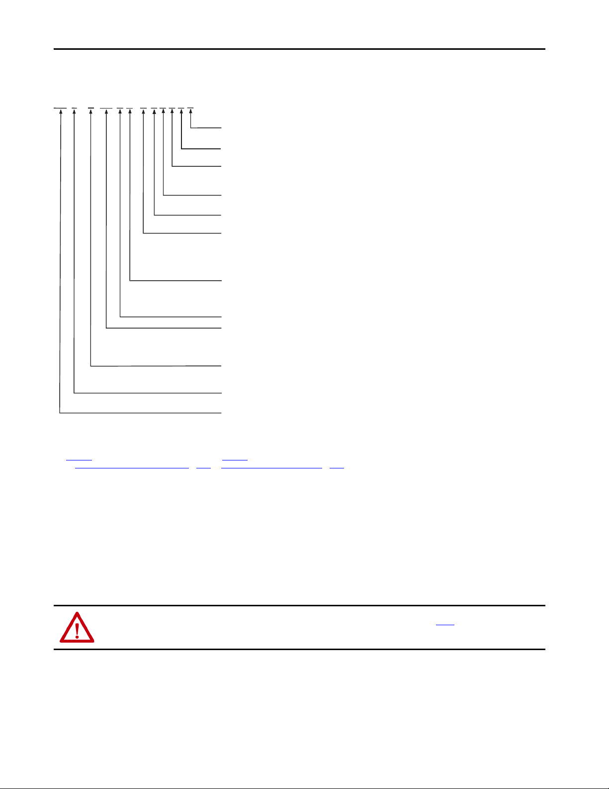
VP F - x xxx x x - x J 1 x A F
Factory Options
F= Food-grade shaft seal, Fluoroloy G4 (PTFE)
Mounting Flange
A = IEC metric, free mounting holes (type FF)
Brake
2 = No Brake
4 = 24V DC Brake
Shaft Key
J = Shaft key
Connector
1 = Single SpeedTec DIN connector, right angle, 315° rotatable
Feedback
C = 18-bit absolute single-turn digital encoder (Hiperface DSL protocol)
P = 18-bit absolute multi-turn (4096 revolutions) digital encoder (Hiperface DSL protocol)
Q = 23-bit absolute multi-turn digital encoder (Hiperface DSL protocol) SIL2/PLd rated, 12-bit secondary safety channel
(1)
W = 18-bit absolute multi-turn digital encoder (Hiperface DSL protocol) SIL2/PLd rated, 9-bit secondary safety channel
(2)
Rated Speed
(3)
A = 1500 rpm D = 3000 rpm M= 6000 rpm
B = 2000 rpm E = 3500 rpm T = 6750 rpm
C = 2500 rpm F = 4500 rpm U = 8000 rpm
Magnet Stack Length (1, 2, 3, 4 stacks)
(4)
Frame Size - Bolt Circle Diameter (BCD)
063 = 63 mm 115 = 115 mm
075 = 75 mm 130 = 130 mm
100 = 100 mm 165 = 165 mm
Voltage Class
A = 200V
B = 400V
Series Type
F = Food Grade enclosure (including food-grade shaft seal)
Series
VP = Permanent magnet rotary servo motors optimized to the ratings of Kinetix 5500 and Kinetix 5700 servo drives.
Catalog Number Explanation
(1) This encoder option is available with on ly VPF-A/B100xx, VPF-A/B115xx, VPF-A/B130xx, and VPF-B165xx motor frame sizes.
(2) This encoder option is available with only VPF-B063xx and VPF-B075xx motor frame sizes.
(3) Rated speed hierarchy is only for comparative purposes. Use Motion Analyzer software to size and select motors for your application, and/or the torque/speed curves in the Kinet ix 5500 Drive System Design Guide, publication
(4) See Motor Dimensions (063 mm and 075 mm frame sizes)
and the Kinetix 5700 Drive System Design Guide, publication KNX-RM010.
KNX-RM009
Before You Install the Motor
Perform these inspection steps and review the guidelines for shaft seals, couplings and pulleys, and electrical noise prevention.
1. Remove the motor carefully from its shipping container.
2. Inspect the motor for any damage.
3. Examine the motor frame, front output shaft, and mounting pilot for any defects.
4. Notify the carrier of shipping damage immediately.
ATTENTION: Do not attempt to open and modify the motor beyond changing the connector orientation as described on page 5. Only a qualified Rockwell
Automation employee can service this motor.
Remove the Shaft Cap
Remove the protective cap installed on the motor shaft with your hand or by prying it off with a screwdriver. Do not use a hammer or other tools as
they can damage the motor shaft.
2 Rockwell Automation Publication VPF-IN001C-EN-P - August 2016
on page 7 and Motor Dimensions (100…165 mm frame sizes) on page 8 for dimensional changes (L, LB, LD, and LE) that result from the number of magnet stacks.
Page 3
Kinetix VP Food Grade Servo Motors with 063…165 mm Frame Size
Prolong Motor Life
Proper design and maintenance can increase the life of a servo motor. Follow these guidelines to maximize the life of a servo motor that is operated
within the Environmental Specifications
• Create a drip loop in the single motor cable to carry liquids away from the connector.
• Whenever possible, provide shields that protect the motor housing, shaft, seals, and their junctions from contamination by foreign matter
or fluids.
• Shaft seals are subject to wear and require periodic inspection and replacement. Replacement is recommended every 3 months, not to
exceed 12 months, depending on use. See Shaft Seal Kits on page 21 for more information.
• Inspect the motor and seals for damage or wear regularly. If you detect damage or excessive wear, replace the item.
on page 21:
Shaft Seals
A shaft seal is required for Kinetix VP food-grade motors. An IP66 or IP67 rating for the motor requires a shaft seal and Bulletin 2090 cables with
environmentally sealed connectors.
See the following information on environmental ratings, shaft seals, and environmentally sealed connectors and cables compatible with the
KinetixVP food-grade motors:
•See Environmental Specifications
•See Shaft Seal Kits on page 21 for seal kits compatible with your motor.
• See Kinetix Rotary Motion Specifications Technical Data, publication KNX-TD001
connectors compatible with these motors.
on page 21 for a brief description of the IP ratings.
, for Bulletin 2090 cables with environmentally sealed
Couplings and Pulleys
Mechanical connections to the motor shaft, such as couplings and pulleys, require a torsionally rigid coupling or a reinforced timing belt. The high
dynamic performance of servo motors can cause couplings, pulleys, or belts to loosen or slip over time. A loose or slipping connection causes system
instability and can damage the motor shaft. All connections between the system and the servo motor shaft must be rigid to achieve acceptable
response from the system. Periodically inspect connections to verify their rigidity.
When mounting couplings or pulleys to the motor shaft, verify that the connections are properly aligned and that axial and radial loads are within
the specifications of the motor. See Load Force Ratings
ATTENTION: Damage can occur to the motor bearings a nd the feedback device if sharp impact is applied to the shaft during installation of couplings and pulleys.
Damage to the feedback device can result from applying leverage to the motor mounting face when removing any devices mounted on the motor shaft.
Do not strike the shaft, couplings, or pulleys with tools during installation or removal. Use a wheel puller to apply pressure from the user end of the shaft when
removing any device from the motor shaft.
on page 11 for guidelines to achieve 20,000 hours of motor bearing life.
Prevent Electrical Noise
Electromagnetic interference (EMI), commonly called electrical noise, can affect motor performance. Follow these guidelines to reduce the effects
of EMI:
• Isolate the power transformers or install line filters on all AC input power lines.
• Use shielded cables.
• Shield signal cables from power wiring.
• Do not route motor cables over the vent openings on servo drives.
• Ground all equipment by using a single-point parallel ground system that employs ground bus-bars or large straps.
• If necessary, use additional electrical-noise reduction techniques to reduce EMI in noisy environments.
See System Design for Control of Electrical Noise Reference Manual, publication GMC-RM001
, for more information on reducing EMI.
Install Cables
Proper cable routing and careful cable construction improves system electromagnetic compatibility (EMC).
ATTENTION: The overall shield on the single motor cable must be grounded to obtain an effective encoder signal. The encoder data signal is transmitted through
an impedance-matched twisted-wire pair that requires effective shielding for optimum performance. Make sure that there is an effective connection between
the cable shield and the drive system ground.
Rockwell Automation Publication VPF-IN001C-EN-P - August 2016 3
Page 4
Kinetix VP Food Grade Servo Motors with 063…165 mm Frame Size
To install the single motor cable, observe these guidelines:
• Keep the cable length as short as possible.
• Ground the cable shield to prevent EMI from affecting other equipment.
ATTENTION: High voltage can be present on the shields of the single motor cable if the shields are not grounded. Verify that there is a connection to ground for
all shields in the single motor cable.
Functional Safety
Motors that are equipped with a Hiperface DSL functional safety-rated feedback sensor are designed in compliance with the requirements of the
following SICK STEGMANN GmbH documentation to maintain the functional safety rating of the feedback sensor attached. See Catalog
Number Explanation on page 2 for details about each option.
Motor Cat. No. Feedbac k Sensor Function al-safety Reference Documentation (SICK STEGMANN GmbH)
VPF-xxxxxx-Q
VPF-xxxxxx-W EKM36-2 Safe Motor Feedback Systems Operating Instructions, publication 8019481/2016-02-23
HIPERFACE DSL Safety Manual, publication 8017596/YLR0
EFM50-2 Safe Motor Feedback Systems Operating Instructions, publication 8019321/2016-02-17
IMPORTANT
In accordance with the feedback sensor manufacturer, you must mount a HIPERFACE DSL motor feedback system (used for a safety function) in an
installation situation with a minimum protection class of IP54 according to standard IEC60529:1989 + A1:1999 + A2:2013.
Certification
The TÜV Rheinland group has approved Kinetix VP low-inertia servo motors equipped with functional-safety certified Hiperface DSL feedback
sensors to enable a system to be capable of achieving a functional safety rating up to Performance Level d (PLd) and safety category 3 (CAT. 3) per
EN ISO 13849, and SIL 2 per IEC 61508, EN 61800-5-2, and EN 62061 when used in conjunction with variable frequency drives that satisfy
functional safety requirements of the HIPERFACE DSL Safety Manual (SICK STEGMANN GmbH, publication 8017596/YLR0).
To view the TÜV Rheinland certificate and other product certifications currently available from Rockwell Automation, go to
http://www.rockwellautomation.com/global/certification/overview. page
.
Important Safety Considerations
In addition to following the instructions throughout this document, you are responsible for the following:
• Complete a machine-level risk assessment.
• Certification of the machine to the desired EN ISO 13849 performance level or EN 62061 SIL level.
• Project management and proof testing in accordance with EN 61800-5-2.
• The safe-motor feedback system has a maximum Mission Time of 20 years. After this time, the feedback system must be taken out of
service.
• The motor feedback system cannot support safety functions that are based on the absolute position without additional measures. In the ca se
of safety functions that are based on the safe absolute position, the motor feedback system supplies only one channel without safety-related
diagnostics upon powerup. You must implement a second channel by using other measures.
• The motor feedback system is not able to create a safe state for the drive system independently. The drive system creates the safe state as a
response to an error displayed by the motor feedback system.
• To plan and use motors equipped with safety-rated feedback sensors requires technical skills that are not explained in this document.
ATT EN TI ON : To avoid damage to the equipment, do not establish or remove electrical connections to the motor feedback system with the voltage switch ed on.
4 Rockwell Automation Publication VPF-IN001C-EN-P - August 2016
Page 5
Kinetix VP Food Grade Servo Motors with 063…165 mm Frame Size
Performance Level (PL) and Safety Integrity Level (SIL)
For safety-related control systems, Performance Level (PL), according to EN ISO 13849-1, and SIL levels, according to IEC EN 61508 and
EN 62061, include a rating of the system's ability to perform its safety functions. All of the safety related components of the control system must be
included in a risk assessment and the determination of the achieved levels.
Refer to the EN ISO 13849-1, IEC EN 61508, and EN 62061 standards for complete information on the requirements for PL and SIL
determination.
Safety Related Parameters
A motor that is equipped with a HIPERFACE DSL functional safety-rated feedback sensor is designed to maintain the functional safety rating of
the feedback sensor attached. The safety parameters of the feedback sensors are as follows.
Attribute
Safety Integrity Level (SIL) SIL2 (IEC 61508), SIL CL2 (EN 62061)
Probability of a Dangerous
Failure per Hour (PFH)
Safety Category CAT. 3 (EN ISO 13849)
Performance Level (PL) PLd (EN ISO 13849)
Motor Cat. No.
VPF-xxxxxx-WJ1xAF VPF-xxxxxx-QJ1xAF
4.0 E-08 1/h 3.80 E-08 1/h
Motor Installation
All motors include a mounting pilot for aligning the motor on a machine. Stainless steel fasteners are preferred. Stainless steel washers inserted
between the fastener head and motor flange are also recommended as a best mounting practice and are included with Bulletin VPF motors. Motor
installation must comply with all local regulations and use of equipment and installation practices that promote safety and electromagnetic
compatibility.
ATTENTION: To further protect the finish on the motor, it is recommended to insert stainless steel washers (smooth side on paint) between the fastener head
and motor flange. See the Mounting Flange Washer Kits
ATTENTION: Unmounted motors, disconnected mechanical couplings, loose shaft keys, and disconnected cables can be dangerous if power is applied. Identify
(tag-out) disassembled equipment and restrict access to (lock-out) the electrical power.
Before you apply power to the motor, remove the shaft key and other mechanical couplings that could be thrown from the shaft.
on page 22 for washer kit catalog numbers.
ATTENTION: Verify that cables are installed and restrained to prevent uneven tension or flexing at the connector. Provide support at 3 m (10ft) intervals
throughout the cable run.
Excessive and uneven lateral force at the cable connector can result in the environmental seal opening and closing as the cable flexes.
Change Connector Orientation
Kinetix VP food-grade motors use a connector style that integrates the power, brake, and feedback signals within one connector. You ca n i de nt if y
the connector style by the variable number in the motor catalog string. For example, in catalog number VPF-A1303F-CJ12AA, the 1 indicates a
SpeedTec, right-angle, 315° rotatable connector (see Catalog Number Explanation
The rotatable connector housing lets you move the connector into a position that best protects the connection from environmental contaminates
and provides easy access.
ATTENTION: Connectors are designed to be rotated into a fi xed position during motor installation, and remain in that position without further adjustment.
Strictly limit the applied forces and the number of times the connector is rotated to make sure that connectors meet the International Protection (IP) rating as
outlined in Environmental Specifications
on page 21.
Rockwell Automation Publication VPF-IN001C-EN-P - August 2016 5
on page 2).
Page 6
Kinetix VP Food Grade Servo Motors with 063…165 mm Frame Size
ATTENTION: Excessive force can damage the connector. Do not pull on the cable and do not use tools, such as pliers or vise-grips, to rotate the connector. Use
your hands to rotate the connector.
Follow these steps to rotate a connector to a new position.
1. Mount and fully seat a mating cable on the motor connector.
This step provides a larger area to grasp and extends the leverage force.
2. Grasp the mated connector and cable plug with your hands and slowly rotate the motor connector into the new position.
3. Remove the cable plug after the connector is aligned.
Install the Motor
Perform these steps to install the motor.
ATTENTION: Damage can occur to the motor bearings a nd the feedback device if sharp impact is applied to the shaft during installation of couplings and pulleys.
Damage to the feedback device can result from applying leverage to the motor mounting face when removing devices mounted on the motor shaft.
Do not strike the shaft, couplings, or pulleys with tools during installation or removal. Use a wheel puller, to apply pressure from the user end of the shaft, when
attempting to remove a ny device from the motor shaft.
1. Leave enough space around the motor so it can dissipate heat and stay within its specified operating temperature range.
See Environmental Specifications
across the motor for cooling. A fan that blows air across the motor improves its performance. Keep other heat-producing devices away from
the motor.
2. See Load Force Ratings
3. Install the motor with the connector positioned beneath the motor housing.
This position provides better environmental protection for the connector.
4. Mount and align the motor.
5. Attach the single motor cable that transmits the power, feedback, and brake signals as described in the following steps.
a. Carefully align the cable connector with the motor connector.
The flat surface on the top of the motor connector and the flat surfaces on the cable connector must align for the cable connector to
mate with the motor connector.
b. Hand-tighten the knurled collar one-quarter turn to fully seat the cable connector.
on page 11 to determine the maximum radial and axial shaft load ratings for your motor.
BURN HAZARD: Outer surfaces of the motor can reach a high temperature, 125 °C (257 °F), during motor operation.
Take precautions to prevent accidental contact with hot surfaces. Consider motor surface temperature when selecting the motor mating connections
and cables.
ATTENTION: Keyed connectors must be properly aligned and hand-tightened.
Do not use tools, or apply excessive force, when mating the cable to the motor connector. If the connectors do not go together with light hand force,
realign and try again.
on page 21 for the operating temperature range. Do not enclose the motor unless forced air is blown
ATTENTION: The overall shield on the single motor cable must be grounded to obtain an effective encoder signal.
The encoder data signal is transmitted through an impedance-matched twisted-wire pair that requires effective shielding for optimum performance.
Be sure that there is an effective connec tion between the single-motor cable shield and the drive system ground.
c. Form a drip loop in the cable to carry liquids away from the connectors.
6 Rockwell Automation Publication VPF-IN001C-EN-P - August 2016
Page 7
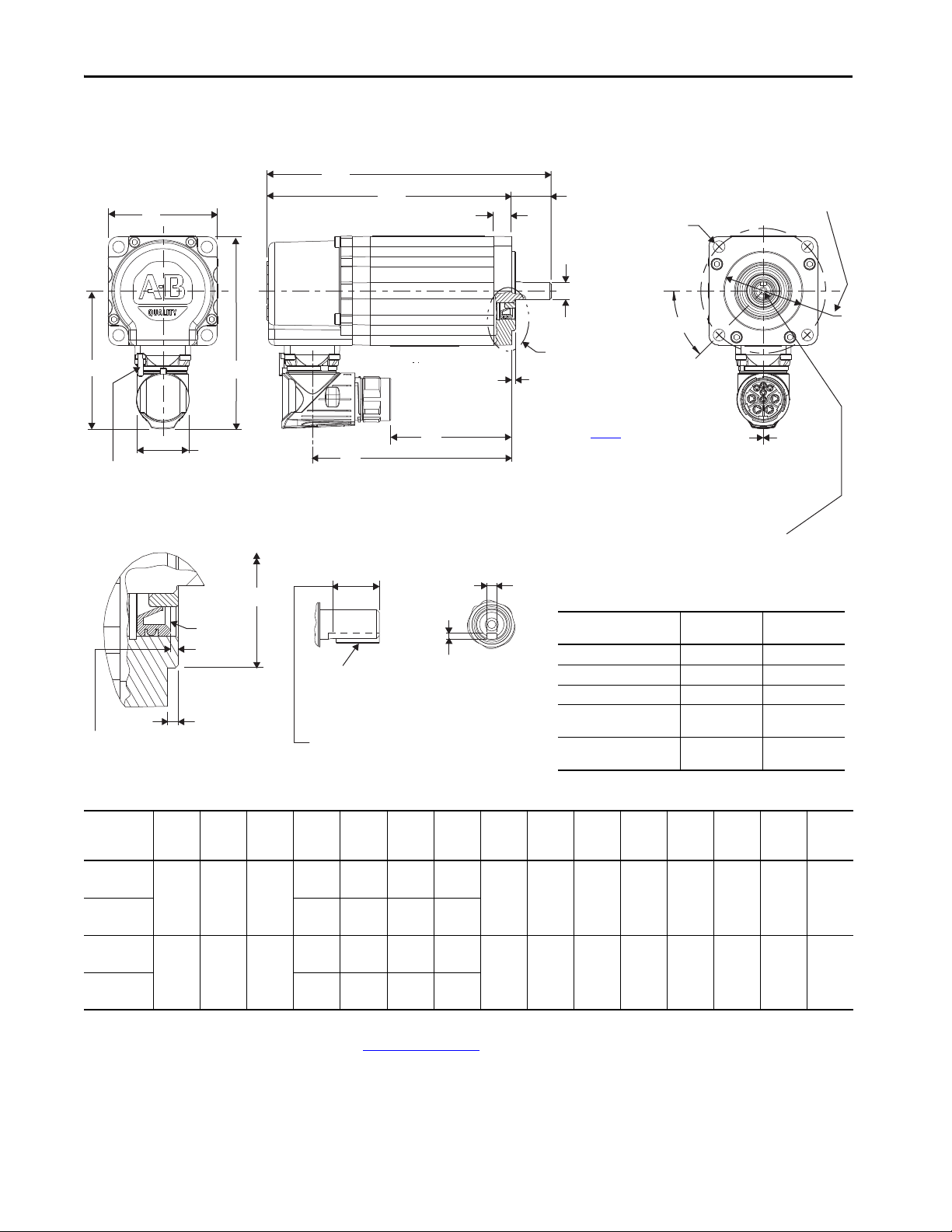
Motor Dimensions (063 mm and 075 mm frame sizes)
N
HD
P
26.6
(1.05)
AD
LA
LB
L-LB
L
D
LE
LD
F
GE
45°
See Detail A
Shaft Detail with Key
Shaft Diameter Tolerances
VPF-A/B063xx Motors: Ø 8.998…9.007 (0.3543…0.3546)
VPF-A/B075xx Motors: Ø 10,997…11.008 (0.4330…0.4334)
Detail A
Shaft
Diameter
Shaft Seal
Refer to page 21
for motor shaft seal kit
information.
Single (M23)
Motor Connector
S Diameter Holes on
M Diameter Bolt Circle
Dimensions are in mm (in.)
Shaft End Threaded Hole
VPF-A/B063xx Motors:
Thread - M3 x 0.5-6H
Thread Depth - 9.0 (0.354)
Connector housings can be
rotated within a range of 315°
Pilot Diameter Tolerances
VPF-A/B063xx Motors:
Ø 39.995…40.011 (1.5746…1.5752)
VPF-A/B075xx Motors:
Ø 59.993…60.012 (2.3619…2.3627)
Shaft, Pi lot, and Keyway
Tolerances
VPF-A/B063xx VPF-A/B075xx
Shaft Runout (T.I.R.) 0.030 (0.0012) 0.035 (0.0014)
Pilot Eccentricity (T.I.R.) 0.08 (0.0031) 0.08 (0.0031)
Max Face Runout (T.I.R.) 0.08 (0.0031) 0.08 (0.0031)
Keyway De pth (GE)
1.80…1.90
(0.071…0.075)
2.50…2.60
(0.098…0.102)
Keyway Widt h (F)
2.971…2.996
(0.117…0.118)
3.970…4.000
(0.156…0.158)
Key Supplied
VPF-A/B063xx = 3
(+0, -0.025)
x 3
(+0, -0.025)
x 13 Key
VPF-A/B075xx = 4
(+0, -0.030)
x 4
(+0, -0.030)
x 15 Key
Pilot Diameter (N)
Shaft Seal
Fully Developed Keyway Length
VPF-A/B063xx Motors: 14.0 (0.551)
VPF-A/B075xx Motors: 16.0 (0.630)
Pilot Height
2.1 (0.083)
Pilot Height
Shaft Seal Depth
1.5 ±0.13 (0.059 ±0.005)
Rotational
Stop
0° ±10° Shaft-end mark (or key)
orientation for encoder
absolute position = 0.
VPF-A/B075xx Motors:
Thread - M4 x 0.7-6H
Thread Depth - 10.0 (0.393)
Kinetix VP Food Grade Servo Motors with 063…165 mm Frame Size
Motor Dimensions (063 mm and 075 mm frame sizes)
(1) If ordering an VPF-A/B063xx or VPF-A/B075xx motor with brake, add 30.6 mm (1.20 in.) to dimension L, LB, LE, and LD.
(2) Tolerance for this dimension is ±0.7 mm (±0.028 in.).
(3) For keyway, shaft diameter, and pilot diameter tolerances, see the diagram or Shaft, Pilot, and Key way Tolerances table above.
(4) Tolerance for this dimension is 0.3, -0.0 mm (±0.006 in.).
Motors are designed to metric dimensions. Inch dimensions are approximate conversions from millimeters. Dimensions without tolerances are for
reference.
Motor
Cat. No.
VPF-A/B0632
VPF-A/B0633
VPF-A/B0752
VPF-A/B0753
AD
mm (in.)HDmm (in.)LAmm (in.)
69.5
97.0
(2.74)
(3.82)
77.0
(3.03)
112.0
(4.41)
9.0
(0.35)
9.0
(0.35)
P
mm (in.)
55.0
(2.17)
70.0
(2.76)
(1)
(1)
LD
mm (in.)
125.2
(4.93)
150.2
(5.91)
127.0
(5.00)
152.0
(5.98)
LE
mm (in.)
85.3
(3.36)
110.3
(4.34)
87.1
(3.43)
112.1
(4.41)
(1)
L
mm (in.)
168.1
(6.61)
193.1
(7.59)
172.9
(6.80)
197.9
(7.79)
(1)
LB
mm (in.)
148.1
(5.83)
173.1
(6.81)
149.9
(5.90)
174.9
(6.89)
(2)
L-LB
mm (in.)
(3)
D
mm (in.)
20.0
9.0
(0.354)
(0.787)
23.0
11.0
(0.906)
(0.433)
M
mm (in.)
63.0
(2.480)
(4)
S
mm (in.)
5.80
(0.234)
(3)
N
mm
(in.)
40.0
(1.575)
75.0
(2.953)
5.80
60.0
(0.234)
(2.362)
Rockwell Automation Publication VPF-IN001C-EN-P - August 2016 7
(3)
GE
mm (in.)
1.90
(0.075)
2.60
(0.102)
(3)
F
mm (in.)
3.0
(0.118)
4.0
(0.157)
Page 8
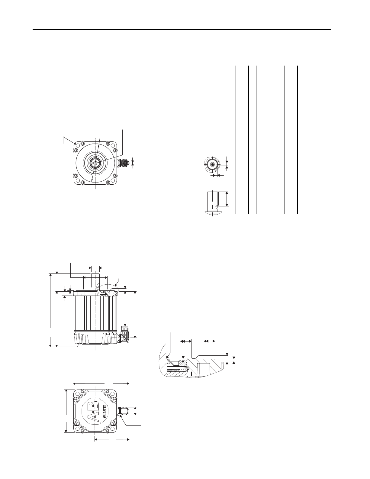
Kinetix VP Food Grade Servo Motors with 063…165 mm Frame Size
Shaft, Pilot, and Keyway
Tolerances
VPF-A/B100xx VPF-A/B115xx
VPF-A/B130xx
VPF-B165xx
Shaft Runout (T.I.R.) 0.04 (0.0016)
Pilot Eccentricity (T.I.R.) 0.078 (0.0031)
Max Face Runout (T.I.R.) 0.078 (0.0031)
Keyway Depth (GE)
3.00…3.10
(0.118…0.122)
3.50…3.60
(0.138…0.142)
4.00…4.20
(0.158…0.165)
Keyway Width (F)
4.97…5.00
(0.196…0.197)
5.97…6.00
(0.235…0.236)
7.96…8.00
(0.314…0.315)
See Detail A
Key Supplied
VPF-A/B100xx = 5
(+0, -0.030)
x 5
(+0, -0.030)
x 22 Key
VPF-A/B115xx = 6
(+0, -0.030)
x 6
(+0, -0.030)
x 24 Key
VPF-A/B130xx = 8
(+0, -0.036)
x 7
(+0, -0.090)
x 31 Key
VPF-B165xx = 8
(+0, -0.036)
x 7
(+0, -0.090)
x 39 Key
Shaft Detail with Key
VPF-A/B100xx = Ø 15.997…16.008 (0.6298…0.6302)
VPF-A/B115xx = Ø 18.996…19.009 (0.7479…0.7483)
VPF-A/B130xx = Ø 23.996…24.009 (0.9448…0.9451)
VPF-B165xx = Ø 27.996…28.009 (1.1022…1.1027)
Detail A
Shaft Diameter Tolerances
Shaft Diameter
S Diameter Holes on
M Diameter Bolt Circle.
Shaft End Threaded Hole
VPF-A/B100xx Motors:
Thread - M5 x 0.8-6H
Thread Depth - 12.5 (0.49)
VPF-A/B115xx Motors:
Thread - M6 x 1.0-6H
Thread Depth - 16.0 (0.63)
VPF-A/B130xx Motors:
Thread - M8 x 1.25-6H
Thread Depth - 19.1 (0.75)
VPF-B165xx Motors:
Thread - M10 x 1.5-6H
Thread Depth - 22.1 (0.87)
Shaft Seal
Refer to page 21
for Kinetix VP motor
shaft seal kit information.
Dimensions are in mm (in.)
Single Motor
Connector
Connector Housing
Rotates 315°
Pilot Relief Diameter
VPF-A/B100xx Motors = Ø 53.3 (2.10)
VPF-A/B115xx Motors = Ø 59.7 (2.35)
VPF-A/B130xx Motors = Ø 71.1 (2.80)
VPF-B165xx Motors = Ø 81.0 (3.19)
Keyway Length
VPF-A/B100xx = 25.4 (1.00)
VPF-A/B115xx = 25.4 (1.00)
VPF-A/B130xx = 32.3 (1.27)
VPF-B165xx = 41.1 (1.62)
Pilot Diameter (N)
Pilot Relief Diameter
Wear Sleeve Flush to Pilot Height
±0.83 (0.033)
Pilot Height
VPF-A/B100xx = 2.87 (0.113)
VPF-A/B115xx = 2.87 (0.113)
VPF-A/B130xx = 3.38 (0.133)
VPF-B165xx = 3.38 (0.133)
Pilot Relief Height (T)
Pilot Height
Pilot Diameter Tolerances
VPF-A/B100xx Motors:
Ø 79.993…80.012 (3.1493…3.1501)
VPF-A/B115xx Motors:
Ø 94.991…95.013 (3.7398…3.7407)
VPF-A/B130xx Motors:
Ø 109.991…110.013 (4.3303…4.3312)
VPF-B165xx Motors:
Ø 129.991…130.014 (5.1178…5.1187)
Rotational
Stop
Shaft Seal Depth
1.5 ±0.13 (0.059 ±0.005)
0° ±10° Shaft-end mark (or key)
orientation for encoder
absolute position = 0.
N
F
GE
L-LB
LA
LB
T
D
LD
LE
L
HD
26.6 (1.05)
P
Motor Dimensions (100…165 mm frame sizes)
8 Rockwell Automation Publication VPF-IN001C-EN-P - August 2016
AD
Motors are designed to metric dimensions. Inch dimensions are approximate conversions from millimeters. Dimensions without tolerances are for reference.
Page 9

(3)
(3)
F
GE
P
mm (in.)
mm (in.)
mm (in.)
Kinetix VP Food Grade Servo Motors with 063…165 mm Frame Size
6.0
(0.236)
8.0
4.0
113.7
(0.315)
(0.158)
(4.48)
8.0
4.0
143.5
(0.315)
(0.158)
(5.65)
5.0
(0.197)
3.5
3.0
(0.118)
89.4
(3.52)
(0.138)
98.3
(3.87)
(3)
(3)
(2)
(1)
(1)
(1)
N
S
M
D
L-LB
LB
L
LE
mm (in.)
mm (in.)
mm (in.)
mm (in.)
mm (in.)
mm (in.)
mm (in.)
mm (in.)
129.8
169.8
68.9
(5.11)
(6.68)
(2.71)
(4)
80.0
7.00
100.0
16.0
40.0
155.2
195.2
94.3
(3.15)
(0.283)
(3.937)
(0.630)
(1.575)
(6.11)
(7.68)
(3.71)
180.6
220.6
119.7
(7.11)
(8.68)
(4.71)
(4)
95.0
10.00
115.0
19.0
40.0
177.0
217.0
116.1
(3.74)
(0.401)
(4.528)
(0.748)
(1.575)
(6.97)
(8.54)
(4.57)
180.3
230.3
119.4
110.0
(4)
10.00
130.0
24.0
50.0
(7.10)
(9.06)
(4.70)
(4.331)
(0.401)
(5.118)
(0.945)
(1.969)
205.7
(8.10)
255.7
(10.06)
144.8
(5.70)
(5)
130.0
12.00
165.0
28.0
60.0
226.4
286.4
166.4
(5.118)
(0.481)
(6.496)
(1.102)
(2.362)
(8.92)
(11.27)
(6.55)
Motor Dimensions (100…165 mm frame sizes)
(1)
108.7
LD
LA
T
HD
AD
(4.28)
134.1
(5.28)
159.5
VPF-A/B1002
(6.28)
(0.39)
(0.108)
(5.17)
(3.40)
VPF-A/B1003
mm (in.)
mm (in.)
mm (in.)
mm (in.)
mm (in.)
Motor Cat. No.
9.90
2.74
131.2
86.5
VPF-A/B1001
156.0
10.16
2.74
140.0
90.8
(6.14)
(0.40)
(0.108)
(5.51)
(3.58)
VPF-A/B1153
159.3
(6.27)
184.7
(7.27)
206.2
(8.12)
12.19
(0.48)
14.0
(0.55)
2.74
(0.108)
3.12
(0.123)
155.4
(6.12)
185.0
(7.28)
98.6
(3.88)
113.3
(4.46)
If ordering a VPF-A/B115xx-xxx4xx motor with brake, add 48.5 mm (1.91 in.) to dimensions L, LB, LE, and LD.
If ordering a VPF-A/B130xx-xxx4xx motor with brake, add 48.5 mm (1.91 in.) to dimensions L, LB, LE, and LD.
VPF-A/B1303
VPF-A/B1304
VPF-B1652
If ordering a VPF-B165xx-xxx4xx motor with brake, add 51.5 mm (2.03 in.) to dimensions L, LB, LE, and LD.
(1) If ordering a VPF-A/B100xx-xxx4xx motor with brake, add 34.5 mm (1.36 in.) to dimensions L, LB, LE, and LD.
(2) Tolerance for this dimension is ±0.7 mm (±0.028 in.).
(3) For keyway, shaft diameter, and pilot diameter tolerances, see the diagram or Shaft, Pi lot, and Keyway Tolerances table on page 8.
Motors are designed to metric dimensions. Inch dimensions are approximate conversions from millimeters. Dimensions without tolerances are for reference.
(4) Tolerance for this dimension is +0.36, -0.0 mm (±0.007 in.).
(5) Tolerance for this dimension is +0.43 -0.0 mm (±0.008 in.).
Rockwell Automation Publication VPF-IN001C-EN-P - August 2016 9
Page 10

Kinetix VP Food Grade Servo Motors with 063…165 mm Frame Size
Connector Data
This section identifies the power, feedback, and brake pins on the motor connector.
M23 Motor Connector Pinouts
Pin High-resolution Encoder
A Phase U
B Phase V
C Phase W
Ground
E DATA+
F MBRK+
G MBRK-
H DATA-
L Reserved
BC
A
G
F
LE
H
10 Rockwell Automation Publication VPF-IN001C-EN-P - August 2016
Page 11

Kinetix VP Food Grade Servo Motors with 063…165 mm Frame Size
Axial load force that is applied to the center of the shaft.
Radial load force that is applied at the midpoint of the shaft extension.
Load Force Ratings
Motors can operate with a sustained shaft load. The location and direction of radial and axial load forces are shown in the figure, and maximum
load-rating values are in the tables.
Load Forces on Shaft
The following tables represent 20,000-hour L10 bearing fatigue life at various loads and speeds. This 20,000-hour bearing life does not account for
possible application-specific life reduction, such as bearing grease contamination from external sources.
Kinetix Food Grade Motors (063 mm and 075 mm frame size)
Radial Load Force Ratings (maximum) for Non-brake Motors
Motor
Cat. No.
VPF-A0632F 4800 – 28.9 25.2 – – 21 .0 * – – – 17.1 * – – – – –
VPF-A0633C3000 38.130.327.4 *––21.0–––––––––
VPF-A0633F4500 38.1–26.4––21.0––18.3––––––
VPF-A0752C3300 36.128.625.9 *–––19.2 *––––––––
VPF-A0752E 4800 36.1 28.6 – – 21.8 * – – – – 17.0 * – – – – –
VPF-A0753C3300 37.830.027.5 *–––20.2 *––––––––
VPF-A0753E 4600 37.8 30.0 – – 23.3 * – – – – 18.0 * – – – – –
VPF-B0632F 4800 – 28.9 25.2 – – 21.0 * – – – 17.1 * – – – – –
VPF-B0632T 8000 – – – 22.9 – – – 18.2 – – – 15.6 * – – 14.4
VPF-B0633M6900 –30.3–24.0–––19.2 *––––15.9 *––
VPF-B0633T 8000 – – 26.4 – – 21.0 – – – – 16.8 * – – – 15.1
VPF-B0752E 4800 36.1 28.6 – – 22.0 * – – – – 17.0 * – – – – –
VPF-B0752F7000 –28.6–22.7––19.3 *–––––15.0––
VPF-B0752M 8000 – – 25.0 – – 20.8 – – – 16.8 * – – – – 14.3
VPF-B0753E4500 37.830.0–23.8––––18.2––––––
VPF-B0753F 6500 – 30.0 – 23.8 – 20.6 * – – – – 16.1 – – –
VPF-B0753M 8000 – – 26.2 – – 19.8 – – – 18.0 * – – – – 15.0
(1) 1.0 kgf = 2.2 lbf or 9.8 N. An asterisk (*) indicates a load rating that is measured at an rpm value that is less than the value listed for that column.
(1)
Speed, max
rpm
500
kgf
1000
kgf
1500
kgf
2000
kgf
2500
kgf
3000
kgf
3500
kgf
4000
kgf
RPM
4500
kgf
5000
kgf
6000
kgf
6500
kgf
7000
kgf
7500
kgf
8000
kgf
Rockwell Automation Publication VPF-IN001C-EN-P - August 2016 11
Page 12

Kinetix VP Food Grade Servo Motors with 063…165 mm Frame Size
Axial Load Force Ratings (maximum radial load) for Non-brake Motors
Motor
Cat. No.
VPF-A0632F4800 –23.519.7––15.5 *–––11.9 *–––––
VPF-A0633C3000 32.724.221.3 *––15.0–––––––––
VPF-A0633F4500 32.7–20.3––15.0––12.6––––––
VPF-A0752C3300 31.523.320.5 *–––13.9 *––––––––
VPF-A0752E4800 31.523.3––16.4 *––––11.8 *–––––
VPF-A0753C3300 32.524.121.5 *–––14.3 *––––––––
VPF-A0753E4600 32.524.1––17.3 *––––12.4 *–––––
VPF-B0632F4800 –23.519.7––15.5 *–––11.9 *–––––
VPF-B0632T8000 –––17.4–––12.9–––10.6––9.5
VPF-B0633M 6900 – 24.2 – 17.9 – – – 13.4 * – – – – 10.5 * – –
VPF-B0633T8000 ––20.3––15.0––––11.3 *–––9.8
VPF-B0752E4800 31.523.3––16.6 *––––11.8 *–––––
VPF-B0752F7000 –23.3–17.3––14.0 *–––––10.0––
VPF-B0752M8000 ––19.6––14.5–––11.7 *––––9.5
VPF-B0753E4500 32.524.1–17.8––––12.5––––––
VPF-B0753F6500 –24.1–17.8––14.7 *––––10.7–––
VPF-B0753M8000 ––20.2––14.9–––12.4 *––––9.8
(1) 1.0 kgf = 2.2 lbf or 9.8 N. An asterisk (*) indicates a load rating that is measured at an rpm value that is less than the value listed for that column.
(1)
Speed, max
rpm
500
kgf
1000
kgf
1500
kgf
2000
kgf
2500
kgf
3000
kgf
3500
kgf
RPM
4000
kgf
4500
kgf
5000
kgf
6000
kgf
6500
kgf
7000
kgf
7500
kgf
8000
kgf
Axial Load Force Ratings (zero radial load) for Non-brake Motors
RPM
4000
kgf
4500
kgf
5000
kgf
6000
kgf
6500
kgf
7000
kgf
7500
kgf
8000
kgf
(1)
Speed, max
rpm
500
kgf
1000
kgf
1500
kgf
2000
kgf
2500
kgf
3000
kgf
3500
kgf
Motor
Cat. No.
VPF-A0632F4800 –27.523.0––18.1 *–––13.9 *–––––
VPF-A0633C3000 37.127.524.1 *––17.1–––––––––
VPF-A0633F4500 37.1–23.0––17.1––14.3––––––
VPF-A0752C3300 37.127.524.1 *–––16.4 *––––––––
VPF-A0752E4800 37.127.5––19.3 *––––13.9 *–––––
VPF-A0753C3300 37.127.524.5 *–––16.4 *––––––––
VPF-A0753E4600 37.127.5––19.7 *––––14.2 *–––––
VPF-B0632F4800 –27.523.0––18.1 *–––13.9 *–––––
VPF-B0632T8000 –––20.3–––15.1–––12.4 *––11.1
VPF-B0633M 6900 – 27.5 – 20.3 – – – 15.2 * – – – – 11.9 * – –
VPF-B0633T8000 ––23.0––17.1––––12.8 *–––11.1
VPF-B0752E4800 37.127.5––19.5 *––––13.9 *–––––
VPF-B0752F7000 –27.5–20.3––16.5 *–––––11.8––
VPF-B0752M8000 ––23.0––17.1–––13.8 *––––11.1
VPF-B0753E4500 37.127.5–20.3––––14.3––––––
VPF-B0753F6500 –27.5–20.3––16.8 *––––12.2–––
VPF-B0753M8000 ––23.0––17.1–––14.2 *––––11.1
(1) 1.0 kgf = 2.2 lbf or 9.8 N. An asterisk (*) indicates a load rating that is measured at an rpm value that is less than the value listed for that column.
12 Rockwell Automation Publication VPF-IN001C-EN-P - August 2016
Page 13

Radial Load Force Ratings (maximum) for Brake Motors
Kinetix VP Food Grade Servo Motors with 063…165 mm Frame Size
Motor
Cat. No.
VPF-A0632F4800 –30.526.6––22.2 *–––18.1 *–––––
VPF-A0633C3000 39.531.428.4 *––21.8–––––––––
VPF-A0633F4500 39.5–27.4––21.8––19.0––––––
VPF-A0752C3300 38.130.327.4–––20.3 *––––––––
VPF-A0752E4800 38.130.3––23.1 *––––17.9 *–––––
VPF-A0753C3300 39.231.228.5 *–––20.9 *––––––––
VPF-A0753E4600 39.231.2––24.1 *––––18.7 *–––––
VPF-B0632F4800 –30.526.6––22.2 *–––18.1 *–––––
VPF-B0632T8000 –––24.2–––19.2–––16.5 *––15.3
VPF-B0633M 6900 – 31.4 – 24.9 – – – 19.9 * – – – – 16.5 * – –
VPF-B0633T8000 ––27.4––21.8––––17.5 *–––15.7
VPF-B0752E4800 38.130.3––23.3 *––––17.9 *–––––
VPF-B0752F7000 –30.3–24.0––20.4 *–––––15.8––
VPF-B0752M8000 ––26.4––21.0–––17.8 *––––15.1
VPF-B0753E4500 39.231.2–24.7––––18.9––––––
VPF-B0753F6500 –31.2–24.7––21.4 *––––16.7–––
VPF-B0753M8000 ––27.2––21.6–––18.7 *––––15.6
(1) 1.0 kgf = 2.2 lbf or 9.8 N. An asterisk (*) indicates a load rating that is measured at an rpm value that is less than the value listed for that column.
(1)
Speed, max
rpm
500
kgf
1000
kgf
1500
kgf
2000
kgf
2500
kgf
3000
kgf
3500
kgf
RPM
4000
kgf
4500
kgf
5000
kgf
6000
kgf
6500
kgf
7000
kgf
7500
kgf
8000
kgf
Axial Load Force Ratings (maximum radial load) for Brake Motors
RPM
4000
kgf
4500
kgf
5000
kgf
6000
kgf
6500
kgf
7000
kgf
7500
kgf
8000
kgf
(1)
Speed, max
rpm
500
kgf
1000
kgf
1500
kgf
2000
kgf
2500
kgf
3000
kgf
3500
kgf
Motor
Cat. No.
VPF-A0632F4800 –24.320.4––16.1 *–––12.3 *–––––
VPF-A0633C3000 33.524.821.8 *––15.4–––––––––
VPF-A0633F4500 33.5–20.8––15.4––12.9––––––
VPF-A0752C3300 32.724.221.3 *– –14.4 *––––––––
VPF-A0752E4800 32.724.2––17.0 *––––12.3 *–––––
VPF-A0753C3300 33.424.722.0 *– –14.7 *––––––––
VPF-A0753E4600 33.424.7––17.7 *––––12.7 *–––––
VPF-B0632F4800 –24.320.4––16.1 *–––12.3 *–––––
VPF-B0632T8000 –––18.0–––13.3–––11.0 *––9.9
VPF-B0633M 6900 – 24.8 – 18.4 – – – 13.7 * – – – – 10.7 * – –
VPF-B0633T8000 ––20.8––15.4––––11.6 *–––10.1
VPF-B0752E4800 32.724.2––17.2 *––––12.3 *–––––
VPF-B0752F7000 –24.2–17.9––14.5 *–––––10.4––
VPF-B0752M8000 ––20.3––15.0–––12.1 *––––9.8
VPF-B0753E4500 33.424.7–18.3––––12.9––––––
VPF-B0753F6500 –24.7–18.3––15.1 *––––11.0–––
VPF-B0753M8000 ––20.7––15.3–––12.7 *––––10.0
(1) 1.0 kgf = 2.2 lbf or 9.8 N. An asterisk (*) indicates a load rating that is measured at an rpm value that is less than the value listed for that column.
Rockwell Automation Publication VPF-IN001C-EN-P - August 2016 13
Page 14

Kinetix VP Food Grade Servo Motors with 063…165 mm Frame Size
Axial Load Force Ratings (zero radial load) for Brake Motors
Motor
Cat. No.
VPF-A0632F4800 –27.523.0––18.1 *–––13.9 *–––––
VPF-A0633C3000 37.127.524.1 *––17.1–––––––––
VPF-A0633F4500 37.1–23.0––17.1––14.3––––––
VPF-A0752C3300 37.127.524.1 *–––16.4 *––––––––
VPF-A0752E4800 37.127.5––19.3 *––––13.9 *–––––
VPF-A0753C3300 37.127.524.5 *–––16.4 *––––––––
VPF-A0753E4600 37.127.5––19.7 *––––14.2 *–––––
VPF-B0632F4800 –27.523.0––18.1 *–––13.9 *–––––
VPF-B0632T8000 –––20.3–––15.1–––12.4 *––11.1
VPF-B0633M 6900 – 27.5 – 20.3 – – – 15.2 * – – – – 11.9 * – –
VPF-B0633T8000 ––23.0––17.1––––12.8 *–––11.1
VPF-B0752E4800 37.127.5––19.5 *––––13.9 *–––––
VPF-B0752F7000 –27.5–20.3––16.5 *–––––11.8––
VPF-B0752M8000 ––23.0––17.1–––13.8 *––––11.1
VPF-B0753E4500 37.127.5–20.3––––14.3––––––
VPF-B0753F6500 –27.5–20.3––16.8 *––––12.2–––
VPF-B0753M8000 ––23.0––17.1–––14.2 *––––11.1
(1) 1.0 kgf = 2.2 lbf or 9.8 N. An asterisk (*) indicates a load rating that is measured at an rpm value that is less than the value listed for that column.
(1)
Speed, max
rpm
500
kgf
1000
kgf
1500
kgf
2000
kgf
2500
kgf
3000
kgf
3500
kgf
RPM
4000
kgf
4500
kgf
5000
kgf
6000
kgf
6500
kgf
7000
kgf
7500
kgf
8000
kgf
14 Rockwell Automation Publication VPF-IN001C-EN-P - August 2016
Page 15

Kinetix VP Food Grade Motors (100…165 mm frame sizes)
Radial Load Force Ratings (maximum) for Non-brake Motors
Kinetix VP Food Grade Servo Motors with 063…165 mm Frame Size
Motor
Cat. No.
VPF-A1001C 2800 79.1 – 62.8 – 49.8 – 44.6 * – – – – – – – –
VPF-A1001M 6500 – – – 54.9 – 46.3 – – – 38.0 – – – 33.6 –
VPF-A1002C 3000 87.9 – 69.7 – 55.4 – 48.4 – – – – – – – –
VPF-A1002F 5000 – – 69.7 60.9 – – 48.4 – – – 40.8 – – – –
VPF-A1003C 2250 93.6 – 74.3 64.9 – 56.7 * – – – – – – – – –
VPF-A1003E 3750 93.6 – 74.3 – 59.0 – – – 47.8 * – – – – – –
VPF-A1003F 5500 – – – 6 4.9 – 54.8 – – 46.8 – – 4 2.1 – – –
VPF-A1153C 2300 106.4 – 84.5 73.8 – 64.0 * – – – – – – – – –
VPF-A1303B 1950 132.9 – 105.5 92.2 84.4 * – – – – – – – – – –
VPF-A1303F 4000 – – 105.5 – 83.7 – 73.1 – 66.5 – – – – –
VPF-A1304A 1600 140.2 122.5 112.2 * – 95.2 * – – – – – – – – – –
VPF-A1304D 3000 140.2 – 111.3 – 88.3 – 77.2 – – – – – – – –
VPF-B1001M 6000 – – – – 49.8 – 43.5 – 39.6 – – – 34.6 – –
VPF-B1002E 3300 87.9 – 69.7 – 55.4 – – 46.8 * – – – – – – –
VPF-B1002M 6000 – – – 6 0.9 – – 48.4 – – 42.2 – – 38.4 – –
VPF-B1003C 2500 93.6 – 74.3 64.9 – 54.8 – – – – – – – – –
VPF-B1003F 4750 – – 74.3 64.9 – – 51.5 – – – 44.2 * – – – –
VPF-B1003T 7000 – – – 64.9 – 54.8 – – – 45.0 – – – – 38.9
VPF-B1153E 3200 106.4 – 84.5 – 67.0 – – 57.3 * – – – – – – –
VPF-B1153F 5000 – – 84.5 – 67.0 – 58.6 – – – 49.4 – – – –
VPF-B1303C 2250 132.9 – 105.5 92.2 – 80.5 * – – – – – – – – –
VPF-B1303F 4000 – – 105.5 – 83.7 – 74.0 * – 66.5 – – – – – –
VPF-B1304C 2150 140.2 – 111.3 99.5 * – 86.2 * – – – – – – – – –
VPF-B1304E 3500 – – 111.3 97.2 – 84.3 * – 73.3 – – – – – – –
VPF-B1652C 2700 180.7 – 143.4 125.3 – – 103.0 * – – – – – – – –
(1) 1.0 kgf = 2.2 lbf or 9.8 N. An asterisk (*) indicates a load rating that is measured at an rpm value that is less than the value listed for that column.
(1)
Speed, max
rpm
500
kgf
750
kgf
1000
kgf
1500
kgf
2000
kgf
2500
kgf
3000
kgf
3500
kgf
RPM
4000
kgf
4500
kgf
5000
kgf
5500
kgf
6000
kgf
6500
kgf
7000
kgf
Rockwell Automation Publication VPF-IN001C-EN-P - August 2016 15
Page 16

Kinetix VP Food Grade Servo Motors with 063…165 mm Frame Size
Axial Load Force Ratings (maximum radial load) for Non-brake Motors
Motor
Cat. No.
VPF-A1001C 2800 25.0 –19.0 –10.0 –10.0 *––––––––
VPF-A1001M 6500 –––15.0 –12.0 –––9.0 –––8.0 –
VPF-A1002C 3000 30.0 –22.0 –16.0 –13.0 ––––––––
VPF-A1002F 5000 ––22.0 18.0 ––13.0 –––11.0 ––––
VPF-A1003C2250 33.0 –24.0 20.0 –17.0 *–––––––––
VPF-A1003E3750 33.0 –24.0 –18.0 –––13.0 *––––––
VPF-A1003F 5500 – – – 20.0 – 16.0 – – 13.0 – – 11.0 – – –
VPF-A1153C 2300 48.0 –35.0 29.0 –24.0 *–––––––––
VPF-A1303B1950 39.0 –29.024.022.0 *––––––––––
VPF-A1303F4000 ––29.0 –21.0–18.0–16.0 ––––––
VPF-A1304A1600 43.0 36.032.0 *–26.0 *––––––––––
VPF-A1304D 3000 43.0 –32.0 –23.0 –20.0 ––––––––
VPF-B1001M 6000 – – – – 14.0 – 11.0 – 10.0 – – – 8.0 – –
VPF-B1002E 3300 30.0 –22.0 –16.0 ––13.0 *–––––––
VPF-B1002M 6000 – – – 18.0 – – 13.0 – – 11.0 – – 10.0 – –
VPF-B1003C2500 33.0 –24.0 20.0–16.0 –––––––––
VPF-B1003F4750 ––24.0 20.0––15.0–––12.0 * ––––
VPF-B1003T 7000 –––20.0 –16.0 –––12.0––––10.0
VPF-B1153E 3200 48.0 –35.0 –26.0––21.0 * –––––––
VPF-B1153F 5000 ––35.0 –26.0–22.0 –––17.0––––
VPF-B1303C 2250 39.0 –29.0–24.020.0 *–––––––––
VPF-B1303F 4000 ––29.0–21.0 –18.0 *–16.0 ––––––
VPF-B1304C 2150 43.0–32.0 27.0 *–23.0 *–––––––––
VPF-B1304E 3500 ––32.0 27.0 –22.0 *–18.0 –––––––
VPF-B1652C 2700 58.0–43.0 36.0 ––27.0 * ––––––––
(1) 1.0 kgf = 2.2 lbf or 9.8 N. An asterisk (*) indicates a load rating that is measured at an rpm value that is less than the value listed for that column.
(1)
Speed, max
rpm
500
kgf
750
kgf
1000
kgf
1500
kgf
2000
kgf
2500
kgf
3000
kgf
RPM
3500
kgf
4000
kgf
4500
kgf
5000
kgf
5500
kgf
6000
kgf
6500
kgf
7000
kgf
16 Rockwell Automation Publication VPF-IN001C-EN-P - August 2016
Page 17

Axial Load Force Ratings (zero radial load) for Non-brake Motors
Kinetix VP Food Grade Servo Motors with 063…165 mm Frame Size
Motor
Cat. No.
VPF-A1001C 2800 49.4 –36.5 –27.0 –23.4 *––––––––
VPF-A1001M 6500 – – – 30.6 – 24.5 – – – 19.0 – – – 16.2 –
VPF-A1002C 3000 49.4 –36.5 – 27.0 – 22.7 ––––––––
VPF-A1002F 5000 ––36.5 30.6 ––22.7 –––18.2 ––––
VPF-A1003C2250 49.4 –36.5 30.6–25.7 *–––––––––
VPF-A1003E3750 49.4 –36.5 –27.0 –––20.6 *––––––
VPF-A1003F 5500 – – – 30.6 – 24.5 – – 20.0 – – 17.4 – – –
VPF-A1153C 2300 68.3–50.5 42.4 35.2 *–––––––––
VPF-A1303B1950 68.3–50.5 42.437.8 *––––––––––
VPF-A1303F4000 ––50.5 –37.4–31.4–27.7 ––––––
VPF-A1304A1600 68.357.2 51.1 *–41.2 *––––––––––
VPF-A1304D 3000 68.3–50.5 –37.4 –31.4––––––––
VPF-B1001M 6000 – – – – 27.0 – 22.7 – 20.0 – – – 16.8 – –
VPF-B1002E 3300 49.4 – 36.5 – 27.0 – – 21.8 * – – – – – –
VPF-B1002M 6000 – – – 30.6 – – 22.7 – – 19.0 – – 16.8 – –
VPF-B1003C2500 49.4 –36.5 30.6–24.5 –––––––––
VPF-B1003F4750 ––36.5 30.6 ––22.7–––18.6 *––––
VPF-B1003T 7000 –––30.6 –24.5 –––19.0––––15.7
VPF-B1153E 3200 68.3–50.5–37.4 ––30.5 *–––––––
VPF-B1153F 5000 ––50.5 –37.4–31.4–––25.1 ––––
VPF-B1303C 2250 68.3–50.542.3–35.5 *–––––––––
VPF-B1303F 4000 ––50.5 –37.4–31.8 *–27.7 ––––––
VPF-B1304C 2150 68.3–50.5 43.6 *–36.2 *–––––––––
VPF-B1304E 3500 ––50.542.4–35.2 *–29.3 –––––––
VPF-B1652C 2700 90.1–66.7 55.9 ––43.3 *––––––––
(1) 1.0 kgf = 2.2 lbf or 9.8 N. An asterisk (*) indicates a load rating that is measured at an rpm value that is less than the value listed for that column.
(1)
Speed, max
rpm
500
kgf
750
kgf
1000
kgf
1500
kgf
2000
kgf
2500
kgf
3000
kgf
RPM
3500
kgf
4000
kgf
4500
kgf
5000
kgf
5500
kgf
6000
kgf
6500
kgf
7000
kgf
Rockwell Automation Publication VPF-IN001C-EN-P - August 2016 17
Page 18

Kinetix VP Food Grade Servo Motors with 063…165 mm Frame Size
Radial Load Force Ratings (maximum) for Brake Motors
Motor
Cat. No.
VPF-A1001C 2800 90.2–71.6–56.8–50.8 *––––––––
VPF-A1001M 6500 – – – 62.5 – 52.7 – – – 43.4 – – – 38.4 –
VPF-A1002C 3000 95.3–75.6–60.0–52.4––––––––
VPF-A1002F 5000 ––75.666.1––52.4–––44.2––––
VPF-A1003C2250 99.0–78.568.6–59.9 *–––––––––
VPF-A1003E3750 99.0–78.5–62.3–––50.6 *––––––
VPF-A1003F 5500 – – – 68.6 – 57.9 – – 49.5 – – 44.5 – – –
VPF-A1153C 2300 115.4–91.680.0–69.4 *–––––––––
VPF-A1303B1950 145.3–115.3100.792.3 *––––––––––
VPF-A1303F 4000 ––115.3–91.5–80.0–72.7––––––
VPF-A1304A 1 600 149.7 130.8 119.8 * – 101.6 * ––––––––––
VPF-A1304D 3000 149.5–118.6–94.2–82.3––––––––
VPF-B1001M 6000 – – – – 56.8 – 49.6 – 45.1 – – – 39.4 – –
VPF-B1002E 3300 95.3–75.6–60.0––50.8 *–––––––
VPF-B1002M 6000 – – – 66.1 – – 52.4 – – 45.8 – – 41.6 – –
VPF-B1003C2500 99.0–78.568.6–57.9–––––––––
VPF-B1003F4750 ––78.568.6– 54.5–––46.7 *––––
VPF-B1003T 7000 –––68.6–57.9–––47.6––––41.1
VPF-B1153E 3200 115.4–91.6–72.7––62.2 *–––––––
VPF-B1153F 5000 ––91.6–72.7–63.5–––53.6––––
VPF-B1303C 2250 145.3–115.3100.7 –88.0 *–––––––––
VPF-B1303F 4000 ––115.3–91.5–80.9 *–72.7––––––
VPF-B1304C 2150 149.7–118.8106.2 *–92.0 *–––––––––
VPF-B1304E 3500 ––118.8103.8–90.0 *–78.2–––––––
VPF-B1652C 2700 192.5 –152.8 133.5 ––109.7 *––––––––
(1) 1.0 kgf = 2.2 lbf or 9.8 N. An asterisk (*) indicates a load rating that is measured at an rpm value that is less than the value listed for that column.
(1)
Speed, max
rpm
500
kgf
750
kgf
1000
kgf
1500
kgf
2000
kgf
2500
kgf
3000
kgf
RPM
3500
kgf
4000
kgf
4500
kgf
5000
kgf
5500
kgf
6000
kgf
6500
kgf
7000
kgf
18 Rockwell Automation Publication VPF-IN001C-EN-P - August 2016
Page 19

Axial Load Force Ratings (maximum radial load) for Brake Motors
Kinetix VP Food Grade Servo Motors with 063…165 mm Frame Size
Motor
Cat. No.
VPF-A1001C 2800 31.0 –23.0 –17.0 –14.0 *––––––––
VPF-A1001M 6500 – – – 19.0 – 15.0 – – – 12.0 – – – 10.0 –
VPF-A1002C 3000 34.0 –25.0 –18.0 –15.0 ––––––––
VPF-A1002F 5000 ––25.0 21.0––15.0 –––12.0 ––––
VPF-A1003C2250 36.0 –26.022.0 –18.0 *–––––––––
VPF-A1003E3750 36.0 –26.0 –19.0 –––15.0 *––––––
VPF-A1003F 5500 – – – 22.0 – 18.0 – – 14.0 – – 12.0 – – –
VPF-A1153C 2300 53.0 –39.0 32.0 –27.0 *–––––––––
VPF-A1303B1950 46.0 –34.0 28.0 25.0 *––––––––––
VPF-A1303F4000 ––34.0 –25.0–21.0 –18.0 ––––––
VPF-A1304A1600 48.0 40.0 36.0 *–29.0 *––––––––––
VPF-A1304D 3000 48.0 –36.0 –26.0–22.0 ––––––––
VPF-B1001M 6000 – – – – 17.0 – 14.0 – 12.0 – – – 10.0 – –
VPF-B1002E 3300 34.0 –25.0 –18.0 ––15.0 *–––––––
VPF-B1002M 6000 – – – 21.0 – – 15.0 – – 13.0 – – 11.0 – –
VPF-B1003C2500 36.0 –26.0 22.0–18.0–––––––––
VPF-B1003F4750 ––26.022.0––16.0 –––13.0 *––––
VPF-B1003T 7000 –––22.0 –18.0 –––13.0 ––––11.0
VPF-B1153E 3200 53.0 –39.0 –29.0 ––23.0*–––––––
VPF-B1153F 5000 ––39.0 –29.0 –24.0 –––19.0 ––––
VPF-B1303C 2250 46.0–34.0 28.0–24.0 *–––––––––
VPF-B1303F 4000 ––34.0 –25.0 –21.0 *–18.0 ––––––
VPF-B1304C 2150 48.0 –36.0 31.0 *–25.0 *–––––––––
VPF-B1304E 3500 ––36.030.0–25.0 *–20.0 –––––––
VPF-B1652C 2700 64.0 –47.0 39.0 ––30.0 *––––––––
(1) 1.0 kgf = 2.2 lbf or 9.8 N. An asterisk (*) indicates a load rating that is measured at an rpm value that is less than the value listed for that column.
(1)
Speed, max
rpm
500
kgf
750
kgf
1000
kgf
1500
kgf
2000
kgf
2500
kgf
3000
kgf
RPM
3500
kgf
4000
kgf
4500
kgf
5000
kgf
5500
kgf
6000
kgf
6500
kgf
7000
kgf
Rockwell Automation Publication VPF-IN001C-EN-P - August 2016 19
Page 20

Kinetix VP Food Grade Servo Motors with 063…165 mm Frame Size
Axial Load Force Ratings (zero radial load) for Brake Motors
Motor
Cat. No.
VPF-A1001C 2800 49.4 – 36.5 – 27.0 – 23.4 * – – – – – – – –
VPF-A1001M 6500 – – – 30.6 – 24.5 – – – 19.0 – – – 16.2 –
VPF-A1002C 3000 49.4 – 36.5 – 27.0 – 22.7 – – – – – – – –
VPF-A1002F 5000 – – 36.5 30.6 – – 22.7 – – – 18.2 – – – –
VPF-A1003C 2250 49.4 – 36.5 30.6 – 25.7 * – – – – – – – – –
VPF-A1003E 3750 49.4 – 36.5 – 27.0 – – – 20.6 * – – – – – –
VPF-A1003F 5500 – – 30.6 – 24.5 – – 20.0 – – 17.4 – – –
VPF-A1153C 2300 68.3 – 50.5 42.4 – 35.2 * – – – – – – – – –
VPF-A1303B 1950 68.3 – 50.5 42.4 37.8 * – – – – – – – – – –
VPF-A1303F 4000 – – 50.5 – 37.4 – 31.4 – 27.7 – – – – – –
VPF-A1304A 1600 68.3 57.2 51.1 * – 41.2 * – – – – – – – – – –
VPF-A1304D 3000 68.3 – 50.5 – 37.4 – 31.4 – – – – – – – –
VPF-B1001M 6000 – – – – 27.0 – 22.7 – 20.0 – – – 16.8 – –
VPF-B1002E 3300 49.4 – 36.5 – 27.0 – – 21.8 * – – – – – – –
VPF-B1002M 6000 – – – 30.6 – – 22.7 – – 19.0 – – 16.8 – –
VPF-B1003C 2500 49.4 – 36.5 30.6 – 24.5 – – – – – – – – –
VPF-B1003F 4750 – – 36.5 30.6 – – 22.7 – – – 18.6 * – – – –
VPF-B1003T 7000 – – – 30.6 – 24.5 – – – 19.0 – – – – 15.7
VPF-B1153E 3200 68.3 – 50.5 – 37.4 – – 30.5 * – – – – – – –
VPF-B1153F 5000 – – 50.5 – 37.4 – 31.4 – – – 25.1 – – – –
VPF-B1303C 2250 68.3 – 50.5 42.4 – 35.5 * – – – – – – – – –
VPF-B1303F 4000 – – 50.5 – 37.4 – 31.8 * – 27.7 – – – – – –
VPF-B1304C 2150 68.3 – 50.5 43.6 * – 36.2 * – – – – – – – – –
VPF-B1304E 3500 – – 50.5 42.4 – 35.2 * – 29.3 – – – – – – –
VPF-B1652C 2700 90.1 – 66.7 55.9 – – 43.3 * – – – – – – – –
(1) 1.0 kgf = 2.2 lbf or 9.8 N. An asterisk (*) indicates a load rating that is measured at an rpm value that is less than the value listed for that column.
(1)
Speed, max
rpm
500
kgf
750
kgf
1000
kgf
1500
kgf
2000
kgf
2500
kgf
3000
kgf
RPM
3500
kgf
4000
kgf
4500
kgf
5000
kgf
5500
kgf
6000
kgf
6500
kgf
7000
kgf
20 Rockwell Automation Publication VPF-IN001C-EN-P - August 2016
Page 21

Kinetix VP Food Grade Servo Motors with 063…165 mm Frame Size
Environmental Specifications
Attribute Value
(3)
Temperature, operating 0…40 °C (32…104 °F)
Temperature, storage -30…+70 °C (-22…+158 °F)
Relative humidity, storage 5…90% noncondensing
Atmosphere, storage Noncorrosive
(1)
of motor with shaft seal
IP rating
with environmentally sealed connectors
(1) The motors are dual rated with Internati onal Protection Codes (IP Ratings) for environmental p rotection. The motor rating excludes any reduc tion in the rating resulting
from cables or their plugs.
(2) The shaft seal kit is required to provide th e specified IP rating for the motor. A system level rating is also depe ndent on the IP rating of the cable. See Addit ional Reso urces
(3) To obtain this thermal rating, mount the motor on a surface with heat dissipation equivalent to the size of an aluminum heatsink as listed here.
(4) IP rat ing descrip tions are for reference onl y. See the inter national st andards for m ore complete rating descr iptions.
for shaft-seal installation inst ructions.
on page 23
Frame 063 mm, 203.2 x 203.2 x 6.35 mm (8 x 8 x 0.25 in.)
Frame 075 mm, 254.0 x 254.0 x 6.35 mm (10 x 10 x 0.25 in.)
Frames 100…165 mm, 304.8 x 304.8x 12.7 mm (12 x 12 x 0.5 in.)
(2)
and use of Bulletin 2090 cables
IP67 – Dust tight, temporary immersio n, room temperature water
IP66 – Dus t tight, powerful water jets, room temperatu re water
(4)
(4)
Motor Accessories
The following accessories are available for Kinetix food-grade servo motors.
2090-Series Single Motor Cables
Factory-manufactured single motor cables are required with Kinetix VP food-grade motors. Single motor cables are designed to effectively isolate
the power, and feedback or brake signals, within the cable. Single motor cables are available in configurable standard-cable lengths, and provide
environmental and shield termination.
Contact your nearest Rockwell Automation sales office or refer to the Kinetix Motion Accessories Technical Data, publication KNX-TD004
, for
information about available 2090-Series single motor cables.
Shaft Seal Kits
Shaft seal kits are available, as are replacement kits for field installation. A shaft seal provides a barrier that prevents moisture and particles from
entering the motor bearings. Kinetix VP food-grade motors are shipped with a Fluoroloy G4 (PTFE) shaft seal installed and kits include a lubricant
to reduce wear.
IMPORTANT
Shaft Seal Kit Catalog Numbers
Motor Cat. No. Shaft S eal Kit Cat. No.
VPF-A063xx and VPF-B063xx
VPF-A075xx and VPF-B075xx
VPF-A100xx and VPF-B100xx MPF-SST-A3B3
VPF-A115xx and VPF-B115xx MPF-SST-A4B4
VPF-A130xx and VPF-B130xx MPF-SST-A45B45
VPF-B165xx MPF-SST-F165
Shaft seals are subject to wear and require periodic inspection and replacement. Replacement is recommended every 3 months, not to exceed 12 months,
depending on use. Shaft seals must be lubricated with a food-grade grease.
VPF-SSN-F063075
See the Shaft-seal Kit Installation Instructions, publication 2090-IN012, for instructions on how to install a shaft seal.
Rockwell Automation Publication VPF-IN001C-EN-P - August 2016 21
Page 22

Kinetix VP Food Grade Servo Motors with 063…165 mm Frame Size
O-ring
Air Fitting
Tor x S cre w
M3 x 10 mm
Flat Head
Positive Air-pressure Accessory Kit
A positive air-pressure kit (catalog number VPF-AIR-PURGE) is available for field installation on the M23 connector. Positive air pressure that is
applied to the motor provides an extra level of protection against the ingress of foreign substances and moisture. The kit replaces the M23 connector
cap, provides a replacement O-ring, and includes installation instructions.
You must supply these items with the sealing plug :
• Plastic air tubing must be 4 mm (5/32 in.) OD Teflon FEP tubing.
• Air that is supplied to the motor must not exceed 0.1 bar (1.45 psi).
ATTENTION: Excessive air pressure or improper filtering of air can result in damage to the motor.
Air that is sup plied to the motor must be clean, dry, and of instrument quality. Maximum air pressure is 0.1 bar (1.45 psi). Failure to observe these safety
procedures can result in personal injury or damage to equipment.
Positive Air-pressure Kit Installation on the M23 Connector
Mounting Flange Washer Kits
Stainless steel washers inserted between the fastener head and motor flange are recommended as a best mounting practice and are included with
Bulletin VPF motors. Replacement kits are also available.
ATTENTION: To further protect the finish on the motor, it is recommended to insert stainless steel washers (smooth side on paint) between the fastener head and
motor flange.
Washer Kit Catalog Numbers
Washer Kit Cat. No. Motor Cat. No.
VPF-WSHR-F063075
VPF-WSHR-F100 VPF-A/B100xx
VPF-WSHR-F115 VPF-A/B115xx
VPF-WSHR-F130 VPF-A/B130xx
VPF-WSHR-F165 VPF-B165xx
See the Kinetix VP Food Grade Washer Kits Installation Instructions, publication VPF-IN002, for an illustration.
VPF-A/B063xx
VPF-A/B075xx
22 Rockwell Automation Publication VPF-IN001C-EN-P - August 2016
Page 23

Kinetix VP Food Grade Servo Motors with 063…165 mm Frame Size
Additional Resources
These documents contain information concerning related products from Rockwell Automation.
Resource Description
Kinetix Rotary Motion Specifications Technical Data, publication KNX-TD001
Kinetix Motion Accessories Specifications, publication KNX-TD004
Kinetix 5500 Servo Drives User Manual, publication 2198-UM001
Kinetix 5700 Servo Drives User Manual, publication 2198-UM002
Kinetix 5500 Drive System Design Guide, publication KNX-RM009
Kinetix 5700 Drive System Design Guide, publication KNX-RM010
Shaft Seal Kit Installation Instructions, publication 2090-IN0 12 Information on the installation of a shaft seal on this and other servo motors.
Kinetix Food Grade Washer Kits Installation Instructions, publication VPF-IN002
Product Certifications website,
http://www.rockwellautomation.com/global/certification/overview.page
Allen-Bradley Industrial Automation Glossary, publication AG-7.1
System Design for Control of Electrical Noise Reference Manual, publication GMC-RM001
A glossary of industrial automation terms and abbreviations.
Product specifications for Allen-Bradley® rotary motors, with performance, environmental, certifications,
load force, and dimension drawings.
Product specifications and dimensions for Allen-Bradley servo drive accessories.
Information on installing, configuring, starting up, and troubleshooting a servo drive system.
Information on drive system components and accessory items you need for your Kinetix drive/motor
combinatio n.
Information on stainless steel washers installed with the mounting fasteners on Bulletin VPF motors.
Provides declarations of conformity, certificates, and other certification details.
Information, examples, and techniques that are designed to minimize system failures that are caused by
electrical noise.
You can view or download publications at http://www.rockwellautomation.com/global/literature-library/overview.page
technical documentation, contact your local Allen-Bradley distributor or Rockwell Automation sales representative.
. To order paper copies of
Rockwell Automation Publication VPF-IN001C-EN-P - August 2016 23
Page 24

Rockwell Otomasyon Ticaret A.Ş., Kar Plaza İş Merkezi E Blok Kat:6 34752 İçerenköy, İstanbul, Tel: +90 (216) 5698400
Rockwell Automation Support
Use the following resources to access support information.
Documentation Feedback
Your comments will help us serve your documentation needs better. If you have any suggestions on how to improve this document, complete the
How Are We Doing? form at http://literature.rockwellautomation.com/idc/groups/literature/documents/du/ra-du002_-en-e.pdf
.
Technical Support Center
Knowledgebase Articles, How-to Videos, FAQs, Chat, User Forums,
and Product Notification Updates.
https://rockwellautomati on.custhelp.com/
Local Technical Support Phone
Numbers
Locate the phone number for your country. http://www.rockwellautomation.com/global/support/get-support-now.page
Direct Dial Codes
Find the Direct Dial Code for your product. Use the code to route
your call directly to a technical support engineer.
http://www.rockwellautomation.com/global/support/direct-dial.page
Literature Library Installation Instructions, Manuals, Brochures, and Technical Data. http://www.rockwellautomation.com/global/literature-library/overview.page
Product Compatibility and
Download Center (PCDC)
Get help determining how products interact, check features and
capabilities, and find associated firmware.
http://www.rockwellautomation.com/global/support/pcdc.page
Rockwell Automation maintains current product environmental information on its webs ite at http://www.rockwellautomation.com/rockwellautomation/about-us/sustainability-ethics/product-environmental-compliance.page.
Allen-Bradley, Kinetix, Rockwell Automation, Rockwell Software are trademarks of Rockwell Automation, Inc.
Trademarks not belonging to Rockwell Automation are property of their respec tive companies.
Publication VPF-IN001C-EN-P - August 2016
Supersedes Publication VPF-IN001B-EN-P - December 2014 Copyright © 2016 Rockwell Automation, Inc. All rights reser ved. Printed in the U.S.A.
 Loading...