

Page 1
Installation Instructions
TL-Series Motor Transition Plate
(Catalog Numbers TL-TRPLAT-17-23, TL-TRPLAT-23-34, and
TL-TRPLAT-34-42)
This publication provides instructions to attach the TL-Series Transition
Plates to TL-Series NEMA motors.
The TL-Series Motor Transition Plate allows a TL-Series NEMA motor
to physically replace an N-Series motor. It converts the mounting bolt
hole pattern from a TL-Series NEMA pattern to an N-Series NEMA
bolt hole pattern. This allows the original mounting holes in the
machine to be used to mount the replacement motor.
This document applies to the transition plates, motors, and mounting
hardware identified by these catalog numbers:
Catalog Number Description
TL-TRPLAT-17-23 TL-Series Transition Plate, NEMA 17 to 23 N-22xx TL-A1xxP-xxxxN
TL-TRPLAT-23-34 TL-Series Transition Plate, NEMA 23 to 34 N-34xx TL-A2xxP-xxxxN
TL-TRPLAT-34-42 TL-Series Transition Plate, NEMA 34 to 42 N-42xx TL-A25xxP-xxxxN
Transition plates are not available for the N-56xx motors.
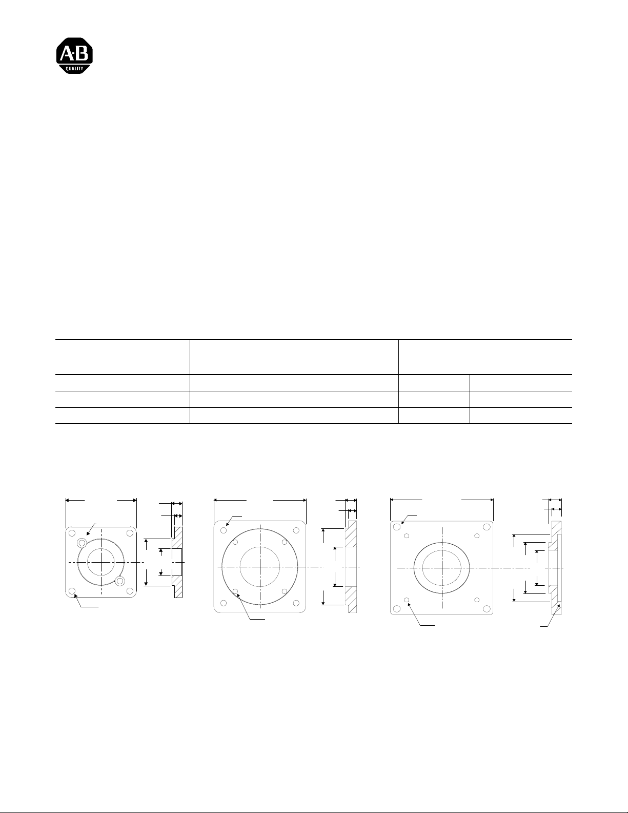
2.27 sq.
0.19 on
1.725 circle
0.205 on 2.625 circle
Note: 0.19 mounting holes (2) are
counterbored 0.31 to 0.18 depth.
0.34
0.25
1.50
0.867
3.48 sq.
0.22 on 3.875 circle
10-32 on 2.625 circle
0.43
0.31
2.875
1.50
Compatible Motors
From N-Series to TL-Series NEMA
TL-TRPLAT-34-42TL-TRPLAT-23-34TL-TRPLAT-17-23
4.0 sq.
0.28 on 4.95 circle
0.28 on 4.95 circle
2.875
2.188
10-32 on 3.875 circle
0.15 deep
0.50
0.375
1.50
Note: The standoff resulting from the transition plate depth reduces the shaft extension on the TL-Series NEMA motor to the nominal shaft extension of an N-Series motor.
Publication TL-IN002A-EN-P — December 2004
Page 2
Installation Instructions
!
To attach an transition plate to a TL-Series NEMA motor:
ATTENTION
1. Align the mounting holes in the transition plate with those in the
TL-Series NEMA motor.
2. Insert the mounting screws from the proper direction, and then torque
each screw to the appropriate value.
• TL-TRPLAT-17-23 requires two screws through the face of the
transition plate and into the front of the motor mount.
• TL-TRPLAT-23-34 and TL-TRPLAT-34-42 require four screws
through the back of the motor mount and into the rear of the
transition plate.
Energy may be stored in a drive system after power is
removed.
Before disconnecting mechanical or electrical connections
to a motor, remove power from the drive system and allow
the bus capacitance to discharge for the time indicated on
the front of the drive.
Failure to observe safety procedures could result in personal
injury or equipment damage.
Catalog Number of Transition Plate Mounting Hardware Torque Requirements
TL-TRPLAT-17-23 Two 8-32 cap screws 3.0 - 3.7 Nm (27 - 33 lb-in.)
TL-TRPLAT-23-34
TL-TRPLAT-34-42
Refer to the TL-Series Servo Motor Installation Instructions (publication
TL-IN001x-EN-P) for detailed information on mounting, maintaining, and
troubleshooting a TL-Series NEMA motor. To obtain a copy, contact your
local Rockwell Automation office or distributor, or access the document
on-line at http://
For more information refer to our web site: www.ab.com/motion
For Allen-Bradley Technical Support information refer to: www.support.rockwellautomation.com or Tel: (1) 440.646.5800
Allen-Bradley, and A-B are registered tradema rks of Rockwell Automation.
www.rockwellautomation.com
Four 10-32 cap screws 6.1 - 7.5 Nm (54 - 66 lb-in.)
/literature.
Publication TL-IN002A-EN-P — December 2004 P/N 9101-0465-001
Copyright © 2004 Rockwell Automation. All rights reserved. Printed in USA.
 Loading...