

Page 1
Installation Instructions
MP-Series and TL-Series Electric Cylinders Replacement Parts
Catalog Numbers MPAR-NA3210C, MPAR-NA323C, MPAR-NA4012C, MPAR-NA405C,
MPAR-NA6310C, MPAR-NA6320C
MPAR-NP3210B, MPAR-NP323B, MPAR-NP4012B, MPAR-NP405B, MPAR-NP6310B,
MPAR-NP6320B
TLY-A1xxx-B-X19x, TLY-A2xxx-B-X19x, TLY-A3xxx-B-Xxxx
MPL-x1520F-V-X20x, MPL-x1530F-V-X20x, MPL-x220F-V-X2xx, MPL-x330F-M-X21x,
MPL-x420F-M-X21x
MPAR-X1xxxB, MPAR-X1xxxE, MPAR-X2xxxC, MPAR-X2xxxF, MPAR-X3xxxE, MPAR-X3xxxH
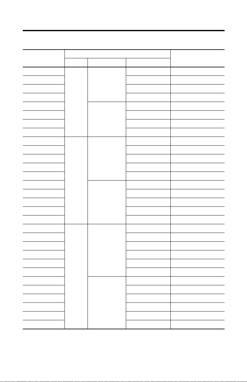
Topi c Pag e
About the MP-Series and TL-Series Electric Cylinder Replacement Parts 1
Important User Information 2
Catalog Number Explanation 3
Before You Begin 6
Replace Inline-mount Electric Cylinder Motor 6
Replace Inline-mount Electric Cylinder Coupling or Actuator Cylinder 7
Replace a Parallel-mount Electric Cylinder Motor or Belt 12
Additional Resources 17
About the MP-Series and TL-Series Electric Cylinder Replacement Parts
Electric cylinders have three replaceable parts; the motor, actuator cylinder, and the transmission
component. For inline-mount electric cylinders, the transmission component is the coupler and
for parallel-mount electric cylinder, it is a belt. Instructions in this manual cover the replacement
of these components.
Page 2
2 MP-Series and TL-Series Electric Cylinders Replacement Parts
Important User Information
Solid-state equipment has operational characteristics differing from those of electromechanical equipment. Safety Guidelines for
the Application, Installation and Maintenance of Solid State Controls (publication SGI-1.1
Automation sales office or online at http://www.rockwellautomation.com/literature/
between solid-state equipment and hard-wired electromechanical devices. Because of this difference, and also because of the wide
variety of uses for solid-state equipment, all persons responsible for applying this equipment must satisfy themselves that each
intended application of this equipment is acceptable.
In no event will Rockwell Automation, Inc. be responsible or liable for indirect or consequential damages resulting from the use or
application of this equipment.
The examples and diagrams in this manual are included solely for illustrative purposes. Because of the many variables and
requirements associated with any particular installation, Rockwell Automation, Inc. cannot assume responsibil ity or liability for
actual use based on the examples and diagrams.
No patent liability is assumed by Rockwell Automation, Inc. with respect to use of information, circuits, equipment, or software
described in this manual.
Reproduction of the contents of this manual, in whole or in part, without written permission of Rockwell Automation, Inc., is
prohibited.
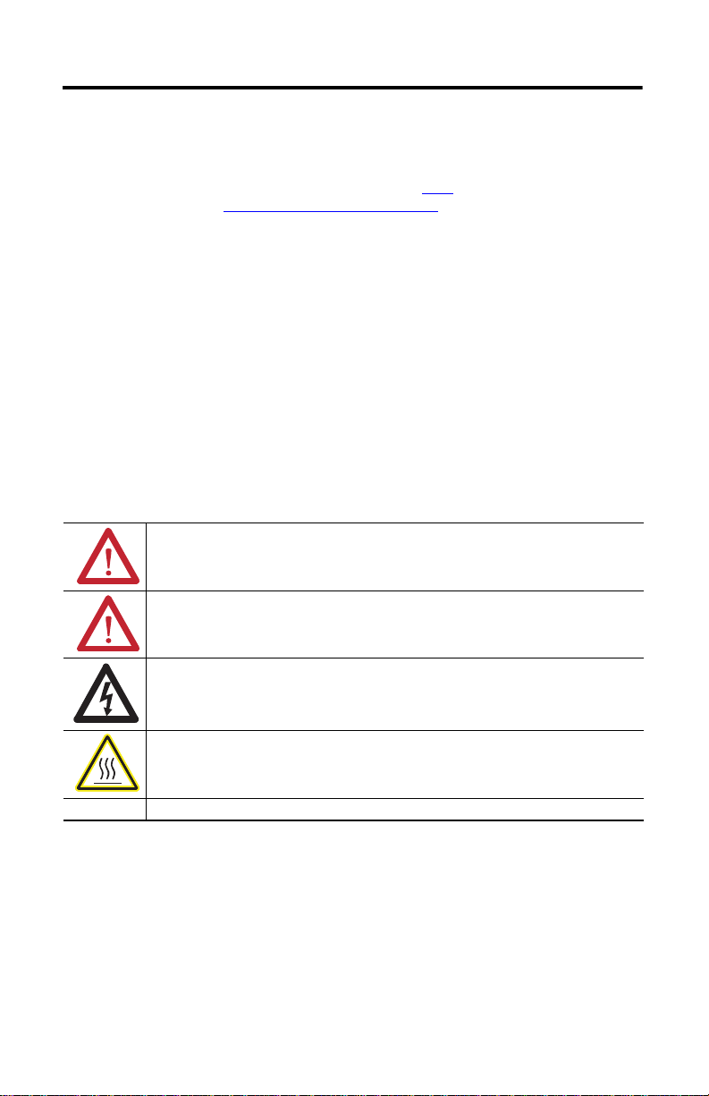
Throughout this manual, when necessary, we use notes to make you aware of safety considerations.
WARNIN G: Identifies information about practices or circumstances that can cause an explosion in a hazardous
environment, which may lead to personal injury or death, property damage, or economic loss.
available from your local Rockwell
) describes some important differences
ATTENTION: Identifies information about practices or circumstances that can lead to personal injury or death,
property damage, or economic loss. Attentions help you identify a hazard, avoid a hazard and recognize the
consequences.
SHOCK HAZARD: Labels may be on or inside the equipment, for example, drive or motor, to alert people that
dangerous voltage may be present.
BURN HAZARD: Labels may be on or inside the equipment, for example, drive or motor, to alert people that
surfaces may reach dangerous temperatures.
IMPORTANT Identifies information that is critical for successful application and understanding of the product.
Rockwell Automation Publication MPAR-IN002B-EN-P - September 2012
Page 3
MP-Series and TL-Series Electric Cylinders Replacement Parts 3
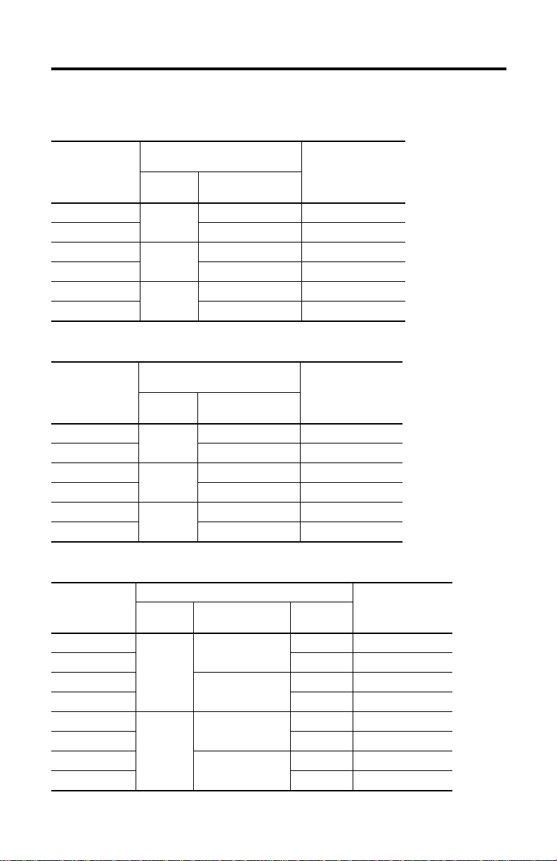
Catalog Number Explanation
Replacement Couplings
Electric Cylinder with Inline
Replacement Coupling
Cat. No.
MPAR-NA3210C
MPAR-NA323C 3.0 (0.118) MPAR-x1xxxB-xxA
MPAR-NA4012C
MPAR-NA405C 5.0 (0.197) MPAR-x2xxxC-xxA
MPAR-NA6310C
MPAR-NA6320C 20.0 (0.787) MPAR-x3xxxH-xxA
Frame Size
32
40
63
Replacement Belts
Replacement Belt
Cat. No.
MPAR-NP3210B
MPAR-NP323B 3.0 (0.118) MPAR-x1xxxB-xxB/D/E
MPAR-NP4012B
MPAR-NP405B 5.0 (0.197) MPAR-x2xxxC-xxB/D/E
MPAR-NP6310B
MPAR-NP6320B 20.0 (0.787) MPAR-x3xxxH-xxB/D/E
Frame Size
32
40
63
Motor Attributes
Ball Screw Pitch
mm/rev (in./rev)
10.0 (0.394) MPAR-x1xxxE-xxA
12.7 (0.500) MPAR-x2xxxF-xxA
10.0 (0.394) MPAR-x3xxxE-xxA
Electric Cylinder with Motor Mounted in
Parallel Attributes
Ball Screw Pitch
mm/rev (in./rev)
10.0 (0.394) MPAR-x1xxxE-xxB/D/E
12.7 (0.500) MPAR-x2xxxF-xxB/D/E
10.0 (0.394) MPAR-x3xxxE-xxB/D/E
Use with Electric Cylinder
Cat. No.
Use with Electric Cylinder
Cat. No.
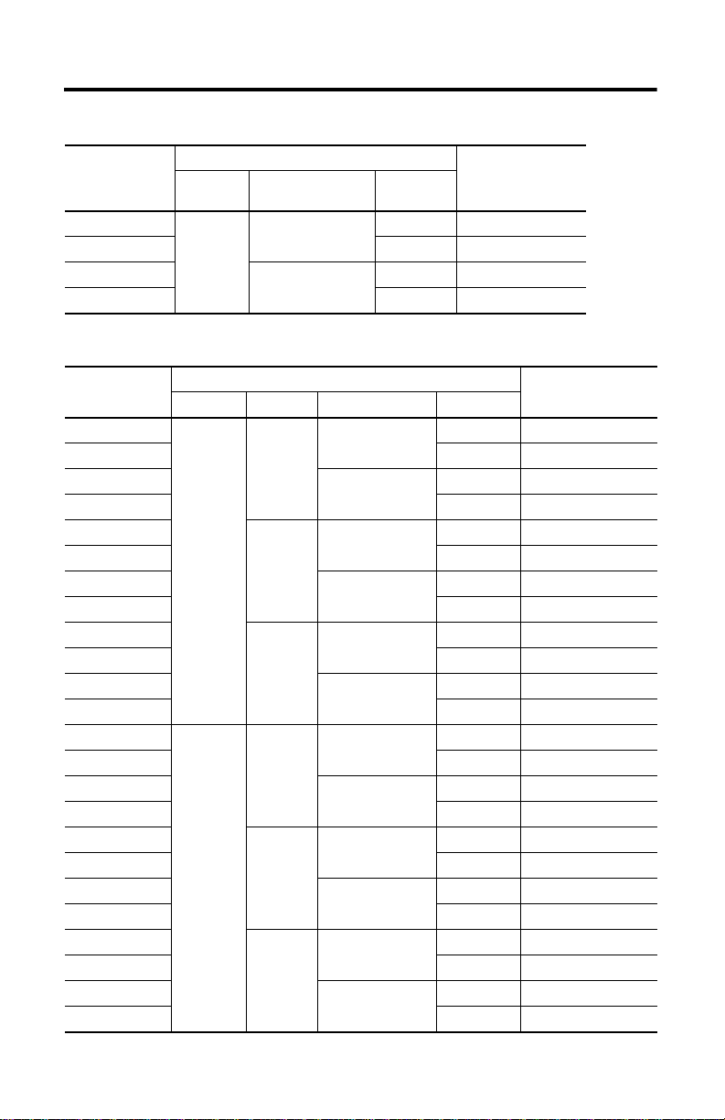
Replacement Motors for TLAR-Series Electric Cylinders
Replacement Moto r
Cat. No.
TLY-A130F-B-X191
TLY-A130F-B-X192 24V Brake TLAR-A1xxxB-x4x
TLY-A220F-B-X193
TLY-A220F-B-X194 24V Brake TLAR-A1xxxE-x4x
TLY-A220F-B-X195
TLY-A220F-B-X196 24V Brake TLAR-A2xxxC-x4x
TLY-A230F-B-X197
TLY-A230F-B-X198 24V Brake TLAR-A2xxxF-x4x
Frame Size
32
40
Electric Cylinder Attributes
Ball Screw Pitch
mm/rev (in./rev)
3.0 (0.118)
10.0 (0.394)
5.0 (0.197)
12.7 (0.5)
Brake
None TLAR-A1xxxB-x2x
None TLAR-A1xxxE-x2x
None TLAR-A2xxxC-x2x
None TLAR-A2xxxF-x2x
Use with Electric Cylinder
Cat. No.
Rockwell Automation Publication MPAR-IN002B-EN-P - September 2012
Page 4
4 MP-Series and TL-Series Electric Cylinders Replacement Parts
Replacement Motors for TLAR-Series Electric Cylinders (continued)
Replacement Motor
Cat. No.
TLY-A310F-B-X199
TLY-A310F-B-X200 24V Brake TLAR-A3xxxE-x4x
TLY-A310F-B-X201
TLY-A310F-B-X202 24V Brake TLAR-A3xxxH-x4x
Frame Size
63
Electric Cylinder Attributes
Ball Screw Pitch
mm/rev (in./rev)
10.0 (0.394)
20.0 (0.787)
Use with Electric Cylinder
Brake
None TLAR-A3xxxE-x2x
None TLAR-A3xxx H-x2x
Cat. No.
Replacement Motor for MPAR-Series Electric Cylinders
Replacement Motor
Cat. No.
MPL-A1520F-V-X203
MPL-A1520F-V-X204 24V Brake MPAR-A1xxxB-x4x
MPL-A1530F-V-X205
MPL-A1530F-V-X206 24V Brake MPAR-A1xxxE-x4x
MPL-A1530F-V-X207
MPL-A1530F-V-X208 24V Brake MPAR-A2xxxC-x4x
MPL-A220F-V-X209
MPL-A220F-V-X210 24V Brake MPAR-A2xxxF-x4x
MPL-A330F-M-X211
MPL-A330F-M-X212 24V Brake MPAR-A3xxxE-x4x
MPL-A420F-M-X213
MPL-A420F-M-X214 24V Brake MPAR-A3xxxH-x4x
MPL-B1520F-V-X215
MPL-B1520F-V-X216 24V Brake MPAR-B1xxxB-x4x
MPL-B1530F-V-X217
MPL-B1530F-V-X218 24V Brake MPAR-B1xxxE-x4x
MPL-B1530F-V-X219
MPL-B1530F-V-X220 24V Brake MPAR-B2xxxC-x4x
MPL-B220F-V-X221
MPL-B220F-V-X222 24V Brake MPAR-B2xxxF-x4x
MPL-B330F-M-X223
MPL-B330F-M-X224 24V Brake MPAR-B3xxxE-x4x
MPL-B420F-M-X225
MPL-B420F-M-X226 24V Brake MPAR-B3xxxH-x4x
Voltag e Class Frame Size Pitch mm/rev (in./rev) Brake
200
400
Electric Cylinder Attributes
32
40
63
32
40
63
3.0 (0.118)
10.0 (0.394)
5.0 (0.197)
12.7 (0.50)
10.0 (0.394)
20 (0.787)
3.0 (0.118)
10.0 (0.394)
5.0 (0.197)
12.7 (0.50)
10.0 (0.394)
20.0 (0.787)
None MPAR-A1xxxB-x2x
None MPAR-A1xxxE-x2x
None MPAR-A2xxxC-x2x
None MPAR-A2xxx F-x2x
None MPAR-A3xxxE-x2x
None MPAR-A3xxx H-x2x
None MPAR-B1xxxB-x2x
None MPARBA1xxxE-x2x
None MPAR-B2xxxC-x2x
None MPAR-B2xxxF-x2x
None MPAR-B3xxxE-x2x
None MPAR-B3xxxH-x2x
Use with Electric Cylinder
Cat. No.
Rockwell Automation Publication MPAR-IN002B-EN-P - September 2012
Page 5
Replacement Actuator
MP-Series and TL-Series Electric Cylinders Replacement Parts 5
Replacement Ac tuator
Cat. No.
MPAR-X1100B
MPAR-X1200B 200 TLAR/MPAR-x1xxxB-xxx
MPAR-X1300B 300 TLAR/MPAR-x1xxxB-xxx
MPAR-X1400B 400 TLAR/MPAR-x1xxxB-xxx
MPAR-X1100E
MPAR-X1200E 200 TLAR/MPAR-x1xxxE-xxx
MPAR-X1300E 300 TLAR/MPAR-x1xxxE-xxx
MPAR-X1400E 400 TLAR/MPAR-x1xxxE-xxx
MPAR-X2100C
MPAR-X2200C 200 TLAR/MPAR-x2xxxC-xxx
MPAR-X2300C 300 TLAR/MPAR-x2xxxC-xxx
MPAR-X2400C 400 TLAR/MPAR-x2xxxC-xxx
MPAR-X2600C 600 TLAR/MPAR-x2xxxC-xxx
MPAR-X2100F
MPAR-X2200F 200 TLAR/MPAR-x2xxxF-xxx
MPAR-X2300F 300 TLAR/MPAR-x2xxxF-xxx
MPAR-X2400F 400 TLAR/MPAR-x2xxxF-xxx
MPAR-X2600F 600 TLAR/MPAR-x2xxxF-xxx
MPAR-X3100E
MPAR-X3200E 200 TLAR/MPAR-x3xxxE-xxx
MPAR-X3300E 300 TLAR/MPAR-x3xxxE-xxx
MPAR-X3400E 400 TLAR/MPAR-x3xxxE-xxx
MPAR-X3600E 600 TLAR/MPAR-x3xxxE-xxx
MPAR-X3800E 800 TLAR/MPAR-x3xxxE-xxx
MPAR-X3100H
MPAR-X3200H 200 TLAR/MPAR-x3xxxH-xxx
MPAR-X3300H 300 TLAR/MPAR-x3xxxH-xxx
MPAR-X3400H 400 TLAR/MPAR-x3xxxH-xxx
MPAR-X3600H 600 TLAR/MPAR-x3xxxH-xxx
MPAR-X3800H 800 TLAR/MPAR-x3xxxH-xxx
Frame Size Pitch mm/rev (in./rev) Stroke Length mm (in.)
32
40
63
Electric Cylinder Attributes
3.0 (0.118)
10.0 (0.394)
5.0 (0.197)
12.7 (0.50)
10.0 (0.344)
20.0 (0.787)
Use with Electric Cylinder
Cat. No.
100 TLAR/MPAR-x1xxxB-xxx
100 TLAR/MPAR-x1xxxE-xxx
100 TLAR/MPAR-x2xxxC-xxx
100 TLAR/MPAR-x2xxxF-xxx
100 TLAR/MPAR-x3xxxE-xxx
100 TLAR/MPAR-x3xxxH-xxx
Rockwell Automation Publication MPAR-IN002B-EN-P - September 2012
Page 6
6 MP-Series and TL-Series Electric Cylinders Replacement Parts
IMPORTANT
Motor
Actuator Cylinder
X
1
Before You Begin
Before you begin, use the Catalog Number Explanation to verify that the replacement parts
match the electric cylinder that you are attempting to repair. Read through the procedure before
beginning repair or replacement.
Replace Inline-mount Electric Cylinder Motor
This procedure applies to Bulletin MPAR-xxxxxx-xxA and TLAR-xxxxxx-xxA electric
cylinders.
Apply Loctite 222 to bolts M4 and Loctite 242 for bolts M5 during assembly steps.
Follow these steps to replace the motor.
1. Disconnect motor and feedback cables.
2. Remove the four bolts that secure the motor to the motor flange.
3. Remove the bolt from the coupling hub on the motor shaft.
4. Remove the coupling hub from the motor shaft.
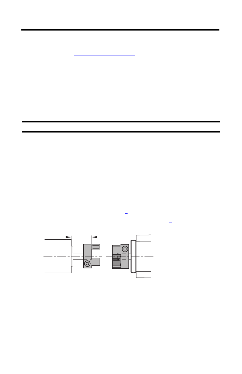
5. Clean the replacement motor shaft with a soft cloth damped with isopropyl alcohol.
6. Position the coupling hub on the replacement motor’s shaft.
Use the dimension from the table on page 7
7. Torque the coupling bolt to the value listed in the table on page 7
.
.
Rockwell Automation Publication MPAR-IN002B-EN-P - September 2012
Page 7

MP-Series and TL-Series Electric Cylinders Replacement Parts 7
IMPORTANT
(1)
X
Cat. No.
MPAR-x1xxxB-xxA
MPAR-x1xxxE-xxATLAR-A1xxxE-BxA 28.8 (1.13)
MPAR-x2xxxF-xxA 22.3 (0.88) TLAR-A2xxxF-BxA
MPAR-x3xxxE-xxA 35.5 (1.40)
MPAR-x3xxxH-xxA 35.2 (1.38) TLAR-A3xxxH-BxA
(1) Tolerance is ± 0.25 mm (0.010 in.).
1
mm (in.)
18.5 (0.73)
Torq ue
N•m (lb•in)
4.0 (35.4)
8.0 (70.8)
Cat. No.
TLAR-A1xxxB-BxA 25.0 (0.98) 0.6 (5.31)
TLAR-A3xxxE-BxA
(1)
X
1
mm (in.)
29.8 (1.17)
30.5 (1.20) 8.0 (70.8)
Torq ue
N•m (lb•in)
4.0 (35.4)MPAR-x2xxxC-xxA 19.5 (0.77) TLAR-A2xxxC-BxA
8. Align the coupling, the motor, and the actuator cylinder, then push them together.
9. Attach the motor to the motor mount flange by using all four bolts.
10. Torque the bolts as follows.
Cat. No. Bolt Size
MPAR-x1xxxx-xxA
MPAR-x2xxxC-xxATLAR-A1xxx
MPAR-x3xxxE-xxA M6 x 25 9.9 (87.6) TLAR-A2xxxF-BxA
MPAR-x3xxxH-xxA M8 x 25 24.0 (212.4) TLAR-A3xxxE-BxA
M5 x 20 5.9 (52.2)
Torq ue
N•m (lb•in)
Cat. No. Bolt Size
TLAR-A1xxxB-BxA M4 x16 2.9 (25.6)
E-BxA
TLAR-A3xxxH-BxA
M5 x16 5.9 (52.2)MPAR-x2xxxF-xxATLAR-A2xxxC-BxA
M6 x 20 9.9 (87.6)
Torq ue
N•m (lb•in)
Replace Inline-mount Electric Cylinder Coupling or Actuator Cylinder
This procedure applies to Bulletin MPAR-xxxxxx-xxA and TLAR-xxxxxx-xxA electric
cylinders.
Follow these steps to replace the coupling or actuator cylinder.
Apply Loctite 222 to bolts M4 and Loctite 242 for bolts M5 during assembly steps.
1. Disconnect the motor and feedback cables.
Rockwell Automation Publication MPAR-IN002B-EN-P - September 2012
Page 8

8 MP-Series and TL-Series Electric Cylinders Replacement Parts
1
2
3
4
2
6
5
Gear Ring
Coupling Hubs
Actuato r Cylinder
Motor
2. Disassemble the motor, motor flange, and coupling housing, using the following
diagram.
Item Description Item Description
1Motor 4Coupling housing
2 Coupling hub 5 Gear ring
3Motor flange 6Actuator cylinder
Replace Only the Coupling
If you are replacing the coupling only, follow these steps. If replacing the actuator cylinder go to
Replace Only the Actuator Cylinder
on page 10.
1. Remove the coupling hubs from the
motor and actuator.
2. Pull apart the new coupling.
3. Insert the new gear ring in one of the
coupling hubs.
4. Position the coupling hub with
matching diameter on the motor.
5. Position the coupling hubs with matching diameter on the actuator cylinder shaft.
Rockwell Automation Publication MPAR-IN002B-EN-P - September 2012
Page 9

MP-Series and TL-Series Electric Cylinders Replacement Parts 9
Use the dimension from the table.
Motor
X
1
Y
1
Actuator Cylinder
6. Tighten the clamping bolts on both the coupling hubs to the specified torque.
Continue with Assemble the Electric Cylinder
on page 10.
(1)
X
Cat. No.
MPAR-x1xxxB
MPAR-x1xxxETLAR-x1xxxE
MPAR-x2xxxF
MPAR-x3xxxE 35.5 (1.4)
MPAR-x3xxxH
(1) Tolerance is ± 0.25 mm (0.010 in.).
1
mm (in.)
18.5
(0.73)
19.5
(0.77)
22.3
(0.88)
35.2
(1.38)
(1)
Y
1
mm (in.)
19.3
(0.76)
18.3
(0.72)
27.0
(1.06)
Torq ue
N•m (lb•in)
4.0 (35.4)
8.0 (70.8)
Cat. No.
TLAR-x1xxxB
TLAR-x2xxxC
TLAR-x2xxxF
TLAR-x3xxxE
TLAR-x3xxxH
(1)
X
1
mm (in.)
25.0
(0.98)
28.8
(1.13)
29.8
(1.17)
30.5
(1.20)
(1)
Y
1
mm (in.)
16.8
(0.66)
19.3
(0.76)
18.3
(0.72)
27.0
(1.06)
Torq ue
N•m (lb•in)
0.6 (5.31)
4.0 (35.4)MPAR-x2xxxC
8.0 (70.8)
Rockwell Automation Publication MPAR-IN002B-EN-P - September 2012
Page 10

10 MP-Series and TL-Series Electric Cylinders Replacement Parts
Coupling Housing
Actuator Cylinder
Coupling Housing
Actuator Cylinder
Motor Flange
Replace Only the Actuator Cylinder
1. Remove the coupling hub from the actuator cylinder.
2. Remove the bolt from the coupling hub.
3. Position the coupling hub on the shaft of the actuator cylinder.
Use the dimension shown on the table in step 6
on page 9.
4. Tighten the coupling hub bolt to the torque shown on the table in step 6
Continue with Assemble the Electric Cylinder
on page 10.
Assemble the Electric Cylinder
1. Attach the coupling housing by using four bolts.
2. Torque the bolts as shown in this table.
on page 9.
Cat. No.
MPAR-x1xxxx-xxA
MPAR-x2xxxC-xxA TLAR-A1xxxE-BxA
MPAR-x2xxxF-xxA TLAR-A2xxxC-BxA
MPAR-x3xxxE-xxA
MPAR-x3xxxH-xxA TLAR-A3xxxE-BxA
Bolt
Size
M6 x 30 4.2 (37.17)
M8 x 40 7.8 (69)
Torq ue
N•m (lb•in)
Cat. No.
TLAR-A1xxxB-BxA
TLAR-A2xxxF-BxA
TLAR-A3xxxH-BxA
3. Attach the motor flange by using the required number of bolts.
See table in following the step for the bolt quantity.
Rockwell Automation Publication MPAR-IN002B-EN-P - September 2012
Bolt
Size
M6 x 20 4.2 (37.17)
M8 x 40 7.8 (69)
Torq ue
N•m (lb•in)
Page 11

MP-Series and TL-Series Electric Cylinders Replacement Parts 11
Align Coupling Hubs
4. Torque the bolts as shown in this table.
Cat. No.
MPAR-x1xxxx-xxA
MPAR-x2xxxC-xxA TLAR-A1xxxE-BxA
MPAR-x2xxxF-xxA TLAR-A2xxxC-BxA
MPAR-x3xxxE-xxA
MPAR-x3xxxH-xxA 3 TLAR-A3xxxE-BxA
Bolt
Quantity
4
Torq ue
Bolt
N•m
Size
(lb•in)
2.9
M4 x 12
(25.6)
M6 x 20 9.9 (87.6)
Cat. No.
TLAR-A1xxxB-BxA
TLAR-A2xxxF-BxA
TLAR-A3xxxH-BxA
Bolt
Quantity
4
Bolt
Size
M3 x 12
M4 x 16
M6 x 16
5. Align the coupling, the motor, and the actuator cylinder and push them together.
Torq ue
N•m
(lb•in)
1.2
(10.6)
2.9
(25.6)
9.9
(87.6)
6. Attach the motor to the motor mount flange by using all four bolts.
7. Tor qu e b o lt s as fo ll ow s.
Cat. No.
MPAR-x1xxxx-xxA
MPAR-x2xxxC-xxATLAR-A1xxxE-BxA
MPAR-x3xxxE-xxA M6 x 25 9.9 (87.6) TLAR-A2xxxF-BxA
MPAR-x3xxxH-xxA M8 x 25 24.0 (212.42) TLAR-A3xxxE-B
Bolt
Size
M5 x 20 5.9 (52.2)
Torq ue
N•m (lb•in)
Cat. No. Bolt Size
TLAR-A1xxxB-BxA M4 x 16 2.9 (25.6)
xA
TLAR-A3xxxH-BxA
M5 x 16 5.9 (52.2)MPAR-x2xxxF-xxATLAR-A2xxxC-BxA
M6 x 20 9.9 (87.6)
Rockwell Automation Publication MPAR-IN002B-EN-P - September 2012
Torq ue
N•m (lb•in)
Page 12

12 MP-Series and TL-Series Electric Cylinders Replacement Parts
IMPORTANT
CAUTION
Hot surface.
Do not touch.
Belt Housing
Replace a Parallel-mount Electric Cylinder Motor or Belt
This procedure is for Bulletin MPAR-xxxxxx-xxB/D/E electric cylinders. These steps can be
used to change the motor or the actuator cylinder orientation.
Follow these steps to replace the belt, motor, or actuator cylinder.
Apply Loctite 222 to bolts M4 and Loctite 242 for bolts M5 during assembly steps.
1. Disconnect the motor and feedback cables.
2. If the motor has brake, release the brake on motor so that the rod moves freely.
3. Position the rod to the center of travel.
4. Remove the cover from belt housing.
ATTENTION: Exposed moving parts can cause severe injury. Do not the operate electric c ylinder
without the cover in place. Follow the lock-out procedures before servicing the machine.
Rockwell Automation Publication MPAR-IN002B-EN-P - September 2012
Page 13

MP-Series and TL-Series Electric Cylinders Replacement Parts 13
Motor Mount Bolts (4X)
Spacer Ring
Belt
Pulleys
5. Loosen, but do not remove the four blots that hold the motor to the belt housing.
This relieves the tension on the belt.
6. Remove the pulleys and the belt.
Use a wrench to hold the pulley in place while turning the collar clockwise with a hex
driver.
The pulley has a left hand thread.
7. If you are changing the motor or actuator cylinder orientation, follow steps 7a through
7e; if not, go to step 8
.
Rockwell Automation Publication MPAR-IN002B-EN-P - September 2012
Page 14

14 MP-Series and TL-Series Electric Cylinders Replacement Parts
IMPORTANT
a. Remove the bolts from the motor or actuator cylinder.
Be sure to collect all the square nuts if you are removing the motor.
b. Reposition the motor and or actuator cylinder.
If you are mounting the motor with the connectors between the actuator cylinder
and the motor, rotate the motor connec tors so they exit 180° away from the shaft.
c. Attach the actuator cylinder with four bolts.
d. Torque the actuator cylinder bolts to values shown in this table.
Cat. No.
MPAR-x1xxxB-xxB/D/E
MPAR-x1xxxE-xxB/D/E
MPAR-x2xxxC-xxB/D/E
MPAR-x2xxxF-xxB/D/E
MPAR-x3xxxE-xxB/D/E
MPAR-x3xxxH-xxB/D/E
Bolt
Size
M6 x 18 4.2 (37.17
M8 x 20 7.8 (69)
Torq ue
N•m (lb•in)
e. Attach the motor by using four bolts and four square nuts.
Do not tighten bolts at this time.
8. Place the spacer rings, belt, and pulleys on the shafts.
Bottom out pulleys to make them parallel.
Rockwell Automation Publication MPAR-IN002B-EN-P - September 2012
Page 15

MP-Series and TL-Series Electric Cylinders Replacement Parts 15
IMPORTANT
X
Y
XY
Fv
Fv
Untensioned: X <Y
Tensioned: X = Y
9. Hold the pulleys with a wrench and tighten the collar by turning the hex key
counter-clockwise to the torque shown in this table.
Cat. No.
MPAR-x1xxxB-xxB/D/E
MPAR-x2xxxC-xxB/D/E
MPAR-x2xxxF-xxB/D/E
MPAR-x3xxxH-xxB/D/E
Torq ue
N•m (lb•ft)
16.95 (13)MPAR-x1xxxE-xxB/D/E
67.79 (50) MPAR-x3xxxE-xxB/D/E
10. Apply pressure to the base of the motor to tension the belt.
Observe the distance a X and Y and determine this transition precisely.
This table shows the recommend belt tension values.
Cat. No.
MPAR-x1xxxB-xxB/D/E 30 (6.75)
MPAR-x1xxxE-xxB/D/E 61 (13.73)
MPAR-x2xxxC-xxB/D/E 67 (15.10)
MPAR-x2xxxF-xxB/D/E 90 (20.23)
MPAR-x3xxxE-xxB/D/E 162 (36.4)
MPAR-x3xxxH-xxB/D/E 224 (50.4)
Recommend Belt Tension
N (lb)
A low pretension force is better than a high pretension force.
Excessive pretension on the belt results in:
• impermissible radial loads causing shaft to break
• increased wear in the axis and motor gearings
• reduction of the service life of the belt
Rockwell Automation Publication MPAR-IN002B-EN-P - September 2012
Page 16

16 MP-Series and TL-Series Electric Cylinders Replacement Parts
11. While a maintaining on tension on the belt, torque the motor bolts to value specified in
this table.
Cat. No. Bolt Size
MPAR-x1xxxB-xxB/D/E
MPAR-x1xxxE-xxB/D/E
MPAR-x2xxxC-xxB/D/E
MPAR-x2xxxF-xxB/D/E M5 x 20
MPAR-x3xxxE-xxB/D/E M6 x 18 9.8 (87.6)
MPAR-x3xxxH-xxB/D/E M8 x 20 24.0 (212.0)
M5 x 16
Torq ue
N•m (lb•in)
5.9 (52.2)
12. Secure the cover to the belt housing with five bolts.
Rockwell Automation Publication MPAR-IN002B-EN-P - September 2012
Page 17

MP-Series and TL-Series Electric Cylinders Replacement Parts 17
Additional Resources
These documents contain additional information concerning related products from Rockwell
Automation.
Resource Description
MP-Series Electric Cylinders Installation Instructions,
publication MPAR-IN001
TL-Series Electric Cylinders Installation Instructions,
publication TLAR-IN001
MP-Series Brushless Servo Motor Installation Instruc tions,
publication MP-IN001
MP-Series Brushless Servo Motor Installation Instruc tions,
publication MP-IN006
Product Certifications website http://www.ab. com Provides declarations of conformity, certificates, and other
You can view or download publications at http://www.rockwellautomation.com/literature. To
order paper copies of technical documentation, contact your local Allen-Bradley distributor or
Rockwell Automation sales representative.
Information on installing MP-Series electric cylinders
Information on installing TL-Series electric cylinders
Information on installing, medium frame (100…165 mm)
MP-Series low-inertia motors
Information on installing small frame (<75 mm) MP-Series
low-inertia motors
certification details
Rockwell Automation Publication MPAR-IN002B-EN-P - September 2012
Page 18

18 MP-Series and TL-Series Electric Cylinders Replacement Parts
Notes:
Rockwell Automation Publication MPAR-IN002B-EN-P - September 2012
Page 19

Notes:
MP-Series and TL-Series Electric Cylinders Replacement Parts 19
Rockwell Automation Publication MPAR-IN002B-EN-P - September 2012
Page 20

Rockwell Automation Support
Rockwell Automation provides tec hnical information on the Web to assist you in using its products.
At http://www.rockwellautomation.com/support
links to software service packs, and a MySupport feature that you can customize to make the best use of these tools. You c an also visit
our Knowledgebase at http://www.rockwellautomation.com/knowledgebase
forums, software updates, and to sign up for product notification updates.
For an additional level of technical phone support for installation, configuration and troubleshooting, we offer TechConnect
support programs. For more information, contact your local distributor or Rockwell Automation representative, or visit
http://www.rockwellautomation.com/support/
Installation Assistance
If you experience a problem within the first 24 hours of installation, please review the information that's contained in this manual.
You can also contact a special Customer Support number for initial help in getting your product up and running.
United States or Canada 1.440.6 46.3434
Outside United States or
Canada
Use the Wor ldwi de Loc ator
http://www.rockwellautomation.com/support/americas/phone_en.html
Rockwell Automation representative.
New Product Satisfaction Return
Rockwell Automation tests all o f its products to ensure that they are fully operational when shipped from the manufacturing facility.
However, if your produc t is not functioning and needs to be returned, follow these procedures.
, you can find technical manuals, technical and application notes, sample code and
for FAQs, technical information, support chat and
SM
.
at
, or contact your local
United States
Outside United States Please contact your local Rockwell Automation representative for the return procedure.
Contact your distributor. You must provide a Customer Support case number (call the phone number
above to obtain one) to your distributor to complete the return process.
Documentation Feedback
Your comments will help us serve your documentation needs better. If you have any suggestions on how to improve this document,
complete this form, publication RA-DU002
Allen-Bradley, MP-Series, Rockwell Software, Rockwell Automation, and TL-Series are trademarks of Rockwell Automation, Inc.
Trademarks not belonging to R ockwell Automation are property of their respective companies.
Rockwell Otomasyon Ticaret A.Ş., Kar Plaza İş Merkezi E Blok Kat:6 34752 İçerenköy, İstanbul, Tel: +90 (216) 5698400
Publication MPAR-IN002B-EN-P - September 2012 814069
Supersedes Publication MPAR-IN002A-EN-P - April 2010 Copyright © 2012 Rockwell Automation, Inc. All rights reserved. Printed in the U.S.A.
, available at http://www.rockwellautomation.com/literature/.
 Loading...