

Page 1

Triguard SC300E
THR
Hot Repair Adaptor
(THR)
Issue 6
INTRODUCTION
PURPOSE
The Hot Repair Adaptor kit enables the backplane field connectors of two adjacent I/O modules
to be bridged so that both are connected to a single set of field connections in a Dual Hot
Re
pair configuration. The kit comprises two Hot Repair Adaptor cards and the appropriate
hardware
shown in Figure 3-1.
This document is intended to provide a general understa
adaptor sufficient to enable basic maintenance operations to be effected in the field.
fittings. The assembly and fitting of one adaptor card to the chassis backplane is
nding of the function of the hot repair
October 2005
ASSOCIATED DOCUMENTATION
008-5097
Reference No
SPECIFICATION
Model
Connectors A and B
Current rating (per contact)
Insulation test voltage
Voltage rating
Overall size (mm)
Overall size (inches)
Weight
Title
Chassis User Manual
34 pin DIN41612. Connector A pins press
fitted.
1.6A max at 60°C
1.5kVdc
132Vac/dc maximum
102H x 51W x 28D
4.0H x 2.0W x 1.1D
0.65kg
THR
008-5106
Page 2

2THR
October
2005–
Issue 6
Triguard
SC300E
ENVIRONMENTAL SPECIFICATIONS
The maximum ambient temperature measured at the hottest point within the Triguard system
shall
not be greater than 60 degrees centigrade.
Temperature operating:
Temperature
Humidity
EMC/RFI
Vibration/Shock
Certification:
General Certification: Ref. SC300E Product Guide (ref 008-5209)
storage:
Immunity
+5°C to +60°C
-
25°C to +70°C
5% to 95
Tested and certified to IEC 1131-Part 2 1994
Tested and certified to IEC 1131-Part 2 1994
% non-condensing at ambient <40°C
TRANSPORT AND HANDLING
The hot repair adaptor must be transported and stored in its original packing material which
should be retained for this purpose.
Page 3
THROctober
2005–
Issue 6
3
Triguard
SC300E THR Hot Repair Adaptor
TECHNICAL DESCRIPTIO
N
PHYSICAL
The Hot Repair Adaptor kit comprises two adaptor cards and hardware fittings
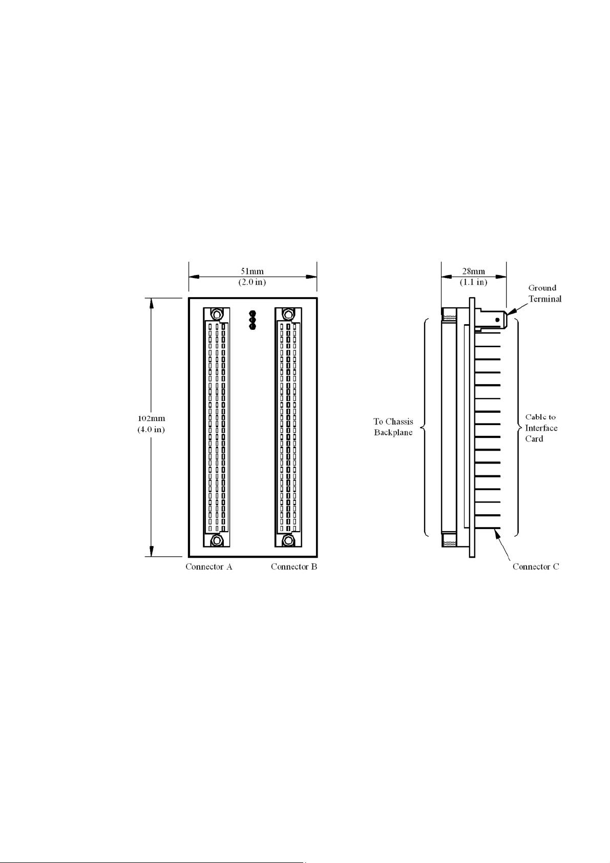
The tracks in each adaptor card connect corresponding pins of the two sockets that mate with
the backplane connectors. The rear of Connector ‘A’ is unused, the pins are cut short and
protected by the shell and cover (items 7 and 6 respectively). The pins of the left hand socket
protrude through a shroud which enables the connection of the field DIN connector.
Figure 2-1. THR Front and side views
Page 4

4THR
October
2005–
Issue 6
Triguard
SC300E
SERVICING
SCOPE
No servicing is necessary, repair is by replacement of the faulty adaptor.
ASSEMBLY AND FITTING
The Hot Repair Adaptor kit comprises two adaptor cards and hardware fittings.
Item No
(refer to Figure 3-1)
1 099-1245
2 600-1079
3 525-7625
4 507-0175
5 525-7619
Table 3-1. Contents of Hot Repair Adaptor kit
Part No.
Description
Hot repair adaptor card
M3 x 3mm spacer
M2.5 x 25mm screw
M2.5 x spring washer
M2.5 x 19mm screw
No. off
2
4
4
8
4
6 442-1016
7 442-1015
Incorrect fitting of an adaptor may result in irreparable damage to the chassis backplane
Prior to the connection of any system cables, fit the Hot Repair Adaptors in the following
manner.
Refer to Figure 3-1.
1.
2.
3.
4.
Check the contents of the Hot Repair Adaptor kit against the list in Table 3-1.
Identify the two adjacent slots to be configured for hot repair.
Remove the four black shrouds from the slot field outlets. Retain two of the shrouds.
Check that none of the backplane connector pins are bent or misaligned.
Cover
Shell
CAUTION
2
2
5.
Carefully position one of the adaptor cards the right way up over two of the backplan
connectors by aligning the top screw holes and gently entering the two top pins into
each connector.
e
Page 5

THROctober
2005–
Issue 6
5
6.
7.
8.
9.
Triguard
Attempt to fully engage the adaptor card but if excessive resistance is felt remove the
card and check for bent pins or any other obstructions.
U
sing items 2, 3 and 4 fit one of the shrouds to the card over the pins of the left hand
connector;
Note that the two spacers (item 2) fit between the shroud and the card. Do not over
tighten the screws.
Using items 4 and 5 fit the shell (item 7) to the card over the short pins of the right
hand connector. Do not over tighten the screws.
Insert the cover (item 6) into the shell (item 7).
ensure that the shroud is correctly oriented (keys on the left, Figure 3-1. ).
SC300E THR Hot Repair Adaptor
10.
Repeat steps e) to i) to fit the other adaptor card to the remaining two field connectors.
Page 6

6THR
October
2005–
Issue 6
Triguard
SC300E
Figure 3-1. THR Exploded view
Page 7

THROctober
2005–
Issue 6
7
Triguard
SC300E THR Hot Repair Adaptor
SERVICE SUPPORT
SPARE PARTS
Spare parts and technical advice can be obtained from your local area offices
.
 Loading...