

Page 1

Triguard SC300E
TDO16AIN
16-Channel Digital Output
Termination Card Introduced Power
24Vdc
(TDO16AIN)
Issue 6
INTRODUCTION
PURPOSE
The TDO16AIN 16-channel digital output termination card acts as an interface between the
digital output circuits of an SC300E chassis and the field devices which they control.
October 2005
It provides:
• Screw terminals for the field wiring
• Power supply inputs for the field devices
• Fuse protection for the field loops with local and remote indication of fuse failure
•
• Dummy loads for unused digital output channels—to prevent spurious operation of
This document is intended to provide a general understanding of the function of the TDO16AIN,
sufficient
Ove rvol ta ge prot ec ti on
latent fault detection circuits in the associated digital output module. (Dummy loads
are only to be connected to outputs which are not used).
to
enable basic maintenance operations to be effected in the field.
ASSOCIATED DOCUMENTATION
Reference
008-5102
MDO32BNS 32-Channel Digital Output Module User Manual
Title
008-5104
008-5150
PDD2
MDO64BNS 64-Channel Digital Output Module User Manual
4 Power Distribution Panel User Manual
008-5135
Page 2

2
TDO16AIN
October
2005–
Issue 6
Triguard
SC300E
SPECIFICATION
Model
TDO16AIN
Power supply inputs
No. of digital input channels
Nominal field supply voltage
Maximum field supply voltage
Maximum field supply curren
Fuse in each positive line to field
Chassis cable connector
Field cable connector
Fuse blown indication
Safety ground terminal TS1
Instrument 0V terminal TS2
Overall size (mm)
Overall
Weight
size (inches)
t
34 way DIN41612
Has four separate connectors (FS1, FS2, FS3
and
FS4) for dc power supplies. The four
positive
the digital outputs via common buses. The
buses
applications
can
loaded
power
16
24Vdc
33Vdc
9A for each of the four input connectors (do
not
1A, fast acting, indicating
Screw terminal to suit 2.5mm2wire (16 AWG)
Local: Fuse blown LED (one per card)
Remote: Fuse blown alarm output (PL1) –
be
Distribution
M3 threaded bush provision for a ring terminal.
Allows
grounded
channels
d
M3 threaded bush provision for a ring terminal.
Allows
transient
162L x 125W x 107H
6.4L x 4.9W x 4.
0.37kg
supplies feed individual sections of
are linked together. For lightly loaded
(e.g. 6A) all the required power
be
supplied via one connector. For highly
applications (e.g. 16A) use multiple
connectors.
exceed 16A total)
connected to Fuse blown LED on Power
Panel (PDD24).
the common 0V supply bus to be
via a 10k ohm resistor. Prevents the
from floating if the card is
isconnected from the chassis.
the field 0V to be commoned for
suppression protection.
2H
can
Page 3

TDO16AIN
October
2005–
Issue 6
3
Triguard
SC300E TDO16AIN 16-Channel D/O Termination Card 24Vdc
ENVIRONMENTAL SPECIF
The maximum ambient temperature measured at the hottest point within the Triguard system
shall
not be greater than 60 degrees centigrade.
Temperature operating:
Temperature
Humidity:
EMC/RFI
Vibration/Shock:
Certification:
General Certification: Ref. SC300E TMR Product G
storage:
Immunity:
ICATIONS
+5°C to +60°C
-
25°C to +70°C
5% to 95% non-condensing at ambient < 40°C
Tested and certified to IEC 1131-Part 2 1994
Tested and certified to IEC 1131-Part 2 1994
uide (ref 008-5209).
TRANSPORT AND HANDLING
The termination card must be transported and stored in its original packing material which
should be retained for this purpose.
Page 4
4
TDO16AIN
October
2005–
Issue 6
Triguard
SC300E
TECHNICAL DESCRIPTIO
N
PHYSICAL
The TDO16AIN comprises a PCB assembly mounted in a moulded carrier that can be snapped
onto all commercially available styles of DIN EN mounting rail. Connection to the chassis
backplane is via a multicore cable terminated at either end by a DIN41612 connector. Figure 2
2 shows the TDO16AIN with the DIN4
type NS 35/5.
1612 connector attached and mounted on rail EN 50022
-
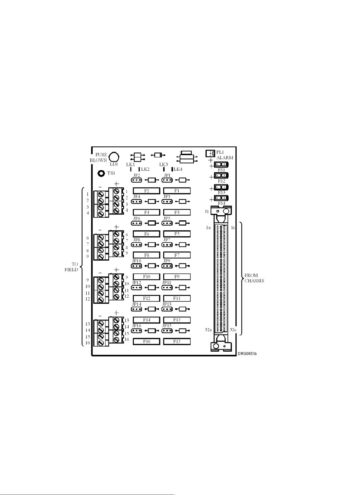
Figure 2-1 General view and component layout
Page 5

TDO16AIN
October
2005–
Issue 6
5
Triguard
SC300E TDO16AIN 16-Channel D/O Termination Card 24Vdc
Figure 2-2 Leading dimensions and mounting schematic
Page 6

6
TDO16AIN
October
2005–
Issue 6
Triguard
SC300E
Figure 2-3 Power distribution system
EXTERNAL CONNECTIONS
Fixed terminal
Field terminals 1 to 16 (+)
Chassis connector J1
Field power supply inputs FS1 to FS4
Alarm output PL1
Ground terminal TS1
Header,
Table 2-1.
Details
Screw terminal to suit 2.5mm2wire
Connector, 34-way, DIN41612, female
Header, 2-way, Molex Minifit Jr
Provision for M3 ring terminal
2-way, Molex KK
Page 7

TDO16AIN
October
2005–
Issue 6
7
Triguard
SC300E TDO16AIN 16-Channel D/O Termination Card 24Vdc
THEORY OF OPERATION
Figure 2-4 shows a circuit diagram of a typical digital output channel.
Power supplies for the termination cards are normally provided by a Power Distribution Panel
PDD24.
Power for th
to LK4 are normally present, and in low load applications, external power can be connected to
any
require
Each digital output channel is powered from a common +ve bus. An indicating fuse is fitted in
the digital output signal line to the field device. The ‘fuse failed’ output from each fuse is
connected to a common alarm bus. If any fuse fails, local indication is provided by the
illumination
Alarm output PL1.
The -ve
when the chassis cable is disconnected.
e digital output channels is distributed as shown in Figure 2-3 . Soldered links LK1
one of the four inputs FS1 to FS4. For high load applications, or where the
different supply voltages, cut the links and supply FS1 to FS4 individually.
of
the Fuse blown LED LD1. A signal to operate a remote alarm is available at
bus may be gr
ounded via TS1 if required, preventing the power supplies from ‘floating’
channel groups
Page 8

8
TDO16AIN
October
2005–
Issue 6
Triguard
SC300E
Figure 2-4 Circuit diagram showing a single channel
NOTE
Current for alarm indication is taken from the chassis module digital output signal. An alarm
will be signalled only when the fuse has failed and this output is high.
Power distribution panel PDD24 has a Fuse blown alarm indicator with provision for multiple
inputs.
This facility can be wired to provide fuse blown indication for an entire cabinet.
Page 9

TDO16AIN
October
2005–
Issue 6
9
Triguard
SC300E TDO16AIN 16-Channel D/O Termination Card 24Vdc
SUPPLEMENTARY INFORM
ATION
Dummy loads
Dummy loads are only to be connected to outputs that are not used. Do not connect a
dummy
load in parallel with a real output.
Digital output channel connections
Table 2-2
J1 and the screw terminals.
Pin J1-1a is connected to the -ve
J1 pins, other than J1-1a and those listed in Table 2-2, are not connected.
Channel
lists the digital output channel wiring connections and associated fuses for connector
bus (Figure 2-4).
Screw Terminal
Digital
output
signal to
field
device
Field loop
return
from
device
field
DIN41612 Connector J1
Field loop
fused
ac/dc
supply
chassis
Digital
output
signal from
to
chassis
Link
position
for
dummy
load
Fuse
1
2
3
4
5
6
7
8
9
10
11
12
13
14
14(+)
15
15(+)
16
16(+)
1(+)
2(+)
3(+)
4(+)
5(+)
6(+)
7(+)
8(+)
9(L)
10(L)
11(L)
12(L)
13(L)
1(
-)
2(
-)
3(
-)
4(
-)
5(
-)
6(
-)
7(
-)
8(
-)
9(
10(
11(
12(
13(
14(
15(
16(
-)
-)
-)
-)
-)
-)
-)
-)
J1-2a
J1-4a
J1-6a
J1-8a
J1-10a
J1-12a
J1-14a
J1-16a
J1-18a
J1-20a
J1-22a
J1-24a
J1-26a
J1-28a
J1-30a
J1-32a
J1-2c
J1-4c
J1-6c
J1-8c
J1-10c
J1-12c
J1-14c
J1-16c
J1-18c
J1-20c
F10 JP10
J1-22c
F11 JP11
J1-24c
F12 JP12
J1-26c
F13 JP13
J1-28c
F14 JP14
J1-30c
F15 JP15
J1-32c
F16 JP16
F1
F2
F3
F4
F5
F6
F7
F8
F9
JP1
JP2
JP3
JP4
JP5
JP6
JP7
JP8-IN
JP9
-IN
-IN
-IN
-IN
-IN
-IN
-IN
-IN
-IN
-IN
-IN
-IN
-IN
-IN
-IN
Page 10

10
TDO16AIN
October
2005–
Issue 6
Triguard
SC300E
SERVICING
SCOPE
The TDO16AIN contains all-passive circuitry that is extremely robust. Servicing operations will
therefore
Before replacing a blown fuse, ascertain the cause of failure, and take the appropriate remedial
action.
not normally extend beyond the replacement of blown fuses.
CAUTION
CONFIGURATION
Links LK1 to LK4 are connected by default (see Figure 2-3 ). If all the links are cut, power
supply
connectors FS1 to FS4
will feed individual digital output channel groups as follows:
Table 3-1. Power supply connectors
Link no.
FS1
FS2
FS3
FS4
Channels
Channels 1 to 4
Channels 5 to 8
Channels 9 to 12
Channels 13 to 16
Page 11

TDO16AIN
October
2005–
Issue 6
11
Triguard
SC300E TDO16AIN 16-Channel D/O Termination Card 24Vdc
SERVICE SUPPORT
SPARE PARTS
Spare parts and t
LIST OF SPARES
echnical advice can be obtained f
Circuit Ref
F1 to F16
Part No
380-0013
rom your local area offices.
1A Indicating fuse
Details
 Loading...