

Page 1

Triguard SC300E
TDI16AIA
INTRODUCTION
PURPOSE
16-Channel Digital Input
Termination Card 24Vdc
(TDI16AIA
Issue 3
October 2005
)
The TDI16AIA 16-channel digital input termination card acts as an interface between the digital
signalling
It provides:
• Screw terminal connectors for the field wiring
• Power supply inputs for the field devices
• Fuse protection for the field loops with local and remote indication of fuse failure
• O
This document is intended to provide a general understanding of the function of the TAI16AIA,
sufficient
ASSOCIATED DOCUMENTATION
Reference
008-5101
devices in the field device and the digital in
vervoltage and transient protection
to
enable basic maintenance operations to be effected in the field.
put circuits of an SC300E chassis.
Title
MDI32BIS 32-Channel Digital Input Module User Manual
008-5104
PDD24 Power Distribution Panel User Manual
008-5121
Page 2

2
TAI16AI
A
October
2005–
Issue 3
Triguard
place
be
be
SC300E
SPECIFICATION
Model
TDI16AIA
Power Supply inputs
No. of digital input channels
Nominal field supply voltage
Maximum field supply voltag
Current rating
Fuse in each positive line to field
Chassis cable connector
Field cable connector
Fuse blown indication
e
34 way DIN41612
Has two separate connectors (FS1and FS2)
for redundant dc power supplies. The positive
supplies
diodes. When auctioneering takes
outside the card, the required power may
supplied via a single connector.
16
24Vdc
33Vdc
50mA per channel.
NOTE
Digital
resistance, the current in each channel will be
2.4mA with 24V field supply.
1A, fast acti
Screw terminals to suit 2.5mm2wire (16AWG)
Local: Fuse blown LED (one per card)
Remote: Fuse blown alarm output (PL1) –
be connected to Fuse blown LED on Power
Distribution Panel (PDD24).
feed a common bus via auctioneering
: In normal operation when used with a
Input Module having a 10k ohm input
ng, indicating
can
Transient suppression
Safety ground terminal TS1
Overall size (mm)
Overall size (inches)
Weight
A transient suppressor device between each
field
return line and a common 0V bus clamps
the
field return line voltage (with respect to 0V
common)
+37Vdc to +43Vdc @ 1mA (maximum for
continuous
+70Vdc @ 69A maximum peak pulse current
for 8ms to 20ms
M3 threaded bush provision for a ring terminal.
Allows the common 0V supply bus to
grounded via a 10k ohm resistor. Prevents the
channels from floating if the card is
disconnected from the chassis
162L x 125W x 107H
6.4L x 4.9W x 4.2H
0.35kg
as
follows:
overload)
Page 3

TDI16AI
A
October
2005–
Issue 3
3
Triguard
SC300E
TDI16AIA
16-Channel D/I Termination Card 24Vdc
ENVIRONMENTAL SPECIF
The maximum ambient temperature measured at the hottest point within the Triguar
shall not be greater than 60 degrees centigrade.
Temperature operating:
Temperature
Humidity:
EMC/RFI
Vi
bration/Shock:
Certification:
General Certification: Ref. SC300E TMR Product Guide (ref 008-5209).
storage:
Immunity:
ICATIONS
+5°C to +60°C
-
25°C to +70°C
5% to 95% non-condensing at ambient < 40°C
Tested and certified to IEC 1131-Part 2 1994
Tested and certified to IEC 1131-Part 2 1994
TRANSPORT AND HANDLING
The termination card must be transported and stored in its original packing material wh
should
be
retained for this purpose.
d system
ich
Page 4
4
TAI16AI
A
October
2005–
Issue 3
Triguard
SC300E
TECHNICAL DESCRIPTIO
N
PHYSICAL
The TDI16AIA comprises a PCB assembly mounted in a moulded carrier that can be snapped
onto all commercially available styles of DIN mounting rail. Connection to the chassis
backplane is via a multicore cable terminated at either end by a DIN41612 connector. Figure 2
2 shows the TDI16AIA with the DIN41612 connector attached and mounted on rail EN 50022
type NS 35/5.
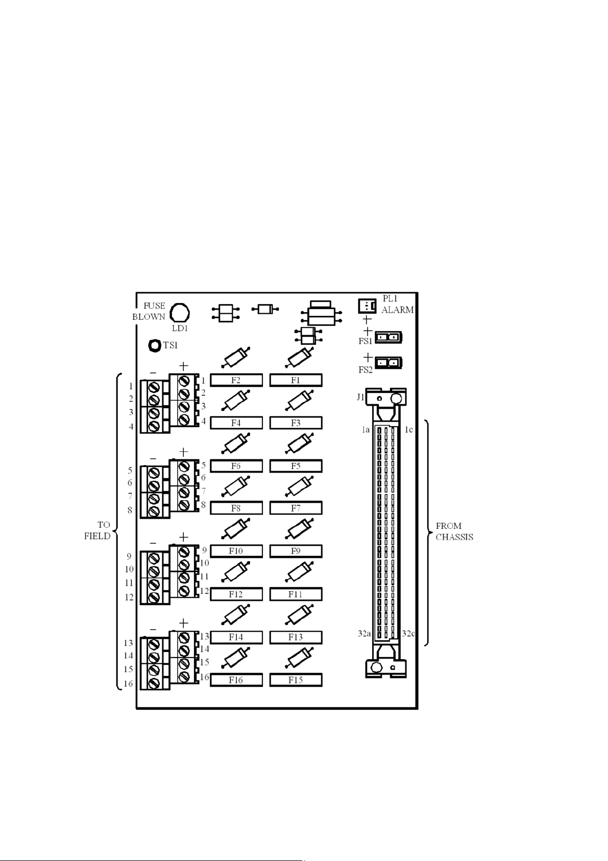
Figure 2-1 identifies the main components on the PCB.
-
Figure 2-
1 General view and component layout
Page 5

TDI16AI
A
October
2005–
Issue 3
5
Triguard
SC300E
TDI16AIA
16-Channel D/I Termination Card 24Vdc
Figure 2-2 Leading dimensions and mounting schematic
Page 6

6
TAI16AI
A
October
2005–
Issue 3
Triguard
SC300E
Figure 2-3 Circuit diagram showing a single channel
Page 7

TDI16AI
A
October
2005–
Issue 3
7
Triguard
SC300E
TDI16AIA
16-Channel D/I Termination Card 24Vdc
EXTERNAL CONNECTIONS
Fixed Terminal
Field terminals 1 to 16 (+) and 1 to 16 (
Chassis connector J1
Field power supply inputs FS1 and FS2
Alarm output PL1
Ground terminal TS1
-)
Screw termin
Connector, 34-way,DIN41612,female
Header, 2-way, Molex Minifit Jr
Header, 2-way, Molex KK
Provision for M3 ring terminal
Details
als to suit 2.5mm2wire
THEORY OF OPERATION
Figure 2-3 is a circuit diagram showing a typical digital input channel.
Power supplies for the termination cards are normally provide
PDD24 which performs diode auctioneering of its dual redundant power supplies
Power for the digital input circuits (normally from the PDD24) is fed to input FS1 or FS2. Where
the
PDD24 is not used and dual supplies are required, these are connected to FS1 and FS2
respectively
and auctioneered on the termination card by D17 and D18.
d by a Power Distribution Panel
.
Each digital input channel is powered via an indicating fuse from a common +ve bus. The ‘fuse
failed’ output from each fuse is connected to a common alarm bus. If any fuse fails, local
indication is provided by the illumination of Fuse blown LED LD1. A signal to operate a remote
alarm
is
available at Alarm output PL1.
The PDD24 has a Fuse blown alarm indicator with provision for multiple inputs. This facility can
be
wired to provide fuse blown indication for an entire cabinet.
The -ve
when the chassis cable is disconnected.
bus may be grounded via TS1 if required, preventing the power supplies from ‘floating’
NOTE
Page 8

8
TAI16AI
A
October
2005–
Issue 3
Triguard
SC300E
TRANSIENT SUPPRESSIO
A transient suppressor is fitted across each digital input channel input to the SC300E chassis.
It provides a discharge path for transient energy pulses that may appear on the digital input line
following
The suppressor is effectively a zener diode with a breakdown voltage just above that of the
normal supply voltage. In normal operation, therefore,
from leakage current). In the presence of a transient pulse, zener breakdown occurs. The
voltage developed across the suppressor varies to some extent with the pulse current and is
known
The following characteristics are typical:
+37V to +43V
+70V
lightning strikes etc.
as
the ‘clamping’ voltage.
Clamping
Voltage
Table 2-1. Transient suppressor characteristics
Pulse
currents
*1mA
**6gAmps
N
the suppressor does not conduct (apart
Pulse
duration
Continuous
8to
20 s
*Maximum current continuous overload
**Maximum
Comments
peak pulse current
SUPPLEMENTARY INFORM
Table 2-2 lists the digital input channel wiring connections and associated fuses for connectors
J1 and J2.
Pin J1-1a is connected to the +ve bus (Figure 2-3 ). Pins J1-1c and J2-1c are interconnected.
J1/J2
pins other than J1-1a, J1-1c, J2-1c and those listed in Table 2-2 are not connected.
ATION
Page 9

Triguard
SC300E
TDI16AIA
16-Channel D/I Termination Card 24Vdc
Channel
1
2
3
4
5
6
7
8
g
10
10(+)
Table 2-2. Digital input channel connections
Screw terminals
Field loop input
signal
1(+)
2(+)
3(+)
4(+)
5(+)
6(+)
7(+)
8(+)
g(+)
Field loop return
field device
from
1(
-)
2(
-)
3(
-)
4(
-)
5(
-)
6(
-)
7(
-)
8(
-)
g(
-)
10(
-)
DIN41612 Connector J1
Field loop
fused (+ve)
input to
chassis
J1-2a
J1-4a
J1-6a
J1-8a
J1-10a
J1-12a
J1-14a
J1-16a
J1-18a
J1-20a
Field loop
fused input
return (-ve)
J1-2c
J1-4c
J1-6c
J1-8c
J1-10c
J1-12c
J1-14c
J1-16c
J1-18c
J1-20c
Fuse
F1
F2
F3
F4
F5
F6
F7
F8
Fg
F10
11
11(+)
12
12(+)
13
13(+)
14
14(+)
15
15(+)
16
16(+)
11(
12(
13(
14(
15(
16(
-)
-)
-)
-)
-)
-)
J1-22a
J1-24a
J1-26a
J1-28a
J1-30a
J1-32a
J1-22c
J1-24c
J1-26c
J1-28c
J1-30c
J1-32c
F11
F12
F13
F14
F15
F16
TDI16AIA
October 2005 – Issue 3 g
Page 10

Triguard
SC300E
SERVICING
SCOPE
The TDI16AIA contains all-passive circuitry that is extremely robust. Servicing operations will
therefore
Before replacing a failed fuse, ascertain the cause of failure, and take the appropriate remedial
action.
not normally extend beyond the replacement of failed fuses.
CAUTION
CONFIGURATION
No configurable links.
10
TAI16AIA
October 2005 – Issue 3
Page 11

Triguard
SC300E
TDI16AIA
16-Channel D/I Termination Card 24Vdc
SERVICE SUPPORT
SPARE PARTS
Spare parts and technical advice can be obtained from your local area
LIST OF SPARES
Circuit Ref
F1 to F16
Part No
380-0013
Details
1A Indicating fuse
offices.
TAI16AIA
October 2005 – Issue 3
 Loading...